EP3784079B1 - Vapour generating system - Google Patents
Vapour generating system Download PDFInfo
- Publication number
- EP3784079B1 EP3784079B1 EP19725282.8A EP19725282A EP3784079B1 EP 3784079 B1 EP3784079 B1 EP 3784079B1 EP 19725282 A EP19725282 A EP 19725282A EP 3784079 B1 EP3784079 B1 EP 3784079B1
- Authority
- EP
- European Patent Office
- Prior art keywords
- vapour generating
- vapour
- cooling chamber
- induction coil
- generating system
- Prior art date
- Legal status (The legal status is an assumption and is not a legal conclusion. Google has not performed a legal analysis and makes no representation as to the accuracy of the status listed.)
- Active
Links
- 238000001816 cooling Methods 0.000 claims description 70
- 230000006698 induction Effects 0.000 claims description 66
- 239000000463 material Substances 0.000 claims description 65
- 239000007788 liquid Substances 0.000 claims description 37
- 238000010438 heat treatment Methods 0.000 claims description 20
- 239000004020 conductor Substances 0.000 claims description 10
- 230000005672 electromagnetic field Effects 0.000 claims description 8
- 229910052751 metal Inorganic materials 0.000 claims description 8
- 239000002184 metal Substances 0.000 claims description 8
- 238000009835 boiling Methods 0.000 claims description 6
- 230000005293 ferrimagnetic effect Effects 0.000 claims description 6
- 230000001419 dependent effect Effects 0.000 claims 3
- 239000003570 air Substances 0.000 description 74
- RYGMFSIKBFXOCR-UHFFFAOYSA-N Copper Chemical compound [Cu] RYGMFSIKBFXOCR-UHFFFAOYSA-N 0.000 description 5
- 229910052802 copper Inorganic materials 0.000 description 5
- 239000010949 copper Substances 0.000 description 5
- LFQSCWFLJHTTHZ-UHFFFAOYSA-N Ethanol Chemical compound CCO LFQSCWFLJHTTHZ-UHFFFAOYSA-N 0.000 description 4
- 238000013459 approach Methods 0.000 description 4
- 230000005291 magnetic effect Effects 0.000 description 4
- 239000012528 membrane Substances 0.000 description 4
- 241000208125 Nicotiana Species 0.000 description 3
- 235000002637 Nicotiana tabacum Nutrition 0.000 description 3
- DNIAPMSPPWPWGF-UHFFFAOYSA-N Propylene glycol Chemical compound CC(O)CO DNIAPMSPPWPWGF-UHFFFAOYSA-N 0.000 description 3
- 239000000443 aerosol Substances 0.000 description 3
- PEDCQBHIVMGVHV-UHFFFAOYSA-N Glycerine Chemical compound OCC(O)CO PEDCQBHIVMGVHV-UHFFFAOYSA-N 0.000 description 2
- XEEYBQQBJWHFJM-UHFFFAOYSA-N Iron Chemical compound [Fe] XEEYBQQBJWHFJM-UHFFFAOYSA-N 0.000 description 2
- PXHVJJICTQNCMI-UHFFFAOYSA-N Nickel Chemical compound [Ni] PXHVJJICTQNCMI-UHFFFAOYSA-N 0.000 description 2
- 229910001053 Nickel-zinc ferrite Inorganic materials 0.000 description 2
- 229910052782 aluminium Inorganic materials 0.000 description 2
- 239000004411 aluminium Substances 0.000 description 2
- XAGFODPZIPBFFR-UHFFFAOYSA-N aluminium Chemical compound [Al] XAGFODPZIPBFFR-UHFFFAOYSA-N 0.000 description 2
- 239000012080 ambient air Substances 0.000 description 2
- 235000019441 ethanol Nutrition 0.000 description 2
- 229960004756 ethanol Drugs 0.000 description 2
- 229910000595 mu-metal Inorganic materials 0.000 description 2
- 239000002245 particle Substances 0.000 description 2
- 230000005855 radiation Effects 0.000 description 2
- 239000007787 solid Substances 0.000 description 2
- 239000000126 substance Substances 0.000 description 2
- 238000009834 vaporization Methods 0.000 description 2
- XLYOFNOQVPJJNP-UHFFFAOYSA-N water Substances O XLYOFNOQVPJJNP-UHFFFAOYSA-N 0.000 description 2
- 229910000859 α-Fe Inorganic materials 0.000 description 2
- 229920003043 Cellulose fiber Polymers 0.000 description 1
- 229920000742 Cotton Polymers 0.000 description 1
- 241000196324 Embryophyta Species 0.000 description 1
- 229910018487 Ni—Cr Inorganic materials 0.000 description 1
- 238000010521 absorption reaction Methods 0.000 description 1
- 229910045601 alloy Inorganic materials 0.000 description 1
- 239000000956 alloy Substances 0.000 description 1
- 230000015556 catabolic process Effects 0.000 description 1
- 238000006243 chemical reaction Methods 0.000 description 1
- VNNRSPGTAMTISX-UHFFFAOYSA-N chromium nickel Chemical compound [Cr].[Ni] VNNRSPGTAMTISX-UHFFFAOYSA-N 0.000 description 1
- YOCUPQPZWBBYIX-UHFFFAOYSA-N copper nickel Chemical compound [Ni].[Cu] YOCUPQPZWBBYIX-UHFFFAOYSA-N 0.000 description 1
- 238000006731 degradation reaction Methods 0.000 description 1
- 230000000694 effects Effects 0.000 description 1
- 239000000945 filler Substances 0.000 description 1
- 230000004907 flux Effects 0.000 description 1
- 239000006261 foam material Substances 0.000 description 1
- 235000011187 glycerol Nutrition 0.000 description 1
- 239000008187 granular material Substances 0.000 description 1
- 238000003780 insertion Methods 0.000 description 1
- 230000037431 insertion Effects 0.000 description 1
- 229910052742 iron Inorganic materials 0.000 description 1
- 238000004519 manufacturing process Methods 0.000 description 1
- 150000002739 metals Chemical class 0.000 description 1
- 239000000203 mixture Substances 0.000 description 1
- 238000012986 modification Methods 0.000 description 1
- 230000004048 modification Effects 0.000 description 1
- 229910052759 nickel Inorganic materials 0.000 description 1
- 239000008188 pellet Substances 0.000 description 1
- 230000035699 permeability Effects 0.000 description 1
- 239000011148 porous material Substances 0.000 description 1
- 239000000843 powder Substances 0.000 description 1
- 239000012056 semi-solid material Substances 0.000 description 1
- 239000011343 solid material Substances 0.000 description 1
- 229910001220 stainless steel Inorganic materials 0.000 description 1
- 239000010935 stainless steel Substances 0.000 description 1
- 150000005846 sugar alcohols Polymers 0.000 description 1
- 239000000725 suspension Substances 0.000 description 1
Images


Classifications
-
- A—HUMAN NECESSITIES
- A24—TOBACCO; CIGARS; CIGARETTES; SIMULATED SMOKING DEVICES; SMOKERS' REQUISITES
- A24F—SMOKERS' REQUISITES; MATCH BOXES; SIMULATED SMOKING DEVICES
- A24F40/00—Electrically operated smoking devices; Component parts thereof; Manufacture thereof; Maintenance or testing thereof; Charging means specially adapted therefor
- A24F40/40—Constructional details, e.g. connection of cartridges and battery parts
- A24F40/46—Shape or structure of electric heating means
- A24F40/465—Shape or structure of electric heating means specially adapted for induction heating
-
- A—HUMAN NECESSITIES
- A24—TOBACCO; CIGARS; CIGARETTES; SIMULATED SMOKING DEVICES; SMOKERS' REQUISITES
- A24F—SMOKERS' REQUISITES; MATCH BOXES; SIMULATED SMOKING DEVICES
- A24F40/00—Electrically operated smoking devices; Component parts thereof; Manufacture thereof; Maintenance or testing thereof; Charging means specially adapted therefor
- A24F40/20—Devices using solid inhalable precursors
-
- A—HUMAN NECESSITIES
- A24—TOBACCO; CIGARS; CIGARETTES; SIMULATED SMOKING DEVICES; SMOKERS' REQUISITES
- A24F—SMOKERS' REQUISITES; MATCH BOXES; SIMULATED SMOKING DEVICES
- A24F40/00—Electrically operated smoking devices; Component parts thereof; Manufacture thereof; Maintenance or testing thereof; Charging means specially adapted therefor
- A24F40/40—Constructional details, e.g. connection of cartridges and battery parts
- A24F40/44—Wicks
-
- A—HUMAN NECESSITIES
- A24—TOBACCO; CIGARS; CIGARETTES; SIMULATED SMOKING DEVICES; SMOKERS' REQUISITES
- A24F—SMOKERS' REQUISITES; MATCH BOXES; SIMULATED SMOKING DEVICES
- A24F40/00—Electrically operated smoking devices; Component parts thereof; Manufacture thereof; Maintenance or testing thereof; Charging means specially adapted therefor
- A24F40/40—Constructional details, e.g. connection of cartridges and battery parts
- A24F40/46—Shape or structure of electric heating means
-
- A—HUMAN NECESSITIES
- A24—TOBACCO; CIGARS; CIGARETTES; SIMULATED SMOKING DEVICES; SMOKERS' REQUISITES
- A24F—SMOKERS' REQUISITES; MATCH BOXES; SIMULATED SMOKING DEVICES
- A24F40/00—Electrically operated smoking devices; Component parts thereof; Manufacture thereof; Maintenance or testing thereof; Charging means specially adapted therefor
- A24F40/40—Constructional details, e.g. connection of cartridges and battery parts
- A24F40/48—Fluid transfer means, e.g. pumps
- A24F40/485—Valves; Apertures
-
- H—ELECTRICITY
- H05—ELECTRIC TECHNIQUES NOT OTHERWISE PROVIDED FOR
- H05B—ELECTRIC HEATING; ELECTRIC LIGHT SOURCES NOT OTHERWISE PROVIDED FOR; CIRCUIT ARRANGEMENTS FOR ELECTRIC LIGHT SOURCES, IN GENERAL
- H05B3/00—Ohmic-resistance heating
-
- H—ELECTRICITY
- H05—ELECTRIC TECHNIQUES NOT OTHERWISE PROVIDED FOR
- H05B—ELECTRIC HEATING; ELECTRIC LIGHT SOURCES NOT OTHERWISE PROVIDED FOR; CIRCUIT ARRANGEMENTS FOR ELECTRIC LIGHT SOURCES, IN GENERAL
- H05B6/00—Heating by electric, magnetic or electromagnetic fields
- H05B6/02—Induction heating
- H05B6/10—Induction heating apparatus, other than furnaces, for specific applications
- H05B6/105—Induction heating apparatus, other than furnaces, for specific applications using a susceptor
- H05B6/108—Induction heating apparatus, other than furnaces, for specific applications using a susceptor for heating a fluid
-
- H—ELECTRICITY
- H05—ELECTRIC TECHNIQUES NOT OTHERWISE PROVIDED FOR
- H05B—ELECTRIC HEATING; ELECTRIC LIGHT SOURCES NOT OTHERWISE PROVIDED FOR; CIRCUIT ARRANGEMENTS FOR ELECTRIC LIGHT SOURCES, IN GENERAL
- H05B6/00—Heating by electric, magnetic or electromagnetic fields
- H05B6/02—Induction heating
- H05B6/10—Induction heating apparatus, other than furnaces, for specific applications
- H05B6/12—Cooking devices
- H05B6/1209—Cooking devices induction cooking plates or the like and devices to be used in combination with them
- H05B6/1245—Cooking devices induction cooking plates or the like and devices to be used in combination with them with special coil arrangements
- H05B6/1254—Cooking devices induction cooking plates or the like and devices to be used in combination with them with special coil arrangements using conductive pieces to direct the induced magnetic field
-
- A—HUMAN NECESSITIES
- A24—TOBACCO; CIGARS; CIGARETTES; SIMULATED SMOKING DEVICES; SMOKERS' REQUISITES
- A24F—SMOKERS' REQUISITES; MATCH BOXES; SIMULATED SMOKING DEVICES
- A24F40/00—Electrically operated smoking devices; Component parts thereof; Manufacture thereof; Maintenance or testing thereof; Charging means specially adapted therefor
- A24F40/10—Devices using liquid inhalable precursors
-
- A—HUMAN NECESSITIES
- A24—TOBACCO; CIGARS; CIGARETTES; SIMULATED SMOKING DEVICES; SMOKERS' REQUISITES
- A24F—SMOKERS' REQUISITES; MATCH BOXES; SIMULATED SMOKING DEVICES
- A24F40/00—Electrically operated smoking devices; Component parts thereof; Manufacture thereof; Maintenance or testing thereof; Charging means specially adapted therefor
- A24F40/30—Devices using two or more structurally separated inhalable precursors, e.g. using two liquid precursors in two cartridges
-
- H—ELECTRICITY
- H05—ELECTRIC TECHNIQUES NOT OTHERWISE PROVIDED FOR
- H05B—ELECTRIC HEATING; ELECTRIC LIGHT SOURCES NOT OTHERWISE PROVIDED FOR; CIRCUIT ARRANGEMENTS FOR ELECTRIC LIGHT SOURCES, IN GENERAL
- H05B2203/00—Aspects relating to Ohmic resistive heating covered by group H05B3/00
- H05B2203/021—Heaters specially adapted for heating liquids
Definitions
- the present disclosure relates generally to a vapour generating system, and more particularly to a vapour generating system for generating a vapour or aerosol for inhalation by a user.
- Embodiments of the present disclosure also relate to a vapour generating device.
- vapour generating device which employs a resistive heating system.
- a resistive heating element is provided to heat the vapour generating material and vapour is generated as the vapour generating material is heated by heat transferred from the heating element.
- vapour generating device which employs an induction heating system.
- an induction coil is provided with the device and a susceptor is provided typically with the vapour generating material. Electrical energy is provided to the induction coil when a user activates the device which in turn generates an alternating electromagnetic field.
- the susceptor couples with the electromagnetic field and generates heat which is transferred, for example by conduction, to the vapour generating material and vapour is generated as the vapour generating material is heated.
- US2015/181935A1 discloses a system according to the preamble of claim 1.
- vapour generating system comprising:
- a vapour generating device comprising:
- a vapour generating device comprising:
- the vapour generating system/device is adapted to heat the vapour generating material, without burning the vapour generating material, to volatise at least one component of the vapour generating material and thereby generate a vapour for inhalation by a user of the vapour generating system/device.
- vapour is a substance in the gas phase at a temperature lower than its critical temperature, which means that the vapour can be condensed to a liquid by increasing its pressure without reducing the temperature
- aerosol is a suspension of fine solid particles or liquid droplets, in air or another gas.
- the cooling chamber provides an effective way to remove heat from the vapour generating system/device and, therefore, to control the level of heat within the system/device because the liquid in the cooling chamber is vaporised in use of the system/device.
- the liquid in the cooling chamber evaporates to form the second vapour as it absorbs heat from within the system/device, for example from component parts of the system/device such as the heater and/or from heated vapour flowing through the air flow passage.
- the heat is transferred from the second vapour to the surrounding ambient air and as the second vapour cools, it condenses back into a liquid so that it can again absorb heat from within the system/device.
- the liquid is vaporised in use of the system/device inside the cooling chamber to form the second vapour.
- the liquid in the cooling chamber, both in its liquid and vapour form, is locked in the cooling chamber.
- the cooling chamber is, therefore, a sealed component and provides for reliable cooling of the system/device.
- the cooling chamber may comprise a wick to transfer the liquid from a first position in the cooling chamber to a second position in the cooling chamber.
- the wick helps to control the movement of the liquid in the cooling chamber and, therefore, optimises heat transfer and cooling of the system/device.
- the first position in the cooling chamber may be closer to the outer surface than the second position in the cooling chamber.
- the liquid may be transferred by the wick from the first position, closer to the outer surface, to the second position which is typically positioned closer to the source(s) of heat within the system/device, for example the heater and/or the air flow passage. This ensures that the cooling chamber can function in an optimum manner and provide optimum cooling of the system/device.
- the liquid in the cooling chamber may have a boiling point less than approximately 60°C.
- the boiling point may be less than approximately 50°C.
- the boiling point may be less than approximately 40°C.
- the temperature of the outer surface is affected by the temperature of the second vapour in the cooling chamber and the temperature of the outer surface can be maintained at a more comfortable level for a user if the boiling point of the liquid is as defined above.
- the liquid may comprise water or ethyl-alcohol. The liquid is ideally selected so that it does not cause any degradation of the wick.
- the wick may comprise a mesh structure.
- the heater may comprise a resistive heater.
- the resistive heater may comprise a resistive heating element.
- the heater may comprise an induction heatable susceptor and the vapour generating system may comprise an induction coil arranged to generate an alternating electromagnetic field for inductively heating the induction heatable susceptor.
- the cooling chamber may be positioned between the induction coil and the outer surface. This arrangement provides a particularly convenient way to heat the vapour generating material using induction heating. The cooling chamber provides for effective removal of heat generated within the device due to the operation of the induction coil.
- the induction coil may comprise a Litz wire or a Litz cable. It will, however, be understood that other materials could be used.
- the induction coil may be substantially helical in shape and may extend around the vapour generating space.
- the circular cross-section of a helical induction coil may facilitate the insertion of vapour generating material, or for example a vapour generating article containing the vapour generating material and optionally one or more of said induction heatable susceptors, into the vapour generating space and ensures uniform heating of the vapour generating material.
- the induction heatable susceptor may comprise one or more, but not limited, of aluminium, iron, nickel, stainless steel and alloys thereof, e.g. Nickel Chromium or Nickel Copper. With the application of an electromagnetic field in its vicinity, the susceptor may generate heat due to eddy currents and magnetic hysteresis losses resulting in a conversion of energy from electromagnetic to heat.
- the induction coil may be arranged to operate in use with a fluctuating electromagnetic field having a magnetic flux density of between approximately 20mT and approximately 2.0T at the point of highest concentration.
- the vapour generating system/device may include a power source and circuitry which may be configured to operate at a high frequency.
- the power source and circuitry may be configured to operate at a frequency of between approximately 80 kHz and 500 kHz, possibly between approximately 150 kHz and 250 kHz, and possibly at approximately 200 kHz.
- the power source and circuitry could be configured to operate at a higher frequency, for example in the MHz range, depending on the type of inductively heatable susceptor that is used.
- the wick may include an electrically conductive material and may be arranged to provide an electromagnetic shield for the induction coil.
- the provision of an electromagnetic shield advantageously helps to reduce leakage of the electromagnetic field generated by the induction coil. Because the wick acts as the electromagnetic shield, a separate shield is not needed thereby reducing component count and simplifying the fabrication/structure of the system/device and leading to the provision of a more compact system/device.
- the wick may comprise a metal.
- suitable metals include, but are not limited to, aluminium and copper.
- the wick may extend substantially across at least one side of the induction coil.
- the wick effectively moves the liquid. Further, if the wick comprises a metal and the system/device operates based on the induction heating principle, the shielding effect is thereby maximised.
- the system/device may further comprise a ferrimagnetic, non-electrically conductive material positioned between the wick and the induction coil.
- the ferrimagnetic, non-electrically conductive material may extend substantially across at least one side of the induction coil.
- suitable ferrimagnetic, non-electrically conductive materials include, but are not limited to, ferrite, Nickel Zinc Ferrite and mu-metal.
- the ferrimagnetic, non-electrically conductive material further contributes to the electromagnetic shielding properties and in combination with the electrically conductive material of the wick provides a particularly effective electromagnetic shield for the induction coil.
- the air flow passage may be positioned between the induction coil and the outer surface. This arrangement may assist with heat transfer from the induction coil and, thus, may assist with cooling of the induction coil.
- the cooling chamber may comprise an inner wall proximate the induction coil and the inner wall may include a metal.
- the inner wall advantageously comprises a metal having good heat conductivity and electromagnetic shielding properties.
- An example of a suitable metal is copper.
- the metallic inner wall is capable of absorbing heat from the induction coil and thus assists with heat transfer from the induction coil and, hence, cooling of the induction coil.
- the metallic inner wall may also act as an electromagnetic shield for the induction coil and, thus, help to reduce electromagnetic leakage.
- the cooling chamber may be positioned between the outer surface and a portion of the air flow passage connecting the vapour generating space to the air outlet. Heat from the first vapour flowing through the air flow passage is transferred to the cooling chamber thus assisting with the cooling of the heated first vapour as it flows through the air flow passage.
- the vapour generating material may be any type of solid or semi-solid material.
- Example types of vapour generating solids include powder, granules, pellets, shreds, strands, particles, gel, strips, loose leaves, cut filler, porous material, foam material or sheets.
- the vapour generating material may comprise plant derived material and in particular, may comprise tobacco.
- the vapour generating material may comprise an aerosol-former.
- aerosolformers include polyhydric alcohols and mixtures thereof such as glycerine or propylene glycol.
- the vapour generating material may comprise an aerosol-former content of between approximately 5% and approximately 50% on a dry weight basis. In some embodiments, the vapour generating material may comprise an aerosol-former content of approximately 15% on a dry weight basis.
- the vapour generating article may comprise an air-permeable shell containing vapour generating material.
- the air permeable shell may comprise an air permeable material which is electrically insulating and non-magnetic.
- the material may have a high air permeability to allow air to flow through the material with a resistance to high temperatures. Examples of suitable air permeable materials include cellulose fibres, paper, cotton and silk.
- the air permeable material may also act as a filter.
- the vapour generating article may comprise a vapour generating substance wrapped in paper.
- the vapour generating material may be contained inside a material that is not air permeable, but which comprises appropriate perforations or openings to allow air flow.
- the vapour generating material may be formed substantially in the shape of a stick.
- the vapour generating system 1 comprises a vapour generating device 10 and a vapour generating article 24.
- the vapour generating device 10 has a proximal end 12 and a distal end 14 and comprises a device body 16 which includes a power source 18 and a controller 20 which may be configured to operate at high frequency.
- the power source 18 typically comprises one or more batteries which could, for example, be inductively rechargeable.
- the vapour generating device 10 is generally cylindrical and comprises a generally cylindrical vapour generating space 22 formed as a cavity in the device body 16 at the proximal end 12 of the vapour generating device 10.
- the cylindrical vapour generating space 22 is arranged to receive a vapour generating material 26.
- the cylindrical vapour generating space 22 is arranged to receive a correspondingly shaped generally cylindrical vapour generating article 24 containing the vapour generating material 26 and a heater in the form of one or more induction heatable susceptors 28.
- the vapour generating article 24 typically comprises a non-metallic cylindrical outer shell 24a and an air-permeable layer or membrane 24b, 24c at the proximal and distal ends to contain the vapour generating material 26 and allow air to flow through the vapour generating article 24.
- the vapour generating article 24 is a disposable article which may, for example, contain tobacco as the vapour generating material 26.
- the vapour generating device 10 comprises a helical induction coil 30 which has a circular cross-section and which extends around the cylindrical vapour generating space 22.
- the induction coil 30 can be energised by the power source 18 and controller 20.
- the controller 20 includes, amongst other electronic components, an inverter which is arranged to convert a direct current from the power source 18 into an alternating highfrequency current for the induction coil 30.
- the vapour generating device 10 includes an annular air flow passage 32 which surrounds the induction coil 30 and which is positioned between the induction coil 30 and a sealed annular cooling chamber 34.
- the annular air flow passage 32 communicates with the vapour generating space 22.
- the vapour generating device 10 comprises a cover 36 which is removably mountable on the device body 16 at the proximal end 12.
- the cover 36 comprises radially extending air inlets 38 and a central air flow passage 40 which deliver air into the vapour generating space 22, and more particularly into the vapour generating article 24 through the air-permeable membrane 24b.
- the cover 32 also comprises a plurality of circumferentially spaced longitudinal air flow passages 42 which deliver a first vapour generated during use of the device 10 from the annular air flow passage 32 to an air outlet 44 where the first vapour can be inhaled by a user.
- the induction coil 30 when the induction coil 30 is energised, an alternating and time-varying electromagnetic field is produced. This couples with the one or more induction heatable susceptors 28 and generates eddy currents and/or magnetic hysteresis losses in the one or more induction heatable susceptors 28 causing them to heat up. The heat is then transferred from the one or more induction heatable susceptors 28 to the vapour generating material 26, for example by conduction, radiation and convection.
- the induction heatable susceptor(s) 28 can be in direct or indirect contact with the vapour generating material 26, such that when the susceptor(s) 28 is/are inductively heated by the induction coil 30, heat is transferred from the susceptor(s) 28 to the vapour generating material 26, to heat the vapour generating material 26 and thereby produce a first vapour.
- the vaporisation of the vapour generating material 26 is facilitated by the addition of air from the surrounding environment through the air inlets 38.
- the first vapour generated by heating the vapour generating material 26 exits the vapour generating space 22 through the annular air flow passage 32 and flows along the longitudinal air flow passages 42 to the air outlet 44 where it can be inhaled by a user of the device 10.
- the flow of air through the vapour generating space 22, i.e. from the air inlets 38, through the vapour generating space 22 and the annular air flow passage 32, and along the longitudinal air flow passages 42 in the cover 36 and out of the air outlet 44, can be aided by negative pressure created by a user drawing air from the air outlet 44 side of the device 10 and is shown diagrammatically by the arrows in Figure 2 .
- the sealed annular cooling chamber 34 is positioned between the induction coil 30 and an outer surface 46 of the vapour generating device 10.
- the cooling chamber 34 comprises a liquid, such as water or ethyl-alcohol, which is vaporisable inside the cooling chamber 34 to form a second vapour and which is locked in the cooling chamber 34 both in its liquid and vapour form.
- the liquid in the cooling chamber 34 absorbs heat, in particular through an inner wall 52 of the cooling chamber 34, from heated first vapour flowing through the annular air flow passage 32 and from other component parts of the device 10, such as the induction coil 30 and induction heatable susceptor(s) 28, thereby removing heat from the device 10 as shown diagrammatically by the arrows 47 in Figure 4 .
- the inner wall 52 typically comprises a material which has good thermal conduction properties, for example a metal such as copper.
- the liquid in the cooling chamber 34 absorbs heat and its temperature is raised above its boiling point, the liquid is vaporised (i.e. it evaporates) to form the second vapour. Heat is transferred from the second vapour to the surrounding ambient air via the outer surface 46 of the device 10 causing the second vapour to cool. As the second vapour cools, it condenses back into liquid form so that the liquid can again absorb heat from the heated first vapour and other component parts of the device 10.
- the transfer of heat from the second vapour takes place at a first position in the cooling chamber 34 which is proximate the outer surface 46 and the flow of the second vapour within the cooling chamber 34 is illustrated diagrammatically by the arrows 48. As the second vapour cools and condenses thereby returning to its liquid form, the liquid flows from the first position to a second position within the cooling chamber 34 which is proximate the inner wall 52, as illustrated diagrammatically by the arrows 50.
- the cooling chamber 34 comprises a cylindrical wick 54 which is positioned radially outwardly of the inner wall 52 and proximate to it.
- the wick 54 comprises an electrically conductive copper mesh (schematically illustrated in the figures by means of the dashed line 54) and advantageously also acts as an electromagnetic shield for the induction coil 30.
- the inner wall 52 can also act as an electromagnetic shield for the induction coil 30, depending on the material from which it is fabricated.
- the inner wall 52 may comprise copper which is an excellent material for electromagnetic shielding purposes as well as having excellent heat conductivity.
- the vapour generating device 10 also comprises an electromagnetic shield layer 56 which is arranged outward of the induction coil 30, between the induction coil 30 and the wick 54.
- the shield layer 56 is formed of a ferrimagnetic, non-electrically conductive material such as ferrite, Nickel Zinc Ferrite or mu-metal.
- the electromagnetic shield layer 56 comprises a substantially cylindrical sleeve, which is positioned radially outwardly of the helical induction coil 30 so as to extend circumferentially around the induction coil 30.
- FIG. 6 there is shown a second embodiment of a vapour generating system 2 which is similar to the vapour generating system 1 illustrated in Figures 1 to 5 and in which corresponding elements are designated using the same reference numerals.
- the vapour generating system 2 comprises a vapour generating device 60 having an air inlet 62 which delivers air to the vapour generating space 22, and more particularly into the vapour generating article 24 through the air-permeable membrane 24c.
- the vapour generating device 60 further comprises a cover 64 which is removably mountable on the device body 16 at the proximal end 12.
- the cover 64 comprises an air flow passage 66 which delivers a first vapour generated during use of the device 60 from the vapour generating space 22 to an air outlet 44 where the first vapour can be inhaled by a user.
- the vapour generating system 2 operates in the same manner as the vapour generating system 1 described above with reference to Figures 1 to 5 to heat the vapour generating material 26 and thereby generate a first vapour for inhalation by a user.
- FIG. 7 there is shown a third embodiment of a vapour generating system 3.
- the vapour generating system 3 has some features in common with the vapour generating systems 1, 2 described above with reference to Figures 1 to 6 and corresponding elements are designated using the same reference numerals.
- the vapour generating system 3 comprises a vapour generating device 70 having an integrally formed mouthpiece 72 at the proximal end 12 of the device 70 and in which the cylindrical vapour generating space 22 is located at the distal end 14 of the device 70.
- a cover 74 for the vapour generating space 22 is removably mountable on the device body 16 at the distal end 14.
- the cover 74 includes air inlets 76 which allow air to flow into the vapour generating space 22.
- the vapour generating space 22 is arranged to receive a vapour generating material 26.
- the cylindrical vapour generating space 22 is arranged to receive a correspondingly shaped generally cylindrical vapour generating article 24 containing the vapour generating material 26.
- the vapour generating article 24 typically comprises a non-metallic cylindrical outer shell 24a and an air-permeable layer or membrane 24b, 24c at the proximal and distal ends to contain the vapour generating material 26 and allow air to flow through the vapour generating article 24.
- the vapour generating article 24 is a disposable article which may, for example, contain tobacco as the vapour generating material 26.
- the vapour generating device 70 comprises a resistive heater 78, for example comprising a resistive heating element, which is positioned radially outwardly of the vapour generating space 22 and which extends around the vapour generating space 22.
- vapour generating system 3 During operation of the vapour generating system 3, an electric current is supplied to the resistive heater 78 causing it to heat up. The heat from the resistive heater 78 is transferred to the vapour generating material 26, for example by conduction, radiation and convection, to heat the vapour generating material 26 and thereby produce a first vapour. The vaporisation of the vapour generating material 26 is facilitated by the addition of air from the surrounding environment through the air inlets 76.
- the first vapour generated by heating the vapour generating material 26 then exits the heating compartment 22 through the air-permeable layer 24b, flows along an air flow passage 80 and through the air outlet 44 where it is inhaled by a user of the device 70 through the mouthpiece 72. It will be understood that the flow of air through the vapour generating space 22 can be aided by negative pressure created by a user drawing air from the outlet side of the device 70 using the mouthpiece 72.
- the vapour generating device 70 includes a sealed annular cooling chamber 34 which is positioned between the air flow passage 80 and the outer surface 46 of the vapour generating device 70.
- the annular cooling chamber 34 extends longitudinally along substantially the whole of the length of the air flow passage 80, although it may extend along only a portion of the air flow passage 80 in other embodiments.
- the liquid in the cooling chamber 34 absorbs heat from the first vapour through the inner wall 52, thereby cooling the first vapour in the manner described above with reference to Figures 1 to 6 and ensuring that the first vapour delivered via the air outlet 44 into the mouth of a user has optimum characteristics.
Description
- The present disclosure relates generally to a vapour generating system, and more particularly to a vapour generating system for generating a vapour or aerosol for inhalation by a user. Embodiments of the present disclosure also relate to a vapour generating device.
- Devices which heat, rather than burn, a vapour generating material to produce a vapour for inhalation have become popular with consumers in recent years. Such devices can use one of a number of different approaches to provide heat to the vapour generating material.
- One approach is to provide a vapour generating device which employs a resistive heating system. In such a device, a resistive heating element is provided to heat the vapour generating material and vapour is generated as the vapour generating material is heated by heat transferred from the heating element.
- Another approach is to provide a vapour generating device which employs an induction heating system. In such a device, an induction coil is provided with the device and a susceptor is provided typically with the vapour generating material. Electrical energy is provided to the induction coil when a user activates the device which in turn generates an alternating electromagnetic field. The susceptor couples with the electromagnetic field and generates heat which is transferred, for example by conduction, to the vapour generating material and vapour is generated as the vapour generating material is heated. Whichever approach is used to heat the vapour generating material, there is a need to control the level of heat within the vapour generating device and the present disclosure seeks to address this need.
-
US2015/181935A1 discloses a system according to the preamble ofclaim 1. - According to a first aspect of the present disclosure, there is provided a vapour generating system comprising:
- a vapour generating space for containing a vapour generating material;
- a heater for heating the vapour generating material to generate a first vapour;
- an air inlet, an air outlet and an air flow passage connecting the air inlet and the air outlet via the vapour generating space;
- an outer surface; and
- a sealed cooling chamber comprising a liquid which is vaporised in use of the system to form a second vapour;
- wherein the cooling chamber is positioned between the heater and the outer surface and/or between the air flow passage and the outer surface.
- According to a second aspect of the present disclosure, there is provided a vapour generating device comprising:
- a vapour generating space for receiving a vapour generating material;
- an induction coil for heating the vapour generating material to generate a first vapour;
- an air inlet, an air outlet and an air flow passage connecting the air inlet and the air outlet via the vapour generating space;
- an outer surface;
- a sealed cooling chamber comprising a liquid which is vaporised in use of the device to form a second vapour;
- wherein the cooling chamber is positioned between the induction coil and the outer surface and/or between the air flow passage and the outer surface.
- According to a third aspect of the present disclosure, there is provided a vapour generating device comprising:
- a vapour generating space for receiving a vapour generating material;
- a resistive heater for heating the vapour generating material to generate a first vapour;
- an air inlet, an air outlet and an air flow passage connecting the air inlet and the air outlet via the vapour generating space;
- an outer surface;
- a sealed cooling chamber comprising a liquid which is vaporised in use of the device to form a second vapour;
- wherein the cooling chamber is positioned between the resistive heater and the outer surface and/or between the air flow passage and the outer surface.
- The vapour generating system/device is adapted to heat the vapour generating material, without burning the vapour generating material, to volatise at least one component of the vapour generating material and thereby generate a vapour for inhalation by a user of the vapour generating system/device.
- In general terms, a vapour is a substance in the gas phase at a temperature lower than its critical temperature, which means that the vapour can be condensed to a liquid by increasing its pressure without reducing the temperature, whereas an aerosol is a suspension of fine solid particles or liquid droplets, in air or another gas. It should, however, be noted that the terms 'aerosol' and 'vapour' may be used interchangeably in this specification, particularly with regard to the form of the inhalable medium that is generated for inhalation by a user.
- The cooling chamber provides an effective way to remove heat from the vapour generating system/device and, therefore, to control the level of heat within the system/device because the liquid in the cooling chamber is vaporised in use of the system/device. In particular, the liquid in the cooling chamber evaporates to form the second vapour as it absorbs heat from within the system/device, for example from component parts of the system/device such as the heater and/or from heated vapour flowing through the air flow passage. The heat is transferred from the second vapour to the surrounding ambient air and as the second vapour cools, it condenses back into a liquid so that it can again absorb heat from within the system/device. Because heat is removed from the vapour generating system/device in a controlled and uniform manner by the second vapour in the cooling chamber, hot and cold regions at the outer surface are avoided and user comfort is improved when handling the system/device due to a uniform temperature at the outer surface.
- The liquid is vaporised in use of the system/device inside the cooling chamber to form the second vapour. The liquid in the cooling chamber, both in its liquid and vapour form, is locked in the cooling chamber. The cooling chamber is, therefore, a sealed component and provides for reliable cooling of the system/device.
- The cooling chamber may comprise a wick to transfer the liquid from a first position in the cooling chamber to a second position in the cooling chamber. The wick helps to control the movement of the liquid in the cooling chamber and, therefore, optimises heat transfer and cooling of the system/device.
- The first position in the cooling chamber may be closer to the outer surface than the second position in the cooling chamber. Thus, the liquid may be transferred by the wick from the first position, closer to the outer surface, to the second position which is typically positioned closer to the source(s) of heat within the system/device, for example the heater and/or the air flow passage. This ensures that the cooling chamber can function in an optimum manner and provide optimum cooling of the system/device.
- The liquid in the cooling chamber may have a boiling point less than approximately 60°C. The boiling point may be less than approximately 50°C. The boiling point may be less than approximately 40°C. The temperature of the outer surface is affected by the temperature of the second vapour in the cooling chamber and the temperature of the outer surface can be maintained at a more comfortable level for a user if the boiling point of the liquid is as defined above. The liquid may comprise water or ethyl-alcohol. The liquid is ideally selected so that it does not cause any degradation of the wick.
- The wick may comprise a mesh structure.
- The heater may comprise a resistive heater. The resistive heater may comprise a resistive heating element.
- The heater may comprise an induction heatable susceptor and the vapour generating system may comprise an induction coil arranged to generate an alternating electromagnetic field for inductively heating the induction heatable susceptor. The cooling chamber may be positioned between the induction coil and the outer surface. This arrangement provides a particularly convenient way to heat the vapour generating material using induction heating. The cooling chamber provides for effective removal of heat generated within the device due to the operation of the induction coil.
- The induction coil may comprise a Litz wire or a Litz cable. It will, however, be understood that other materials could be used. The induction coil may be substantially helical in shape and may extend around the vapour generating space.
- The circular cross-section of a helical induction coil may facilitate the insertion of vapour generating material, or for example a vapour generating article containing the vapour generating material and optionally one or more of said induction heatable susceptors, into the vapour generating space and ensures uniform heating of the vapour generating material.
- The induction heatable susceptor may comprise one or more, but not limited, of aluminium, iron, nickel, stainless steel and alloys thereof, e.g. Nickel Chromium or Nickel Copper. With the application of an electromagnetic field in its vicinity, the susceptor may generate heat due to eddy currents and magnetic hysteresis losses resulting in a conversion of energy from electromagnetic to heat.
- The induction coil may be arranged to operate in use with a fluctuating electromagnetic field having a magnetic flux density of between approximately 20mT and approximately 2.0T at the point of highest concentration.
- The vapour generating system/device may include a power source and circuitry which may be configured to operate at a high frequency. The power source and circuitry may be configured to operate at a frequency of between approximately 80 kHz and 500 kHz, possibly between approximately 150 kHz and 250 kHz, and possibly at approximately 200 kHz. The power source and circuitry could be configured to operate at a higher frequency, for example in the MHz range, depending on the type of inductively heatable susceptor that is used.
- The wick may include an electrically conductive material and may be arranged to provide an electromagnetic shield for the induction coil. The provision of an electromagnetic shield advantageously helps to reduce leakage of the electromagnetic field generated by the induction coil. Because the wick acts as the electromagnetic shield, a separate shield is not needed thereby reducing component count and simplifying the fabrication/structure of the system/device and leading to the provision of a more compact system/device.
- The wick may comprise a metal. Examples of suitable metals include, but are not limited to, aluminium and copper.
- The wick may extend substantially across at least one side of the induction coil. The wick effectively moves the liquid. Further, if the wick comprises a metal and the system/device operates based on the induction heating principle, the shielding effect is thereby maximised.
- The system/device may further comprise a ferrimagnetic, non-electrically conductive material positioned between the wick and the induction coil. The ferrimagnetic, non-electrically conductive material may extend substantially across at least one side of the induction coil. Examples of suitable ferrimagnetic, non-electrically conductive materials include, but are not limited to, ferrite, Nickel Zinc Ferrite and mu-metal. The ferrimagnetic, non-electrically conductive material further contributes to the electromagnetic shielding properties and in combination with the electrically conductive material of the wick provides a particularly effective electromagnetic shield for the induction coil.
- The air flow passage may be positioned between the induction coil and the outer surface. This arrangement may assist with heat transfer from the induction coil and, thus, may assist with cooling of the induction coil.
- The cooling chamber may comprise an inner wall proximate the induction coil and the inner wall may include a metal. The inner wall advantageously comprises a metal having good heat conductivity and electromagnetic shielding properties. An example of a suitable metal is copper. The metallic inner wall is capable of absorbing heat from the induction coil and thus assists with heat transfer from the induction coil and, hence, cooling of the induction coil. The metallic inner wall may also act as an electromagnetic shield for the induction coil and, thus, help to reduce electromagnetic leakage.
- The cooling chamber may be positioned between the outer surface and a portion of the air flow passage connecting the vapour generating space to the air outlet. Heat from the first vapour flowing through the air flow passage is transferred to the cooling chamber thus assisting with the cooling of the heated first vapour as it flows through the air flow passage.
- The vapour generating material may be any type of solid or semi-solid material. Example types of vapour generating solids include powder, granules, pellets, shreds, strands, particles, gel, strips, loose leaves, cut filler, porous material, foam material or sheets. The vapour generating material may comprise plant derived material and in particular, may comprise tobacco.
- The vapour generating material may comprise an aerosol-former. Examples of aerosolformers include polyhydric alcohols and mixtures thereof such as glycerine or propylene glycol. Typically, the vapour generating material may comprise an aerosol-former content of between approximately 5% and approximately 50% on a dry weight basis. In some embodiments, the vapour generating material may comprise an aerosol-former content of approximately 15% on a dry weight basis.
- The vapour generating article may comprise an air-permeable shell containing vapour generating material. The air permeable shell may comprise an air permeable material which is electrically insulating and non-magnetic. The material may have a high air permeability to allow air to flow through the material with a resistance to high temperatures. Examples of suitable air permeable materials include cellulose fibres, paper, cotton and silk. The air permeable material may also act as a filter. Alternatively, the vapour generating article may comprise a vapour generating substance wrapped in paper. Alternatively, the vapour generating material may be contained inside a material that is not air permeable, but which comprises appropriate perforations or openings to allow air flow. The vapour generating material may be formed substantially in the shape of a stick.
-
-
Figure 1 is a diagrammatic exploded view of part of a vapour generating system according to a first embodiment of the present disclosure; -
Figure 2 is a diagrammatic assembled view of the vapour generating system illustrated inFigure 1 ; -
Figure 3 is a cross-sectional view along the line A-A inFigure 1 ; -
Figure 4 is an enlarged view of the cooling chamber identified inFigure 1 ; -
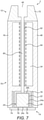
Figure 5 is a cross-sectional view along the line B-B inFigure 2 ; -
Figure 6 is a diagrammatic view of a vapour generating system according to a second embodiment of the present disclosure; and -
Figure 7 is a diagrammatic view of a vapour generating system according to a third embodiment of the present disclosure. - Embodiments of the present disclosure will now be described by way of example only and with reference to the accompanying drawings.
- Referring initially to
Figures 1 to 3 , there is shown diagrammatically a first embodiment of avapour generating system 1. Thevapour generating system 1 comprises avapour generating device 10 and avapour generating article 24. Thevapour generating device 10 has aproximal end 12 and adistal end 14 and comprises adevice body 16 which includes apower source 18 and acontroller 20 which may be configured to operate at high frequency. Thepower source 18 typically comprises one or more batteries which could, for example, be inductively rechargeable. - The
vapour generating device 10 is generally cylindrical and comprises a generally cylindricalvapour generating space 22 formed as a cavity in thedevice body 16 at theproximal end 12 of thevapour generating device 10. The cylindricalvapour generating space 22 is arranged to receive avapour generating material 26. In the illustrated embodiment, the cylindricalvapour generating space 22 is arranged to receive a correspondingly shaped generally cylindricalvapour generating article 24 containing thevapour generating material 26 and a heater in the form of one or more inductionheatable susceptors 28. Thevapour generating article 24 typically comprises a non-metallic cylindricalouter shell 24a and an air-permeable layer ormembrane vapour generating material 26 and allow air to flow through thevapour generating article 24. Thevapour generating article 24 is a disposable article which may, for example, contain tobacco as thevapour generating material 26. - The
vapour generating device 10 comprises ahelical induction coil 30 which has a circular cross-section and which extends around the cylindricalvapour generating space 22. Theinduction coil 30 can be energised by thepower source 18 andcontroller 20. Thecontroller 20 includes, amongst other electronic components, an inverter which is arranged to convert a direct current from thepower source 18 into an alternating highfrequency current for theinduction coil 30. - The
vapour generating device 10 includes an annularair flow passage 32 which surrounds theinduction coil 30 and which is positioned between theinduction coil 30 and a sealedannular cooling chamber 34. The annularair flow passage 32 communicates with thevapour generating space 22. - Referring to
Figures 2 and5 , thevapour generating device 10 comprises acover 36 which is removably mountable on thedevice body 16 at theproximal end 12. Thecover 36 comprises radially extendingair inlets 38 and a centralair flow passage 40 which deliver air into thevapour generating space 22, and more particularly into thevapour generating article 24 through the air-permeable membrane 24b. Thecover 32 also comprises a plurality of circumferentially spaced longitudinalair flow passages 42 which deliver a first vapour generated during use of thedevice 10 from the annularair flow passage 32 to anair outlet 44 where the first vapour can be inhaled by a user. - As will be understood by one of ordinary skill in the art, when the
induction coil 30 is energised, an alternating and time-varying electromagnetic field is produced. This couples with the one or more inductionheatable susceptors 28 and generates eddy currents and/or magnetic hysteresis losses in the one or more inductionheatable susceptors 28 causing them to heat up. The heat is then transferred from the one or more inductionheatable susceptors 28 to thevapour generating material 26, for example by conduction, radiation and convection. - The induction heatable susceptor(s) 28 can be in direct or indirect contact with the
vapour generating material 26, such that when the susceptor(s) 28 is/are inductively heated by theinduction coil 30, heat is transferred from the susceptor(s) 28 to thevapour generating material 26, to heat thevapour generating material 26 and thereby produce a first vapour. The vaporisation of thevapour generating material 26 is facilitated by the addition of air from the surrounding environment through theair inlets 38. The first vapour generated by heating thevapour generating material 26 exits thevapour generating space 22 through the annularair flow passage 32 and flows along the longitudinalair flow passages 42 to theair outlet 44 where it can be inhaled by a user of thedevice 10. The flow of air through thevapour generating space 22, i.e. from theair inlets 38, through thevapour generating space 22 and the annularair flow passage 32, and along the longitudinalair flow passages 42 in thecover 36 and out of theair outlet 44, can be aided by negative pressure created by a user drawing air from theair outlet 44 side of thedevice 10 and is shown diagrammatically by the arrows inFigure 2 . - Referring in particular to
Figures 1 ,3 and 4 , the sealedannular cooling chamber 34 is positioned between theinduction coil 30 and anouter surface 46 of thevapour generating device 10. The coolingchamber 34 comprises a liquid, such as water or ethyl-alcohol, which is vaporisable inside the coolingchamber 34 to form a second vapour and which is locked in the coolingchamber 34 both in its liquid and vapour form. More particularly, the liquid in the coolingchamber 34 absorbs heat, in particular through aninner wall 52 of the coolingchamber 34, from heated first vapour flowing through the annularair flow passage 32 and from other component parts of thedevice 10, such as theinduction coil 30 and induction heatable susceptor(s) 28, thereby removing heat from thedevice 10 as shown diagrammatically by thearrows 47 inFigure 4 . In order to promote the absorption of heat by the liquid in the coolingchamber 34, theinner wall 52 typically comprises a material which has good thermal conduction properties, for example a metal such as copper. - As the liquid in the cooling
chamber 34 absorbs heat and its temperature is raised above its boiling point, the liquid is vaporised (i.e. it evaporates) to form the second vapour. Heat is transferred from the second vapour to the surrounding ambient air via theouter surface 46 of thedevice 10 causing the second vapour to cool. As the second vapour cools, it condenses back into liquid form so that the liquid can again absorb heat from the heated first vapour and other component parts of thedevice 10. The transfer of heat from the second vapour takes place at a first position in the coolingchamber 34 which is proximate theouter surface 46 and the flow of the second vapour within the coolingchamber 34 is illustrated diagrammatically by thearrows 48. As the second vapour cools and condenses thereby returning to its liquid form, the liquid flows from the first position to a second position within the coolingchamber 34 which is proximate theinner wall 52, as illustrated diagrammatically by thearrows 50. - In order to promote the flow of the condensed liquid in the cooling
chamber 34 from the first position proximate theouter surface 46 to the second position proximate theinner wall 52, the coolingchamber 34 comprises acylindrical wick 54 which is positioned radially outwardly of theinner wall 52 and proximate to it. In some embodiments, thewick 54 comprises an electrically conductive copper mesh (schematically illustrated in the figures by means of the dashed line 54) and advantageously also acts as an electromagnetic shield for theinduction coil 30. It should be noted that theinner wall 52 can also act as an electromagnetic shield for theinduction coil 30, depending on the material from which it is fabricated. As mentioned above, theinner wall 52 may comprise copper which is an excellent material for electromagnetic shielding purposes as well as having excellent heat conductivity. - The
vapour generating device 10 also comprises anelectromagnetic shield layer 56 which is arranged outward of theinduction coil 30, between theinduction coil 30 and thewick 54. Theshield layer 56 is formed of a ferrimagnetic, non-electrically conductive material such as ferrite, Nickel Zinc Ferrite or mu-metal. In the embodiment illustrated inFigures 1 and2 , theelectromagnetic shield layer 56 comprises a substantially cylindrical sleeve, which is positioned radially outwardly of thehelical induction coil 30 so as to extend circumferentially around theinduction coil 30. - Referring now to
Figure 6 , there is shown a second embodiment of avapour generating system 2 which is similar to thevapour generating system 1 illustrated inFigures 1 to 5 and in which corresponding elements are designated using the same reference numerals. - The
vapour generating system 2 comprises avapour generating device 60 having anair inlet 62 which delivers air to thevapour generating space 22, and more particularly into thevapour generating article 24 through the air-permeable membrane 24c. Thevapour generating device 60 further comprises acover 64 which is removably mountable on thedevice body 16 at theproximal end 12. Thecover 64 comprises anair flow passage 66 which delivers a first vapour generated during use of thedevice 60 from thevapour generating space 22 to anair outlet 44 where the first vapour can be inhaled by a user. - The
vapour generating system 2 operates in the same manner as thevapour generating system 1 described above with reference toFigures 1 to 5 to heat thevapour generating material 26 and thereby generate a first vapour for inhalation by a user. - Referring now to
Figure 7 , there is shown a third embodiment of avapour generating system 3. Thevapour generating system 3 has some features in common with thevapour generating systems Figures 1 to 6 and corresponding elements are designated using the same reference numerals. - The
vapour generating system 3 comprises avapour generating device 70 having an integrally formedmouthpiece 72 at theproximal end 12 of thedevice 70 and in which the cylindricalvapour generating space 22 is located at thedistal end 14 of thedevice 70. Acover 74 for thevapour generating space 22 is removably mountable on thedevice body 16 at thedistal end 14. Thecover 74 includesair inlets 76 which allow air to flow into thevapour generating space 22. - The
vapour generating space 22 is arranged to receive avapour generating material 26. In the illustrated embodiment, the cylindricalvapour generating space 22 is arranged to receive a correspondingly shaped generally cylindricalvapour generating article 24 containing thevapour generating material 26. Thevapour generating article 24 typically comprises a non-metallic cylindricalouter shell 24a and an air-permeable layer ormembrane vapour generating material 26 and allow air to flow through thevapour generating article 24. Thevapour generating article 24 is a disposable article which may, for example, contain tobacco as thevapour generating material 26. - The
vapour generating device 70 comprises aresistive heater 78, for example comprising a resistive heating element, which is positioned radially outwardly of thevapour generating space 22 and which extends around thevapour generating space 22. - During operation of the
vapour generating system 3, an electric current is supplied to theresistive heater 78 causing it to heat up. The heat from theresistive heater 78 is transferred to thevapour generating material 26, for example by conduction, radiation and convection, to heat thevapour generating material 26 and thereby produce a first vapour. The vaporisation of thevapour generating material 26 is facilitated by the addition of air from the surrounding environment through theair inlets 76. - The first vapour generated by heating the
vapour generating material 26 then exits theheating compartment 22 through the air-permeable layer 24b, flows along anair flow passage 80 and through theair outlet 44 where it is inhaled by a user of thedevice 70 through themouthpiece 72. It will be understood that the flow of air through thevapour generating space 22 can be aided by negative pressure created by a user drawing air from the outlet side of thedevice 70 using themouthpiece 72. - The
vapour generating device 70 includes a sealedannular cooling chamber 34 which is positioned between theair flow passage 80 and theouter surface 46 of thevapour generating device 70. In the illustrated embodiment, theannular cooling chamber 34 extends longitudinally along substantially the whole of the length of theair flow passage 80, although it may extend along only a portion of theair flow passage 80 in other embodiments. As the heated first vapour flows along theair flow passage 80 during operation of thedevice 70, the liquid in the coolingchamber 34 absorbs heat from the first vapour through theinner wall 52, thereby cooling the first vapour in the manner described above with reference toFigures 1 to 6 and ensuring that the first vapour delivered via theair outlet 44 into the mouth of a user has optimum characteristics. - Although exemplary embodiments have been described in the preceding paragraphs, it should be understood that various modifications may be made to those embodiments without departing from the scope of the appended claims. Thus, the breadth and scope of the claims should not be limited to the above-described exemplary embodiments.
- Any combination of the above-described features in all possible variations thereof is encompassed by the present disclosure unless otherwise indicated herein or otherwise clearly contradicted by context.
- Unless the context clearly requires otherwise, throughout the description and the claims, the words "comprise", "comprising", and the like, are to be construed in an inclusive as opposed to an exclusive or exhaustive sense; that is to say, in the sense of "including, but not limited to".
Claims (15)
- A vapour generating system (1, 2, 3) comprising:a vapour generating space (22) for containing a vapour generating material (26);a heater (28, 78) for heating the vapour generating material to generate a first vapour;an air inlet (38, 62, 76), an air outlet (44) and an air flow passage (32, 66, 80) connecting the air inlet and the air outlet via the vapour generating space; andan outer surface (46);characterised in that the vapour generating system comprisesa sealed cooling chamber (34) comprising a liquid which is vaporised in use of the system to form a second vapour;wherein the cooling chamber is positioned between the heater and the outer surface and/or between the air flow passage and the outer surface.
- A vapour generating system according to any preceding claim, wherein the liquid has a boiling point less than approximately 60°C, preferably less than approximately 50°C, preferably less than approximately 40°C.
- A vapour generating system according to claim 1 or claim 2, wherein the cooling chamber (34) comprises a wick (54) to transfer the liquid from a first position in the cooling chamber to a second position in the cooling chamber.
- A vapour generating system according to claim 3, wherein the first position in the cooling chamber (34) is closer to the outer surface (46) than the second position in the cooling chamber.
- A vapour generating system according to claim 3 or claim 4, wherein the wick (54) comprises a mesh structure.
- A vapour generating system according to any preceding claim, wherein the heater comprises an induction heatable susceptor (28) and the vapour generating system comprises an induction coil (30) arranged to generate an alternating electromagnetic field for inductively heating the induction heatable susceptor, the cooling chamber (34) being positioned between the induction coil and the outer surface (46).
- A vapour generating system according to claim 6 when dependent on any of claims 3 to 5, wherein the wick (54) includes an electrically conductive material and is arranged to provide an electromagnetic shield for the induction coil (30).
- A vapour generating system according to claim 6 when dependent on any of claims 3 to 5 or according to claim 7, wherein the wick (54) extends substantially across at least one side of the induction coil (30).
- A vapour generating system according to claim 6 when dependent on any of claims 3 to 5 or according to claim 7 or claim 8, further comprising a ferrimagnetic, non-electrically conductive material (56) positioned between the wick (54) and the induction coil (30) and extending substantially across at least one side of the induction coil.
- A vapour generating system according to any of claims 6 to 9, wherein the air flow passage (32) is positioned between the induction coil (30) and the outer surface (46).
- A vapour generating system according to any of claims 6 to 10, wherein the cooling chamber (34) comprises an inner wall (52) proximate the induction coil (30), the inner wall (52) including a metal having good heat conductivity and electromagnetic shielding properties.
- A vapour generating system according to any preceding claim, wherein the cooling chamber (34) is positioned between the outer surface (46) and a portion of the air flow passage (80) connecting the vapour generating space (22) to the air outlet (44).
- A vapour generating device (10, 60) comprising:a vapour generating space (22) for receiving a vapour generating material (26);an induction coil (30) for heating the vapour generating material (26) to generate a first vapour;an air inlet (38, 62), an air outlet (44) and an air flow passage (32, 66) connecting the air inlet and the air outlet via the vapour generating space; andan outer surface (46);characterised in that the vapour generating device comprisesa sealed cooling chamber (34) comprising a liquid which is vaporised in use of the device to form a second vapour;wherein the cooling chamber is positioned between the induction coil and the outer surface and/or between the air flow passage and the outer surface.
- A vapour generating device according to claim 13, wherein the cooling chamber (34) comprises a wick (54) to transfer the liquid from a first position in the cooling chamber to a second position in the cooling chamber, the wick including an electrically conductive material and being arranged to provide an electromagnetic shield for the induction coil (30).
- A vapour generating device (70) comprising:a vapour generating space (22) for receiving a vapour generating material (26);a resistive heater (78) for heating the vapour generating material to generate a first vapour;an air inlet (76), an air outlet (44) and an air flow passage (80) connecting the air inlet and the air outlet via the vapour generating space; andan outer surface (46);characterised in that the vapour generating device comprisesa sealed cooling chamber (34) comprising a liquid which is vaporised in use of the device to form a second vapour;wherein the cooling chamber (34) is positioned between the resistive heater and the outer surface and/or between the air flow passage and the outer surface.
Priority Applications (1)
| Application Number | Priority Date | Filing Date | Title |
|---|---|---|---|
| PL19725282T PL3784079T3 (en) | 2018-04-27 | 2019-04-25 | Vapour generating system |
Applications Claiming Priority (2)
| Application Number | Priority Date | Filing Date | Title |
|---|---|---|---|
| EP18169766 | 2018-04-27 | ||
| PCT/EP2019/060564 WO2019207023A1 (en) | 2018-04-27 | 2019-04-25 | Vapour generating system |
Publications (2)
| Publication Number | Publication Date |
|---|---|
| EP3784079A1 EP3784079A1 (en) | 2021-03-03 |
| EP3784079B1 true EP3784079B1 (en) | 2022-02-23 |
Family
ID=62089601
Family Applications (1)
| Application Number | Title | Priority Date | Filing Date |
|---|---|---|---|
| EP19725282.8A Active EP3784079B1 (en) | 2018-04-27 | 2019-04-25 | Vapour generating system |
Country Status (10)
| Country | Link |
|---|---|
| US (1) | US20200404968A1 (en) |
| EP (1) | EP3784079B1 (en) |
| JP (1) | JP7232262B2 (en) |
| KR (1) | KR102488320B1 (en) |
| CN (1) | CN112105270A (en) |
| EA (1) | EA202092575A1 (en) |
| ES (1) | ES2909823T3 (en) |
| PL (1) | PL3784079T3 (en) |
| TW (1) | TW201945665A (en) |
| WO (1) | WO2019207023A1 (en) |
Families Citing this family (8)
| Publication number | Priority date | Publication date | Assignee | Title |
|---|---|---|---|---|
| CA2939641A1 (en) * | 2014-04-30 | 2015-11-05 | Philip Morris Products S.A. | A container having a heater for an aerosol-generating device, and aerosol-generating device |
| EP4064912B1 (en) * | 2019-11-26 | 2024-01-03 | JT International SA | Aerosol generating system |
| KR102587103B1 (en) * | 2020-12-01 | 2023-10-11 | 주식회사 케이티앤지 | Aerosol generating device |
| WO2023042364A1 (en) * | 2021-09-17 | 2023-03-23 | 日本たばこ産業株式会社 | Aerosol generation system |
| WO2023111359A1 (en) * | 2021-12-17 | 2023-06-22 | Nicoventures Trading Limited | Electronic vapour provision device |
| WO2023118272A1 (en) * | 2021-12-22 | 2023-06-29 | Jt International Sa | An induction heating assembly for an aerosol generating device |
| CN216875047U (en) * | 2021-12-31 | 2022-07-05 | 海南摩尔兄弟科技有限公司 | Heating atomization device |
| WO2024033848A1 (en) * | 2022-08-10 | 2024-02-15 | AMP Innovations Inc. | Vaporizer cartridge |
Family Cites Families (18)
| Publication number | Priority date | Publication date | Assignee | Title |
|---|---|---|---|---|
| JPS61123059A (en) * | 1984-11-20 | 1986-06-10 | Tokico Ltd | Magnetic disc device |
| CN1131892C (en) * | 1998-08-03 | 2003-12-24 | 东京电子株式会社 | ESRF chamber cooling system and process |
| US20030136550A1 (en) * | 2002-01-24 | 2003-07-24 | Global Win Technology | Heat sink adapted for dissipating heat from a semiconductor device |
| TWI236870B (en) * | 2004-06-29 | 2005-07-21 | Ind Tech Res Inst | Heat dissipation apparatus with microstructure layer and manufacture method thereof |
| CN100437005C (en) * | 2005-07-08 | 2008-11-26 | 富准精密工业(深圳)有限公司 | Flat type heat-pipe |
| CN101603791B (en) * | 2009-07-01 | 2010-10-20 | 哈尔滨工程大学 | Capillary cooler |
| PT2306102E (en) * | 2009-09-29 | 2013-05-03 | Hemera En Renovables Espana S L U | Device and method for cooling down and/or warming up fluid |
| CN101900506A (en) * | 2010-01-15 | 2010-12-01 | 富瑞精密组件(昆山)有限公司 | Flat and thin heat guide pipe |
| US20110193479A1 (en) * | 2010-02-08 | 2011-08-11 | Nilssen Ole K | Evaporation Cooled Lamp |
| CN103610231B (en) * | 2013-11-01 | 2016-01-20 | 深圳市杰仕博科技有限公司 | Hookah for electronic cigarette |
| US20150181935A1 (en) * | 2013-12-27 | 2015-07-02 | British American Tobacco (Investments) Limited | Apparatus for Heating Smokeable Material |
| TWI661782B (en) * | 2014-05-21 | 2019-06-11 | 瑞士商菲利浦莫里斯製品股份有限公司 | Electrically heated aerosol-generating system,electrically heated aerosol-generating deviceand method of generating an aerosol |
| GB201418817D0 (en) * | 2014-10-22 | 2014-12-03 | British American Tobacco Co | Apparatus and method for generating an inhalable medium, and a cartridge for use therewith |
| GB201418771D0 (en) * | 2014-10-22 | 2014-12-03 | British American Tobacco Co | Methods of manufacturing a double walled tube |
| WO2017114760A1 (en) * | 2015-12-31 | 2017-07-06 | Philip Morris Products S.A. | Breakable aerosol generating article |
| US10772355B2 (en) * | 2016-07-29 | 2020-09-15 | Altria Client Services Llc | Aerosol-generating system including a heated gel container |
| RU2739014C2 (en) * | 2016-09-28 | 2020-12-21 | Филип Моррис Продактс С.А. | Portable extinguishing device for aerosol-generating article |
| JP7317837B2 (en) * | 2018-01-15 | 2023-07-31 | フィリップ・モーリス・プロダクツ・ソシエテ・アノニム | Shisha device with cooling to enhance aerosol characteristics |
-
2019
- 2019-04-25 CN CN201980027944.9A patent/CN112105270A/en active Pending
- 2019-04-25 US US16/978,300 patent/US20200404968A1/en not_active Abandoned
- 2019-04-25 TW TW108114438A patent/TW201945665A/en unknown
- 2019-04-25 WO PCT/EP2019/060564 patent/WO2019207023A1/en active Application Filing
- 2019-04-25 KR KR1020207034059A patent/KR102488320B1/en active IP Right Grant
- 2019-04-25 ES ES19725282T patent/ES2909823T3/en active Active
- 2019-04-25 JP JP2020558891A patent/JP7232262B2/en active Active
- 2019-04-25 EP EP19725282.8A patent/EP3784079B1/en active Active
- 2019-04-25 EA EA202092575A patent/EA202092575A1/en unknown
- 2019-04-25 PL PL19725282T patent/PL3784079T3/en unknown
Also Published As
| Publication number | Publication date |
|---|---|
| TW201945665A (en) | 2019-12-01 |
| ES2909823T3 (en) | 2022-05-10 |
| US20200404968A1 (en) | 2020-12-31 |
| EP3784079A1 (en) | 2021-03-03 |
| KR20210018812A (en) | 2021-02-18 |
| JP2021521813A (en) | 2021-08-30 |
| WO2019207023A1 (en) | 2019-10-31 |
| KR102488320B1 (en) | 2023-01-17 |
| PL3784079T3 (en) | 2022-05-30 |
| JP7232262B2 (en) | 2023-03-02 |
| EA202092575A1 (en) | 2021-02-02 |
| CN112105270A (en) | 2020-12-18 |
Similar Documents
| Publication | Publication Date | Title |
|---|---|---|
| EP3784079B1 (en) | Vapour generating system | |
| EP4216668B1 (en) | Induction heating assembly for a vapour generating device | |
| EP3731668B1 (en) | Induction heating assembly for a vapour generating device | |
| WO2019224078A1 (en) | An inhalation system, an inhalation device and a vapour generating article | |
| WO2021099231A1 (en) | An aerosol generating article and an aerosol generating system | |
| US20210259319A1 (en) | Inhalation System, An Inhalation Device And A Vapour Generating Article | |
| EP4064912B1 (en) | Aerosol generating system | |
| EA042776B1 (en) | STEAM GENERATING SYSTEM |
Legal Events
| Date | Code | Title | Description |
|---|---|---|---|
| STAA | Information on the status of an ep patent application or granted ep patent |
Free format text: STATUS: UNKNOWN |
|
| STAA | Information on the status of an ep patent application or granted ep patent |
Free format text: STATUS: THE INTERNATIONAL PUBLICATION HAS BEEN MADE |
|
| STAA | Information on the status of an ep patent application or granted ep patent |
Free format text: STATUS: THE INTERNATIONAL PUBLICATION HAS BEEN MADE |
|
| PUAI | Public reference made under article 153(3) epc to a published international application that has entered the european phase |
Free format text: ORIGINAL CODE: 0009012 |
|
| STAA | Information on the status of an ep patent application or granted ep patent |
Free format text: STATUS: REQUEST FOR EXAMINATION WAS MADE |
|
| 17P | Request for examination filed |
Effective date: 20201120 |
|
| AK | Designated contracting states |
Kind code of ref document: A1 Designated state(s): AL AT BE BG CH CY CZ DE DK EE ES FI FR GB GR HR HU IE IS IT LI LT LU LV MC MK MT NL NO PL PT RO RS SE SI SK SM TR |
|
| AX | Request for extension of the european patent |
Extension state: BA ME |
|
| DAV | Request for validation of the european patent (deleted) | ||
| DAX | Request for extension of the european patent (deleted) | ||
| GRAP | Despatch of communication of intention to grant a patent |
Free format text: ORIGINAL CODE: EPIDOSNIGR1 |
|
| STAA | Information on the status of an ep patent application or granted ep patent |
Free format text: STATUS: GRANT OF PATENT IS INTENDED |
|
| INTG | Intention to grant announced |
Effective date: 20210923 |
|
| GRAS | Grant fee paid |
Free format text: ORIGINAL CODE: EPIDOSNIGR3 |
|
| GRAA | (expected) grant |
Free format text: ORIGINAL CODE: 0009210 |
|
| STAA | Information on the status of an ep patent application or granted ep patent |
Free format text: STATUS: THE PATENT HAS BEEN GRANTED |
|
| AK | Designated contracting states |
Kind code of ref document: B1 Designated state(s): AL AT BE BG CH CY CZ DE DK EE ES FI FR GB GR HR HU IE IS IT LI LT LU LV MC MK MT NL NO PL PT RO RS SE SI SK SM TR |
|
| REG | Reference to a national code |
Ref country code: GB Ref legal event code: FG4D |
|
| REG | Reference to a national code |
Ref country code: CH Ref legal event code: EP |
|
| REG | Reference to a national code |
Ref country code: DE Ref legal event code: R096 Ref document number: 602019011913 Country of ref document: DE |
|
| REG | Reference to a national code |
Ref country code: AT Ref legal event code: REF Ref document number: 1469768 Country of ref document: AT Kind code of ref document: T Effective date: 20220315 |
|
| REG | Reference to a national code |
Ref country code: IE Ref legal event code: FG4D |
|
| REG | Reference to a national code |
Ref country code: ES Ref legal event code: FG2A Ref document number: 2909823 Country of ref document: ES Kind code of ref document: T3 Effective date: 20220510 |
|
| REG | Reference to a national code |
Ref country code: NL Ref legal event code: FP |
|
| REG | Reference to a national code |
Ref country code: LT Ref legal event code: MG9D |
|
| PGFP | Annual fee paid to national office [announced via postgrant information from national office to epo] |
Ref country code: NL Payment date: 20220420 Year of fee payment: 4 |
|
| REG | Reference to a national code |
Ref country code: AT Ref legal event code: MK05 Ref document number: 1469768 Country of ref document: AT Kind code of ref document: T Effective date: 20220223 |
|
| PG25 | Lapsed in a contracting state [announced via postgrant information from national office to epo] |
Ref country code: SE Free format text: LAPSE BECAUSE OF FAILURE TO SUBMIT A TRANSLATION OF THE DESCRIPTION OR TO PAY THE FEE WITHIN THE PRESCRIBED TIME-LIMIT Effective date: 20220223 Ref country code: RS Free format text: LAPSE BECAUSE OF FAILURE TO SUBMIT A TRANSLATION OF THE DESCRIPTION OR TO PAY THE FEE WITHIN THE PRESCRIBED TIME-LIMIT Effective date: 20220223 Ref country code: PT Free format text: LAPSE BECAUSE OF FAILURE TO SUBMIT A TRANSLATION OF THE DESCRIPTION OR TO PAY THE FEE WITHIN THE PRESCRIBED TIME-LIMIT Effective date: 20220623 Ref country code: NO Free format text: LAPSE BECAUSE OF FAILURE TO SUBMIT A TRANSLATION OF THE DESCRIPTION OR TO PAY THE FEE WITHIN THE PRESCRIBED TIME-LIMIT Effective date: 20220523 Ref country code: LT Free format text: LAPSE BECAUSE OF FAILURE TO SUBMIT A TRANSLATION OF THE DESCRIPTION OR TO PAY THE FEE WITHIN THE PRESCRIBED TIME-LIMIT Effective date: 20220223 Ref country code: HR Free format text: LAPSE BECAUSE OF FAILURE TO SUBMIT A TRANSLATION OF THE DESCRIPTION OR TO PAY THE FEE WITHIN THE PRESCRIBED TIME-LIMIT Effective date: 20220223 Ref country code: BG Free format text: LAPSE BECAUSE OF FAILURE TO SUBMIT A TRANSLATION OF THE DESCRIPTION OR TO PAY THE FEE WITHIN THE PRESCRIBED TIME-LIMIT Effective date: 20220523 |
|
| PG25 | Lapsed in a contracting state [announced via postgrant information from national office to epo] |
Ref country code: LV Free format text: LAPSE BECAUSE OF FAILURE TO SUBMIT A TRANSLATION OF THE DESCRIPTION OR TO PAY THE FEE WITHIN THE PRESCRIBED TIME-LIMIT Effective date: 20220223 Ref country code: GR Free format text: LAPSE BECAUSE OF FAILURE TO SUBMIT A TRANSLATION OF THE DESCRIPTION OR TO PAY THE FEE WITHIN THE PRESCRIBED TIME-LIMIT Effective date: 20220524 Ref country code: FI Free format text: LAPSE BECAUSE OF FAILURE TO SUBMIT A TRANSLATION OF THE DESCRIPTION OR TO PAY THE FEE WITHIN THE PRESCRIBED TIME-LIMIT Effective date: 20220223 Ref country code: AT Free format text: LAPSE BECAUSE OF FAILURE TO SUBMIT A TRANSLATION OF THE DESCRIPTION OR TO PAY THE FEE WITHIN THE PRESCRIBED TIME-LIMIT Effective date: 20220223 |
|
| PG25 | Lapsed in a contracting state [announced via postgrant information from national office to epo] |
Ref country code: IS Free format text: LAPSE BECAUSE OF FAILURE TO SUBMIT A TRANSLATION OF THE DESCRIPTION OR TO PAY THE FEE WITHIN THE PRESCRIBED TIME-LIMIT Effective date: 20220623 |
|
| PG25 | Lapsed in a contracting state [announced via postgrant information from national office to epo] |
Ref country code: SM Free format text: LAPSE BECAUSE OF FAILURE TO SUBMIT A TRANSLATION OF THE DESCRIPTION OR TO PAY THE FEE WITHIN THE PRESCRIBED TIME-LIMIT Effective date: 20220223 Ref country code: SK Free format text: LAPSE BECAUSE OF FAILURE TO SUBMIT A TRANSLATION OF THE DESCRIPTION OR TO PAY THE FEE WITHIN THE PRESCRIBED TIME-LIMIT Effective date: 20220223 Ref country code: RO Free format text: LAPSE BECAUSE OF FAILURE TO SUBMIT A TRANSLATION OF THE DESCRIPTION OR TO PAY THE FEE WITHIN THE PRESCRIBED TIME-LIMIT Effective date: 20220223 Ref country code: EE Free format text: LAPSE BECAUSE OF FAILURE TO SUBMIT A TRANSLATION OF THE DESCRIPTION OR TO PAY THE FEE WITHIN THE PRESCRIBED TIME-LIMIT Effective date: 20220223 Ref country code: DK Free format text: LAPSE BECAUSE OF FAILURE TO SUBMIT A TRANSLATION OF THE DESCRIPTION OR TO PAY THE FEE WITHIN THE PRESCRIBED TIME-LIMIT Effective date: 20220223 Ref country code: CZ Free format text: LAPSE BECAUSE OF FAILURE TO SUBMIT A TRANSLATION OF THE DESCRIPTION OR TO PAY THE FEE WITHIN THE PRESCRIBED TIME-LIMIT Effective date: 20220223 |
|
| REG | Reference to a national code |
Ref country code: DE Ref legal event code: R097 Ref document number: 602019011913 Country of ref document: DE |
|
| PG25 | Lapsed in a contracting state [announced via postgrant information from national office to epo] |
Ref country code: AL Free format text: LAPSE BECAUSE OF FAILURE TO SUBMIT A TRANSLATION OF THE DESCRIPTION OR TO PAY THE FEE WITHIN THE PRESCRIBED TIME-LIMIT Effective date: 20220223 |
|
| PLBE | No opposition filed within time limit |
Free format text: ORIGINAL CODE: 0009261 |
|
| STAA | Information on the status of an ep patent application or granted ep patent |
Free format text: STATUS: NO OPPOSITION FILED WITHIN TIME LIMIT |
|
| REG | Reference to a national code |
Ref country code: BE Ref legal event code: MM Effective date: 20220430 |
|
| PG25 | Lapsed in a contracting state [announced via postgrant information from national office to epo] |
Ref country code: MC Free format text: LAPSE BECAUSE OF FAILURE TO SUBMIT A TRANSLATION OF THE DESCRIPTION OR TO PAY THE FEE WITHIN THE PRESCRIBED TIME-LIMIT Effective date: 20220223 Ref country code: LU Free format text: LAPSE BECAUSE OF NON-PAYMENT OF DUE FEES Effective date: 20220425 |
|
| 26N | No opposition filed |
Effective date: 20221124 |
|
| PG25 | Lapsed in a contracting state [announced via postgrant information from national office to epo] |
Ref country code: SI Free format text: LAPSE BECAUSE OF FAILURE TO SUBMIT A TRANSLATION OF THE DESCRIPTION OR TO PAY THE FEE WITHIN THE PRESCRIBED TIME-LIMIT Effective date: 20220223 Ref country code: BE Free format text: LAPSE BECAUSE OF NON-PAYMENT OF DUE FEES Effective date: 20220430 |
|
| PG25 | Lapsed in a contracting state [announced via postgrant information from national office to epo] |
Ref country code: IE Free format text: LAPSE BECAUSE OF NON-PAYMENT OF DUE FEES Effective date: 20220425 |
|
| P01 | Opt-out of the competence of the unified patent court (upc) registered |
Effective date: 20230518 |
|
| PGFP | Annual fee paid to national office [announced via postgrant information from national office to epo] |
Ref country code: IT Payment date: 20230426 Year of fee payment: 5 Ref country code: FR Payment date: 20230424 Year of fee payment: 5 Ref country code: ES Payment date: 20230627 Year of fee payment: 5 Ref country code: DE Payment date: 20230420 Year of fee payment: 5 Ref country code: CH Payment date: 20230502 Year of fee payment: 5 |
|
| PGFP | Annual fee paid to national office [announced via postgrant information from national office to epo] |
Ref country code: PL Payment date: 20220415 Year of fee payment: 4 |
|
| PGFP | Annual fee paid to national office [announced via postgrant information from national office to epo] |
Ref country code: GB Payment date: 20230419 Year of fee payment: 5 |
|
| REG | Reference to a national code |
Ref country code: NL Ref legal event code: MM Effective date: 20230501 |
|
| PG25 | Lapsed in a contracting state [announced via postgrant information from national office to epo] |
Ref country code: NL Free format text: LAPSE BECAUSE OF NON-PAYMENT OF DUE FEES Effective date: 20230501 |