EP3783959B1 - Verfahren und vorrichtung zur steuerung von netzwerkzugang - Google Patents
Verfahren und vorrichtung zur steuerung von netzwerkzugang Download PDFInfo
- Publication number
- EP3783959B1 EP3783959B1 EP18915324.0A EP18915324A EP3783959B1 EP 3783959 B1 EP3783959 B1 EP 3783959B1 EP 18915324 A EP18915324 A EP 18915324A EP 3783959 B1 EP3783959 B1 EP 3783959B1
- Authority
- EP
- European Patent Office
- Prior art keywords
- carrier
- configuration information
- applicable
- information
- target
- Prior art date
- Legal status (The legal status is an assumption and is not a legal conclusion. Google has not performed a legal analysis and makes no representation as to the accuracy of the status listed.)
- Active
Links
Images


Classifications
-
- H—ELECTRICITY
- H04—ELECTRIC COMMUNICATION TECHNIQUE
- H04W—WIRELESS COMMUNICATION NETWORKS
- H04W72/00—Local resource management
- H04W72/02—Selection of wireless resources by user or terminal
-
- H—ELECTRICITY
- H04—ELECTRIC COMMUNICATION TECHNIQUE
- H04W—WIRELESS COMMUNICATION NETWORKS
- H04W48/00—Access restriction; Network selection; Access point selection
- H04W48/02—Access restriction performed under specific conditions
- H04W48/06—Access restriction performed under specific conditions based on traffic conditions
-
- H—ELECTRICITY
- H04—ELECTRIC COMMUNICATION TECHNIQUE
- H04B—TRANSMISSION
- H04B17/00—Monitoring; Testing
- H04B17/30—Monitoring; Testing of propagation channels
- H04B17/309—Measuring or estimating channel quality parameters
- H04B17/318—Received signal strength
- H04B17/328—Reference signal received power [RSRP]; Reference signal received quality [RSRQ]
-
- H—ELECTRICITY
- H04—ELECTRIC COMMUNICATION TECHNIQUE
- H04L—TRANSMISSION OF DIGITAL INFORMATION, e.g. TELEGRAPHIC COMMUNICATION
- H04L5/00—Arrangements affording multiple use of the transmission path
- H04L5/0001—Arrangements for dividing the transmission path
- H04L5/0003—Two-dimensional division
- H04L5/0005—Time-frequency
- H04L5/0007—Time-frequency the frequencies being orthogonal, e.g. OFDM(A) or DMT
- H04L5/001—Time-frequency the frequencies being orthogonal, e.g. OFDM(A) or DMT the frequencies being arranged in component carriers
-
- H—ELECTRICITY
- H04—ELECTRIC COMMUNICATION TECHNIQUE
- H04L—TRANSMISSION OF DIGITAL INFORMATION, e.g. TELEGRAPHIC COMMUNICATION
- H04L5/00—Arrangements affording multiple use of the transmission path
- H04L5/003—Arrangements for allocating sub-channels of the transmission path
- H04L5/0053—Allocation of signalling, i.e. of overhead other than pilot signals
-
- H—ELECTRICITY
- H04—ELECTRIC COMMUNICATION TECHNIQUE
- H04W—WIRELESS COMMUNICATION NETWORKS
- H04W48/00—Access restriction; Network selection; Access point selection
- H04W48/16—Discovering, processing access restriction or access information
-
- H—ELECTRICITY
- H04—ELECTRIC COMMUNICATION TECHNIQUE
- H04W—WIRELESS COMMUNICATION NETWORKS
- H04W72/00—Local resource management
- H04W72/04—Wireless resource allocation
- H04W72/044—Wireless resource allocation based on the type of the allocated resource
- H04W72/0453—Resources in frequency domain, e.g. a carrier in FDMA
-
- H—ELECTRICITY
- H04—ELECTRIC COMMUNICATION TECHNIQUE
- H04W—WIRELESS COMMUNICATION NETWORKS
- H04W72/00—Local resource management
- H04W72/12—Wireless traffic scheduling
- H04W72/1263—Mapping of traffic onto schedule, e.g. scheduled allocation or multiplexing of flows
- H04W72/1268—Mapping of traffic onto schedule, e.g. scheduled allocation or multiplexing of flows of uplink data flows
-
- H—ELECTRICITY
- H04—ELECTRIC COMMUNICATION TECHNIQUE
- H04W—WIRELESS COMMUNICATION NETWORKS
- H04W72/00—Local resource management
- H04W72/20—Control channels or signalling for resource management
- H04W72/23—Control channels or signalling for resource management in the downlink direction of a wireless link, i.e. towards a terminal
-
- H—ELECTRICITY
- H04—ELECTRIC COMMUNICATION TECHNIQUE
- H04W—WIRELESS COMMUNICATION NETWORKS
- H04W72/00—Local resource management
- H04W72/50—Allocation or scheduling criteria for wireless resources
- H04W72/52—Allocation or scheduling criteria for wireless resources based on load
-
- H—ELECTRICITY
- H04—ELECTRIC COMMUNICATION TECHNIQUE
- H04W—WIRELESS COMMUNICATION NETWORKS
- H04W72/00—Local resource management
- H04W72/50—Allocation or scheduling criteria for wireless resources
- H04W72/535—Allocation or scheduling criteria for wireless resources based on resource usage policies
-
- H—ELECTRICITY
- H04—ELECTRIC COMMUNICATION TECHNIQUE
- H04W—WIRELESS COMMUNICATION NETWORKS
- H04W74/00—Wireless channel access
- H04W74/002—Transmission of channel access control information
- H04W74/006—Transmission of channel access control information in the downlink, i.e. towards the terminal
Definitions
- the present disclosure relates to the technical field of communications, and in particular to a method and an apparatus for controlling network access.
- 5G New Radio
- 5G networks allow a large number of different types of user equipment to access the networks, and support a large variety of traffic types.
- the 5G network inherits the AC (Access Control) barring mechanism of the 4G network LTE (Long Term Evolutions) system to control UE access to the network.
- the basic access process is: when user equipment needs to initiate a traffic request, one or more access identities and an access category are provided by NAS (Non Access Stratum) to AS (Access Stratum), and used for AC barring to decide whether the UE can initiate the traffic request.
- NAS Non Access Stratum
- AS Access Stratum
- CMCC "Considerations on support of supplementary uplink frequency", 3GPP DRAFT; R2-1711824 CONSIDERATIONS ON SUPPORT OF SUPPLEMENTARY UPLINK FREQUENCY, 3RD GENERATION PARTNERSHIP PROJECT (3GPP), MOBILE COMPETENCE CENTRE; 650, ROUTE DES LUCIOLES; F-06921 SOPHIA-ANTIP, vol. RAN WG2, no.
- XP051355856 describes the configuration of SUL parameters, specifically, the uplink configuration parameters of SUL include RACH configuration, UL power control configuration, threshold for UL selection, UL carrier frequency, UL bandwidth, PRACH configuration, PUSCH configuration, PUCCH configuration, SRS configuration, and UL cyclic prefix configuration.
- ZTE ET AL "Discussion on SUL carrier", 3GPP DRAFT; R2-1711841 DISCUSSION ON SUL CARRIER V2, 3RD GENERATION PARTNERSHIP PROJECT (3GPP), MOBILE COMPETENCE CENTRE; 650, ROUTE DES LUCIOLES; F-06921 SOPHIA-ANTIPOLIS CEDEX; FRANCE, vol. RAN WG1, no. Prague, Czech; 20171009 - 201710138 October 2017 (2017-10-08), XP051355889 , discusses the following aspects: 2.1 Initial access procedure, and 2.2. After initial access procedure.
- VIVO "Other aspects on carrier aggregation", 3GPP DRAFT; R1-1719801 OTHER ASPECTS ON CARRIER AGGREGATION_FINAL, 3RD GENERATION PARTNERSHIP PROJECT (3GPP), MOBILE COMPETENCE CENTRE ; 650, ROUTE DES LUCIOLES ; F-06921 SOPHIA-ANTIPOLIS CEDEX ; FRAN, vol. RAN WG1, no. Reno, USA; 20171127 - 20171201 18 November 2017 (2017-11-18), XP051369544 , discusses the following aspects: 2.1 SUL scheduling, 2.2 Fallback operation, 2.3 Random access response, 2.4 Group-common PDCCH, 2.5 UL carrier switching time, and 3.
- NOKIA ET AL "Access attempt categorization and barring check", 3GPP DRAFT; R2-1801054 ACCESS ATTEMPT CATEGORIZATION AND BARRING CHECK, 3RD GENERATION PARTNERSHIP PROJECT (3GPP), MOBILE COMPETENCE CENTRE; 650, ROUTE DES LUCIOLES ; F-06921 SOPHIA-ANTIPOLIS CEDEX ; vol. RAN WG2, no. Vancouver, Canada; 20180122 - 20180126 12 January 2018 (2018-01-12), XP051386548 , discloses that the gNB broadcasts barring configuration associated with Access Categories and Access Identities, with at least some indication in minimum system information.
- examples of the present disclosure provide a method and an apparatus for controlling network access, so as to improve the uplink coverage capability of the NR system and realize load control on the SUL carrier.
- a method for controlling network access includes:
- determining the target type carrier carrying traffic to be transmitted including:
- determining the target type carrier in response to that the user equipment is currently in a connected state, determining the target type carrier by at least one of the following:
- determining the target type carrier according to the RSRP includes:
- determining the target type carrier according to the latest historical scheduling information includes:
- determining the target AC configuration information applicable to the target type carrier includes:
- determining the target AC configuration information applicable to the target type carrier according to the AC configuration information issued by the base station includes:
- determining the target AC configuration information applicable to the target type carrier according to the AC configuration information issued by the base station includes:
- the carrier applicable information further includes: an effective time range indicating an allowable time range in which the sub-configuration information is applicable to a preset uplink carrier;
- a method for controlling network access is provided, the method applicable to a base station, and including:
- sending the AC configuration information to the user equipment includes:
- sending the AC configuration information to the user equipment includes:
- the carrier applicable information further includes: an effective time range indicating an allowable time range in which the sub-configuration information is applicable to a preset uplink carrier.
- the method further includes: sending uplink carrier indication information to the user equipment, wherein the uplink carrier indication information is configured to inform the user equipment to initiate a network access request through a specified type of uplink carrier, wherein the specified type of uplink carrier is a SUL carrier or a non-SUL carrier.
- an apparatus for controlling network access is provided.
- the apparatus is provided in a user equipment, and includes:
- the uplink carrier determining module in response to that the user equipment is currently in any one of an inactive state, idle state, or out-of-synchronization state in a connected state, includes:
- the uplink carrier determining module in response to that the user equipment is currently in a connected state, includes any one of the following:
- the first determining submodule includes:
- the third determining submodule includes:
- the configuration information determining module includes:
- the configuration information determining module includes:
- the carrier applicable information further includes: an effective time range indicating an allowable time range in which the sub-configuration information is applicable to a preset uplink carrier;
- an apparatus for controlling network access is provided.
- the apparatus is provided in a base station, and includes:
- the sending module includes:
- the apparatus further includes: an indication information sending module configured to send uplink carrier indication information to the user equipment, wherein the uplink carrier indication information is configured to inform the user equipment to initiate a network access request through a specified type of uplink carrier, and the specified type of uplink carrier is a SUL carrier or a non-SUL carrier.
- an indication information sending module configured to send uplink carrier indication information to the user equipment, wherein the uplink carrier indication information is configured to inform the user equipment to initiate a network access request through a specified type of uplink carrier, and the specified type of uplink carrier is a SUL carrier or a non-SUL carrier.
- a non-transitory computer-readable storage medium having computer instructions stored thereon wherein, when the instructions are executed by a processor, the steps of the method in the first aspect.
- a non-transitory computer-readable storage medium having computer instructions stored thereon wherein, when the instructions are executed by a processor, the steps of the method in the second aspect are performed.
- an apparatus for controlling network access including:
- an apparatus for controlling network access including:
- the UE can use two uplink carriers, namely, the non-SUL carrier and the SUL carrier to initiate a network access request to the base station to improve the uplink coverage performance of the 5G NR system.
- the corresponding AC configuration information issued by the base station can be used to perform the AC process, and the load control of the two uplink carriers can be performed flexibly and effectively to prevent the UE from blindly initiating a traffic request through the currently selected target uplink carrier, causing the target uplink carrier load on the network side to be too high, and causing channel congestion. It can ensure the reliability of information transmission on each uplink carrier, improve data transmission efficiency, and improve the user experience of the 5G NR system.
- first, second, third, and the like may be used in the present disclosure to describe various information, such information should not be limited to these terms. These terms are only used to distinguish one category of information from another. For example, without departing from the scope of the present disclosure, first information may be referred as second information; and similarly, second information may also be referred as first information.
- first information may be referred as second information; and similarly, second information may also be referred as first information.
- word “if” as used herein may be interpreted as “when” or “upon” or “in response to determining”.
- the "network” and “system” appearing in the embodiments of the present disclosure express the same concept, and the communication system is the communication network.
- a SUL (Supplementary Uplink) feature is introduced in a 5G NR system, that is, one downlink carrier and two uplink carriers are configured in the same cell to improve uplink covering ability of the system.
- the above two uplink carriers include a SUL carrier (or secondary uplink carrier) and a non-SUL carrier (or primary uplink carrier).
- the frequency band to which the SUL carrier belongs is lower than the frequency band to which the non-SUL carrier belongs.
- the SUL carrier of the NR system can be in the same frequency band as the uplink carrier of the LTE system. Referring to the diagram of distribution of cell carriers shown in FIG.
- the non-SUL carrier allocated by the base station for a cell is in the same frequency range as the downlink DL carrier, and is located in a higher frequency band.
- the SUL carrier does not belong to the same frequency range as the DL (Downlink) carrier, and is located in a lower frequency band.
- the present disclosure provides a method for controlling network access.
- the method can include the following steps.
- a target type carrier carrying the traffic to be transmitted is determined, where the target type carrier includes a SUL carrier or a non-SUL carrier.
- a UE in a cell when a UE in a cell needs to initiate a traffic request to the network, it can first determine an available uplink carrier, that is, the target type carrier, based on the current state information of the UE.
- the target type carrier involved in the present disclosure refers to an uplink carrier, that is, a carrier that carries uplink information
- the uplink information refers to information sent by the UE to the base station.
- the state information of the UE can include: an inactive state, an idle state, and a connected state.
- the connected state of the UE can also include two sub-states: a synchronized state and an out-of-synchronization state.
- the inactive state and the idle state indicate that the UE is not currently connected to the network.
- the synchronized state in the connected state indicates that the UE is currently connected to the network and is uplink synchronized, is configured with PUCCH resources, and can be normally scheduled.
- the out-of-synchronization state in the connected state indicates that the UE is currently accessing the network but is out-of-synchronization in the uplink, has no PUCCH resources, and cannot be normally scheduled.
- the UE can determine the target type carrier in at least one of the following implementations.
- the target type carrier may be determined according to RSRP (Reference Signal Receiving Power).
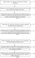
- step 11 can include step 1101 - step 1103.
- the detected reference signal received power RSRP is compared with a preset power threshold.
- the UE can detect the RSRP value in real time or in a preset detection period, and compare it with a preset power threshold. If the RSRP value is greater than or equal to the preset power threshold, the non-SUL carrier is determined as the target type carrier. That is, it is determined that the UE can initiate an RA request or traffic request to the base station through a non-SUL carrier. Otherwise, the following step 1102 is performed.
- the SUL carrier is determined as a target type carrier.
- the UE can determine to initiate an RA request or a traffic request to the base station through the SUL carrier.
- the non-SUL carrier is determined as a target type carrier.
- the first implementation is applicable to select the target type carrier for a UE in an inactive state, a UE in an idle state, and a UE in a connected state and an uplink out-of-synchronization state.
- the target type carrier may be determined according to the uplink carrier indication information issued by the base station
- the base station may send uplink carrier indication information to the UE.
- the uplink carrier indication information is used to inform the UE to use a specified type of uplink carrier to initiate a traffic request.
- This second implementation is applicable for UEs in various states to perform step 11 above.
- a second implementation can be used to determine a target type carrier in an application scenario such as requesting uplink synchronization, cell handover, and adding a secondary base station SeNB.
- the base station can issue the uplink carrier indication information to the UE in a connected state through a preset signaling.
- the base station can send the uplink carrier indication information to the UE in the cell through a system message such as SIB2.
- the target type carrier may be determined based on historical scheduling information.
- the target type carrier may also be determined based on historical scheduling information, which can include the following two situations.
- the target type carrier is directly determined according to the latest historical scheduling information.
- the latest historical scheduling information issued by the base station to the UE includes: uplink carrier grant information, used to inform the UE of information such as a frequency range of the uplink carrier for historical scheduling.
- the UE can continue to use the uplink carrier indicated by the latest historical scheduling information according to a preset policy to initiate subsequent traffic requests.
- the UE can also determine the target type carrier based on historical scheduling information and a preset effective time duration.
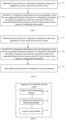
- the step 11 can include step 1111 - step 1113.
- an effective time duration of the historical scheduling information is obtained.
- the effective time duration may also be referred as the valid time length.
- the base station can notify the UE of an effective time duration of scheduling information, such as 30 minutes while sending the scheduling information to the UE at a historical time instant. Alternatively, after the time instant, the UE is notified of the effective time duration of the scheduling information through a separate signaling.
- an effective time duration of scheduling information such as 30 minutes while sending the scheduling information to the UE at a historical time instant.
- the UE is notified of the effective time duration of the scheduling information through a separate signaling.
- an interval duration between the current time and a receiving time of the historical scheduling information is determined.
- the target type carrier is determined according to the uplink carrier grant information in the historical scheduling information.
- the interval duration ⁇ T is compared with the valid time length of the historical scheduling information, and it is still assumed that the effective time duration of the historical scheduling information is 30 minutes. If ⁇ T is shorter than 30 minutes, the UE can determine the target type carrier base on the uplink carrier grant information in the historical scheduling information. For example, if the uplink carrier granted in the most recent historical scheduling information belongs to a non-SUL carrier, the target type carrier is currently determined to be a non-SUL carrier; if the uplink carrier granted in the most recent historical scheduling information belongs to a SUL carrier, then the target type carrier is currently determined to be a SUL carrier.
- ⁇ T is greater than or equal to 30 minutes, it is considered that the UE has not received the scheduling grant for a long time. During this time period, the channel conditions can have changed significantly, and the uplink grant information in the historical scheduling information may become useless. At this time, the UE can determine the target carrier type according to a first implementation described above, so as to ensure the accuracy of the selection for the target uplink carrier.
- target AC configuration information applicable to the target type carrier is determined according to the access control AC configuration information issued by the base station.
- the UE when the UE initiates a traffic request, it needs to determine whether the UE is currently allowed to access the network based on the AC (Access Control) configuration information issued by the base station. That is, the AC process is performed.
- the AC configuration information is used to inform the UE under which conditions it will be restricted from accessing the network, or under which conditions it will be allowed to access the network.
- the base station needs to inform the UE of two types of AC configuration information including: the first AC configuration information applicable to a non-SUL carrier and the second AC configuration information applicable to a SUL carrier.
- the UE further determines the target AC configuration information applicable to itself, so as to perform the AC process according to the target AC configuration information.
- the current UE can use at least one of the following implementations to determine the target AC configuration information applicable to itself. Taking the current UE1 selecting a SUL carrier as an example, the implementations will be described below.
- the base station issues independent sets of AC configuration information for non-SUL carriers and SUL carriers.
- the UE can receive two sets of AC configuration information sent by the base station.
- the UE can store the above two sets of AC configuration information in the form of a list, as shown in Table 1: Table 1 Uplink Carrier Type AC Configuration Information Non-SUL Carrier First AC Configuration Information SUL Carrier Second AC Configuration Information
- Each set of AC configuration information can include: a correspondence between access detection parameters and AC barring configuration information.
- the access detection parameter is a parameter that is to be detected when determining whether the UE can access a cell network according to a preset access control mechanism, such as PLMN (Public Land Mobile Network) identification, Access Category, Access Identity of a UE and other parameters.
- PLMN Public Land Mobile Network
- the access barring configuration information can be a limit value set based on one or more of the above access detection parameters, and the limit value can be a specific value, a range of values, etc., which is not limited in the present disclosure.
- UE1 can match the table 1 according to the target type carrier, for example, the SUL carrier, and determine the second AC configuration information as the target AC configuration information.
- the target type carrier for example, the SUL carrier
- the base station issues a set of public AC configuration information to the UE while issuing carrier applicable information.
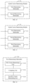
- the step 12 can include step 121 - step 122.
- step 121 public AC configuration information and carrier applicable information issued by the base station are obtained.
- the UE can obtain a set of public AC configuration parameters from the system message issued by the base station, and receive carrier applicable information issued by the base station.
- the carrier applicable information is used to indicate an uplink carrier applicable condition of each piece of sub-configuration information included in the public AC configuration information.
- target AC configuration information applicable to the target type carrier is determined by matching the carrier applicable information of each piece of sub-configuration information against the target type carrier.
- the carrier applicable information issued by the base station can be empty.
- the UE can determine that the above public AC configuration information is applicable to both SUL carriers and non-SUL carriers according to a preset rule.
- the above public AC configuration information is only applicable to non-SUL carriers.
- the carrier applicable information issued by the base station is not empty.
- the implementation of the above step 122 can include the following two cases.
- the carrier applicable information includes applicable carrier types.
- the applicable carrier types are used to explicitly indicate the uplink carrier types to which the pieces of sub-configuration information included in the public AC configuration information respectively apply.
- the UE can determine target AC configuration information by matching the carrier type information respectively applicable to the each piece of sub-configuration information against the target type carrier selected by the UE.
- the public AC configuration information mentioned above is divided into N parts according to a preset rule. That is, the public AC configuration information includes a total of N pieces of sub-configuration information, respectively represented as: configuration information 1, configuration information 2, configuration information 3, ... , configuration information N.
- the base station can indicate which type of uplink carrier each piece of sub-configuration information is applicable to with the carrier applicable information.
- the UE can use the following Table 2 to record the information issued by the base station: Table 2 Public AC Configuration Information Applicable Carrier Type Configuration Information 1 Non-SUL Carrier Configuration Information 2 SUL Carrier Configuration Information 3 Both Applicable ...... .... Configuration Information N SUL Carrier Table 2 records the correspondence between pieces of sub-configuration information and the applicable carrier types.
- One piece of sub-configuration information can be applicable to one type of uplink carrier, and can also be applicable to both two types of uplink carriers, such as the configuration information 3 above.
- the process for UE1 to determine the target AC configuration information is as follows.
- the target type carrier for example, the SUL carrier
- items in Table 2 are matched with the SUL carrier to determine the target AC configuration information, including: configuration information 2, configuration information 3...configuration information N.
- the carrier applicable information also includes an effective time range.
- the effective time range indicates an allowable time range in which a piece of sub-configuration information is applicable to the preset uplink carrier.
- the effective time range may also be referred as the valid time range.
- the step 122 can include step 1221 - step 1223.
- the applicable carrier type of each piece of sub-configuration information is matched against the target type carrier.
- step 1222 if the target type carrier belongs to the applicable carrier type of the sub-configuration information, whether the current time is within the effective time range is determined.
- step 1223 if the current time is within the effective time range, it is determined that the sub-configuration information belongs to the target AC configuration information.
- the UE can use a preset list to record the correspondence between the pieces of sub-configuration information in the public AC configuration information, and the applicable carrier types and the effective time ranges, as shown in Table 3: Table 3 Public AC Configuration Information Applicable Carrier Type Effective Time Range Configuration Information 1 Non-SUL Carrier None Configuration Information 2 SUL Carrier First Time Range Configuration Information 3 Both Applicable None ?? .... .... Configuration Information N SUL Carrier Second Time Range
- the value of the "effective time range" field being None means that there is no limit for the valid time.
- the process for UE1 to determine the target AC configuration information is as follows.
- the target type carrier for example, the SUL carrier
- items in Table 3 are matched with the SUL carrier to determine the target AC configuration information, including: configuration information 2, configuration information 3... configuration information N.
- the determination for the time validity is continued.
- the UE1 continues to determine whether the current time is within the first time range; if so, it is determined that the configuration information 2 belongs to the target AC configuration information. On the contrary, if the current time is outside the first time range, it is determined that the configuration information 2 does not belong to the target AC configuration information of the UE1. In the same way, determination for other pieces of sub-configuration information that is applicable to the SUL carrier and set with an effective time range is performed through the above process, and all pieces of sub-configuration information that meets the carrier applicable conditions are determined as the target AC configuration information of UE1.
- the target AC configuration information is matched against the access detection information of the user equipment, to determine whether the user equipment is allowed to perform the AC process through the target type carrier.
- AC barring decision can be performed by matching the access detection information of the UE against the target AC configuration information.
- the access detection information of the UE is the information that needs to be detected when determining whether the UE can access the cell network through the target type carrier according to the preset access control mechanism.
- the access detection information can include: PLMN id, Access Category, Access identity, traffic type and other parameter value.
- the target AC configuration information includes: AC barring configuration information corresponding to an access detection parameter.
- the AC barring configuration information can be a limit value set for one or more of the aforementioned access detection parameters.
- the AC barring configuration information of configuration information 2 is: (PLMN ID, 6)
- PLMN ID 6
- the process for UE1 to perform AC barring decision is: when UE1 determines to access the network through a SUL carrier, it first matches the above-mentioned target AC configuration information, namely configuration information 2, against its own PLMN ID. If the PLMN ID of UE1 is 6, UE1 is restricted from accessing to the network. On the contrary, if the PLMN ID of UE1 is not 6, it is determined that UE1 can initiate a network access request through the SUL carrier, that is, an RA request or a traffic request.
- the AC configuration information can include: AC barring configuration information corresponding to various access detection parameters, for example, as shown in Table 4: Table 4 PLMN ID Access categories Access identities 6 0 ⁇ 5 1, 3, 10
- the UE1 performs the AC barring decision process as follows. First, the target AC configuration information is matched against its own PLMN ID. If the PLMN ID of UE1 is 6, it can be further determined whether its access category is in the range of 0 ⁇ 5. If so, it can be further determined whether its access identity is any one of 1, 3, and 10. If so, it can be determined that UE1 is prohibited from accessing the network through the SUL carrier. On the contrary, if the access detection information of UE1 cannot satisfy all the above three restricted access conditions, it is determined that UE1 can access the network through the SUL carrier.
- the situation where the UE is restricted from accessing the network through the target type carrier can include two types: allowed access and restricted access with delay.
- the access detection information of UE1 satisfies the three access restriction conditions in Table 4, it is necessary to further determine whether the access restriction configuration parameters include: a barring factor and barring time. If the access restriction configuration parameter does not include the restriction factor, it is determined that the user equipment is allowed to access the network through the SUL carrier.
- the access restriction configuration parameter includes the restriction factor
- a random number "rand” is randomly generated, “rand” is compared with the restriction factor; if the random number "rand” is less than the restriction factor, it is determined that UE1 is allowed to access the network through the SUL carrier; if the random number "rand” is greater than or equal to the restriction factor, it is determined that the user equipment is allowed to access the network after a delay according to the barring time.
- the sub-configuration information applicable to the SUL carrier also includes, according to related access control mechanisms, a barring factor and corresponding barring time, for example, as shown in Table 5: Table 5 PLMN ID Access categories Access identities barring factor barring time 6 0 ⁇ 5 1, 3, 10 0.6 5s
- Table 5 also includes a barring factor. If the value of this field is 0, it means that UE1 is permanently restricted from accessing the network through the SUL carrier. If the value of the barring factor field is not 0, for example, it is 0.6 in Table 5, UE1 will randomly generate a random number "rand" between [0, 1) and compare it with the restriction factor 0.6.
- the random number is less than 0.6, it is determined that UE1 is allowed to access the network through the SUL carrier; on the contrary, if the random number is greater than or equal to 0.6, it is determined that UE1 is restricted to access with a delay, and a timer is started at the same time.
- how to perform the AC process is not limited to the above example, and can refer to the access control mechanism in the related technology, which will not be elaborated herein.
- the UE can use two types of uplink carriers, namely the non-SUL carrier and the SUL carrier, to initiate a random access request or a traffic request to the network to improve the uplink coverage performance of the 5G NR system, and improve the user experience of the 5G NR system.
- the UE can also perform the AC process based on the second AC configuration information that is applicable to the SUL carrier issued by the base station, to prevent the UE from blindly initiating an RA request or a traffic request to the base station through the SUL carrier and causing congestion in the channel of the SUL carrier.
- the AC process can also be performed to prevent the UE from initiating a traffic request through the non-SUL carrier when the non-SUL carrier channel load of the network is too high, thus improving the accuracy of load control on the uplink carrier and ensuring the reliability of information transmission on the non-SUL carrier.
- the present disclosure also provides a method for controlling network access on the base station side.
- a method for controlling network access on the base station side can include the following steps.
- access control AC configuration information respectively applicable to a SUL carrier and a non-SUL carrier are determined.
- the base station can determine the AC configuration information applicable to the SUL carrier according to information such as the load condition of the SUL carrier of a cell.
- the AC configuration information applicable to the non-SUL carrier can be referred to as the first AC configuration information
- the configuration information applicable to the SUL carrier can be referred to as the second AC configuration information.
- the AC configuration information is sent to the user equipment, so that the user equipment determines the target AC configuration information according to the target type carrier for carrying the traffic to be transmitted and performs an access control AC process based on the target AC configuration information.
- the base station can use the following at least two implementations to set AC configuration information for the two types of uplink carriers.
- the base station generates two independently configured AC configuration lists according to the first AC configuration information and the second AC configuration information and the applicable uplink carriers.
- the two independently configured AC configuration lists include the first AC configuration list and the second AC configuration list.
- Each AC configuration list includes a correspondence between a preset uplink carrier and the AC configuration information.
- the base station can send the first AC configuration list and the second AC configuration list to the UE respectively through two messages.
- the base station sends the two AC configuration lists to the UE simultaneously through a message.
- the UE receives the two AC configuration lists configured independently of each other.
- the UE can match the two AC configuration lists with the target type carrier to quickly determine the target AC configuration information applicable to the target type carrier, thereby improving the efficiency of performing the AC process.
- the base station provides a set of public AC configuration information for the two types of uplink carriers according to the first AC configuration information and the second AC configuration information and determines applicable ranges for the carriers, that is, determines the carrier applicable information of each piece of the sub-configuration information in the public AC configuration information.
- the carrier applicable information is used to indicate an uplink carrier applicable condition of each piece of sub-configuration information in the public AC configuration information, and the carrier applicable information includes at least an applicable carrier type.
- the above carrier applicable information can further include: an effective time range indicating an allowable time range in which the sub-configuration information is applicable to a preset uplink carrier.
- the base station can send the public AC configuration information and carrier applicable information to the UE at the same time through one message, thus saving system signaling overhead.
- the present disclosure also provides examples of apparatuses and corresponding terminals for implementing application functions.
- the present disclosure provides an apparatus for controlling network access, which can be provided in user equipment.
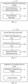
- an apparatus for controlling network access which can be provided in user equipment. Referring to a block diagram of an apparatus for controlling network access according to an example shown in FIG. 9 , and the apparatus can include:
- the uplink carrier determining module 31 can include:
- the uplink carrier determining module 31 can include any one of the following submodules:
- the first determining submodule 311 can include:
- the third determining submodule 313 can include:
- the configuration information determining module 32 can include:
- the configuration information determining module 32 can include:
- the configuration information determining module 32 can include:
- the carrier applicable information can further include: an effective time range indicating an allowable time range in which the sub-configuration information is applicable to a preset uplink carrier.
- the sending module 42 can include:
- the sending module can include: an information setting submodule 423 configured to provide public AC configuration information and carrier applicable information according to the first AC configuration information and the second AC configuration information, where the carrier applicable information is configured to indicate an uplink carrier applicable condition of each piece of sub-configuration information in the public AC configuration information, and the carrier applicable information includes at least an applicable carrier type.
- the carrier applicable information further includes: an effective time range indicating an allowable time range in which the sub-configuration information is applicable to a preset uplink carrier.
- a second sending submodule 424 is configured to send the public AC configuration information and the carrier applicable information to the user equipment, to enable the user equipment to respectively determine first AC configuration information applicable to the non-SUL carrier and second AC configuration information applicable to the SUL carrier based on the public AC configuration information and the carrier applicable information.
- the apparatus can further include: an indication information sending module 43 configured to send uplink carrier indication information to the user equipment, where the uplink carrier indication information is configured to inform the user equipment to initiate a network access request through a specified type of uplink carrier, where the specified type of uplink carrier is a SUL carrier or a non-SUL carrier.
- an indication information sending module 43 configured to send uplink carrier indication information to the user equipment, where the uplink carrier indication information is configured to inform the user equipment to initiate a network access request through a specified type of uplink carrier, where the specified type of uplink carrier is a SUL carrier or a non-SUL carrier.
- the apparatus example since it basically corresponds to the method example, reference can be made to the relevant part of the description of the method example.
- the apparatus examples described above are merely illustrative, and the units described above as separate components can or cannot be physically separated, and the components displayed as units can or cannot be physical units. That is, they can be located in one location, or it can be distributed to multiple network units. Some or all of the modules can be selected according to actual needs to achieve the objectives of the solutions of the present disclosure. Those of ordinary skill in the art can understand and implement it without creative work.
- an apparatus for controlling network access including: a processor; and a memory for storing executable instructions of the processor; wherein the processor is configured to:
- Another aspect provides an apparatus for controlling network access, including: a processor; and a memory for storing executable instructions of the processor; wherein the processor is configured to:
- FIG. 22 is a block diagram illustrating an apparatus 2200 for controlling network access according to an example.
- the apparatus 2200 can be user equipment such as a mobile phone, a computer, a digital broadcasting terminal, a messaging device, a game console, a tablet device, a medical device, fitness equipment, a personal digital assistant, or a wearable device such as a smart watch, smart glasses, a smart wristband, smart sneakers, or the like.
- the apparatus 2200 can include one or more of the following components: a processing component 2202, a memory 2204, a power supply component 2206, a multimedia component 2208, an audio component 2210, an input/output (I/O) interface 2212, a sensor component 2214, and a communication component 2216.
- the processing component 2202 generally controls overall operations of the apparatus 2200, such as operations associated with display, phone calls, data communications, camera operations, and recording operations.
- the processing component 2202 can include one or more processors 2220 to execute instructions to complete all or part of the steps of the above methods.
- the processing component 2202 can include one or more modules which facilitate the interaction between the processing component 2202 and other components.
- the processing component 2202 can include a multimedia module to facilitate the interaction between the multimedia component 2208 and the processing component 2202.
- the power supply component 2206 supplies power for different components of the apparatus 2200.
- the power supply component 2206 can include a power supply management system, one or more power supplies, and other components associated with generating, managing and distributing power for the apparatus 2200.
- the multimedia component 2208 includes a screen providing an output interface between the apparatus 2200 and a user.
- the screen can include a Liquid Crystal Display (LCD) and a Touch Panel (TP). If the screen includes the TP, the screen can be implemented as a touch screen to receive input signals from the user.
- the TP can include one or more touch sensors to sense touches, swipes, and gestures on the TP.
- the touch sensors can not only sense a boundary of a touch or swipe, but also sense a duration and a pressure associated with the touch or swipe.
- the multimedia component 2208 can include a front camera and/or a rear camera.
- the front camera and/or rear camera can receive external multimedia data when the apparatus 2200 is in an operating mode, such as a photographing mode or a video mode.
- an operating mode such as a photographing mode or a video mode.
- Each of the front camera and the rear camera can be a fixed optical lens system or have focal length and optical zooming capability.
- the audio component 2210 is configured to output and/or input an audio signal.
- the audio component 2210 includes a microphone (MIC).
- the microphone is configured to receive an external audio signal.
- the received audio signal can be further stored in the memory 2204 or sent via the communication component 2216.
- the audio component 2210 further includes a speaker for outputting an audio signal.
- the I/O interface 2212 provides an interface between the processing component 2202 and a peripheral interface module.
- the above peripheral interface module can be a keyboard, a click wheel, buttons, or the like. These buttons can include but not limited to, a home button, a volume button, a start button and a lock button.
- the sensor component 2214 includes one or more sensors to provide status assessments of various aspects for the apparatus 2200.
- the sensor component 2214 can detect the on/off status of the apparatus 2200, and relative positioning of component, for example, the component is a display and a keypad of the apparatus 2200.
- the sensor component 2214 can also detect a change in position of the apparatus 2200 or a component of the apparatus 2200, a presence or absence of the contact between a user and the apparatus 2200, an orientation or an acceleration/deceleration of the apparatus 2200, and a change in temperature of the apparatus 2200.
- the sensor component 2214 can include a proximity sensor configured to detect the presence of a nearby object without any physical contact.
- the sensor component 2214 can further include an optical sensor, such as a Complementary Metal-Oxide-Semiconductor (CMOS) or Charged Coupled Device (CCD) image sensor which is used in imaging applications.
- CMOS Complementary Metal-Oxide-Semiconductor
- CCD Charged Coupled Device
- the sensor component 2214 can further include an acceleration sensor, a gyroscope sensor, a magnetic sensor, a pressure sensor, or a temperature sensor.
- the communication component 2216 is configured to facilitate wired or wireless communication between the apparatus 2200 and other devices.
- the apparatus 2200 can access a wireless network based on a communication standard, such as Wi-Fi, 2G or 3G, or a combination thereof.
- the communication component 2216 receives a broadcast signal or broadcast related information from an external broadcast management system via a broadcast channel.
- the communication component 2216 can further include a Near Field Communication (NFC) module for promoting short-range communication.
- the NFC module can be implemented based on a radio frequency identification (RFID) technology, an infrared data association (IrDA) technology, an ultra-wideband (UWB) technology, a Bluetooth ® (BT) technology and other technologies.
- RFID radio frequency identification
- IrDA infrared data association
- UWB ultra-wideband
- BT Bluetooth ®
- the apparatus 2200 can be implemented by one or more Application Specific Integrated Circuits (ASICs), Digital Signal Processors (DSPs), Digital Signal Processing Devices (DSPDs), programmable Logic Devices (PLDs), Field Programmable Gate Arrays (FPGAs), controllers, microcontrollers, microprocessors, or other electronic components for performing the above methods.
- ASICs Application Specific Integrated Circuits
- DSPs Digital Signal Processors
- DSPDs Digital Signal Processing Devices
- PLDs programmable Logic Devices
- FPGAs Field Programmable Gate Arrays
- controllers microcontrollers, microprocessors, or other electronic components for performing the above methods.
- a non-transitory computer readable storage medium including instructions is further provided, such as the memory 2204 including instructions.
- the above instructions can be executed by the processor 2220 of the apparatus 2200 to complete the method for controlling network access illustrated in any of FIG. 2 - FIG. 6 .
- the non-transitory computer readable storage medium can be a Read-Only Memory (ROM), a Random Access Memory (RAM), a CD-ROM, a magnetic tape, a floppy disk, an optical data storage device, and so on.
- FIG. 23 is a block diagram illustrating an apparatus 2300 for controlling network access according to an exemplary embodiment.
- the apparatus 2300 can be a base station.
- the apparatus 2300 includes a processing component 2322, a wireless transmission / reception component 2324, an antenna component 2326, and a signal processing part unique to the wireless interface.
- the processing component 2322 may further include one or more processors.
- One processor of the processing component 2322 can be configured to:
- a non-transitory computer-readable storage medium including instructions is provided, the instructions can be executed by one processor of the processing component 2322 to complete the method for controlling network access illustrated in any of FIG. 7 - FIG. 9 .
- the non-transitory computer-readable storage medium can be a ROM, a random access memory (RAM), a CD-ROM, a magnetic tape, a floppy disk, an optical data storage device, or the like.
Landscapes
- Engineering & Computer Science (AREA)
- Signal Processing (AREA)
- Computer Networks & Wireless Communication (AREA)
- Quality & Reliability (AREA)
- Physics & Mathematics (AREA)
- Electromagnetism (AREA)
- Computer Security & Cryptography (AREA)
- Mobile Radio Communication Systems (AREA)
Claims (8)
- Verfahren zur Steuerung eines Netzwerkzugriffs, anwendbar auf ein Nutzergerät, dadurch gekennzeichnet, dass es Folgendes umfasst:Ermitteln (11) eines Zielträgertyps, der zu übertragenden Verkehr transportiert, wenn eine Verkehrsanforderung initiiert werden soll, wobei der Zielträgertyp Folgendes umfasst: einen Ergänzungs-Uplink-Träger, kurz SUL-Träger, oder einen Nicht-SUL-Träger;Ermitteln (12) einer Zielzugriffssteuerungs-, Ziel-AC-, Konfigurationsinformation, die auf den Zielträgertyp anwendbar ist, gemäß einer von einer Basisstation ausgegebenen Ziel-AC-Konfigurationsinformation; undErmitteln (13), ob das Nutzergerät einen AC-Prozess über den Ziel-Uplink-Träger ausführen darf, indem die Ziel-AC-Konfigurationsinformation mit Zugriffserkennungsinformationen des Nutzergeräts abgeglichen wird;wobei das Ermitteln der Ziel-AC-Konfigurationsinformation, die auf den Zielträgertyp anwendbar ist, gemäß der von der Basisstation ausgegebenen Ziel-AC-Konfigurationsinformation Folgendes umfasst:Beschaffen (121) einer öffentlichen AC Konfigurationsinformation und einer Träger-anwendbaren Information, die von der Basisstation ausgegeben werden, wobei die Träger-anwendbare Information eine Uplink-Träger-Anwendbarkeitsbedingung jeder Teil-Konfigurationsinformation in der öffentlichen AC Konfigurationsinformation angibt und die Träger-anwendbare Information zumindest einen anwendbaren Trägertyp umfasst; undErmitteln (122) der Ziel-AC Konfigurationsinformation, die auf den Zielträgertyp anwendbar ist, durch Abgleichen der Träger-anwendbaren Information jeder Teil-Konfigurationsinformation mit dem Zielträgertyp;wobei die Träger-anwendbare Information ferner umfasst: einen effektiven Zeitbereich, der einen zulässigen Zeitbereich angibt, in dem die Teil-Konfigurationsinformation auf einen voreingestellten Uplink-Träger anwendbar ist; unddas Ermitteln der Ziel-AC-Konfigurationsinformation, die auf den Zielträgertyp anwendbar ist, durch Abgleichen der Träger-anwendbaren Information jeder Teil-Konfigurationsinformation mit dem Zielträgertyp umfasst:Abgleichen (1221) des anwendbaren Trägertyps jeder Teil-Konfigurationsinformation mit dem Zielträgertyp;Ermitteln (1222), ob eine aktuelle Zeit innerhalb des effektiven Zeitbereichs liegt, wenn der Zielträgertyp zu dem anwendbaren Trägertyp einer Teil-Konfigurationsinformation gehört; undErmitteln (1223), dass die Teil-Konfigurationsinformation zu der Ziel-AC-Konfigurationsinformation gehört, wenn die aktuelle Zeit innerhalb des effektiven Zeitbereichs liegt.
- Verfahren nach Anspruch 1, wobei als Reaktion darauf, dass sich das Nutzergerät derzeit in einem der folgenden Zustände befindet: in einem inaktiven Zustand, einem Ruhezustand oder einem nicht synchronisierten Zustand in einem verbundenen Zustand, Ermitteln des Zielträgertyps, der zu übertragenden Verkehr transportiert, umfassend:Ermitteln des Zielträgertyps gemäß einer empfangenen Referenzsignalleistung, RSRP; oderErmitteln des Zieltyp-Trägers gemäß einer von der Basisstation ausgegebenen Uplink-Träger-Hinweisinformation, wobei die Uplink-Träger-Hinweisinformation das Nutzergerät dahingehend informiert, eine Zufallszugriffsanforderung über einen spezifizierten Typ eines Uplink-Trägers zu initiieren.
- Verfahren nach Anspruch 1 oder 2, wobei als Reaktion darauf, dass sich das Nutzergerät gegenwärtig in einem verbundenen Zustand befindet, der Zielträgertyp durch Ausführen zumindest einer der folgenden Handlungen ermittelt wird:Ermitteln des Zielträgertyps gemäß neuester historischer Planungsinformationen, die Uplink-Träger-Zuteilungsinformationen umfassen;Ermitteln des Zielträgertyps gemäß einer empfangenen Referenzsignalleistung, RSRP; oderErmitteln des Zielträgertyps gemäß von der Basisstation ausgegebener Uplink-Träger-Hinweisinformationen, wobei die Uplink-Träger-Hinweisinformationen das Nutzergerät dahingehend informieren, eine Verkehrsanforderung über einen spezifizierten Uplink-Trägertyp zu initiieren.
- Verfahren nach Anspruch 2 oder 3, wobei das Ermitteln des Zielträgertyps gemäß dem RSRP umfasst:Vergleichen (1101) eines detektierten RSRP mit einem voreingestellten Leistungsschwellenwert;Ermitteln (1102) des SUL-Trägers als Zielträgertyp, wenn der RSRP kleiner als der voreingestellte Leistungsschwellenwert ist; undErmitteln (1103) des Nicht-SUL-Trägers als Zielträgertyp, wenn der RSRP größer oder gleich dem voreingestellten Leistungsschwellenwert ist.
- Verfahren nach Anspruch 3, wobei das Ermitteln des Zielträgertyps gemäß den neuesten historischen Planungsinformationen umfasst:Beschaffen (1111) einer effektiven Zeitdauer der historischen Planungsinformationen;Ermitteln (1112) einer Intervalldauer zwischen einem aktuellen Zeitpunkt und einem Empfangszeitpunkt der historischen Planungsinformationen; undErmitteln (1113) des Zielträgertyps gemäß den Uplink-Trägerzuteilungsinformationen in den historischen Planungsinformationen als Reaktion darauf, dass die Intervalldauer kürzer als die effektive Zeitdauer ist.
- Verfahren zum Steuern eines Netzwerkzugriffs, anwendbar auf eine Basisstation, dadurch gekennzeichnet, dass es umfasst:Ermitteln (21) einer Zugriffssteuerungs-, AC-, Konfigurationsinformation, die auf einen Ergänzungs-Uplink, oder SUL, -Träger und einen Nicht-SUL-Träger anwendbar ist, wobei die AC Konfigurationsinformation eine erste AC Konfigurationsinformation, die auf den Nicht-SUL-Träger anwendbar ist, und eine zweite AC Konfigurationsinformation, die auf den SUL-Träger anwendbar ist, umfasst; undSenden (22) der AC Konfigurationsinformation an ein Nutzergerät, um dem Nutzergerät zu ermöglichen, eine Ziel-AC-Konfigurationsinformation gemäß einem Zielträgertyp zum Transportieren von zu übertragendem Verkehr zu ermitteln und einen AC-Prozess basierend auf der Ziel-AC-Konfigurationsinformation durchzuführen;wobei das Senden der AC Konfigurationsinformation an das Nutzergerät umfasst:Bereitstellen einer öffentlichen AC Konfigurationsinformation und einer Träger-anwendbaren Information gemäß der ersten AC Konfigurationsinformation und der zweiten AC Konfigurationsinformation, wobei die Träger-anwendbare Information eine anwendbare Uplink-Trägerbedingung jeder Teil-Konfigurationsinformation in der öffentlichen AC Konfigurationsinformation angibt und die Träger-anwendbare Information zumindest einen anwendbaren Trägertyp umfasst; undSenden der öffentlichen AC Konfigurationsinformation und der Träger-anwendbaren Information an das Nutzergerät, um dem Nutzergerät zu ermöglichen, basierend auf der öffentlichen AC Konfigurationsinformation und der Träger-anwendbaren Information jeweils eine erste AC Konfigurationsinformation, die auf den Nicht-SUL-Träger anwendbar ist, und eine zweite AC Konfigurationsinformation, die auf den SUL-Träger anwendbar ist, zu ermitteln;wobei die Träger-anwendbare Information ferner umfasst: einen effektiven Zeitbereich, der einen zulässigen Zeitbereich angibt, in dem die Teil-Konfigurationsinformation auf einen voreingestellten Uplink-Träger anwendbar ist.
- Verfahren nach Anspruch 6, ferner umfassend:
Senden (23) von Uplink-Träger-Hinweisinformationen an das Nutzergerät, wobei die Uplink-Träger-Hinweisinformationen das Nutzergerät dahingehend informieren, eine Netzzugriffsanforderung über einen spezifizierten Typ eines Uplink-Trägers zu initiieren, wobei der spezifizierte Typ eines Uplink-Trägers ein SUL-Träger oder ein Nicht-SUL-Träger ist. - Apparat zur Steuerung eines Netzwerkzugriffs, dadurch gekennzeichnet, dass er Folgendes umfasst:einen Prozessor (2220); undeinen Speicher (2204) zum Speichern von durch den Prozessor ausführbaren Anweisungen;wobei der Prozessor dazu konfiguriert ist:einen Zielträgertyp zu ermitteln (11), der zu übertragenden Verkehr transportiert, wenn eine Verkehrsanforderung initiiert werden soll, wobei der Zielträgertyp Folgendes umfasst: einen Ergänzungs-Uplink-SUL-Träger oder einen Nicht-SUL-Träger;Ermitteln (12) einer Zielzugriffssteuerung bzw. Ziel-AC Konfigurationsinformation, die auf den Zielträgertyp anwendbar ist, gemäß einer von einer Basisstation ausgegebenen AC Konfigurationsinformation; undErmitteln (13), ob das Nutzergerät einen AC-Prozess über den Ziel-Uplink-Träger ausführen darf, indem die Ziel-AC-Konfigurationsinformation mit Zugriffserkennungsinformationen des Nutzergeräts abgeglichen wird;wobei das Ermitteln der Ziel-AC-Konfigurationsinformation, die auf den Zielträgertyp anwendbar ist, gemäß der von der Basisstation ausgegebenen AC Konfigurationsinformation Folgendes umfasst:Beschaffen (121) einer öffentlichen AC Konfigurationsinformation und einer Träger-anwendbaren Information, die von der Basisstation ausgegeben werden, wobei die Träger-anwendbare Information eine Uplink-Träger-Anwendbarkeitsbedingung jeder Teil-Konfigurationsinformation in der öffentlichen AC Konfigurationsinformation angibt und die Träger-anwendbare Information zumindest einen anwendbaren Trägertyp umfasst; undErmitteln (122) der Ziel-AC Konfigurationsinformation, die auf den Zielträgertyp anwendbar ist, durch Abgleichen der Träger-anwendbaren Information jeder Teil-Konfigurationsinformation mit dem Zielträgertyp;wobei die Träger-anwendbare Information ferner umfasst: einen effektiven Zeitbereich, der einen zulässigen Zeitbereich angibt, in dem die Teil-Konfigurationsinformation auf einen voreingestellten Uplink-Träger anwendbar ist; undwobei das Ermitteln der Ziel-AC-Konfigurationsinformation, die auf den Zielträgertyp anwendbar ist, durch Abgleichen der Träger-anwendbaren Information jeder Teil-Konfigurationsinformation mit dem Zielträgertyp umfasst:Abgleichen (1221) des anwendbaren Trägertyps jeder Teil-Konfigurationsinformation mit dem Zielträgertyp;Ermitteln (1222), ob ein aktueller Zeitpunkt innerhalb des effektiven Zeitbereichs liegt, wenn der Zielträgertyp zum anwendbaren Trägertyp einer Teil-Konfigurationsinformation gehört; undErmitteln (1223), dass die Teil-Konfigurationsinformation zur Ziel-AC-Konfigurationsinformation gehört, wenn der aktuelle Zeitpunkt innerhalb des effektiven Zeitbereichs liegt.
Applications Claiming Priority (1)
| Application Number | Priority Date | Filing Date | Title |
|---|---|---|---|
| PCT/CN2018/083786 WO2019200591A1 (zh) | 2018-04-19 | 2018-04-19 | 控制网络接入的方法及装置 |
Publications (3)
| Publication Number | Publication Date |
|---|---|
| EP3783959A1 EP3783959A1 (de) | 2021-02-24 |
| EP3783959A4 EP3783959A4 (de) | 2021-05-05 |
| EP3783959B1 true EP3783959B1 (de) | 2025-06-25 |
Family
ID=63428686
Family Applications (1)
| Application Number | Title | Priority Date | Filing Date |
|---|---|---|---|
| EP18915324.0A Active EP3783959B1 (de) | 2018-04-19 | 2018-04-19 | Verfahren und vorrichtung zur steuerung von netzwerkzugang |
Country Status (4)
| Country | Link |
|---|---|
| US (1) | US11503534B2 (de) |
| EP (1) | EP3783959B1 (de) |
| CN (1) | CN108521883B (de) |
| WO (1) | WO2019200591A1 (de) |
Families Citing this family (18)
| Publication number | Priority date | Publication date | Assignee | Title |
|---|---|---|---|---|
| KR102751886B1 (ko) * | 2018-08-03 | 2025-01-09 | 삼성전자주식회사 | 무선 통신 시스템에서 데이터를 송수신하기 위한 방법 및 장치 |
| WO2020062860A1 (en) * | 2018-09-26 | 2020-04-02 | Huawei Technologies Co., Ltd. | System and method for communications using supplementary uplink |
| CN111083725A (zh) * | 2018-10-22 | 2020-04-28 | 中国移动通信集团设计院有限公司 | Sul模式下上行频段转换方法和装置 |
| CN111225410B (zh) * | 2018-11-24 | 2022-05-10 | 华为技术有限公司 | 一种确定上行链路的方法及装置 |
| CN111294931B (zh) * | 2018-12-10 | 2022-09-16 | 华为技术有限公司 | 一种通信方法、装置及计算机可读存储介质 |
| CN111356245B (zh) * | 2018-12-24 | 2022-07-29 | 成都鼎桥通信技术有限公司 | 非对称上行载波聚合的初始接入方法和系统 |
| CN111385887B (zh) * | 2018-12-29 | 2023-05-09 | 中兴通讯股份有限公司 | 传输数据的方法、装置、设备和存储介质 |
| CN111278142A (zh) * | 2019-01-25 | 2020-06-12 | 维沃移动通信有限公司 | 一种随机接入方法及终端 |
| CN112997556B (zh) * | 2019-02-15 | 2023-06-27 | Oppo广东移动通信有限公司 | 传输信号的方法及设备 |
| CN110267346B (zh) * | 2019-04-29 | 2021-10-26 | 华为技术有限公司 | 一种通信方法、装置及存储介质 |
| CN110337140B (zh) * | 2019-05-31 | 2021-06-01 | 华为技术有限公司 | 一种通信方法及装置 |
| CN110475304B (zh) * | 2019-07-09 | 2021-10-26 | 华为技术有限公司 | 一种无线资源控制连接方法及装置 |
| WO2021022397A1 (zh) * | 2019-08-02 | 2021-02-11 | Oppo广东移动通信有限公司 | 功率控制方法、装置、计算机设备和存储介质 |
| EP4075912A4 (de) * | 2019-12-10 | 2022-11-23 | Guangdong Oppo Mobile Telecommunications Corp., Ltd. | Datenübertragungsverfahren und -vorrichtung sowie speichermedium |
| WO2021208059A1 (zh) * | 2020-04-17 | 2021-10-21 | Oppo广东移动通信有限公司 | 连接建立方法、装置、设备及存储介质 |
| CN112385270B (zh) * | 2020-10-15 | 2023-10-03 | 北京小米移动软件有限公司 | 接入控制信息处理方法及装置、通信设备及存储介质 |
| CN115314929A (zh) * | 2021-05-06 | 2022-11-08 | 华为技术有限公司 | 一种用于上报小区或载波信息的方法及装置 |
| CN113992214A (zh) * | 2021-10-12 | 2022-01-28 | 维沃移动通信有限公司 | 射频控制方法、装置和电子设备 |
Family Cites Families (9)
| Publication number | Priority date | Publication date | Assignee | Title |
|---|---|---|---|---|
| EP2368398B1 (de) | 2008-11-25 | 2020-01-08 | InterDigital Patent Holdings, Inc. | Verfahren und vorrichtung zum benutzen mehrerer aufwärtsstreckenträger und mehrerer abwärtsstreckenträger |
| WO2014023999A1 (en) * | 2012-08-08 | 2014-02-13 | Nokia Siemens Networks Oy | Reactivating cells to improve positioning accuracy |
| WO2015042858A1 (zh) | 2013-09-27 | 2015-04-02 | 华为技术有限公司 | 通信的方法、用户设备和基站 |
| CN104519576A (zh) * | 2013-09-27 | 2015-04-15 | 北京三星通信技术研究有限公司 | 一种移动终端及其在无线小区中的数据传输方法 |
| CN106255212B (zh) * | 2016-07-29 | 2019-07-16 | Oppo广东移动通信有限公司 | 辅成员载波配置方法及装置、移动终端、基站、通信系统 |
| CN107734712A (zh) * | 2016-08-12 | 2018-02-23 | 电信科学技术研究院 | 一种随机接入方法和设备 |
| CN108496399B (zh) | 2016-09-20 | 2022-02-15 | 联发科技股份有限公司 | 移动通信中用于多上行链路载波数据传输的方法及其装置 |
| KR102305906B1 (ko) * | 2017-08-10 | 2021-09-28 | 삼성전자 주식회사 | 무선 통신 시스템에서 상향링크 전송 방법 및 장치 |
| WO2019137454A1 (en) * | 2018-01-11 | 2019-07-18 | Fg Innovation Ip Company Limited | Uplink carrier configuration and selection with supplementary uplink |
-
2018
- 2018-04-19 WO PCT/CN2018/083786 patent/WO2019200591A1/zh not_active Ceased
- 2018-04-19 CN CN201880000617.XA patent/CN108521883B/zh active Active
- 2018-04-19 US US17/049,005 patent/US11503534B2/en active Active
- 2018-04-19 EP EP18915324.0A patent/EP3783959B1/de active Active
Non-Patent Citations (1)
| Title |
|---|
| NOKIA ET AL: "Access attempt categorization and barring check", vol. RAN WG2, no. Vancouver, Canada; 20180122 - 20180126, 12 January 2018 (2018-01-12), XP051386548, Retrieved from the Internet <URL:http://www.3gpp.org/ftp/tsg%5Fran/WG2%5FRL2/TSGR2%5FAHs/2018%5F01%5FNR/Docs/> [retrieved on 20180112] * |
Also Published As
| Publication number | Publication date |
|---|---|
| EP3783959A1 (de) | 2021-02-24 |
| CN108521883A (zh) | 2018-09-11 |
| US11503534B2 (en) | 2022-11-15 |
| WO2019200591A1 (zh) | 2019-10-24 |
| US20210243677A1 (en) | 2021-08-05 |
| CN108521883B (zh) | 2022-12-06 |
| EP3783959A4 (de) | 2021-05-05 |
Similar Documents
| Publication | Publication Date | Title |
|---|---|---|
| EP3783959B1 (de) | Verfahren und vorrichtung zur steuerung von netzwerkzugang | |
| US20230336309A1 (en) | Non-connected-state positioning method and apparatus, and device | |
| CN111492716B (zh) | 用于随机接入的通信方法、装置及计算机可读存储介质 | |
| US12598581B2 (en) | Method for sending paging cause and method for acquiring paging cause | |
| KR102401522B1 (ko) | 업링크 전송 자원을 요청하는 방법 및 장치 | |
| CN116848933A (zh) | 信息传输方法、装置、通信设备及存储介质 | |
| JP2019517216A (ja) | システム情報伝送方法、装置、プログラム及び記録媒体 | |
| CN108521890B (zh) | 随机接入方法及装置 | |
| US12317104B2 (en) | Method and device for allocating beam failure request resources | |
| EP3541119B1 (de) | Verfahren, vorrichtung, benutzergerät und basisstation zum senden und empfangen von systeminformationen | |
| US12127260B2 (en) | Random access method and apparatus, system, and storage medium | |
| US12069654B2 (en) | Method for transmitting uplink information, apparatus base station and terminal | |
| EP4387297A1 (de) | Verfahren und vorrichtung zur durchführung kleiner datenübertragung, verfahren und vorrichtung zur bestimmung eines direktzugriffsnachrichtenübertragungsmodus, vorrichtung und speichermedium | |
| US12445942B2 (en) | Random access method and apparatus, and storage medium | |
| EP3905773B1 (de) | Verfahren und vorrichtung zur trägerkonfiguration | |
| US20250168816A1 (en) | Positioning method, positioning apparatus, and device | |
| EP4369837A1 (de) | Direktzugriffsverfahren und -vorrichtung sowie speichermedium | |
| EP3873137B1 (de) | Bestimmung, ob eine drx-periode an einem endgerät auf der grundlage einer von einer basisstation empfangenen konfigurationsänderungsantwort angepasst werden soll | |
| CN110572844B (zh) | 随机接入方法、装置及终端 | |
| US20250254750A1 (en) | Wireless transmission method and apparatus, and communication device and storage medium | |
| US11903039B2 (en) | Random access method and random access apparatus | |
| CN114651511A (zh) | 激活指示方法和装置、激活确定方法和装置 | |
| RU2832262C2 (ru) | Способ и устройство для осуществления произвольного доступа и носитель данных | |
| WO2025011537A1 (zh) | 消息发送方法、消息接收方法、装置、终端及网络侧设备 | |
| CN117678278A (zh) | 一种传输指示信息的方法、装置、设备以及可读存储介质 |
Legal Events
| Date | Code | Title | Description |
|---|---|---|---|
| STAA | Information on the status of an ep patent application or granted ep patent |
Free format text: STATUS: THE INTERNATIONAL PUBLICATION HAS BEEN MADE |
|
| PUAI | Public reference made under article 153(3) epc to a published international application that has entered the european phase |
Free format text: ORIGINAL CODE: 0009012 |
|
| STAA | Information on the status of an ep patent application or granted ep patent |
Free format text: STATUS: REQUEST FOR EXAMINATION WAS MADE |
|
| 17P | Request for examination filed |
Effective date: 20201119 |
|
| AK | Designated contracting states |
Kind code of ref document: A1 Designated state(s): AL AT BE BG CH CY CZ DE DK EE ES FI FR GB GR HR HU IE IS IT LI LT LU LV MC MK MT NL NO PL PT RO RS SE SI SK SM TR |
|
| AX | Request for extension of the european patent |
Extension state: BA ME |
|
| A4 | Supplementary search report drawn up and despatched |
Effective date: 20210401 |
|
| RIC1 | Information provided on ipc code assigned before grant |
Ipc: H04W 48/02 20090101AFI20210326BHEP Ipc: H04W 48/08 20090101ALI20210326BHEP Ipc: H04W 74/08 20090101ALI20210326BHEP Ipc: H04W 72/02 20090101ALI20210326BHEP Ipc: H04L 5/00 20060101ALI20210326BHEP Ipc: H04W 72/04 20090101ALI20210326BHEP Ipc: H04W 72/08 20090101ALI20210326BHEP |
|
| DAV | Request for validation of the european patent (deleted) | ||
| DAX | Request for extension of the european patent (deleted) | ||
| STAA | Information on the status of an ep patent application or granted ep patent |
Free format text: STATUS: EXAMINATION IS IN PROGRESS |
|
| 17Q | First examination report despatched |
Effective date: 20230313 |
|
| REG | Reference to a national code |
Ref country code: DE Free format text: PREVIOUS MAIN CLASS: H04W0048020000 Ref country code: DE Ref legal event code: R079 Ref document number: 602018083045 Country of ref document: DE Free format text: PREVIOUS MAIN CLASS: H04W0048020000 Ipc: H04W0072230000 |
|
| GRAP | Despatch of communication of intention to grant a patent |
Free format text: ORIGINAL CODE: EPIDOSNIGR1 |
|
| STAA | Information on the status of an ep patent application or granted ep patent |
Free format text: STATUS: GRANT OF PATENT IS INTENDED |
|
| RIC1 | Information provided on ipc code assigned before grant |
Ipc: H04L 5/00 20060101ALI20250221BHEP Ipc: H04W 72/02 20090101ALI20250221BHEP Ipc: H04W 74/00 20090101ALI20250221BHEP Ipc: H04W 72/23 20230101AFI20250221BHEP |
|
| INTG | Intention to grant announced |
Effective date: 20250310 |
|
| P01 | Opt-out of the competence of the unified patent court (upc) registered |
Free format text: CASE NUMBER: APP_16669/2025 Effective date: 20250407 |
|
| GRAS | Grant fee paid |
Free format text: ORIGINAL CODE: EPIDOSNIGR3 |
|
| GRAA | (expected) grant |
Free format text: ORIGINAL CODE: 0009210 |
|
| STAA | Information on the status of an ep patent application or granted ep patent |
Free format text: STATUS: THE PATENT HAS BEEN GRANTED |
|
| AK | Designated contracting states |
Kind code of ref document: B1 Designated state(s): AL AT BE BG CH CY CZ DE DK EE ES FI FR GB GR HR HU IE IS IT LI LT LU LV MC MK MT NL NO PL PT RO RS SE SI SK SM TR |
|
| REG | Reference to a national code |
Ref country code: GB Ref legal event code: FG4D |
|
| REG | Reference to a national code |
Ref country code: CH Ref legal event code: EP |
|
| REG | Reference to a national code |
Ref country code: DE Ref legal event code: R096 Ref document number: 602018083045 Country of ref document: DE |
|
| REG | Reference to a national code |
Ref country code: CH Ref legal event code: EP |
|
| REG | Reference to a national code |
Ref country code: IE Ref legal event code: FG4D |
|
| REG | Reference to a national code |
Ref country code: NL Ref legal event code: FP |
|
| PG25 | Lapsed in a contracting state [announced via postgrant information from national office to epo] |
Ref country code: FI Free format text: LAPSE BECAUSE OF FAILURE TO SUBMIT A TRANSLATION OF THE DESCRIPTION OR TO PAY THE FEE WITHIN THE PRESCRIBED TIME-LIMIT Effective date: 20250625 |
|
| REG | Reference to a national code |
Ref country code: LT Ref legal event code: MG9D |
|
| PG25 | Lapsed in a contracting state [announced via postgrant information from national office to epo] |
Ref country code: GR Free format text: LAPSE BECAUSE OF FAILURE TO SUBMIT A TRANSLATION OF THE DESCRIPTION OR TO PAY THE FEE WITHIN THE PRESCRIBED TIME-LIMIT Effective date: 20250926 Ref country code: NO Free format text: LAPSE BECAUSE OF FAILURE TO SUBMIT A TRANSLATION OF THE DESCRIPTION OR TO PAY THE FEE WITHIN THE PRESCRIBED TIME-LIMIT Effective date: 20250925 |
|
| PG25 | Lapsed in a contracting state [announced via postgrant information from national office to epo] |
Ref country code: BG Free format text: LAPSE BECAUSE OF FAILURE TO SUBMIT A TRANSLATION OF THE DESCRIPTION OR TO PAY THE FEE WITHIN THE PRESCRIBED TIME-LIMIT Effective date: 20250625 |
|
| PG25 | Lapsed in a contracting state [announced via postgrant information from national office to epo] |
Ref country code: HR Free format text: LAPSE BECAUSE OF FAILURE TO SUBMIT A TRANSLATION OF THE DESCRIPTION OR TO PAY THE FEE WITHIN THE PRESCRIBED TIME-LIMIT Effective date: 20250625 |
|
| PG25 | Lapsed in a contracting state [announced via postgrant information from national office to epo] |
Ref country code: RS Free format text: LAPSE BECAUSE OF FAILURE TO SUBMIT A TRANSLATION OF THE DESCRIPTION OR TO PAY THE FEE WITHIN THE PRESCRIBED TIME-LIMIT Effective date: 20250925 |
|
| PG25 | Lapsed in a contracting state [announced via postgrant information from national office to epo] |
Ref country code: LV Free format text: LAPSE BECAUSE OF FAILURE TO SUBMIT A TRANSLATION OF THE DESCRIPTION OR TO PAY THE FEE WITHIN THE PRESCRIBED TIME-LIMIT Effective date: 20250625 |
|
| PG25 | Lapsed in a contracting state [announced via postgrant information from national office to epo] |
Ref country code: PT Free format text: LAPSE BECAUSE OF FAILURE TO SUBMIT A TRANSLATION OF THE DESCRIPTION OR TO PAY THE FEE WITHIN THE PRESCRIBED TIME-LIMIT Effective date: 20251027 |
|
| REG | Reference to a national code |
Ref country code: AT Ref legal event code: MK05 Ref document number: 1808004 Country of ref document: AT Kind code of ref document: T Effective date: 20250625 |
|
| PG25 | Lapsed in a contracting state [announced via postgrant information from national office to epo] |
Ref country code: IS Free format text: LAPSE BECAUSE OF FAILURE TO SUBMIT A TRANSLATION OF THE DESCRIPTION OR TO PAY THE FEE WITHIN THE PRESCRIBED TIME-LIMIT Effective date: 20251025 |
|
| PG25 | Lapsed in a contracting state [announced via postgrant information from national office to epo] |
Ref country code: AT Free format text: LAPSE BECAUSE OF FAILURE TO SUBMIT A TRANSLATION OF THE DESCRIPTION OR TO PAY THE FEE WITHIN THE PRESCRIBED TIME-LIMIT Effective date: 20250625 Ref country code: SM Free format text: LAPSE BECAUSE OF FAILURE TO SUBMIT A TRANSLATION OF THE DESCRIPTION OR TO PAY THE FEE WITHIN THE PRESCRIBED TIME-LIMIT Effective date: 20250625 |
|
| PG25 | Lapsed in a contracting state [announced via postgrant information from national office to epo] |
Ref country code: CZ Free format text: LAPSE BECAUSE OF FAILURE TO SUBMIT A TRANSLATION OF THE DESCRIPTION OR TO PAY THE FEE WITHIN THE PRESCRIBED TIME-LIMIT Effective date: 20250625 |
|
| PG25 | Lapsed in a contracting state [announced via postgrant information from national office to epo] |
Ref country code: PL Free format text: LAPSE BECAUSE OF FAILURE TO SUBMIT A TRANSLATION OF THE DESCRIPTION OR TO PAY THE FEE WITHIN THE PRESCRIBED TIME-LIMIT Effective date: 20250625 |
|
| PG25 | Lapsed in a contracting state [announced via postgrant information from national office to epo] |
Ref country code: EE Free format text: LAPSE BECAUSE OF FAILURE TO SUBMIT A TRANSLATION OF THE DESCRIPTION OR TO PAY THE FEE WITHIN THE PRESCRIBED TIME-LIMIT Effective date: 20250625 |
|
| PG25 | Lapsed in a contracting state [announced via postgrant information from national office to epo] |
Ref country code: SK Free format text: LAPSE BECAUSE OF FAILURE TO SUBMIT A TRANSLATION OF THE DESCRIPTION OR TO PAY THE FEE WITHIN THE PRESCRIBED TIME-LIMIT Effective date: 20250625 |
|
| PG25 | Lapsed in a contracting state [announced via postgrant information from national office to epo] |
Ref country code: ES Free format text: LAPSE BECAUSE OF FAILURE TO SUBMIT A TRANSLATION OF THE DESCRIPTION OR TO PAY THE FEE WITHIN THE PRESCRIBED TIME-LIMIT Effective date: 20250625 |
|
| PGFP | Annual fee paid to national office [announced via postgrant information from national office to epo] |
Ref country code: GB Payment date: 20260327 Year of fee payment: 9 |
|
| PG25 | Lapsed in a contracting state [announced via postgrant information from national office to epo] |
Ref country code: DK Free format text: LAPSE BECAUSE OF FAILURE TO SUBMIT A TRANSLATION OF THE DESCRIPTION OR TO PAY THE FEE WITHIN THE PRESCRIBED TIME-LIMIT Effective date: 20250625 |
|
| PG25 | Lapsed in a contracting state [announced via postgrant information from national office to epo] |
Ref country code: IT Free format text: LAPSE BECAUSE OF FAILURE TO SUBMIT A TRANSLATION OF THE DESCRIPTION OR TO PAY THE FEE WITHIN THE PRESCRIBED TIME-LIMIT Effective date: 20250625 |