EP3783772A1 - Generator stator of a wind energy system - Google Patents
Generator stator of a wind energy system Download PDFInfo
- Publication number
- EP3783772A1 EP3783772A1 EP20192412.3A EP20192412A EP3783772A1 EP 3783772 A1 EP3783772 A1 EP 3783772A1 EP 20192412 A EP20192412 A EP 20192412A EP 3783772 A1 EP3783772 A1 EP 3783772A1
- Authority
- EP
- European Patent Office
- Prior art keywords
- stator
- segment
- generator
- stator ring
- gap
- Prior art date
- Legal status (The legal status is an assumption and is not a legal conclusion. Google has not performed a legal analysis and makes no representation as to the accuracy of the status listed.)
- Granted
Links
- 238000013016 damping Methods 0.000 claims abstract description 46
- 238000009434 installation Methods 0.000 claims description 14
- 230000001360 synchronised effect Effects 0.000 claims description 2
- 238000003475 lamination Methods 0.000 abstract description 9
- 238000004804 winding Methods 0.000 description 5
- 239000002184 metal Substances 0.000 description 3
- 238000010521 absorption reaction Methods 0.000 description 2
- 238000003466 welding Methods 0.000 description 2
- 239000000853 adhesive Substances 0.000 description 1
- 230000001070 adhesive effect Effects 0.000 description 1
- 238000010276 construction Methods 0.000 description 1
- 230000001419 dependent effect Effects 0.000 description 1
- 230000000694 effects Effects 0.000 description 1
- 230000005284 excitation Effects 0.000 description 1
- 230000006698 induction Effects 0.000 description 1
- 238000004519 manufacturing process Methods 0.000 description 1
- 239000000463 material Substances 0.000 description 1
- 230000010355 oscillation Effects 0.000 description 1
- 230000035939 shock Effects 0.000 description 1
Images


Classifications
-
- H—ELECTRICITY
- H02—GENERATION; CONVERSION OR DISTRIBUTION OF ELECTRIC POWER
- H02K—DYNAMO-ELECTRIC MACHINES
- H02K1/00—Details of the magnetic circuit
- H02K1/06—Details of the magnetic circuit characterised by the shape, form or construction
- H02K1/12—Stationary parts of the magnetic circuit
- H02K1/16—Stator cores with slots for windings
-
- H—ELECTRICITY
- H02—GENERATION; CONVERSION OR DISTRIBUTION OF ELECTRIC POWER
- H02K—DYNAMO-ELECTRIC MACHINES
- H02K1/00—Details of the magnetic circuit
- H02K1/06—Details of the magnetic circuit characterised by the shape, form or construction
- H02K1/12—Stationary parts of the magnetic circuit
- H02K1/18—Means for mounting or fastening magnetic stationary parts on to, or to, the stator structures
- H02K1/185—Means for mounting or fastening magnetic stationary parts on to, or to, the stator structures to outer stators
-
- H—ELECTRICITY
- H02—GENERATION; CONVERSION OR DISTRIBUTION OF ELECTRIC POWER
- H02K—DYNAMO-ELECTRIC MACHINES
- H02K1/00—Details of the magnetic circuit
- H02K1/06—Details of the magnetic circuit characterised by the shape, form or construction
- H02K1/12—Stationary parts of the magnetic circuit
- H02K1/18—Means for mounting or fastening magnetic stationary parts on to, or to, the stator structures
- H02K1/187—Means for mounting or fastening magnetic stationary parts on to, or to, the stator structures to inner stators
-
- H—ELECTRICITY
- H02—GENERATION; CONVERSION OR DISTRIBUTION OF ELECTRIC POWER
- H02K—DYNAMO-ELECTRIC MACHINES
- H02K5/00—Casings; Enclosures; Supports
- H02K5/24—Casings; Enclosures; Supports specially adapted for suppression or reduction of noise or vibrations
-
- H—ELECTRICITY
- H02—GENERATION; CONVERSION OR DISTRIBUTION OF ELECTRIC POWER
- H02K—DYNAMO-ELECTRIC MACHINES
- H02K7/00—Arrangements for handling mechanical energy structurally associated with dynamo-electric machines, e.g. structural association with mechanical driving motors or auxiliary dynamo-electric machines
- H02K7/18—Structural association of electric generators with mechanical driving motors, e.g. with turbines
- H02K7/1807—Rotary generators
- H02K7/1823—Rotary generators structurally associated with turbines or similar engines
- H02K7/183—Rotary generators structurally associated with turbines or similar engines wherein the turbine is a wind turbine
- H02K7/1838—Generators mounted in a nacelle or similar structure of a horizontal axis wind turbine
-
- H—ELECTRICITY
- H02—GENERATION; CONVERSION OR DISTRIBUTION OF ELECTRIC POWER
- H02K—DYNAMO-ELECTRIC MACHINES
- H02K2201/00—Specific aspects not provided for in the other groups of this subclass relating to the magnetic circuits
- H02K2201/15—Sectional machines
-
- Y—GENERAL TAGGING OF NEW TECHNOLOGICAL DEVELOPMENTS; GENERAL TAGGING OF CROSS-SECTIONAL TECHNOLOGIES SPANNING OVER SEVERAL SECTIONS OF THE IPC; TECHNICAL SUBJECTS COVERED BY FORMER USPC CROSS-REFERENCE ART COLLECTIONS [XRACs] AND DIGESTS
- Y02—TECHNOLOGIES OR APPLICATIONS FOR MITIGATION OR ADAPTATION AGAINST CLIMATE CHANGE
- Y02E—REDUCTION OF GREENHOUSE GAS [GHG] EMISSIONS, RELATED TO ENERGY GENERATION, TRANSMISSION OR DISTRIBUTION
- Y02E10/00—Energy generation through renewable energy sources
- Y02E10/70—Wind energy
- Y02E10/72—Wind turbines with rotation axis in wind direction
Definitions
- the invention relates to a generator stator of a wind turbine with a stator ring and a stator lamination stack, the stator lamination stack comprising a plurality of segment plates which are arranged in the circumferential direction on the stator ring, the stator ring and the segment plates having corresponding form-locking elements which are in engagement with one another and a power flow path between the stator ring and define the segment plates.
- the invention also relates to a generator of a wind power installation, in particular a slowly rotating synchronous ring generator, with a generator stator of the type mentioned at the beginning and a generator rotor mounted rotatably relative to the generator stator.
- the invention further relates to a wind turbine, in particular a gearless wind turbine, with a tower, a nacelle rotatably arranged on the tower, a hub rotatably mounted on the nacelle with a number of rotor blades, and a generator of the type mentioned above for providing electrical energy, the one having generator rotor connected to the hub.
- a wind turbine in particular a gearless wind turbine, with a tower, a nacelle rotatably arranged on the tower, a hub rotatably mounted on the nacelle with a number of rotor blades, and a generator of the type mentioned above for providing electrical energy, the one having generator rotor connected to the hub.
- Wind turbines are generally known. They have a tower on which a gondola is rotatably mounted.
- the nacelle has, often inside, a machine carrier, a generator, a drive shaft for the generator, optionally a gearbox, and a rotor hub with a number of rotor blades that rotate in the wind to drive the generator.
- the generator usually has a generator stator carried by the machine carrier and a generator rotor rotating relative to the generator stator, preferably inside or outside.
- Generator stators of the aforementioned type are known in principle. They usually have a segmented laminated core with a large number of slots for receiving a stator winding, in which an electrical power is induced by a generator rotor running along it.
- the generator rotor has a plurality of pole pieces.
- the pole shoes rotate relative to the stator windings of the generator stator.
- An air gap that is as narrow as possible is formed between the pole shoes and the windings of the generator stator.
- a voltage is induced in the generator stator via an excitation field in the generator rotor.
- Torque fluctuations occur due to the rotating exciter field, which is always slightly unsteady. These torque fluctuations usually have a frequency that is dependent on the speed of the generator rotor and can cause oscillations in the generator.
- the invention was thus based on the object of improving a generator stator of the type indicated at the outset in such a way that it overcomes the disadvantages found in the prior art as far as possible.
- the invention was based on the object of improving a generator stator in such a way that the wind energy installation is improved with regard to the vibration behavior and in particular emits the lowest possible noise emissions overall.
- a generator stator of the type mentioned at the outset with at least one of the form-fitting elements being operatively connected to at least one damping element which is arranged in the force flow path and is designed to dampen a relative movement between the stator ring and the segment plates.
- the form-fit segment sheet fastening it is possible to direct the flow of force from the stator core to the load-bearing structure, i.e. the stator ring.
- the targeted design of the sheet-metal stator ring interface enables the generator properties to be positively influenced, in particular to minimize noise emissions.
- the generator stator according to the invention provides for a damping element to be integrated in the interface, in particular in the force flow path, between the stator ring and segment plate.
- the laminated stator core is preferably clamped between an upper pressure plate and a lower pressure plate, the pressure plates being connected to the stator ring in the manner of a fixed / loose mounting.
- the pressure plates are preferably each formed from pressure plate segments.
- a fixed / loose bearing is understood here to mean that one of the pressure plates is fixed in the axial direction of the stator ring, while the other pressure plate is not axially fixed on the stator ring.
- the damping element can compensate for relative movements in the radial as well as in the circumferential direction. Furthermore, the damping element can be used to compensate for manufacturing tolerances, especially in the circumferential direction.
- a segment plate forms a circular arc section within the stator ring. To achieve the ring shape, several segmented laminations are strung together and stacked to form one or more stator laminations. In order to achieve the required form-fitting contact between the segment plate and the stator ring, the segment plates can be manufactured to a plus tolerance in the circumferential direction. So that the segment plates can nevertheless be lined up in a ring shape with an exact fit, the damping element, which is arranged in the circumferential direction between the segment plates, can compensate for the potential protrusion.
- a longitudinal axis of the generator stator or the stator ring runs orthogonally to the cross-sectional area of the generator stator or the stator ring through its center point.
- the radial direction extends from the center of the generator stator orthogonally to the longitudinal axis.
- the circumferential direction extends orthogonally to the radial direction and to the longitudinal axis of the generator stator.
- the corresponding form-fit element of the stator ring preferably has a curvature, at least in sections, the curvature extending in the circumferential direction of the stator ring and the curvature being designed to be positively locked with a corresponding curvature of the corresponding form-locking element of the segment plates to be in engagement.
- the curvature can protrude in the circumferential direction from the stator ring or a connecting element or the segment plate or can be embedded in the stator ring or the connecting element or the segment plate in the circumferential direction. This means that the curvature is designed as a recess or a projection.
- the curvature is preferably concave or convex.
- the corresponding form-fit elements can also each be formed from a large number of bulges, for example from a combination of concave and convex bulges.
- Further design options for the corresponding form-locking elements that are not excluded by the invention can provide an angular course, for example in the form of a point or a rectangle or polygon or a combination thereof. The curvature is designed to fix the segment plates primarily in the radial direction.
- the stator ring comprises at least one connecting element, in particular in the form of a connecting strip extending in the direction of a longitudinal axis of the stator ring, which is fastened to the stator ring, the corresponding form-locking element of the stator ring being part of the connecting element.
- the connecting element preferably has the shape of a bar and can generally also be referred to as a box bar.
- Such a connecting element or such a connecting strip is mounted on the inside of the stator ring.
- the connection of the bar to the stator ring can take place in a form-fitting, force-fitting and / or cohesive manner, for example by means of a screw, weld or adhesive connection.
- the connecting element In the assembled state, the connecting element preferably extends in the longitudinal direction of the stator ring.
- the connecting element particularly preferably extends parallel to the longitudinal axis of the stator ring.
- the connecting element is preferably designed such that, in the assembled state, it is in positive engagement with at least one segment plate.
- the connecting element is in positive engagement in the circumferential direction with at least one segment plate on a first side and at least one second segment plate on a second side.
- the term form fit or form fit also includes a gap arising within the generator stator due to relative movements or other influences.
- the form-locking element of the connecting element preferably extends along a longitudinal axis of the connecting element, which extends in the longitudinal direction of the generator stator, so that a plurality of segmented sheets stacked on top of one another can be positively engaged with a connecting element.
- the segment plates can be fixed in the circumferential direction by means of the positive connection.
- the connecting element is designed in several parts and has at least two, in particular three, segments.
- the connecting element it is possible in a simple manner to integrate one or more damping elements directly within the connecting element, that is to say between two segments in each case.
- a segment-like structure enables a high degree of variability in the geometric arrangement. This can therefore be adapted as required without having to change the geometry of the segment plates or the stator ring.
- a three-part structure of the connecting element is provided. This is advantageous for an axially symmetrical alignment on a radial line of the stator ring.
- a gap extends between at least two adjacent segments with a first gap wall on a first segment and a second gap wall on a second segment, at least one of the damping elements being arranged between the first and the second gap wall.
- a damping element is preferably arranged between two adjacent segments. That is to say, the damping element is arranged in particular in a gap which extends between two adjacent segments in the longitudinal direction of the stator ring.
- the damping element is preferably positively connected to the gap walls extending along the gap.
- the damping element can also be arranged in sections within the gap.
- one or more damping elements preferably extend within the gap.
- the gap can extend over a plurality of segments arranged adjacent to one another.
- the gap preferably has two gap surfaces which are arranged parallel to one another and spaced apart from one another.
- a first segment and a second segment are preferably connected to a first damping element, and the second segment and a third segment to a second Damping element connected.
- Such an arrangement of the segments enables a connecting element arrangement that is axially symmetrical to a radial.
- the first damping element which is arranged between a first segment and a second segment, is thus intended to dampen relative movements of a segment plate adjoining the first segment.
- the second damping element which is arranged between the second segment and the third segment, damps relative movements of segment plates which are arranged opposite one another in the circumferential direction on the second side of the connecting element, i.e. adjacent to the third segment.
- each gap wall has at least one surface normal, starting from a center point of the gap wall, the surface normal each having a component in the radial direction and in the circumferential direction and extending at an angle relative to the radial line of the stator ring.
- the alignment of the gap walls within the connecting element has a direct influence on the alignment of the damping element arranged between the gap walls and thus an influence on the damping properties.
- radial or tangential forces are preferably absorbed. The angle is determined using the surface normal of the split wall.
- the surface normal extends from a surface center point of the gap wall.
- the angle is preferably greater than 45 °, the angle preferably being in a range from 50 ° to 85 °. In a further preferred embodiment, the angle is less than 45 °, the angle preferably being in a range from 5 ° to 40 °.
- the surface normal of a gap wall relative to a radial line of the stator ring that crosses the center of the surface of the gap wall in particular an angle less than or equal to 90 °, is to be used.
- the angle relative to a radial line of the surface normal of the first gap wall is different from an angle between the surface normal and a radial line of the second gap wall, between which the damping element extends.
- Parameters that influence the difference are essentially the width and length of the gap in the plane that extends through the two radials. This angle difference is negligibly small due to the dimension of the stator ring in relation to the dimension of the gap wall, which is many times smaller.
- the mean value of the two angles that is to say the angle between the first radial and the surface normal of the first gap wall, and the angle of the second radial and the surface normal of the second gap wall, is to be formed.
- the angle can be greater than 45 ° or less than 45 °, for example.
- the damping element can absorb both forces in the circumferential direction and forces in the radial direction, depending on the orientation. This means that tangential forces can be absorbed to a greater extent for angles greater than 45 °, and radial forces to a greater extent for angles smaller than 45 °.
- another decisive factor is the width and thickness of the damping element within the gap. Depending on the characteristics in the respective direction, the absorption of forces can be limited in the tangential and in the radial direction. The mobility of the individual segments is excluded from this. It should be understood that for the absorption of forces in the tangential and in the radial direction, freedom of movement of the segments with the damping element in the respective direction is a basic requirement.
- At least one of the gap walls is curved convexly and / or concavely at least in sections. This results in an enlarged surface of the gap walls, whereby improved adhesion of the surface of the damping element to the gap wall can be achieved.
- both of the gap walls are at least partially convex and / or concave, such that a convex section of the first gap wall faces a concave section of the second gap wall and / or a concave section of the first gap wall faces a convex section of the second gap wall, so that there is an arcuate or meander-shaped gap.
- the damping properties can be specifically influenced. For example, a meandering gap can help to make the forces transmitted more even.
- the cross-section of the second segment is essentially funnel-shaped, the first segment and the third segment being arranged adjacent to the second segment and being arranged axially symmetrically to the central axis of the cross-section of the second segment.
- Funnel-shaped is understood here to mean that a first trapezoidal section adjoins a second rectangular section, the first section having two opposing walls that converge and the second subsequent section having walls running parallel to one another, in particular axially symmetrical to a radial.
- the damping element is designed as a flat body. This can be produced in a simple manner.
- a flat body should be understood to mean a body whose length and width are many times greater than its thickness.
- the length of the flat body extends parallel to the longitudinal axis of the connecting element, in particular in the direction of the longitudinal axis of the generator stator.
- the width of the flat body extends at least in sections along the gap walls and the thickness extends along a gap distance, in particular from the first gap wall to the second gap wall.
- the object on which the invention is based is achieved by a generator of a wind energy installation, the generator stator being designed according to one of the preferred embodiments described above.
- the object on which the invention is based is achieved by a wind energy installation, in particular a gearless wind energy installation, the generator being designed according to one of the preferred embodiments described above.
- Fig. 1 shows a wind energy installation 100 with a tower 102 and a nacelle 104.
- a rotor 106 with three rotor blades 108 and a spinner 110 is arranged on the nacelle 104.
- the rotor 106 is set in rotation by the wind during operation and thereby drives a generator 1 ( Fig. 2 ) in gondola 104.
- the nacelle 104 of the wind energy installation 100 according to FIG Fig. 1 is in Fig. 2 shown schematically in a partially sectioned view.
- the nacelle 104 is rotatably mounted on the tower 102 and connected to be driven by an azimuth drive 112 in a generally known manner.
- a machine carrier 116 is also arranged in a generally known manner, which carries an axle journal 114.
- the generator 1 has a generator stator 5 which is fastened to the machine carrier 116 in the nacelle 104 by means of the axle journal 114.
- Other design options not excluded by the invention provide, for example, for the generator stator 5 to be connected directly to the machine carrier 116 or a corresponding component of the nacelle 104.
- the generator 1 according to Fig. 2 has a generator rotor 3, which is designed as an external rotor.
- the rotary movement of the rotor 106 is transmitted to the generator rotor 3.
- Alternative design options not excluded from the scope of the invention also provide, for example, a generator rotor 3 designed as an internal rotor.
- the generator rotor 3 is connected non-rotatably to the hub 106.
- the detailed structure of the generator stator 5 is shown in Figures 3a and 3b shown.
- the generator stator 5 has a hollow cylindrical stator ring 7.
- the generator rotor 3 runs outside of the stator ring 7, at a distance from it by an annular gap 3.
- a stator support structure 6 Fig. 2
- the stator 5 is connected to the journal 114.
- Other fastening options for the stator 5 on the machine carrier 116 are also within the scope of the invention.
- the support rings are comparatively thin-walled metal sheets, which leave the load-bearing capacity and mechanical rigidity of the stator ring 7 essentially unaffected. Instead, the stator ring 7 is designed to be self-supporting.
- stator ring 7 is a plurality of plate-shaped segment sheets 21 ( Fig. 4 ), which are lined up to form sheet metal rings and stacked on top of one another in such a way that at least one stator core 15 is formed.
- Fig. 3a shows a schematic representation of a partial view of the stator ring 7 with a lower pressure plate segment 9 arranged on the machine carrier side.
- the pressure plate segment 9 is designed in the shape of a ring segment, ie it has a circular arc-shaped course around a central axis, especially in the assembled state around the longitudinal axis L of the stator ring 7.
- Several lower pressure plate segments 9 are inserted into a circumferential groove in the stator ring 7 and strung together to form a closed ring. The width of the groove corresponds to the thickness of the lower pressure plate segments 9.
- the lower pressure plate segments 9 are manufactured with a minus tolerance, so that when they are inserted and lined up, a gap is formed that corresponds to the sum of the partial tolerances of the individual lower pressure plate segments 9. This enables the last lower pressure plate segment 9 to be inserted between two adjacent lower pressure plate segments 9. After inserting the last lower pressure plate segment 9, the distances between the lower pressure plate segments 9 are evened out.
- the lower pressure plate segments 9 have, on their side facing the stator ring 7, radial recesses 11 that are spaced apart in the circumferential direction. Strips 13, which are oriented orthogonally to the pressure plate segments 9 and which extend in sections into the recesses 11, are attached to the stator ring 7.
- Figure 3b shows a schematic representation of the stator ring 7 according to FIG Fig. 3a with an upper pressure plate segment 17 arranged on the drive side, ie on a side facing the rotor 106.
- a plurality of upper pressure plate segments 17 are lined up in order to form a ring.
- the upper pressure plate segments 17 are placed on the strips 13.
- the upper pressure plate segments 17 have radial recesses which are arranged in the circumferential direction and which can be brought into engagement with the profiled strips 13 in a form-fitting manner.
- the upper pressure plate segments 17 can be designed essentially identically to the lower pressure plate segments 9.
- the stator lamination stack 15 is located between the lower pressure plate segments 9 and the upper pressure plate segments 17.
- Both the lower pressure plate segments 9 and the upper pressure plate segments 17 have a large number of corresponding radial recesses 19 which are adapted to accommodate a stator winding. While the lower pressure plate segments 9 arranged in the circumferential groove of the stator ring 7 are fixed in the axial direction of the stator ring 7, the upper pressure plate segments 17 are displaceable in the axial direction. The lower pressure plate segments 9 and the upper pressure plate segments 17 thus form a type of fixed bearing / floating bearing arrangement, between which the stator laminated core 15 is arranged.
- the stator lamination stack 15 consists of a multiplicity of segment laminations 21, one of which is shown schematically in FIG Fig. 4 is shown.
- the segment sheet 21 shown is designed in the shape of a ring segment, ie it has a circular arc-shaped course around a central axis, in particular in the assembled state around the longitudinal axis L of the stator ring 7.
- the segment plate 21 has a large number of recesses 29 on its side facing away from the stator ring.
- the recesses 29 are adapted to accommodate a stator winding.
- the segment plate 21 has a multiplicity of through openings 31 which serve to lead through bracing means.
- the bracing means can be designed, for example, as threaded rods, screws, tension cables and the like.
- the segment plate 21 is provided on its side facing the stator ring 7 with at least one radial recess 33 which has an essentially U-shaped cross section. In the illustrated embodiment, two radial recesses 33 are made in the segment plate 21. The dimensions of the recesses 33 are selected in such a way that the respective strip 13 is enclosed in a contactless manner by the recess 33.
- Fig. 5 shows a schematic representation of an embodiment of a bar 13, in a perspective view (A) and in a sectional view (B), in which a damping element 23 according to the invention is arranged.
- the bar 13 comprises three segments (13a, 13b, 13c).
- the three segments (13a, 13b, 13c) are, in particular in the assembled state in the radial plane, orthogonal to the longitudinal axis L1 of the bar 13, separated from one another and each have a gap extending between two segments (13b and 13a; 13a and 13c) on.
- the gap is delimited in each case by a first gap wall 14a of a first segment (13b, 13c) and a second gap wall 14b of a second segment 13a.
- a damping element 23 is arranged between the segments (13a, 13b, 13c), in particular between two gap walls 14.
- the damping element 23 is designed as a flat body in the embodiment shown and extends along the longitudinal axis L1, parallel to the longitudinal axis L of the stator ring, preferably along the entire length of the bar 13.
- the damping element consists of an elastic, preferably rubber-like material to achieve a blow -, shock, vibration and vibration damping effect.
- the bar has a plurality of through bores 39 arranged along its longitudinal axis L1, which are designed to receive a screw for fastening the bar 13 to the stator ring 7.
- the through bores 39 are arranged in the second segment 13a.
- the outer segments, in the embodiment shown, the first segment 13b and the third segment 13c, of the bar 13 each have on their outer side surface (27a, 27b) one extending along the longitudinal axis L1 of the bar 13, especially in the assembled state in the circumferential direction to the stator ring 7 concave recess.
- the recess of the first segment 13b and the recess of the third segment 13c each form a form-locking element 37 of the stator ring.
- the form-fit elements 37 of the stator ring 7 can be brought into positive-fit engagement with corresponding form-fit elements 35 of the segment plates 21, which are designed here as convex projections.
- FIG. 11 shows a schematic representation of a sectional view of the first exemplary embodiment of a strip 13 according to FIG Figure 5 , in which a damping element 23 according to the invention is arranged, with a partial view of a segment plate 21 and of the stator ring 7.
- the form-locking element 37 of the stator ring 7, in particular the bar 13 engages positively with the form-locking element 35 of the segment plate 21.
- the bar 13 is in positive contact with the stator ring 7 in the assembled state.
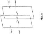
- Fig. 8 illustrated in addition to Figure 6a that a respective surface normal 49 of the first gap wall 14a and the second gap wall 14b of the gap between the first segment 13b and the second segment 13a at an angle relative to a radial line of the stator ring 7 which is smaller than 45 °, which is mainly suitable for absorbing forces in the circumferential direction.
- Figure 6b shows a schematic representation of a sectional view of a second embodiment of a bar 41, in which a damping element 43 according to the invention is arranged, with a partial view of a segment plate 21 and the stator ring 7.
- the form-locking element 37 of the stator ring 7, in particular the bar 41 is with the form-locking element 35 of the segment plate 21 in positive engagement.
- the bar 41 is in positive contact with the stator ring 7 in the assembled state.
- the respective surface normal 49 see again Fig. 8 ) the first gap wall 14a and the second gap wall 14b of the gap between the first segment 41b and the second segment 41a extend at an angle relative to a radial line of the stator ring 7 which is greater than 45 °. In this case, forces are mainly absorbed in the radial direction.
- Fig. 7 shows a schematic representation of a sectional view of a third embodiment of a bar 45, in which a damping element 47 according to the invention is arranged, with a partial view of a segment plate 21 and the stator ring 7.
- the form-locking element 37 of the stator ring 7, in particular the bar 45 is with the form-locking element 35 of the segment plate 21 in positive engagement.
- the bar 45 is in positive contact with the stator ring 7 in the assembled state.
- the bar 45 is constructed in three parts with a first segment 45b, a second segment 45a and a third segment 45c.
- the first segment 45b and the third segment 45c are arranged axially symmetrically to a radial line of the stator ring 7 and adjacent to a second segment 45a. Between the first segment 45b and the second segment 45a and between the second segment 45a and the third segment 45c there is a gap in each of which a damping element 47 is arranged.
- the gap extends along the longitudinal axis L1 of the strip 45 and has an arcuate course in the radial plane.
- the second segment 45a has a curvature 25 in the circumferential direction, in particular convexly curved projections, on each of its second gap walls 14b arranged at a distance from one another in the circumferential direction.
- a corresponding recess on a first gap wall 14a of the first segment 45b and a corresponding recess on a first gap wall 14a of the third segment 45c adjoin the curved projections, in particular spaced parallel to it corresponding to the gap width.
- the damping element 47 is arranged within the gap extending between the segments (45a, 45b, 45c), in particular between the respective first gap wall 14a and the respective second gap wall 14b, at least in sections along the curvature 25.
Abstract
Die Erfindung betrifft einen Generatorstator (5) einer Windenergieanlage (100) mit einem Statorring (7) undeinem Statorblechpaket (15), wobei das Statorblechpaket (15) mehrere Segmentbleche (21) umfasst, die in Umfangsrichtung am Statorring (7) angeordnet sind,wobei der Statorring (7) und die Segmentbleche (21) korrespondierende Formschlusselemente (35, 37) aufweisen, die miteinander in Eingriff stehen und einen Kraftflusspfad zwischen dem Statorring (7) und den Segmentblechen (21) definieren,dadurch gekennzeichnet, dassmindestens eines der Formschlusselemente (35, 37) mit mindestens einem Dämpfungselement (23, 43, 47) wirkverbunden ist, welches in dem Kraftflusspfad angeordnet und dazu eingerichtet ist, eine Relativbewegung zwischen dem Statorring (7) und den Segmentblechen (21) zu dämpfen.The invention relates to a generator stator (5) of a wind turbine (100) with a stator ring (7) and a stator lamination stack (15), the stator lamination stack (15) comprising several segment plates (21) which are arranged in the circumferential direction on the stator ring (7), whereby the stator ring (7) and the segment plates (21) have corresponding form-locking elements (35, 37) which are in engagement with one another and define a force flow path between the stator ring (7) and the segment plates (21), characterized in that at least one of the form-locking elements ( 35, 37) is operatively connected to at least one damping element (23, 43, 47) which is arranged in the force flow path and is set up to damp a relative movement between the stator ring (7) and the segment plates (21).
Description
Die Erfindung betrifft einen Generatorstator einer Windenergieanlage mit einem Statorring und einem Statorblechpaket, wobei das Statorblechpaket mehrere Segmentbleche umfasst, die in Umfangsrichtung am Statorring angeordnet sind, wobei der Statorring und die Segmentbleche korrespondierende Formschlusselemente aufweisen, die miteinander in Eingriff stehen und einen Kraftflusspfad zwischen dem Statorring und den Segmentblechen definieren.The invention relates to a generator stator of a wind turbine with a stator ring and a stator lamination stack, the stator lamination stack comprising a plurality of segment plates which are arranged in the circumferential direction on the stator ring, the stator ring and the segment plates having corresponding form-locking elements which are in engagement with one another and a power flow path between the stator ring and define the segment plates.
Die Erfindung betrifft ferner einen Generator einer Windenergieanlage, insbesondere einen langsam drehenden Synchron-Ringgenerator, mit einem Generatorstator der eingangs genannten Art, und einem relativ zu dem Generatorstator drehbar gelagerten Generatorrotor.The invention also relates to a generator of a wind power installation, in particular a slowly rotating synchronous ring generator, with a generator stator of the type mentioned at the beginning and a generator rotor mounted rotatably relative to the generator stator.
Die Erfindung betrifft weiterhin eine Windenergieanlage, insbesondere getriebelose Windenergieanlage, mit einem Turm, einer auf dem Turm drehbar angeordneten Gondel, einer drehbar an der Gondel gelagerten Nabe mit einer Anzahl von Rotorblättern, und einem Generator der eingangs genannten Art zur Bereitstellung elektrischer Energie, der einen mit der Nabe verbundenen Generatorrotor aufweist.The invention further relates to a wind turbine, in particular a gearless wind turbine, with a tower, a nacelle rotatably arranged on the tower, a hub rotatably mounted on the nacelle with a number of rotor blades, and a generator of the type mentioned above for providing electrical energy, the one having generator rotor connected to the hub.
Windenergieanlagen sind allgemein gekannt. Sie weisen einen Turm auf, auf dem eine Gondel drehbar gelagert ist. Die Gondel weist, häufig im Inneren, einen Maschinenträger auf, einen Generator, eine Antriebswelle für den Generator, optional ein Getriebe, und eine Rotornabe mit einer Anzahl von Rotorblättern, die zum Antrieb des Generators im Wind rotieren. Der Generator weist üblicherweise einen von dem Maschinenträger getragenen Generatorstator und einen relativ zu dem Generatorstator, vorzugsweise innen oder außen, umlaufenden Generatorrotor auf.Wind turbines are generally known. They have a tower on which a gondola is rotatably mounted. The nacelle has, often inside, a machine carrier, a generator, a drive shaft for the generator, optionally a gearbox, and a rotor hub with a number of rotor blades that rotate in the wind to drive the generator. The generator usually has a generator stator carried by the machine carrier and a generator rotor rotating relative to the generator stator, preferably inside or outside.
Generatorstatoren der vorbezeichneten Art sind grundsätzlich bekannt. Sie weisen üblicherweise ein Segmentblechpaket mit einer Vielzahl von Nuten zur Aufnahme einer Statorwicklung auf, in welcher durch einen an ihr entlang laufender Generatorrotor eine elektrische Leistung induziert wird.Generator stators of the aforementioned type are known in principle. They usually have a segmented laminated core with a large number of slots for receiving a stator winding, in which an electrical power is induced by a generator rotor running along it.
Der Generatorrotor weist eine Vielzahl von Polschuhen auf. Die Polschuhe laufen relativ zu den Statorwicklungen des Generatorstators um. Zwischen den Polschuhen und den Wicklungen des Generatorstators ist ein Luftspalt ausgebildet, der möglichst schmal ist. Über ein Erregerfeld im Generatorrotor wird im Generatorstator eine Spannung induziert.The generator rotor has a plurality of pole pieces. The pole shoes rotate relative to the stator windings of the generator stator. An air gap that is as narrow as possible is formed between the pole shoes and the windings of the generator stator. A voltage is induced in the generator stator via an excitation field in the generator rotor.
Aufgrund des sich drehenden, immer leicht unstetig verhaltenden Erregerfeldes entstehen Drehmomentschwankungen. Diese Drehmomentschwankungen weisen üblicherweise eine von der Drehzahl des Generatorrotors abhängige Frequenz auf und können Schwingungen im Generator verursachen.Torque fluctuations occur due to the rotating exciter field, which is always slightly unsteady. These torque fluctuations usually have a frequency that is dependent on the speed of the generator rotor and can cause oscillations in the generator.
Diese im Generator erzeugten Schwingungen werden über die Tragstruktur und den Nabenflansch auf die Hauptwelle der Windenergieanlage übertragen und über diese durch die Rotornabe bis in die Rotorblätter.These vibrations generated in the generator are transmitted via the support structure and the hub flange to the main shaft of the wind turbine and via this through the rotor hub into the rotor blades.
Da Windenergieanlagen zunehmend auch in der Nähe besiedelter Gebiete errichtet werden, liegt ein besonderes Augenmerk auf der möglichst weitgehenden Vermeidung störender Schallemissionen.Since wind turbines are increasingly being built in the vicinity of populated areas, special attention is paid to avoiding disturbing noise emissions as far as possible.
Des Weiteren führt die Induktion elektrischer Leistung zu einer Wärmeentwicklung im Statorring und infolgedessen zu einer Ausdehnung der Segmentbleche. Die Größenschwankungen im Betrieb auszugleichen und gleichzeitig einen Formschluss des Statorblechpakets mit dem Statorring zu gewährleisten stellt weiterhin eine Herausforderung für die Windenergieanlagenhersteller dar.In addition, the induction of electrical power leads to heat development in the stator ring and consequently to an expansion of the segment plates. Compensating for size fluctuations during operation and at the same time ensuring a form fit between the stator core and the stator ring continues to be a challenge for wind turbine manufacturers.
Der Erfindung lag somit die Aufgabe zugrunde, einen Generatorstator der eingangs bezeichneten Art dahingehend zu verbessern, dass er die im Stand der Technik vorgefundenen Nachteile möglichst weitgehend überwindet. Insbesondere lag der Erfindung die Aufgabe zugrunde, einen Generatorstator dahingehend zu verbessern, dass die Windenergieanlage hinsichtlich des Schwingungsverhaltens verbessert wird, und insbesondere insgesamt möglichst geringe Geräuschemissionen abgibt.The invention was thus based on the object of improving a generator stator of the type indicated at the outset in such a way that it overcomes the disadvantages found in the prior art as far as possible. In particular, the invention was based on the object of improving a generator stator in such a way that the wind energy installation is improved with regard to the vibration behavior and in particular emits the lowest possible noise emissions overall.
Die Aufgabe wird in einem ersten Aspekt von einem Generatorstator der eingangs genannten Art gelöst, wobei mindestens eines der Formschlusselemente mit mindestens einem Dämpfungselement wirkverbunden ist, welches in dem Kraftflusspfad angeordnet und dazu eingerichtet ist, eine Relativbewegung zwischen dem Statorring und den Segmentblechen zu dämpfen. Mithilfe der formschlüssigen Segmentblechbefestigung ist es möglich, den Kraftfluss vom Statorblechpaket zur lasttragenden Struktur, also den Statorring, zu leiten. Durch die gezielte Ausgestaltung der Schnittstelle Blech-Statorring ist eine positive Beeinflussung der Generatoreigenschaften, insbesondere eine Minimierung der Schallemissionen, möglich. Der erfindungsgemäße Generatorstator sieht hierfür vor, ein Dämpfungselement in die Schnittstelle, insbesondere in den Kraftflusspfad, zwischen Statorring und Segmentblech, zu integrieren.The object is achieved in a first aspect by a generator stator of the type mentioned at the outset, with at least one of the form-fitting elements being operatively connected to at least one damping element which is arranged in the force flow path and is designed to dampen a relative movement between the stator ring and the segment plates. With the help of the form-fit segment sheet fastening, it is possible to direct the flow of force from the stator core to the load-bearing structure, i.e. the stator ring. The targeted design of the sheet-metal stator ring interface enables the generator properties to be positively influenced, in particular to minimize noise emissions. For this purpose, the generator stator according to the invention provides for a damping element to be integrated in the interface, in particular in the force flow path, between the stator ring and segment plate.
Vorzugsweise ist das Statorblechpaket zwischen einem oberen Druckblech und einem unteren Druckblech eingespannt, wobei die Druckbleche mit dem Statorring nach Art einer Fest-/Loslagerung verbunden sind. Vorzugsweise sind die Druckbleche jeweils aus Druckblechsegmenten gebildet. Unter einer Fest-/Loslagerung wird hierbei verstanden, dass eines der Druckbleche in axialer Richtung des Statorringe fixiert ist, während das andere Druckblech axial nicht am Statorring fixiert ist. Durch eine solche Fest-/Loslageranordnung zusammen mit der formschlüssigen Segmentblechbefestigung ist es möglich, auf die sonst übliche Verschweißung der Druckbleche mit dem Statorring zu verzichten. Dadurch kann auf eine Befestigung mittels Schweißen verzichtet werden, was wiederum das Risiko von Generatorschäden reduziert, die beispielsweise durch das Auftreten von Schweißspritzern in der Statornut entstehen könnten. Auch die wärmebedingte Ausdehnung des Statorblechpaketes und das mechanische Setzverhalten des Blechpaketes in axialer Richtung des Statorrings werden hierdurch besser berücksichgt.The laminated stator core is preferably clamped between an upper pressure plate and a lower pressure plate, the pressure plates being connected to the stator ring in the manner of a fixed / loose mounting. The pressure plates are preferably each formed from pressure plate segments. A fixed / loose bearing is understood here to mean that one of the pressure plates is fixed in the axial direction of the stator ring, while the other pressure plate is not axially fixed on the stator ring. Such a fixed / floating bearing arrangement together with the form-fitting segment sheet fastening makes it possible to dispense with the otherwise usual welding of the pressure sheets to the stator ring. As a result, fastening by means of welding can be dispensed with, which in turn reduces the risk of generator damage that could arise, for example, from the occurrence of weld spatter in the stator slot. The thermal expansion of the stator core and the mechanical settling behavior of the core in the axial direction of the stator ring are also better taken into account.
Je nach Ausgestaltung und Anordnung des Dämpfungselementes innerhalb des Kraftflusspfades kann das Dämpfungselement sowohl Relativbewegungen in radialer als auch in Umfangsrichtung ausgleichen. Des Weiteren können mithilfe des Dämpfungselementes Fertigungstoleranzen vor allem in Umfangsrichtung ausgeglichen werden. Ein Segmentblech bildet innerhalb des Statorrings einen Kreisbogenabschnitt. Zur Erzielung der Ringform werden mehrere Segmentbleche aneinandergereiht und zu einem oder mehreren Statorblechpaketen gestapelt. Um den geforderten formschlüssigen Kontakt zwischen Segmentblech und Statorring zu erreichen, können die Segmentbleche in Umfangsrichtung auf Plustoleranz gefertigt werden. Damit die Segmentbleche trotzdem passgenau in einer Ringform aneinandergereiht werden können, kann das Dämpfungselement, das in Umfangsrichtung zwischen den Segmentblechen angeordnet ist, den potentiellen Überstand ausgleichen.Depending on the design and arrangement of the damping element within the force flow path, the damping element can compensate for relative movements in the radial as well as in the circumferential direction. Furthermore, the damping element can be used to compensate for manufacturing tolerances, especially in the circumferential direction. A segment plate forms a circular arc section within the stator ring. To achieve the ring shape, several segmented laminations are strung together and stacked to form one or more stator laminations. In order to achieve the required form-fitting contact between the segment plate and the stator ring, the segment plates can be manufactured to a plus tolerance in the circumferential direction. So that the segment plates can nevertheless be lined up in a ring shape with an exact fit, the damping element, which is arranged in the circumferential direction between the segment plates, can compensate for the potential protrusion.
Erfindungsgemäß verläuft eine Längsachse des Generatorstators bzw. des Statorrings orthogonal zu der Querschnittsfläche des Generatorstators bzw. des Statorrings durch dessen Mittelpunkt. Die radiale Richtung erstreckt sich ausgehend von dem Mittelpunkt des Generatorstators orthogonal zu der Längsachse. Die Umfangsrichtung erstreckt sich orthogonal zu der radialen Richtung und zu der Längsachse des Generatorstators.According to the invention, a longitudinal axis of the generator stator or the stator ring runs orthogonally to the cross-sectional area of the generator stator or the stator ring through its center point. The radial direction extends from the center of the generator stator orthogonally to the longitudinal axis. The circumferential direction extends orthogonally to the radial direction and to the longitudinal axis of the generator stator.
Vorzugsweise weist das korrespondierende Formschlusselement des Statorrings zumindest abschnittsweise eine Wölbung auf, wobei sich die Wölbung in Umfangsrichtung des Statorrings erstreckt und wobei die Wölbung dazu eingerichtet ist, formschlüssig mit einer korrespondierenden Wölbung des korrespondierenden Formschlusselements der Segmentbleche in Eingriff zu stehen. Die Wölbung kann sowohl in Umfangsrichtung von dem Statorring bzw. einem Verbindungselement oder dem Segmentblech hervorstehen oder in Umfangsrichtung in den Statorring bzw. das Verbindungselement oder das Segmentblech eingelassen sein. Das bedeutet, dass die Wölbung als eine Ausnehmung oder ein Vorsprung ausgebildet ist. Erfindungsgemäß ist die Wölbung vorzugsweise konkav oder konvex geformt. Alternativ können die korrespondierenden Formschlusselemente auch jeweils aus einer Vielzahl an Wölbungen gebildet werden, beispielsweise aus einer Kombination aus konkaven und konvexen Wölbungen. Weitere durch die Erfindung nicht ausgeschlossene Ausgestaltungsmöglichkeiten der korrespondierenden Formschlusselemente können einen kantigen Verlauf vorsehen, beispielsweise in Form einer Spitze oder eines Rechtecks oder Vielecks oder eine Kombination daraus. Die Wölbung ist dazu eingerichtet, die Segmentbleche vor allem in radialer Richtung zu fixieren.The corresponding form-fit element of the stator ring preferably has a curvature, at least in sections, the curvature extending in the circumferential direction of the stator ring and the curvature being designed to be positively locked with a corresponding curvature of the corresponding form-locking element of the segment plates to be in engagement. The curvature can protrude in the circumferential direction from the stator ring or a connecting element or the segment plate or can be embedded in the stator ring or the connecting element or the segment plate in the circumferential direction. This means that the curvature is designed as a recess or a projection. According to the invention, the curvature is preferably concave or convex. Alternatively, the corresponding form-fit elements can also each be formed from a large number of bulges, for example from a combination of concave and convex bulges. Further design options for the corresponding form-locking elements that are not excluded by the invention can provide an angular course, for example in the form of a point or a rectangle or polygon or a combination thereof. The curvature is designed to fix the segment plates primarily in the radial direction.
Gemäß einer bevorzugten Weiterbildung umfasst der Statorring mindestens ein Verbindungselement, insbesondere in Form einer sich in Richtung einer Längsachse des Statorrings erstreckenden Verbindungsleiste, welches oder welche an dem Statorring befestigt ist, wobei das korrespondierende Formschlusselement des Statorrings ein Teil des Verbindungselements ist. Das Verbindungselement weist vorzugsweise die Form einer Leiste auf und kann allgemein auch als Schachtelleiste bezeichnet werden. Ein solches Verbindungselement bzw. eine solche Verbindungsleiste wird innenseitig an den Statorring montiert. Die Anbindung der Leiste an den Statorring kann form-, kraft- und/oder stoffschlüssig erfolgen, also beispielsweise mittels einer Schraub-, Schweiß- oder Klebverbindung.According to a preferred development, the stator ring comprises at least one connecting element, in particular in the form of a connecting strip extending in the direction of a longitudinal axis of the stator ring, which is fastened to the stator ring, the corresponding form-locking element of the stator ring being part of the connecting element. The connecting element preferably has the shape of a bar and can generally also be referred to as a box bar. Such a connecting element or such a connecting strip is mounted on the inside of the stator ring. The connection of the bar to the stator ring can take place in a form-fitting, force-fitting and / or cohesive manner, for example by means of a screw, weld or adhesive connection.
Das Verbindungselement erstreckt sich im montierten Zustand vorzugsweise in Längsrichtung zum Statorring. Besonders bevorzugt erstreckt sich das Verbindungselement parallel zu der Längsachse des Statorrings. Das Verbindungselement ist vorzugsweise derart ausgebildet, dass es im montierten Zustand mit mindestens einem Segmentblech formschlüssig in Eingriff steht.In the assembled state, the connecting element preferably extends in the longitudinal direction of the stator ring. The connecting element particularly preferably extends parallel to the longitudinal axis of the stator ring. The connecting element is preferably designed such that, in the assembled state, it is in positive engagement with at least one segment plate.
Vorzugsweise weist es auf jeder seiner Seitenflächen, die in Umfangsrichtung beabstandet zueinander sind, jeweils ein Formschlusselement auf. Hierdurch steht das Verbindungselement in Umfangsrichtung mit jeweils mindestens einem Segmentblech auf einer ersten Seite und mindestens einem zweiten Segmentblech auf einer zweiten Seite formschlüssig in Eingriff.It preferably has a form-locking element on each of its side surfaces, which are spaced apart from one another in the circumferential direction. As a result, the connecting element is in positive engagement in the circumferential direction with at least one segment plate on a first side and at least one second segment plate on a second side.
Erfindungsgemäß soll verstanden sein, dass der Begriff Formschluss oder formschlüssig auch einen aufgrund von Relativbewegungen oder sonstigen Einflüssen innerhalb des Generatorstators entstehenden Spalts inkludiert. Das Formschlusselement des Verbindungselements erstreckt sich vorzugsweise entlang einer Längsachse des Verbindungselementes, die sich in Längsrichtung des Generatorstators erstreckt, sodass mehrere übereinander gestapelte Segmentbleche mit einem Verbindungselement formschlüssig in Eingriff stehen können. Mittels der formschlüssigen Verbindung sind die Segmentbleche in Umfangsrichtung fixierbar.According to the invention, it should be understood that the term form fit or form fit also includes a gap arising within the generator stator due to relative movements or other influences. The form-locking element of the connecting element preferably extends along a longitudinal axis of the connecting element, which extends in the longitudinal direction of the generator stator, so that a plurality of segmented sheets stacked on top of one another can be positively engaged with a connecting element. The segment plates can be fixed in the circumferential direction by means of the positive connection.
Ferner ist bevorzugt, dass das Verbindungselement mehrteilig ausgebildet ist und mindestens zwei, insbesondere drei, Segmente aufweist. Mithilfe eines mehrteiligen Aufbaus des Verbindungselementes ist es in einfacher Weise möglich, ein oder mehrere Dämpfungselemente direkt innerhalb des Verbindungselementes, also jeweils zwischen zwei Segmenten, zu integrieren. Des Weiteren ermöglicht ein segmentartiger Aufbau eine hohe Variabilität der geometrischen Anordnung. Diese kann somit bedarfsgerecht angepasst werden, ohne die Geometrie der Segmentbleche oder des Statorrings verändern zu müssen. Erfindungsgemäß ist ein dreiteiliger Aufbau des Verbindungselementes vorgesehen. Dieser ist für eine achsensymmetrische Ausrichtung an einer Radialen des Statorrings vorteilhaft.It is further preferred that the connecting element is designed in several parts and has at least two, in particular three, segments. With the aid of a multi-part construction of the connecting element, it is possible in a simple manner to integrate one or more damping elements directly within the connecting element, that is to say between two segments in each case. Furthermore, a segment-like structure enables a high degree of variability in the geometric arrangement. This can therefore be adapted as required without having to change the geometry of the segment plates or the stator ring. According to the invention, a three-part structure of the connecting element is provided. This is advantageous for an axially symmetrical alignment on a radial line of the stator ring.
In einer weiteren bevorzugten Ausführungsform erstreckt sich zwischen mindestens zwei benachbarten Segmenten ein Spalt mit einer ersten Spaltwand an einem ersten Segment und einer zweiten Spaltwand an einem zweiten Segment, wobei mindestens eines der Dämpfungselemente zwischen der ersten und der zweiten Spaltwand angeordnet ist. Vorzugsweise ist ein Dämpfungselement zwischen zwei benachbarten Segmenten angeordnet. Das heißt, das Dämpfungselement ist insbesondere in einem Spalt, der sich zwischen zwei benachbarten Segmenten in Längsrichtung des Statorrings erstreckt, angeordnet.In a further preferred embodiment, a gap extends between at least two adjacent segments with a first gap wall on a first segment and a second gap wall on a second segment, at least one of the damping elements being arranged between the first and the second gap wall. A damping element is preferably arranged between two adjacent segments. That is to say, the damping element is arranged in particular in a gap which extends between two adjacent segments in the longitudinal direction of the stator ring.
Das Dämpfungselement ist mit den sich entlang des Spalts erstreckenden Spaltwänden vorzugsweise formschlüssig verbunden. Hierbei kann das Dämpfungselement auch abschnittsweise innerhalb des Spalts angeordnet sein. Des Weiteren erstrecken sich vorzugsweise ein oder mehrere Dämpfungselemente innerhalb des Spalts. Außerdem kann der Spalt sich über mehrere benachbart zueinander angeordnete Segmente erstrecken. Vorzugsweise weist der Spalt zwei parallel beabstandet zueinander angeordnete Spaltflächen auf.The damping element is preferably positively connected to the gap walls extending along the gap. Here the damping element can also be arranged in sections within the gap. Furthermore, one or more damping elements preferably extend within the gap. In addition, the gap can extend over a plurality of segments arranged adjacent to one another. The gap preferably has two gap surfaces which are arranged parallel to one another and spaced apart from one another.
Bevorzugt sind ein erstes Segment und ein zweites Segment mit einem ersten Dämpfungselement verbunden, und das zweite Segment und ein drittes Segment mit einem zweiten Dämpfungselement verbunden. Eine derartige Anordnung der Segmente ermöglicht eine achsensymmetrisch zu einer Radialen ausgerichtete Verbindungselementanordnung. Das erste Dämpfungselement, welches zwischen einem ersten Segment und einem zweiten Segment angeordnet ist, soll somit Relativbewegungen eines an das erste Segment angrenzenden Segmentblechs dämpfen. Das zweite Dämpfungselement, welches zwischen dem zweiten Segment und dem dritten Segment angeordnet ist, dämpft Relativbewegungen von Segmentblechen, die in Umfangsrichtung gegenüberliegend auf der zweiten Seite des Verbindungselements, also angrenzend an das dritte Segment, angeordnet sind.A first segment and a second segment are preferably connected to a first damping element, and the second segment and a third segment to a second Damping element connected. Such an arrangement of the segments enables a connecting element arrangement that is axially symmetrical to a radial. The first damping element, which is arranged between a first segment and a second segment, is thus intended to dampen relative movements of a segment plate adjoining the first segment. The second damping element, which is arranged between the second segment and the third segment, damps relative movements of segment plates which are arranged opposite one another in the circumferential direction on the second side of the connecting element, i.e. adjacent to the third segment.
In einerweiteren bevorzugten Ausführungsform weist jede Spaltwand mindestens eine Flächennormale, ausgehend von einem Mittelpunkt der Spaltwand, auf, wobei die Flächennormale jeweils eine Komponente in radialer Richtung und in Umfangsrichtung aufweist und sich in einem Winkel relativ zu der Radialen des Statorrings erstreckt. Die Ausrichtung der Spaltwände innerhalb des Verbindungselementes hat einen direkten Einfluss auf die Ausrichtung des zwischen den Spaltwänden angeordneten Dämpfungselementes und somit einen Einfluss auf die Dämpfungseigenschaften. Je nachdem in welchem Winkel der Spalt relativ zu einer Radialen angeordnet ist, werden vorzugsweise radiale oder tangentiale Kräfte aufgenommen. Die Bestimmung des Winkels erfolgt über die Flächennormale der Spaltwand. Die Flächennormale erstreckt sich ausgehend von einem Flächenmittelpunkt der Spaltwand.In a further preferred embodiment, each gap wall has at least one surface normal, starting from a center point of the gap wall, the surface normal each having a component in the radial direction and in the circumferential direction and extending at an angle relative to the radial line of the stator ring. The alignment of the gap walls within the connecting element has a direct influence on the alignment of the damping element arranged between the gap walls and thus an influence on the damping properties. Depending on the angle at which the gap is arranged relative to a radial, radial or tangential forces are preferably absorbed. The angle is determined using the surface normal of the split wall. The surface normal extends from a surface center point of the gap wall.
Bevorzugt ist der Winkel größer 45°, wobei der Winkel vorzugsweise in einem Bereich von 50° bis 85° liegt. In einer weiteren bevorzugten Ausführungsform ist der Winkel kleiner 45°, wobei der Winkel vorzugsweise in einem Bereich von 5° bis 40° liegt. Für die Bestimmung des Winkels, ist die Flächennormale einer Spaltwand relativ zu einer Radialen des Statorrings, die den Flächenmittelpunkt der Spaltwand kreuzt, insbesondere ein Winkel kleiner oder gleich 90°, zu verwenden. Prinzipiell ist der Winkel relativ zu einer Radialen der Flächennormale der ersten Spaltwand unterschiedlich zu einem Winkel zwischen der Flächennormalen und einer Radialen der zweiten Spaltwand, zwischen denen sich das Dämpfungselement erstreckt. Parameter, die den Unterschied beeinflussen, sind im Wesentlichen die Breite und die Länge des Spalts in der Ebene, die sich durch die beiden Radialen erstreckt. Dieser Winkelunterschied ist aufgrund der Dimension des Statorrings im Verhältnis zu der Dimension der Spaltwand, die um ein Vielfaches kleiner ist, vernachlässigbar klein. Hilfsweise ist der Mittelwert der beiden Winkel, also des Winkels zwischen der ersten Radialen und der Flächennormalen der ersten Spaltwand, und des Winkels der zweiten Radialen und der Flächennormale der zweiten Spaltwand, zu bilden.The angle is preferably greater than 45 °, the angle preferably being in a range from 50 ° to 85 °. In a further preferred embodiment, the angle is less than 45 °, the angle preferably being in a range from 5 ° to 40 °. To determine the angle, the surface normal of a gap wall relative to a radial line of the stator ring that crosses the center of the surface of the gap wall, in particular an angle less than or equal to 90 °, is to be used. In principle, the angle relative to a radial line of the surface normal of the first gap wall is different from an angle between the surface normal and a radial line of the second gap wall, between which the damping element extends. Parameters that influence the difference are essentially the width and length of the gap in the plane that extends through the two radials. This angle difference is negligibly small due to the dimension of the stator ring in relation to the dimension of the gap wall, which is many times smaller. Alternatively, the mean value of the two angles, that is to say the angle between the first radial and the surface normal of the first gap wall, and the angle of the second radial and the surface normal of the second gap wall, is to be formed.
Je nach Anforderung kann der Winkel beispielsweise größer 45° oder kleiner 45° sein. Unabhängig von der Spaltdicke sowie der Länge des Dämpfungselementes, kann das Dämpfungselement je nach Ausrichtung sowohl Kräfte in Umfangsrichtung als auch Kräfte in radialer Richtung aufnehmen. Das bedeutet, für Winkel größer 45° können in größerem Maße tangentiale Kräfte aufgenommen werden, für Winkel kleiner 45° in größerem Maße radiale Kräfte. Unabhängig von dem Winkelbereich, ist ein weiterer entscheidender Faktor die Breite und Dicke des Dämpfungselementes innerhalb des Spaltes. Je nach Ausprägung in der jeweiligen Richtung, kann die Aufnahme von Kräften in tangentialer und in radialer Richtung begrenzt sein. Ausgenommen hiervon bleibt die Bewegungsfähigkeit der einzelnen Segmente. Es soll verstanden sein, dass zum Aufnehmen von Kräften in tangentialer und in radialer Richtung, eine Bewegungsfreiheit der Segmente mit dem Dämpfungselement in die jeweilige Richtung eine Grundvoraussetzung ist.Depending on the requirement, the angle can be greater than 45 ° or less than 45 °, for example. Regardless of the gap thickness and the length of the damping element, the damping element can absorb both forces in the circumferential direction and forces in the radial direction, depending on the orientation. This means that tangential forces can be absorbed to a greater extent for angles greater than 45 °, and radial forces to a greater extent for angles smaller than 45 °. Regardless of the angular range, another decisive factor is the width and thickness of the damping element within the gap. Depending on the characteristics in the respective direction, the absorption of forces can be limited in the tangential and in the radial direction. The mobility of the individual segments is excluded from this. It should be understood that for the absorption of forces in the tangential and in the radial direction, freedom of movement of the segments with the damping element in the respective direction is a basic requirement.
In einer weiteren bevorzugten Ausführungsform ist mindestens eine der Spaltwände zumindest abschnittsweise konvex und/oder konkav gewölbt. Hierdurch ergibt sich eine vergrößerte Oberfläche der Spaltwände, wodurch eine verbesserte Haftung von der Oberfläche des Dämpfungselementes an der Spaltwand erzielt werden kann.In a further preferred embodiment, at least one of the gap walls is curved convexly and / or concavely at least in sections. This results in an enlarged surface of the gap walls, whereby improved adhesion of the surface of the damping element to the gap wall can be achieved.
Ferner ist bevorzugt, dass beide der Spaltwände zumindest abschnittsweise konvex und/oder konkav gewölbt sind, derart, dass ein konvexer Abschnitt der ersten Spaltwand einem konkaven Abschnitt der zweiten Spaltwand gegenübersteht und/oder ein konkaver Abschnitt der ersten Spaltwand einem konvexen Abschnitt derzweiten Spaltwand gegenübersteht, sodass sich ein bogenförmiger oder mäanderförmiger Spalt ergibt. Je nach Verlauf und Form des Spalts, können die Dämpfungseigenschaften gezielt beeinflusst werden. Beispielsweise kann ein mäanderförmiger Spalt zu einer Vergleichmäßigung der übertragenen Kräfte beitragen.It is further preferred that both of the gap walls are at least partially convex and / or concave, such that a convex section of the first gap wall faces a concave section of the second gap wall and / or a concave section of the first gap wall faces a convex section of the second gap wall, so that there is an arcuate or meander-shaped gap. Depending on the course and shape of the gap, the damping properties can be specifically influenced. For example, a meandering gap can help to make the forces transmitted more even.
In einem weiteren Aspekt der Erfindung ist der Querschnitt des zweiten Segments im Wesentlichen trichterförmig ausgebildet, wobei das erste Segment und das dritte Segment benachbart zu dem zweiten Segment angeordnet und zu der Mittelachse des Querschnitts des zweiten Segments achsensymmetrisch angeordnet sind.In a further aspect of the invention, the cross-section of the second segment is essentially funnel-shaped, the first segment and the third segment being arranged adjacent to the second segment and being arranged axially symmetrically to the central axis of the cross-section of the second segment.
Als trichterförmig wird hierin verstanden, dass ein erster trapezförmiger Abschnitt an einen zweiten rechteckigen Abschnitt grenzt, wobei der erste Abschnitt zwei gegenüberliegende Wände aufweist, die aufeinander zulaufen und der zweite darauffolgende Abschnitt parallel zueinander, insbesondere achsensymmetrisch zu einer Radialen, verlaufende Wände aufweist.Funnel-shaped is understood here to mean that a first trapezoidal section adjoins a second rectangular section, the first section having two opposing walls that converge and the second subsequent section having walls running parallel to one another, in particular axially symmetrical to a radial.
In einer weiteren bevorzugten Ausführungsform ist das Dämpfungselement als ein Flachkörper ausgebildet. Dieser ist in einfacher Weise herstellbar.In a further preferred embodiment, the damping element is designed as a flat body. This can be produced in a simple manner.
Unter einem Flachkörper soll erfindungsgemäß ein Körper verstanden werden, dessen Länge und Breite um ein Vielfaches größer ist als dessen Dicke. Innerhalb des Statorrings, insbesondere innerhalb des Spalts des Verbindungselementes erstreckt sich die Länge des Flachkörpers parallel zu der Längsachse des Verbindungselementes, insbesondere in Richtung der Längsachse des Generatorstators. Die Breite des Flachkörpers erstreckt sich zumindest abschnittsweise entlang der Spaltwände und die Dicke erstreckt sich entlang eines Spaltabstands, insbesondere von der ersten Spaltwand zu der zweiten Spaltwand.According to the invention, a flat body should be understood to mean a body whose length and width are many times greater than its thickness. Within the stator ring, in particular within the gap of the connecting element, the length of the flat body extends parallel to the longitudinal axis of the connecting element, in particular in the direction of the longitudinal axis of the generator stator. The width of the flat body extends at least in sections along the gap walls and the thickness extends along a gap distance, in particular from the first gap wall to the second gap wall.
In einem zweiten Aspekt wird die der Erfindung zu Grunde liegenden Aufgabe durch einen Generator einer Windenergieanlage, gelöst, wobei der Generatorstator nach einer der vorstehend beschriebenen bevorzugten Ausführungsformen ausgebildet ist.In a second aspect, the object on which the invention is based is achieved by a generator of a wind energy installation, the generator stator being designed according to one of the preferred embodiments described above.
In einem dritten Aspekt wird die der Erfindung zu Grunde liegenden Aufgabe durch eine Windenergieanlage, insbesondere getriebelose Windenergieanlage, gelöst, wobei der Generator nach einer der vorstehend beschriebenen bevorzugten Ausführungsform ausgebildet ist.In a third aspect, the object on which the invention is based is achieved by a wind energy installation, in particular a gearless wind energy installation, the generator being designed according to one of the preferred embodiments described above.
Es soll verstanden werden, dass die bevorzugten Ausführungsformen und Vorteile des Generatorstators zugleich bevorzugte Ausführungsformen und Vorteile des Generators gemäß dem zweiten Aspekt, sowie der Windenergieanlage gemäß dem dritten Aspekt sind, sodass zur Vermeidung von Wiederholungen auf das oben Stehende verwiesen wird.It should be understood that the preferred embodiments and advantages of the generator stator are at the same time preferred embodiments and advantages of the generator according to the second aspect and the wind power installation according to the third aspect, so that reference is made to the above to avoid repetition.
Die Erfindung ist nachstehend anhand von Ausführungsbeispielen unter Bezugnahme auf die Figuren beschrieben. Es zeigen:
- Figur 1:
- eine schematische perspektivische Ansicht einer Windenergieanlage.
- Figur 2:
- eine schematische Teilschnittansicht einer Gondel der Windenergieanlage gem.
Fig.1 . - Figur 3a:
- eine schematische Teilansicht eines Generatorstators der Windenergieanlage gem.
Fig.1 und2 mit einem unteren Druckblechsegment. - Figur 3b:
- eine schematische Teilansicht eines Generatorstators der Windenergieanlage gem.
Fig.1 und2 mit einem oberen Druckblechsegment. - Figur 4:
- eine schematische Schnittdarstellung einer Teilansicht eines Generatorstators der Windenergieanlage gem.
Fig.1 und2 . - Figur 5:
- eine schematische perspektivische Ansicht eines Verbindungselementes der Windenergieanlage gem.
Fig.1 und2 und eine schematische Schnittdarstellung der Windenergieanlage gem.Fig.1 und2 . - Figur 6a:
- eine schematische Schnittdarstellung des ersten Ausführungsbeispiels des Verbindungselementes gem.
Fig. 5 . - Figur 6b:
- eine schematische Schnittdarstellung eines zweiten Ausführungsbeispiels eines Verbindungselementes.
- Figur 7:
- eine schematische Schnittdarstellung eines dritten Ausführungsbeispiels eines Verbindungselementes.
- Figur 8:
- eine schematische Darstellung einer ersten und zweiten Spaltwand des Verbindungselementes gem.
Fig. 6 .
- Figure 1:
- a schematic perspective view of a wind turbine.
- Figure 2:
- a schematic partial sectional view of a nacelle of the wind turbine according to FIG.
Fig.1 . - Figure 3a:
- a schematic partial view of a generator stator of the wind turbine according to FIG.
Fig.1 and2 with a lower pressure plate segment. - Figure 3b:
- a schematic partial view of a generator stator of the wind turbine according to FIG.
Fig.1 and2 with an upper pressure plate segment. - Figure 4:
- a schematic sectional illustration of a partial view of a generator stator of the wind energy installation according to FIG.
Fig.1 and2 . - Figure 5:
- a schematic perspective view of a connecting element of the wind turbine according to FIG.
Fig.1 and2 and a schematic sectional view of the wind energy installation according to FIG.Fig.1 and2 . - Figure 6a:
- a schematic sectional view of the first embodiment of the connecting element according to FIG.
Fig. 5 . - Figure 6b:
- a schematic sectional view of a second embodiment of a connecting element.
- Figure 7:
- a schematic sectional view of a third embodiment of a connecting element.
- Figure 8:
- a schematic representation of a first and second gap wall of the connecting element according to FIG.
Fig. 6 .
Einander entsprechende Teile sind in allen Zeichnungsfiguren mit den gleichen Bezugszeichen versehen.Corresponding parts are provided with the same reference symbols in all drawing figures.
Die Gondel 104 der Windenergieanlage 100 gemäß
Der Generator 1 weist einen Generatorstator 5 auf, der mittels des Achszapfens 114 an dem Maschinenträger 116 in der Gondel 104 befestigt ist. Andere, durch die Erfindung nicht ausgeschlossene Ausgestaltungsmöglichkeiten sehen beispielsweise vor, den Generatorstator 5 unmittelbar an den Maschinenträger 116 oder ein entsprechendes Bauteil der Gondel 104 anzubinden.The generator 1 has a generator stator 5 which is fastened to the
Der Generator 1 gemäß
Der nähere Aufbau des Generatorstators 5 ist in
In dem Statorring 7 ist eine Vielzahl von plattenförmigen Segmentblechen 21 (
Das Statorblechpaket 15 besteht aus einer Vielzahl von Segmentblechen 21, von denen eines schematisch in
Die Leiste 13 umfasst drei Segmente (13a, 13b, 13c). Die drei Segmente (13a, 13b, 13c) sind, insbesondere im montierten Zustand in der radialen Ebene, orthogonal zu der Längsachse L1 der Leiste 13 separiert voneinander und weisen einen sich jeweils zwischen zwei Segmenten (13b und 13a; 13a und 13c) erstreckenden Spalt auf. Der Spalt wird jeweils durch eine erste Spaltwand 14a eines ersten Segments (13b, 13c) und einer zweiten Spaltwand 14b eines zweiten Segments 13a begrenzt. Zwischen den Segmenten (13a, 13b, 13c), insbesondere zwischen zwei Spaltwänden 14, ist jeweils ein Dämpfungselement 23 angeordnet.The
Das Dämpfungselement 23 ist im gezeigten Ausführungsbeispiel als Flachkörper ausgebildet und erstreckt sich entlang der Längsachse L1, parallel zu der Längsachse L des Statorrings, vorzugsweise entlang der gesamten Länge, der Leiste 13. Das Dämpfungselement besteht aus einem elastischen, vorzugsweise gummiähnlichen Material zur Erzielung einer schlag-, stoß-, schwingungs- und vibrationsdämpfenden Wirkung.The damping
Die Leiste weist mehrere entlang ihrer Längsachse L1 angeordnete Durchgangsbohrungen 39 auf, die dazu eingerichtet sind, jeweils eine Schraube zur Befestigung der Leiste 13 am Statorring 7 aufzunehmen. Die Durchgangsbohrungen 39 sind in dem zweiten Segment 13a angeordnet.The bar has a plurality of through
Weiterhin weisen die äußeren Segmente, in dem gezeigten Ausführungsbeispiel also das erste Segment 13b und das dritte Segment 13c, der Leiste 13 jeweils an ihrer äußeren Seitenfläche (27a, 27b) jeweils eine sich entlang der Längsachse L1 der Leiste 13 erstreckende, insbesondere im montierten Zustand in Umfangsrichtung zum Statorring 7 konkav ausgebildete, Ausnehmung auf. Die Ausnehmung des ersten Segments 13b und die Ausnehmung des dritten Segments 13c bilden hier jeweils ein Formschlusselement 37 des Statorrings. Die Formschlusselemente 37 des Statorrings 7 sind mit korrespondierenden Formschlusselementen 35 der Segmentbleche 21, die hier als konvexe Vorsprünge ausgebildet sind, formschlüssig in Eingriff bringbar.Furthermore, the outer segments, in the embodiment shown, the
Die Leiste 45 ist dreiteilig aufgebaut mit einem ersten Segment 45b, einem zweiten Segment 45a und einem dritten Segment 45c. Das erste Segment 45b und das dritte Segment 45c sind achsensymmetrisch zu einer Radialen des Statorrings 7 und benachbart zu einem zweiten Segment 45a angeordnet. Zwischen dem ersten Segment 45b und dem zweiten Segment 45a sowie zwischen dem zweiten Segment 45a und dem dritten Segment 45c erstreckt sich jeweils ein Spalt in dem jeweils ein Dämpfungselement 47 angeordnet ist.The bar 45 is constructed in three parts with a
Der Spalt erstreckt sich entlang der Längsachse L1 der Leiste 45 und weist in der radialen Ebene einen bogenförmigen Verlauf auf. Insbesondere weist das zweite Segment 45a an jeder seiner in Umfangsrichtung beabstandet zueinander angeordneten zweiten Spaltwände 14b eine Wölbung 25 in Umfangsrichtung auf, insbesondere konvex gewölbte Vorsprünge. An die gewölbten Vorsprünge schließt sich, insbesondere parallel entsprechend der Spaltbreite beabstandet dazu, eine korrespondierende Ausnehmung an einer ersten Spaltwand 14a des ersten Segments 45b an und eine korrespondierende Ausnehmung an einer ersten Spaltwand 14a des dritten Segments 45c an. Das Dämpfungselement 47 ist innerhalb des sich zwischen den Segmenten (45a, 45b, 45c) erstreckenden Spalts, insbesondere zwischen der jeweiligen ersten Spaltwand 14a und der jeweiligen zweiten Spaltwand 14b, zumindest abschnittsweise entlang der Wölbung 25 angeordnet.The gap extends along the longitudinal axis L1 of the strip 45 and has an arcuate course in the radial plane. In particular, the
- 11
- Generatorgenerator
- 33
- GeneratorrotorGenerator rotor
- 55
- GeneratorstatorGenerator stator
- 66th
- StatortragstrukturStator support structure
- 77th
- StatorringStator ring
- 99
- unteres Druckblechsegmentlower pressure plate segment
- 1111
- AusnehmungRecess
- 1313
- Leiste mit Segmenten (13a, 13b, 13c)Bar with segments (13a, 13b, 13c)
- 1414th
- Spaltwand (14a, 14b)Split wall (14a, 14b)
- 1515th
- StatorblechpaketStator core
- 1717th
- oberes Druckblechsegmentupper pressure plate segment
- 1919th
- AussparungRecess
- 2121st
- SegmentblechSegment sheet
- 2323
- DämpfungselementDamping element
- 2525th
- WölbungBulge
- 2727
- Seitenfläche der Leiste (27a, 27b)Side surface of the bar (27a, 27b)
- 2929
- AussparungRecess
- 3131
- DurchgangsöffnungenThrough openings
- 3333
- AusnehmungRecess
- 3535
- Formschlusselement des SegmentblechesForm-fit element of the segment sheet
- 3737
- Formschlusselement des StatorringsForm-fit element of the stator ring
- 3939
- DurchgangsbohrungThrough hole
- 4141
- Leiste mit Segmenten (41a, 41b, 41c)Bar with segments (41a, 41b, 41c)
- 4343
- DämpfungselementDamping element
- 4545
- Leiste mit Segmenten (45a, 45b, 45c)Bar with segments (45a, 45b, 45c)
- 4747
- DämpfungselementDamping element
- 4949
- Flächennormale (49a, 49b)Surface normals (49a, 49b)
- 100100
- WindenergieanlageWind turbine
- 102102
- Turmtower
- 104104
- Gondelgondola
- 106106
- Rotorrotor
- 108108
- RotorblätterRotor blades
- 110110
- Spinnercrackhead
- 112112
- AzimutantriebAzimuth drive
- 114114
- AchszapfenJournal
- 116116
- MaschinenträgerMachine carrier
- LL.
- Längsachse des Generatorstators bzw. des StatorringsLongitudinal axis of the generator stator or the stator ring
- L1L1
- Längsachse der LeisteLongitudinal axis of the bar
Claims (15)
einem Statorring (7) und
einem Statorblechpaket (15), wobei das Statorblechpaket (15) mehrere Segmentbleche (21) umfasst, die in Umfangsrichtung am Statorring (7) angeordnet sind,
wobei der Statorring (7) und die Segmentbleche (21) korrespondierende Formschlusselemente (35, 37) aufweisen, die miteinander in Eingriff stehen und einen Kraftflusspfad zwischen dem Statorring (7) und den Segmentblechen (21) definieren,
dadurch gekennzeichnet, dass
mindestens eines der Formschlusselemente (35, 37) mit mindestens einem Dämpfungselement (23, 43, 47) wirkverbunden ist, welches in dem Kraftflusspfad angeordnet und dazu eingerichtet ist, eine Relativbewegung zwischen dem Statorring (7) und den Segmentblechen (21) zu dämpfen.Generator stator (5) of a wind energy installation (100)
a stator ring (7) and
a laminated stator core (15), the laminated stator core (15) comprising several segmented sheets (21) which are arranged in the circumferential direction on the stator ring (7),
wherein the stator ring (7) and the segment plates (21) have corresponding form-locking elements (35, 37) which are in engagement with one another and define a force flow path between the stator ring (7) and the segment plates (21),
characterized in that
at least one of the form-fit elements (35, 37) is operatively connected to at least one damping element (23, 43, 47) which is arranged in the force flow path and is designed to dampen a relative movement between the stator ring (7) and the segment plates (21).
dadurch gekennzeichnet, dass das korrespondierende Formschlusselement (37) des Statorrings (7) zumindest abschnittsweise eine Wölbung aufweist, wobei sich die Wölbung in Umfangsrichtung des Statorrings (7) erstreckt und wobei die Wölbung dazu eingerichtet ist, formschlüssig mit einer korrespondierenden Wölbung des korrespondierenden Formschlusselements (35) der Segmentbleche (21) in Eingriff zu stehen.Generator stator (5) according to claim 1,
characterized in that the corresponding form-fit element (37) of the stator ring (7) has at least some sections of a curvature, the curvature extending in the circumferential direction of the stator ring (7) and the curvature being designed to interlock with a corresponding curvature of the corresponding form-fitting element ( 35) of the segment plates (21) to be in engagement.
dadurch gekennzeichnet, dass der Statorring (7) mindestens ein Verbindungselement (13, 41, 45) umfasst, insbesondere in Form einer sich in Richtung einer Längsachse (L) des Statorrings erstreckenden Verbindungsleiste, welches oder welche an dem Statorring (7) befestigt ist, wobei das korrespondierende Formschlusselement (37) des Statorrings (7) ein Teil des Verbindungselements (13, 41, 45) ist.Generator stator (5) according to claim 1 or 2,
characterized in that the stator ring (7) comprises at least one connecting element (13, 41, 45), in particular in the form of a connecting strip which extends in the direction of a longitudinal axis (L) of the stator ring and which is fastened to the stator ring (7), wherein the corresponding form-locking element (37) of the stator ring (7) is part of the connecting element (13, 41, 45).
dadurch gekennzeichnet, dass das Verbindungselement (13, 41, 45) mehrteilig ausgebildet ist und mindestens zwei, insbesondere drei, Segmente (13a, 13b, 13c; 41a, 41b, 41c; 45a, 45b, 45c) aufweist.Generator stator (5) according to claim 3,
characterized in that the connecting element (13, 41, 45) is constructed in several parts and has at least two, in particular three, segments (13a, 13b, 13c; 41a, 41b, 41c; 45a, 45b, 45c).
dadurch gekennzeichnet, dass sich zwischen mindestens zwei benachbarten Segmenten ein Spalt erstreckt mit einer ersten Spaltwand (14a) an einem ersten Segment und einer zweiten Spaltwand (14b) an einem zweiten Segment, wobei mindestens eines der Dämpfungselemente (23, 43, 47) zwischen der ersten und der zweiten Spaltwand (14a, 14b) angeordnet ist.Stator ring (7) according to claim 4,
characterized in that a gap extends between at least two adjacent segments with a first gap wall (14a) on a first segment and one second gap wall (14b) on a second segment, at least one of the damping elements (23, 43, 47) being arranged between the first and the second gap wall (14a, 14b).
dadurch gekennzeichnet, dass ein erstes Segment (13b, 41b, 45b) und ein zweites Segment (13a, 41a, 45a) mit einem ersten Dämpfungselement (23, 43, 47) verbunden sind, und das zweite Segment (13a, 41a, 45a) und ein drittes Segment (13c, 41c, 45c) mit einem zweiten Dämpfungselement (23, 43, 47) verbunden sind.Generator stator (5) according to at least one of claims 4 or 5,
characterized in that a first segment (13b, 41b, 45b) and a second segment (13a, 41a, 45a) are connected to a first damping element (23, 43, 47), and the second segment (13a, 41a, 45a) and a third segment (13c, 41c, 45c) are connected to a second damping element (23, 43, 47).
dadurch gekennzeichnet, dass jede Spaltwand (14) mindestens eine Flächennormale, ausgehend von einem Mittelpunkt der Spaltwand (14), aufweist, wobei die Flächennormale jeweils eine Komponente in radialer Richtung und in Umfangsrichtung aufweist und sich in einem Winkel relativ zu der Radialen des Statorrings (7) erstreckt.Generator stator (5) according to at least one of claims 5 or 6,
characterized in that each gap wall (14) has at least one surface normal, starting from a center point of the gap wall (14), the surface normal each having a component in the radial direction and in the circumferential direction and being at an angle relative to the radial line of the stator ring ( 7) extends.
dadurch gekennzeichnet, dass der Winkel größer 45° ist, wobei der Winkel vorzugsweise in einem Bereich von 50° bis 85° liegt.Generator stator (5) according to claim 7,
characterized in that the angle is greater than 45 °, the angle preferably being in a range from 50 ° to 85 °.
dadurch gekennzeichnet, dass der Winkel kleiner 45° ist, wobei der Winkel vorzugsweise in einem Bereich von 5° bis 40° liegt.Generator stator (5) according to claim 7,
characterized in that the angle is less than 45 °, the angle preferably being in a range from 5 ° to 40 °.
dadurch gekennzeichnet, dass mindestens eine der Spaltwände (14) zumindest abschnittsweise konvex und/oder konkav gewölbt ist.Generator stator (5) according to at least one of Claims 5 to 9,
characterized in that at least one of the gap walls (14) is at least partially convex and / or concave.
dadurch gekennzeichnet, dass beide der Spaltwände (14) zumindest abschnittsweise konvex und/oder konkav gewölbt sind, derart, dass ein konvexer Abschnitt der ersten Spaltwand (14a) einem konkaven Abschnitt der zweiten Spaltwand (14b) gegenübersteht und/oder ein konkaver Abschnitt derersten Spaltwand (14a) einem konvexen Abschnitt der zweiten Spaltwand (14b) gegenübersteht, sodass sich ein bogenförmiger oder mäanderförmiger Spalt ergibt.Generator stator (5) according to at least one of Claims 5 to 9,
characterized in that both of the gap walls (14) are at least partially convex and / or concave, in such a way that a convex section of the first gap wall (14a) faces a concave section of the second gap wall (14b) and / or a concave section of the first gap wall (14a) faces a convex section of the second gap wall (14b), so that an arcuate or meander-shaped gap results.
dadurch gekennzeichnet, dass der Querschnitt des zweiten Segments (13a, 41a, 45a) im Wesentlichen trichterförmig ausgebildet ist, wobei das erste Segment (13b, 41b, 45b) und das dritte Segment (13c, 41c, 45c) benachbart zu dem zweiten Segment (13a, 41a, 45a) angeordnet und zu der Mittelachse des Querschnitts des zweiten Segments (13a, 41a, 45a) achsensymmetrisch angeordnet sind.Generator stator (5) according to at least one of Claims 4 to 11,
characterized in that the cross-section of the second segment (13a, 41a, 45a) is essentially funnel-shaped, the first segment (13b, 41b, 45b) and the third segment (13c, 41c, 45c) being adjacent to the second segment ( 13a, 41a, 45a) and are arranged axially symmetrically to the central axis of the cross section of the second segment (13a, 41a, 45a).
dadurch gekennzeichnet, dass das Dämpfungselement (23, 43, 47) als ein Flachkörper ausgebildet ist.Generator stator (5) according to at least one of the preceding claims,
characterized in that the damping element (23, 43, 47) is designed as a flat body.
einem Generatorstator (5), und einem relativ zu dem Generatorstator (5) drehbar gelagerten Generatorrotor (3),
dadurch gekennzeichnet, dass
der Generatorstator (5) nach mindestens einem der Anspruch 1 bis 13 ausgebildet ist.Generator (1) of a wind energy installation (100), in particular a slowly rotating synchronous ring generator
a generator stator (5), and a generator rotor (3) rotatably mounted relative to the generator stator (5),
characterized in that
the generator stator (5) is designed according to at least one of claims 1 to 13.
einer auf dem Turm (102) drehbar angeordneten Gondel (104),
einer drehbar an der Gondel (104) gelagerten Nabe mit einer Anzahl von Rotorblättern (108), und
einem Generator (1) zur Bereitstellung elektrischer Energie, der einen mit der Nabe verbundenen Generatorrotor (3) aufweist,
dadurch gekennzeichnet, dass der Generator (1) nach Anspruch 14 ausgebildet ist.Wind energy installation (100), in particular gearless wind energy installation, with a tower (102),
a gondola (104) rotatably arranged on the tower (102),
a hub rotatably mounted on the nacelle (104) and having a number of rotor blades (108), and
a generator (1) for providing electrical energy, which has a generator rotor (3) connected to the hub,
characterized in that the generator (1) is designed according to claim 14.
Applications Claiming Priority (1)
| Application Number | Priority Date | Filing Date | Title |
|---|---|---|---|
| DE102019122575 | 2019-08-22 |
Publications (2)
| Publication Number | Publication Date |
|---|---|
| EP3783772A1 true EP3783772A1 (en) | 2021-02-24 |
| EP3783772B1 EP3783772B1 (en) | 2023-10-11 |
Family
ID=72234723
Family Applications (1)
| Application Number | Title | Priority Date | Filing Date |
|---|---|---|---|
| EP20192412.3A Active EP3783772B1 (en) | 2019-08-22 | 2020-08-24 | Generator stator of a wind energy system |
Country Status (1)
| Country | Link |
|---|---|
| EP (1) | EP3783772B1 (en) |
Cited By (1)
| Publication number | Priority date | Publication date | Assignee | Title |
|---|---|---|---|---|
| WO2023285725A1 (en) * | 2021-07-14 | 2023-01-19 | Santiago Canedo Pardo | Direct drive wind turbine |
Citations (8)
| Publication number | Priority date | Publication date | Assignee | Title |
|---|---|---|---|---|
| DE906475C (en) * | 1950-03-01 | 1954-03-15 | Bbc Brown Boveri & Cie | Arrangement of a stator laminated core that is elastically built into the housing |
| GB737825A (en) * | 1953-06-19 | 1955-10-05 | Gen Electric Co Ltd | Improvements in or relating to resilient support arrangements for electric motors |
| DE1078680B (en) * | 1958-02-28 | 1960-03-31 | Siemens Ag | Device for the resilient suspension of the laminated core of electrical machines |
| DE1085243B (en) * | 1958-11-14 | 1960-07-14 | Siemens Ag | Spring-loaded laminated core suspension for the stands of electrical machines, especially synchronous machines |
| JPS5432703A (en) * | 1977-08-17 | 1979-03-10 | Toshiba Corp | Electric rotary machine |
| JPH08103042A (en) * | 1994-09-30 | 1996-04-16 | Hitachi Ltd | Stator of rotating machine |
| US20020079781A1 (en) * | 2000-12-22 | 2002-06-27 | Walko Steven Charles | Grounding of stator core to stator frame |
| EP3026792A1 (en) * | 2014-11-14 | 2016-06-01 | ALSTOM Renewable Technologies | Assembly for compensation of a thermic expansion in an electric machine |
-
2020
- 2020-08-24 EP EP20192412.3A patent/EP3783772B1/en active Active
Patent Citations (8)
| Publication number | Priority date | Publication date | Assignee | Title |
|---|---|---|---|---|
| DE906475C (en) * | 1950-03-01 | 1954-03-15 | Bbc Brown Boveri & Cie | Arrangement of a stator laminated core that is elastically built into the housing |
| GB737825A (en) * | 1953-06-19 | 1955-10-05 | Gen Electric Co Ltd | Improvements in or relating to resilient support arrangements for electric motors |
| DE1078680B (en) * | 1958-02-28 | 1960-03-31 | Siemens Ag | Device for the resilient suspension of the laminated core of electrical machines |
| DE1085243B (en) * | 1958-11-14 | 1960-07-14 | Siemens Ag | Spring-loaded laminated core suspension for the stands of electrical machines, especially synchronous machines |
| JPS5432703A (en) * | 1977-08-17 | 1979-03-10 | Toshiba Corp | Electric rotary machine |
| JPH08103042A (en) * | 1994-09-30 | 1996-04-16 | Hitachi Ltd | Stator of rotating machine |
| US20020079781A1 (en) * | 2000-12-22 | 2002-06-27 | Walko Steven Charles | Grounding of stator core to stator frame |
| EP3026792A1 (en) * | 2014-11-14 | 2016-06-01 | ALSTOM Renewable Technologies | Assembly for compensation of a thermic expansion in an electric machine |
Cited By (1)
| Publication number | Priority date | Publication date | Assignee | Title |
|---|---|---|---|---|
| WO2023285725A1 (en) * | 2021-07-14 | 2023-01-19 | Santiago Canedo Pardo | Direct drive wind turbine |
Also Published As
| Publication number | Publication date |
|---|---|
| EP3783772B1 (en) | 2023-10-11 |
Similar Documents
| Publication | Publication Date | Title |
|---|---|---|
| EP3526880B1 (en) | Support structure of a stack of metal sheets of a stator segment | |
| WO2012136449A2 (en) | Method for assembling an electrical machine | |
| DE102011053978B4 (en) | Cooling structure for a segmented stator assembly | |
| DE112014007129T5 (en) | A stator core for a rotary electric machine, a rotary electric machine, and a method of manufacturing a rotary electric machine | |
| DE102013213554A1 (en) | ELECTRICAL PERMANENT MAGNET ROTATION MACHINE | |
| EP3167537B1 (en) | Rotor with inward facing bars | |
| EP2389512B1 (en) | Method for producing a magnetic system comprising a pole wheel | |
| EP2989711A1 (en) | Air-cooled electric machine having cooling ribs formed from stator sheet | |
| EP2517334B1 (en) | Rotor for an electric machine | |
| EP3783772B1 (en) | Generator stator of a wind energy system | |
| WO2012113654A2 (en) | Multi-phase transverse flux machine having angled back irons | |
| EP3308449B1 (en) | Stator ring for an electric generator, and generator and wind turbine having said stator ring | |
| DE102018128129A1 (en) | Segment sheet for a stator laminated core, stator laminated core, as well as generator and wind turbine with the same | |
| EP3510690B1 (en) | Segment sheet for a stator lamination stack, stator lamination stack, and generator and wind turbine having same | |
| DE102018104074A1 (en) | Rotor, rotor shaft and electric machine | |
| DE19713077B4 (en) | Supporting arrangement for the stator of an electric turbomachine, in particular a turbogenerator | |
| DE102007059203A1 (en) | Permanent magnet excited electrical machine for use with longitudinal flux guidance for rotary and linear application, has two machine components which are separated by air gap | |
| EP3583324B1 (en) | X-ray computer tomographic device and method for operating a x-ray computer tomographic device | |
| EP1169766A1 (en) | Electrical machine | |
| DE10033799A1 (en) | Transversal magnetic flux machine, has at least one stator and rotor forming magnetic circuit at right angles to movement direction, in which rotor and stator are formed of magnetic iron strips | |
| AT525718B1 (en) | rotor | |
| EP4016804A1 (en) | Segmented generator, rotor segment, generator segment and wind turbine | |
| DE102008008703A1 (en) | Electrical machine i.e. transverse flux machine, for use as e.g. linear drive, has poles encompassing coils, where coils assigned to different phases are arranged, such that coils do not influence circuit assigned to another phase | |
| WO2023208825A1 (en) | Assembly for an electric machine | |
| DE112021003038T5 (en) | ROTATING ELECTRICAL MACHINE AND AIRCRAFT USING THE ROTATING ELECTRICAL MACHINE |
Legal Events
| Date | Code | Title | Description |
|---|---|---|---|
| PUAI | Public reference made under article 153(3) epc to a published international application that has entered the european phase |
Free format text: ORIGINAL CODE: 0009012 |
|
| STAA | Information on the status of an ep patent application or granted ep patent |
Free format text: STATUS: THE APPLICATION HAS BEEN PUBLISHED |
|
| AK | Designated contracting states |
Kind code of ref document: A1 Designated state(s): AL AT BE BG CH CY CZ DE DK EE ES FI FR GB GR HR HU IE IS IT LI LT LU LV MC MK MT NL NO PL PT RO RS SE SI SK SM TR |
|
| AX | Request for extension of the european patent |
Extension state: BA ME |
|
| STAA | Information on the status of an ep patent application or granted ep patent |
Free format text: STATUS: REQUEST FOR EXAMINATION WAS MADE |
|
| 17P | Request for examination filed |
Effective date: 20210824 |
|
| RBV | Designated contracting states (corrected) |
Designated state(s): AL AT BE BG CH CY CZ DE DK EE ES FI FR GB GR HR HU IE IS IT LI LT LU LV MC MK MT NL NO PL PT RO RS SE SI SK SM TR |
|
| RIC1 | Information provided on ipc code assigned before grant |
Ipc: H02K 5/24 20060101ALI20230330BHEP Ipc: H02K 7/18 20060101ALI20230330BHEP Ipc: H02K 1/18 20060101ALI20230330BHEP Ipc: H02K 1/16 20060101AFI20230330BHEP |
|
| GRAP | Despatch of communication of intention to grant a patent |
Free format text: ORIGINAL CODE: EPIDOSNIGR1 |
|
| STAA | Information on the status of an ep patent application or granted ep patent |
Free format text: STATUS: GRANT OF PATENT IS INTENDED |
|
| INTG | Intention to grant announced |
Effective date: 20230508 |
|
| GRAS | Grant fee paid |
Free format text: ORIGINAL CODE: EPIDOSNIGR3 |
|
| GRAA | (expected) grant |
Free format text: ORIGINAL CODE: 0009210 |
|
| STAA | Information on the status of an ep patent application or granted ep patent |
Free format text: STATUS: THE PATENT HAS BEEN GRANTED |
|
| AK | Designated contracting states |
Kind code of ref document: B1 Designated state(s): AL AT BE BG CH CY CZ DE DK EE ES FI FR GB GR HR HU IE IS IT LI LT LU LV MC MK MT NL NO PL PT RO RS SE SI SK SM TR |
|
| REG | Reference to a national code |
Ref country code: GB Ref legal event code: FG4D Free format text: NOT ENGLISH |
|
| REG | Reference to a national code |
Ref country code: CH Ref legal event code: EP |
|
| REG | Reference to a national code |
Ref country code: DE Ref legal event code: R096 Ref document number: 502020005598 Country of ref document: DE |
|
| REG | Reference to a national code |
Ref country code: IE Ref legal event code: FG4D Free format text: LANGUAGE OF EP DOCUMENT: GERMAN |
|
| REG | Reference to a national code |
Ref country code: LT Ref legal event code: MG9D |
|
| REG | Reference to a national code |
Ref country code: NL Ref legal event code: MP Effective date: 20231011 |
|
| PG25 | Lapsed in a contracting state [announced via postgrant information from national office to epo] |
Ref country code: NL Free format text: LAPSE BECAUSE OF FAILURE TO SUBMIT A TRANSLATION OF THE DESCRIPTION OR TO PAY THE FEE WITHIN THE PRESCRIBED TIME-LIMIT Effective date: 20231011 |
|
| PG25 | Lapsed in a contracting state [announced via postgrant information from national office to epo] |
Ref country code: GR Free format text: LAPSE BECAUSE OF FAILURE TO SUBMIT A TRANSLATION OF THE DESCRIPTION OR TO PAY THE FEE WITHIN THE PRESCRIBED TIME-LIMIT Effective date: 20240112 |
|
| PG25 | Lapsed in a contracting state [announced via postgrant information from national office to epo] |
Ref country code: IS Free format text: LAPSE BECAUSE OF FAILURE TO SUBMIT A TRANSLATION OF THE DESCRIPTION OR TO PAY THE FEE WITHIN THE PRESCRIBED TIME-LIMIT Effective date: 20240211 |
|
| PG25 | Lapsed in a contracting state [announced via postgrant information from national office to epo] |
Ref country code: LT Free format text: LAPSE BECAUSE OF FAILURE TO SUBMIT A TRANSLATION OF THE DESCRIPTION OR TO PAY THE FEE WITHIN THE PRESCRIBED TIME-LIMIT Effective date: 20231011 |