EP3783741A1 - Connector and assembly for automotive applications - Google Patents
Connector and assembly for automotive applications Download PDFInfo
- Publication number
- EP3783741A1 EP3783741A1 EP19192600.5A EP19192600A EP3783741A1 EP 3783741 A1 EP3783741 A1 EP 3783741A1 EP 19192600 A EP19192600 A EP 19192600A EP 3783741 A1 EP3783741 A1 EP 3783741A1
- Authority
- EP
- European Patent Office
- Prior art keywords
- connector
- cable
- crimp
- shielding
- cover
- Prior art date
- Legal status (The legal status is an assumption and is not a legal conclusion. Google has not performed a legal analysis and makes no representation as to the accuracy of the status listed.)
- Pending
Links
Images









Classifications
-
- H—ELECTRICITY
- H01—ELECTRIC ELEMENTS
- H01R—ELECTRICALLY-CONDUCTIVE CONNECTIONS; STRUCTURAL ASSOCIATIONS OF A PLURALITY OF MUTUALLY-INSULATED ELECTRICAL CONNECTING ELEMENTS; COUPLING DEVICES; CURRENT COLLECTORS
- H01R13/00—Details of coupling devices of the kinds covered by groups H01R12/70 or H01R24/00 - H01R33/00
- H01R13/46—Bases; Cases
- H01R13/502—Bases; Cases composed of different pieces
-
- H—ELECTRICITY
- H01—ELECTRIC ELEMENTS
- H01R—ELECTRICALLY-CONDUCTIVE CONNECTIONS; STRUCTURAL ASSOCIATIONS OF A PLURALITY OF MUTUALLY-INSULATED ELECTRICAL CONNECTING ELEMENTS; COUPLING DEVICES; CURRENT COLLECTORS
- H01R13/00—Details of coupling devices of the kinds covered by groups H01R12/70 or H01R24/00 - H01R33/00
- H01R13/648—Protective earth or shield arrangements on coupling devices, e.g. anti-static shielding
- H01R13/658—High frequency shielding arrangements, e.g. against EMI [Electro-Magnetic Interference] or EMP [Electro-Magnetic Pulse]
- H01R13/6591—Specific features or arrangements of connection of shield to conductive members
- H01R13/6592—Specific features or arrangements of connection of shield to conductive members the conductive member being a shielded cable
-
- H—ELECTRICITY
- H01—ELECTRIC ELEMENTS
- H01R—ELECTRICALLY-CONDUCTIVE CONNECTIONS; STRUCTURAL ASSOCIATIONS OF A PLURALITY OF MUTUALLY-INSULATED ELECTRICAL CONNECTING ELEMENTS; COUPLING DEVICES; CURRENT COLLECTORS
- H01R13/00—Details of coupling devices of the kinds covered by groups H01R12/70 or H01R24/00 - H01R33/00
- H01R13/648—Protective earth or shield arrangements on coupling devices, e.g. anti-static shielding
- H01R13/658—High frequency shielding arrangements, e.g. against EMI [Electro-Magnetic Interference] or EMP [Electro-Magnetic Pulse]
- H01R13/6591—Specific features or arrangements of connection of shield to conductive members
- H01R13/6592—Specific features or arrangements of connection of shield to conductive members the conductive member being a shielded cable
- H01R13/6593—Specific features or arrangements of connection of shield to conductive members the conductive member being a shielded cable the shield being composed of different pieces
-
- H—ELECTRICITY
- H01—ELECTRIC ELEMENTS
- H01R—ELECTRICALLY-CONDUCTIVE CONNECTIONS; STRUCTURAL ASSOCIATIONS OF A PLURALITY OF MUTUALLY-INSULATED ELECTRICAL CONNECTING ELEMENTS; COUPLING DEVICES; CURRENT COLLECTORS
- H01R13/00—Details of coupling devices of the kinds covered by groups H01R12/70 or H01R24/00 - H01R33/00
- H01R13/02—Contact members
-
- H—ELECTRICITY
- H01—ELECTRIC ELEMENTS
- H01R—ELECTRICALLY-CONDUCTIVE CONNECTIONS; STRUCTURAL ASSOCIATIONS OF A PLURALITY OF MUTUALLY-INSULATED ELECTRICAL CONNECTING ELEMENTS; COUPLING DEVICES; CURRENT COLLECTORS
- H01R13/00—Details of coupling devices of the kinds covered by groups H01R12/70 or H01R24/00 - H01R33/00
- H01R13/648—Protective earth or shield arrangements on coupling devices, e.g. anti-static shielding
-
- H—ELECTRICITY
- H01—ELECTRIC ELEMENTS
- H01R—ELECTRICALLY-CONDUCTIVE CONNECTIONS; STRUCTURAL ASSOCIATIONS OF A PLURALITY OF MUTUALLY-INSULATED ELECTRICAL CONNECTING ELEMENTS; COUPLING DEVICES; CURRENT COLLECTORS
- H01R13/00—Details of coupling devices of the kinds covered by groups H01R12/70 or H01R24/00 - H01R33/00
- H01R13/648—Protective earth or shield arrangements on coupling devices, e.g. anti-static shielding
- H01R13/658—High frequency shielding arrangements, e.g. against EMI [Electro-Magnetic Interference] or EMP [Electro-Magnetic Pulse]
- H01R13/6581—Shield structure
- H01R13/6582—Shield structure with resilient means for engaging mating connector
-
- H—ELECTRICITY
- H01—ELECTRIC ELEMENTS
- H01R—ELECTRICALLY-CONDUCTIVE CONNECTIONS; STRUCTURAL ASSOCIATIONS OF A PLURALITY OF MUTUALLY-INSULATED ELECTRICAL CONNECTING ELEMENTS; COUPLING DEVICES; CURRENT COLLECTORS
- H01R24/00—Two-part coupling devices, or either of their cooperating parts, characterised by their overall structure
-
- H—ELECTRICITY
- H01—ELECTRIC ELEMENTS
- H01R—ELECTRICALLY-CONDUCTIVE CONNECTIONS; STRUCTURAL ASSOCIATIONS OF A PLURALITY OF MUTUALLY-INSULATED ELECTRICAL CONNECTING ELEMENTS; COUPLING DEVICES; CURRENT COLLECTORS
- H01R4/00—Electrically-conductive connections between two or more conductive members in direct contact, i.e. touching one another; Means for effecting or maintaining such contact; Electrically-conductive connections having two or more spaced connecting locations for conductors and using contact members penetrating insulation
- H01R4/02—Soldered or welded connections
- H01R4/029—Welded connections
-
- H—ELECTRICITY
- H01—ELECTRIC ELEMENTS
- H01R—ELECTRICALLY-CONDUCTIVE CONNECTIONS; STRUCTURAL ASSOCIATIONS OF A PLURALITY OF MUTUALLY-INSULATED ELECTRICAL CONNECTING ELEMENTS; COUPLING DEVICES; CURRENT COLLECTORS
- H01R4/00—Electrically-conductive connections between two or more conductive members in direct contact, i.e. touching one another; Means for effecting or maintaining such contact; Electrically-conductive connections having two or more spaced connecting locations for conductors and using contact members penetrating insulation
- H01R4/10—Electrically-conductive connections between two or more conductive members in direct contact, i.e. touching one another; Means for effecting or maintaining such contact; Electrically-conductive connections having two or more spaced connecting locations for conductors and using contact members penetrating insulation effected solely by twisting, wrapping, bending, crimping, or other permanent deformation
- H01R4/18—Electrically-conductive connections between two or more conductive members in direct contact, i.e. touching one another; Means for effecting or maintaining such contact; Electrically-conductive connections having two or more spaced connecting locations for conductors and using contact members penetrating insulation effected solely by twisting, wrapping, bending, crimping, or other permanent deformation by crimping
- H01R4/183—Electrically-conductive connections between two or more conductive members in direct contact, i.e. touching one another; Means for effecting or maintaining such contact; Electrically-conductive connections having two or more spaced connecting locations for conductors and using contact members penetrating insulation effected solely by twisting, wrapping, bending, crimping, or other permanent deformation by crimping for cylindrical elongated bodies, e.g. cables having circular cross-section
- H01R4/184—Electrically-conductive connections between two or more conductive members in direct contact, i.e. touching one another; Means for effecting or maintaining such contact; Electrically-conductive connections having two or more spaced connecting locations for conductors and using contact members penetrating insulation effected solely by twisting, wrapping, bending, crimping, or other permanent deformation by crimping for cylindrical elongated bodies, e.g. cables having circular cross-section comprising a U-shaped wire-receiving portion
- H01R4/185—Electrically-conductive connections between two or more conductive members in direct contact, i.e. touching one another; Means for effecting or maintaining such contact; Electrically-conductive connections having two or more spaced connecting locations for conductors and using contact members penetrating insulation effected solely by twisting, wrapping, bending, crimping, or other permanent deformation by crimping for cylindrical elongated bodies, e.g. cables having circular cross-section comprising a U-shaped wire-receiving portion combined with a U-shaped insulation-receiving portion
-
- H—ELECTRICITY
- H01—ELECTRIC ELEMENTS
- H01R—ELECTRICALLY-CONDUCTIVE CONNECTIONS; STRUCTURAL ASSOCIATIONS OF A PLURALITY OF MUTUALLY-INSULATED ELECTRICAL CONNECTING ELEMENTS; COUPLING DEVICES; CURRENT COLLECTORS
- H01R4/00—Electrically-conductive connections between two or more conductive members in direct contact, i.e. touching one another; Means for effecting or maintaining such contact; Electrically-conductive connections having two or more spaced connecting locations for conductors and using contact members penetrating insulation
- H01R4/10—Electrically-conductive connections between two or more conductive members in direct contact, i.e. touching one another; Means for effecting or maintaining such contact; Electrically-conductive connections having two or more spaced connecting locations for conductors and using contact members penetrating insulation effected solely by twisting, wrapping, bending, crimping, or other permanent deformation
- H01R4/18—Electrically-conductive connections between two or more conductive members in direct contact, i.e. touching one another; Means for effecting or maintaining such contact; Electrically-conductive connections having two or more spaced connecting locations for conductors and using contact members penetrating insulation effected solely by twisting, wrapping, bending, crimping, or other permanent deformation by crimping
- H01R4/187—Electrically-conductive connections between two or more conductive members in direct contact, i.e. touching one another; Means for effecting or maintaining such contact; Electrically-conductive connections having two or more spaced connecting locations for conductors and using contact members penetrating insulation effected solely by twisting, wrapping, bending, crimping, or other permanent deformation by crimping combined with soldering or welding
-
- H—ELECTRICITY
- H01—ELECTRIC ELEMENTS
- H01R—ELECTRICALLY-CONDUCTIVE CONNECTIONS; STRUCTURAL ASSOCIATIONS OF A PLURALITY OF MUTUALLY-INSULATED ELECTRICAL CONNECTING ELEMENTS; COUPLING DEVICES; CURRENT COLLECTORS
- H01R4/00—Electrically-conductive connections between two or more conductive members in direct contact, i.e. touching one another; Means for effecting or maintaining such contact; Electrically-conductive connections having two or more spaced connecting locations for conductors and using contact members penetrating insulation
- H01R4/10—Electrically-conductive connections between two or more conductive members in direct contact, i.e. touching one another; Means for effecting or maintaining such contact; Electrically-conductive connections having two or more spaced connecting locations for conductors and using contact members penetrating insulation effected solely by twisting, wrapping, bending, crimping, or other permanent deformation
- H01R4/18—Electrically-conductive connections between two or more conductive members in direct contact, i.e. touching one another; Means for effecting or maintaining such contact; Electrically-conductive connections having two or more spaced connecting locations for conductors and using contact members penetrating insulation effected solely by twisting, wrapping, bending, crimping, or other permanent deformation by crimping
- H01R4/20—Electrically-conductive connections between two or more conductive members in direct contact, i.e. touching one another; Means for effecting or maintaining such contact; Electrically-conductive connections having two or more spaced connecting locations for conductors and using contact members penetrating insulation effected solely by twisting, wrapping, bending, crimping, or other permanent deformation by crimping using a crimping sleeve
-
- H—ELECTRICITY
- H01—ELECTRIC ELEMENTS
- H01R—ELECTRICALLY-CONDUCTIVE CONNECTIONS; STRUCTURAL ASSOCIATIONS OF A PLURALITY OF MUTUALLY-INSULATED ELECTRICAL CONNECTING ELEMENTS; COUPLING DEVICES; CURRENT COLLECTORS
- H01R4/00—Electrically-conductive connections between two or more conductive members in direct contact, i.e. touching one another; Means for effecting or maintaining such contact; Electrically-conductive connections having two or more spaced connecting locations for conductors and using contact members penetrating insulation
- H01R4/70—Insulation of connections
- H01R4/72—Insulation of connections using a heat shrinking insulating sleeve
-
- H—ELECTRICITY
- H01—ELECTRIC ELEMENTS
- H01R—ELECTRICALLY-CONDUCTIVE CONNECTIONS; STRUCTURAL ASSOCIATIONS OF A PLURALITY OF MUTUALLY-INSULATED ELECTRICAL CONNECTING ELEMENTS; COUPLING DEVICES; CURRENT COLLECTORS
- H01R9/00—Structural associations of a plurality of mutually-insulated electrical connecting elements, e.g. terminal strips or terminal blocks; Terminals or binding posts mounted upon a base or in a case; Bases therefor
- H01R9/03—Connectors arranged to contact a plurality of the conductors of a multiconductor cable, e.g. tapping connections
- H01R9/05—Connectors arranged to contact a plurality of the conductors of a multiconductor cable, e.g. tapping connections for coaxial cables
- H01R9/0518—Connection to outer conductor by crimping or by crimping ferrule
-
- H—ELECTRICITY
- H01—ELECTRIC ELEMENTS
- H01R—ELECTRICALLY-CONDUCTIVE CONNECTIONS; STRUCTURAL ASSOCIATIONS OF A PLURALITY OF MUTUALLY-INSULATED ELECTRICAL CONNECTING ELEMENTS; COUPLING DEVICES; CURRENT COLLECTORS
- H01R2201/00—Connectors or connections adapted for particular applications
- H01R2201/26—Connectors or connections adapted for particular applications for vehicles
-
- H—ELECTRICITY
- H01—ELECTRIC ELEMENTS
- H01R—ELECTRICALLY-CONDUCTIVE CONNECTIONS; STRUCTURAL ASSOCIATIONS OF A PLURALITY OF MUTUALLY-INSULATED ELECTRICAL CONNECTING ELEMENTS; COUPLING DEVICES; CURRENT COLLECTORS
- H01R43/00—Apparatus or processes specially adapted for manufacturing, assembling, maintaining, or repairing of line connectors or current collectors or for joining electric conductors
- H01R43/02—Apparatus or processes specially adapted for manufacturing, assembling, maintaining, or repairing of line connectors or current collectors or for joining electric conductors for soldered or welded connections
- H01R43/0221—Laser welding
Definitions
- the present disclosure relates to a connector for automotive applications and an assembly comprising such a connector.
- the present disclosure relates to a connector for automotive multi GHz applications and an assembly comprising such a connector.
- the disclosure relates to an H-MTD® (High Speed Modular Twisted-Pair-Data) connector and an assembly comprising such an H-MTD® connector.
- H-MTD® High Speed Modular Twisted-Pair-Data
- H-MTD® system is produced by a company called “Rosenberger Hochfrequenztechnik GmbH & Co. KG”. Connectors of said system are meant to allow data transmission up to 15 GHz or 20 Gbps while having a small package size.
- Applications for the H-MTD® system are 4K camera systems, autonomous driving, radar, lidar, high-resolution displays and rear seat entertainment.
- the present disclosure provides a connector for automotive applications comprising at least one inner signal contact and an outer shielding contact.
- the outer contact comprises a crimping portion including a first crimp wing and a second crimp wing bendable towards each other to attach the connector to a cable such that ends of the first crimp wing and the second crimp wing extend towards each other when the connector is attached to the cable.
- the connector further comprises a cover for covering a braid and/or a protective layer of the cable arranged underneath the ends of the crimp wings when the connector is attached to the cable.
- the inventors have come to the conclusion that the product quality of the connector is improved by providing a cover that separates a cable shield, e.g. a braid, and/or a protective layer from the ends of the crimp wings of the connector.
- the cover effectively reduces the risk of damaging the cable shield or the protective layer when the crimp wings are formed around the cable shield.
- the connector can comprise at least two inner signal contacts.
- the ends of the first and second crimp wings extend in a generally peripheral direction when the connector is attached to the cable.
- the first and second crimp wings can be formed around the cover so that the ends of the first and second crimp wings extend along a surface of the cover.
- the cover can be made out of metal, in particular sheet metal.
- the outer shielding contact comprises a first outer contact part and a second outer contact part.
- the first outer contact part can form the first and second crimp wings and the second outer contact part can form the cover. This simplifies manufacturing and assembling of the connector.
- first outer contact part and/or the second outer contact part is/are generally formed as half shells.
- the half shells can have a generally U-shaped cross section and can be joined together to form a generally oval outer shielding contact.
- the first outer contact part and/or the second outer contact part can be made from sheet metal.
- the first outer contact part and/or the second outer contact part can each be integrally formed from a single piece of sheet metal.
- the first crimp wing defines a first peripheral front face and the second crimp wing defines a second peripheral front face corresponding to the first peripheral front face.
- the first peripheral front face and the second peripheral front face can match like matching puzzle pieces.
- the first peripheral front face can comprise at least one step portion and the second peripheral front face can comprise at least one corresponding step portion.
- the first crimp wing can form two front faces distanced from each other axially and along a circumferential direction.
- the second crimp wing can form two front faces distanced from each other axially and along a circumferential direction.
- the cover is formed as an arc.
- the cover may not extend all around the cable but can be arranged only on one side of the cable. This simplifies manufacturing and assembling, especially if the outer shielding contact is made from two separate parts.
- first crimp wing and the second crimp wing are configured to touch each other when the connector is attached to the cable.
- first and second crimp wings can be configured to touch each other with their respective peripheral front faces, when the connector is attached to the cable. This has the advantage that a rather smooth outer surface is created in the crimping portion.
- the first crimp wing and the second crimp wing can be welded together when the connector is attached to the cable.
- a connection by laser welding has been shown good results in terms of quality of the connection.
- the first crimp wing and/or the second crimp wing can be provided with openings (not shown in the figures) for welding the first crimp wing and/or the second crimp wing, in particular by laser welding, to the cover.
- the outer contact forms a plurality of spring contacts arranged around the at least one inner signal contact in a region of the connector opposite from the crimping portion.
- the spring contacts can be formed integral with the remaining outer contact, e.g. out of sheet metal.
- an assembly comprising a connector according to at least one of the aforementioned or later mentioned embodiments and a cable attached to the crimping portion of the connector, wherein the cable is a shielded-twisted-pair cable or a shielded-parallel-pair cable.
- Such cables can be used to transmit large amounts of data in a shielded manner.
- the cable can comprise two inner wires and an outer shield.
- the cover can be in direct contact with the outer shield of the cable.
- parts of the crimp wings can also be in direct contact with the outer shield of the cable. This allows good electrical contact between the shield of the cable and the outer shielding contact of the connector.
- the cover is particularly useful if the shield of the cable is formed as a braid since parts of such a braid can easily extend through openings generated in the crimping portion by production inaccuracies.
- an outer crimping tube or a shrink tube can be arranged around the crimping portion.
- Fig. 1 depicts an exploded view of a connector 10, in particular a female connector, comprising two elongated inner signal contacts 12 arranged generally parallel to each other along a plug or axial direction 14 of the connector 10.
- the signal contacts 12 have a first connection portion 16 for connecting the connector 10 to a mating connector, in particular a mating male connector, and a second connection portion 18 for connecting the signal contacts 12 to respective conductors or wires 20 of a cable 22.
- the second connection portion 18, as depicted by the two alternatives shown in Fig. 1 can be formed as a crimping portion 18a having two crimping wings 24 or can be formed as a welding portion 18b having a welding opening 26.
- the welding opening 26 can be used to connect the signal contacts 12 to respective conductors or wires 20 of the cable 22 via laser welding. Alternatively, resistance welding can be used to connect the signal contacts 12 to respective conductors or wires 20 of the cable 22.
- an insulating element 28 which can be called di-electric housing is arranged around the inner signal contacts 12 .
- the insulating element 28 is made out of two separate parts 28a and 28b.
- the first and second parts 28a and 28b of the insulating element 28 are attachable to each other by a click-on connection, i.e. a snap fit engagement.
- the second part 28b fulfills the task of locking the signal contacts 12 in an axial direction so that the inner signal contacts 12 remain in their axial position when the connector 10 is connected to a mating connector.
- the connector 10 further comprises a first shielding part 30 and a second shielding part 32 both formed as half shells which together form an outer shielding contact 34.
- the outer shielding contact 34 surrounds the inner signal contacts 12 and the insulating element 28 to provide a shield against interfering signals.
- the outer shielding contact 34 can also be used as an electrical conductor to transport electric power.
- the outer shielding contact 34 comprises multiple shielding contacts 38 which are discussed in more detail regarding figs. 8 and 9 .
- the first shielding part 30 forms a cover 42 which is discussed in more detail in regard to Fig. 7B .
- the second shielding part 32 forms a crimping portion 44 at the proximal end 40 of the connector 10 to mechanically and electrically connect the outer shielding contact 34 to the cable 22. Furthermore, the first and second shielding parts 30, 32 each disclose wings 46, 48 to create an inner shield 50 and an outer shield 52 overlapping the inner shield 50. A more detailed description of the inner and outer shield 50, 52 is given in regard to figs. 6A and 6B .
- a cover 54 comprising a first cover part 56 and a second cover part 58 are placed around the first and second shielding parts 30, 32 and are connected to each other, in particular via a click-on connection.
- the first and second cover parts 56, 58 have a C-shaped cross section so that they can each be placed around a half of the first shielding part 30 and the second shielding part 32.
- the connector 10 comprises an inner crimp ferrule 60 which is placed around the cable 22.
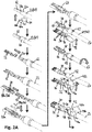
- Figs. 2A to 2C depict an assembly instruction for the connector 10 of Fig. 1 .
- the inner crimp ferrule 60 is crimped onto the cable 22.
- the inner crimp ferrule 60 has a first portion 60a that is crimped around portion 22a of the cable 22 where a protection layer 61 is the outermost layer of the cable 22.
- the inner crimp ferrule 60 further has a second part which is formed around a portion 22b of the cable 22 where a shield layer 62 of the cable 22 is the outermost layer of the cable 22, i.e. where the protection layer 61 has been removed.
- the shield layer 62 is folded backwards over the inner crimp ferrule 60. Additionally, end sections 22c of the cable 22 are stripped so that the conductors or wires 20 of the cable 22 are not surrounded by insulation material anymore.
- the inner signal contacts 12 are connected to the stripped sections 22c of the wires 20. While the inner signal contacts 12 are connected via crimping in the shown embodiment, the electrical connection between the inner signal contacts 12 and the wires 20 can be improved if the connection is established by welding, in particular laser welding. To improve cycle time of this connecting step, the two inner signal contacts 12 can be connected to the stripped sections of the wires 20 simultaneously.
- the first part 28a of the insulating element 28 is put on the inner signal contacts 12 from the axial direction 14 so that the inner signal contacts 12 are assimilated in axial channels 64 of the first part 28a of the insulating element 28. Then, the second part 28b of the insulating element 28 is clicked on the first part 28a of the insulating element 28 from a radial direction. Thereby, the inner signal contacts 12 are axially fixed to the insulating element 28.
- the first shielding part 30 is placed onto a section extending from a distal end of the insulating element 28 to a section of the cable 22 where the shield layer 62 is folded backwards onto the protection layer 61 of the cable 22.
- the first shielding part 30 comprises two connecting wings 66 which are bent around the insulating element 28 in order to radially fixate the first shielding part 30 onto the insulating element 28.
- blocking elements 68 are formed on an outer surface of the insulating element 28. The blocking elements 68 engage with the connecting wings 66 in order to limit or prevent axial movement of the first shielding part 30.
- the shielding wings 46 are placed onto the cable 22 and bent almost all the way around the wires 20 and their respective insulation (cf. Fig. 6B ).
- the cover 42 comes into contact with the back-folded portion of the shield layer 62.
- the second shielding part 32 is attached to the assembly from an opposite radial side.
- the second shielding part 32 comprises connecting wings 70 which are bent around the first shielding part 30 to radially fixate the second shielding part 32 onto the first shielding part 30.
- a groove 72 extending perpendicular to the axial direction 14 is formed on the outer surface of the first shielding part 30 into which the connecting wings 70 of the second shielding part 32 are placed. Thereby, the second shielding part 32 is axially fixated onto the first shielding part 30. Additionally, a rather smooth outer surface of the shielding contact 34 is generated.
- the second shielding part 32 further comprises the wings 48 which are positioned in a corresponding axial section to the section of the wings 46.
- EMC-labyrinth i.e. a shield where interference signals run dead
- the second wings 48 same as the wings 46, are bent so that they surround the respective section of the cable 22 almost completely. Since the first and second shielding parts 30, 32 are placed around the cable from opposite sides, gaps 74, 75 (cf. Fig. 6B ) which are present at least in an axial section between peripheral end sections 46a, 46b, 48a, 48b of the wings 46, 48 are positioned on opposite sides of the cable 22.
- the second shielding part 32 also comprises the crimping portion 44 which is arranged in a corresponding axial section to the section of the cover 42 of the first shielding part 30.
- the crimping portion 44 comprises two crimp wings 44a, 44b which are bent around the cable 22 and the cover 42 of the first shielding part 30.
- the crimp wings 44a, 44b define corresponding peripheral ends 45a, 45b.
- the cover 42 is helpful to hold the shield layer 62, usually a braid, down while the crimp wings 44a, 44b are bent around the cable 22. It has been found that providing such a cover 42 improves production quality and robustness against cable abuse.
- the cover 54 is placed around the first and second shielding parts 30, 32 to secure the connection between the first and second shielding parts 30, 32.
- the cover 54 comprises two parts: the first cover part 56 and the second cover part 58.
- the first cover part 56 is positioned around portions of the first and second shielding parts 30, 32 from a radial direction different from the directions from which the first and second shielding parts 30, 32 are placed onto the assembly.
- the second cover part 58 is also positioned around portions of the first and second shielding parts 30, 32 from a radial direction different from the directions from which the first and second shielding parts 30, 32 and the first cover part 56 are placed onto the assembly.
- first and second cover parts 56, 58 are placed onto the first and second shielding parts 30, 32 from opposite radial directions.
- connecting means are provided at the first and second cover parts 56, 58, in particular snap fit engagement means.
- the connector 10 is inserted into a connector housing 78, in particular a female connector housing.
- the shown connector housing 78 is compliant to the standards set for the above mentioned H-MTD® system.
- the connector housing 78 comprises terminal position assurance (TPA) 80 in form of a pusher. The pusher 80 is pushed radially into the connector housing 78 to axially connect the connector housing 78 to the connector 10.
- TPA terminal position assurance
- Fig. 3 depicts an assembly instruction for a connector 10 according to a second embodiment.
- the inner signal contacts 12 are axially inserted into the insulating element 28.
- the insulating element 28 is formed as a single integral part.
- two axially extending passage openings 64 are formed which receive the inner signal contacts 12.
- the inner signal contacts 12 can be axially fixated on the insulating element 28 by a snap-lock connection as shown in Fig. 14 .
- the inner signal contacts 12 can alternatively or additionally be axially fixated on the insulating element 28 by hooks 103 ( Fig 12A ) or dimples formed on the inner signal contacts 12 and interfering with the insulating element 28.
- An insertion depth controlled by an assembly machine can be used to make sure that both inner signal contacts 12 are inserted the same distance into the insulating element 28. After the inner signal contacts 12 are pre-assembled with the insulating element 28, the inner signal contacts 12 are connected to the wires 20 by laser or resistance welding.
- a first shielding part 30 is placed around the insulating element 28 and the cable 22.
- the shielding part 30 placed first around the insulating element 28 has the crimp wings 44a, 44b.
- a second difference between the assembly processes is that the first shielding part 30 in Fig. 3 has an insulating layer 82a which was molded over a section of the first shielding part 30.
- the insulating layer 82a comprises a rib 84 which is placed between the two wires 20 of the cable 22 to establish a further insulation between the wires 20.
- a second shielding part 32 is also placed around the insulating element 28 and the cable 22.
- the second shielding part 32 also has as an insulating layer 82b which was molded over a section of the second shielding part 32.
- the insulating layers 82a and 82b together form an insulating layer 82 formed on the inside an the outside of the first and second shielding parts 30, 32.
- This insulating layer 82 allows forming multiple quality control elements 86 which can be used to evaluate whether the first and second shielding parts 30, 32 are joined together correctly and whether the wires 20 and/or the insulating element 28 are located in the right place.
- the crimp wings 44a, 44b of the first shielding part 30 are crimped around the cover 42 of the second shielding part 32 and the first and second shielding parts 30, 32 are connected to each other via laser welding.
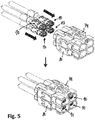
- Figs. 4 and 5 depict options how to group multiple connectors 10 together.
- a connector collector housing 78 is shown that is connected to two female connectors 10.
- the cover parts 56, 58 or the insulating layers 82a and 82b ( Fig. 3 ), in particular their rear edges 77, can be used to securely lock the connectors 10 within the collector housing 78. In particular, they can be used to enably a primary and secondary lock of the connector 10 in the housing 78.
- a connector collector housing 78 capable of taking up four connectors 10 arranged in two lines and 2 rows is shown. This connector housing 78 allows connecting four cables 22 to mating cables at once.
- Figs. 6A and 6B depict a section of the connector 10 where wings 46, 48 of the first and second shielding parts 30, 32 are located.
- Fig. 6B shows a cross sectional view of the above mentioned section along the dashed line shown in Fig. 6A .
- two insulated conductors or wires 20 extend generally parallel to each other.
- the inner shield 50 is formed by the wings 46 of the first shielding part 30.
- the inner shield 50 almost completely surrounds the wires 20. Only a small gap 74 is left between the peripheral ends 46a, 46b. As can be seen from Fig. 6B , the gap 74 is smaller than a distance between outer surfaces of the conductors 20.
- an embossment 88 is formed so that the inner shield 50 extends into a free space between insulations of the two wires 20.
- the inner shield 50 therefore has a cross sectional shape similar to two scuba tanks or scuba glasses.
- the outer shield 52 is formed around the inner shield 50.
- the outer shield 52 has a similar general shape as the inner shield 50 but it has a larger diameter. Therefore, a second gap 75 is present between the peripheral ends 48a, 48b of the wings 48.
- the gap 75 between the peripheral ends 48a, 48b of the wings 48 is located at the angular position of the embossment 88 formed in the wing 46.
- the outer shield 52 also forms an embossment 89 which is located at the angular position of the gap 74 of the inner shield 50.
- the two shields 50, 52 create an "EMC-labyrinth" which provides improved shielding to the wires 20 against interfering signals.
- the gaps 74 and 75 are closed by the embossment 89 being in contact with the wings 46a and 46b.
- the wings 46a and 46b can be pushed against the embossment 89 by mounting the cover part 54 onto the first and second outer shielding contacts 30, 32.
- the embossment can be larger and/or higher at the axial beginning and the axial end in comparison to a middle section of the embossment. As such, a return current which flows on the outer shielding contact 34 does not need to make any detours and can remain running in parallel and close by the signal currents.
- Figs. 7A and 7B depict a section of the connector 10 where the first and second shielding parts 30, 32 are connected to the cable 22.
- two insulated wires 20 are shown.
- a foil 91 is arranged.
- the shield layer 62 of the cable 22 is arranged around the foil 91.
- the shield layer 62 of the cable 22 is formed as a braid.
- the protection layer 61 of the cable 22 usually forming the outmost layer of the cable 22 is arranged.
- the inner crimp ferrule 60 is attached to the outer surface of the protection layer 61.
- the shield layer 62 is folded backwards onto the inner crimp ferrule 60.
- the cover 42 of the first shielding part 30 is placed on top of the back-folded shield layer 62.
- the crimping portion 44 of the second shielding part 32 is placed on top of the cover 42 and the back-folded shield layer 62.
- the peripheral ends 45a, 45b of the crimp wings 44a, 44b of the second shielding part 30 are placed in an angular section where the cover 42 covers the shield layer 62.
- the shield layer 62 is protected from the peripheral ends 45a, 45b of the crimp wings 44a, 44b.
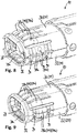
- Fig. 8 depicts a distal end of the connector 10 according to a first embodiment.
- the shielding contact 34 is formed from the first and second shielding parts 30, 32.
- a distal end portion of the first and second shielding parts 30, 32 is mirror symmetrical so that the opposite side not shown in Fig. 8 of said distal end portion looks the same.
- the shielding contact is oval and thus has two longer sides and two shorter sides.
- a first group 38a of shielding contacts 38 are positioned which generally extend in the axial direction 14 and are elastically deformable in a radial direction.
- a second group 38b of shielding contacts 38 is formed on the shielding contact 34.
- the second group 38b of shielding contacts 38 consists of four shielding contacts 38b which each comprise two U-shaped portions 90.
- the U-shaped portions 90 are design so that the bottom part of each U-shaped portion 90 is closest to the insulating element 28 arranged at an inside of the shielding contact 34.
- the second group 38b of shielding contacts 38 is connected via a distal ring element 92.
- the distal ring element 92 is formed of two ring segments, each connecting two second group shielding contacts 38b of the respective first and second shielding part 30, 32.
- the distal ring element 92 holds the first group 38a of shielding contacts 38 in a pre-loaded position, i.e. the first group 38a of shielding contacts 38 push against an inner side of the distal ring element 92.
- each of the shielding contacts 38 has a defined contact point 94 which is defined by an elevation at the outer surface of the respective contact 38.
- some of the contact points 94 are axially spaced apart from other contact points 94.
- contact points 94a of the first group 38a of shielding contacts 38 are axially distanced from contact points 94b of the second group 38b of shielding contacts 38.
- the first group 38a of shielding contacts 38 has two separate types of shielding contacts 38a, wherein the first type of shielding contacts 38a, the two inner shielding contacts, has contact points 94a which are axially distanced from contact points of the second type of shielding contacts 38a, the two outer shielding contacts.
- Fig. 9 depicts a distal end of the connector 10 according to a second embodiment.
- the connector 10 has a first group 38a of shielding contacts 38 which consists of five upper contacts 38a and five lower contacts 38a.
- the distal ring element 92 of Fig. 9 is a closed ring element, i.e. the ring segments are connected to each other, e.g. by laser welding.
- the plurality of shielding contacts 38a, 38b are arranged symmetrically and generally equally distanced from each other.
- the plurality of shielding contacts 38a, 38b is integrally formed with their respective first or second shielding part 30, 32.
- the segments of the distal ring element 92 are also integrally formed with their respective first or second shielding part 30, 32.
- the first and second shielding parts 30, 32 can be made from sheet-metal and can be designed as a stamped/bent part.
- Figs. 10A and 10B depict an embodiment, wherein an outer crimping tube 96 is put on the crimping portion 44.
- the outer crimping tube 96 in comparison to the cross-sectional view shown in fig 7B , in the cross-sectional view of Fig. 10B , there is additionally shown the outer crimping tube 96.
- the outer crimping tube 96 as is shown in Fig. 10A , can be put on the crimping portion 44 from a cable-side instead of a connector-side.
- a shrink tube (not shown), i.e. an elastic tube which shrinks when heat is being applied to it, can be used to cover the crimping portion 44.
- Figs. 11A and 11B depict the inner signal contacts 12 according to a first embodiment.
- the two elongated inner signal contacts 12 generally extend parallel to one another.
- Each inner signal contact 12 has a first connection portion 16 for connecting the signal contact 12 to a mating signal contact and a second connection portion 18 for connecting the signal contacts 12 to a respective wire 20 of a cable 22.
- Each of the first connection portions 16 is formed as a tube having a first center axis 98.
- the first connection portions 16 can comprise a solid pin welded into a stamped and rolled rear section to form male signal contacts.
- Each of the second connection portions 18 define a second center axis 100 where a center axis of the cable is placed at.
- a distance A between the center axes 98 of the first connection portions 16 is larger than a distance B between the center axes 100 of the second connection portions 18.
- a distance between the center axes of the first connection portions can be smaller than a distance between the center axes of the second connection portions.
- the inner signal contacts 12 are formed so that a pitch translation is generated.
- Each of the two inner signal contacts 12 are formed so that the first center axis 98 is spaced apart in parallel from the second center axis 100.
- sections 102 of the inner signal contacts 12 extend into a direction oblique to the axial direction 14.
- the sections 102 can be formed by flat sheet metal or by a tube-shaped cross section.
- Fig. 11B depicts the inner signal contacts 12 inserted in the insulating element 28a of Fig. 2A .
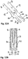
- Figs. 12A and 12B depict inner signal contacts 12 according to a second embodiment.
- the inner signal contacts 12 differ from the inner signal contacts 12 of figs. 11A and 11B in that hooks 103 are formed at side surfaces of the flat sections 102.
- the inner signal contacts 12 can be inserted into an insulating element 28 as shown in Fig. 12B and Fig. 3 and can be axially fixated by the hooks 103.
- welding openings 26 are formed at an upper side so that the inner signal contacts 12 can be easily connected to the wires 20 of the cable 22 via welding, e.g. laser or resistance welding.
- crimping wings 24 can be formed at the second connection portions 18 so that the inner signal contacts 12 can be crimped onto the wires 20 of the cable 22.
- Figs. 13A and 13B depict the insulating element 28 according to another embodiment.
- the insulating element 28 is manufactured by overmolding the inner signal contacts 12. In order to make sure that the mold does not enter into the tubular first and second connection portions 16, 18, the tubular portions are sealed during the molding process. Similarly, the welding openings 26 or crimping wings 24 are not overmolded to be able to connect the inner signal contacts 12 to wires 20 of the cable 22 later on.
- the insulating element 28 comprises a locking element 104 in form of an elastically deformable element which creates a snap fit connection between the inner signal contacts 12 and the insulating element 28 in the axial direction 14.
- the locking element 104 has a first locking surface 106 which comes into contact with a second locking surface 108 of the inner signal contacts 12 by snapping back from a deformed position into a neutral position in a radial direction.
- This embodiment allows manufacturing the insulating element 28 as a 1-piece part, e.g. by molding.
- the locking element 104 is a solid part 28b which is not formed integrally with the remaining insulating element 28 - as is shown in Fig. 14 -, but instead, the insulating element 28 is made out of two separate parts 28a, 28b as is shown in Fig. 1 .
- the second part 28b of the insulating element 28 functions as the locking element 104 and thus comprises the first locking surface 106 which comes into contact with the second locking surface 108 of the inner signal contacts 12, in particular when the connector 10 is plugged into a mating connector. Once the outer shielding contact 34 is assembled, the locking element 104 is blocked in position.
- the inner signal contacts 12 can be formed integrally from sheet metal. In order to manufacture the inner signal contacts 12 in a cost-efficient manner, the inner signal contacts 12 can be designed as stamped/bent parts.
- signal integrity can be improved by having less differential impedance mismatch, less long regions of differential impedance mismatch and less skew.
Landscapes
- Details Of Connecting Devices For Male And Female Coupling (AREA)
Abstract
Description
- The present disclosure relates to a connector for automotive applications and an assembly comprising such a connector. Preferably, the present disclosure relates to a connector for automotive multi GHz applications and an assembly comprising such a connector. In particular, the disclosure relates to an H-MTD® (High Speed Modular Twisted-Pair-Data) connector and an assembly comprising such an H-MTD® connector.
- The so called H-MTD® system is produced by a company called "Rosenberger Hochfrequenztechnik GmbH & Co. KG". Connectors of said system are meant to allow data transmission up to 15 GHz or 20 Gbps while having a small package size. Applications for the H-MTD® system are 4K camera systems, autonomous driving, radar, lidar, high-resolution displays and rear seat entertainment.
- There is a need to improve assembling of the connector while at the same time further improve quality of the connector.
- The present disclosure provides a connector for automotive applications comprising at least one inner signal contact and an outer shielding contact. The outer contact comprises a crimping portion including a first crimp wing and a second crimp wing bendable towards each other to attach the connector to a cable such that ends of the first crimp wing and the second crimp wing extend towards each other when the connector is attached to the cable. The connector further comprises a cover for covering a braid and/or a protective layer of the cable arranged underneath the ends of the crimp wings when the connector is attached to the cable.
- The inventors have come to the conclusion that the product quality of the connector is improved by providing a cover that separates a cable shield, e.g. a braid, and/or a protective layer from the ends of the crimp wings of the connector. The cover effectively reduces the risk of damaging the cable shield or the protective layer when the crimp wings are formed around the cable shield.
- Embodiments are given in the subclaims, the description and the drawings.
- To improve maximum data rate, the connector can comprise at least two inner signal contacts.
- According to an embodiment, the ends of the first and second crimp wings extend in a generally peripheral direction when the connector is attached to the cable. The first and second crimp wings can be formed around the cover so that the ends of the first and second crimp wings extend along a surface of the cover.
- In order to form a shield for wires of the cable, the cover can be made out of metal, in particular sheet metal.
- According to an embodiment, the outer shielding contact comprises a first outer contact part and a second outer contact part. In this case, the first outer contact part can form the first and second crimp wings and the second outer contact part can form the cover. This simplifies manufacturing and assembling of the connector.
- According to a further embodiment, the first outer contact part and/or the second outer contact part is/are generally formed as half shells. The half shells can have a generally U-shaped cross section and can be joined together to form a generally oval outer shielding contact.
- In order to manufacture the outer shielding contact cost-efficiently, the first outer contact part and/or the second outer contact part can be made from sheet metal. In particular, the first outer contact part and/or the second outer contact part can each be integrally formed from a single piece of sheet metal.
- According to an embodiment, the first crimp wing defines a first peripheral front face and the second crimp wing defines a second peripheral front face corresponding to the first peripheral front face. In other words, the first peripheral front face and the second peripheral front face can match like matching puzzle pieces.
- To improve the crimping connection, the first peripheral front face can comprise at least one step portion and the second peripheral front face can comprise at least one corresponding step portion. In other words, the first crimp wing can form two front faces distanced from each other axially and along a circumferential direction. Similarly, the second crimp wing can form two front faces distanced from each other axially and along a circumferential direction.
- According to an embodiment, the cover is formed as an arc. In particular, the cover may not extend all around the cable but can be arranged only on one side of the cable. This simplifies manufacturing and assembling, especially if the outer shielding contact is made from two separate parts.
- According to a further embodiment, the first crimp wing and the second crimp wing are configured to touch each other when the connector is attached to the cable. In particular, the first and second crimp wings can be configured to touch each other with their respective peripheral front faces, when the connector is attached to the cable. This has the advantage that a rather smooth outer surface is created in the crimping portion.
- In order to secure the connection between the connector and the cable, the first crimp wing and the second crimp wing can be welded together when the connector is attached to the cable. A connection by laser welding has been shown good results in terms of quality of the connection.
- In order to simplify manufacturing and especially to provide all welding locations necessary to manufacture the connector on two opposite sides of the connector, the first crimp wing and/or the second crimp wing can be provided with openings (not shown in the figures) for welding the first crimp wing and/or the second crimp wing, in particular by laser welding, to the cover.
- According to an embodiment, the outer contact forms a plurality of spring contacts arranged around the at least one inner signal contact in a region of the connector opposite from the crimping portion. The spring contacts can be formed integral with the remaining outer contact, e.g. out of sheet metal.
- According to another aspect, an assembly is provided comprising a connector according to at least one of the aforementioned or later mentioned embodiments and a cable attached to the crimping portion of the connector, wherein the cable is a shielded-twisted-pair cable or a shielded-parallel-pair cable. Such cables can be used to transmit large amounts of data in a shielded manner.
- The cable can comprise two inner wires and an outer shield. The cover can be in direct contact with the outer shield of the cable. Furthermore, parts of the crimp wings can also be in direct contact with the outer shield of the cable. This allows good electrical contact between the shield of the cable and the outer shielding contact of the connector.
- The cover is particularly useful if the shield of the cable is formed as a braid since parts of such a braid can easily extend through openings generated in the crimping portion by production inaccuracies.
- In order to further improve the visual appearance of the crimping portion, an outer crimping tube or a shrink tube can be arranged around the crimping portion.
- Exemplary embodiments and functions of the present disclosure are described herein in conjunction with the following drawings, showing:
- Fig. 1
- an exploded view of a connector according to the claimed subject matter;
- Fig. 2A to 2C
- an assembly instruction for the connector of
Fig. 1 ; - Fig. 3
- an assembly instruction for a second connector according to the claimed subject matter;
- Fig. 4
- a 2-Port connector with two of the connectors of
Fig. 1 ; - Fig. 5
- a 4-Port 2-Row connector with four of the connectors of
Fig. 1 ; - Fig. 6A
- a perspective view of the connector of
Fig. 1 from a proximal side; - Fig. 6B
- a cross-sectional view of the connector of
Fig. 1 along the dashed line ofFig. 6A ; - Fig. 7A
- a perspective view of the connector of
Fig. 1 from a proximal side; - Fig. 7B
- a cross-sectional view of the connector of
Fig. 1 along the dashed line ofFig. 7A ; - Fig. 8
- a perspective view of a distal end of a connector according to a first embodiment;
- Fig. 9
- a perspective view of a distal end of a connector according to a second embodiment;
- Fig. 10A
- a perspective view of a proximal end of a connector wherein a crimp section of the connector is covered by an outer crimping tube;
- Fig. 10B
- a cross-sectional view of the assembly of
Fig. 10A along the dashed line ofFig. 10A ; - Fig. 11A
- a perspective view of inner signal contacts according to a first embodiment;
- Fig. 11B
- a perspective view of the inner signal contacts of
Fig. 11A embedded in an insulating element; - Fig. 12A
- a perspective view of inner signal contacts according to a second embodiment;
- Fig. 12B
- a sectional top view of the inner signal contacts of
Fig. 12A surrounded by a respective insulating element; - Fig. 13A
- a perspective view of overmolded signal contacts;
- Fig. 13B
- a sectional top view of the overmolded signal contacts of
Fig. 13A placed in an outer shielding part; - Fig. 14
- a sectional side view of a signal contact embedded in an insulating element according to a first embodiment;
- Fig. 15
- a sectional side view of a signal contact embedded in an insulating element according to a second embodiment.
-
Fig. 1 depicts an exploded view of aconnector 10, in particular a female connector, comprising two elongatedinner signal contacts 12 arranged generally parallel to each other along a plug oraxial direction 14 of theconnector 10. Thesignal contacts 12 have afirst connection portion 16 for connecting theconnector 10 to a mating connector, in particular a mating male connector, and asecond connection portion 18 for connecting thesignal contacts 12 to respective conductors orwires 20 of acable 22. Thesecond connection portion 18, as depicted by the two alternatives shown inFig. 1 , can be formed as a crimpingportion 18a having two crimping wings 24 or can be formed as awelding portion 18b having awelding opening 26. Thewelding opening 26 can be used to connect thesignal contacts 12 to respective conductors orwires 20 of thecable 22 via laser welding. Alternatively, resistance welding can be used to connect thesignal contacts 12 to respective conductors orwires 20 of thecable 22. - Around the
inner signal contacts 12 an insulatingelement 28 which can be called di-electric housing is arranged. In the embodiment shown inFig. 1 , the insulatingelement 28 is made out of twoseparate parts second parts element 28 are attachable to each other by a click-on connection, i.e. a snap fit engagement. Thesecond part 28b fulfills the task of locking thesignal contacts 12 in an axial direction so that theinner signal contacts 12 remain in their axial position when theconnector 10 is connected to a mating connector. A more detailed explanation of this feature will be given in regard tofigs. 14 and 15 . - The
connector 10 further comprises afirst shielding part 30 and asecond shielding part 32 both formed as half shells which together form anouter shielding contact 34. Theouter shielding contact 34 surrounds theinner signal contacts 12 and the insulatingelement 28 to provide a shield against interfering signals. However, theouter shielding contact 34 can also be used as an electrical conductor to transport electric power. At adistal end 36 of theconnector 10, theouter shielding contact 34 comprises multiple shieldingcontacts 38 which are discussed in more detail regardingfigs. 8 and 9 . At aproximal end 40 of theconnector 10, the first shieldingpart 30 forms acover 42 which is discussed in more detail in regard toFig. 7B . Thesecond shielding part 32 forms a crimpingportion 44 at theproximal end 40 of theconnector 10 to mechanically and electrically connect theouter shielding contact 34 to thecable 22. Furthermore, the first andsecond shielding parts wings inner shield 50 and anouter shield 52 overlapping theinner shield 50. A more detailed description of the inner andouter shield figs. 6A and 6B . - In order to better secure the connection between the first shielding
part 30 and thesecond shielding part 32, acover 54 comprising afirst cover part 56 and asecond cover part 58 are placed around the first andsecond shielding parts second cover parts part 30 and thesecond shielding part 32. Furthermore, theconnector 10 comprises aninner crimp ferrule 60 which is placed around thecable 22. -
Figs. 2A to 2C depict an assembly instruction for theconnector 10 ofFig. 1 . In a first step, theinner crimp ferrule 60 is crimped onto thecable 22. Theinner crimp ferrule 60 has a first portion 60a that is crimped aroundportion 22a of thecable 22 where aprotection layer 61 is the outermost layer of thecable 22. Theinner crimp ferrule 60 further has a second part which is formed around a portion 22b of thecable 22 where ashield layer 62 of thecable 22 is the outermost layer of thecable 22, i.e. where theprotection layer 61 has been removed. After theinner crimp ferrule 60 is connected to thecable 22, theshield layer 62 is folded backwards over theinner crimp ferrule 60. Additionally,end sections 22c of thecable 22 are stripped so that the conductors orwires 20 of thecable 22 are not surrounded by insulation material anymore. In the next step, theinner signal contacts 12 are connected to the strippedsections 22c of thewires 20. While theinner signal contacts 12 are connected via crimping in the shown embodiment, the electrical connection between theinner signal contacts 12 and thewires 20 can be improved if the connection is established by welding, in particular laser welding. To improve cycle time of this connecting step, the twoinner signal contacts 12 can be connected to the stripped sections of thewires 20 simultaneously. - After the
inner signal contacts 12 are attached to thewires 20, thefirst part 28a of the insulatingelement 28 is put on theinner signal contacts 12 from theaxial direction 14 so that theinner signal contacts 12 are assimilated inaxial channels 64 of thefirst part 28a of the insulatingelement 28. Then, thesecond part 28b of the insulatingelement 28 is clicked on thefirst part 28a of the insulatingelement 28 from a radial direction. Thereby, theinner signal contacts 12 are axially fixed to the insulatingelement 28. - After the insulating
element 28 is connected to theinner signal contacts 12, the first shieldingpart 30 is placed onto a section extending from a distal end of the insulatingelement 28 to a section of thecable 22 where theshield layer 62 is folded backwards onto theprotection layer 61 of thecable 22. In order to connect the first shieldingpart 30 to the insulatingelement 28, the first shieldingpart 30 comprises two connectingwings 66 which are bent around the insulatingelement 28 in order to radially fixate the first shieldingpart 30 onto the insulatingelement 28. For axial fixation of the first shieldingpart 30, blockingelements 68 are formed on an outer surface of the insulatingelement 28. The blockingelements 68 engage with the connectingwings 66 in order to limit or prevent axial movement of the first shieldingpart 30. Furthermore, in a section of thecable 22 right before the distance between thewires 20 is increased, the shieldingwings 46 are placed onto thecable 22 and bent almost all the way around thewires 20 and their respective insulation (cf.Fig. 6B ). By placing the first shieldingpart 30 onto the insulatingelement 28 and thecable 22, thecover 42 comes into contact with the back-folded portion of theshield layer 62. - For simplifying explanation of the method of assembling, the assembly is turned in the figures. However, this is not a necessary step in production.
- After the first shielding
part 30 is securely fixed to the insulatingelement 28 and thecable 22, thesecond shielding part 32 is attached to the assembly from an opposite radial side. Thesecond shielding part 32 comprises connectingwings 70 which are bent around the first shieldingpart 30 to radially fixate thesecond shielding part 32 onto the first shieldingpart 30. Agroove 72 extending perpendicular to theaxial direction 14 is formed on the outer surface of the first shieldingpart 30 into which the connectingwings 70 of thesecond shielding part 32 are placed. Thereby, thesecond shielding part 32 is axially fixated onto the first shieldingpart 30. Additionally, a rather smooth outer surface of the shieldingcontact 34 is generated. - The
second shielding part 32 further comprises thewings 48 which are positioned in a corresponding axial section to the section of thewings 46. In order to establish a so called "EMC-labyrinth", i.e. a shield where interference signals run dead, thesecond wings 48, same as thewings 46, are bent so that they surround the respective section of thecable 22 almost completely. Since the first andsecond shielding parts gaps 74, 75 (cf.Fig. 6B ) which are present at least in an axial section betweenperipheral end sections 46a, 46b, 48a, 48b of thewings cable 22. - The
second shielding part 32 also comprises the crimpingportion 44 which is arranged in a corresponding axial section to the section of thecover 42 of the first shieldingpart 30. The crimpingportion 44 comprises twocrimp wings cable 22 and thecover 42 of the first shieldingpart 30. Thecrimp wings cover 42 is helpful to hold theshield layer 62, usually a braid, down while thecrimp wings cable 22. It has been found that providing such acover 42 improves production quality and robustness against cable abuse. - After the
second shielding part 32 is fixated on the first shieldingpart 30, thecover 54 is placed around the first andsecond shielding parts second shielding parts cover 54, as mentioned before, comprises two parts: thefirst cover part 56 and thesecond cover part 58. Thefirst cover part 56 is positioned around portions of the first andsecond shielding parts second shielding parts second cover part 58 is also positioned around portions of the first andsecond shielding parts second shielding parts first cover part 56 are placed onto the assembly. In particular, the first andsecond cover parts second shielding parts second cover parts second cover parts - After the first and
second cover parts second shielding parts connector 10 is inserted into aconnector housing 78, in particular a female connector housing. The shownconnector housing 78 is compliant to the standards set for the above mentioned H-MTD® system. In order to attach theconnector housing 78 to theconnector 10, theconnector housing 78 comprises terminal position assurance (TPA) 80 in form of a pusher. Thepusher 80 is pushed radially into theconnector housing 78 to axially connect theconnector housing 78 to theconnector 10. -
Fig. 3 depicts an assembly instruction for aconnector 10 according to a second embodiment. According to the assembly method, theinner signal contacts 12 are axially inserted into the insulatingelement 28. In this example, the insulatingelement 28 is formed as a single integral part. In the insulatingelement 28, two axially extendingpassage openings 64 are formed which receive theinner signal contacts 12. Theinner signal contacts 12 can be axially fixated on the insulatingelement 28 by a snap-lock connection as shown inFig. 14 . Theinner signal contacts 12 can alternatively or additionally be axially fixated on the insulatingelement 28 by hooks 103 (Fig 12A ) or dimples formed on theinner signal contacts 12 and interfering with the insulatingelement 28. An insertion depth controlled by an assembly machine can be used to make sure that bothinner signal contacts 12 are inserted the same distance into the insulatingelement 28. After theinner signal contacts 12 are pre-assembled with the insulatingelement 28, theinner signal contacts 12 are connected to thewires 20 by laser or resistance welding. - After the
inner signal contacts 12 are connected to thewires 20, afirst shielding part 30 is placed around the insulatingelement 28 and thecable 22. However, compared to the assembly process described regardingfigs. 2A to 2C , the shieldingpart 30 placed first around the insulatingelement 28 has thecrimp wings part 30 inFig. 3 has an insulatinglayer 82a which was molded over a section of the first shieldingpart 30. The insulatinglayer 82a comprises arib 84 which is placed between the twowires 20 of thecable 22 to establish a further insulation between thewires 20. After the first shieldingpart 30 is placed around the insulatingelement 28 and thecable 22, asecond shielding part 32 is also placed around the insulatingelement 28 and thecable 22. Thesecond shielding part 32 also has as an insulating layer 82b which was molded over a section of thesecond shielding part 32. As can be seen inFig. 3 , the insulatinglayers 82a and 82b together form an insulating layer 82 formed on the inside an the outside of the first andsecond shielding parts quality control elements 86 which can be used to evaluate whether the first andsecond shielding parts wires 20 and/or the insulatingelement 28 are located in the right place. - After placing the
second shielding part 32 onto the first shieldingpart 30, thecrimp wings part 30 are crimped around thecover 42 of thesecond shielding part 32 and the first andsecond shielding parts -
Figs. 4 and5 depict options how to groupmultiple connectors 10 together. InFig. 4 aconnector collector housing 78 is shown that is connected to twofemale connectors 10. Thecover parts layers 82a and 82b (Fig. 3 ), in particular theirrear edges 77, can be used to securely lock theconnectors 10 within thecollector housing 78. In particular, they can be used to enably a primary and secondary lock of theconnector 10 in thehousing 78. Using such aconnector collector housing 78 allows faster assembly of an electrical wiring harness of a car. InFig. 5 , aconnector collector housing 78 capable of taking up fourconnectors 10 arranged in two lines and 2 rows is shown. Thisconnector housing 78 allows connecting fourcables 22 to mating cables at once. -
Figs. 6A and 6B depict a section of theconnector 10 wherewings second shielding parts Fig. 6B shows a cross sectional view of the above mentioned section along the dashed line shown inFig. 6A . In an inner region of theconnector 10, two insulated conductors orwires 20 extend generally parallel to each other. Around thewires 20, theinner shield 50 is formed by thewings 46 of the first shieldingpart 30. Theinner shield 50 almost completely surrounds thewires 20. Only asmall gap 74 is left between theperipheral ends 46a, 46b. As can be seen fromFig. 6B , thegap 74 is smaller than a distance between outer surfaces of theconductors 20. At an opposite side of thegap 74, anembossment 88 is formed so that theinner shield 50 extends into a free space between insulations of the twowires 20. One could say that theinner shield 50 therefore has a cross sectional shape similar to two scuba tanks or scuba glasses. Around theinner shield 50, theouter shield 52 is formed. Theouter shield 52 has a similar general shape as theinner shield 50 but it has a larger diameter. Therefore, asecond gap 75 is present between the peripheral ends 48a, 48b of thewings 48. Thegap 75 between the peripheral ends 48a, 48b of thewings 48 is located at the angular position of theembossment 88 formed in thewing 46. On the other hand, theouter shield 52 also forms anembossment 89 which is located at the angular position of thegap 74 of theinner shield 50. The twoshields wires 20 against interfering signals. - At an axial beginning and an axial end of the section where
wings second shielding parts gaps embossment 89 being in contact with thewings 46a and 46b. Thewings 46a and 46b can be pushed against theembossment 89 by mounting thecover part 54 onto the first and second outer shieldingcontacts embossment 89 is in contact with thewings 46a and 46b only at the axial beginning and the axial end of the tunnel in tunnel section, the embossment can be larger and/or higher at the axial beginning and the axial end in comparison to a middle section of the embossment. As such, a return current which flows on theouter shielding contact 34 does not need to make any detours and can remain running in parallel and close by the signal currents. -
Figs. 7A and 7B depict a section of theconnector 10 where the first andsecond shielding parts cable 22. In a center of the cross-section depicted inFig. 7B , twoinsulated wires 20 are shown. Around thewires 20, afoil 91 is arranged. Then, theshield layer 62 of thecable 22 is arranged around thefoil 91. Theshield layer 62 of thecable 22 is formed as a braid. Around theshield layer 62, theprotection layer 61 of thecable 22 usually forming the outmost layer of thecable 22 is arranged. In the section shown inFig. 7B , theinner crimp ferrule 60 is attached to the outer surface of theprotection layer 61. Theshield layer 62 is folded backwards onto theinner crimp ferrule 60. On top of the back-foldedshield layer 62, in a top section of the cable, thecover 42 of the first shieldingpart 30 is placed. On top of thecover 42 and the back-foldedshield layer 62, the crimpingportion 44 of thesecond shielding part 32 is placed. As can be seen fromFig. 7B , the peripheral ends 45a, 45b of thecrimp wings second shielding part 30 are placed in an angular section where thecover 42 covers theshield layer 62. Hence, theshield layer 62 is protected from the peripheral ends 45a, 45b of thecrimp wings -
Fig. 8 depicts a distal end of theconnector 10 according to a first embodiment. The shieldingcontact 34 is formed from the first andsecond shielding parts second shielding parts Fig. 8 of said distal end portion looks the same. The shielding contact is oval and thus has two longer sides and two shorter sides. At the longer sides, afirst group 38a of shieldingcontacts 38 are positioned which generally extend in theaxial direction 14 and are elastically deformable in a radial direction. At the shorter side of theconnector 10, a second group 38b of shieldingcontacts 38 is formed on the shieldingcontact 34. The second group 38b of shieldingcontacts 38 consists of four shielding contacts 38b which each comprise twoU-shaped portions 90. TheU-shaped portions 90 are design so that the bottom part of eachU-shaped portion 90 is closest to the insulatingelement 28 arranged at an inside of the shieldingcontact 34. The second group 38b of shieldingcontacts 38 is connected via a distal ring element 92. The distal ring element 92 is formed of two ring segments, each connecting two second group shielding contacts 38b of the respective first and second shieldingpart first group 38a of shieldingcontacts 38 in a pre-loaded position, i.e. thefirst group 38a of shieldingcontacts 38 push against an inner side of the distal ring element 92. This allows plugging theconnecter 10 into a mating connector needing less force. The distal ring element 92 also prevents that ends of theshield contacts 38a can get caught by another element and be pulled outwards and thus be damaged. Furthermore, each of the shieldingcontacts 38 has a definedcontact point 94 which is defined by an elevation at the outer surface of therespective contact 38. In order to lower the needed force to plug in theconnector 10 in a mating connector, some of the contact points 94 are axially spaced apart from other contact points 94. In particular,contact points 94a of thefirst group 38a of shieldingcontacts 38 are axially distanced from contact points 94b of the second group 38b of shieldingcontacts 38. In the embodiment shown inFig. 8 , thefirst group 38a of shieldingcontacts 38 has two separate types of shieldingcontacts 38a, wherein the first type of shieldingcontacts 38a, the two inner shielding contacts, hascontact points 94a which are axially distanced from contact points of the second type of shieldingcontacts 38a, the two outer shielding contacts. -
Fig. 9 depicts a distal end of theconnector 10 according to a second embodiment. Instead of having afirst group 38a of shieldingcontacts 38 having four upper contacts and fourlower contacts 38a, theconnector 10 has afirst group 38a of shieldingcontacts 38 which consists of fiveupper contacts 38a and fivelower contacts 38a. One of thefirst group 38a of shieldingcontacts 38 on each of the sides, theshielding contact 38a in the middle of the fiveshielding contacts 38, is designed as a sacrificial contact. Compared to the embodiment ofFig. 8 , the distal ring element 92 ofFig. 9 is a closed ring element, i.e. the ring segments are connected to each other, e.g. by laser welding. - In both embodiments shown in
Fig. 8 and 9 , the plurality of shieldingcontacts 38a, 38b are arranged symmetrically and generally equally distanced from each other. The plurality of shieldingcontacts 38a, 38b is integrally formed with their respective first or second shieldingpart part second shielding parts -
Figs. 10A and 10B depict an embodiment, wherein an outer crimpingtube 96 is put on the crimpingportion 44. In comparison to the cross-sectional view shown infig 7B , in the cross-sectional view ofFig. 10B , there is additionally shown the outer crimpingtube 96. The outer crimpingtube 96, as is shown inFig. 10A , can be put on the crimpingportion 44 from a cable-side instead of a connector-side. Alternatively, a shrink tube (not shown), i.e. an elastic tube which shrinks when heat is being applied to it, can be used to cover the crimpingportion 44. -
Figs. 11A and 11B depict theinner signal contacts 12 according to a first embodiment. The two elongatedinner signal contacts 12 generally extend parallel to one another. Eachinner signal contact 12 has afirst connection portion 16 for connecting thesignal contact 12 to a mating signal contact and asecond connection portion 18 for connecting thesignal contacts 12 to arespective wire 20 of acable 22. Each of thefirst connection portions 16 is formed as a tube having afirst center axis 98. Alternatively, thefirst connection portions 16 can comprise a solid pin welded into a stamped and rolled rear section to form male signal contacts. Each of thesecond connection portions 18 define asecond center axis 100 where a center axis of the cable is placed at. A distance A between the center axes 98 of thefirst connection portions 16 is larger than a distance B between the center axes 100 of thesecond connection portions 18. Alternatively, a distance between the center axes of the first connection portions can be smaller than a distance between the center axes of the second connection portions. In other words, theinner signal contacts 12 are formed so that a pitch translation is generated. - Each of the two
inner signal contacts 12 are formed so that thefirst center axis 98 is spaced apart in parallel from thesecond center axis 100. In order to achieve this feature,sections 102 of theinner signal contacts 12 extend into a direction oblique to theaxial direction 14. For example, thesections 102 can be formed by flat sheet metal or by a tube-shaped cross section.Fig. 11B depicts theinner signal contacts 12 inserted in the insulatingelement 28a ofFig. 2A . -
Figs. 12A and 12B depictinner signal contacts 12 according to a second embodiment. Theinner signal contacts 12 differ from theinner signal contacts 12 offigs. 11A and 11B in that hooks 103 are formed at side surfaces of theflat sections 102. Hence, theinner signal contacts 12 can be inserted into an insulatingelement 28 as shown inFig. 12B andFig. 3 and can be axially fixated by thehooks 103. Furthermore, in thesecond connection portions 18 of theinner signal contacts 12,welding openings 26 are formed at an upper side so that theinner signal contacts 12 can be easily connected to thewires 20 of thecable 22 via welding, e.g. laser or resistance welding. Alternatively, not shown crimping wings 24 can be formed at thesecond connection portions 18 so that theinner signal contacts 12 can be crimped onto thewires 20 of thecable 22. -
Figs. 13A and 13B depict the insulatingelement 28 according to another embodiment. Here, the insulatingelement 28 is manufactured by overmolding theinner signal contacts 12. In order to make sure that the mold does not enter into the tubular first andsecond connection portions welding openings 26 or crimping wings 24 are not overmolded to be able to connect theinner signal contacts 12 towires 20 of thecable 22 later on. - Instead of overmolding both
inner signal contacts 12 together, it is possible to overmold eachinner signal contact 12 individually and later join the twoinner signal contacts 12. -
Figs. 14 and 15 depict two different possibilities on how to lock theinner signal contacts 12 in the insulatingelement 28. According to a first embodiment shown inFig. 14 , the insulatingelement 28 comprises alocking element 104 in form of an elastically deformable element which creates a snap fit connection between theinner signal contacts 12 and the insulatingelement 28 in theaxial direction 14. The lockingelement 104 has afirst locking surface 106 which comes into contact with asecond locking surface 108 of theinner signal contacts 12 by snapping back from a deformed position into a neutral position in a radial direction. This embodiment allows manufacturing the insulatingelement 28 as a 1-piece part, e.g. by molding. - Contrary thereto, in the embodiment shown in
Fig. 15 , the lockingelement 104 is asolid part 28b which is not formed integrally with the remaining insulating element 28 - as is shown inFig. 14 -, but instead, the insulatingelement 28 is made out of twoseparate parts Fig. 1 . Thesecond part 28b of the insulatingelement 28 functions as the lockingelement 104 and thus comprises thefirst locking surface 106 which comes into contact with thesecond locking surface 108 of theinner signal contacts 12, in particular when theconnector 10 is plugged into a mating connector. Once theouter shielding contact 34 is assembled, the lockingelement 104 is blocked in position. - In general, the
inner signal contacts 12 can be formed integrally from sheet metal. In order to manufacture theinner signal contacts 12 in a cost-efficient manner, theinner signal contacts 12 can be designed as stamped/bent parts. - With the above described
connector 10, signal integrity can be improved by having less differential impedance mismatch, less long regions of differential impedance mismatch and less skew. -
- 10
- connector
- 12
- inner signal contact
- 14
- plug direction
- 16
- first connection portion
- 18
- second connection portion
- 20
- wire
- 22
- cable
- 24
- crimping wing
- 26
- welding opening
- 28
- insulating element
- 30
- first shielding part
- 32
- second shielding part
- 34
- shielding contact
- 36
- distal end
- 38
- shielding contact
- 38a
- first group
- 38b
- second group
- 40
- proximal end
- 42
- cover
- 44
- crimping portion
- 44a, 44b
- crimp wing
- 45a, 45b
- peripheral end
- 46
- wing
- 46a, 46b
- peripheral end
- 48
- wing
- 48a, 48b
- peripheral end
- 50
- inner shield
- 52
- outer shield
- 54
- cover
- 56
- first cover part
- 58
- second cover part
- 60
- inner crimp ferrule
- 61
- protection layer
- 62
- shield layer (cable)
- 64
- channel
- 66
- connecting wing
- 68
- blocking element
- 70
- connecting wing
- 72
- groove
- 74
- gap
- 75
- gap
- 76
- welding position
- 77
- rear edge
- 78
- connector housing
- 80
- terminal position assurance (TPA)
- 82
- insulating layer
- 84
- rib
- 86
- quality control element
- 88
- embossment
- 89
- embossment
- 90
- U-shaped portion
- 91
- foil
- 92
- distal ring element
- 94
- contact point
- 96
- outer crimping tube
- 98
- center axis
- 100
- center axis
- 102
- section
- 103
- hook
- 104
- locking element
- 106
- first locking surface
- 108
- second locking surface
Claims (15)
- Connector (10) for automotive applications, comprising:at least one inner signal contact (12),an outer shielding contact (34), wherein the outer contact (34) comprises a crimping portion (44) including a first crimp wing (44a) and a second crimp wing (44b) bendable towards each other to attach the connector (10) to a cable (22) such that ends (45a, 45b) of the first crimp wing (44a) and the second crimp wing (44b) extend towards each other when the connector (10) is attached to the cable (22), anda cover (42) for covering a braid (62) and/or a protective layer (61) of the cable (22) arranged underneath the ends (45a, 45b) of the crimp wings (44a, 44b) when the connector (10) is attached to the cable (22).
- The connector (10) according to claim 1,
wherein the cover (42) is made out of metal, in particular sheet metal. - The connector (10) according to claim 1 or 2,
wherein the outer shielding contact (34) comprises a first outer contact part (30) and a second outer contact part (32), the first outer contact part (30) forming the first and second crimp wings (44a, 44b) and the second outer contact part (32) forming the cover (42). - The connector (10) according to claim 3,
wherein the first outer contact part (30) and/or the second outer contact part (32) is/are generally formed as half shells. - The connector (10) according to claim 3 or 4,
wherein the first outer contact part (30) and/or the second outer contact part (32) is/are made from sheet metal. - The connector (10) according to any one of claims 3 to 5,
wherein the first crimp wing (44a) defines a first peripheral front face (45a) and the second crimp wing (44b) defines a second peripheral front face (45b) corresponding to the first peripheral front face (45a). - The connector (10) according to claim 6,
wherein the first peripheral front face (45a) comprises at least one step portion and the second peripheral front face (45b) comprises at least one corresponding step portion. - The connector (10) according to any one of the preceding claims,
wherein the cover is formed as an arc. - The connector (10) according to any one of the preceding claims,
wherein the first crimp wing (44a) and the second crimp wing (44b) are configured to touch each other, preferably with their respective peripheral front faces (45a, 45b), when the connector (10) is attached to the cable (22). - The connector (10) according to any one of the preceding claims,
wherein the first crimp wing (44a) and the second crimp wing (44b) are welded together, in particular by laser welding, when the connector (10) is attached to the cable (22). - The connector (10) according to claim 10,
wherein the first crimp wing (44a) and/or the second crimp wing (44b) are provided with openings for welding the first crimp wing (44a) and/or the second crimp wing (44b), in particular by laser welding, to the cover (42). - The connector (10) according to any one of the preceding claims,
wherein the outer contact (34) forms a plurality of spring contacts (38) arranged around the at least one inner signal contact (12) in a region of the connector (10) opposite from the crimping portion (44). - Assembly comprising a connector (10) according to at least one of the proceeding claims and a cable (22) attached to the crimping portion (44) of the connector (10),
wherein the cable (22) is a shielded-twisted-pair cable or a shielded-parallel-pair cable. - Assembly according to claim 13,
wherein the cable (22) comprises two inner wires (20) and an outer shield (62) and
wherein the cover (42) is in direct contact with the outer shield (62), preferably wherein the shield (62) is formed as a braid. - Assembly according to claims 13 or 14,
wherein an outer crimping tube (96) or shrink tube is arranged around the crimping portion (44).
Priority Applications (5)
| Application Number | Priority Date | Filing Date | Title |
|---|---|---|---|
| EP19192600.5A EP3783741A1 (en) | 2019-08-20 | 2019-08-20 | Connector and assembly for automotive applications |
| CN202010816827.5A CN112490735B (en) | 2019-08-20 | 2020-08-14 | Connector and assembly for automotive applications |
| KR1020200103834A KR102796882B1 (en) | 2019-08-20 | 2020-08-19 | Connector and assembly for a automotive applications |
| US16/997,859 US11362466B2 (en) | 2019-08-20 | 2020-08-19 | Electrical connector and connector assembly |
| KR1020250042706A KR20250056843A (en) | 2019-08-20 | 2025-04-02 | Connector and assembly for a automotive applications |
Applications Claiming Priority (1)
| Application Number | Priority Date | Filing Date | Title |
|---|---|---|---|
| EP19192600.5A EP3783741A1 (en) | 2019-08-20 | 2019-08-20 | Connector and assembly for automotive applications |
Publications (1)
| Publication Number | Publication Date |
|---|---|
| EP3783741A1 true EP3783741A1 (en) | 2021-02-24 |
Family
ID=67659490
Family Applications (1)
| Application Number | Title | Priority Date | Filing Date |
|---|---|---|---|
| EP19192600.5A Pending EP3783741A1 (en) | 2019-08-20 | 2019-08-20 | Connector and assembly for automotive applications |
Country Status (4)
| Country | Link |
|---|---|
| US (1) | US11362466B2 (en) |
| EP (1) | EP3783741A1 (en) |
| KR (2) | KR102796882B1 (en) |
| CN (1) | CN112490735B (en) |
Cited By (1)
| Publication number | Priority date | Publication date | Assignee | Title |
|---|---|---|---|---|
| EP4184727A3 (en) * | 2021-11-17 | 2023-07-26 | TE Connectivity Germany GmbH | Method for crimping an electrical cable and electrical cable |
Families Citing this family (12)
| Publication number | Priority date | Publication date | Assignee | Title |
|---|---|---|---|---|
| US11174908B2 (en) * | 2019-04-04 | 2021-11-16 | Warner Electric Technology Llc | Miniature brake and method of assembly |
| DE102020104653A1 (en) * | 2020-02-21 | 2021-08-26 | Phoenix Contact Gmbh & Co. Kg | Shielded electrical connector |
| JP7212111B2 (en) * | 2020-07-24 | 2023-01-24 | ティーイー コネクティビティ ジャーマニー ゲゼルシャフト ミット ベシュレンクテル ハフツンク | Electrical ferrules, electrical connection devices, and electrical connectors |
| DE102020124893A1 (en) * | 2020-09-24 | 2022-03-24 | Md Elektronik Gmbh | CONNECTORS AND PROCESSES |
| US11616315B2 (en) * | 2021-05-05 | 2023-03-28 | Mellanox Technologies, Ltd. | Systems, methods, and devices for networking cable assemblies |
| WO2023034396A1 (en) | 2021-09-01 | 2023-03-09 | Fci Usa Llc | High speed, ruggedized connector |
| EP4181323A1 (en) * | 2021-11-10 | 2023-05-17 | Aptiv Technologies Limited | Connector assembly |
| US12322909B2 (en) * | 2022-03-30 | 2025-06-03 | Te Connectivity Solutions Gmbh | Angled subassembly for an angled connector |
| CN218602858U (en) * | 2022-10-17 | 2023-03-10 | 深圳亚力盛连接器有限公司 | Annular elastic sheet structure of H-MTD male end connector |
| CN220138765U (en) * | 2023-03-13 | 2023-12-05 | 安费诺东亚电子科技(深圳)有限公司 | Cable connector |
| US20240372300A1 (en) * | 2023-05-04 | 2024-11-07 | Te Connectivity Solutions Gmbh | Shield of a Connector System |
| DE102024112725A1 (en) * | 2024-05-06 | 2025-11-06 | Kromberg & Schubert Automotive Gmbh & Co. Kg | Shielded connector, connector arrangement and assembly method of the connector arrangement |
Citations (7)
| Publication number | Priority date | Publication date | Assignee | Title |
|---|---|---|---|---|
| US20040142607A1 (en) * | 2002-12-11 | 2004-07-22 | Yazaki Corporation | Method of connecting and structure of connecting electric wire and connection terminal |
| US7422480B1 (en) * | 2007-04-20 | 2008-09-09 | Delphi Technologies, Inc. | Shielded electric connector and cable assembly and method for making same |
| EP2942841A2 (en) * | 2015-06-01 | 2015-11-11 | Japan Aviation Electronics Industry, Ltd. | Connector |
| US20160372881A1 (en) * | 2013-07-01 | 2016-12-22 | Audi Ag | Method and device for connecting an electrical conductor to an electrical contact part |
| EP3273542A1 (en) * | 2016-07-21 | 2018-01-24 | Japan Aviation Electronics Industry, Limited | Connector and wire harness |
| US20180351305A1 (en) * | 2015-11-24 | 2018-12-06 | Autonetworks Technologies, Ltd. | Shield connector and shielded cable with connector |
| FR3074614A1 (en) * | 2017-12-06 | 2019-06-07 | Raydiall | CONNECTOR FOR CABLE WITH INSULATED ELECTRIC WIRES, COMPRISING A BODY HAVING CENTRAL CONTACTS IN A PROJECT AND TWO HALF-SHELLS ASSEMBLED BETWEEN THEM AROUND THE BODY AND CONTACTS SET ON THE WIRES |
Family Cites Families (23)
| Publication number | Priority date | Publication date | Assignee | Title |
|---|---|---|---|---|
| JPH0722107A (en) * | 1993-07-05 | 1995-01-24 | Yazaki Corp | Shielded wire connector structure |
| DE10155409A1 (en) * | 2001-11-10 | 2003-05-22 | Nexans | Arrangement for connecting a connector to a shielded electrical line |
| JP4096190B2 (en) * | 2003-09-16 | 2008-06-04 | 矢崎総業株式会社 | Shield terminal for coaxial cable |
| JP4797892B2 (en) * | 2006-09-07 | 2011-10-19 | 住友電装株式会社 | Shield connector |
| FR2914788B1 (en) * | 2007-04-05 | 2009-07-10 | Tyco Electronics France Sas So | ELECTRICAL CONTACTS ASSEMBLY |
| US20110220408A1 (en) * | 2009-02-23 | 2011-09-15 | Walsh Robert G | Electrode and connector attachments for a cylindrical glass fiber wire lead |
| DE102010038465A1 (en) * | 2010-07-27 | 2012-02-02 | Robert Bosch Gmbh | Electrical connection |
| DE102010035424A1 (en) * | 2010-08-26 | 2012-03-01 | Audi Ag | Method for connecting an electrical conductor to an electrical contact part |
| EP2875554B1 (en) * | 2012-07-23 | 2022-02-09 | Molex, LLC | Electrical harness connector system with differential pair connection link |
| US9011179B2 (en) * | 2012-09-11 | 2015-04-21 | Apple Inc. | Assembly of a cable |
| JP5905952B1 (en) * | 2014-11-20 | 2016-04-20 | 日本航空電子工業株式会社 | connector |
| JP6304059B2 (en) * | 2015-01-29 | 2018-04-04 | 株式会社オートネットワーク技術研究所 | Shield connector |
| EP3098905A1 (en) * | 2015-05-28 | 2016-11-30 | Delphi Technologies, Inc. | Electrical shield connector |
| JP6462601B2 (en) * | 2016-01-12 | 2019-01-30 | 株式会社オートネットワーク技術研究所 | connector |
| EP3261193B1 (en) * | 2016-06-20 | 2018-11-28 | TE Connectivity Nederland B.V. | Enclosure assembly for a connector |
| CN107732482B (en) * | 2016-08-12 | 2022-03-29 | 东莞莫仕连接器有限公司 | Cable connector assembly with branching element |
| JP6745043B2 (en) * | 2017-02-03 | 2020-08-26 | 株式会社オートネットワーク技術研究所 | Shield terminal |
| JP6757497B2 (en) * | 2017-02-03 | 2020-09-23 | 株式会社オートネットワーク技術研究所 | Shield terminal |
| US10312605B2 (en) * | 2017-02-10 | 2019-06-04 | Autonetworks Technologies, Ltd. | Terminal-equipped wire |
| JP6826074B2 (en) * | 2018-06-19 | 2021-02-03 | 矢崎総業株式会社 | Shielded connector and shielded cable with terminal |
| EP4560850A3 (en) * | 2019-08-20 | 2025-08-13 | Aptiv Technologies AG | Connector for automotive applications and method of assembling thereof |
| EP3783755B1 (en) * | 2019-08-20 | 2022-11-02 | Aptiv Technologies Limited | Assembly comprising a connector and a cable |
| EP3783751A1 (en) * | 2019-08-20 | 2021-02-24 | Aptiv Technologies Limited | Connector for automotive applications |
-
2019
- 2019-08-20 EP EP19192600.5A patent/EP3783741A1/en active Pending
-
2020
- 2020-08-14 CN CN202010816827.5A patent/CN112490735B/en active Active
- 2020-08-19 US US16/997,859 patent/US11362466B2/en active Active
- 2020-08-19 KR KR1020200103834A patent/KR102796882B1/en active Active
-
2025
- 2025-04-02 KR KR1020250042706A patent/KR20250056843A/en active Pending
Patent Citations (7)
| Publication number | Priority date | Publication date | Assignee | Title |
|---|---|---|---|---|
| US20040142607A1 (en) * | 2002-12-11 | 2004-07-22 | Yazaki Corporation | Method of connecting and structure of connecting electric wire and connection terminal |
| US7422480B1 (en) * | 2007-04-20 | 2008-09-09 | Delphi Technologies, Inc. | Shielded electric connector and cable assembly and method for making same |
| US20160372881A1 (en) * | 2013-07-01 | 2016-12-22 | Audi Ag | Method and device for connecting an electrical conductor to an electrical contact part |
| EP2942841A2 (en) * | 2015-06-01 | 2015-11-11 | Japan Aviation Electronics Industry, Ltd. | Connector |
| US20180351305A1 (en) * | 2015-11-24 | 2018-12-06 | Autonetworks Technologies, Ltd. | Shield connector and shielded cable with connector |
| EP3273542A1 (en) * | 2016-07-21 | 2018-01-24 | Japan Aviation Electronics Industry, Limited | Connector and wire harness |
| FR3074614A1 (en) * | 2017-12-06 | 2019-06-07 | Raydiall | CONNECTOR FOR CABLE WITH INSULATED ELECTRIC WIRES, COMPRISING A BODY HAVING CENTRAL CONTACTS IN A PROJECT AND TWO HALF-SHELLS ASSEMBLED BETWEEN THEM AROUND THE BODY AND CONTACTS SET ON THE WIRES |
Cited By (1)
| Publication number | Priority date | Publication date | Assignee | Title |
|---|---|---|---|---|
| EP4184727A3 (en) * | 2021-11-17 | 2023-07-26 | TE Connectivity Germany GmbH | Method for crimping an electrical cable and electrical cable |
Also Published As
| Publication number | Publication date |
|---|---|
| KR20250056843A (en) | 2025-04-28 |
| KR102796882B1 (en) | 2025-04-17 |
| US20210057853A1 (en) | 2021-02-25 |
| CN112490735B (en) | 2023-05-02 |
| KR20210023730A (en) | 2021-03-04 |
| CN112490735A (en) | 2021-03-12 |
| US11362466B2 (en) | 2022-06-14 |
Similar Documents
| Publication | Publication Date | Title |
|---|---|---|
| US11664629B2 (en) | Assembly comprising a connector and a cable | |
| US11362466B2 (en) | Electrical connector and connector assembly | |
| US11411352B2 (en) | Connector for automotive applications | |
| US12100915B2 (en) | Shielded electrical connector for automotive applications and method of assembling thereof | |
| EP3783754A1 (en) | Connector for automotive applications | |
| EP1548899A1 (en) | A shielded connector | |
| US12034254B2 (en) | Connector, and connector structure | |
| US11799247B2 (en) | Connector, and connector structure including inner conductor and outer conductor | |
| US11462861B2 (en) | Electrical shielding member for a network connector | |
| EP3249757B1 (en) | Waterproof connector | |
| KR102161914B1 (en) | Electrical connection assembly with electrical connector mounted and overmolded on an electric cable, associated production method | |
| EP1744409B1 (en) | A shielded connector and method of connecting it with a shielded cable | |
| EP4181323A1 (en) | Connector assembly | |
| JP7128511B2 (en) | shield connector | |
| EP3376597B1 (en) | Wire to wire connector and method for providing the wire to wire connector | |
| JP2025158082A (en) | Shielded Connector | |
| WO2013001042A1 (en) | Assembly of a wire and an electrical contact and method of manufacture |
Legal Events
| Date | Code | Title | Description |
|---|---|---|---|
| PUAI | Public reference made under article 153(3) epc to a published international application that has entered the european phase |
Free format text: ORIGINAL CODE: 0009012 |
|
| STAA | Information on the status of an ep patent application or granted ep patent |
Free format text: STATUS: THE APPLICATION HAS BEEN PUBLISHED |
|
| AK | Designated contracting states |
Kind code of ref document: A1 Designated state(s): AL AT BE BG CH CY CZ DE DK EE ES FI FR GB GR HR HU IE IS IT LI LT LU LV MC MK MT NL NO PL PT RO RS SE SI SK SM TR |
|
| AX | Request for extension of the european patent |
Extension state: BA ME |
|
| STAA | Information on the status of an ep patent application or granted ep patent |
Free format text: STATUS: REQUEST FOR EXAMINATION WAS MADE |
|
| 17P | Request for examination filed |
Effective date: 20210820 |
|
| RBV | Designated contracting states (corrected) |
Designated state(s): AL AT BE BG CH CY CZ DE DK EE ES FI FR GB GR HR HU IE IS IT LI LT LU LV MC MK MT NL NO PL PT RO RS SE SI SK SM TR |
|
| STAA | Information on the status of an ep patent application or granted ep patent |
Free format text: STATUS: EXAMINATION IS IN PROGRESS |
|
| 17Q | First examination report despatched |
Effective date: 20221206 |
|
| RAP3 | Party data changed (applicant data changed or rights of an application transferred) |
Owner name: APTIV TECHNOLOGIES LIMITED |
|
| RAP1 | Party data changed (applicant data changed or rights of an application transferred) |
Owner name: APTIV TECHNOLOGIES AG |
|
| RAP3 | Party data changed (applicant data changed or rights of an application transferred) |
Owner name: APTIV TECHNOLOGIES AG |