EP3783709A1 - Negative electrode piece, secondary battery, battery module, battery pack and device - Google Patents
Negative electrode piece, secondary battery, battery module, battery pack and device Download PDFInfo
- Publication number
- EP3783709A1 EP3783709A1 EP19880120.1A EP19880120A EP3783709A1 EP 3783709 A1 EP3783709 A1 EP 3783709A1 EP 19880120 A EP19880120 A EP 19880120A EP 3783709 A1 EP3783709 A1 EP 3783709A1
- Authority
- EP
- European Patent Office
- Prior art keywords
- active substance
- electrode plate
- negative electrode
- negative
- battery
- Prior art date
- Legal status (The legal status is an assumption and is not a legal conclusion. Google has not performed a legal analysis and makes no representation as to the accuracy of the status listed.)
- Pending
Links
- 239000013543 active substance Substances 0.000 claims abstract description 159
- 239000003792 electrolyte Substances 0.000 claims description 11
- 238000005087 graphitization Methods 0.000 claims description 9
- OKTJSMMVPCPJKN-UHFFFAOYSA-N Carbon Chemical compound [C] OKTJSMMVPCPJKN-UHFFFAOYSA-N 0.000 claims description 4
- 238000004146 energy storage Methods 0.000 claims description 3
- 229910021383 artificial graphite Inorganic materials 0.000 claims description 2
- 229910021385 hard carbon Inorganic materials 0.000 claims description 2
- 229910021382 natural graphite Inorganic materials 0.000 claims description 2
- 229910021384 soft carbon Inorganic materials 0.000 claims description 2
- 230000000052 comparative effect Effects 0.000 description 26
- 238000007600 charging Methods 0.000 description 21
- 150000002500 ions Chemical class 0.000 description 19
- WHXSMMKQMYFTQS-UHFFFAOYSA-N Lithium Chemical compound [Li] WHXSMMKQMYFTQS-UHFFFAOYSA-N 0.000 description 17
- 229910052744 lithium Inorganic materials 0.000 description 17
- 238000001556 precipitation Methods 0.000 description 14
- 210000004027 cell Anatomy 0.000 description 13
- 239000000654 additive Substances 0.000 description 9
- 230000000996 additive effect Effects 0.000 description 9
- 230000001351 cycling effect Effects 0.000 description 9
- 239000000463 material Substances 0.000 description 9
- 238000012360 testing method Methods 0.000 description 7
- 239000013078 crystal Substances 0.000 description 6
- 238000007599 discharging Methods 0.000 description 6
- 238000000034 method Methods 0.000 description 6
- 238000010280 constant potential charging Methods 0.000 description 5
- 238000010586 diagram Methods 0.000 description 5
- 230000005540 biological transmission Effects 0.000 description 4
- 238000010277 constant-current charging Methods 0.000 description 4
- 230000007547 defect Effects 0.000 description 4
- 230000000694 effects Effects 0.000 description 4
- 238000011056 performance test Methods 0.000 description 4
- 230000010287 polarization Effects 0.000 description 4
- 238000007086 side reaction Methods 0.000 description 4
- 239000002002 slurry Substances 0.000 description 4
- HBBGRARXTFLTSG-UHFFFAOYSA-N Lithium ion Chemical compound [Li+] HBBGRARXTFLTSG-UHFFFAOYSA-N 0.000 description 3
- 239000002033 PVDF binder Substances 0.000 description 3
- 238000009825 accumulation Methods 0.000 description 3
- 230000007423 decrease Effects 0.000 description 3
- 210000001787 dendrite Anatomy 0.000 description 3
- 238000009792 diffusion process Methods 0.000 description 3
- 239000007770 graphite material Substances 0.000 description 3
- 229910001416 lithium ion Inorganic materials 0.000 description 3
- 239000003960 organic solvent Substances 0.000 description 3
- 229920002981 polyvinylidene fluoride Polymers 0.000 description 3
- 239000007790 solid phase Substances 0.000 description 3
- RYGMFSIKBFXOCR-UHFFFAOYSA-N Copper Chemical compound [Cu] RYGMFSIKBFXOCR-UHFFFAOYSA-N 0.000 description 2
- OIFBSDVPJOWBCH-UHFFFAOYSA-N Diethyl carbonate Chemical compound CCOC(=O)OCC OIFBSDVPJOWBCH-UHFFFAOYSA-N 0.000 description 2
- KMTRUDSVKNLOMY-UHFFFAOYSA-N Ethylene carbonate Chemical compound O=C1OCCO1 KMTRUDSVKNLOMY-UHFFFAOYSA-N 0.000 description 2
- 229910052493 LiFePO4 Inorganic materials 0.000 description 2
- 239000004698 Polyethylene Substances 0.000 description 2
- DPXJVFZANSGRMM-UHFFFAOYSA-N acetic acid;2,3,4,5,6-pentahydroxyhexanal;sodium Chemical compound [Na].CC(O)=O.OCC(O)C(O)C(O)C(O)C=O DPXJVFZANSGRMM-UHFFFAOYSA-N 0.000 description 2
- 230000015572 biosynthetic process Effects 0.000 description 2
- 239000001768 carboxy methyl cellulose Substances 0.000 description 2
- 239000011248 coating agent Substances 0.000 description 2
- 238000000576 coating method Methods 0.000 description 2
- 239000011889 copper foil Substances 0.000 description 2
- 125000004122 cyclic group Chemical group 0.000 description 2
- JBTWLSYIZRCDFO-UHFFFAOYSA-N ethyl methyl carbonate Chemical compound CCOC(=O)OC JBTWLSYIZRCDFO-UHFFFAOYSA-N 0.000 description 2
- 230000008595 infiltration Effects 0.000 description 2
- 238000001764 infiltration Methods 0.000 description 2
- 239000004816 latex Substances 0.000 description 2
- 229920000126 latex Polymers 0.000 description 2
- 230000014759 maintenance of location Effects 0.000 description 2
- 238000004519 manufacturing process Methods 0.000 description 2
- 239000000203 mixture Substances 0.000 description 2
- 238000012986 modification Methods 0.000 description 2
- 230000004048 modification Effects 0.000 description 2
- -1 polyethylene Polymers 0.000 description 2
- 238000003825 pressing Methods 0.000 description 2
- 150000003839 salts Chemical class 0.000 description 2
- 235000019812 sodium carboxymethyl cellulose Nutrition 0.000 description 2
- 229920001027 sodium carboxymethylcellulose Polymers 0.000 description 2
- 229920003048 styrene butadiene rubber Polymers 0.000 description 2
- 229910032387 LiCoO2 Inorganic materials 0.000 description 1
- 229910002993 LiMnO2 Inorganic materials 0.000 description 1
- 229910000668 LiMnPO4 Inorganic materials 0.000 description 1
- 229910002991 LiNi0.5Co0.2Mn0.3O2 Inorganic materials 0.000 description 1
- 229910011328 LiNi0.6Co0.2Mn0.2O2 Inorganic materials 0.000 description 1
- 229910015717 LiNi0.85Co0.15Al0.05O2 Inorganic materials 0.000 description 1
- 229910015872 LiNi0.8Co0.1Mn0.1O2 Inorganic materials 0.000 description 1
- 229910015965 LiNi0.8Mn0.1Co0.1O2 Inorganic materials 0.000 description 1
- 229910003005 LiNiO2 Inorganic materials 0.000 description 1
- 229910001290 LiPF6 Inorganic materials 0.000 description 1
- 229910001228 Li[Ni1/3Co1/3Mn1/3]O2 (NCM 111) Inorganic materials 0.000 description 1
- 229910000572 Lithium Nickel Cobalt Manganese Oxide (NCM) Inorganic materials 0.000 description 1
- 229910002097 Lithium manganese(III,IV) oxide Inorganic materials 0.000 description 1
- SECXISVLQFMRJM-UHFFFAOYSA-N N-Methylpyrrolidone Chemical compound CN1CCCC1=O SECXISVLQFMRJM-UHFFFAOYSA-N 0.000 description 1
- 229910019142 PO4 Inorganic materials 0.000 description 1
- 239000004743 Polypropylene Substances 0.000 description 1
- FBDMTTNVIIVBKI-UHFFFAOYSA-N [O-2].[Mn+2].[Co+2].[Ni+2].[Li+] Chemical compound [O-2].[Mn+2].[Co+2].[Ni+2].[Li+] FBDMTTNVIIVBKI-UHFFFAOYSA-N 0.000 description 1
- 239000006230 acetylene black Substances 0.000 description 1
- 229910052782 aluminium Inorganic materials 0.000 description 1
- XAGFODPZIPBFFR-UHFFFAOYSA-N aluminium Chemical compound [Al] XAGFODPZIPBFFR-UHFFFAOYSA-N 0.000 description 1
- NDPGDHBNXZOBJS-UHFFFAOYSA-N aluminum lithium cobalt(2+) nickel(2+) oxygen(2-) Chemical compound [Li+].[O--].[O--].[O--].[O--].[Al+3].[Co++].[Ni++] NDPGDHBNXZOBJS-UHFFFAOYSA-N 0.000 description 1
- 230000009286 beneficial effect Effects 0.000 description 1
- 239000011230 binding agent Substances 0.000 description 1
- 239000006227 byproduct Substances 0.000 description 1
- 229910052799 carbon Inorganic materials 0.000 description 1
- 239000002131 composite material Substances 0.000 description 1
- 239000006258 conductive agent Substances 0.000 description 1
- 238000005520 cutting process Methods 0.000 description 1
- 230000000593 degrading effect Effects 0.000 description 1
- 238000009831 deintercalation Methods 0.000 description 1
- 238000013461 design Methods 0.000 description 1
- 238000009826 distribution Methods 0.000 description 1
- 238000001035 drying Methods 0.000 description 1
- 238000005516 engineering process Methods 0.000 description 1
- 238000011156 evaluation Methods 0.000 description 1
- 239000002360 explosive Substances 0.000 description 1
- 239000011888 foil Substances 0.000 description 1
- 229910002804 graphite Inorganic materials 0.000 description 1
- 239000010439 graphite Substances 0.000 description 1
- 238000009830 intercalation Methods 0.000 description 1
- 230000002687 intercalation Effects 0.000 description 1
- 239000007788 liquid Substances 0.000 description 1
- 239000007791 liquid phase Substances 0.000 description 1
- 238000006138 lithiation reaction Methods 0.000 description 1
- 229910000625 lithium cobalt oxide Inorganic materials 0.000 description 1
- 229910002102 lithium manganese oxide Inorganic materials 0.000 description 1
- FRMOHNDAXZZWQI-UHFFFAOYSA-N lithium manganese(2+) nickel(2+) oxygen(2-) Chemical compound [O-2].[Mn+2].[Ni+2].[Li+] FRMOHNDAXZZWQI-UHFFFAOYSA-N 0.000 description 1
- 229910003002 lithium salt Inorganic materials 0.000 description 1
- 159000000002 lithium salts Chemical class 0.000 description 1
- BFZPBUKRYWOWDV-UHFFFAOYSA-N lithium;oxido(oxo)cobalt Chemical compound [Li+].[O-][Co]=O BFZPBUKRYWOWDV-UHFFFAOYSA-N 0.000 description 1
- VLXXBCXTUVRROQ-UHFFFAOYSA-N lithium;oxido-oxo-(oxomanganiooxy)manganese Chemical compound [Li+].[O-][Mn](=O)O[Mn]=O VLXXBCXTUVRROQ-UHFFFAOYSA-N 0.000 description 1
- URIIGZKXFBNRAU-UHFFFAOYSA-N lithium;oxonickel Chemical compound [Li].[Ni]=O URIIGZKXFBNRAU-UHFFFAOYSA-N 0.000 description 1
- 230000007774 longterm Effects 0.000 description 1
- 239000012528 membrane Substances 0.000 description 1
- 229910052751 metal Inorganic materials 0.000 description 1
- 239000002184 metal Substances 0.000 description 1
- 238000013508 migration Methods 0.000 description 1
- 230000005012 migration Effects 0.000 description 1
- 238000005457 optimization Methods 0.000 description 1
- 238000004806 packaging method and process Methods 0.000 description 1
- 239000010452 phosphate Substances 0.000 description 1
- NBIIXXVUZAFLBC-UHFFFAOYSA-K phosphate Chemical compound [O-]P([O-])([O-])=O NBIIXXVUZAFLBC-UHFFFAOYSA-K 0.000 description 1
- 229920000573 polyethylene Polymers 0.000 description 1
- 229920006254 polymer film Polymers 0.000 description 1
- 229920001155 polypropylene Polymers 0.000 description 1
- 239000002244 precipitate Substances 0.000 description 1
- 238000002360 preparation method Methods 0.000 description 1
- 230000008569 process Effects 0.000 description 1
- 238000012545 processing Methods 0.000 description 1
- 239000002994 raw material Substances 0.000 description 1
- 238000011160 research Methods 0.000 description 1
- 238000000926 separation method Methods 0.000 description 1
- 238000007493 shaping process Methods 0.000 description 1
- 239000007787 solid Substances 0.000 description 1
- 239000002904 solvent Substances 0.000 description 1
- 230000008719 thickening Effects 0.000 description 1
- 238000009461 vacuum packaging Methods 0.000 description 1
Images

Classifications
-
- H—ELECTRICITY
- H01—ELECTRIC ELEMENTS
- H01M—PROCESSES OR MEANS, e.g. BATTERIES, FOR THE DIRECT CONVERSION OF CHEMICAL ENERGY INTO ELECTRICAL ENERGY
- H01M4/00—Electrodes
- H01M4/02—Electrodes composed of, or comprising, active material
- H01M4/64—Carriers or collectors
- H01M4/66—Selection of materials
- H01M4/665—Composites
- H01M4/667—Composites in the form of layers, e.g. coatings
-
- H—ELECTRICITY
- H01—ELECTRIC ELEMENTS
- H01M—PROCESSES OR MEANS, e.g. BATTERIES, FOR THE DIRECT CONVERSION OF CHEMICAL ENERGY INTO ELECTRICAL ENERGY
- H01M4/00—Electrodes
- H01M4/02—Electrodes composed of, or comprising, active material
- H01M4/36—Selection of substances as active materials, active masses, active liquids
- H01M4/362—Composites
- H01M4/366—Composites as layered products
-
- H—ELECTRICITY
- H01—ELECTRIC ELEMENTS
- H01M—PROCESSES OR MEANS, e.g. BATTERIES, FOR THE DIRECT CONVERSION OF CHEMICAL ENERGY INTO ELECTRICAL ENERGY
- H01M10/00—Secondary cells; Manufacture thereof
- H01M10/05—Accumulators with non-aqueous electrolyte
- H01M10/052—Li-accumulators
- H01M10/0525—Rocking-chair batteries, i.e. batteries with lithium insertion or intercalation in both electrodes; Lithium-ion batteries
-
- H—ELECTRICITY
- H01—ELECTRIC ELEMENTS
- H01M—PROCESSES OR MEANS, e.g. BATTERIES, FOR THE DIRECT CONVERSION OF CHEMICAL ENERGY INTO ELECTRICAL ENERGY
- H01M4/00—Electrodes
- H01M4/02—Electrodes composed of, or comprising, active material
- H01M4/04—Processes of manufacture in general
- H01M4/0402—Methods of deposition of the material
- H01M4/0404—Methods of deposition of the material by coating on electrode collectors
-
- H—ELECTRICITY
- H01—ELECTRIC ELEMENTS
- H01M—PROCESSES OR MEANS, e.g. BATTERIES, FOR THE DIRECT CONVERSION OF CHEMICAL ENERGY INTO ELECTRICAL ENERGY
- H01M4/00—Electrodes
- H01M4/02—Electrodes composed of, or comprising, active material
- H01M4/13—Electrodes for accumulators with non-aqueous electrolyte, e.g. for lithium-accumulators; Processes of manufacture thereof
- H01M4/133—Electrodes based on carbonaceous material, e.g. graphite-intercalation compounds or CFx
-
- H—ELECTRICITY
- H01—ELECTRIC ELEMENTS
- H01M—PROCESSES OR MEANS, e.g. BATTERIES, FOR THE DIRECT CONVERSION OF CHEMICAL ENERGY INTO ELECTRICAL ENERGY
- H01M4/00—Electrodes
- H01M4/02—Electrodes composed of, or comprising, active material
- H01M4/36—Selection of substances as active materials, active masses, active liquids
- H01M4/48—Selection of substances as active materials, active masses, active liquids of inorganic oxides or hydroxides
- H01M4/485—Selection of substances as active materials, active masses, active liquids of inorganic oxides or hydroxides of mixed oxides or hydroxides for inserting or intercalating light metals, e.g. LiTi2O4 or LiTi2OxFy
-
- H—ELECTRICITY
- H01—ELECTRIC ELEMENTS
- H01M—PROCESSES OR MEANS, e.g. BATTERIES, FOR THE DIRECT CONVERSION OF CHEMICAL ENERGY INTO ELECTRICAL ENERGY
- H01M4/00—Electrodes
- H01M4/02—Electrodes composed of, or comprising, active material
- H01M4/36—Selection of substances as active materials, active masses, active liquids
- H01M4/58—Selection of substances as active materials, active masses, active liquids of inorganic compounds other than oxides or hydroxides, e.g. sulfides, selenides, tellurides, halogenides or LiCoFy; of polyanionic structures, e.g. phosphates, silicates or borates
- H01M4/583—Carbonaceous material, e.g. graphite-intercalation compounds or CFx
- H01M4/587—Carbonaceous material, e.g. graphite-intercalation compounds or CFx for inserting or intercalating light metals
-
- H—ELECTRICITY
- H01—ELECTRIC ELEMENTS
- H01M—PROCESSES OR MEANS, e.g. BATTERIES, FOR THE DIRECT CONVERSION OF CHEMICAL ENERGY INTO ELECTRICAL ENERGY
- H01M4/00—Electrodes
- H01M4/02—Electrodes composed of, or comprising, active material
- H01M2004/021—Physical characteristics, e.g. porosity, surface area
-
- H—ELECTRICITY
- H01—ELECTRIC ELEMENTS
- H01M—PROCESSES OR MEANS, e.g. BATTERIES, FOR THE DIRECT CONVERSION OF CHEMICAL ENERGY INTO ELECTRICAL ENERGY
- H01M4/00—Electrodes
- H01M4/02—Electrodes composed of, or comprising, active material
- H01M2004/026—Electrodes composed of, or comprising, active material characterised by the polarity
- H01M2004/027—Negative electrodes
-
- H—ELECTRICITY
- H01—ELECTRIC ELEMENTS
- H01M—PROCESSES OR MEANS, e.g. BATTERIES, FOR THE DIRECT CONVERSION OF CHEMICAL ENERGY INTO ELECTRICAL ENERGY
- H01M2220/00—Batteries for particular applications
- H01M2220/20—Batteries in motive systems, e.g. vehicle, ship, plane
-
- H—ELECTRICITY
- H01—ELECTRIC ELEMENTS
- H01M—PROCESSES OR MEANS, e.g. BATTERIES, FOR THE DIRECT CONVERSION OF CHEMICAL ENERGY INTO ELECTRICAL ENERGY
- H01M4/00—Electrodes
- H01M4/02—Electrodes composed of, or comprising, active material
- H01M4/36—Selection of substances as active materials, active masses, active liquids
- H01M4/48—Selection of substances as active materials, active masses, active liquids of inorganic oxides or hydroxides
- H01M4/50—Selection of substances as active materials, active masses, active liquids of inorganic oxides or hydroxides of manganese
- H01M4/505—Selection of substances as active materials, active masses, active liquids of inorganic oxides or hydroxides of manganese of mixed oxides or hydroxides containing manganese for inserting or intercalating light metals, e.g. LiMn2O4 or LiMn2OxFy
-
- H—ELECTRICITY
- H01—ELECTRIC ELEMENTS
- H01M—PROCESSES OR MEANS, e.g. BATTERIES, FOR THE DIRECT CONVERSION OF CHEMICAL ENERGY INTO ELECTRICAL ENERGY
- H01M4/00—Electrodes
- H01M4/02—Electrodes composed of, or comprising, active material
- H01M4/36—Selection of substances as active materials, active masses, active liquids
- H01M4/48—Selection of substances as active materials, active masses, active liquids of inorganic oxides or hydroxides
- H01M4/52—Selection of substances as active materials, active masses, active liquids of inorganic oxides or hydroxides of nickel, cobalt or iron
- H01M4/525—Selection of substances as active materials, active masses, active liquids of inorganic oxides or hydroxides of nickel, cobalt or iron of mixed oxides or hydroxides containing iron, cobalt or nickel for inserting or intercalating light metals, e.g. LiNiO2, LiCoO2 or LiCoOxFy
-
- Y—GENERAL TAGGING OF NEW TECHNOLOGICAL DEVELOPMENTS; GENERAL TAGGING OF CROSS-SECTIONAL TECHNOLOGIES SPANNING OVER SEVERAL SECTIONS OF THE IPC; TECHNICAL SUBJECTS COVERED BY FORMER USPC CROSS-REFERENCE ART COLLECTIONS [XRACs] AND DIGESTS
- Y02—TECHNOLOGIES OR APPLICATIONS FOR MITIGATION OR ADAPTATION AGAINST CLIMATE CHANGE
- Y02E—REDUCTION OF GREENHOUSE GAS [GHG] EMISSIONS, RELATED TO ENERGY GENERATION, TRANSMISSION OR DISTRIBUTION
- Y02E60/00—Enabling technologies; Technologies with a potential or indirect contribution to GHG emissions mitigation
- Y02E60/10—Energy storage using batteries
Definitions
- This application relates to the field of secondary battery technologies, and in particular, to a negative electrode plate, a secondary battery using the negative electrode plate, a battery module, a battery pack, and an apparatus.
- Secondary batteries have been widely used in recent years due to their advantages of a high energy density, a high operating voltage, a long service life, and low self-discharge.
- demands for secondary batteries are also experiencing an explosive growth.
- safety, costs, and endurance mileage there are several problems that still bother consumers: safety, costs, and endurance mileage.
- An increase in the endurance mileage mainly depends on an increase in energy density of a battery cell.
- this application provides a negative electrode plate, a secondary battery, a battery module, a battery pack, and an apparatus.
- the secondary battery has a high energy density, a long cycle life, and fast charging performance.
- a first aspect of this application provides a negative electrode plate.
- the negative electrode plate includes a negative current collector, a first active substance layer disposed on at least one surface of the negative current collector, and a second active substance layer disposed on the first active substance layer, where the first active substance layer includes a first negative active substance, and the second active substance layer includes a second negative active substance; and in the negative electrode plate, the following relationships are satisfied: 3.5 ⁇ A/B ⁇ 10.0, and 6.5 ⁇ C/D ⁇ 23.0, where
- a second aspect of this application provides a secondary battery, including the negative electrode plate in the first aspect of this application.
- a third aspect of this application provides a battery module, including the secondary battery in the second aspect of this application.
- a fourth aspect of this application provides a battery pack, including the battery module in the third aspect of this application.
- a fifth aspect of this application provides an apparatus, including the secondary battery in the second aspect of this application, where the secondary battery is used as a power source of the apparatus.
- the apparatus includes a mobile device, an electric vehicle, an electric train, a satellite, a ship, and an energy storage system.
- the negative electrode plate of this application includes a structure of two active substance layers, and a thickness of each active substance layer and gram capacity of an active substance in each active substance layer are adjusted during design, thereby obtaining a secondary battery that achieves a balance between high energy density, long cycle life, and fast charging performance.
- the battery module, the battery pack, and the apparatus in this application include the secondary battery, and therefore have at least the same advantages as the secondary battery.
- the negative electrode plate comprises a negative current collector, a first active substance layer disposed on at least one surface of the negative current collector, and a second active substance layer disposed on the first active substance layer;
- the negative electrode plate of this application 6.5 ⁇ A/B ⁇ 8.5.
- the negative electrode plate of this application 8.0 ⁇ C/D ⁇ 11.0.
- a negative active substance with larger gram capacity means a negative active substance with a crystal structure that is closer to the complete layered structure of ideal graphite, and that has a higher degree of ordering, fewer defects, thereby resulting in fewer side reactions and fewer negative active substances needed for a battery having an expected capacity. Therefore, larger gram capacity of the negative active substance better helps improve energy density of the battery.
- the inventors of this application have further found that smaller thickness of an active substance layer of the negative electrode plate allows better infiltration of electrolyte into the negative electrode plate and faster liquid-phase conduction of active ions in the electrode plate.
- polarization of the battery is not significantly increased, and less side reactions occur, thereby reducing safety issues caused by formation of lithium dendrites on a surface of a negative electrode.
- excessively small thickness of the layer imposes a high requirement on a battery cell manufacturing process, and causes that the electrode plate is prone to exhibit "scratches", resulting in poor appearance.
- thickness of a battery cell is excessively small, capacity per unit area of the electrode plate is undesirably small, greatly affecting energy density of the battery.
- the inventors of this application have found that by designing a negative electrode plate with a two-layer structure, and adjusting a ratio of thickness of an active substance layer to gram capacity of a negative active substance so that the negative electrode plate satisfies the following relationships: 3.5 ⁇ A/B ⁇ 10.0, and 6.5 ⁇ C/D ⁇ 23.0, the battery can have high energy density, long cycle life, and fast charging at the same time.
- the first negative active substance in the first active substance layer has high gram capacity.
- higher capacity can be provided, so that capacity per unit area is increased.
- higher gram capacity of the negative active substance means smaller mass of an active substance required to achieve same capacity per unit area, and higher energy density of a battery cell. If A/B is less than 3.5, it indicates that the gram capacity of the first active substance is undesirably low or the thickness of the first active substance layer is excessively large. In case of A/B less than 3.5, with the same capacity per unit area, the quantity of active sites on a material surface increases.
- the increased thickness of the active substance layer also causes an extended liquid transmission path of active ions, and increased resistance, thereby resulting in an increase in polarization and side reactions, and further affecting cycle life of battery cell.
- A/B is greater than 10.0, it indicates that the gram capacity of the first active substance is undesirably large or the thickness of the active substance layer is excessively small. Higher gram capacity indicates a smaller spacing between negative active substance layers, hindering solid-phase diffusion of active ions and affecting fast charging capability of the battery.
- significantly small thickness of the electrode plate imposes a high requirement on a battery cell manufacturing process, and causes that the electrode plate is prone to exhibit "scratches", resulting in poor appearance and affecting performance of battery cells.
- the second negative active substance in the second active substance layer has relatively small gram capacity.
- a spacing between negative active substance layers is larger, solid-phase conduction of active ions is easier, and the active ions are more easily reduced in high-rate charging, thereby reducing formation of dendrites on a surface of a negative electrode.
- C/D is less than 6.5, it indicates that the thickness of the second active substance layer is excessively large or the gram capacity of the active substance is excessively small.
- the active substance has excessively low degree of ordering, an increased quantity of defects in active substance crystals, and enhanced surface activity. As a result, during cycling, an SEI film is repeatedly broken and repaired.
- a lower limit of A/B may be 5.5, 6.0, 6.5, or 7.0, and an upper limit of A/B may be 7.5, 8.0, 8.5, 9.0, 9.5, or 10.0.
- a lower limit of C/D may be 6.5, 7.0, 7.5, 8.0, 8.5, 9.0, or 10.0
- an upper limit of C/D may be 11.0, 12.0, 13.0, 14.0, 15.0, 18.0, 20.0, or 23.0.
- the gram capacity A of the first negative active substance is greater than the gram capacity C of the second negative active substance. More preferably, in the negative electrode plate, 0.70 ⁇ C/A ⁇ 0.98.
- the second negative active substance has smaller gram capacity than the first negative active substance, a spacing between active substance layers is larger, thereby facilitating fast intercalation and deintercalation of active ions, and improving fast charging performance of the battery.
- the gram capacity of the first active substance is larger, so that the battery can have smaller thickness of the active substance layer while achieving same energy density. This better facilitates diffusion of active ions, thereby further improving cycle life of the battery.
- the thickness B of the first active substance layer is greater than or equal to the thickness D of the second active substance layer.
- the thickness of the second active substance layer is smaller, active ions can be intercalated into the first active substance layer through the second active substance layer in a shorter time, thereby reducing lithium precipitation caused by accumulation of active ions on a surface of the electrode plate. This can further improve the fast charging performance of the battery.
- C/D ⁇ A/B.
- the gram capacity of the second active substance is larger, or the thickness of the second active substance layer is smaller, so that active ions released from positive electrode can quickly pass through the second active substance layer to reach the first active substance layer, thereby reducing safety issues resulting from dendrites formed due to accumulation of active ions on the surface of the electrode plate.
- the gram capacity A of the first negative active substance satisfies the following relationship: 355 mAh/g ⁇ A ⁇ 380 mAh/g, preferably, 360 mAh/g ⁇ A ⁇ 375 mAh/g.
- the thickness B of the first active substance layer satisfies the following relationship: 35 ⁇ m ⁇ B ⁇ 105 ⁇ m, preferably, 40 ⁇ m ⁇ B ⁇ 60 ⁇ m.
- the gram capacity C of the second negative active substance satisfies the following relationship: 250 mAh/g ⁇ A ⁇ 350 mAh/g, preferably, 300 mAh/g ⁇ A ⁇ 345 mAh/g.
- the thickness D of the second active substance layer satisfies the following relationship: 15 ⁇ m ⁇ D ⁇ 55 ⁇ m, preferably, 20 ⁇ m ⁇ D ⁇ 40 ⁇ m.
- the first negative active substance and the second negative active substance are independently selected from one or more of artificial graphite, natural graphite, carbonaceous mesophase spherules, soft carbon, and hard carbon.
- a degree of graphitization of the first negative active substance is greater than a degree of graphitization of the second negative active substance.
- a higher degree of graphitization of the first active substance means a higher degree of ordering of the active substance, fewer defects such as stacking faults and dislocations in crystals, and lower surface activity, so that it is easy to form a stable and dense SEI film during cycling, helping improve cycle performance.
- a lower degree of graphitization of the second active substance means a larger spacing between crystal faces of the material, facilitating migration into and out of active ions in the active substance, reducing the resistance to migrate, and reducing accumulation of active ions on the surface of the electrode plate that affects the fast charging capability of the battery. Therefore, it is ensured that the degree of graphitization of the first negative active substance is greater than that of the second negative active substance. This can ensure not only required energy density of battery cells, but also fast charging capability of the battery cells.
- a second aspect of this application provides a secondary battery, comprising a positive electrode plate, a negative electrode plate, a separator, and an electrolyte, wherein the negative electrode plate is the negative electrode plate provided in the first aspect of this application.
- the positive electrode plate comprises a positive current collector, and a positive membrane that is provided on at least one surface of the positive current collector and that comprises a positive active substance.
- the type of the positive active substance is not specifically limited, and the positive active substance may be a well-known conventional material that can be used as a positive active substance for a secondary battery in existing batteries.
- the positive active substance may be selected from lithium cobalt oxide, lithium nickel oxide, lithium manganese oxide, lithium nickel manganese oxide, lithium nickel cobalt manganese oxide, lithium nickel cobalt aluminum oxide, olivine-type li-contained phosphate.
- One type of these positive active substances may be used alone, or two or more types may be used in combination.
- the positive active substance is selected from one or more of LiCoO 2 , LiNiO 2 , LiMnO 2 , LiMn 2 O 4 , LiNi 1/3 Co 1/3 Mn 1/3 O 2 (NCM 333 ), LiNi 0.5 Co 0.2 Mn 0.3 O 2 (NCM 523 ), LiNi 0.6 Co 0.2 Mn 0.2 O 2 (NCM 622 ), LiNi 0.8 Co 0.1 Mn 0.1 O 2 (NCM 811 ), LiNi 0.85 Co 0.15 Al 0.05 O 2 , LiFePO4 (LFP), and LiMnPO 4 .
- LiCoO 2 LiNiO 2 , LiMnO 2 , LiMn 2 O 4
- NCM 333 LiNi 1/3 Co 1/3 Mn 1/3 O 2
- NCM 523 LiNi 0.5 Co 0.2 Mn 0.3 O 2
- NCM 622 LiNi 0.6 Co 0.2 Mn 0.2 O 2
- NCM 811 LiNi 0.85 Co 0.15 Al 0.05 O 2
- the type of the separator is not specifically limited, and the separator may be, but not limited to, any separator materials used in existing batteries, for example, polyethylene, polypropylene, polyvinylidene fluoride, and a multilayer composite film thereof.
- the electrolyte comprises an electrolyte salt and an organic solvent.
- Specific types and compositions of the electrolyte salt and the organic solvent are not specifically limited, and may be selected according to actual needs.
- the electrolyte may further comprise an additive.
- the type of the additive is not particularly limited, and the additive may be a negative film-forming additive, a positive film-forming additive, or an additive that can improve specific performance of the battery, for example, an additive for improving overcharge performance of the battery, an additive for improving high-temperature performance of the battery, or an additive for improving low-temperature performance of the battery.
- a third aspect of this application provides a battery module, comprising any one or more of the secondary batteries in the second aspect of this application.
- the quantity of secondary batteries included in the battery module may be adjusted based on application and capacity of the battery module.
- a plurality of secondary batteries 5 may be sequentially arranged along a length direction of the battery module 4; or certainly, may be arranged in any other manner. Further, the plurality of secondary batteries 5 may be fixed by using fasteners.
- the battery module 4 may further comprise a housing with an accommodating space, and the plurality of secondary batteries 5 are accommodated in the accommodating space.
- a fourth aspect of this application provides a battery pack, comprising any one or more of the battery modules in the third aspect of this application.
- the battery pack comprises any one or more of the secondary batteries in the first aspect of this application.
- the quantity of battery modules in the battery pack may be adjusted based on application and capacity of the battery pack.
- the battery pack 1 may comprise a battery cabinet and a plurality of battery modules 4 disposed in the battery cabinet.
- the battery cabinet comprises an upper cabinet body 2 and a lower cabinet body 3.
- the upper cabinet body 2 can cover the lower cabinet body 3 to form an enclosed space for accommodating the battery modules 4.
- the plurality of battery modules 4 may be arranged in the battery cabinet in any manner.
- a fifth aspect of this application provides an apparatus, comprising any one or more of the secondary batteries in the first aspect of this application.
- the secondary battery may be used as a power source of the apparatus.
- the apparatus may be, but not limited to, a mobile device (for example, a mobile phone or a notebook computer), an electric vehicle (for example, a full electric vehicle, a hybrid electric vehicle, a plug-in hybrid electric vehicle, an electric bicycle, an electric scooter, an electric golf vehicle, or an electric truck), an electric train, a ship, a satellite, an energy storage system, and the like.
- a mobile device for example, a mobile phone or a notebook computer
- an electric vehicle for example, a full electric vehicle, a hybrid electric vehicle, a plug-in hybrid electric vehicle, an electric bicycle, an electric scooter, an electric golf vehicle, or an electric truck
- an electric train for example, a ship, a satellite, an energy storage system, and the like.
- FIG. 5 shows an apparatus comprising the secondary battery in this application.
- the apparatus is a full electric vehicle, a hybrid electric vehicle, a plug-in hybrid electric vehicle, or the like.
- the secondary battery in this application supplies power to the apparatus.
- the battery module, the battery pack, and the apparatus as described above comprise the secondary battery provided in this application, and therefore have at least the same advantages as the secondary battery. Details are not described herein again.
- Positive electrode plate An active substance LiNi 0.8 Mn 0.1 Co 0.1 O 2 (NCM 811 ), a conductive agent acetylene black, and a binder polyvinylidene fluoride (PVDF) in an N-methylpyrrolidone solvent system based on a weight ratio of 96.8:2.2:1 were fully stirred and evenly mixed. The resulting mixture was applied onto an aluminum foil, followed by drying and cold pressing, to obtain a positive electrode plate.
- NCM 811 An active substance LiNi 0.8 Mn 0.1 Co 0.1 O 2
- PVDF binder polyvinylidene fluoride
- Negative electrode plate First negative active substance (see Table 1 for details), Super P, sodium carboxymethyl cellulose, and a styrene-butadiene rubber (SBR) latex based on a weight ratio of 96.2:0.8:1.2:1.8 were mixed to obtain a first negative active substance slurry. The slurry was applied onto both surfaces of a current collector (a copper foil) to obtain first active substance layers. Second negative active substance (see Table 1 for details), Super P, sodium carboxymethyl cellulose, and a styrene-butadiene rubber (SBR) latex based on a weight ratio of 96.2: 0.8: 1.2: 1.8 were mixed to obtain a second negative active substance slurry. The slurry was applied onto the first active substance layers to obtain second active substance layers. After cold pressing and cutting, a negative electrode plate was obtained.
- SBR styrene-butadiene rubber
- a PE porous polymer film was used as a separator.
- Electrolyte Ethylene carbonate (EC), ethyl methyl carbonate (EMC), and diethyl carbonate (DEC) based on a volume ratio of 3:6:1 were mixed. Dried lithium salt LiPF 6 was then fully dissolved in the mixed organic solvent, to obtain an electrolyte in a concentration of 1 mol/L.
- Full battery preparation The positive electrode plate, the separator, and the negative electrode plate were stacked in order, so that the separator was placed between the positive and negative electrodes, and has an effect of separation. Then the stack was wound to obtain a bare battery. The bare battery was placed in an outer packaging case. Then the prepared electrolyte was injected into the dried bare battery. After steps including vacuum packaging, standing, forming, and shaping, a lithium-ion secondary battery was obtained.
- Example 1 Batteries in Examples 2 to 13 and Comparative Examples 1 to 6 were all prepared according to a method similar to that in Example 1, with specific differences as shown in Table 1. Table 1 showed parameters in Examples 1 to 13 and Comparative Examples 1 to 6. Table 1 No. Type of first active substance Degree of graphitization of first active substance, % A (mAh/g) B ( ⁇ m) Type of second active substance Degree of graphitization of second active substance, % C (mAh/g) D ( ⁇ m) Example 1 Artificial 96 365 40 Artificial 93 340 40 Example 2 Artificial 96 365 45 Artificial 93 340 35 Example 3 Artificial 96 365 50 Artificial 93 340 30 Example 4 Artificial 96 365 55 Artificial 93 340 25 Example 5 Artificial 96 365 60 Artificial 93 340 20 Example 6 Artificial 96 360 50 Artificial 94 345 35 Example 7 Artificial 96 365 50 Artificial 92 335 35 Example 8 Artificial 98 370 50 Artificial 90 325 35 Example 9 Artificial 98 375 50 Artificial 88 300 35 Example 10 Artificial 98 375 40 Artificial 93 340 20 Example 11 Artificial
- A represents gram capacity of first negative active substance
- B represents thickness of first active substance
- C represents gram capacity of second negative active substance
- D represents thickness of second active substance layer.
- Lithium precipitation rate was tested by the following steps of: Performing a charge and discharge test at 25°C, and performing constant-current discharging at a discharge current of 1.0C (that is, a current value of a theoretical capacity is completely discharged within 1 hour) until a voltage was 2.8 V; Then performing constant-current charging at a charge current of 1.0C until a voltage was 4.2 V, and then performing constant-voltage charging until a current was 0.05C. At this point, the battery was in a fully charged state. Placing the fully charged battery still for 5 min, and performing constant-current discharging to 2.8 V at a discharge current of 1.0C. At this point, discharge capacity was an actual capacity of the battery at 1.0C, and denoted as C0.
- Cyclic expansion rate was tested by the following steps of: Performing at the first time charging and discharging at 45°C, and performing constant-current and constant-voltage charging at a charge current of 1.0C (that is, a current value of a theoretical capacity is completely discharged within 1 hour) until an upper-limit voltage was 4.2 V. Then performing constant-current discharging at a discharge current of 1.0C until a final voltage was 2.8 V, and recording the discharge capacity at the first cycle. Then performing repeatedly charge and discharge cycling for 600 times, followed by removing the battery, and stopping the test.
- H 0 is thickness of a copper foil
- H 1 is thickness of the electrode plate after 1 cycle of test. According to the foregoing methods, cycle performance, a lithium precipitation rate, and an expansion rate after 600 cycles of the batteries in the embodiments and the reference embodiments were measured.
- Example 2 showed performance test results of Examples 1 to 13 and Comparative Examples 1 to 6.
- Example 1 9.1 8.5 90 1.4C 29%
- Example 2 8.1 9.7 92 1.6C 30%
- Example 3 7.3 11.3 91 1.5C 28%
- Example 4 6.6 13.6 90 1.4C 32%
- Example 5 6.1 17.0 89 1.3C 34%
- Example 6 7.2 9.9 94 2.0C 28%
- Example 10 9.4 17.0 86 1.3C 34%
- Example 12 7.4 9.7 88 1.5C 36%
- Example 13 7.5 9.7 87 1.5C 38%
- Comparative Example 1 10.4 8.5 82 0.7C 44% Comparative Example 2
- A represents gram capacity of the first negative active substance
- B represents thickness of the first active substance layer
- C represents gram capacity of the second negative active substance
- D represents thickness of the second active substance layer.
- Comparative Examples 1 and 2 where A/B was within the given range but C/D was not within the given range, the batteries exhibited deteriorated cycle, lithium precipitation, and expansion performance.
- the thickness of the first negative active substance layer was not within the given range of 35 ⁇ m-105 ⁇ m, and the thickness of the electrode plate was excessively small. This was likely to cause "scratches", thereby greatly affecting appearance of the electrode plate when the gram capacity of the active substance was within the given specification range, and further affecting cycle performance of the battery.
- the thickness of the first active substance layer was excessively small, energy density of the battery was affected.
- the thickness of the first negative active substance layer was not within the given range of 35-105 ⁇ m.
- Comparative Example 3 and 4 where A/B was not within the given range and C/D was within the given range, cycle, lithium precipitation, and expansion performance of the battery were significantly affected.
- the gram capacity of the second negative active substance was not within the selected range of 250 mAh/g-350 mAh/g, and the gram capacity of the active substance was relatively small, resulting in a quite low energy density of the battery cell when the thickness of the electrode plate was within the given specification range.
- the active substance has excessively low degree of ordering, an increased quantity of defects in active substance crystals, and enhanced surface activity.
Abstract
Description
- This application relates to the field of secondary battery technologies, and in particular, to a negative electrode plate, a secondary battery using the negative electrode plate, a battery module, a battery pack, and an apparatus.
- Secondary batteries have been widely used in recent years due to their advantages of a high energy density, a high operating voltage, a long service life, and low self-discharge. In addition, with increasing popularity of electromobiles, demands for secondary batteries are also experiencing an explosive growth. However, at the same time, there are several problems that still bother consumers: safety, costs, and endurance mileage.
- An increase in the endurance mileage mainly depends on an increase in energy density of a battery cell. There are typically two ways to resolve this problem: (1) thickening a coating of an electrode plate to increase capacity per unit area of an active substance, so as to increase the energy density; (2) using an active substance with a high gram capacity, so that energy density of a battery cell can be higher when thickness of an electrode plate is not changed. However, there are still problems with the foregoing two schemes. For example, after a coating thickness is increased, polarization of a battery is severe, affecting cycle life of a battery cell. After the gram capacity (a negative graphite material) is increased, a lithiation/delithiation capability of the negative graphite material becomes poorer. If a charging rate is relatively large, lithium ions released from a positive electrode cannot be intercalated into a negative material in a timely manner, metal lithium therefore precipitates on a surface of an electrode plate, leading to side reactions and producing a large quantity of by-products. This results in a drastic capacity decrease during cycling and even causes a safety issue.
- In view of the problems in the Background, this application provides a negative electrode plate, a secondary battery, a battery module, a battery pack, and an apparatus. The secondary battery has a high energy density, a long cycle life, and fast charging performance.
- To achieve the objective of this application, a first aspect of this application provides a negative electrode plate. The negative electrode plate includes a negative current collector, a first active substance layer disposed on at least one surface of the negative current collector, and a second active substance layer disposed on the first active substance layer, where
the first active substance layer includes a first negative active substance, and the second active substance layer includes a second negative active substance; and in the negative electrode plate, the following relationships are satisfied: 3.5 ≤ A/B ≤ 10.0, and 6.5 ≤ C/D ≤ 23.0, where - A is gram capacity of the first negative active substance;
- B is thickness of the first active substance layer;
- C is gram capacity of the second negative active substance; and
- D is thickness of the second active substance layer.
- A second aspect of this application provides a secondary battery, including the negative electrode plate in the first aspect of this application.
- A third aspect of this application provides a battery module, including the secondary battery in the second aspect of this application.
- A fourth aspect of this application provides a battery pack, including the battery module in the third aspect of this application.
- A fifth aspect of this application provides an apparatus, including the secondary battery in the second aspect of this application, where the secondary battery is used as a power source of the apparatus.
- Preferably, the apparatus includes a mobile device, an electric vehicle, an electric train, a satellite, a ship, and an energy storage system.
- Compared with the prior art, this application includes at least the following beneficial effects: The negative electrode plate of this application includes a structure of two active substance layers, and a thickness of each active substance layer and gram capacity of an active substance in each active substance layer are adjusted during design, thereby obtaining a secondary battery that achieves a balance between high energy density, long cycle life, and fast charging performance.
- The battery module, the battery pack, and the apparatus in this application include the secondary battery, and therefore have at least the same advantages as the secondary battery.
-
-
FIG. 1 is a schematic diagram of an embodiment of a secondary battery. -
FIG. 2 is a schematic diagram of an embodiment of a battery module. -
FIG. 3 is a schematic diagram of an embodiment of a battery pack. -
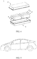
FIG. 4 is an exploded diagram ofFIG. 3 . -
FIG. 5 is a schematic diagram of an embodiment of an apparatus using a secondary battery as a power source. - Reference numerals in the accompanying drawings are described as follows:
- 1.
- battery pack;
- 2.
- upper cabinet body;
- 3.
- lower cabinet body;
- 4.
- battery module; and
- 5.
- secondary battery.
- The following describes in detail the negative electrode plate, the secondary battery, the battery module, the battery pack, and the apparatus in this application.
- First, the negative electrode plate provided in the first aspect of this application is described. The negative electrode plate comprises a negative current collector, a first active substance layer disposed on at least one surface of the negative current collector, and a second active substance layer disposed on the first active substance layer;
- wherein the first active substance layer comprises a first negative active substance, and the second active substance layer comprises a second negative active substance; and
- in the negative electrode plate, the following relationships are satisfied: 3.5 ≤ A/B ≤ 10.0, and 6.5 ≤ C/D ≤ 23.0, where
- A is gram capacity of the first negative active substance;
- B is thickness of the first active substance layer;
- C is gram capacity of the second negative active substance; and
- D is thickness of the second active substance layer.
- Preferably, in the negative electrode plate of this application, 6.5 ≤ A/B ≤ 8.5.
- Preferably, in the negative electrode plate of this application, 8.0 ≤ C/D ≤ 11.0.
- The inventors of this application have found that, under same raw materials and same processing technique, a negative active substance with larger gram capacity means a negative active substance with a crystal structure that is closer to the complete layered structure of ideal graphite, and that has a higher degree of ordering, fewer defects, thereby resulting in fewer side reactions and fewer negative active substances needed for a battery having an expected capacity. Therefore, larger gram capacity of the negative active substance better helps improve energy density of the battery. However, when the gram capacity of the negative active substance is excessively large, a spacing between graphite material layers is excessively small, solid-phase diffusion resistance of active ions inside a material is relatively large, and it is difficult for the active ions to migrate into and out the negative active substance, thereby degrading high-rate charging capability of the battery.
- The inventors of this application have further found that smaller thickness of an active substance layer of the negative electrode plate allows better infiltration of electrolyte into the negative electrode plate and faster liquid-phase conduction of active ions in the electrode plate. As a result, during long-term cycling of the battery, polarization of the battery is not significantly increased, and less side reactions occur, thereby reducing safety issues caused by formation of lithium dendrites on a surface of a negative electrode. However, excessively small thickness of the layer imposes a high requirement on a battery cell manufacturing process, and causes that the electrode plate is prone to exhibit "scratches", resulting in poor appearance. In addition, if thickness of a battery cell is excessively small, capacity per unit area of the electrode plate is undesirably small, greatly affecting energy density of the battery.
- If an optimization is independently made from the perspective of either gram capacity or thickness of an active substance layer of the electrode plate, great limitations are present to achieve a secondary battery with high energy density, long cycle life, and fast charging performance at the same time.
- Through extensive research, the inventors of this application have found that by designing a negative electrode plate with a two-layer structure, and adjusting a ratio of thickness of an active substance layer to gram capacity of a negative active substance so that the negative electrode plate satisfies the following relationships: 3.5 ≤ A/B ≤ 10.0, and 6.5 ≤ C/D ≤ 23.0, the battery can have high energy density, long cycle life, and fast charging at the same time.
- In the negative electrode plate designed in this application, the first negative active substance in the first active substance layer has high gram capacity. As a result, on the one hand, with the same thickness, higher capacity can be provided, so that capacity per unit area is increased. On another hand, higher gram capacity of the negative active substance means smaller mass of an active substance required to achieve same capacity per unit area, and higher energy density of a battery cell. If A/B is less than 3.5, it indicates that the gram capacity of the first active substance is undesirably low or the thickness of the first active substance layer is excessively large. In case of A/B less than 3.5, with the same capacity per unit area, the quantity of active sites on a material surface increases. In addition, the increased thickness of the active substance layer also causes an extended liquid transmission path of active ions, and increased resistance, thereby resulting in an increase in polarization and side reactions, and further affecting cycle life of battery cell. If A/B is greater than 10.0, it indicates that the gram capacity of the first active substance is undesirably large or the thickness of the active substance layer is excessively small. Higher gram capacity indicates a smaller spacing between negative active substance layers, hindering solid-phase diffusion of active ions and affecting fast charging capability of the battery. In addition, significantly small thickness of the electrode plate imposes a high requirement on a battery cell manufacturing process, and causes that the electrode plate is prone to exhibit "scratches", resulting in poor appearance and affecting performance of battery cells. In the negative electrode plate designed in this application, the second negative active substance in the second active substance layer has relatively small gram capacity. Correspondingly, a spacing between negative active substance layers is larger, solid-phase conduction of active ions is easier, and the active ions are more easily reduced in high-rate charging, thereby reducing formation of dendrites on a surface of a negative electrode. If C/D is less than 6.5, it indicates that the thickness of the second active substance layer is excessively large or the gram capacity of the active substance is excessively small. In the case of C/D less than 6.5, the active substance has excessively low degree of ordering, an increased quantity of defects in active substance crystals, and enhanced surface activity. As a result, during cycling, an SEI film is repeatedly broken and repaired. In this process, more active lithium is consumed, causing a decline in a battery capacity. In addition, the thickness of the electrode plate is excessively large, so that a transmission path of active ions is excessively long, affecting fast charging capability of the battery. If C/D is greater than 23.0, it indicates that the gram capacity of the second active substance is excessively large or the thickness of the second active substance layer is excessively small. Excessively larger gram capacity indicates a smaller spacing between crystal faces of the material, so that resistance of active ions to migrating into and out the active substance increases, and it is also likely to increase a volume expansion ratio of the material. This affects fast charging capability of the battery and structural stability of the material.
- In some embodiments of this application, a lower limit of A/B may be 5.5, 6.0, 6.5, or 7.0, and an upper limit of A/B may be 7.5, 8.0, 8.5, 9.0, 9.5, or 10.0.
- In some embodiments of this application, a lower limit of C/D may be 6.5, 7.0, 7.5, 8.0, 8.5, 9.0, or 10.0, and an upper limit of C/D may be 11.0, 12.0, 13.0, 14.0, 15.0, 18.0, 20.0, or 23.0. Preferably, in the negative electrode plate of this application, the gram capacity A of the first negative active substance is greater than the gram capacity C of the second negative active substance. More preferably, in the negative electrode plate, 0.70 ≤ C/A ≤ 0.98. When the second negative active substance has smaller gram capacity than the first negative active substance, a spacing between active substance layers is larger, thereby facilitating fast intercalation and deintercalation of active ions, and improving fast charging performance of the battery. In addition, the gram capacity of the first active substance is larger, so that the battery can have smaller thickness of the active substance layer while achieving same energy density. This better facilitates diffusion of active ions, thereby further improving cycle life of the battery.
- Preferably, in the negative electrode plate of this application, the thickness B of the first active substance layer is greater than or equal to the thickness D of the second active substance layer. Preferably, in the negative electrode plate, 0.2 ≤ D/B ≤ 1.0. During cycling of the battery, if the thickness of the second active substance layer is smaller, active ions can be intercalated into the first active substance layer through the second active substance layer in a shorter time, thereby reducing lithium precipitation caused by accumulation of active ions on a surface of the electrode plate. This can further improve the fast charging performance of the battery. Preferably, in the negative electrode plate of this application, C/D ≥ A/B. The gram capacity of the second active substance is larger, or the thickness of the second active substance layer is smaller, so that active ions released from positive electrode can quickly pass through the second active substance layer to reach the first active substance layer, thereby reducing safety issues resulting from dendrites formed due to accumulation of active ions on the surface of the electrode plate.
- Preferably, in the negative electrode plate of this application, the gram capacity A of the first negative active substance satisfies the following relationship: 355 mAh/g ≤ A ≤ 380 mAh/g, preferably, 360 mAh/g ≤ A ≤ 375 mAh/g.
- Preferably, in the negative electrode plate of this application, the thickness B of the first active substance layer satisfies the following relationship: 35 µm ≤ B ≤ 105 µm, preferably, 40 µm ≤ B ≤ 60 µm.
- Preferably, in the negative electrode plate of this application, the gram capacity C of the second negative active substance satisfies the following relationship: 250 mAh/g ≤ A ≤ 350 mAh/g, preferably, 300 mAh/g ≤ A ≤ 345 mAh/g.
- Preferably, in the negative electrode plate of this application, the thickness D of the second active substance layer satisfies the following relationship: 15 µm ≤ D ≤ 55 µm, preferably, 20 µm ≤ D ≤ 40 µm.
- Preferably, in the negative electrode plate of this application, the first negative active substance and the second negative active substance are independently selected from one or more of artificial graphite, natural graphite, carbonaceous mesophase spherules, soft carbon, and hard carbon.
- Preferably, in the negative electrode plate of this application, a degree of graphitization of the first negative active substance is greater than a degree of graphitization of the second negative active substance.
- A higher degree of graphitization of the first active substance means a higher degree of ordering of the active substance, fewer defects such as stacking faults and dislocations in crystals, and lower surface activity, so that it is easy to form a stable and dense SEI film during cycling, helping improve cycle performance. A lower degree of graphitization of the second active substance means a larger spacing between crystal faces of the material, facilitating migration into and out of active ions in the active substance, reducing the resistance to migrate, and reducing accumulation of active ions on the surface of the electrode plate that affects the fast charging capability of the battery. Therefore, it is ensured that the degree of graphitization of the first negative active substance is greater than that of the second negative active substance. This can ensure not only required energy density of battery cells, but also fast charging capability of the battery cells.
- A second aspect of this application provides a secondary battery, comprising a positive electrode plate, a negative electrode plate, a separator, and an electrolyte, wherein the negative electrode plate is the negative electrode plate provided in the first aspect of this application.
- In the secondary battery in the second aspect of this application, the positive electrode plate comprises a positive current collector, and a positive membrane that is provided on at least one surface of the positive current collector and that comprises a positive active substance.
- In the secondary battery in the second aspect of this application, the type of the positive active substance is not specifically limited, and the positive active substance may be a well-known conventional material that can be used as a positive active substance for a secondary battery in existing batteries. For example, the positive active substance may be selected from lithium cobalt oxide, lithium nickel oxide, lithium manganese oxide, lithium nickel manganese oxide, lithium nickel cobalt manganese oxide, lithium nickel cobalt aluminum oxide, olivine-type li-contained phosphate. One type of these positive active substances may be used alone, or two or more types may be used in combination. Preferably, the positive active substance is selected from one or more of LiCoO2, LiNiO2, LiMnO2, LiMn2O4, LiNi1/3Co1/3Mn1/3O2 (NCM333), LiNi0.5Co0.2Mn0.3O2(NCM523), LiNi0.6Co0.2Mn0.2O2(NCM622), LiNi0.8Co0.1Mn0.1O2(NCM811), LiNi0.85Co0.15Al0.05O2, LiFePO4 (LFP), and LiMnPO4.
- In the secondary battery in the second aspect of this application, the type of the separator is not specifically limited, and the separator may be, but not limited to, any separator materials used in existing batteries, for example, polyethylene, polypropylene, polyvinylidene fluoride, and a multilayer composite film thereof.
- In the secondary battery in the second aspect of this application, the electrolyte comprises an electrolyte salt and an organic solvent. Specific types and compositions of the electrolyte salt and the organic solvent are not specifically limited, and may be selected according to actual needs. The electrolyte may further comprise an additive. The type of the additive is not particularly limited, and the additive may be a negative film-forming additive, a positive film-forming additive, or an additive that can improve specific performance of the battery, for example, an additive for improving overcharge performance of the battery, an additive for improving high-temperature performance of the battery, or an additive for improving low-temperature performance of the battery.
- A third aspect of this application provides a battery module, comprising any one or more of the secondary batteries in the second aspect of this application.
- Further, the quantity of secondary batteries included in the battery module may be adjusted based on application and capacity of the battery module.
- In some embodiments, referring to
FIG. 1 and FIG. 2 , in thebattery module 4, a plurality ofsecondary batteries 5 may be sequentially arranged along a length direction of thebattery module 4; or certainly, may be arranged in any other manner. Further, the plurality ofsecondary batteries 5 may be fixed by using fasteners. - Optionally, the
battery module 4 may further comprise a housing with an accommodating space, and the plurality ofsecondary batteries 5 are accommodated in the accommodating space. - A fourth aspect of this application provides a battery pack, comprising any one or more of the battery modules in the third aspect of this application. In other words, the battery pack comprises any one or more of the secondary batteries in the first aspect of this application. The quantity of battery modules in the battery pack may be adjusted based on application and capacity of the battery pack.
- In some embodiments, referring to
FIG. 3 andFIG. 4 , thebattery pack 1 may comprise a battery cabinet and a plurality ofbattery modules 4 disposed in the battery cabinet. The battery cabinet comprises anupper cabinet body 2 and a lower cabinet body 3. Theupper cabinet body 2 can cover the lower cabinet body 3 to form an enclosed space for accommodating thebattery modules 4. The plurality ofbattery modules 4 may be arranged in the battery cabinet in any manner. - A fifth aspect of this application provides an apparatus, comprising any one or more of the secondary batteries in the first aspect of this application. The secondary battery may be used as a power source of the apparatus.
- Preferably, the apparatus may be, but not limited to, a mobile device (for example, a mobile phone or a notebook computer), an electric vehicle (for example, a full electric vehicle, a hybrid electric vehicle, a plug-in hybrid electric vehicle, an electric bicycle, an electric scooter, an electric golf vehicle, or an electric truck), an electric train, a ship, a satellite, an energy storage system, and the like.
- For example,
FIG. 5 shows an apparatus comprising the secondary battery in this application. The apparatus is a full electric vehicle, a hybrid electric vehicle, a plug-in hybrid electric vehicle, or the like. The secondary battery in this application supplies power to the apparatus. - The battery module, the battery pack, and the apparatus as described above comprise the secondary battery provided in this application, and therefore have at least the same advantages as the secondary battery. Details are not described herein again.
- The following uses a lithium-ion battery as an example to further describe this application with specific embodiments and reference embodiments. These embodiments are merely intended to describe this application, and this application is not limited to the following embodiments. Any modification or equivalent replacement of the technical solutions of this application without departing from the scope of the technical solutions of this application shall fall within the protection scope of this application.
- Batteries in Examples and Comparative Examples were all prepared according to the following method.
- Positive electrode plate: An active substance LiNi0.8Mn0.1Co0.1O2 (NCM811), a conductive agent acetylene black, and a binder polyvinylidene fluoride (PVDF) in an N-methylpyrrolidone solvent system based on a weight ratio of 96.8:2.2:1 were fully stirred and evenly mixed. The resulting mixture was applied onto an aluminum foil, followed by drying and cold pressing, to obtain a positive electrode plate.
- Negative electrode plate: First negative active substance (see Table 1 for details), Super P, sodium carboxymethyl cellulose, and a styrene-butadiene rubber (SBR) latex based on a weight ratio of 96.2:0.8:1.2:1.8 were mixed to obtain a first negative active substance slurry. The slurry was applied onto both surfaces of a current collector (a copper foil) to obtain first active substance layers. Second negative active substance (see Table 1 for details), Super P, sodium carboxymethyl cellulose, and a styrene-butadiene rubber (SBR) latex based on a weight ratio of 96.2: 0.8: 1.2: 1.8 were mixed to obtain a second negative active substance slurry. The slurry was applied onto the first active substance layers to obtain second active substance layers. After cold pressing and cutting, a negative electrode plate was obtained.
- Separator: A PE porous polymer film was used as a separator.
- Electrolyte: Ethylene carbonate (EC), ethyl methyl carbonate (EMC), and diethyl carbonate (DEC) based on a volume ratio of 3:6:1 were mixed. Dried lithium salt LiPF6 was then fully dissolved in the mixed organic solvent, to obtain an electrolyte in a concentration of 1 mol/L. Full battery preparation: The positive electrode plate, the separator, and the negative electrode plate were stacked in order, so that the separator was placed between the positive and negative electrodes, and has an effect of separation. Then the stack was wound to obtain a bare battery. The bare battery was placed in an outer packaging case. Then the prepared electrolyte was injected into the dried bare battery. After steps including vacuum packaging, standing, forming, and shaping, a lithium-ion secondary battery was obtained.
- Batteries in Examples 2 to 13 and Comparative Examples 1 to 6 were all prepared according to a method similar to that in Example 1, with specific differences as shown in Table 1. Table 1 showed parameters in Examples 1 to 13 and Comparative Examples 1 to 6.
Table 1 No. Type of first active substance Degree of graphitization of first active substance, % A (mAh/g) B (µm) Type of second active substance Degree of graphitization of second active substance, % C (mAh/g) D (µm) Example 1 Artificial 96 365 40 Artificial 93 340 40 Example 2 Artificial 96 365 45 Artificial 93 340 35 Example 3 Artificial 96 365 50 Artificial 93 340 30 Example 4 Artificial 96 365 55 Artificial 93 340 25 Example 5 Artificial 96 365 60 Artificial 93 340 20 Example 6 Artificial 96 360 50 Artificial 94 345 35 Example 7 Artificial 96 365 50 Artificial 92 335 35 Example 8 Artificial 98 370 50 Artificial 90 325 35 Example 9 Artificial 98 375 50 Artificial 88 300 35 Example 10 Artificial 98 375 40 Artificial 93 340 20 Example 11 Artificial 98 375 100 Artificial 93 340 50 Example 12 Natural 98 370 50 Artificial 93 340 35 Example 13 Natural 98 375 50 Artificial 93 340 35 Comparative Example 1 Artificial 96 365 35 Artificial 95 340 40 Comparative Example 2 Artificial 96 365 110 Artificial 93 340 20 Comparative Example 3 Artificial 96 365 50 Artificial 80 200 30 Comparative Example 4 Artificial 96 365 50 Artificial 95 355 15 Comparative Example 5 Artificial 95 355 105 Artificial 85 250 50 Comparative Example 6 Artificial 98 380 35 Artificial 94 350 15 - In the table, A represents gram capacity of first negative active substance, B represents thickness of first active substance, C represents gram capacity of second negative active substance, and D represents thickness of second active substance layer.
- Full battery cycle performance tests in Examples and Comparative Examples were all performed according to the following method comprising the steps of:
Performing at the first time charging and discharging at 25°C, and performing constant-current and constant-voltage charging at a charge current of 1.0C (that is, a current value of a theoretical capacity is completely discharged within 1 hour) until an upper-limit voltage was 4.2 V; Then performing constant-current discharging at a discharge current of 1.0C until a final voltage was 2.8 V; and recording a discharge capacity at the first cycle; Then performing repeatedly charge and discharge cycling.
- Lithium precipitation rate was tested by the following steps of: Performing a charge and discharge test at 25°C, and performing constant-current discharging at a discharge current of 1.0C (that is, a current value of a theoretical capacity is completely discharged within 1 hour) until a voltage was 2.8 V; Then performing constant-current charging at a charge current of 1.0C until a voltage was 4.2 V, and then performing constant-voltage charging until a current was 0.05C. At this point, the battery was in a fully charged state. Placing the fully charged battery still for 5 min, and performing constant-current discharging to 2.8 V at a discharge current of 1.0C. At this point, discharge capacity was an actual capacity of the battery at 1.0C, and denoted as C0. Then charging the battery to 4.2 V at a constant current of xC0, then performing constant-voltage charging until a current was 0.05C0, placing the battery still for 5 min, disassembling the battery, observing lithium precipitation status on an interface, adjusting a charging rate until lithium precipitation occured, and reporting the adjusted charging rate as lithium precipitation rate.
- Cyclic expansion rate was tested by the following steps of: Performing at the first time charging and discharging at 45°C, and performing constant-current and constant-voltage charging at a charge current of 1.0C (that is, a current value of a theoretical capacity is completely discharged within 1 hour) until an upper-limit voltage was 4.2 V. Then performing constant-current discharging at a discharge current of 1.0C until a final voltage was 2.8 V, and recording the discharge capacity at the first cycle. Then performing repeatedly charge and discharge cycling for 600 times, followed by removing the battery, and stopping the test.
- Performing a charge test at 25°C; Performing constant-current charging at a charge current of 1.0C (that is, a current value of a theoretical capacity is completely discharged within 1 h) until a voltage was 4.2 V, and then performing constant-voltage charging until a current was 0.05C. At this point, the battery was in a fully charged state. Disassembling a battery cell, taking out a negative electrode plate, and recording thickness H600 of the negative electrode plate.

- H0 is thickness of a copper foil, and H1 is thickness of the electrode plate after 1 cycle of test. According to the foregoing methods, cycle performance, a lithium precipitation rate, and an expansion rate after 600 cycles of the batteries in the embodiments and the reference embodiments were measured.
- For details about test results of Examples and Comparative Examples, see Table 2. Table 2 showed performance test results of Examples 1 to 13 and Comparative Examples 1 to 6.
Table 2 No. A/B C/D Capacity retention rate after 1000 cycles, % Lithium precipitation rate Expansion rate after 600 cycles Example 1 9.1 8.5 90 1.4C 29% Example 2 8.1 9.7 92 1.6C 30% Example 3 7.3 11.3 91 1.5C 28% Example 4 6.6 13.6 90 1.4C 32% Example 5 6.1 17.0 89 1.3C 34% Example 6 7.2 9.9 94 2.0C 28% Example 7 7.3 9.6 95 2.1C 26% Example 8 7.4 9.3 93 1.8C 24% Example 9 7.5 8.6 89 1.5C 30% Example 10 9.4 17.0 86 1.3C 34% Example 11 3.8 6.8 85 1.4C 33% Example 12 7.4 9.7 88 1.5C 36% Example 13 7.5 9.7 87 1.5C 38% Comparative Example 1 10.4 8.5 82 0.7C 44% Comparative Example 2 3.3 17.0 84 0.5C 45% Comparative Example 3 7.3 6.7 80 1.0C 40% Comparative Example 4 7.3 23.7 83 0.5C 46% Comparative Example 5 3.4 5.0 70 0.6C 43% Comparative Example 6 10.9 23.3 75 0.4C 47% - In the table, A represents gram capacity of the first negative active substance, B represents thickness of the first active substance layer, C represents gram capacity of the second negative active substance, and D represents thickness of the second active substance layer.
- In Examples 1 to 13, ratios of thickness of each active substance layer to gram capacity of the active substance layer were properly adjusted, so that when 3.5 ≤ A/B ≤ 10.0 and 8.0 ≤ C/D ≤ 23.0, the batteries were characterized by all of long cycle life, high-rate charging, and low expansion rate.
- Compared with Examples 1 to 13, in Comparative Examples 1 to 6, the batteries were not in the given ranges of A/B and C/D at the same time, and therefore the batteries were not characterized by all of a long cycle life, a high energy density, and high-rate charging.
- In Comparative Examples 1 and 2, where A/B was within the given range but C/D was not within the given range, the batteries exhibited deteriorated cycle, lithium precipitation, and expansion performance. In Comparative Example 1, the thickness of the first negative active substance layer was not within the given range of 35 µm-105 µm, and the thickness of the electrode plate was excessively small. This was likely to cause "scratches", thereby greatly affecting appearance of the electrode plate when the gram capacity of the active substance was within the given specification range, and further affecting cycle performance of the battery. In addition, if the thickness of the first active substance layer was excessively small, energy density of the battery was affected. In Comparative Example 2, the thickness of the first negative active substance layer was not within the given range of 35-105 µm. If the thickness of the electrode plate was excessively large, infiltration of an electrolyte into the electrode plate was difficult, resulting in an increase in a transmission resistance of active ions and an increase in polarization of the battery. This leaded to uneven local current distribution in the battery and caused lithium precipitation, thereby affecting cycle life and lithium precipitation performance of the battery.
- In Comparative Example 3 and 4, where A/B was not within the given range and C/D was within the given range, cycle, lithium precipitation, and expansion performance of the battery were significantly affected. In Comparative Example 3, the gram capacity of the second negative active substance was not within the selected range of 250 mAh/g-350 mAh/g, and the gram capacity of the active substance was relatively small, resulting in a quite low energy density of the battery cell when the thickness of the electrode plate was within the given specification range. In addition, the active substance has excessively low degree of ordering, an increased quantity of defects in active substance crystals, and enhanced surface activity. As a result, during cycling, an SEI film was repeatedly broken and repaired, causing a decline in a battery capacity, and affecting cycle life of the battery when the thickness of the electrode plate was within the given specification range. In Comparative Example 4, the gram capacity of the second negative active substance was not within the selected range of 250 mAh/g-350 mAh/g, the gram capacity of the active substance was excessively large, and a spacing between active substance layers was relatively small, thereby affecting solid transmission of active ions, and affecting lithium precipitation and expansion performance of the battery when the thickness of the electrode plate was within the given specification range.
- In Comparative Example 5 and 6, although the gram capacity of the active substance and the thickness of the active substance layer were within the given ranges, neither A/B nor C/D was within the given range, so cycle, lithium precipitation, and expansion performance of the battery were affected.
- Although this application is disclosed above with preferred embodiments, these embodiments are not intended to limit the claims. Any person skilled in the art can make several possible changes and modifications without departing from the concept of this application. Therefore, the protection scope of this application shall be subject to the scope demarcated by the claims of this application.
Claims (15)
- A negative electrode plate, wherein the negative electrode plate comprises:a negative current collector, a first active substance layer disposed on at least one surface of the negative current collector, and a second active substance layer disposed on the first active substance layer,wherein the first active substance layer comprises a first negative active substance, and the second active substance layer comprises a second negative active substance; andin the negative electrode plate, the following relationships are satisfied: 3.5 ≤ A/B ≤ 10.0, and 6.5 ≤ C/D ≤ 23.0, whereinA is gram capacity of the first negative active substance;B is thickness of the first active substance layer;C is gram capacity of the second negative active substance; andD is thickness of the second active substance layer.
- The negative electrode plate according to claim 1, wherein in the negative electrode plate, 6.5 ≤ A/B ≤ 8.5.
- The negative electrode plate according to claim 1 or 2, wherein in the negative electrode plate, 8.0 ≤ C/D ≤ 11.0.
- The negative electrode plate according to any one of claims 1 to 3, wherein in the negative electrode plate, A > C.
- The negative electrode plate according to any one of claims 1 to 4, wherein in the negative electrode plate, 0.70 ≤ C/A ≤ 0.98.
- The negative electrode plate according to any one of claims 1 to 5, wherein in the negative electrode plate, B ≥ D.
- The negative electrode plate according to any one of claims 1 to 6, wherein in the negative electrode plate, 0.2 ≤ D/B ≤ 1.0.
- The negative electrode plate according to any one of claims 1 to 7, wherein in the negative electrode plate, C/D ≥ A/B
- The negative electrode plate according to any one of claims 1 to 8, wherein in the negative electrode plate, 355 mAh/g ≤ A ≤ 380 mAh/g, preferably, 360 mAh/g ≤ A ≤ 375 mAh/g; and/or35 µm ≤ B ≤ 105 µm, preferably, 40 µm ≤ B ≤ 60 µm; and/or250 mAh/g ≤ C ≤ 350 mAh/g, preferably, 300 mAh/g ≤ C ≤ 345 mAh/g; and/or15 µm ≤ D ≤ 55 µm, preferably, 20 µm ≤ D ≤ 40 µm.
- The negative electrode plate according to any one of claims 1 to 9, wherein the first negative active substance and the second negative active substance are independently selected from one or more of artificial graphite, natural graphite, carbonaceous mesophase spherules, soft carbon, and hard carbon.
- The negative electrode plate according to any one of claims 1 to 10, wherein a degree of graphitization of the first negative active substance is greater than a degree of graphitization of the second negative active substance.
- A secondary battery (5), comprising a positive electrode plate, a negative electrode plate, a separator, and an electrolyte, wherein the negative electrode plate is the negative electrode plate according to any one of claims 1 to 11.
- A battery module (4), comprising the secondary battery (5) according to claim 12.
- A battery pack (1), comprising the battery module (4) according to claim 13.
- An apparatus, comprising the secondary battery (5) according to claim 12, wherein the secondary battery (5) is used as a power source of the apparatus; and
preferably, the apparatus comprises a mobile device, an electric vehicle, an electric train, a satellite, a ship, and an energy storage system.
Applications Claiming Priority (2)
| Application Number | Priority Date | Filing Date | Title |
|---|---|---|---|
| CN201811284003.7A CN111129503B (en) | 2018-10-31 | 2018-10-31 | Negative pole piece and secondary battery |
| PCT/CN2019/111049 WO2020088231A1 (en) | 2018-10-31 | 2019-10-14 | Negative electrode piece, secondary battery, battery module, battery pack and device |
Publications (2)
| Publication Number | Publication Date |
|---|---|
| EP3783709A1 true EP3783709A1 (en) | 2021-02-24 |
| EP3783709A4 EP3783709A4 (en) | 2021-10-13 |
Family
ID=70462934
Family Applications (1)
| Application Number | Title | Priority Date | Filing Date |
|---|---|---|---|
| EP19880120.1A Pending EP3783709A4 (en) | 2018-10-31 | 2019-10-14 | Negative electrode piece, secondary battery, battery module, battery pack and device |
Country Status (4)
| Country | Link |
|---|---|
| US (1) | US11664495B2 (en) |
| EP (1) | EP3783709A4 (en) |
| CN (2) | CN111129503B (en) |
| WO (1) | WO2020088231A1 (en) |
Families Citing this family (6)
| Publication number | Priority date | Publication date | Assignee | Title |
|---|---|---|---|---|
| CN111490253B (en) * | 2019-01-29 | 2021-12-10 | 宁德时代新能源科技股份有限公司 | Negative pole piece and lithium ion secondary battery thereof |
| CN111987286B (en) * | 2020-09-14 | 2021-10-26 | 珠海冠宇电池股份有限公司 | Negative plate and lithium ion battery comprising same |
| CN112018327B (en) * | 2020-09-21 | 2021-10-15 | 珠海冠宇电池股份有限公司 | Negative plate, preparation method and battery |
| CN113871616A (en) * | 2021-09-28 | 2021-12-31 | 东莞维科电池有限公司 | Negative pole piece, preparation method thereof and lithium ion battery |
| CN117015870A (en) * | 2021-11-11 | 2023-11-07 | 宁德时代新能源科技股份有限公司 | Secondary battery and electricity utilization device |
| CN117558918A (en) * | 2024-01-12 | 2024-02-13 | 宁德时代新能源科技股份有限公司 | Secondary battery and electricity utilization device |
Family Cites Families (11)
| Publication number | Priority date | Publication date | Assignee | Title |
|---|---|---|---|---|
| JP4622803B2 (en) * | 2005-10-25 | 2011-02-02 | ソニー株式会社 | Negative electrode for lithium ion secondary battery, lithium ion secondary battery, and production method thereof |
| JP2008059999A (en) * | 2006-09-01 | 2008-03-13 | Sony Corp | Negative electrode and nonaqueous electrolyte secondary battery using it |
| KR101300107B1 (en) * | 2010-10-19 | 2013-08-30 | 주식회사 엘지화학 | Negative electrode for secondary battery, method for preparing thereof and secondary battery comprising the same |
| JP5673690B2 (en) * | 2010-12-06 | 2015-02-18 | トヨタ自動車株式会社 | Lithium ion secondary battery and method for producing lithium ion secondary battery |
| JP2014120404A (en) * | 2012-12-18 | 2014-06-30 | Mitsubishi Motors Corp | Secondary battery |
| KR101558774B1 (en) * | 2013-05-23 | 2015-10-08 | 주식회사 엘지화학 | Lithium secondary battery comprising multilayered active materials |
| CN103633293B (en) * | 2013-11-08 | 2017-02-15 | 鲍添增 | Lithium ion battery negative electrode piece using hard carbon and soft carbon as active materials and lithium ion battery |
| CN105470460B (en) * | 2015-03-12 | 2019-02-01 | 万向一二三股份公司 | A kind of anode plate for lithium ionic cell and preparation method thereof |
| CN108666525A (en) * | 2017-04-01 | 2018-10-16 | 宁德时代新能源科技股份有限公司 | Negative pole piece, preparation method thereof and secondary battery |
| TWI663128B (en) * | 2018-03-27 | 2019-06-21 | 國立清華大學 | Electrode material for secondary battery and secondary battery |
| US20220293924A1 (en) * | 2021-03-15 | 2022-09-15 | Nanode Battery Technologies Ltd. | Tin Alloy Sheets as Negative Electrodes for Non-Aqueous Li and Na-ion Batteries |
-
2018
- 2018-10-31 CN CN201811284003.7A patent/CN111129503B/en active Active
- 2018-10-31 CN CN202110585547.2A patent/CN113328099B/en active Active
-
2019
- 2019-10-14 WO PCT/CN2019/111049 patent/WO2020088231A1/en unknown
- 2019-10-14 EP EP19880120.1A patent/EP3783709A4/en active Pending
- 2019-10-14 US US17/051,187 patent/US11664495B2/en active Active
Also Published As
| Publication number | Publication date |
|---|---|
| CN111129503A (en) | 2020-05-08 |
| CN111129503B (en) | 2021-06-15 |
| CN113328099A (en) | 2021-08-31 |
| WO2020088231A1 (en) | 2020-05-07 |
| CN113328099B (en) | 2022-07-19 |
| EP3783709A4 (en) | 2021-10-13 |
| US11664495B2 (en) | 2023-05-30 |
| US20210135200A1 (en) | 2021-05-06 |
Similar Documents
| Publication | Publication Date | Title |
|---|---|---|
| US11258060B2 (en) | Negative electrode plate, secondary battery, battery module, battery pack, and apparatus | |
| US11664495B2 (en) | Negative electrode plate, secondary battery, battery module, battery pack, and apparatus | |
| WO2022206877A1 (en) | Electrochemical device and electronic device | |
| KR102227302B1 (en) | Positive electrode active material compositiom for secondary battery and secondary battery comprising the same | |
| EP3955349A1 (en) | Negative electrode active material, manufacturing method therefor, secondary battery, and device comprising secondary battery | |
| KR20180129184A (en) | Method for preparing positive electrode, positive electrode for secondary battery prepared by the same and lithium secondary battery comprising the same | |
| US20200212439A1 (en) | Negative electrode active material, negative electrode plate and battery | |
| US11631852B2 (en) | Secondary battery, preparation method thereof, and battery module, battery pack, and apparatus associated therewith | |
| EP4228053A1 (en) | Battery pack and electric apparatus using same | |
| EP4170755A1 (en) | Positive electrode material, positive electrode pole piece, lithium secondary battery, battery module, battery pack, and apparatus | |
| EP4167324A1 (en) | Secondary battery, preparation method therefor, and battery module, battery package and device containing same | |
| US20220069355A1 (en) | Lithium metal battery | |
| EP3965201A1 (en) | Secondary battery and device containing same | |
| US11962007B2 (en) | Lithium-ion secondary battery, battery module, battery pack, and powered device | |
| KR20190057950A (en) | Electrode assembly and lithium secondary battery comprising the same | |
| KR20210071612A (en) | Positive electrode material for lithium secondary battery and preparing method of the same | |
| US20220102724A1 (en) | Secondary battery and apparatus containing the secondary battery | |
| CN115986053A (en) | Negative electrode sheet, secondary battery, and power consumption device | |
| KR102459882B1 (en) | Positive electrode for lithium secondary battery and lithium secondary battery including the same | |
| KR20220110122A (en) | Positive electrode and lithium secondary batter including the same | |
| KR20210080249A (en) | Positive electrode for lithium secondary battery, lithium secondary battery including the same | |
| EP4322244A1 (en) | Negative electrode sheet, secondary battery, battery module, battery pack, and electric apparatus | |
| EP4354527A1 (en) | Electrode plate and preparation method therefor | |
| US20240128447A1 (en) | Positive Electrode Active Material, Manufacturing Method Thereof, and Positive Electrode for Lithium Secondary Battery Comprising the Same | |
| WO2023044625A1 (en) | Composite artificial graphite and preparation method therefor, secondary battery containing composite artificial graphite, and power-consuming apparatus |
Legal Events
| Date | Code | Title | Description |
|---|---|---|---|
| STAA | Information on the status of an ep patent application or granted ep patent |
Free format text: STATUS: THE INTERNATIONAL PUBLICATION HAS BEEN MADE |
|
| PUAI | Public reference made under article 153(3) epc to a published international application that has entered the european phase |
Free format text: ORIGINAL CODE: 0009012 |
|
| STAA | Information on the status of an ep patent application or granted ep patent |
Free format text: STATUS: REQUEST FOR EXAMINATION WAS MADE |
|
| 17P | Request for examination filed |
Effective date: 20201116 |
|
| AK | Designated contracting states |
Kind code of ref document: A1 Designated state(s): AL AT BE BG CH CY CZ DE DK EE ES FI FR GB GR HR HU IE IS IT LI LT LU LV MC MK MT NL NO PL PT RO RS SE SI SK SM TR |
|
| AX | Request for extension of the european patent |
Extension state: BA ME |
|
| A4 | Supplementary search report drawn up and despatched |
Effective date: 20210908 |
|
| RIC1 | Information provided on ipc code assigned before grant |
Ipc: H01M 4/525 20100101ALN20210903BHEP Ipc: H01M 4/505 20100101ALN20210903BHEP Ipc: H01M 4/36 20060101ALI20210903BHEP Ipc: H01M 4/04 20060101ALI20210903BHEP Ipc: H01M 4/133 20100101ALI20210903BHEP Ipc: H01M 4/66 20060101AFI20210903BHEP |
|
| DAV | Request for validation of the european patent (deleted) | ||
| DAX | Request for extension of the european patent (deleted) | ||
| STAA | Information on the status of an ep patent application or granted ep patent |
Free format text: STATUS: EXAMINATION IS IN PROGRESS |
|
| 17Q | First examination report despatched |
Effective date: 20220309 |
|
| GRAP | Despatch of communication of intention to grant a patent |
Free format text: ORIGINAL CODE: EPIDOSNIGR1 |
|
| STAA | Information on the status of an ep patent application or granted ep patent |
Free format text: STATUS: GRANT OF PATENT IS INTENDED |
|
| RIC1 | Information provided on ipc code assigned before grant |
Ipc: H01M 4/525 20100101ALN20240126BHEP Ipc: H01M 4/505 20100101ALN20240126BHEP Ipc: H01M 4/36 20060101ALI20240126BHEP Ipc: H01M 4/04 20060101ALI20240126BHEP Ipc: H01M 4/133 20100101ALI20240126BHEP Ipc: H01M 4/66 20060101AFI20240126BHEP |
|
| INTG | Intention to grant announced |
Effective date: 20240213 |
|
| GRAS | Grant fee paid |
Free format text: ORIGINAL CODE: EPIDOSNIGR3 |
|
| GRAA | (expected) grant |
Free format text: ORIGINAL CODE: 0009210 |
|
| STAA | Information on the status of an ep patent application or granted ep patent |
Free format text: STATUS: THE PATENT HAS BEEN GRANTED |