EP3783630A1 - Vorrichtung zum unterdrücken eines gleichstromanteils beim betrieb eines an ein hochspannungsnetz angeschlossenen elektrischen geräts - Google Patents
Vorrichtung zum unterdrücken eines gleichstromanteils beim betrieb eines an ein hochspannungsnetz angeschlossenen elektrischen geräts Download PDFInfo
- Publication number
- EP3783630A1 EP3783630A1 EP19193135.1A EP19193135A EP3783630A1 EP 3783630 A1 EP3783630 A1 EP 3783630A1 EP 19193135 A EP19193135 A EP 19193135A EP 3783630 A1 EP3783630 A1 EP 3783630A1
- Authority
- EP
- European Patent Office
- Prior art keywords
- switching
- circuit
- current
- unit
- core
- Prior art date
- Legal status (The legal status is an assumption and is not a legal conclusion. Google has not performed a legal analysis and makes no representation as to the accuracy of the status listed.)
- Granted
Links
Images

Classifications
-
- H—ELECTRICITY
- H01—ELECTRIC ELEMENTS
- H01F—MAGNETS; INDUCTANCES; TRANSFORMERS; SELECTION OF MATERIALS FOR THEIR MAGNETIC PROPERTIES
- H01F27/00—Details of transformers or inductances, in general
- H01F27/42—Circuits specially adapted for the purpose of modifying, or compensating for, electric characteristics of transformers, reactors, or choke coils
-
- H—ELECTRICITY
- H01—ELECTRIC ELEMENTS
- H01F—MAGNETS; INDUCTANCES; TRANSFORMERS; SELECTION OF MATERIALS FOR THEIR MAGNETIC PROPERTIES
- H01F27/00—Details of transformers or inductances, in general
- H01F27/34—Special means for preventing or reducing unwanted electric or magnetic effects, e.g. no-load losses, reactive currents, harmonics, oscillations, leakage fields
- H01F27/38—Auxiliary core members; Auxiliary coils or windings
-
- H—ELECTRICITY
- H01—ELECTRIC ELEMENTS
- H01F—MAGNETS; INDUCTANCES; TRANSFORMERS; SELECTION OF MATERIALS FOR THEIR MAGNETIC PROPERTIES
- H01F29/00—Variable transformers or inductances not covered by group H01F21/00
- H01F29/14—Variable transformers or inductances not covered by group H01F21/00 with variable magnetic bias
- H01F2029/143—Variable transformers or inductances not covered by group H01F21/00 with variable magnetic bias with control winding for generating magnetic bias
Definitions
- the invention relates to a device and a method for suppressing a direct current component when operating an electrical device connected to a high-voltage network.
- the invention also relates to an electrical device with such a device.
- GIC Garnier Induced Currents
- a direct current component results in a magnetic direct flux component in the core of the transformer, which is superimposed on the alternating flux.
- An asymmetrical modulation of the magnetic material in the core occurs, which has a number of disadvantages.
- a direct current of just a few amperes leads to saturation of the core with magnetic flux. This is associated with a significant increase in core losses (e.g. 20-30%). Heating problems can occur, especially with a large GIC.
- there is an increased noise emission during operation which is perceived as particularly annoying in particular when the transformer is operated in the vicinity of a living area.
- the device and the method mentioned in the introduction are thus in FIG EP 3 080 821 B1 described.
- the device disclosed there has a compensation winding which is part of a circuit.
- a switching branch is provided in series with the compensation winding, a choke and a thyristor being connected in series in the switching branch.
- Phase control is implemented with the aid of a control unit.
- the current flowing in the circuit via the switching branch is regulated by varying the phase shift between the ignition time of the thyristor and the voltage in the compensation circuit.
- the controllable current range can be increased by a second switching branch that is connected in parallel to the first switching branch.
- the achievable throughflow in the core can be increased by the second switching branch, so that larger direct current components can be compensated.
- the voltage-synchronous ignition of the thyristor or thyristors requires complex electronics, which are cost-intensive and require maintenance.
- the object of the invention is therefore to create a device, an electrical device and a method of the type mentioned at the beginning, which are inexpensive, reliable and low-maintenance.
- the invention solves this problem in that the device has a compensation winding for generating a magnetic flux in the core, the effect of which is opposite to the direct flux component, a circuit in which the compensation winding is arranged, at least one in the circuit and converter unit arranged in series with the compensation winding, which allows current to flow through it in only one Direction enables a number of switching branches which are arranged in the circuit parallel to one another and each in series with the compensation winding and with the converter unit, with a switching unit and a current limiting inductor being connected in series in each switching branch.
- the device according to the invention further comprises a control unit connected to each switching unit, which is set up to actuate each switching unit, so that a current flow is made possible over so many switching branches that an input signal of the control unit is minimized.
- the invention also achieves this object by means of an electrical device with a core and at least one winding which is set up to generate a magnetic flux in the core, the electrical device having an inventive device inductively coupled to the core.
- the invention achieves the object by a method in which an output signal of a sensor that detects the direct current component in one or the winding of an electrical device is fed to a control unit, the control unit actuates so many switching units that a current flow is established in a circuit , which has a compensation winding which is inductively coupled to a core of an electrical device, so that a direct flux component in the electrical device is minimized.
- a direct current flowing through a compensation winding is set by connecting and disconnecting current-limiting chokes arranged parallel to one another. All current limiting chokes are arranged in series with the compensation winding in a circuit in which a converter unit ensures the rectification of the current flowing in the circuit.
- the compensating direct current in the compensation throttle becomes greater the more switching branches are connected.
- a complex phase control has become superfluous within the scope of the invention.
- a simple digital control is sufficient.
- this switches on so many switching branches that the direct current component measured by a sensor in an electrical device is minimized.
- the circuit of the device according to the invention is expediently grounded at a potential point. This potential point is connected downstream of the switching branches in the direction of the current permitted by the converter unit in the circuit.
- the inductance acting in the circuit is changed in stages by switching the current limiting chokes on and off.
- the compensation winding in the circuit acts as an ideal voltage source.
- a voltage is induced in the compensation winding, which is inductively coupled to the winding or windings of the electrical device.
- This voltage drives a current rectified by the converter unit in the circuit, the size of which depends on the inductance set in the circuit.
- the circuit in which the compensation winding and the switching branches are arranged is a closed circuit that is earthed at one point.
- a direct current I DC thus flows on which an alternating current is superimposed, the amplitude of the alternating current approximately corresponding to the value of the direct current.
- ⁇ corresponds to the angular frequency of the alternating current.
- L stands for the inductance of the circuit.
- U eff is the rms value of the alternating voltage that is induced in the compensation winding.
- the electrical device When operating the electrical device, it is connected to a high-voltage network within the scope of the invention.
- the electrical device is therefore designed for high voltages and, for example, a transformer, in particular a power transformer or a choke.
- a transformer or such a choke preferably has a tank filled with an insulating fluid.
- An active part is arranged in the tank, which has a magnetizable core and at least one winding. At least one winding is connected to the high-voltage network during operation.
- An ester liquid or a mineral oil for example, can be used as the insulating fluid.
- it also serves to dissipate the heat generated in the components.
- any sensor can be considered as a sensor which detects direct currents and provides an electrical signal on the output side as a function of the magnitude of the direct current.
- the electrical signal can be an analog electrical signal, for example an electrical current or a voltage, the strength or intensity of which corresponds to the magnitude of the detected direct current.
- the output signal of the sensor can also be a digital signal, such as, for example, a sequence of digital values that have been generated, for example, by sampling an analog signal, obtaining sampling values and digitizing the sampling values.
- the electrical device is designed within the scope of the invention for operation in the voltage or high voltage network, ie for an operating voltage between 1 kV and 1200 kV, in particular 50 kV and 800 kV.
- the high voltage network is preferably an alternating voltage network.
- AC and DC voltage network is also possible within the scope of the invention.
- an electrical device for example a transformer, in particular a power transformer, a choke or the like.
- each switching unit is an electronic switching unit.
- An electronic switching unit or in other words an electronic switch, is, for example, a controllable power semiconductor that is transferred by a control or ignition signal from a blocking position, in which a current flow through the power semiconductor is interrupted, to a through position, in which a current flow through the power semiconductor switch is made possible.
- a controllable power semiconductor is, for example, a thyristor, GTO, IGBT, IGCT or the like.
- each electronic switching unit is a thyristor.
- Thyristors are particularly robust power semiconductors and are inexpensive on the market. Thyristors can only be actively transferred from a blocked position to the open position. In other words, they can only be switched on or on. In order to move from the pass-through position to the blocked position, the current flowing through the thyristor must fall below a holding current. However, this is guaranteed within the scope of the invention, since the compensation winding generates an alternating voltage in the circuit which, when the polarization changes, ensures a current in the circuit which falls below the holding current of the thyristor. If a circuit is to be switched on, the thyristor is continuously ignited.
- each switching unit has at least two thyristors connected in parallel in opposite directions.
- the thyristors serve not only as switches, but also as current limiting units or, in other words, as flow valves. If a thyristor is in its through position, the current can flow through it in only one direction. In other words, the thyristor directs the current at the same time.
- the current limiting chokes are expediently designed to be identical to or different from one another. If all current limiting reactors are identical, the current in the circuit can only be changed in uniform steps with the same interconnection of the current limiting reactors.
- each current limiting choke is composed of sub-coils, with two sub-coils being arranged next to one another between two metal plates to form a sub-coil pair, and each sub-coil being equipped with connection terminals.
- This construction of the current limiting chokes has proven to be particularly simple and robust.
- this design enables the introduction of an intermediate inductance, which will be discussed in more detail later.
- partial coil pairs are arranged one above the other, so that a coil stack is formed.
- the partial coil pairs share a metal plate.
- the thickness of the metal plate between two partial coil pairs, which are arranged one above the other is exactly as great as the thickness of the lower or upper metal plate of the stack. If two adjacent pairs of coil sections are active, almost no magnetic flux can be measured in this metal plate, so that the flux of the lower and upper pairs of coil sections cancel each other out.
- the metal plates with their constant thickness are necessary if an adjacent pair of sub-coils is not active, i.e. does not generate a magnetic field.
- Each metal plate advantageously consists of a ferromagnetic material. In this way the stray field losses are minimized.
- the partial coils of a partial coil pair are advantageously connected in series or in parallel with one another. This advantageous further development makes it possible to reduce the number of partial coil pairs required, so that material and structural volume can be saved. If the partial coils of a partial coil pair are not connected in series, but parallel to one another without otherwise changing the geometry, the inductance of the partial coil pair is quartered.
- the partial coils of a partial coil pair are of identical design.
- partial coils of different partial coil pairs have different numbers of turns and conductor cross-sections.
- the partial coils of a partial coil pair arranged further above or below in the stack can have a lower number of turns, but a larger conductor cross-section in order to be able to carry the higher currents which then occur without errors.
- Figure 1 shows an embodiment of the device 1 according to the invention, which shows a circuit 2 in which a compensation winding 3 is arranged.
- the compensation winding 3 is inductively coupled to a high-voltage winding of a power transformer, the power transformer being connected to a high-voltage network carrying AC voltage with a nominal voltage of 325 kV.
- a converter unit 4 can be seen in series with the compensation winding 3, which converter unit is designed, for example, as a diode.
- a diode can also be referred to as a non-controllable power semiconductor.
- the converter unit 4 enables current to flow through it in only one direction, which is defined by the tip of the triangle (i.e. in Figure 1 from left to right) is indicated.
- the grounded circuit 2 also has switching branches 5 1 , 5 2 , 5 3 ... 5 n-1 , 5 n connected in parallel.
- a switching unit 6 1 , 6 2 , 6 3 ... 6 n-1 , 6 n and a current limiting throttle 7 1 , 7 2 , 7 3 ... 7 n-1 , 7 n are connected in series.
- the switching units 6 1 , ... 6 n are in the in Figure 1 shown embodiment realized as thyristors, which take over the function of the figuratively shown diode 4.
- the diode 4 is therefore part of the switching unit and integrated into it. In other words, the rectifying effect of a converter unit is also taken over by the electronic switching unit. After ignition, a thyristor allows current to flow through it in only one direction.
- thyristor 6 1 ,... 6 n is connected via signal lines shown in dashed lines to a control unit 8 which is set up to ignite the respective thyristor.
- the control unit 8 is also connected to the output of a sensor 9, with the aid of which a direct current component is detected in one of the windings of the transformer, which is otherwise not shown.
- a signal is provided which corresponds to the direct flux component and which is transferred to the control unit 8.
- the compensation winding 3 inductively coupled to the high-voltage winding generates a voltage U in the circuit 2.
- the compensation winding 3 provides an ideal voltage source for the circuit 2.
- the induced voltage now drives a direct current with an alternating current component via the circuit 2.
- the size of this current flowing in the circuit is dependent on the number of active and parallel switching branches. The more switching branches are actively switched by igniting the thyristor assigned to it, the greater the current flowing in circuit 2, which is also established in compensation winding 3, so that due to the inductive coupling, a direct flux component in the core, which is caused by direct current flowing through the high voltage and / or low voltage winding is caused, is compensated.
- the control unit 8 is a particularly simple control unit, since it only connects switching branches in parallel by continuously igniting the thyristors or by omitting continuous ignition, so that the direct current component detected by the sensor 9 is minimized. A complex phase control is avoided within the scope of the invention. According to the invention, a simple, virtually error-free and robust device for direct current compensation is provided.
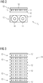
- Figure 2 illustrates the structure of an inductance 6 1 , ... 6 n as an example.
- the current limiting reactor 6 1 is composed of a pair of partial coils 10 and 11 which are arranged between two iron plates 12, the partial coils 10 and 11 being provided with taps or connection terminals, not shown in the figures.
- the two partial coils 10 and 11 form a partial coil pair 13.
- An inductance constructed in this way can be put together with other inductances in a particularly simple and compact manner to form a stack 14, with adjacent coil pairs 13 sharing a metal or iron plate 13 arranged between them.
- all of the metal plates 13 of the stack 14 have the same thickness. Only a metal plate is necessary between two pairs of coil sections 13 arranged one above the other.
- the metal plates are preferably designed to be identical to one another.
- the metal plates are preferably plates made of thin electrical steel sheets.
- the number of coil pairs required can be limited by means of an appropriate interconnection.
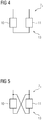
- two sub-coils 10 and 11 are connected in series as an example.
- Figure 5 shows the two partial coils 10 and 11 of a partial coil pair 13 connected in parallel. Since the partial coil pairs according to Figure 4 and Figure 5 otherwise not differentiate further, the partial coil pair 13 according to FIG Figure 5 only a quarter of the inductance of the partial coil pair according to Figure 4 on. If you designate partial coil pairs with full inductance with L1, see Figure 4 , and partial coil pairs according to Figure 5 that are connected in parallel with each other and thus have a quarter of the inductance of L1 with L2, 12 switching stages can be implemented with eight partial choke pairs, as can be seen from Table 1.
- n is the number of partial coil pairs with different inductances
- the number of possible switching stages results from 2 n -1.
- the partial coil pairs are graded in such a way that the following partial coil pair only has half the inductance. This means that with n partial coil pairs, 2 n -1 switching stages can be implemented with the same increments.
- the partial chokes 10 and 11 of a partial choke pair 13 are designed with only half the number of turns but with a doubling of the conductor cross-section compared to an adjacent partial choke pair, the size of the said partial choke pair remains approximately the same.
- the inductances of the partial choke pairs can now be quartered again, so that, according to this further development of the invention, four partial choke pairs with different inductances L1, L2, L4 and L8 result.
Landscapes
- Engineering & Computer Science (AREA)
- Power Engineering (AREA)
- Power Conversion In General (AREA)
Abstract
- einer Kompensationswicklung (3) zum Erzeugen eines magnetischen Flusses in dem Kern, dessen Wirkung dem Gleichflussanteil entgegengerichtet ist,
- einem Stromkreis (2), in dem die Kompensationswicklung (3) angeordnet ist,
- wenigstens einer in dem Stromkreis (2) und in Reihe zur Kompensationswicklung (3) angeordneten Stromrichtereinheit (4), die einen Stromfluss über diese in nur einer Richtung ermöglicht,
- einer Anzahl von Schaltzweigen (51, 52, ... 5n), die in dem Stromkreis parallel zueinander und jeweils in Reihe zur Kompensationswicklung (3) und zur Stromrichtereinheit (4) angeordnet sind, wobei in jedem Schaltzweig (51, 52, ... 5n) eine Schalteinheit (61, 62, ... 6n) und eine Strombegrenzungsdrossel (71, 72, ... 7n) in Reihe geschaltet sind, und
- einer mit jeder Schalteinheit (61, 62, ... 6n) verbundenen Steuerungseinheit (8), die zum Betätigen jeder Schalteinheit (61, 62, ... 6n) eingerichtet ist, so dass einen Stromfluss über so viele Schaltzweige (51, 52, ... 5n) ermöglicht ist, dass ein Eingangssignal der Steuerungseinheit (8) minimiert ist.
Description
- Die Erfindung betrifft eine Vorrichtung und ein Verfahren zum Unterdrücken einen Gleichstromanteils beim Betrieb eines an eine Hochspannungsnetz angeschlossenen elektrischen Geräts.
- Die Erfindung betrifft ferner ein elektrisches Gerät mit einer solchen Vorrichtung.
- Bei elektrischen Transformatoren, wie sie in Energie-Übertragungs- und Verteilungsnetzen eingesetzt werden, kann es zu einer unerwünschten Einspeisung eines Gleichstroms beispielsweise in die Wicklungen kommen. Auch leistungselektronische Baukomponenten im Netz, beispielsweise die Ansteuerung elektrischer Antriebe, Umrichter für flexible AC Transmission Systeme, Streuströme von mit Gleichstrom betriebenen Bahnsystemen oder die Hochspannungsgleichstromübertragung können für Gleichströme im elektrischen Gerät sorgen. Eine andere Ursache für Gleichströme können so genannte "Geomagnetically Induced Currents" (im Folgenden auch kurz als GIC bezeichnet) sein.
- Ein Gleichstromanteil hat im Kern des Transformators einen magnetischen Gleichfluss-Anteil zur Folge, der sich dem Wechselfluss überlagert. Es kommt zu einer unsymmetrischen Aussteuerung des magnetischen Werkstoffs im Kern, was eine Reihe von Nachteilen mit sich bringt. Bereits ein Gleichstrom von wenigen Ampere führt zu einer Sättigung des Kerns mit magnetischem Fluss. Damit verbunden ist eine signifikante Erhöhung der Verluste im Kern (z.B.: 20-30%). Erwärmungsprobleme können, insbesondere bei großem GIC auftreten. Es kommt ferner bei Betrieb zu einer erhöhten Geräuschemission, die insbesondere dann als besonders störend empfunden wird, wenn der Transformator in der Nähe eines Wohnbereichs betrieben wird.
- Zur Gleichstrom-Kompensation bzw. Verringerung von Betriebsgeräuschen eines Transformators als elektrisches Gerät sind verschiedene aktiv und passiv wirkende Einrichtungen bekannt.
- So sind die eingangs genannte Vorrichtung und das eingangs genannte Verfahren in der
EP 3 080 821 B1 beschrieben. Die dort offenbarte Vorrichtung verfügt über eine Kompensationswicklung, die Teil eines Stromkreises ist. In dem besagten Stromkreis ist ein Schaltzweig in Reihe zur Kompensationswicklung vorgesehen, wobei in dem Schaltzweig eine Drossel und ein Thyristor in Reihe geschaltet sind. Mit Hilfe einer Regeleinheit wird eine Phasenanschnittssteuerung realisiert. Mit anderen Worten wird der über den Schaltzweig im Stromkreis fließende Strom geregelt, indem die Phasenverschiebung zwischen dem Zündzeitpunkt des Thyristors und der Spannung im Kompensationsstromkreis variiert wird. Der regelbare Strombereich kann durch einen zweiten Schaltzweig, der dem ersten Schaltzweit parallel geschaltet ist, erhöht werden. Durch den zweiten Schaltzweig kann die erzielbare Durchflutung im Kern erhöht werden, so dass größere Gleichstromanteile kompensiert werden können. Das spannungssynchrone Zünden des oder der Thyristoren macht jedoch eine aufwändige Elektronik erforderlich, die kostenintensiv und wartungsanfällig ist. - Aufgabe der Erfindung ist es daher, eine Vorrichtung, ein elektrisches Gerät und ein Verfahren der eingangs genannten Art zu schaffen, die kostengünstig, zuverlässig und wartungsarm sind.
- Ausgehend von der eingangs genannten Vorrichtung löst die Erfindung diese Aufgabe dadurch, dass die Vorrichtung eine Kompensationswicklung zum Erzeugen eines magnetischen Flusses in dem Kern, dessen Wirkung dem Gleichflussanteil entgegengerichtet ist, einen Stromkreis, in dem die Kompensationswicklung angeordnet ist, wenigstens eine in dem Stromkreis und in Reihe zur Kompensationswicklung angeordnete Stromrichtereinheit, die einen Stromfluss über diese in nur einer Richtung ermöglicht, eine Anzahl von Schaltzweigen, die in dem Stromkreis parallel zueinander und jeweils in Reihe zur Kompensationswicklung und zur Stromrichtereinheit angeordnet sind, aufweist, wobei in jedem Schaltzweig eine Schalteinheit und eine Strombegrenzungsdrossel in Reihe geschaltet sind. Die erfindungsgemäße Vorrichtung umfasst ferner eine mit jeder Schalteinheit verbundene Steuerungseinheit, die zum Betätigen jeder Schalteinheit eingerichtet ist, so dass ein Stromfluss über so viele Schaltzweige ermöglicht ist, dass ein Eingangssignal der Steuerungseinheit minimiert ist.
- Die Erfindung löst diese Aufgabe ferner durch elektrisches Gerät mit einem Kern und wenigstens einer Wicklung, die zum Erzeugen eines magnetischen Flusses in dem Kern eingerichtet ist, wobei das elektrische Gerät eine induktiv mit dem Kern gekoppelte erfindungsgemäße Vorrichtung aufweist.
- Schließlich löst die Erfindung die Aufgabe durch ein Verfahren, bei dem ein Ausgangssignal eines Sensor, der den Gleichstromanteil in einer oder der Wicklung eines elektrischen Geräts erfasst, einer Steuerungseinheit zugeführt wird, die Steuerungseinheit so viele Schalteinheiten betätigt, dass sich ein Stromfluss im einem Stromkreis einstellt, der eine Kompensationswicklung aufweist, die induktiv mit einem Kern eines elektrischen Geräts gekoppelt ist, so dass ein Gleichflussanteil in dem elektrischen Gerät minimiert ist.
- Erfindungsgemäß wird ein durch eine Kompensationswicklung fließender Gleichstrom durch Zu- und Abschalten von parallel zueinander angeordneten Strombegrenzungsdrosseln eingestellt. Dabei sind alle Strombegrenzungsdrosseln in Reihe zur Kompensationswicklung in einem Stromkreis angeordnet, in dem eine Stromrichtereinheit für die Gleichrichtung des im Stromkreis fließenden Stromes sorgt. Im Rahmen der Erfindung wird der kompensierende Gleichstrom in der Kompensationsdrossel umso größer je mehr Schaltzweige zugeschaltet sind. Eine aufwändige Phasenanschnittsregelung ist im Rahmen der Erfindung überflüssig geworden. Eine einfache digitale Steuerung ist ausreichend. Diese schaltet im Rahmen der Erfindung so viele Schaltzweige zu, dass der von einem Sensor in einem elektrischen Gerät gemessene Gleichstromanteil minimiert ist. Der Stromkreis der erfindungsgemäßen Vorrichtung ist zweckmäßigerweise an einem Potentialpunt geerdet. Dieser Potentialpunkt ist in Richtung des von der Stromrichtereinheit zugelassenen Stromes im Stromkreis den Schaltzweigen nachgeschaltet.
- Im Rahmen der Erfindung wird die im Stromkreis wirkende Induktivität durch das Zu- und Abschalten der Strombegrenzungsdrosseln stufig verändert. Dabei wirkt die Kompensationswicklung im Stromkreis als ideale Spannungsquelle. Beim Betrieb eines elektrischen Geräts, das eine erfindungsgemäße Vorrichtung aufweist, wird in der Kompensationswicklung, die induktiv mit der oder den Wicklungen des elektrischen Geräts gekoppelt ist, eine Spannung induziert. Diese Spannung treibt einen durch die Stromrichtereinheit gleichgerichteten Strom im Stromkreis, dessen Größe von der im Stromkreis eingestellten Induktivität abhängig ist. Der Stromkreis, in dem die Kompensationswicklung und die Schaltzweige angeordnet sind, ist erfindungsgemäß ein geschlossener und an einer Stelle geerdeter Stromkreis.
- Schaltet man in einem geschlossenen Stromkreis, der eine ideale Spannungsquelle aufweist, eine Stromrichtungseinheit, beispielsweise eine Diode, und eine Strombegrenzungsdrossel in Reihe, so fließt folgender Strom i(t) im Stromkreis:

- Es fließt somit ein Gleichstrom IDC, der von einem Wechselstrom überlagert wird, wobei die Amplitude des Wechselstromes dem Wert des Gleichstroms in etwa entspricht. ω entspricht der Kreisfrequenz des Wechselstromes. L steht für die Induktivität des Stromkreises. Ueff ist der Effektivwert der Wechselspannung, die in der Kompensationswicklung induziert wird. Durch sukzessives Zuschalten von N identischen Teilinduktivitäten wird der im Stromkreis fließende Gleichstrom in gleichen Sprüngen verändert, d. h. jedes Hinzuschalten einer Teilinduktivität verändert den Strom um ein Increment.
- Beim Betrieb des elektrischen Geräts ist dieses im Rahmen der Erfindung an ein Hochspannungsnetz angeschlossen. Das elektrische Gerät ist daher für Hochspannungen ausgelegt und beispielweise ein Transformator, insbesondere Leistungstransformator oder eine Drossel. Ein solcher Transformator oder eine solche Drossel verfügt bevorzugt über einen mit einem Isolierfluid befüllten Tank. In dem Tank ist ein Aktivteil angeordnet, das einen magnetisierbaren Kern und wenigstens eine Wicklung aufweist. Wenigstens eine Wicklung ist beim Betrieb mit dem Wechselspannung führenden Hochspannungsnetz verbunden. Als Isolierfluid kommt beispielsweise eine Esterflüssigkeit oder ein mineralisches Öl in Betracht. Es dient neben der elektrischen Isolation des Aktivteils gegenüber dem auf Erdpotential liegenden Tank auch zur Abfuhr der erzeugten Wärme in den Bauteilen.
- Als Sensor kommt im Rahmen der Erfindung jeder Sensor in Betracht, der Gleichströme erfassen und in Abhängigkeit der Größe des Gleichstroms ausgangsseitig ein elektrisches Signal bereitstellt. Das elektrische Signal kann ein analoges elektrisches Signal, beispielsweise ein elektrischer Strom oder eine Spannung sein, dessen Stärke oder Intensität der Größe des erfassten Gleichstromes entspricht. Das Ausgangssignal des Sensors kann jedoch im Rahmen der Erfindung auch ein digitales Signal, wie beispielsweise eine Folge digitaler Werte, sein, die z.B. durch Abtasten eines analogen Signals unter Gewinnung von Abtastwerten und digitalisieren der Abtastwerte erzeugt wurden.
- Das elektrische Gerät ist im Rahmen der Erfindung für einen Betrieb im Spannungs- bzw. Hochspannungsnetz ausgelegt, d.h. für eine Betriebsspannung zwischen 1 kV und 1200 kV, insbesondere 50 kV und 800 kV. Das Hochspannungsnetz ist bevorzugt ein Wechselspannungsnetz. Aber auch eine Kombination aus Wechsel- und Gleichspannungsnetz ist im Rahmen der Erfindung möglich.
- Erfindungsgemäß ist ein elektrisches Gerät, beispielsweise ein Transformator, insbesondere Leistungstransformator, eine Drossel oder dergleichen.
- Gemäß einer weiteren Variante der Erfindung ist jede Schalteinheit eine elektronische Schalteinheit. Eine elektronische Schalteinheit oder mit anderen Worten ein elektronischer Schalter ist beispielsweise ein ansteuerbarer Leistungshalbleiter, der durch ein Steuer- oder Zündsignal von einer Sperrstellung, in der ein Stromfluss über den Leistungshalbleiter unterbrochen ist, in eine Durchgangsstellung überführt wird, in der ein Stromfluss über den Leistungshalbleiterschalter ermöglicht ist. Ein ansteuerbarer Leistungshalbleiter ist beispielsweise ein Thyristor, GTO, IGBT, IGCT oder dergleichen.
- Gemäß einer diesbezüglich zweckmäßigen Ausgestaltung der Erfindung ist jede elektronische Schalteinheit ein Thyristor. Thyristoren sind besonders robuste Leistungshalbleiter und kostengünstig am Markt erhältlich. Thyristoren können aktiv nur von einer Sperrstellung in die Durchgangstellung überführt werden. Sie können also mit anderen Worten nur ein- oder zugeschaltet werden. Um von der Durchgansstellung in die Sperrstellung zu gelangen, muss der über den Thyristor fließende Strom einen Haltestrom unterschreiten. Dies ist jedoch im Rahmen der Erfindung gewährleistet, da die Kompensationswicklung eine Wechselspannung im Stromkreis erzeugt, die bei einem Polaristionswechsel für einen Strom im Stromkreis sorgt, der den Haltestrom des Tyristors unterschreitet. Soll ein Schaltkreis zugeschaltet werden, wird der Tyristor dauergezündet.
- Gemäß einer Variante der Erfindung weist jede Schalteinheit wenigstens zwei gegensinnig zueinander parallel geschaltete Thyristoren auf.
- Bei einer bevorzugten Ausgestaltung der Erfindung dienen die Thyristoren nicht nur als Schalter, sondern auch als Strombegrenzungseinheit oder mit anderen Worten als Stromventil. Befindet sich ein Thyristor in seiner Durchgangsstellung ist der Stromfluss über ihn in nur einer Richtung möglich. Mit anderen Worten richtet der Thyristor den Strom zugleich.
- Zweckmäßigerweise sind die die Strombegrenzungsdrosseln identisch oder unterschiedlich zueinander ausgebildet. Sind alle Strombegrenzungsdrosseln identisch, kann der Strom im Stromkreis bei gleicher Verschaltung der Strombegrenzungsdrosseln nur in gleichförmigen Stufen verändert werden.
- Gemäß einer bevorzugten Ausgestaltung der Erfindung ist jede Strombegrenzungsdrossel aus Teilspulen zusammengesetzt, wobei jeweils zwei Teilspulen unter Ausbildung eines Teilspulenpaares nebeneinander zwischen zwei Metallplatten angeordnet sind und wobei jede Teilspule mit Anschlussklemmen ausgerüstet ist. Diese Bauweise der Strombegrenzungsdrosseln hat sich als besonders einfach und robust erwiesen. Darüber hinaus ermöglicht diese Bauweise die Einführung einer Zwischeninduktivität, auf die später noch genauer eingegangen wird.
- Weitere Kosten können im Rahmen der Erfindung eingespart werden, wenn Teilspulenpaare übereinander angeordnet sind, so dass ein Spulenstapel ausgebildet ist. Gemäß dieser Variante der Erfindung teilen sich die Teilspulenpaare eine Metallplatte. Mit anderen Worten ist die Dicke der Metallplatte zwischen zwei Teilspulenpaaren, die übereinander angeordnet ist, genau so groß wie die Dicke der unteren oder oberen Metallplatte des Stapels. Sind zwei benachbarte Teilspulenpaare aktiv, so ist in dieser Metallplatte fast kein magnetischer Fluss messbar, so dass sich der Fluss der unteren und der oberen Teilspulenpaare gegenseitig aufhebt. Die Metallplatten mit ihrer konstanten Dicke, sind notwendig, falls ein benachbartes Teilspulenpaar nicht aktiv ist, also kein magnetisches Feld erzeugt.
- Vorteilhafterweise besteht jede Metallplatte aus einem ferromagnetischen Material. Auf diese Weise werden die Streufeldverluste minimiert.
- Vorteilhafterweise sind die Teilspulen eines Teilspulenpaares in Reihe oder parallel zueinander geschaltet. Durch diese vorteilhafte Weiterentwicklung lässt sich die Anzahl der benötigten Teilspulenpaare verringern, so dass Material und Bauvolumen eingespart werden. Schaltet man die Teilspulen eines Teilspulenpaares nicht in Reihe, sondern parallel zueinander, ohne an der Geometrie sonst etwas zu verändern, so viertelt sich die Induktivität des Teilspulenpaares.
- Gemäße einer Variante sind die Teilspulen eines Teilspulenpaares identisch ausgebildet. Gemäß einer diesbezüglichen Weiterentwicklung weisen Teilspulen verschiedener Teilspulenpaare voneinander abweichende Windungszahlen und Leiterquerschnitte auf. Bezogen auf den weiter oben ausgeführten Stapel, bedeutet dies, dass die zwischen zwei Metallplatten angeordneten Teilspulen identisch zueinander sind. Allerdings können die Teilspulen eines im Stapel weiter oben oder unten angeordneten Teilspulenpaares eine geringere Windungszahl aufweisen, dafür aber einen größeren Leiterquerschnitt, um die dann auftretenden höheren Ströme fehlerfrei führen zu können. Natürlich ist es zusätzlich möglich die Teilspulen eines Teilspulenpaares parallel oder in Reihe zu schalten.
- Weitere zweckmäßige Ausgestaltungen und Vorteile der Erfindung sind Gegenstand der nachfolgenden Beschreibung von Ausführungsbeispielen der Erfindung unter Bezug auf die Figur der Zeichnung, wobei gleiche Bezugszeichen auf gleichwirkende Bauteile verweisen und wobei die
- Figur 1
- ein Ausführungsbeispiel der erfindungsgemäßen Vorrichtung,
- Figur 2
- eine Ausführungsbeispiel der in der Vorrichtung gemäß
Figur 1 verwendeten Spulen, - Figur 3
- ein weiteres Ausführungsbeispiel der in der Vorrichtung gemäß
Figur 1 verwendeten Spulen, - Figuren 4,5
- Ausführungsbeispiele der Verschaltung der Spulen gemäß der
Figuren 2 und 3 schematisch verdeutlichen. -
Figur 1 zeigt ein Ausführungsbeispiel der erfindungsgemäßen Vorrichtung 1, die einen Stromkreis 2 zeigt, in dem eine Kompensationswicklung 3 angeordnet ist. Die Kompensationswicklung 3 ist induktiv mit einer Oberspannungswicklung eines Leistungstransformators gekoppelt, wobei der Leistungstransformator an ein Wechselspannung führendes Hochspannungsnetz mit einer Nennspannung von 325 kV angeschlossen ist. Im Stromkreis 2 ist in Reihe zur Kompensationswicklung 3 eine Stromrichtereinheit 4 erkennbar, die beispielsweise als Diode ausgeführt ist. Eine Diode kann auch als nicht ansteuerbarer Leistungshalbleiter bezeichnet werden. - Die Stromrichtereinheit 4 ermöglicht den Stromfluss über diese in nur eine Richtung, die durch die Spitze des Dreiecks (also in
Figur 1 von links nach rechts) angedeutet ist. Der geerdete Stromkreis 2 verfügt ferner über einander parallel geschaltete Schaltzweige 51, 52, 53 ... 5n-1, 5n. In jedem Schaltzweig sind eine Schalteinheit 61, 62, 63 ... 6n-1, 6n und eine Strombegrenzungsdrossel 71, 72, 73 ... 7n-1, 7n in Reihe geschaltet. Dabei sind die Schalteinheiten 61, ... 6n in dem inFigur 1 gezeigten Ausführungsbeispiel als Tyristoren realisiert, welche die Funktion der figürlich dargestellten Diode 4 übernehmen. Die Diode 4 ist somit Teil der Schalteinheit und in diese integriert. Mit anderen Worten wird die gleichrichtende Wirkung einer Stromrichtereinheit durch die elektronische Schalteinheit mit übernommen. Nach dem Zünden lässt ein Tyristor Strom in nur eine Richtung durch ihn hindurch fließen. - Dabei ist Tyristor 61, ... 6n über gestrichelt dargestellte Signalleitungen mit einer Steuerungseinheit 8 verbunden, die zum Zünden des jeweiligen Tyristors eingerichtet ist. Die Steuerungseinheit 8 ist ferner mit dem Ausgang eines Sensors 9 verbunden, mit dessen Hilfe ein Gleichstromanteil in einer der Wicklungen des ansonsten nicht weiter dargestellten Transformators erfasst wird. Ausgangseitig des Sensors 9 ist ein Signal breitgestellt, das dem Gleichflussanteil entspricht und das an die Steuerungungeinheit 8 überführt wird.
- Die induktiv mir der Oberspannungswicklung gekoppelte Kompensationswicklung 3 erzeugt im Stromkreis 2 eine Spannung U. Mit anderen Worten stellt die Kompensationswicklung 3 eine ideale Spannungsquelle für den Stromkreis 2 bereit. Die induzierte Spannung treibt nun einen Gleichstrom mit Wechselstromanteil über den Stromkreis 2. Die Größe dieses im Stromkreis fließenden Stromes ist von der Anzahl der aktiven und parallel geschalteten Schaltzweige abhängig. Je mehr Schaltzweige durch Zünden des ihr zugeordneten Tyristors aktiv geschaltet sind, desto größer wird der im Stromkreis 2 fließende Strom, der sich auch in der Kompensationswicklung 3 einstellt, so dass durch die induktive Kopplung ein Gleichflussanteil im Kern, der durch eine Gleichstromdurchflutung der Oberspannungs- und/oder Unterspannungswicklung verursacht wird, kompensiert wird.
- Die Steuerungseinheit 8 ist eine besonders einfache Steuerungseinheit, da diese lediglich Schaltzweige durch Dauerzünden der Tyristoren oder eben durch Unterlassen der Dauerzündung eine Anzahl von Schaltzweigen parallel schaltet, so dass der von dem Sensor 9 erfasste Gleichstromanteil minimiert wird. Eine aufwändige Phasenanschnittssteuerung ist im Rahmen der Erfindung vermieden. Erfindungsgemäß ist eine einfache nahezu fehlerfreie und robuste Vorrichtung zur Gleichstrom-kompensation bereitgestellt.
-
Figur 2 verdeutlichet den Aufbau einer Induktivität 61, ... 6n beispielshaft. Es ist erkennbar, dass die Strombegrenzungsdrossel 61 aus einem Paar von Teilspulen 10 und 11 zusammengesetzt ist, die zwischen zwei Eisenplatten 12 angeordnet sind, wobei die Teilspulen 10 und 11 mit figürlich nicht dargestellten Anzapfungen oder Anschlussklemmen versehen sind. Die beiden Teilspulen 10 und 11 bilden ein Teilspulenpaar 13 aus. Eine so aufgebaute Induktivität kann gemeinsam mit anderen Induktivitäten auf besonders einfache und kompakte Art und Weise zu einem Stapel 14 zusammengesetzt werden, wobei benachbarte Spulenpaare 13 sich eine zwischen ihnen angeordneten Metall- oder Eisenplatte 13 teilen. Mit anderen Worten weisen alle Metallplatten 13 des Stapels 14 die gleiche Dicke auf. Zwischen zwei übereinander angeordneten Teilspulenpaaren 13 ist lediglich eine Metallplatte notwendig. Die Metallplatten sind bevorzug identisch zueinander ausgebildet. Die Metallplatten sind bevorzugt Platten aus dünnen Elektroblechen. - Durch eine zweckmäßige Verschaltung lässt sich die Anzahl der benötigten Spulenpaare begrenzen. In
Figur 4 sind zwei Teilspulen 10 und 11 beispielhaft in Reihe geschaltet.Figur 5 zeigt die zwei Teilspulen 10 und 11 eines Teilspulenpaares 13 in Parallelschaltung. Da sich die Teilspulenpaare gemäßFigur 4 und Figur 5 ansonsten nicht weiter unterscheiden, weist das Teilspulenpaar 13 gemäßFigur 5 nur ein Viertel der Induktivität des Teilspulenpaares gemäßFigur 4 auf. Bezeichnet man Teilspulenpaare mit voller Induktivität mit L1, sieheFigur 4 , und Teilspulenpaare gemäßFigur 5 , die einander parallel geschaltet sind und die somit ein Viertel der Induktivität von L1 aufweisen, mit L2, können mit acht Teildrosselpaaren 12 Schaltstufen realisiert werden, wie aus der Tabelle 1 hervor geht.Tabelle 1: n 1 2 3 4 5 6 7 8 L1 L2 L1 L2 L1 L2 L1 L2 1 1 0 0 0 0 0 0 0 2 0 1 0 0 0 0 0 0 3 1 1 0 0 0 0 0 0 4 1 1 1 0 0 0 0 0 5 1 1 0 1 0 0 0 0 6 1 1 1 1 0 0 0 0 7 1 1 1 1 1 0 0 0 8 1 1 1 1 0 1 0 0 9 1 1 1 1 1 1 0 0 10 1 1 1 1 1 1 1 0 11 1 1 1 1 1 1 0 1 12 1 1 1 1 1 1 1 1 - Darüber hinaus ist es möglich, die Teildrosseln unterschiedlich auszubilden. Ist n die Anzahl der Teilspulenpaare mit unterschiedlicher Induktivität, so ergibt sich die Anzahl der möglichen Schaltstufen nach 2n-1. Idealerweise werden die Teilspulenpaare so abgestuft, dass das folgende Teilspulenpaar nur die Hälfte der Induktivität aufweist. Damit kann man mit n Teilspulenpaaren 2n-1 Schaltstufen mit gleichen Inkrementen realisieren.
- Werden z.B. die Teildrosseln 10 und 11 eines Teildrosselpaares 13 mit nur der Hälfte der Windungszahlen aber mit einer Verdopplung des Leiterquerschnitts im Vergleich zu einem benachbarten Teildrosselpaar ausgestaltet, so bleibt die Baugröße der besagten Teildrosselpaar in etwa gleich. Durch die Parallelschaltung kann man nun die Induktivitäten der Teildrosselpaare wieder vierteln, so dass sich gemäß dieser Weiterentwicklung der Erfindung vier Teildrosselpaare mit unterschiedlichen Induktivitäten L1,L2,L4 und L8 ergeben.
- Man erkennt, dass man nur vier Teilspulenpaare benötigt, um 15 Schaltstufen zu realisieren, 24-1 = 15. Dies entspricht eine Einsparung von bis zu 60 %. Die Schaltmöglichkeiten sind in Tabelle 2 verdeutlicht:
Tabelle 2: n 1 2 3 4 L1 L2 L4 L8 1 1 0 0 0 2 0 1 0 0 3 1 1 0 0 4 0 0 1 0 5 1 0 1 0 6 0 1 1 0 7 1 1 1 0 8 0 0 0 1 9 1 0 0 1 10 0 1 0 1 11 1 1 0 1 12 0 0 1 1 13 1 0 1 1 14 0 1 1 1 15 1 1 1 1
Claims (14)
- Vorrichtung (1) zum Unterdrücken eines magnetischen Gleichstromanteils im magnetisierbaren Kern eines elektrischen Geräts, mit- einer Kompensationswicklung (3) zum Erzeugen eines magnetischen Flusses in dem Kern, dessen Wirkung dem Gleichflussanteil entgegengerichtet ist,- einem Stromkreis (2), in dem die Kompensationswicklung (3) angeordnet ist,- wenigstens einer in dem Stromkreis (2) und in Reihe zur Kompensationswicklung (3) angeordneten Stromrichtereinheit (4), die einen Stromfluss über diese in nur einer Richtung ermöglicht,- einer Anzahl von Schaltzweigen (51, 52, ... 5n), die in dem Stromkreis parallel zueinander und jeweils in Reihe zur Kompensationswicklung (3) und zur Stromrichtereinheit (4) angeordnet sind, wobei in jedem Schaltzweig (51, 52, ... 5n) eine Schalteinheit (61, 62, ... 6n) und eine Strombegrenzungsdrossel (71, 72, ... 7n) in Reihe geschaltet sind, und- einer mit jeder Schalteinheit (61, 62, ... 6n) verbundenen Steuerungseinheit (8), die zum Betätigen jeder Schalteinheit (61, 62, ... 6n) eingerichtet ist, so dass einen Stromfluss über so viele Schaltzweige (51, 52, ... 5n) ermöglicht ist, dass ein Eingangssignal der Steuerungseinheit (8) minimiert ist.
- Vorrichtung (1) nach Anspruch 1,
dadurch gekennzeichnet, dass
jede Schalteinheit eine elektronische Schalteinheit (61, 62, ... 6n) ist. - Vorrichtung (1) nach Anspruch 2,
dadurch gekennzeichnet, dass
jede elektronische Schalteinheit ein Thyristor (61, 62, ... 6n) ist. - Vorrichtung (1) nach Anspruch 2 oder 3,
dadurch gekennzeichnet, dass
jede Schalteinheit (61, 62, ... 6n) wenigstens zwei gegensinnig zueinander parallel geschaltete Thyristoren aufweist. - Vorrichtung (1) nach Anspruche 3 oder 4,
dadurch gekennzeichnet, dass
die Thyristoren (61, 62, ... 6n) zumindest teilweise als Stromrichtungseinheit (4) dienen. - Vorrichtung (1) nach einem der vorhergehenden Ansprüche,
dadurch gekennzeichnet, dass
die Strombegrenzungsdrosseln (71, 72, ... 7n) identisch oder unterschiedlich zueinander ausgebildet sind. - Vorrichtung (1) nach Anspruch 6,
dadurch gekennzeichnet, dass
jede Strombegrenzungsdrossel (71, 72, ... 7n) aus Teilspulen (10, 11) zusammengesetzt ist, wobei jeweils zwei Teilspulen (10, 11) unter Ausbildung eines Teilspulenpaares (13) nebeneinander zwischen zwei Metallplatten (12) angeordnet sind und wobei jede Teilspule (10, 11) mit Anschlussklemmen ausgerüstet ist. - Vorrichtung (1) nach Anspruch 7,
dadurch gekennzeichnet, dass
die Teilspulenpaare (13) übereinander angeordnet sind, so dass ein Spulenstapel (14) ausgebildet ist. - Vorrichtung (1) nach Anspruch 7 oder 8,
dadurch gekennzeichnet, dass
die Teilspulen (10, 11) eines Teilspulenpaares (13) in Reihe oder parallel zueinander geschaltet sind. - Vorrichtung (1) nach einem der Ansprüche 7 bis 9,
dadurch gekennzeichnet, dass
die Teilspulen (10, 11) eines Teilspulenpaares (13) identisch zueinander ausgebildet sind. - Vorrichtung (1) nach Anspruch 10,
dadurch gekennzeichnet, dass
Teilspulen (10, 11) verschiedener Teilspulenpaare (13) voneinander abweichende Windungszahlen und Leiterquerschnitte aufweisen. - Elektrisches Gerät mit einem Kern und wenigstens einer Wicklung, die zum Erzeugen eines magnetischen Flusses in dem Kern eingerichtet ist, und einer induktiv mit dem Kern gekoppelten Vorrichtung (1) nach einem der Ansprüche 1 bis 8.
- Elektrisches Gerät nach Anspruch 9,
dadurch gekennzeichnet, dass
ein Sensor (9) zum Ermitteln des Gleichstromanteils in einer oder der Wicklung vorgesehen ist, wobei der Sensor (9) ausgangsseitig mit der Steuerungseinheit (8) verbunden ist. - Verfahren zum Unterdrücken einen Gleichstromanteils beim Betrieb eines an ein Hochspannungsnetz angeschlossenen elektrischen Geräts, das einen Kern, wenigstens eine Wicklung zum Erzeugen eines magnetischen Flusses in dem Kern und eine in einem Stromkreis (2) angeordnete und induktiv mit dem Kern gekoppelte Kompensationswicklung aufweist, wobei der Stromkreis (2) wenigstens eine in Reihe zur Kompensationswicklung (3) angeordnete Stromrichtereinheit (4), die einen Stromfluss über diese in nur einer Richtung ermöglicht, und eine Anzahl von Schaltzweigen (51, 52, ... 5n) aufweist, die in dem Stromkreis (2) parallel zueinander und jeweils in Reihe zur Kompensationswicklung (3) und zur Stromrichtereinheit (4) geschaltet sind, wobei in jedem Schaltzweig (51, 52, ... 5n) eine Schalteinheit (61, 62, ... 6n) und eine Strombegrenzungsdrossel (71, 72, ... 7n) in Reihe geschaltet sind, bei dem- das Ausgangssignal eines Sensors (9), der den Gleichstromanteil in einer oder der Wicklung erfasst, einer Steuerungseinheit (8) zugeführt wird,- die Steuerungseinheit (8) so viele Schalteinheiten (61, 62, ... 6n) einschaltet, dass sich ein Stromfluss im Stromkreis (2) einstellt, der den Gleichflussanteil minimiert.
Priority Applications (1)
| Application Number | Priority Date | Filing Date | Title |
|---|---|---|---|
| EP19193135.1A EP3783630B1 (de) | 2019-08-22 | 2019-08-22 | Vorrichtung zum unterdrücken eines gleichstromanteils beim betrieb eines an ein hochspannungsnetz angeschlossenen elektrischen geräts |
Applications Claiming Priority (1)
| Application Number | Priority Date | Filing Date | Title |
|---|---|---|---|
| EP19193135.1A EP3783630B1 (de) | 2019-08-22 | 2019-08-22 | Vorrichtung zum unterdrücken eines gleichstromanteils beim betrieb eines an ein hochspannungsnetz angeschlossenen elektrischen geräts |
Publications (2)
| Publication Number | Publication Date |
|---|---|
| EP3783630A1 true EP3783630A1 (de) | 2021-02-24 |
| EP3783630B1 EP3783630B1 (de) | 2023-10-04 |
Family
ID=67734570
Family Applications (1)
| Application Number | Title | Priority Date | Filing Date |
|---|---|---|---|
| EP19193135.1A Active EP3783630B1 (de) | 2019-08-22 | 2019-08-22 | Vorrichtung zum unterdrücken eines gleichstromanteils beim betrieb eines an ein hochspannungsnetz angeschlossenen elektrischen geräts |
Country Status (1)
| Country | Link |
|---|---|
| EP (1) | EP3783630B1 (de) |
Cited By (2)
| Publication number | Priority date | Publication date | Assignee | Title |
|---|---|---|---|---|
| EP3786986B1 (de) * | 2019-08-28 | 2023-10-04 | Siemens Energy Global GmbH & Co. KG | Schaltungsanordnung zur verringerung eines gleichfluss-anteils im weichmagnetischen kern eines transformators |
| US12308639B2 (en) | 2019-07-25 | 2025-05-20 | Siemens Energy Global GmbH & Co. KG | Method for identifying asymmetrical vibrations when operating an electrical device connected to a high-voltage grid |
Citations (3)
| Publication number | Priority date | Publication date | Assignee | Title |
|---|---|---|---|---|
| DE2723767A1 (de) * | 1977-05-26 | 1978-11-30 | Messer Griesheim Gmbh | Wechselstromschweisstromquelle |
| WO2012041368A1 (de) * | 2010-09-29 | 2012-04-05 | Siemens Transformers Austria Gmbh & Co Kg | Vorrichtung und verfahren zum verringern eines magnetischen gleichfluss-anteils im kern eines transformators |
| EP3080821A1 (de) | 2013-12-10 | 2016-10-19 | Siemens Aktiengesellschaft | Vorrichtung und verfahren zur verringerung eines magnetischen gleichfluss-anteils im kern eines transformators |
-
2019
- 2019-08-22 EP EP19193135.1A patent/EP3783630B1/de active Active
Patent Citations (3)
| Publication number | Priority date | Publication date | Assignee | Title |
|---|---|---|---|---|
| DE2723767A1 (de) * | 1977-05-26 | 1978-11-30 | Messer Griesheim Gmbh | Wechselstromschweisstromquelle |
| WO2012041368A1 (de) * | 2010-09-29 | 2012-04-05 | Siemens Transformers Austria Gmbh & Co Kg | Vorrichtung und verfahren zum verringern eines magnetischen gleichfluss-anteils im kern eines transformators |
| EP3080821A1 (de) | 2013-12-10 | 2016-10-19 | Siemens Aktiengesellschaft | Vorrichtung und verfahren zur verringerung eines magnetischen gleichfluss-anteils im kern eines transformators |
Cited By (2)
| Publication number | Priority date | Publication date | Assignee | Title |
|---|---|---|---|---|
| US12308639B2 (en) | 2019-07-25 | 2025-05-20 | Siemens Energy Global GmbH & Co. KG | Method for identifying asymmetrical vibrations when operating an electrical device connected to a high-voltage grid |
| EP3786986B1 (de) * | 2019-08-28 | 2023-10-04 | Siemens Energy Global GmbH & Co. KG | Schaltungsanordnung zur verringerung eines gleichfluss-anteils im weichmagnetischen kern eines transformators |
Also Published As
| Publication number | Publication date |
|---|---|
| EP3783630B1 (de) | 2023-10-04 |
Similar Documents
| Publication | Publication Date | Title |
|---|---|---|
| DE69603825T2 (de) | Hochspannungsgleichstromübertragungssystem | |
| DE2306917B2 (de) | Drosselspule oder Transformator | |
| EP3132515B1 (de) | Umrichter zur blindleistungsabgabe sowie verfahren zu dessen regelung | |
| EP2310919A1 (de) | Schaltung zur nachbildung einer elektrischen last | |
| EP3080821B1 (de) | Vorrichtung und verfahren zur verringerung eines magnetischen gleichfluss-anteils im kern eines transformators | |
| DE102016201258A1 (de) | Elektrischer Spannungswandler mit mehreren Speicherdrosseln | |
| EP0597409B1 (de) | Mehrsystemfahrzeug | |
| EP0682402B1 (de) | Einrichtung zur Begrenzung der Änderungsgeschwindigkeit der Ausgangsgrössen eines über einen Gleichspannungszwischenkreis selbstgeführten Umrichters | |
| EP3783630B1 (de) | Vorrichtung zum unterdrücken eines gleichstromanteils beim betrieb eines an ein hochspannungsnetz angeschlossenen elektrischen geräts | |
| EP3167298B1 (de) | Verfahren zum prüfen eines hochleistungs-halbleiterelements | |
| EP0682395B1 (de) | Einrichtung zur Begrenzung der Aenderungsgeschwindigkeit von Strömen und Spannungen zwischen Leitungen oder gegenüber dem Erdpotential und Verwendung derselben | |
| DE2724920A1 (de) | Hochspannungsfeste signaluebertragungseinrichtung mit einem trennuebertrager | |
| DE102015101087A1 (de) | Schaltungsanordnung | |
| DE4344709C2 (de) | Verfahren zur Umwandlung von unterschiedlich großen Gleich- oder Wechselspannungen in eine beliebig vorgegebene Spannung | |
| DE102017203233A1 (de) | Modularer Wechselrichter | |
| WO2005124985A1 (de) | Matrixumrichter zur kopplung von drehspannungsnetzen | |
| WO2008049680A1 (de) | Reaktanzvorschalteinrichtung | |
| EP3786987B1 (de) | Vorrichtung zum unterdrücken eines gleichstromanteils beim betrieb eines an ein hochspannungsnetz angeschlossenen elektrischen geräts | |
| EP3776134B1 (de) | Magnetisch regelbare drossel zur blindleistungskompensation mit kapazitiv beschalteten zusatzwicklungen | |
| EP3786986B1 (de) | Schaltungsanordnung zur verringerung eines gleichfluss-anteils im weichmagnetischen kern eines transformators | |
| DE102015220220A1 (de) | Blindleistungskompensationseinrichtung sowie Verfahren zum Betreiben einer Blindleistungskompensationseinrichtung | |
| EP3101796A1 (de) | Transformatorschaltung zur änderung einer spannung in einem stromnetz gegenüber einer nennspannung | |
| AT504961B1 (de) | Schaltungsanordnung zur reduzierten schalterbelastung | |
| EP3402062B1 (de) | Kopplung von mindestens zwei modularen multilevel umrichtern | |
| DE1513023C (de) |
Legal Events
| Date | Code | Title | Description |
|---|---|---|---|
| PUAI | Public reference made under article 153(3) epc to a published international application that has entered the european phase |
Free format text: ORIGINAL CODE: 0009012 |
|
| STAA | Information on the status of an ep patent application or granted ep patent |
Free format text: STATUS: THE APPLICATION HAS BEEN PUBLISHED |
|
| AK | Designated contracting states |
Kind code of ref document: A1 Designated state(s): AL AT BE BG CH CY CZ DE DK EE ES FI FR GB GR HR HU IE IS IT LI LT LU LV MC MK MT NL NO PL PT RO RS SE SI SK SM TR |
|
| AX | Request for extension of the european patent |
Extension state: BA ME |
|
| STAA | Information on the status of an ep patent application or granted ep patent |
Free format text: STATUS: REQUEST FOR EXAMINATION WAS MADE |
|
| 17P | Request for examination filed |
Effective date: 20210824 |
|
| RBV | Designated contracting states (corrected) |
Designated state(s): AL AT BE BG CH CY CZ DE DK EE ES FI FR GB GR HR HU IE IS IT LI LT LU LV MC MK MT NL NO PL PT RO RS SE SI SK SM TR |
|
| GRAP | Despatch of communication of intention to grant a patent |
Free format text: ORIGINAL CODE: EPIDOSNIGR1 |
|
| STAA | Information on the status of an ep patent application or granted ep patent |
Free format text: STATUS: GRANT OF PATENT IS INTENDED |
|
| INTG | Intention to grant announced |
Effective date: 20230329 |
|
| GRAS | Grant fee paid |
Free format text: ORIGINAL CODE: EPIDOSNIGR3 |
|
| GRAA | (expected) grant |
Free format text: ORIGINAL CODE: 0009210 |
|
| STAA | Information on the status of an ep patent application or granted ep patent |
Free format text: STATUS: THE PATENT HAS BEEN GRANTED |
|
| AK | Designated contracting states |
Kind code of ref document: B1 Designated state(s): AL AT BE BG CH CY CZ DE DK EE ES FI FR GB GR HR HU IE IS IT LI LT LU LV MC MK MT NL NO PL PT RO RS SE SI SK SM TR |
|
| REG | Reference to a national code |
Ref country code: GB Ref legal event code: FG4D Free format text: NOT ENGLISH |
|
| REG | Reference to a national code |
Ref country code: CH Ref legal event code: EP |
|
| REG | Reference to a national code |
Ref country code: IE Ref legal event code: FG4D Free format text: LANGUAGE OF EP DOCUMENT: GERMAN |
|
| REG | Reference to a national code |
Ref country code: DE Ref legal event code: R096 Ref document number: 502019009538 Country of ref document: DE |
|
| REG | Reference to a national code |
Ref country code: NL Ref legal event code: FP |
|
| REG | Reference to a national code |
Ref country code: LT Ref legal event code: MG9D |
|
| REG | Reference to a national code |
Ref country code: SE Ref legal event code: TRGR |
|
| PG25 | Lapsed in a contracting state [announced via postgrant information from national office to epo] |
Ref country code: GR Free format text: LAPSE BECAUSE OF FAILURE TO SUBMIT A TRANSLATION OF THE DESCRIPTION OR TO PAY THE FEE WITHIN THE PRESCRIBED TIME-LIMIT Effective date: 20240105 |
|
| PG25 | Lapsed in a contracting state [announced via postgrant information from national office to epo] |
Ref country code: IS Free format text: LAPSE BECAUSE OF FAILURE TO SUBMIT A TRANSLATION OF THE DESCRIPTION OR TO PAY THE FEE WITHIN THE PRESCRIBED TIME-LIMIT Effective date: 20240204 |
|
| PG25 | Lapsed in a contracting state [announced via postgrant information from national office to epo] |
Ref country code: LT Free format text: LAPSE BECAUSE OF FAILURE TO SUBMIT A TRANSLATION OF THE DESCRIPTION OR TO PAY THE FEE WITHIN THE PRESCRIBED TIME-LIMIT Effective date: 20231004 |
|
| PG25 | Lapsed in a contracting state [announced via postgrant information from national office to epo] |
Ref country code: ES Free format text: LAPSE BECAUSE OF FAILURE TO SUBMIT A TRANSLATION OF THE DESCRIPTION OR TO PAY THE FEE WITHIN THE PRESCRIBED TIME-LIMIT Effective date: 20231004 |
|
| PG25 | Lapsed in a contracting state [announced via postgrant information from national office to epo] |
Ref country code: LT Free format text: LAPSE BECAUSE OF FAILURE TO SUBMIT A TRANSLATION OF THE DESCRIPTION OR TO PAY THE FEE WITHIN THE PRESCRIBED TIME-LIMIT Effective date: 20231004 Ref country code: IS Free format text: LAPSE BECAUSE OF FAILURE TO SUBMIT A TRANSLATION OF THE DESCRIPTION OR TO PAY THE FEE WITHIN THE PRESCRIBED TIME-LIMIT Effective date: 20240204 Ref country code: GR Free format text: LAPSE BECAUSE OF FAILURE TO SUBMIT A TRANSLATION OF THE DESCRIPTION OR TO PAY THE FEE WITHIN THE PRESCRIBED TIME-LIMIT Effective date: 20240105 Ref country code: ES Free format text: LAPSE BECAUSE OF FAILURE TO SUBMIT A TRANSLATION OF THE DESCRIPTION OR TO PAY THE FEE WITHIN THE PRESCRIBED TIME-LIMIT Effective date: 20231004 Ref country code: BG Free format text: LAPSE BECAUSE OF FAILURE TO SUBMIT A TRANSLATION OF THE DESCRIPTION OR TO PAY THE FEE WITHIN THE PRESCRIBED TIME-LIMIT Effective date: 20240104 Ref country code: PT Free format text: LAPSE BECAUSE OF FAILURE TO SUBMIT A TRANSLATION OF THE DESCRIPTION OR TO PAY THE FEE WITHIN THE PRESCRIBED TIME-LIMIT Effective date: 20240205 |
|
| PG25 | Lapsed in a contracting state [announced via postgrant information from national office to epo] |
Ref country code: RS Free format text: LAPSE BECAUSE OF FAILURE TO SUBMIT A TRANSLATION OF THE DESCRIPTION OR TO PAY THE FEE WITHIN THE PRESCRIBED TIME-LIMIT Effective date: 20231004 Ref country code: PL Free format text: LAPSE BECAUSE OF FAILURE TO SUBMIT A TRANSLATION OF THE DESCRIPTION OR TO PAY THE FEE WITHIN THE PRESCRIBED TIME-LIMIT Effective date: 20231004 Ref country code: NO Free format text: LAPSE BECAUSE OF FAILURE TO SUBMIT A TRANSLATION OF THE DESCRIPTION OR TO PAY THE FEE WITHIN THE PRESCRIBED TIME-LIMIT Effective date: 20240104 Ref country code: LV Free format text: LAPSE BECAUSE OF FAILURE TO SUBMIT A TRANSLATION OF THE DESCRIPTION OR TO PAY THE FEE WITHIN THE PRESCRIBED TIME-LIMIT Effective date: 20231004 Ref country code: HR Free format text: LAPSE BECAUSE OF FAILURE TO SUBMIT A TRANSLATION OF THE DESCRIPTION OR TO PAY THE FEE WITHIN THE PRESCRIBED TIME-LIMIT Effective date: 20231004 |
|
| REG | Reference to a national code |
Ref country code: DE Ref legal event code: R097 Ref document number: 502019009538 Country of ref document: DE |
|
| PG25 | Lapsed in a contracting state [announced via postgrant information from national office to epo] |
Ref country code: DK Free format text: LAPSE BECAUSE OF FAILURE TO SUBMIT A TRANSLATION OF THE DESCRIPTION OR TO PAY THE FEE WITHIN THE PRESCRIBED TIME-LIMIT Effective date: 20231004 |
|
| PG25 | Lapsed in a contracting state [announced via postgrant information from national office to epo] |
Ref country code: CZ Free format text: LAPSE BECAUSE OF FAILURE TO SUBMIT A TRANSLATION OF THE DESCRIPTION OR TO PAY THE FEE WITHIN THE PRESCRIBED TIME-LIMIT Effective date: 20231004 |
|
| PG25 | Lapsed in a contracting state [announced via postgrant information from national office to epo] |
Ref country code: SK Free format text: LAPSE BECAUSE OF FAILURE TO SUBMIT A TRANSLATION OF THE DESCRIPTION OR TO PAY THE FEE WITHIN THE PRESCRIBED TIME-LIMIT Effective date: 20231004 |
|
| PG25 | Lapsed in a contracting state [announced via postgrant information from national office to epo] |
Ref country code: SM Free format text: LAPSE BECAUSE OF FAILURE TO SUBMIT A TRANSLATION OF THE DESCRIPTION OR TO PAY THE FEE WITHIN THE PRESCRIBED TIME-LIMIT Effective date: 20231004 Ref country code: SK Free format text: LAPSE BECAUSE OF FAILURE TO SUBMIT A TRANSLATION OF THE DESCRIPTION OR TO PAY THE FEE WITHIN THE PRESCRIBED TIME-LIMIT Effective date: 20231004 Ref country code: RO Free format text: LAPSE BECAUSE OF FAILURE TO SUBMIT A TRANSLATION OF THE DESCRIPTION OR TO PAY THE FEE WITHIN THE PRESCRIBED TIME-LIMIT Effective date: 20231004 Ref country code: IT Free format text: LAPSE BECAUSE OF FAILURE TO SUBMIT A TRANSLATION OF THE DESCRIPTION OR TO PAY THE FEE WITHIN THE PRESCRIBED TIME-LIMIT Effective date: 20231004 Ref country code: EE Free format text: LAPSE BECAUSE OF FAILURE TO SUBMIT A TRANSLATION OF THE DESCRIPTION OR TO PAY THE FEE WITHIN THE PRESCRIBED TIME-LIMIT Effective date: 20231004 Ref country code: DK Free format text: LAPSE BECAUSE OF FAILURE TO SUBMIT A TRANSLATION OF THE DESCRIPTION OR TO PAY THE FEE WITHIN THE PRESCRIBED TIME-LIMIT Effective date: 20231004 Ref country code: CZ Free format text: LAPSE BECAUSE OF FAILURE TO SUBMIT A TRANSLATION OF THE DESCRIPTION OR TO PAY THE FEE WITHIN THE PRESCRIBED TIME-LIMIT Effective date: 20231004 |
|
| PLBE | No opposition filed within time limit |
Free format text: ORIGINAL CODE: 0009261 |
|
| STAA | Information on the status of an ep patent application or granted ep patent |
Free format text: STATUS: NO OPPOSITION FILED WITHIN TIME LIMIT |
|
| 26N | No opposition filed |
Effective date: 20240705 |
|
| PG25 | Lapsed in a contracting state [announced via postgrant information from national office to epo] |
Ref country code: SI Free format text: LAPSE BECAUSE OF FAILURE TO SUBMIT A TRANSLATION OF THE DESCRIPTION OR TO PAY THE FEE WITHIN THE PRESCRIBED TIME-LIMIT Effective date: 20231004 |
|
| PG25 | Lapsed in a contracting state [announced via postgrant information from national office to epo] |
Ref country code: SI Free format text: LAPSE BECAUSE OF FAILURE TO SUBMIT A TRANSLATION OF THE DESCRIPTION OR TO PAY THE FEE WITHIN THE PRESCRIBED TIME-LIMIT Effective date: 20231004 |
|
| REG | Reference to a national code |
Ref country code: CH Ref legal event code: PL |
|
| PG25 | Lapsed in a contracting state [announced via postgrant information from national office to epo] |
Ref country code: LU Free format text: LAPSE BECAUSE OF NON-PAYMENT OF DUE FEES Effective date: 20240822 |
|
| PG25 | Lapsed in a contracting state [announced via postgrant information from national office to epo] |
Ref country code: MC Free format text: LAPSE BECAUSE OF FAILURE TO SUBMIT A TRANSLATION OF THE DESCRIPTION OR TO PAY THE FEE WITHIN THE PRESCRIBED TIME-LIMIT Effective date: 20231004 Ref country code: CH Free format text: LAPSE BECAUSE OF NON-PAYMENT OF DUE FEES Effective date: 20240831 |
|
| REG | Reference to a national code |
Ref country code: BE Ref legal event code: MM Effective date: 20240831 |
|
| PG25 | Lapsed in a contracting state [announced via postgrant information from national office to epo] |
Ref country code: BE Free format text: LAPSE BECAUSE OF NON-PAYMENT OF DUE FEES Effective date: 20240831 |
|
| PG25 | Lapsed in a contracting state [announced via postgrant information from national office to epo] |
Ref country code: FR Free format text: LAPSE BECAUSE OF NON-PAYMENT OF DUE FEES Effective date: 20240831 |
|
| PG25 | Lapsed in a contracting state [announced via postgrant information from national office to epo] |
Ref country code: IE Free format text: LAPSE BECAUSE OF NON-PAYMENT OF DUE FEES Effective date: 20240822 |
|
| PGFP | Annual fee paid to national office [announced via postgrant information from national office to epo] |
Ref country code: NL Payment date: 20250825 Year of fee payment: 7 |
|
| PG25 | Lapsed in a contracting state [announced via postgrant information from national office to epo] |
Ref country code: FI Free format text: LAPSE BECAUSE OF FAILURE TO SUBMIT A TRANSLATION OF THE DESCRIPTION OR TO PAY THE FEE WITHIN THE PRESCRIBED TIME-LIMIT Effective date: 20231004 |
|
| PGFP | Annual fee paid to national office [announced via postgrant information from national office to epo] |
Ref country code: DE Payment date: 20250827 Year of fee payment: 7 |
|
| REG | Reference to a national code |
Ref country code: AT Ref legal event code: MM01 Ref document number: 1618637 Country of ref document: AT Kind code of ref document: T Effective date: 20240822 |
|
| PGFP | Annual fee paid to national office [announced via postgrant information from national office to epo] |
Ref country code: GB Payment date: 20250826 Year of fee payment: 7 |
|
| PG25 | Lapsed in a contracting state [announced via postgrant information from national office to epo] |
Ref country code: AT Free format text: LAPSE BECAUSE OF NON-PAYMENT OF DUE FEES Effective date: 20240822 |
|
| PGFP | Annual fee paid to national office [announced via postgrant information from national office to epo] |
Ref country code: SE Payment date: 20250825 Year of fee payment: 7 |
|
| PG25 | Lapsed in a contracting state [announced via postgrant information from national office to epo] |
Ref country code: CY Free format text: LAPSE BECAUSE OF FAILURE TO SUBMIT A TRANSLATION OF THE DESCRIPTION OR TO PAY THE FEE WITHIN THE PRESCRIBED TIME-LIMIT; INVALID AB INITIO Effective date: 20190822 |
|
| PG25 | Lapsed in a contracting state [announced via postgrant information from national office to epo] |
Ref country code: HU Free format text: LAPSE BECAUSE OF FAILURE TO SUBMIT A TRANSLATION OF THE DESCRIPTION OR TO PAY THE FEE WITHIN THE PRESCRIBED TIME-LIMIT; INVALID AB INITIO Effective date: 20190822 |