EP3783604B1 - Method for responding to voice signal, electronic device, medium and system - Google Patents
Method for responding to voice signal, electronic device, medium and system Download PDFInfo
- Publication number
- EP3783604B1 EP3783604B1 EP19218255.8A EP19218255A EP3783604B1 EP 3783604 B1 EP3783604 B1 EP 3783604B1 EP 19218255 A EP19218255 A EP 19218255A EP 3783604 B1 EP3783604 B1 EP 3783604B1
- Authority
- EP
- European Patent Office
- Prior art keywords
- voice signal
- determining
- source point
- sound
- sound source
- Prior art date
- Legal status (The legal status is an assumption and is not a legal conclusion. Google has not performed a legal analysis and makes no representation as to the accuracy of the status listed.)
- Active
Links
Images


Classifications
-
- G—PHYSICS
- G10—MUSICAL INSTRUMENTS; ACOUSTICS
- G10L—SPEECH ANALYSIS TECHNIQUES OR SPEECH SYNTHESIS; SPEECH RECOGNITION; SPEECH OR VOICE PROCESSING TECHNIQUES; SPEECH OR AUDIO CODING OR DECODING
- G10L15/00—Speech recognition
- G10L15/22—Procedures used during a speech recognition process, e.g. man-machine dialogue
-
- G—PHYSICS
- G10—MUSICAL INSTRUMENTS; ACOUSTICS
- G10L—SPEECH ANALYSIS TECHNIQUES OR SPEECH SYNTHESIS; SPEECH RECOGNITION; SPEECH OR VOICE PROCESSING TECHNIQUES; SPEECH OR AUDIO CODING OR DECODING
- G10L25/00—Speech or voice analysis techniques not restricted to a single one of groups G10L15/00 - G10L21/00
- G10L25/03—Speech or voice analysis techniques not restricted to a single one of groups G10L15/00 - G10L21/00 characterised by the type of extracted parameters
- G10L25/21—Speech or voice analysis techniques not restricted to a single one of groups G10L15/00 - G10L21/00 characterised by the type of extracted parameters the extracted parameters being power information
-
- G—PHYSICS
- G10—MUSICAL INSTRUMENTS; ACOUSTICS
- G10L—SPEECH ANALYSIS TECHNIQUES OR SPEECH SYNTHESIS; SPEECH RECOGNITION; SPEECH OR VOICE PROCESSING TECHNIQUES; SPEECH OR AUDIO CODING OR DECODING
- G10L25/00—Speech or voice analysis techniques not restricted to a single one of groups G10L15/00 - G10L21/00
- G10L25/48—Speech or voice analysis techniques not restricted to a single one of groups G10L15/00 - G10L21/00 specially adapted for particular use
- G10L25/51—Speech or voice analysis techniques not restricted to a single one of groups G10L15/00 - G10L21/00 specially adapted for particular use for comparison or discrimination
-
- H—ELECTRICITY
- H04—ELECTRIC COMMUNICATION TECHNIQUE
- H04R—LOUDSPEAKERS, MICROPHONES, GRAMOPHONE PICK-UPS OR LIKE ACOUSTIC ELECTROMECHANICAL TRANSDUCERS; ELECTRIC HEARING AIDS; PUBLIC ADDRESS SYSTEMS
- H04R1/00—Details of transducers, loudspeakers or microphones
- H04R1/20—Arrangements for obtaining desired frequency or directional characteristics
- H04R1/32—Arrangements for obtaining desired frequency or directional characteristics for obtaining desired directional characteristic only
- H04R1/40—Arrangements for obtaining desired frequency or directional characteristics for obtaining desired directional characteristic only by combining a number of identical transducers
- H04R1/406—Arrangements for obtaining desired frequency or directional characteristics for obtaining desired directional characteristic only by combining a number of identical transducers microphones
-
- G—PHYSICS
- G10—MUSICAL INSTRUMENTS; ACOUSTICS
- G10L—SPEECH ANALYSIS TECHNIQUES OR SPEECH SYNTHESIS; SPEECH RECOGNITION; SPEECH OR VOICE PROCESSING TECHNIQUES; SPEECH OR AUDIO CODING OR DECODING
- G10L15/00—Speech recognition
- G10L15/22—Procedures used during a speech recognition process, e.g. man-machine dialogue
- G10L2015/223—Execution procedure of a spoken command
-
- G—PHYSICS
- G10—MUSICAL INSTRUMENTS; ACOUSTICS
- G10L—SPEECH ANALYSIS TECHNIQUES OR SPEECH SYNTHESIS; SPEECH RECOGNITION; SPEECH OR VOICE PROCESSING TECHNIQUES; SPEECH OR AUDIO CODING OR DECODING
- G10L15/00—Speech recognition
- G10L15/22—Procedures used during a speech recognition process, e.g. man-machine dialogue
- G10L2015/225—Feedback of the input speech
Definitions
- the present disclosure relates to the field of voice interaction, and in particular, to a method for responding to a voice signal by a plurality of electronic devices, an electronic device, a medium and a system.
- EP 3379534 A1 relates to execution of voice commands in a multi-device system.
- CN 108962263 B relates to a smart device control method and system.
- the present disclosure provides a method for responding to a voice signal by a plurality of electronic devices, an electronic device, a medium and a system in accordance with the claims.
- a method for responding to a voice signal is provided as defined by claim 1.
- the determining the target sound source point associated with the voice signal includes:
- the determining the total correlation of the each candidate sound source point of the each of the electronic device relative to the voice signal includes:
- determining the correlation between the every two sound acquisition devices in the array of sound acquisition devices relative to the voice signal at the candidate sound source point includes:
- the determining the direct sound energy based on the spatial covariance matrix includes:
- the selecting from the plurality of electronic devices at least one electronic device with the direct sound energy satisfying the predetermined condition includes: from the plurality of electronic devices, selecting at least one electronic device with the largest direct sound energy, or selecting at least one electronic device with a direct sound energy exceeding a predetermined threshold.
- a system for responding to a voice signal is provided as defined by claim 7.
- a method for responding to a voice signal is provided as defined by claim 8
- an electronic device for responding to a voice signal is provided as defined by claim 9.
- a non-transitory computer readable storage medium is provided as defined by claim 11.
- a computer program which, when being executed on a processor of an electronic device, performs any one of the above methods according to the first aspect.
- the technical solutions provided by the embodiments of the present disclosure may include the following beneficial effects.
- By processing a voice signal acquired by a plurality of electronic devices in real time, and determining a direct sound energy of each electronic device for the voice signal it may perform accurate and effective sound pickup decision according to the direct sound energies, to select at least one electronic device satisfying a predetermined condition from the plurality of electronic devices.
- FIG. 1 is a flowchart of a method for responding to a voice signal according to an exemplary embodiment. As shown in FIG. 1 , the method for responding to a voice signal is applied to a plurality of electronic devices, including the following operations.
- a voice signal is received by a plurality of electronic devices.
- At least one electronic device with a direct sound energy satisfying a predetermined condition is selected from the plurality of electronic devices, and the voice signal is responded to by the at least one electronic device.
- the electronic device may be a smart device having a voice interaction function, such as a smart household appliance, a smart home product, a smart wearable device, a smart terminal, or the like.
- the smart household appliance may include a smart washing machine, a smart sweeping robot, a smart air conditioner, a smart television, a smart fan, and the like.
- the smart home product may include, for example, a smart speaker, a smart alarm clock, a smart desk lamp, and the like.
- the smart wearable device may include, for example, a smart watch, smart wearable eyeglasses, a smart bracelet, and the like.
- the smart terminal may include, for example, a smart phone, a smart tablet, and the like.
- the electronic device may include an array of sound acquisition devices.
- the array of sound acquisition devices is a set of a plurality of sound acquisition devices (i.e., more than one sound acquisition device) located at different positions in a space and arranged in a regular shape configuration, which is a means for sampling in a space a voice signal propagated in the space, and the acquired voice signal contains spatial position information.
- the array may be a one-dimensional array, a two-dimensional planar array, or a three-dimensional array such as a spherical shape.
- a plurality of sound acquisition devices in the array of sound acquisition devices included in the electronic device may, for example, exhibit a linear arrangement, a circular arrangement, and the like.
- the voice signal is a voice command or a wake-up word sent by the user
- the wake-up word is a specific word or phrase used to wake up the electronic device to answer the user's request.
- At least one electronic device is selected from the plurality of electronic devices according to a predetermined condition.
- the predetermined condition may be, for example, the direct sound energy exceeding a certain threshold, or a largest of the plurality of direct sound energies, or other conditions.
- the plurality of electronic devices may simultaneously receive voice commands, and one or more electronic devices are selected to respond to the voice commands based on the received sound energies of the received voice commands. For example, the user's voice command is to adjust a room temperature to 25 degrees.
- Smart air conditioners or smart fans in different rooms of the user's house simultaneously receive the user's voice command, and each of the smart air conditioners or smart fans calculates the direct sound energy received respectively, determines whether the received direct sound energy is larger than the preset threshold and responds to the user's command if it is larger than the threshold. If the user's voice is relatively loud and all the direct sound energies received by the electronic devices exceed the preset threshold, the smart air conditioners and the smart fans in all rooms are turned on, and if the sound is relatively quiet, only the air conditioner in the same room with the user or closest to the user is turned on. Thereby, the electronic devices may be selected more accurately and reasonably to respond to the voice command according to the user's needs.
- each electronic device calculates the direct sound energy of the voice signal received by itself, then compares the direct sound energy of the voice signal received by itself with the direct sound energies received by other electronic devices.
- an electronic device that receives the highest direct sound energy is determined from the plurality of electronic devices to respond to the voice signal.
- determining a target sound source point associated with the voice signal includes:
- both the candidate sound source point and the target sound source point are virtual points in a space, which do not actually exist, but serve as auxiliary points in voice signal processing.
- the target sound source point actually represents an orientation closest to a real sound source, which may be understood as an orientation of the target sound source.
- locations of the plurality of candidate sound source points may be determined manually.
- the locations of the plurality of candidate sound source points may be randomly determined in different spatial orientations relative to the array of sound acquisition devices.
- the plurality of candidate sound source points may be disposed in a one-dimensional array arrangement, or in a two-dimensional plane arrangement, or in a three-dimensional spatial arrangement, centering on the array of sound acquisition devices.
- the candidate sound source points are selected by establishing a unit spherical surface (for example, with a radius of 1 meter) centered on the center of the array of sound acquisition devices, and taking points with a number of s (s is an integer larger than 2) on the spherical surface. Taking each of the points as the candidate sound source point, a total correlation to the voice signal acquired by the array of sound acquisition devices is calculated. More points the candidate sound source points are taken, more uniform the distribution of the points on the spherical surface will be, and more accurate the finally determined orientation of the target sound source point will be. However, with more points, calculation amount will be larger, and more time will be consumed . In order not to affect user experience, the number of points should be taken considering accuracy and time consumption comprehensively. As an example, 642 points may be taken in a case of uniform discrete sampling.
- determining a total correlation to the voice signal acquired by the array of sound acquisition devices includes:
- the total correlation here is a vector with spatial characteristics. The closer the candidate sound source point is to the real sound source point, the larger the total correlation value will be; hence the candidate point with a largest total correlation may be considered as the target sound source point, which is in an orientation closest to the real sound source.
- the total correlation here may be SRP (Steered Response Power).
- determining the correlation between the every two sound acquisition devices in the array of sound acquisition devices on the voice signal at any one candidate sound source point includes: according to positions of the every two sound acquisition devices and a position of the candidate sound source point, determining a delay difference between the every two sound acquisition devices respectively relative to the candidate sound source point; and according to the delay difference and a frequency domain representation of the voice signal, determining the correlation between the every two sound acquisition devices relative to the voice signal at the candidate sound source point.
- sound pickup function of an electronic device is implemented by an array of sound acquisition devices.
- a coordinate system is first established with a geometric center of the array of sound acquisition devices included in the electronic device as an origin. Thereby, coordinates of the plurality of sound acquisition devices in the array of sound acquisition devices may be determined, and coordinates of the plurality of candidate sound source points selected according to the above operations may be determined.
- a total of electronic devices with a number of N receive a voice signal sent by the user, where the array of sound acquisition devices of the r-th (r is an integer, and 1 ⁇ r ⁇ N) electronic device is composed of sound acquisition devices with a number of M (M is an integer larger than or equal to 2).
- M is an integer larger than or equal to 2.
- r m r x m r y m r z m , where m is an integer and 1 ⁇ m ⁇ M.
- a distance difference between the every two sound acquisition devices respectively relative to the candidate sound source point is determined.
- h ik S x r ⁇ r x i 2 + S y r ⁇ r y i 2 + S z r ⁇ r z i 2 ⁇ S x r ⁇ r x k 2 + S y r ⁇ r y k 2 + S z r ⁇ r z k 2 .
- S x r , S y r , S z r are coordinates of the sound source point S respectively in three directions of the x-axis, the y-axis, and the z-axis
- r is an index of the electronic device
- r x i , r y i , r z i are coordinates of the i-th sound acquisition device
- r x k , r y k , r z k are coordinates of the k-th sound acquisition device.
- the distance difference between the i-th sound acquisition device and the k-th sound acquisition device respectively relative to the candidate sound source point S may be calculated through the above formula.
- the correlation is determined according to the delay difference between the i-th sound acquisition device and k-th sound acquisition device respectively relative to the candidate sound source point S through the following formula:
- R ik r ⁇ s r ik ⁇ ⁇ ⁇ + ⁇ X i r ⁇ X k r ⁇ ⁇ X i r ⁇ X k r ⁇ ⁇ e j ⁇ ⁇ s r ik d ⁇
- X i r ⁇ is a frequency domain signal obtained by performing a time-frequency conversion on a current frame time domain signal x i r t acquired by the i-th sound acquisition device
- X k r ⁇ ⁇ is a conjugate of a frequency domain signal obtained by performing a time-frequency conversion on the current frame time domain signal x k r t acquired by the k-th sound acquisition device.
- the time-frequency conversion may be a Short-Time Fourier Transform (STFT).
- STFT Short-Time Fourier Transform
- the current frame is subjected to a STFT conversion.
- R ik r ⁇ s r ik is the correlation between the i-th sound acquisition device and the k-th sound acquisition device as one sound acquisition device relative to the acquired voice signal when S is taken as the candidate sound source point.
- Correlations between different sound acquisition devices in the array of sound acquisition devices relative to the acquired voice signal collected by the different sound acquisition devices are summed as the total correlation when the point is taken as the candidate sound source point.
- C M 2 is a combination value. For example, if there are 6 microphones in a smart speaker, there are 15 microphone pairs in combination.
- a corresponding total correlation of all sound acquisition devices may be also obtained.
- SRP max r max S SRP S r .
- the candidate sound source point with the largest total correlation is the target sound source point to be determined, represented as S o r , with coordinates S ox r , S oy r , S oz r .
- the direct sound energy of the electronic device may be determined according to the target sound source point.
- determining the direct sound energy of the electronic device according to the target sound source point may include: determining a direct sound coefficient and a reverberation coefficient based on the target sound source point; establishing a direct sound model based on the direct sound coefficient, and establishing a reverberation model based on the reverberation coefficient; establishing a spatial covariance matrix based on the direct sound model and the reverberation model; and determining the direct sound energy based on the spatial covariance matrix.
- a direct sound model and a reverb model are: P D r ⁇ 1 d 12 r . . . d 1 M r d 21 r 1 . . . d 2 M r . . . . . . . d M 1 r d M 2 r . . . 1 and P Q r ⁇ 1 q 12 r . . . q 1 M r q 21 r 1 . .
- P D r ⁇ and P Q r ⁇ respectively denote a direct sound power spectrum and a reverberation power spectrum of the current frame of the voice signal received by the electronic device r.
- a spatial covariance matrix may be established based on the direct sound model and the reverberation model, and then the direct sound energy may be determined based on the spatial covariance matrix.
- the direct sound energy may be determined through the following operations: determining a sum of the direct sound model and the reverberation model as the spatial covariance matrix; determining a direct sound power spectrum based on the spatial covariance matrix and a frequency domain representation of the voice signal; and determining the direct sound energy based on the direct sound power spectrum.
- the spatial covariance matrix may be established according to the following formula:
- C r ⁇ P D r ⁇ 1 d 12 r . . . d 1 M r d 21 r 1 . . . d 2 M r . . . . . . . d M 1 r d M 2 r . . . 1 + P Q r ⁇ 1 q 12 r . . . q 1 M r q 21 r 1 . . . q 2 M r . . . . . . . . . q M 1 r q M 2 r . . . 1 .
- the spatial covariance matrix may be represented either by a direct sound model and a reverberation model, or by a frequency domain signal of the current frame, whereby the following formula may be obtained:
- the first element is the direct sound power spectrum P D r ⁇ , which represents a power of a direct sound at each frequency point
- the second element is the reverberation power spectrum P Q r ⁇ , which represents a power of a reverberation sound at each frequency point.
- selecting, from the determined plurality of direct sound energies, at least one direct sound energy satisfying a predetermined condition includes: from the plurality of electronic devices, selecting a direct sound energy with a highest direct sound energy, or selecting a direct sound energy exceeding a preset threshold.
- a plurality of electronic devices may be regarded as a distributed sound pickup decision system.
- at least one electronic device may be determined from the distributed sound pickup decision system to respond to the user's voice command.
- selecting an electronic device with a highest direct sound energy from the plurality of electronic devices may be implemented by one designated electronic device of the plurality of electronic devices, and the other electronic devices transmit direct sound energy received by themselves associated with the voice signal to the designated electronic device, then the designated electronic device selects the largest direct sound energy from the direct sound energy received by itself and the direct sound energies received from the other electronic devices, and indicates the electronic device corresponding to the largest direct sound energy to respond.
- any two of the plurality of electronic devices may be compared with each other, and an electronic device having a larger direct sound energy is compared with other electronic devices until the largest direct sound energy is determined.
- the method for responding to a voice signal by processing a voice signal acquired by a plurality of electronic devices in real time, and determining the direct sound energy of each of the electronic devices for the voice signal, it can perform an accurate and effective sound pickup decision according to the direct sound energies, to select at least one electronic device satisfying a predetermined condition from the plurality of electronic devices.
- it realizes a sound pickup decision system based on a plurality of electronic devices, which can make more accurate, more reasonable, and more targeted response to the user's voice, improving voice interaction experience.
- FIG. 2 is a block diagram of a system 200 for responding to a voice signal according to an exemplary embodiment. As shown FIG. 2 , the system 200 includes:
- modules may have modular configurations, or are composed of discrete components, but nonetheless may be referred to as “modules” or “portions” in general.
- the "components,” “circuits,” “modules,” “units,” “blocks,” or “portions” referred to herein may or may not be in modular forms.
- FIG. 3 is a flow chart of a method for responding to a voice signal according to an exemplary embodiment, the method for responding to a voice signal being performed by any one electronic device. As shown in FIG. 3 , the method for responding to a voice signal includes the following operations.
- a voice signal is received by the electronic device.
- a target sound source point associated with the voice signal is determined.
- a direct sound energy associated with the voice signal is determined according to the target sound source point.
- the method for responding to a voice signal performed by a single electronic device is similar to the related configurations and operations in the corresponding operations of the method for responding to a voice signal of the plurality of electronic devices described above with reference to FIG. 1 , and will not be repeated here.
- FIG. 4 is a block diagram of an electronic device 400 for responding to a voice signal according to an exemplary embodiment.
- the electronic device 400 includes: a receiving portion 401, a first determining portion 402, a second determining portion 403 and a responding portion 404.
- the receiving portion 401 is configured to cause the electronic device to receive a voice signal.
- the first determining portion 402 is configured to determine a target sound source point associated with the voice signal.
- the second determining portion 403 is configured to determine a direct sound energy associated with the voice signal according to the target sound source point.
- the responding portion 404 is configured to respond to the voice signal when the direct sound energy satisfies a predetermined condition.
- FIG. 5 is a block diagram of an electronic device 500 for responding to a voice signal according to an exemplary embodiment.
- the electronic device 500 includes an array 501 of sound acquisition devices, a processor 502 and a memory 503.
- the array 501 of sound acquisition devices is configured to receive a voice signal.
- the memory 503 is configured to store instructions executable by the processor 502.
- the processor 502 is configured to perform the method for responding to a voice signal as shown in FIG. 3 .
- FIG. 6 is a block diagram of an electronic device 600 according to an exemplary embodiment.
- the electronic device 600 may be a mobile phone, a computer, a digital broadcast terminal, a message receiving and sending device, a game console, a tablet device, a medical device, a fitness device, a personal digital assistant, and the like.
- the electronic device 600 may include one or more of the following components: a processing component 602, a memory 604, a power component 606, a multimedia component 608, an audio component 610, an input/output (I/O) interface 612, a sensor component 614, and a communication component 616.
- a processing component 602 a memory 604, a power component 606, a multimedia component 608, an audio component 610, an input/output (I/O) interface 612, a sensor component 614, and a communication component 616.
- the processing component 602 typically controls overall operations of the electronic device 600, such as operations associated with display, phone call, data communications, camera operations and operations associated with recording operations.
- the processing component 602 may include one or more processors 620 to execute instructions, to perform all or part of the operations of the above method.
- the processing component 602 may include one or more modules which facilitate interactions between the processing component 602 and other components.
- the processing component 602 may include a multimedia module to facilitate an interaction between the multimedia component 608 and the processing component 602.
- the memory 604 is configured to store various types of data to support operations on the electronic device 600. Examples of such data include instructions for any applications or methods operated on the electronic device 600, contact data, telephone directory data, messages, pictures, video, etc.
- the memory 604 may be implemented using any type of volatile or non-volatile memory devices, or a combination thereof, such as a Static Random Access Memory (SRAM), an Electrically Erasable Programmable Read-Only Memory (EEPROM), an Erasable Programmable Read-Only Memory (EPROM), a Programmable Read-Only Memory (PROM), a Read-Only Memory (ROM), a magnetic memory, a flash memory, a magnetic or optical disk.
- SRAM Static Random Access Memory
- EEPROM Electrically Erasable Programmable Read-Only Memory
- EPROM Erasable Programmable Read-Only Memory
- PROM Programmable Read-Only Memory
- ROM Read-Only Memory
- magnetic memory a magnetic memory
- flash memory a flash memory
- magnetic or optical disk
- the power component 606 provides power to various components of the electronic device 600.
- the power component 606 may include a power management system, one or more power sources, and any other components associated with generation, management, and distribution of power for the electronic device 600.
- the multimedia component 608 includes a screen providing an output interface between the electronic device 600 and the user.
- the screen may include a Liquid Crystal Display (LCD) and a Touch Panel (TP).
- LCD Liquid Crystal Display
- TP Touch Panel
- OLED Organic Light-Emitting Diode
- the screen may be implemented as a touch screen to receive input signals from the user.
- the touch panel includes one or more touch sensors to sense touches, swipes, and gestures on the touch panel.
- the touch sensors may not only sense a boundary of a touch or swipe action, but also sense a period of time and a pressure associated with the touch or swipe action.
- the multimedia component 608 includes a front camera and/or a rear camera. When the device 600 is in an operation mode, such as a shooting mode or a video mode, the front camera and/or the rear camera may receive external multimedia data.
- Each front and rear camera may be a fixed optical lens system or have a focal length and a capability of optical zoom.
- the audio component 610 is configured to output and/or input audio signals.
- the audio component 610 includes a microphone ("MIC") configured to receive an external audio signal when the electronic device 600 is in an operation mode, such as a call mode, a recording mode and a voice recognition mode.
- the received audio signal may be further stored in the memory 604 or transmitted via the communication component 616.
- the audio component 610 further includes a loudspeaker to output audio signals.
- the I/O interface 612 provides an interface between the processing component 602 and peripheral interface modules, such as a keyboard, a click wheel, buttons, and the like. These buttons may include, but are not limited to, a home button, a volume button, a start button, and a lock button.
- the sensor component 614 includes one or more sensors to provide status assessments of various aspects of the electronic device 600. For instance, the sensor component 614 may detect an on/off status of the electronic device 600, relative positioning of components, such as a display and a keypad of the electronic device 600, a change in position of the electronic device 600 or a component of the electronic device 600, a presence or absence of user's contact with the electronic device 600, an orientation or an acceleration/deceleration of the electronic device 600, and a change in temperature of the electronic device 600.
- the sensor component 614 may include a proximity sensor configured to detect presence of nearby objects without any physical contact.
- the sensor component 614 may also include an optical sensor, such as a CMOS or CCD image sensor, for use in imaging applications.
- the sensor component 614 may also include an accelerometer sensor, a gyroscope sensor, a magnetic sensor, a pressure sensor, or a temperature sensor.
- the communication component 616 is configured to facilitate communication, wired or wirelessly, between the electronic device 600 and other devices.
- the electronic device 600 can access a wireless network based on a communication standard, such as WiFi, 2G, 3G, 4G or 5G, or a combination thereof.
- the communication component 616 receives a broadcast signal or broadcast associated information from an external broadcast management system via a broadcast channel.
- the communication component 616 further includes a Near Field Communication (NFC) module to facilitate short-range communications.
- NFC Near Field Communication
- the NFC module may be implemented based on a Radio Frequency IDentification (RFID) technology, an Infrared Data Association (IrDA) technology, an Ultra-WideBand (UWB) technology, a BlueTooth (BT) technology, and other technologies.
- RFID Radio Frequency IDentification
- IrDA Infrared Data Association
- UWB Ultra-WideBand
- BT BlueTooth
- the electronic device 600 may be implemented with one or more Application Specific Integrated Circuits (ASICs), Digital Signal Processors (DSPs), Digital Signal Processing Devices (DSPDs), Programmable Logic Devices (PLDs), Field Programmable Gate Arrays (FPGAs), controllers, micro-controllers, microprocessors, or other electronic components, to perform the above method.
- ASICs Application Specific Integrated Circuits
- DSPs Digital Signal Processors
- DSPDs Digital Signal Processing Devices
- PLDs Programmable Logic Devices
- FPGAs Field Programmable Gate Arrays
- controllers micro-controllers, microprocessors, or other electronic components, to perform the above method.
- non-transitory computer-readable storage medium including instructions, such as the memory 604 including instructions, the above instructions executable by the processor 620 in the electronic device 600 to perform the above method.
- the non-transitory computer-readable storage medium may be a ROM, a Random Access Memory (RAM), a CD-ROM, a magnetic tape, a floppy disc, an optical data storage device, and the like.
- An embodiment of the present disclosure also provides a non-transitory computer readable storage medium, when the instructions in the storage medium are executed by the processor of the electronic device, the electronic device is caused to perform the method for responding to a voice signal as shown in FIG. 3 .
- An embodiment of the present disclosure also provides a sound pickup decision system for responding to a voice signal.
- the sound pickup decision system may perform the method for responding to a voice signal described with reference to FIG. 1 .
- the sound pickup decision system may be composed of a plurality of electronic devices as shown in FIG. 4 .
- the sound pickup decision system may be composed of the plurality of electronic devices as shown in FIG. 5 .
- the sound pickup decision system of the embodiment of the present disclosure by processing a voice signal acquired by a plurality of electronic devices in real time, and determining a direct sound energy of each of the electronic devices relative to the voice signal, it can perform accurate and effective sound pickup decisions according to the direct sound energies, to select at least one electronic device satisfying a predetermined condition from the plurality of electronic devices. Thereby, it can make more accurate, more reasonable, and more targeted response to the user's voice, improving voice interaction experience.
- first and second are used for descriptive purposes only and are not to be construed as indicating or implying a relative importance or implicitly indicating the number of technical features indicated. Thus, elements referred to as “first” and “second” can include one or more of the features either explicitly or implicitly. In the description of the present disclosure, "a plurality” indicates two or more unless specifically defined otherwise.
- the terms “one embodiment,” “some embodiments,” “example,” “specific example,” or “some examples,” and the like can indicate a specific feature described in connection with the embodiment or example, a structure, a material or feature included in at least one embodiment or example.
- the schematic representation of the above terms is not necessarily directed to the same embodiment or example.
- control and/or interface software or app can be provided in a form of a non-transitory computer-readable storage medium having instructions stored thereon .
- the non-transitory computer-readable storage medium can be a ROM, a CD-ROM, a magnetic tape, a floppy disk, optical data storage equipment, a flash drive such as a USB drive or an SD card, and the like.
- Implementations of the subject matter and the operations described in this disclosure can be implemented in digital electronic circuitry, or in computer software, firmware, or hardware, including the structures disclosed herein and their structural equivalents, or in combinations of one or more of them. Implementations of the subject matter described in this disclosure can be implemented as one or more computer programs, i.e., one or more portions of computer program instructions, encoded on one or more computer storage mediums for execution by, or to control the operation of, data processing apparatus.
- the program instructions can be encoded on an artificially-generated propagated signal, e.g., a machine-generated electrical, optical, or electromagnetic signal, which is generated to encode information for transmission to suitable receiver apparatus for execution by a data processing apparatus.
- an artificially-generated propagated signal e.g., a machine-generated electrical, optical, or electromagnetic signal, which is generated to encode information for transmission to suitable receiver apparatus for execution by a data processing apparatus.
- a computer storage medium can be, or be included in, a computer-readable storage device, a computer-readable storage substrate, a random or serial access memory array or device, or a combination of one or more of them.
- a computer storage medium is not a propagated signal
- a computer storage medium can be a source or destination of computer program instructions encoded in an artificially-generated propagated signal.
- the computer storage medium can also be, or be included in, one or more separate components or media (e.g., multiple CDs, disks, drives, or other storage devices). Accordingly, the computer storage medium can be tangible.
- the operations described in this disclosure can be implemented as operations performed by a data processing apparatus on data stored on one or more computer-readable storage devices or received from other sources.
- the devices in this disclosure can include special purpose logic circuitry, e.g., an FPGA (field-programmable gate array), or an ASIC (application-specific integrated circuit).
- the device can also include, in addition to hardware, code that creates an execution environment for the computer program in question, e.g., code that constitutes processor firmware, a protocol stack, a database management system, an operating system, a cross-platform runtime environment, a virtual machine, or a combination of one or more of them.
- the devices and execution environment can realize various different computing model infrastructures, such as web services, distributed computing, and grid computing infrastructures.
- a computer program (also known as a program, software, software application, app, script, or code) can be written in any form of programming language, including compiled or interpreted languages, declarative or procedural languages, and it can be deployed in any form, including as a stand-alone program or as a portion, component, subroutine, object, or other portion suitable for use in a computing environment.
- a computer program can, but need not, correspond to a file in a file system.
- a program can be stored in a portion of a file that holds other programs or data (e.g., one or more scripts stored in a markup language document), in a single file dedicated to the program in question, or in multiple coordinated files (e.g., files that store one or more portions, sub-programs, or portions of code).
- a computer program can be deployed to be executed on one computer or on multiple computers that are located at one site or distributed across multiple sites and interconnected by a communication network.
- the processes and logic flows described in this disclosure can be performed by one or more programmable processors executing one or more computer programs to perform actions by operating on input data and generating output.
- the processes and logic flows can also be performed by, and apparatus can also be implemented as, special purpose logic circuitry, e.g., an FPGA, or an ASIC.
- processors or processing circuits suitable for the execution of a computer program include, by way of example, both general and special purpose microprocessors, and any one or more processors of any kind of digital computer.
- a processor will receive instructions and data from a read-only memory, or a random-access memory, or both.
- Elements of a computer can include a processor configured to perform actions in accordance with instructions and one or more memory devices for storing instructions and data.
- a computer will also include, or be operatively coupled to receive data from and/or transfer data to, one or more mass storage devices for storing data, e.g., magnetic, magneto-optical disks, or optical disks.
- mass storage devices for storing data
- a computer need not have such devices.
- a computer can be embedded in another device, e.g., a mobile telephone, a personal digital assistant (PDA), a mobile audio or video player, a game console, a Global Positioning System (GPS) receiver, or a portable storage device (e.g., a universal serial bus (USB) flash drive), to name just a few.
- PDA personal digital assistant
- GPS Global Positioning System
- USB universal serial bus
- Devices suitable for storing computer program instructions and data include all forms of non-volatile memory, media and memory devices, including by way of example semiconductor memory devices, e.g., EPROM, EEPROM, and flash memory devices; magnetic disks, e.g., internal hard disks or removable disks; magneto-optical disks; and CD-ROM and DVD-ROM disks.
- semiconductor memory devices e.g., EPROM, EEPROM, and flash memory devices
- magnetic disks e.g., internal hard disks or removable disks
- magneto-optical disks e.g., CD-ROM and DVD-ROM disks.
- the processor and the memory can be supplemented by, or incorporated in, special purpose logic circuitry.
- implementations of the subject matter described in this specification can be implemented with a computer and/or a display device, e.g., a VR/AR device, a head-mount display (HMD) device, a head-up display (HUD) device, smart eyewear (e.g., glasses), a CRT (cathode-ray tube), LCD (liquid-crystal display), OLED (organic light emitting diode), TFT (thin-film transistor), plasma, other flexible configuration, or any other monitor for displaying information to the user and a keyboard, a pointing device, e.g., a mouse, trackball, etc., or a touch screen, touch pad, etc., by which the user can provide input to the computer.
- a display device e.g., a VR/AR device, a head-mount display (HMD) device, a head-up display (HUD) device, smart eyewear (e.g., glasses), a CRT (cathode-ray tube), LCD (liquid-
- Implementations of the subject matter described in this specification can be implemented in a computing system that includes a back-end component, e.g., as a data server, or that includes a middleware component, e.g., an application server, or that includes a front-end component, e.g., a client computer having a graphical user interface or a Web browser through which a user can interact with an implementation of the subject matter described in this specification, or any combination of one or more such back-end, middleware, or front-end components.
- a back-end component e.g., as a data server
- a middleware component e.g., an application server
- a front-end component e.g., a client computer having a graphical user interface or a Web browser through which a user can interact with an implementation of the subject matter described in this specification, or any combination of one or more such back-end, middleware, or front-end components.
- the components of the system can be interconnected by any form or medium of digital data communication, e.g., a communication network.
- communication networks include a local area network ("LAN”) and a wide area network (“WAN”), an inter-network (e.g., the Internet), and peer-to-peer networks (e.g., ad hoc peer-to-peer networks).
- LAN local area network
- WAN wide area network
- Internet inter-network
- peer-to-peer networks e.g., ad hoc peer-to-peer networks.
Landscapes
- Engineering & Computer Science (AREA)
- Health & Medical Sciences (AREA)
- Physics & Mathematics (AREA)
- Acoustics & Sound (AREA)
- Computational Linguistics (AREA)
- Audiology, Speech & Language Pathology (AREA)
- Human Computer Interaction (AREA)
- Multimedia (AREA)
- Signal Processing (AREA)
- Otolaryngology (AREA)
- Circuit For Audible Band Transducer (AREA)
Description
- The present disclosure relates to the field of voice interaction, and in particular, to a method for responding to a voice signal by a plurality of electronic devices, an electronic device, a medium and a system.
- Currently, more and more electronic devices are capable of performing voice interaction with users. Therefore, a user may have a plurality of electronic devices with sound pickup functions at the same time. The sound pickup function of these electronic devices may be achieved by, for example, a distributed microphone array. If these electronic devices can be awakened by the same wake-up word, it might happen that when a user performs voice interaction, all the electronic devices that receive the wake-up word will be woken up at the same time, so that the result of the sound pickup may be confusing, which greatly reduces user experience in interaction.
EP 3379534 A1 relates to execution of voice commands in a multi-device system.CN 108962263 B relates to a smart device control method and system. - The present disclosure provides a method for responding to a voice signal by a plurality of electronic devices, an electronic device, a medium and a system in accordance with the claims.
- According to a first aspect of the present disclosure, a method for responding to a voice signal is provided as defined by claim 1.
- In some embodiments, the determining the target sound source point associated with the voice signal includes:
- based on a geometric center of an array of sound acquisition devices included in each of the electronic devices, selecting a plurality of candidate sound source points of the each of the electronic device;
- determining a total correlation of each candidate sound source point of the each of the electronic device relative to the voice signal; and
- determining a candidate sound source point with a largest total correlation as the target sound source point of the electronic device.
- In some embodiments, the determining the total correlation of the each candidate sound source point of the each of the electronic device relative to the voice signal includes:
- for each candidate sound source point, determining a correlation between every two sound acquisition devices in the array of sound acquisition devices relative to the voice signal at the candidate sound source point; and
- calculating a sum of correlations determined for the array of sound acquisition devices, as the total correlation of the candidate sound source point.
- For the each candidate sound source point, determining the correlation between the every two sound acquisition devices in the array of sound acquisition devices relative to the voice signal at the candidate sound source point includes:
- according to positions of the every two sound acquisition devices and a position of the candidate sound source point, determining a delay difference between the two sound acquisition devices respectively relative to the candidate sound source point; and
- according to the delay difference and a frequency domain representation of the voice signal, determining the correlation between the every two sound acquisition devices on the voice signal at the candidate sound source point.
- In some embodiments, the determining the direct sound energy based on the spatial covariance matrix includes:
- determining a sum of the direct sound model and the reverberation model as the spatial covariance matrix;
- determining a direct sound power spectrum based on the spatial covariance matrix and a frequency domain representation of the voice signal; and
- determining the direct sound energy based on the direct sound power spectrum.
- In some embodiments, the selecting from the plurality of electronic devices at least one electronic device with the direct sound energy satisfying the predetermined condition includes: from the plurality of electronic devices, selecting at least one electronic device with the largest direct sound energy, or selecting at least one electronic device with a direct sound energy exceeding a predetermined threshold.
- According to a second aspect of the present disclosure, a system for responding to a voice signal is provided as defined by claim 7.
- According to a third aspect of the present disclosure, a method for responding to a voice signal is provided as defined by claim 8
- According to a fourth aspect of the embodiments of the present disclosure, an electronic device for responding to a voice signal is provided as defined by claim 9.
- According to a further aspect of the present disclosure, a non-transitory computer readable storage medium is provided as defined by claim 11.
- According to a further aspect of the present disclosure, there is provided a computer program which, when being executed on a processor of an electronic device, performs any one of the above methods according to the first aspect.
- The technical solutions provided by the embodiments of the present disclosure may include the following beneficial effects. By processing a voice signal acquired by a plurality of electronic devices in real time, and determining a direct sound energy of each electronic device for the voice signal, it may perform accurate and effective sound pickup decision according to the direct sound energies, to select at least one electronic device satisfying a predetermined condition from the plurality of electronic devices. Thereby, it realizes a sound pickup decision system based on a plurality of electronic devices, which can make it more accurate, more reasonable, and more targeted to respond to the user's voice, improving the voice interaction experience.
- It should be understood that both the foregoing general description and the following detailed description are exemplary and explanatory only and are not restrictive of the disclosure.
- The accompanying drawings, which are incorporated in and constitute a part of this disclosure, illustrate embodiments consistent with the disclosure, and together with the description, serve to explain the principles of the disclosure.
-
FIG. 1 is a flow chart of a method for responding to a voice signal according to an exemplary embodiment. -
FIG. 2 is a block diagram of a system for responding to a voice signal according to an exemplary embodiment. -
FIG. 3 is a flow chart of a method for responding to a voice signal according to an exemplary embodiment. -
FIG. 4 is a block diagram of an electronic device for responding to a voice signal according to an exemplary embodiment. -
FIG. 5 is a block diagram of an electronic device for responding to a voice signal according to an exemplary embodiment. -
FIG. 6 is a block diagram of an electronic device according to an exemplary embodiment. - Reference will now be made in detail to exemplary embodiments, examples of which are illustrated in the accompanying drawings. The following description refers to the accompanying drawings in which the same numbers in different drawings represent the same or similar elements unless otherwise represented. The implementations set forth in the following description of exemplary embodiments do not represent all implementations consistent with the disclosure. Instead, they are merely examples of apparatuses and methods consistent with some aspects related to the disclosure as recited in the appended claims.
-
FIG. 1 is a flowchart of a method for responding to a voice signal according to an exemplary embodiment. As shown inFIG. 1 , the method for responding to a voice signal is applied to a plurality of electronic devices, including the following operations. - In operation S 11, a voice signal is received by a plurality of electronic devices.
- In
operation S 12, for each of the electronic devices, a target sound source point associated with the voice signal is determined. - In
operation S 13, for each of the electronic devices, a direct sound energy associated with the voice signal is determined according to the target sound source point. - In operation S14, at least one electronic device with a direct sound energy satisfying a predetermined condition is selected from the plurality of electronic devices, and the voice signal is responded to by the at least one electronic device.
- In embodiments of the present disclosure, the electronic device may be a smart device having a voice interaction function, such as a smart household appliance, a smart home product, a smart wearable device, a smart terminal, or the like. As an example, the smart household appliance may include a smart washing machine, a smart sweeping robot, a smart air conditioner, a smart television, a smart fan, and the like. The smart home product may include, for example, a smart speaker, a smart alarm clock, a smart desk lamp, and the like. The smart wearable device may include, for example, a smart watch, smart wearable eyeglasses, a smart bracelet, and the like. The smart terminal may include, for example, a smart phone, a smart tablet, and the like. In addition, the electronic device may include an array of sound acquisition devices. The array of sound acquisition devices is a set of a plurality of sound acquisition devices (i.e., more than one sound acquisition device) located at different positions in a space and arranged in a regular shape configuration, which is a means for sampling in a space a voice signal propagated in the space, and the acquired voice signal contains spatial position information. According to a topology of the array of sound acquisition devices, the array may be a one-dimensional array, a two-dimensional planar array, or a three-dimensional array such as a spherical shape. For example, a plurality of sound acquisition devices in the array of sound acquisition devices included in the electronic device may, for example, exhibit a linear arrangement, a circular arrangement, and the like.
- In embodiments of the present disclosure, the voice signal is a voice command or a wake-up word sent by the user, and the wake-up word is a specific word or phrase used to wake up the electronic device to answer the user's request.
- In embodiments of the present disclosure, at least one electronic device is selected from the plurality of electronic devices according to a predetermined condition. The predetermined condition may be, for example, the direct sound energy exceeding a certain threshold, or a largest of the plurality of direct sound energies, or other conditions. In one example, the plurality of electronic devices may simultaneously receive voice commands, and one or more electronic devices are selected to respond to the voice commands based on the received sound energies of the received voice commands. For example, the user's voice command is to adjust a room temperature to 25 degrees. Smart air conditioners or smart fans in different rooms of the user's house simultaneously receive the user's voice command, and each of the smart air conditioners or smart fans calculates the direct sound energy received respectively, determines whether the received direct sound energy is larger than the preset threshold and responds to the user's command if it is larger than the threshold. If the user's voice is relatively loud and all the direct sound energies received by the electronic devices exceed the preset threshold, the smart air conditioners and the smart fans in all rooms are turned on, and if the sound is relatively quiet, only the air conditioner in the same room with the user or closest to the user is turned on. Thereby, the electronic devices may be selected more accurately and reasonably to respond to the voice command according to the user's needs.
- In another example, when there are a plurality of electronic devices in the same space, there may be a plurality of electronic devices that has been preset with the same wake-up word. When the user says the wake-up word, in order to not cause a phenomenon of multiple responses to a single call, before responding to the user's voice signal, each electronic device calculates the direct sound energy of the voice signal received by itself, then compares the direct sound energy of the voice signal received by itself with the direct sound energies received by other electronic devices. Thus, an electronic device that receives the highest direct sound energy is determined from the plurality of electronic devices to respond to the voice signal. Thereby, it is possible to solve the problem that a plurality of electronic devices having a same wake-up word all respond to a single call during a voice interaction process.
- In some embodiments, in operation S12, determining a target sound source point associated with the voice signal includes:
- based on a geometric center of an array of sound acquisition devices included in each of the electronic device, selecting a plurality of candidate sound source points of the each of the electronic device;
- determining a total correlation of each candidate sound source point of the each of the electronic device relative to the voice signal; and
- determining a candidate sound source point with a largest total correlation as the target sound source point of the electronic device.
- It should be noted that both the candidate sound source point and the target sound source point are virtual points in a space, which do not actually exist, but serve as auxiliary points in voice signal processing. The target sound source point actually represents an orientation closest to a real sound source, which may be understood as an orientation of the target sound source. In addition, locations of the plurality of candidate sound source points may be determined manually. For example, in one possible implementation, the locations of the plurality of candidate sound source points may be randomly determined in different spatial orientations relative to the array of sound acquisition devices. In another possible implementation, the plurality of candidate sound source points may be disposed in a one-dimensional array arrangement, or in a two-dimensional plane arrangement, or in a three-dimensional spatial arrangement, centering on the array of sound acquisition devices.
- In some embodiments, the candidate sound source points are selected by establishing a unit spherical surface (for example, with a radius of 1 meter) centered on the center of the array of sound acquisition devices, and taking points with a number of s (s is an integer larger than 2) on the spherical surface. Taking each of the points as the candidate sound source point, a total correlation to the voice signal acquired by the array of sound acquisition devices is calculated. More points the candidate sound source points are taken, more uniform the distribution of the points on the spherical surface will be, and more accurate the finally determined orientation of the target sound source point will be. However, with more points, calculation amount will be larger, and more time will be consumed . In order not to affect user experience, the number of points should be taken considering accuracy and time consumption comprehensively. As an example, 642 points may be taken in a case of uniform discrete sampling.
- In some embodiments, when any one of the points with the number of s is taken as the candidate sound source point, determining a total correlation to the voice signal acquired by the array of sound acquisition devices includes:
- for each candidate sound source point, determining a correlation between every two sound acquisition devices in the array of sound acquisition devices relative to the voice signal at the candidate sound source point; and
- calculating a sum of correlations determined for the array of sound acquisition devices, as the total correlation of the candidate sound source point.
- The total correlation here is a vector with spatial characteristics. The closer the candidate sound source point is to the real sound source point, the larger the total correlation value will be; hence the candidate point with a largest total correlation may be considered as the target sound source point, which is in an orientation closest to the real sound source. In one example, the total correlation here may be SRP (Steered Response Power).
- In some embodiments, determining the correlation between the every two sound acquisition devices in the array of sound acquisition devices on the voice signal at any one candidate sound source point includes: according to positions of the every two sound acquisition devices and a position of the candidate sound source point, determining a delay difference between the every two sound acquisition devices respectively relative to the candidate sound source point; and according to the delay difference and a frequency domain representation of the voice signal, determining the correlation between the every two sound acquisition devices relative to the voice signal at the candidate sound source point.
- Generally, sound pickup function of an electronic device is implemented by an array of sound acquisition devices. In some embodiments, to determine a target sound source point of each of the electronic devices, a coordinate system is first established with a geometric center of the array of sound acquisition devices included in the electronic device as an origin. Thereby, coordinates of the plurality of sound acquisition devices in the array of sound acquisition devices may be determined, and coordinates of the plurality of candidate sound source points selected according to the above operations may be determined.
- For example, a total of electronic devices with a number of N (N is an integer larger than or equal to 2) receive a voice signal sent by the user, where the array of sound acquisition devices of the r-th (r is an integer, and 1≤r≤N) electronic device is composed of sound acquisition devices with a number of M (M is an integer larger than or equal to 2). It should be noted that a number of sound acquisition devices included in the each of the electronic device may be different, that is, values of M may be different for different electronic devices.
- The following various calculation examples and formulas are described by taking one electronic device as an example, and embodiments for the rest of the electronic devices are similar, details of which will not be repeated herein.
- Taking the r-th electronic device as an example, after the coordinate system of the array of sound acquisition devices for the electronic device is established, coordinates of the m-th sound acquisition device are expressed as:


- In an example, before a delay difference between every two sound acquisition devices in the array of sound acquisition devices of the r-th electronic device respectively relative to any one candidate sound source point is determined, a distance difference between the every two sound acquisition devices respectively relative to the candidate sound source point is determined. It is assumed that the every two sound acquisition devices are represented as an i-th sound acquisition device and a k-th sound acquisition device (each of i and k is an integer, and 1 ≤i, k≤M), and then a distance difference between the i-th sound acquisition device and the k-th sound acquisition device respectively relative to the candidate sound source point S is calculated as:

where


- Based on the above distance difference, the delay difference between the i-th sound acquisition device and k-th sound acquisition device respectively relative to the candidate sound source point S may be determined as:

- Then, the correlation is determined according to the delay difference between the i-th sound acquisition device and k-th sound acquisition device respectively relative to the candidate sound source point S through the following formula:

where


- Correlations between different sound acquisition devices in the array of sound acquisition devices relative to the acquired voice signal collected by the different sound acquisition devices are summed as the total correlation when the point is taken as the candidate sound source point. When there are sound acquisition devices with a number of M, there will be


- For the electronic device r, correlations of all the sound acquisition devices relative to the acquired voice signal are added together, and the total correlation of all the sound acquisition devices when the S point is taken as the candidate sound source point may be determined as:

- Similarly, when a different point is taken as a candidate sound source point, a corresponding total correlation of all sound acquisition devices may be also obtained. In all total correlations of all sound acquisition devices with a number of s when the points with a number of s are respectively taken as candidate sound source points, a point with a largest total correlation is determined as:

- The candidate sound source point with the largest total correlation is the target sound source point to be determined, represented as


- Then, after the target sound source point of the r-th electronic device is determined, the direct sound energy of the electronic device may be determined according to the target sound source point.
- In one embodiment, determining the direct sound energy of the electronic device according to the target sound source point may include: determining a direct sound coefficient and a reverberation coefficient based on the target sound source point; establishing a direct sound model based on the direct sound coefficient, and establishing a reverberation model based on the reverberation coefficient; establishing a spatial covariance matrix based on the direct sound model and the reverberation model; and determining the direct sound energy based on the spatial covariance matrix.
- In an example, according to the coordinates


where • denotes a dot product of two vectors, j is an imaginary unit, v is the speed of sound, ω is a frequency of a frequency domain signal of the current frame, and ri and rk are coordinates of the i-th sound acquisition device and the k-th sound acquisition device respectively, for example,

- Next, a Singer function is used to calculate a reverberation coefficient of the voice signal received by every two sound acquisition devices:


- Then, the direct sound model is determined based on the direct sound coefficient


where

- Next, a spatial covariance matrix may be established based on the direct sound model and the reverberation model, and then the direct sound energy may be determined based on the spatial covariance matrix.
- In some embodiments, the direct sound energy may be determined through the following operations: determining a sum of the direct sound model and the reverberation model as the spatial covariance matrix; determining a direct sound power spectrum based on the spatial covariance matrix and a frequency domain representation of the voice signal; and determining the direct sound energy based on the direct sound power spectrum.
- On one hand, after the direct sound model and the reverberation model are determined, the spatial covariance matrix may be established according to the following formula:

- On the other hand, another representation Cr (ω) = Xr (ω) * Xr (ω) H of the spatial covariance matrix may be obtained based on a frequency domain representation Xr (ω) of the current frame of the voice signal received by the electronic device r, where the electronic device r includes sound acquisition devices with a number of M, thus

- Therefore, the spatial covariance matrix may be represented either by a direct sound model and a reverberation model, or by a frequency domain signal of the current frame, whereby the following formula may be obtained:

- After being finished, the following formula may be obtained:

- with a least-square algorithm, a solution of the above formula is obtained:
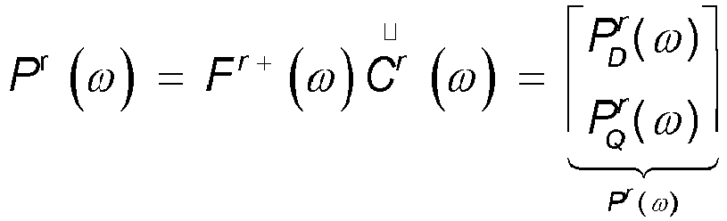
- where F r+ (ω) is a Moore-Penrose pseudo-inverse of Fr (ω).
- In the vectorthe first element is the direct sound power spectrum


- Finally, the direct sound powers at all frequency points are added up, to obtain the direct sound energy of the voice signal, that is:

- It should be noted that the example of obtaining a direct sound energy is described in detail above for an electronic device r. A calculation process of a direct sound energy of any other electronic device is similar, which therefore will not be repeated herein. In other words, through the above operations, a plurality of direct sound energies corresponding to the plurality of electronic devices one by one can be respectively obtained.
- In some embodiments, selecting, from the determined plurality of direct sound energies, at least one direct sound energy satisfying a predetermined condition includes: from the plurality of electronic devices, selecting a direct sound energy with a highest direct sound energy, or selecting a direct sound energy exceeding a preset threshold.
- In embodiments of the present disclosure, a plurality of electronic devices may be regarded as a distributed sound pickup decision system. According to the method for responding herein, at least one electronic device may be determined from the distributed sound pickup decision system to respond to the user's voice command. In an example, selecting an electronic device with a highest direct sound energy from the plurality of electronic devices may be implemented by one designated electronic device of the plurality of electronic devices, and the other electronic devices transmit direct sound energy received by themselves associated with the voice signal to the designated electronic device, then the designated electronic device selects the largest direct sound energy from the direct sound energy received by itself and the direct sound energies received from the other electronic devices, and indicates the electronic device corresponding to the largest direct sound energy to respond. In another example, any two of the plurality of electronic devices may be compared with each other, and an electronic device having a larger direct sound energy is compared with other electronic devices until the largest direct sound energy is determined.
- In the method for responding to a voice signal according to embodiments of the present disclosure, by processing a voice signal acquired by a plurality of electronic devices in real time, and determining the direct sound energy of each of the electronic devices for the voice signal, it can perform an accurate and effective sound pickup decision according to the direct sound energies, to select at least one electronic device satisfying a predetermined condition from the plurality of electronic devices. Thereby, it realizes a sound pickup decision system based on a plurality of electronic devices, which can make more accurate, more reasonable, and more targeted response to the user's voice, improving voice interaction experience.
-
FIG. 2 is a block diagram of asystem 200 for responding to a voice signal according to an exemplary embodiment. As shownFIG. 2 , thesystem 200 includes: - a
receiving module 201 configured to receive a voice signal through a plurality of electronic devices to; - a first determining
module 202 configured to, for each of the electronic devices, determine a target sound source point associated with the voice signal; - a second determining
module 203 configured to, for each of the electronic devices, determine a direct sound energy associated with the voice signal according to the target sound source point; and
aresponse module 204 configured to select at least one electronic device with a direct sound energy satisfying a predetermined condition from the plurality of electronic devices, and respond to the voice signal through the at least one electronic device. - Specific configurations and operations of the various modules of the
system 200 for responding to a voice signal have been described in detail above with reference to the method for responding to a voice signal illustrated inFIG. 1 , and will not be repeated herein. - The various device components, circuits, modules, units, blocks, or portions may have modular configurations, or are composed of discrete components, but nonetheless may be referred to as "modules" or "portions" in general. In other words, the "components," "circuits," "modules," "units," "blocks," or "portions" referred to herein may or may not be in modular forms.
-
FIG. 3 is a flow chart of a method for responding to a voice signal according to an exemplary embodiment, the method for responding to a voice signal being performed by any one electronic device. As shown inFIG. 3 , the method for responding to a voice signal includes the following operations. - In operation S31, a voice signal is received by the electronic device.
- In operation S32, a target sound source point associated with the voice signal is determined.
- In operation S33, a direct sound energy associated with the voice signal is determined according to the target sound source point.
- In operation S34, when the direct sound energy satisfies a predetermined condition, the electronic device responds to the voice signal.
- The method for responding to a voice signal performed by a single electronic device is similar to the related configurations and operations in the corresponding operations of the method for responding to a voice signal of the plurality of electronic devices described above with reference to
FIG. 1 , and will not be repeated here. -
FIG. 4 is a block diagram of anelectronic device 400 for responding to a voice signal according to an exemplary embodiment. As shownFIG. 4 , theelectronic device 400 includes: a receivingportion 401, a first determining portion 402, a second determining portion 403 and a respondingportion 404. - The receiving
portion 401 is configured to cause the electronic device to receive a voice signal. - The first determining portion 402 is configured to determine a target sound source point associated with the voice signal.
- The second determining portion 403 is configured to determine a direct sound energy associated with the voice signal according to the target sound source point.
- The responding
portion 404 is configured to respond to the voice signal when the direct sound energy satisfies a predetermined condition. -
FIG. 5 is a block diagram of anelectronic device 500 for responding to a voice signal according to an exemplary embodiment. Referring toFIG. 5 , theelectronic device 500 includes anarray 501 of sound acquisition devices, aprocessor 502 and amemory 503. - The
array 501 of sound acquisition devices is configured to receive a voice signal. - The
memory 503 is configured to store instructions executable by theprocessor 502. - The
processor 502 is configured to perform the method for responding to a voice signal as shown inFIG. 3 . -
FIG. 6 is a block diagram of anelectronic device 600 according to an exemplary embodiment. For example, theelectronic device 600 may be a mobile phone, a computer, a digital broadcast terminal, a message receiving and sending device, a game console, a tablet device, a medical device, a fitness device, a personal digital assistant, and the like. - Referring to
FIG. 6 , theelectronic device 600 may include one or more of the following components: aprocessing component 602, amemory 604, apower component 606, amultimedia component 608, anaudio component 610, an input/output (I/O)interface 612, asensor component 614, and acommunication component 616. - The
processing component 602 typically controls overall operations of theelectronic device 600, such as operations associated with display, phone call, data communications, camera operations and operations associated with recording operations. Theprocessing component 602 may include one ormore processors 620 to execute instructions, to perform all or part of the operations of the above method. Moreover, theprocessing component 602 may include one or more modules which facilitate interactions between theprocessing component 602 and other components. For instance, theprocessing component 602 may include a multimedia module to facilitate an interaction between themultimedia component 608 and theprocessing component 602. - The
memory 604 is configured to store various types of data to support operations on theelectronic device 600. Examples of such data include instructions for any applications or methods operated on theelectronic device 600, contact data, telephone directory data, messages, pictures, video, etc. Thememory 604 may be implemented using any type of volatile or non-volatile memory devices, or a combination thereof, such as a Static Random Access Memory (SRAM), an Electrically Erasable Programmable Read-Only Memory (EEPROM), an Erasable Programmable Read-Only Memory (EPROM), a Programmable Read-Only Memory (PROM), a Read-Only Memory (ROM), a magnetic memory, a flash memory, a magnetic or optical disk. - The
power component 606 provides power to various components of theelectronic device 600. Thepower component 606 may include a power management system, one or more power sources, and any other components associated with generation, management, and distribution of power for theelectronic device 600. - The
multimedia component 608 includes a screen providing an output interface between theelectronic device 600 and the user. In some embodiments, the screen may include a Liquid Crystal Display (LCD) and a Touch Panel (TP). In some embodiments, an Organic Light-Emitting Diode (OLED) or other types of display screens can be adopted. - If the screen includes a touch panel, the screen may be implemented as a touch screen to receive input signals from the user. The touch panel includes one or more touch sensors to sense touches, swipes, and gestures on the touch panel. The touch sensors may not only sense a boundary of a touch or swipe action, but also sense a period of time and a pressure associated with the touch or swipe action. In some embodiments, the
multimedia component 608 includes a front camera and/or a rear camera. When thedevice 600 is in an operation mode, such as a shooting mode or a video mode, the front camera and/or the rear camera may receive external multimedia data. Each front and rear camera may be a fixed optical lens system or have a focal length and a capability of optical zoom. - The
audio component 610 is configured to output and/or input audio signals. For example, theaudio component 610 includes a microphone ("MIC") configured to receive an external audio signal when theelectronic device 600 is in an operation mode, such as a call mode, a recording mode and a voice recognition mode. The received audio signal may be further stored in thememory 604 or transmitted via thecommunication component 616. In some embodiments, theaudio component 610 further includes a loudspeaker to output audio signals. - The I/
O interface 612 provides an interface between theprocessing component 602 and peripheral interface modules, such as a keyboard, a click wheel, buttons, and the like. These buttons may include, but are not limited to, a home button, a volume button, a start button, and a lock button. - The
sensor component 614 includes one or more sensors to provide status assessments of various aspects of theelectronic device 600. For instance, thesensor component 614 may detect an on/off status of theelectronic device 600, relative positioning of components, such as a display and a keypad of theelectronic device 600, a change in position of theelectronic device 600 or a component of theelectronic device 600, a presence or absence of user's contact with theelectronic device 600, an orientation or an acceleration/deceleration of theelectronic device 600, and a change in temperature of theelectronic device 600. Thesensor component 614 may include a proximity sensor configured to detect presence of nearby objects without any physical contact. Thesensor component 614 may also include an optical sensor, such as a CMOS or CCD image sensor, for use in imaging applications. In some embodiments, thesensor component 614 may also include an accelerometer sensor, a gyroscope sensor, a magnetic sensor, a pressure sensor, or a temperature sensor. - The
communication component 616 is configured to facilitate communication, wired or wirelessly, between theelectronic device 600 and other devices. Theelectronic device 600 can access a wireless network based on a communication standard, such as WiFi, 2G, 3G, 4G or 5G, or a combination thereof. In one exemplary embodiment, thecommunication component 616 receives a broadcast signal or broadcast associated information from an external broadcast management system via a broadcast channel. In one exemplary embodiment, thecommunication component 616 further includes a Near Field Communication (NFC) module to facilitate short-range communications. For example, the NFC module may be implemented based on a Radio Frequency IDentification (RFID) technology, an Infrared Data Association (IrDA) technology, an Ultra-WideBand (UWB) technology, a BlueTooth (BT) technology, and other technologies. - In exemplary embodiments, the
electronic device 600 may be implemented with one or more Application Specific Integrated Circuits (ASICs), Digital Signal Processors (DSPs), Digital Signal Processing Devices (DSPDs), Programmable Logic Devices (PLDs), Field Programmable Gate Arrays (FPGAs), controllers, micro-controllers, microprocessors, or other electronic components, to perform the above method. - In exemplary embodiments, there is also provided a non-transitory computer-readable storage medium including instructions, such as the
memory 604 including instructions, the above instructions executable by theprocessor 620 in theelectronic device 600 to perform the above method. For example, the non-transitory computer-readable storage medium may be a ROM, a Random Access Memory (RAM), a CD-ROM, a magnetic tape, a floppy disc, an optical data storage device, and the like. - An embodiment of the present disclosure also provides a non-transitory computer readable storage medium, when the instructions in the storage medium are executed by the processor of the electronic device, the electronic device is caused to perform the method for responding to a voice signal as shown in
FIG. 3 . - An embodiment of the present disclosure also provides a sound pickup decision system for responding to a voice signal. The sound pickup decision system may perform the method for responding to a voice signal described with reference to
FIG. 1 . In some embodiments, the sound pickup decision system may be composed of a plurality of electronic devices as shown inFIG. 4 . Alternatively, the sound pickup decision system may be composed of the plurality of electronic devices as shown inFIG. 5 . - In the sound pickup decision system of the embodiment of the present disclosure, by processing a voice signal acquired by a plurality of electronic devices in real time, and determining a direct sound energy of each of the electronic devices relative to the voice signal, it can perform accurate and effective sound pickup decisions according to the direct sound energies, to select at least one electronic device satisfying a predetermined condition from the plurality of electronic devices. Thereby, it can make more accurate, more reasonable, and more targeted response to the user's voice, improving voice interaction experience.
- The terms "first" and "second" are used for descriptive purposes only and are not to be construed as indicating or implying a relative importance or implicitly indicating the number of technical features indicated. Thus, elements referred to as "first" and "second" can include one or more of the features either explicitly or implicitly. In the description of the present disclosure, "a plurality" indicates two or more unless specifically defined otherwise.
- In the description of the present disclosure, the terms "one embodiment," "some embodiments," "example," "specific example," or "some examples," and the like can indicate a specific feature described in connection with the embodiment or example, a structure, a material or feature included in at least one embodiment or example. In the present disclosure, the schematic representation of the above terms is not necessarily directed to the same embodiment or example.
- Moreover, the particular features, structures, materials, or characteristics described can be combined in a suitable manner in any one or more embodiments or examples. In addition, various embodiments or examples described in the specification, as well as features of various embodiments or examples, can be combined and reorganized,
- In some embodiments, the control and/or interface software or app can be provided in a form of a non-transitory computer-readable storage medium having instructions stored thereon . For example, the non-transitory computer-readable storage medium can be a ROM, a CD-ROM, a magnetic tape, a floppy disk, optical data storage equipment, a flash drive such as a USB drive or an SD card, and the like.
- Implementations of the subject matter and the operations described in this disclosure can be implemented in digital electronic circuitry, or in computer software, firmware, or hardware, including the structures disclosed herein and their structural equivalents, or in combinations of one or more of them. Implementations of the subject matter described in this disclosure can be implemented as one or more computer programs, i.e., one or more portions of computer program instructions, encoded on one or more computer storage mediums for execution by, or to control the operation of, data processing apparatus.
- Alternatively, or in addition, the program instructions can be encoded on an artificially-generated propagated signal, e.g., a machine-generated electrical, optical, or electromagnetic signal, which is generated to encode information for transmission to suitable receiver apparatus for execution by a data processing apparatus. A computer storage medium can be, or be included in, a computer-readable storage device, a computer-readable storage substrate, a random or serial access memory array or device, or a combination of one or more of them.
- Moreover, while a computer storage medium is not a propagated signal, a computer storage medium can be a source or destination of computer program instructions encoded in an artificially-generated propagated signal. The computer storage medium can also be, or be included in, one or more separate components or media (e.g., multiple CDs, disks, drives, or other storage devices). Accordingly, the computer storage medium can be tangible.
- The operations described in this disclosure can be implemented as operations performed by a data processing apparatus on data stored on one or more computer-readable storage devices or received from other sources.
- The devices in this disclosure can include special purpose logic circuitry, e.g., an FPGA (field-programmable gate array), or an ASIC (application-specific integrated circuit). The device can also include, in addition to hardware, code that creates an execution environment for the computer program in question, e.g., code that constitutes processor firmware, a protocol stack, a database management system, an operating system, a cross-platform runtime environment, a virtual machine, or a combination of one or more of them. The devices and execution environment can realize various different computing model infrastructures, such as web services, distributed computing, and grid computing infrastructures.
- A computer program (also known as a program, software, software application, app, script, or code) can be written in any form of programming language, including compiled or interpreted languages, declarative or procedural languages, and it can be deployed in any form, including as a stand-alone program or as a portion, component, subroutine, object, or other portion suitable for use in a computing environment. A computer program can, but need not, correspond to a file in a file system. A program can be stored in a portion of a file that holds other programs or data (e.g., one or more scripts stored in a markup language document), in a single file dedicated to the program in question, or in multiple coordinated files (e.g., files that store one or more portions, sub-programs, or portions of code). A computer program can be deployed to be executed on one computer or on multiple computers that are located at one site or distributed across multiple sites and interconnected by a communication network.
- The processes and logic flows described in this disclosure can be performed by one or more programmable processors executing one or more computer programs to perform actions by operating on input data and generating output. The processes and logic flows can also be performed by, and apparatus can also be implemented as, special purpose logic circuitry, e.g., an FPGA, or an ASIC.
- Processors or processing circuits suitable for the execution of a computer program include, by way of example, both general and special purpose microprocessors, and any one or more processors of any kind of digital computer. Generally, a processor will receive instructions and data from a read-only memory, or a random-access memory, or both. Elements of a computer can include a processor configured to perform actions in accordance with instructions and one or more memory devices for storing instructions and data.
- Generally, a computer will also include, or be operatively coupled to receive data from and/or transfer data to, one or more mass storage devices for storing data, e.g., magnetic, magneto-optical disks, or optical disks. However, a computer need not have such devices. Moreover, a computer can be embedded in another device, e.g., a mobile telephone, a personal digital assistant (PDA), a mobile audio or video player, a game console, a Global Positioning System (GPS) receiver, or a portable storage device (e.g., a universal serial bus (USB) flash drive), to name just a few.
- Devices suitable for storing computer program instructions and data include all forms of non-volatile memory, media and memory devices, including by way of example semiconductor memory devices, e.g., EPROM, EEPROM, and flash memory devices; magnetic disks, e.g., internal hard disks or removable disks; magneto-optical disks; and CD-ROM and DVD-ROM disks. The processor and the memory can be supplemented by, or incorporated in, special purpose logic circuitry.
- To provide for interaction with a user, implementations of the subject matter described in this specification can be implemented with a computer and/or a display device, e.g., a VR/AR device, a head-mount display (HMD) device, a head-up display (HUD) device, smart eyewear (e.g., glasses), a CRT (cathode-ray tube), LCD (liquid-crystal display), OLED (organic light emitting diode), TFT (thin-film transistor), plasma, other flexible configuration, or any other monitor for displaying information to the user and a keyboard, a pointing device, e.g., a mouse, trackball, etc., or a touch screen, touch pad, etc., by which the user can provide input to the computer.
- Implementations of the subject matter described in this specification can be implemented in a computing system that includes a back-end component, e.g., as a data server, or that includes a middleware component, e.g., an application server, or that includes a front-end component, e.g., a client computer having a graphical user interface or a Web browser through which a user can interact with an implementation of the subject matter described in this specification, or any combination of one or more such back-end, middleware, or front-end components.
- The components of the system can be interconnected by any form or medium of digital data communication, e.g., a communication network. Examples of communication networks include a local area network ("LAN") and a wide area network ("WAN"), an inter-network (e.g., the Internet), and peer-to-peer networks (e.g., ad hoc peer-to-peer networks).
- While this specification contains many specific implementation details, these should not be construed as limitations on the scope of any claims, but rather as descriptions of features specific to particular implementations. Certain features that are described in this specification in the context of separate implementations can also be implemented in combination in a single implementation. Conversely, various features that are described in the context of a single implementation can also be implemented in multiple implementations separately or in any suitable sub-combination.
- Moreover, although features can be described above as acting in certain combinations and even initially claimed as such, one or more features from a claimed combination can in some cases be excised from the combination, and the claimed combination can be directed to a sub-combination or variation of a sub-combination.
- Similarly, while operations are depicted in the drawings in a particular order, this should not be understood as requiring that such operations be performed in the particular order shown or in sequential order, or that all illustrated operations be performed, to achieve desirable results. In certain circumstances, multitasking and parallel processing can be advantageous. Moreover, the separation of various system components in the implementations described above should not be understood as requiring such separation in all implementations, and it should be understood that the described program components and systems can generally be integrated together in a single software product or packaged into multiple software products.
- As such, particular implementations of the subject matter have been described. Other implementations are within the scope of the following claims. In some cases, the actions recited in the claims can be performed in a different order and still achieve desirable results. In addition, the processes depicted in the accompanying figures do not necessarily require the particular order shown, or sequential order, to achieve desirable results. In certain implementations, multitasking or parallel processing can be utilized.
- It is intended that the specification and embodiments be considered as examples only. Other embodiments of the disclosure will be apparent to those skilled in the art in view of the specification and drawings of the present disclosure. That is, although specific embodiments have been described above in detail, the description is merely for purposes of illustration. It should be appreciated, therefore, that many aspects described above are not intended as required or essential elements unless explicitly stated otherwise.
- Various modifications of the disclosed aspects of the example embodiments, in addition to those described above, can be made by a person of ordinary skill in the art, having the benefit of the present disclosure, without departing from the scope of the disclosure defined in the following claims.
- It is to be understood that "multiple" mentioned in the present disclosure refers to two or more than two. "And/or" describes an association relationship of associated objects and represent that three relationships can exist. For example, A and/or B can represent three conditions, i.e., independent existence of A, coexistence of A and B and independent existence of B. Character "/" usually represents that previous and next associated objects form an "or" relationship.
Claims (14)
- A method for responding to a voice signal, applied to a plurality of electronic devices, comprising:receiving (S11), by the plurality of electronic devices, a voice signal;determining (S12), for each of the electronic devices, a target sound source point associated with the voice signal;determining (S13), for each of the electronic devices, a direct sound energy associated with the voice signal according to the target sound source point; andselecting (S14), from the plurality of electronic devices, at least one electronic device with a direct sound energy satisfying a predetermined condition, and responding, by the at least one electronic device, to the voice signal;wherein determining (S13) the direct sound energy associated with the voice signal according to the target sound source point comprises:determining, based on the target sound source point, a direct sound coefficient and a reverberation coefficient;establishing a direct sound model based on the direct sound coefficient, and establishing a reverberation model based on the reverberation coefficient;establishing a spatial covariance matrix based on the direct sound model and the reverberation model; anddetermining the direct sound energy based on the spatial covariance matrix.
- The method for responding to a voice signal according to claim 1, wherein determining (S12) the target sound source point associated with the voice signal comprises:selecting, based on a geometric center of an array of sound acquisition devices comprised in each of the electronic devices, a plurality of candidate sound source points of the each of the electronic devices;determining a total correlation of each candidate sound source point of the each of the electronic devices relative to the voice signal; anddetermining a candidate sound source point with a largest total correlation as the target sound source point of the electronic device.
- The method for responding to a voice signal according to claim 2, wherein determining the total correlation of the each candidate sound source point of the each of the electronic devices relative to the voice signal comprises:determining, for the each candidate sound source point, a correlation between every two sound acquisition devices in the array of sound acquisition devices relative to the voice signal at the candidate sound source point; andcalculating a sum of correlations determined for the array of sound acquisition devices, as the total correlation of the candidate sound source point.
- The method for responding to a voice signal according to claim 3, wherein, determining, for the each candidate sound source point, the correlation between the every two sound acquisition devices in the array of sound acquisition devices relative to the voice signal at the candidate sound source point comprises:determining, according to positions of the every two sound acquisition devices and a position of the candidate sound source point, a delay difference between the two sound acquisition devices respectively relative to the candidate sound source point; anddetermining, according to the delay difference and a frequency domain representation of the voice signal, the correlation between the two every sound acquisition devices on the voice signal at the candidate sound source point.
- The method for responding to a voice signal according to claim 1, wherein determining the direct sound energy based on the spatial covariance matrix comprises:determining a sum of the direct sound model and the reverberation model as the spatial covariance matrix;determining, based on the spatial covariance matrix and a frequency domain representation of the voice signal, a direct sound power spectrum; anddetermining the direct sound energy based on the direct sound power spectrum.
- The method for responding to a voice signal according to any preceding claim , wherein selecting (S14), from the plurality of electronic devices, at least one electronic device with the direct sound energy satisfying the predetermined condition comprises:
selecting, from the plurality of electronic devices, at least one electronic device with a largest direct sound energy, or selecting, from the plurality of electronic devices, at least one electronic device with a direct sound energy exceeding a predetermined threshold. - A system for responding to a voice signal, comprising:a receiving module (201) configured to receive a voice signal through a plurality of electronic devices;a first determining module (202) configured to, for each of the electronic devices, determine a target sound source point associated with the voice signal;a second determining module (203) configured, for each of the electronic devices, to determine (S 13) a direct sound energy associated with the voice signal according to the target sound source point; anda response module (204) configured to select, from the plurality of electronic devices, at least one electronic device with a direct sound energy satisfying a predetermined condition, and respond, through the at least one electronic device, to the voice signal;wherein the determination (S 13) of a direct sound energy associated with the voice signal according to the target sound source point includes:determining, based on the target sound source point, a direct sound coefficient and a reverberation coefficient;establishing a direct sound model based on the direct sound coefficient, and establishing a reverberation model based on the reverberation coefficient;establishing a spatial covariance matrix based on the direct sound model and the reverberation model; anddetermining the direct sound energy based on the spatial covariance matrix.
- A method for responding to a voice signal, comprising:receiving (S31), by an electronic device, a voice signal;determining (S32), by the electronic device, a target sound source point associated with the voice signal;determining (S33), by the electronic device, a direct sound energy associated with the voice signal according to the target sound source point; andresponding (S34), by the electronic device, to the voice signal when the direct sound energy satisfies a predetermined condition;wherein said determining (S33) of a direct sound energy associated with the voice signal according to the target sound source point includes:determining, based on the target sound source point, a direct sound coefficient and a reverberation coefficient;establishing a direct sound model based on the direct sound coefficient, and establishing a reverberation model based on the reverberation coefficient;establishing a spatial covariance matrix based on the direct sound model and the reverberation model; anddetermining the direct sound energy based on the spatial covariance matrix.
- An electronic device for responding to a voice signal, comprising:a receiving portion (401) configured to receive a voice signal;a first determining portion (402) configured to determine a target sound source point associated with the voice signal;a second determining portion (403) configured to determine a direct sound energy associated with the voice signal according to the target sound source point; anda responding portion (404) configured to respond to the voice signal when the direct sound energy satisfies a predetermined condition;wherein the determination, by the second determining portion (403), of a direct sound energy associated with the voice signal according to the target sound source points includes:determining, based on the target sound source point, a direct sound coefficient and a reverberation coefficient;establishing a direct sound model based on the direct sound coefficient, and establishing a reverberation model based on the reverberation coefficient;establishing a spatial covariance matrix based on the direct sound model and the reverberation model; anddetermining the direct sound energy based on the spatial covariance matrix.
- The electronic device of claim 9, wherein the receiving portion comprises
an array of sound acquisition devices (501). - A non-transitory computer readable storage medium, wherein when instructions in the storage medium are executed by a processor of an electronic device, the electronic device is caused to execute the method for responding to a voice signal according to claim 8.
- The system of claim 7, wherein the system comprises a plurality of electronic devices, and wherein the plurality of electronic devices simultaneously receive a voice signal.
- A system for responding to a voice signal, wherein the system comprises a plurality of electronic devices according to claim 9, or comprises a plurality of electronic devices according to claim 10.
- A computer program, when being executed on a processor of an electronic device, performs a method for responding to a voice signal according to any one of claims 1-6.
Applications Claiming Priority (1)
| Application Number | Priority Date | Filing Date | Title |
|---|---|---|---|
| CN201910780342.2A CN110364161A (en) | 2019-08-22 | 2019-08-22 | Method, electronic equipment, medium and the system of voice responsive signal |
Publications (2)
| Publication Number | Publication Date |
|---|---|
| EP3783604A1 EP3783604A1 (en) | 2021-02-24 |
| EP3783604B1 true EP3783604B1 (en) | 2024-03-27 |
Family
ID=68225136
Family Applications (1)
| Application Number | Title | Priority Date | Filing Date |
|---|---|---|---|
| EP19218255.8A Active EP3783604B1 (en) | 2019-08-22 | 2019-12-19 | Method for responding to voice signal, electronic device, medium and system |
Country Status (3)
| Country | Link |
|---|---|
| US (1) | US11295740B2 (en) |
| EP (1) | EP3783604B1 (en) |
| CN (1) | CN110364161A (en) |
Families Citing this family (14)
| Publication number | Priority date | Publication date | Assignee | Title |
|---|---|---|---|---|
| CN110687815B (en) * | 2019-10-29 | 2023-07-14 | 北京小米智能科技有限公司 | Equipment control method, device, terminal equipment and storage medium |
| CN110827818B (en) * | 2019-11-20 | 2024-04-09 | 腾讯科技(深圳)有限公司 | A control method, device, equipment and storage medium of intelligent voice equipment |
| CN111312239B (en) * | 2020-01-20 | 2023-09-26 | 北京小米松果电子有限公司 | Response method, response device, electronic equipment and storage medium |
| CN111417053B (en) * | 2020-03-10 | 2023-07-25 | 北京小米松果电子有限公司 | Sound pickup volume control method, sound pickup volume control device and storage medium |
| CN111933170B (en) * | 2020-07-20 | 2024-03-29 | 歌尔科技有限公司 | Voice signal processing method, device, equipment and storage medium |
| CN112002341B (en) * | 2020-08-21 | 2023-06-09 | 南京工程学院 | Method for parameterized representation, encrypted transmission and reconstruction of speech signals |
| CN112599126B (en) * | 2020-12-03 | 2022-05-27 | 海信视像科技股份有限公司 | Awakening method of intelligent device, intelligent device and computing device |
| CN115482811A (en) * | 2021-05-31 | 2022-12-16 | 华为技术有限公司 | Voice interaction response method and electronic equipment |
| CN113674761B (en) * | 2021-07-26 | 2023-07-21 | 青岛海尔科技有限公司 | Equipment identification method and equipment identification system |
| CN113707165B (en) * | 2021-09-07 | 2024-09-17 | 联想(北京)有限公司 | Audio processing method and device, electronic equipment and storage medium |
| CN113851124A (en) * | 2021-09-09 | 2021-12-28 | 青岛海尔空调器有限总公司 | Method and apparatus for controlling home appliance, and storage medium |
| CN115019795B (en) * | 2022-05-31 | 2025-08-26 | 四川虹美智能科技有限公司 | Method, device and voice device for distributed voice equipment participating in elections |
| CN114879527B (en) * | 2022-05-31 | 2023-06-27 | 四川虹美智能科技有限公司 | Intelligent household appliance control method and device based on intelligent grouping and skill matching |
| CN114898750B (en) * | 2022-05-31 | 2023-05-16 | 四川虹美智能科技有限公司 | Smart home appliance control method, device, system, and equipment based on collaborative response |
Family Cites Families (41)
| Publication number | Priority date | Publication date | Assignee | Title |
|---|---|---|---|---|
| US5561737A (en) * | 1994-05-09 | 1996-10-01 | Lucent Technologies Inc. | Voice actuated switching system |
| US6826284B1 (en) * | 2000-02-04 | 2004-11-30 | Agere Systems Inc. | Method and apparatus for passive acoustic source localization for video camera steering applications |
| KR100959983B1 (en) * | 2005-08-11 | 2010-05-27 | 아사히 가세이 가부시키가이샤 | Sound source separating device, speech recognition device, mobile phone, sound source separating method, and program |
| DE602007004061D1 (en) * | 2007-02-06 | 2010-02-11 | Oticon As | Estimation of own voice activity with a hearing aid system based on the relationship between direct sound and echo |
| KR101449433B1 (en) * | 2007-11-30 | 2014-10-13 | 삼성전자주식회사 | Noise cancelling method and apparatus from the sound signal through the microphone |
| CN101510426B (en) * | 2009-03-23 | 2013-03-27 | 北京中星微电子有限公司 | Method and system for eliminating noise |
| JP5516060B2 (en) * | 2009-05-19 | 2014-06-11 | ヤマハ株式会社 | Sound field control device |
| US8861756B2 (en) * | 2010-09-24 | 2014-10-14 | LI Creative Technologies, Inc. | Microphone array system |
| KR20130048075A (en) * | 2011-11-01 | 2013-05-09 | 삼성전자주식회사 | Apparatus for multiple sound source localization and method the same |
| EP2600637A1 (en) * | 2011-12-02 | 2013-06-05 | Fraunhofer-Gesellschaft zur Förderung der angewandten Forschung e.V. | Apparatus and method for microphone positioning based on a spatial power density |
| JP5635024B2 (en) * | 2012-02-24 | 2014-12-03 | 日本電信電話株式会社 | Acoustic signal emphasizing device, perspective determination device, method and program thereof |
| CN102750956B (en) * | 2012-06-18 | 2014-07-16 | 歌尔声学股份有限公司 | Method and device for removing reverberation of single channel voice |
| US9812126B2 (en) * | 2014-11-28 | 2017-11-07 | Microsoft Technology Licensing, Llc | Device arbitration for listening devices |
| US10026399B2 (en) * | 2015-09-11 | 2018-07-17 | Amazon Technologies, Inc. | Arbitration between voice-enabled devices |
| US9875081B2 (en) * | 2015-09-21 | 2018-01-23 | Amazon Technologies, Inc. | Device selection for providing a response |
| US9640197B1 (en) * | 2016-03-22 | 2017-05-02 | International Business Machines Corporation | Extraction of target speeches |
| CN110058834B (en) * | 2016-06-11 | 2022-06-17 | 苹果公司 | Intelligent device arbitration and control |
| CN106898348B (en) * | 2016-12-29 | 2020-02-07 | 北京小鸟听听科技有限公司 | Dereverberation control method and device for sound production equipment |
| WO2018127450A1 (en) * | 2017-01-03 | 2018-07-12 | Koninklijke Philips N.V. | Audio capture using beamforming |
| US10621980B2 (en) | 2017-03-21 | 2020-04-14 | Harman International Industries, Inc. | Execution of voice commands in a multi-device system |
| CN107705785A (en) * | 2017-08-01 | 2018-02-16 | 百度在线网络技术(北京)有限公司 | Sound localization method, intelligent sound box and the computer-readable medium of intelligent sound box |
| JP6513749B2 (en) | 2017-08-09 | 2019-05-15 | レノボ・シンガポール・プライベート・リミテッド | Voice assist system, server device, voice assist method thereof, and program for execution by computer |
| EP3467819B1 (en) * | 2017-10-05 | 2024-06-12 | Harman Becker Automotive Systems GmbH | Apparatus and method using multiple voice command devices |
| CN107689904A (en) * | 2017-10-23 | 2018-02-13 | 深圳市敢为软件技术有限公司 | Sound control method, device, Internet of things system and readable storage medium storing program for executing |
| US10374816B1 (en) * | 2017-12-13 | 2019-08-06 | Amazon Technologies, Inc. | Network conference management and arbitration via voice-capturing devices |
| CN108318862B (en) * | 2017-12-26 | 2021-08-20 | 北京大学 | A method of sound source localization based on neural network |
| CN110097877A (en) * | 2018-01-29 | 2019-08-06 | 阿里巴巴集团控股有限公司 | The method and apparatus of authority recognition |
| US10885907B2 (en) * | 2018-02-14 | 2021-01-05 | Cirrus Logic, Inc. | Noise reduction system and method for audio device with multiple microphones |
| US10685652B1 (en) * | 2018-03-22 | 2020-06-16 | Amazon Technologies, Inc. | Determining device groups |
| CN108206023A (en) * | 2018-04-10 | 2018-06-26 | 南京地平线机器人技术有限公司 | Sound processing apparatus and sound processing method |
| CN108962263B (en) | 2018-06-04 | 2019-09-20 | 百度在线网络技术(北京)有限公司 | A kind of smart machine control method and system |
| US10667072B2 (en) * | 2018-06-12 | 2020-05-26 | Magic Leap, Inc. | Efficient rendering of virtual soundfields |
| CN109347709B (en) * | 2018-10-26 | 2021-02-23 | 北京蓦然认知科技有限公司 | Intelligent equipment control method, device and system |
| CN109509468B (en) * | 2018-11-01 | 2021-03-16 | 珠海格力电器股份有限公司 | Method and device for equipment to execute voice broadcast task |
| CN109599104B (en) * | 2018-11-20 | 2022-04-01 | 北京小米智能科技有限公司 | Multi-beam selection method and device |
| CN109658927A (en) * | 2018-11-30 | 2019-04-19 | 北京小米移动软件有限公司 | Wake-up processing method, device and the management equipment of smart machine |
| CN109917663B (en) * | 2019-03-25 | 2022-02-15 | 北京小米移动软件有限公司 | Method and device for controlling equipment |
| CN110072177B (en) * | 2019-04-30 | 2022-04-08 | 北京小米智能科技有限公司 | Space division information acquisition method and device and storage medium |
| CN110085235A (en) * | 2019-05-05 | 2019-08-02 | 珠海格力电器股份有限公司 | voice control method and device |
| US11082460B2 (en) * | 2019-06-27 | 2021-08-03 | Synaptics Incorporated | Audio source enhancement facilitated using video data |
| US10735887B1 (en) * | 2019-09-19 | 2020-08-04 | Wave Sciences, LLC | Spatial audio array processing system and method |
-
2019
- 2019-08-22 CN CN201910780342.2A patent/CN110364161A/en active Pending
- 2019-11-29 US US16/699,186 patent/US11295740B2/en active Active
- 2019-12-19 EP EP19218255.8A patent/EP3783604B1/en active Active
Also Published As
| Publication number | Publication date |
|---|---|
| CN110364161A (en) | 2019-10-22 |
| EP3783604A1 (en) | 2021-02-24 |
| US11295740B2 (en) | 2022-04-05 |
| US20210056965A1 (en) | 2021-02-25 |
Similar Documents
| Publication | Publication Date | Title |
|---|---|---|
| US11295740B2 (en) | Voice signal response method, electronic device, storage medium and system | |
| US12174603B2 (en) | Equipment control method, equipment control apparatus and storage medium | |
| US11568868B2 (en) | Voice control method and apparatus, and computer storage medium | |
| US10362438B2 (en) | Portable apparatus and method of controlling location information of portable apparatus | |
| KR102639229B1 (en) | Virtual assistant identification of nearby computing devices | |
| KR102515013B1 (en) | Controlling electronic devices and displaying information based on wireless ranging | |
| CN111696570B (en) | Voice signal processing method, device, equipment and storage medium | |
| EP3709607B1 (en) | Device and method for adaptively changing task-performing subjects | |
| US11205411B2 (en) | Audio signal processing method and device, terminal and storage medium | |
| US11797584B2 (en) | Method, electronic device, and computer-readable storage medium for determining answer to question of product | |
| US10789969B1 (en) | Audio signal noise estimation method and device, and storage medium | |
| US20210050010A1 (en) | Audio processing method and apparatus, and storage medium | |
| US11695301B2 (en) | Wireless charging method and device, foldable-screen electronic device and storage medium | |
| US20210182015A1 (en) | Audio playing control method and device and storage medium | |
| EP3657497A1 (en) | Method and device for selecting target beam data from a plurality of beams | |
| US20210306784A1 (en) | Audio field adjusting method and apparatus | |
| US11368739B2 (en) | Method and apparatus for inputting information on display interface, and storage medium | |
| CN110147742A (en) | A key point positioning method, device and terminal | |
| US10945071B1 (en) | Sound collecting method, device and medium | |
| US11158085B2 (en) | Method, apparatus and medium for object tracking | |
| EP3889913A1 (en) | Animation generation | |
| US11217267B2 (en) | Electronic device for identifying location information of external device and operating method thereof | |
| US20140273986A1 (en) | Service aware software architecture in wireless device ecosystem | |
| US11778086B2 (en) | Inter-device interactive control method, apparatus, and storage medium | |
| CN114023323A (en) | Switching method, device, terminal and storage medium |
Legal Events
| Date | Code | Title | Description |
|---|---|---|---|
| PUAI | Public reference made under article 153(3) epc to a published international application that has entered the european phase |
Free format text: ORIGINAL CODE: 0009012 |
|
| STAA | Information on the status of an ep patent application or granted ep patent |
Free format text: STATUS: REQUEST FOR EXAMINATION WAS MADE |
|
| 17P | Request for examination filed |
Effective date: 20201109 |
|
| AK | Designated contracting states |
Kind code of ref document: A1 Designated state(s): AL AT BE BG CH CY CZ DE DK EE ES FI FR GB GR HR HU IE IS IT LI LT LU LV MC MK MT NL NO PL PT RO RS SE SI SK SM TR |
|
| AX | Request for extension of the european patent |
Extension state: BA ME |
|
| STAA | Information on the status of an ep patent application or granted ep patent |
Free format text: STATUS: EXAMINATION IS IN PROGRESS |
|
| 17Q | First examination report despatched |
Effective date: 20220114 |
|
| GRAP | Despatch of communication of intention to grant a patent |
Free format text: ORIGINAL CODE: EPIDOSNIGR1 |
|
| STAA | Information on the status of an ep patent application or granted ep patent |
Free format text: STATUS: GRANT OF PATENT IS INTENDED |
|
| INTG | Intention to grant announced |
Effective date: 20231109 |
|
| P01 | Opt-out of the competence of the unified patent court (upc) registered |
Effective date: 20231221 |
|
| GRAS | Grant fee paid |
Free format text: ORIGINAL CODE: EPIDOSNIGR3 |
|
| GRAA | (expected) grant |
Free format text: ORIGINAL CODE: 0009210 |
|
| STAA | Information on the status of an ep patent application or granted ep patent |
Free format text: STATUS: THE PATENT HAS BEEN GRANTED |
|
| AK | Designated contracting states |
Kind code of ref document: B1 Designated state(s): AL AT BE BG CH CY CZ DE DK EE ES FI FR GB GR HR HU IE IS IT LI LT LU LV MC MK MT NL NO PL PT RO RS SE SI SK SM TR |
|
| REG | Reference to a national code |
Ref country code: GB Ref legal event code: FG4D |
|
| REG | Reference to a national code |
Ref country code: CH Ref legal event code: EP |
|
| REG | Reference to a national code |
Ref country code: DE Ref legal event code: R096 Ref document number: 602019048942 Country of ref document: DE |
|
| REG | Reference to a national code |
Ref country code: IE Ref legal event code: FG4D |
|
| PG25 | Lapsed in a contracting state [announced via postgrant information from national office to epo] |
Ref country code: LT Free format text: LAPSE BECAUSE OF FAILURE TO SUBMIT A TRANSLATION OF THE DESCRIPTION OR TO PAY THE FEE WITHIN THE PRESCRIBED TIME-LIMIT Effective date: 20240327 |
|
| REG | Reference to a national code |
Ref country code: LT Ref legal event code: MG9D |
|
| PG25 | Lapsed in a contracting state [announced via postgrant information from national office to epo] |
Ref country code: GR Free format text: LAPSE BECAUSE OF FAILURE TO SUBMIT A TRANSLATION OF THE DESCRIPTION OR TO PAY THE FEE WITHIN THE PRESCRIBED TIME-LIMIT Effective date: 20240628 |
|
| PG25 | Lapsed in a contracting state [announced via postgrant information from national office to epo] |
Ref country code: RS Free format text: LAPSE BECAUSE OF FAILURE TO SUBMIT A TRANSLATION OF THE DESCRIPTION OR TO PAY THE FEE WITHIN THE PRESCRIBED TIME-LIMIT Effective date: 20240627 Ref country code: HR Free format text: LAPSE BECAUSE OF FAILURE TO SUBMIT A TRANSLATION OF THE DESCRIPTION OR TO PAY THE FEE WITHIN THE PRESCRIBED TIME-LIMIT Effective date: 20240327 |
|
| PG25 | Lapsed in a contracting state [announced via postgrant information from national office to epo] |
Ref country code: RS Free format text: LAPSE BECAUSE OF FAILURE TO SUBMIT A TRANSLATION OF THE DESCRIPTION OR TO PAY THE FEE WITHIN THE PRESCRIBED TIME-LIMIT Effective date: 20240627 Ref country code: NO Free format text: LAPSE BECAUSE OF FAILURE TO SUBMIT A TRANSLATION OF THE DESCRIPTION OR TO PAY THE FEE WITHIN THE PRESCRIBED TIME-LIMIT Effective date: 20240627 Ref country code: LT Free format text: LAPSE BECAUSE OF FAILURE TO SUBMIT A TRANSLATION OF THE DESCRIPTION OR TO PAY THE FEE WITHIN THE PRESCRIBED TIME-LIMIT Effective date: 20240327 Ref country code: HR Free format text: LAPSE BECAUSE OF FAILURE TO SUBMIT A TRANSLATION OF THE DESCRIPTION OR TO PAY THE FEE WITHIN THE PRESCRIBED TIME-LIMIT Effective date: 20240327 Ref country code: GR Free format text: LAPSE BECAUSE OF FAILURE TO SUBMIT A TRANSLATION OF THE DESCRIPTION OR TO PAY THE FEE WITHIN THE PRESCRIBED TIME-LIMIT Effective date: 20240628 Ref country code: FI Free format text: LAPSE BECAUSE OF FAILURE TO SUBMIT A TRANSLATION OF THE DESCRIPTION OR TO PAY THE FEE WITHIN THE PRESCRIBED TIME-LIMIT Effective date: 20240327 Ref country code: BG Free format text: LAPSE BECAUSE OF FAILURE TO SUBMIT A TRANSLATION OF THE DESCRIPTION OR TO PAY THE FEE WITHIN THE PRESCRIBED TIME-LIMIT Effective date: 20240327 |
|
| REG | Reference to a national code |
Ref country code: NL Ref legal event code: MP Effective date: 20240327 |
|
| PG25 | Lapsed in a contracting state [announced via postgrant information from national office to epo] |
Ref country code: SE Free format text: LAPSE BECAUSE OF FAILURE TO SUBMIT A TRANSLATION OF THE DESCRIPTION OR TO PAY THE FEE WITHIN THE PRESCRIBED TIME-LIMIT Effective date: 20240327 Ref country code: LV Free format text: LAPSE BECAUSE OF FAILURE TO SUBMIT A TRANSLATION OF THE DESCRIPTION OR TO PAY THE FEE WITHIN THE PRESCRIBED TIME-LIMIT Effective date: 20240327 |
|
| PG25 | Lapsed in a contracting state [announced via postgrant information from national office to epo] |
Ref country code: NL Free format text: LAPSE BECAUSE OF FAILURE TO SUBMIT A TRANSLATION OF THE DESCRIPTION OR TO PAY THE FEE WITHIN THE PRESCRIBED TIME-LIMIT Effective date: 20240327 |
|
| REG | Reference to a national code |
Ref country code: AT Ref legal event code: MK05 Ref document number: 1670697 Country of ref document: AT Kind code of ref document: T Effective date: 20240327 |
|
| PG25 | Lapsed in a contracting state [announced via postgrant information from national office to epo] |
Ref country code: NL Free format text: LAPSE BECAUSE OF FAILURE TO SUBMIT A TRANSLATION OF THE DESCRIPTION OR TO PAY THE FEE WITHIN THE PRESCRIBED TIME-LIMIT Effective date: 20240327 |
|
| PG25 | Lapsed in a contracting state [announced via postgrant information from national office to epo] |
Ref country code: IS Free format text: LAPSE BECAUSE OF FAILURE TO SUBMIT A TRANSLATION OF THE DESCRIPTION OR TO PAY THE FEE WITHIN THE PRESCRIBED TIME-LIMIT Effective date: 20240727 |
|
| PG25 | Lapsed in a contracting state [announced via postgrant information from national office to epo] |
Ref country code: SM Free format text: LAPSE BECAUSE OF FAILURE TO SUBMIT A TRANSLATION OF THE DESCRIPTION OR TO PAY THE FEE WITHIN THE PRESCRIBED TIME-LIMIT Effective date: 20240327 Ref country code: PT Free format text: LAPSE BECAUSE OF FAILURE TO SUBMIT A TRANSLATION OF THE DESCRIPTION OR TO PAY THE FEE WITHIN THE PRESCRIBED TIME-LIMIT Effective date: 20240729 |
|
| PG25 | Lapsed in a contracting state [announced via postgrant information from national office to epo] |
Ref country code: ES Free format text: LAPSE BECAUSE OF FAILURE TO SUBMIT A TRANSLATION OF THE DESCRIPTION OR TO PAY THE FEE WITHIN THE PRESCRIBED TIME-LIMIT Effective date: 20240327 |
|
| PG25 | Lapsed in a contracting state [announced via postgrant information from national office to epo] |
Ref country code: EE Free format text: LAPSE BECAUSE OF FAILURE TO SUBMIT A TRANSLATION OF THE DESCRIPTION OR TO PAY THE FEE WITHIN THE PRESCRIBED TIME-LIMIT Effective date: 20240327 Ref country code: CZ Free format text: LAPSE BECAUSE OF FAILURE TO SUBMIT A TRANSLATION OF THE DESCRIPTION OR TO PAY THE FEE WITHIN THE PRESCRIBED TIME-LIMIT Effective date: 20240327 |
|
| PG25 | Lapsed in a contracting state [announced via postgrant information from national office to epo] |
Ref country code: AT Free format text: LAPSE BECAUSE OF FAILURE TO SUBMIT A TRANSLATION OF THE DESCRIPTION OR TO PAY THE FEE WITHIN THE PRESCRIBED TIME-LIMIT Effective date: 20240327 |
|
| PG25 | Lapsed in a contracting state [announced via postgrant information from national office to epo] |
Ref country code: PL Free format text: LAPSE BECAUSE OF FAILURE TO SUBMIT A TRANSLATION OF THE DESCRIPTION OR TO PAY THE FEE WITHIN THE PRESCRIBED TIME-LIMIT Effective date: 20240327 |
|
| PG25 | Lapsed in a contracting state [announced via postgrant information from national office to epo] |
Ref country code: SK Free format text: LAPSE BECAUSE OF FAILURE TO SUBMIT A TRANSLATION OF THE DESCRIPTION OR TO PAY THE FEE WITHIN THE PRESCRIBED TIME-LIMIT Effective date: 20240327 |
|
| PG25 | Lapsed in a contracting state [announced via postgrant information from national office to epo] |
Ref country code: SM Free format text: LAPSE BECAUSE OF FAILURE TO SUBMIT A TRANSLATION OF THE DESCRIPTION OR TO PAY THE FEE WITHIN THE PRESCRIBED TIME-LIMIT Effective date: 20240327 Ref country code: SK Free format text: LAPSE BECAUSE OF FAILURE TO SUBMIT A TRANSLATION OF THE DESCRIPTION OR TO PAY THE FEE WITHIN THE PRESCRIBED TIME-LIMIT Effective date: 20240327 Ref country code: RO Free format text: LAPSE BECAUSE OF FAILURE TO SUBMIT A TRANSLATION OF THE DESCRIPTION OR TO PAY THE FEE WITHIN THE PRESCRIBED TIME-LIMIT Effective date: 20240327 Ref country code: PT Free format text: LAPSE BECAUSE OF FAILURE TO SUBMIT A TRANSLATION OF THE DESCRIPTION OR TO PAY THE FEE WITHIN THE PRESCRIBED TIME-LIMIT Effective date: 20240729 Ref country code: PL Free format text: LAPSE BECAUSE OF FAILURE TO SUBMIT A TRANSLATION OF THE DESCRIPTION OR TO PAY THE FEE WITHIN THE PRESCRIBED TIME-LIMIT Effective date: 20240327 Ref country code: IS Free format text: LAPSE BECAUSE OF FAILURE TO SUBMIT A TRANSLATION OF THE DESCRIPTION OR TO PAY THE FEE WITHIN THE PRESCRIBED TIME-LIMIT Effective date: 20240727 Ref country code: ES Free format text: LAPSE BECAUSE OF FAILURE TO SUBMIT A TRANSLATION OF THE DESCRIPTION OR TO PAY THE FEE WITHIN THE PRESCRIBED TIME-LIMIT Effective date: 20240327 Ref country code: EE Free format text: LAPSE BECAUSE OF FAILURE TO SUBMIT A TRANSLATION OF THE DESCRIPTION OR TO PAY THE FEE WITHIN THE PRESCRIBED TIME-LIMIT Effective date: 20240327 Ref country code: CZ Free format text: LAPSE BECAUSE OF FAILURE TO SUBMIT A TRANSLATION OF THE DESCRIPTION OR TO PAY THE FEE WITHIN THE PRESCRIBED TIME-LIMIT Effective date: 20240327 Ref country code: AT Free format text: LAPSE BECAUSE OF FAILURE TO SUBMIT A TRANSLATION OF THE DESCRIPTION OR TO PAY THE FEE WITHIN THE PRESCRIBED TIME-LIMIT Effective date: 20240327 |
|
| PG25 | Lapsed in a contracting state [announced via postgrant information from national office to epo] |
Ref country code: IT Free format text: LAPSE BECAUSE OF FAILURE TO SUBMIT A TRANSLATION OF THE DESCRIPTION OR TO PAY THE FEE WITHIN THE PRESCRIBED TIME-LIMIT Effective date: 20240327 |
|
| PG25 | Lapsed in a contracting state [announced via postgrant information from national office to epo] |
Ref country code: IT Free format text: LAPSE BECAUSE OF FAILURE TO SUBMIT A TRANSLATION OF THE DESCRIPTION OR TO PAY THE FEE WITHIN THE PRESCRIBED TIME-LIMIT Effective date: 20240327 |
|
| REG | Reference to a national code |
Ref country code: DE Ref legal event code: R097 Ref document number: 602019048942 Country of ref document: DE |
|
| PG25 | Lapsed in a contracting state [announced via postgrant information from national office to epo] |
Ref country code: DK Free format text: LAPSE BECAUSE OF FAILURE TO SUBMIT A TRANSLATION OF THE DESCRIPTION OR TO PAY THE FEE WITHIN THE PRESCRIBED TIME-LIMIT Effective date: 20240327 |
|
| PG25 | Lapsed in a contracting state [announced via postgrant information from national office to epo] |
Ref country code: DK Free format text: LAPSE BECAUSE OF FAILURE TO SUBMIT A TRANSLATION OF THE DESCRIPTION OR TO PAY THE FEE WITHIN THE PRESCRIBED TIME-LIMIT Effective date: 20240327 |
|
| PLBE | No opposition filed within time limit |
Free format text: ORIGINAL CODE: 0009261 |
|
| STAA | Information on the status of an ep patent application or granted ep patent |
Free format text: STATUS: NO OPPOSITION FILED WITHIN TIME LIMIT |
|
| 26N | No opposition filed |
Effective date: 20250103 |
|
| PG25 | Lapsed in a contracting state [announced via postgrant information from national office to epo] |
Ref country code: SI Free format text: LAPSE BECAUSE OF FAILURE TO SUBMIT A TRANSLATION OF THE DESCRIPTION OR TO PAY THE FEE WITHIN THE PRESCRIBED TIME-LIMIT Effective date: 20240327 |
|
| PG25 | Lapsed in a contracting state [announced via postgrant information from national office to epo] |
Ref country code: MC Free format text: LAPSE BECAUSE OF FAILURE TO SUBMIT A TRANSLATION OF THE DESCRIPTION OR TO PAY THE FEE WITHIN THE PRESCRIBED TIME-LIMIT Effective date: 20240327 |
|
| REG | Reference to a national code |
Ref country code: CH Ref legal event code: PL |
|
| PG25 | Lapsed in a contracting state [announced via postgrant information from national office to epo] |
Ref country code: LU Free format text: LAPSE BECAUSE OF NON-PAYMENT OF DUE FEES Effective date: 20241219 |
|
| REG | Reference to a national code |
Ref country code: BE Ref legal event code: MM Effective date: 20241231 |
|
| PG25 | Lapsed in a contracting state [announced via postgrant information from national office to epo] |
Ref country code: BE Free format text: LAPSE BECAUSE OF NON-PAYMENT OF DUE FEES Effective date: 20241231 |
|
| PG25 | Lapsed in a contracting state [announced via postgrant information from national office to epo] |
Ref country code: CH Free format text: LAPSE BECAUSE OF NON-PAYMENT OF DUE FEES Effective date: 20241231 |
|
| PG25 | Lapsed in a contracting state [announced via postgrant information from national office to epo] |
Ref country code: IE Free format text: LAPSE BECAUSE OF NON-PAYMENT OF DUE FEES Effective date: 20241219 |
|
| PGFP | Annual fee paid to national office [announced via postgrant information from national office to epo] |
Ref country code: DE Payment date: 20251126 Year of fee payment: 7 |
|
| PGFP | Annual fee paid to national office [announced via postgrant information from national office to epo] |
Ref country code: GB Payment date: 20251127 Year of fee payment: 7 |
|
| PGFP | Annual fee paid to national office [announced via postgrant information from national office to epo] |
Ref country code: FR Payment date: 20251124 Year of fee payment: 7 |