EP3783429A1 - Method and apparatus for assembling a camera module for a motor vehicle - Google Patents
Method and apparatus for assembling a camera module for a motor vehicle Download PDFInfo
- Publication number
- EP3783429A1 EP3783429A1 EP19192829.0A EP19192829A EP3783429A1 EP 3783429 A1 EP3783429 A1 EP 3783429A1 EP 19192829 A EP19192829 A EP 19192829A EP 3783429 A1 EP3783429 A1 EP 3783429A1
- Authority
- EP
- European Patent Office
- Prior art keywords
- image sensor
- glue
- source
- lens
- lens unit
- Prior art date
- Legal status (The legal status is an assumption and is not a legal conclusion. Google has not performed a legal analysis and makes no representation as to the accuracy of the status listed.)
- Granted
Links
Images


Classifications
-
- G—PHYSICS
- G03—PHOTOGRAPHY; CINEMATOGRAPHY; ANALOGOUS TECHNIQUES USING WAVES OTHER THAN OPTICAL WAVES; ELECTROGRAPHY; HOLOGRAPHY
- G03B—APPARATUS OR ARRANGEMENTS FOR TAKING PHOTOGRAPHS OR FOR PROJECTING OR VIEWING THEM; APPARATUS OR ARRANGEMENTS EMPLOYING ANALOGOUS TECHNIQUES USING WAVES OTHER THAN OPTICAL WAVES; ACCESSORIES THEREFOR
- G03B17/00—Details of cameras or camera bodies; Accessories therefor
- G03B17/02—Bodies
-
- G—PHYSICS
- G03—PHOTOGRAPHY; CINEMATOGRAPHY; ANALOGOUS TECHNIQUES USING WAVES OTHER THAN OPTICAL WAVES; ELECTROGRAPHY; HOLOGRAPHY
- G03B—APPARATUS OR ARRANGEMENTS FOR TAKING PHOTOGRAPHS OR FOR PROJECTING OR VIEWING THEM; APPARATUS OR ARRANGEMENTS EMPLOYING ANALOGOUS TECHNIQUES USING WAVES OTHER THAN OPTICAL WAVES; ACCESSORIES THEREFOR
- G03B30/00—Camera modules comprising integrated lens units and imaging units, specially adapted for being embedded in other devices, e.g. mobile phones or vehicles
-
- G—PHYSICS
- G03—PHOTOGRAPHY; CINEMATOGRAPHY; ANALOGOUS TECHNIQUES USING WAVES OTHER THAN OPTICAL WAVES; ELECTROGRAPHY; HOLOGRAPHY
- G03B—APPARATUS OR ARRANGEMENTS FOR TAKING PHOTOGRAPHS OR FOR PROJECTING OR VIEWING THEM; APPARATUS OR ARRANGEMENTS EMPLOYING ANALOGOUS TECHNIQUES USING WAVES OTHER THAN OPTICAL WAVES; ACCESSORIES THEREFOR
- G03B2217/00—Details of cameras or camera bodies; Accessories therefor
- G03B2217/002—Details of arrangement of components in or on camera body
Definitions
- the invention relates to a method of assembling a camera module for a motor vehicle, comprising providing a lens unit forming a lens objective, providing a back unit carrying an image sensor, applying UV curable glue to the lens unit and/or to the back unit, positioning the lens unit and the back unit relative to each other, and curing the glue using at least one UV radiation source while holding the lens unit and the back unit in a relative position and orientation in order to form a glue joint between the lens unit and the back unit.
- the invention also relates to an apparatus for assembling a camera module for a motor vehicle.
- DE 10 2010 047 106 A1 and WO 2011/131164 A1 respectively disclose a camera system where the lens objective is fixed relative to the image sensor by a glue joint between the lens objective and the lens holder.
- UV curable glue is predominantly used in the alignment of lens objectives to image sensor parts in the volume production of fixed focus camera modules for automotive vision systems. UV exposure at constant level for a predetermined amount of time can result in changes of the intended curing result, causing larger spread and lower yield in key parameter performance. However, if a UV light sensor is used to monitor the UV exposure, it would obstruct some of the light which is intended for the curing process. Such a sensor would also measure the light only locally and not cover the complete area of interest. In the context of volume production for the automotive industry, there is a need to reduce the cycle time.
- the problem underlying the present invention is to provide a method of assembling a camera in volume production with low cycle time, constant curing results according to the specifications, and high yield in key parameter performance.
- the at least one UV radiation source is controlled using feedback provided by the image sensor of the camera module. Because of the curing, the glue becomes less transparent. This can be measured by the image sensor of the camera module which, surprisingly, is sensitive to UV radiation to some extent. In this manner, the curing process can be controlled until the glue has reached a proper level of opaqueness, as determined by the feedback signal from the image sensor. Excessive UV illumination times can be avoided and the cycle time can be reduced.
- the optical sensor in the camera module itself as a UV light intensity sensor, it is possible to monitor the UV intensity during the curing phase without blocking the optical path from the UV light sources. By assuring that the required UV cure strength is obtained, the cycle time can be optimized and the throughput can be increased.
- a weighted measurement of the complete sensitive area of the image sensor is performed.
- a peripheral region of the image sensor, being arranged closer to the UV light sources, may be weighted higher in said evaluation than a central area of the image sensor.
- the sensitive area of the image sensor is preferably evaluated in a plurality of areas, where each area corresponds to one or more of a plurality of UV light sources and/or to a particular section of the glue, as opposed to evaluating the sensitive area of the image sensor as a whole.
- each UV light source can be individually controlled based on a feedback signal from the corresponding area of the image sensor, which allows a more refined, or sectioned, control of the UV sources and/or the UV adhesive.
- a time-resolved measurement of UV radiation captured by the image sensor is performed.
- a time-resolved measurement during the UV exposure period allows to monitor the gradual curing of the glue as the UV intensity measured by the image sensor gradually reduces when the glue becomes less transparent due to the curing process.
- the method is preferably used to measure light intensity from different UV sources, to balance the power and exposure from each UV source individually. This is preferably done by powering each UV source separately in sequence while capturing an image for each UV source exposure.
- a dark image is captured with UV sources turned off, which can be used for background light subtraction to enhance the sensitivity of the measurement by the image sensor.
- the invention is particularly useful in an active alignment procedure comprising the steps of providing a lens unit, applying glue to the lens unit and/or to the back unit, positioning the lens unit and the back unit relative to each other, taking reference images, changing the position and/or orientation of the lens unit relative to the back unit until the relative position and/or orientation becomes optimal, and curing the glue while holding the lens unit and the back unit in the optimal relative position and orientation.
- the yaw and pitch, or tip and tilt, of the lens objective is advantageously adjusted such that the image plane of the lens objective coincides with the image sensor.
- the magnitude of these rotations is recorded by an alignment device.
- the x-y-position of the image in the sensitive plane of the image sensor is adjusted by moving the lens unit with the lens objective in x and y direction, such that the camera module will be looking straight once mounted into an external housing and the bore sight error is minimized. Due to the active alignment in the x and y directions the bore sight of each camera module is inherently well-defined, such that no additional bore sight adjustment between two camera modules is required for stereo systems.
- the rotational or roll error of an object as seen by the image sensor is advantageously recorded by an alignment device.
- This recording is translated into a rotation of the lens unit itself, such that the image sensor is aligned to external features of the lens unit.
- These external features of the lens holder unit be used to mate the camera module into an external camera housing part.
- An aspect of the invention relates to an apparatus for assembling a camera module for a motor vehicle, comprising a manipulator adapted to hold a lens unit forming a lens objective and a back unit carrying an image sensor in a relative position and orientation, providing a glue dispenser adapted to apply UV curable glue to the lens unit and/or to the back unit, at least one UV radiation source adapted to illuminate the glue while the lens unit and the back unit are held in a relative position and orientation, in order to form a glue joint between the lens unit and the back unit.
- said at least one UV radiation source is controlled by an electronic control device using a feedback signal provided by the image sensor of the camera module.
- the invention is particularly useful for providing a feedback loop in production to secure curing stability.
- Other fields of use are possible, for example to optimize the glue bead amount and/or position by comparison of ⁇ t; to compare different glue types UV-curing characteristics; to compare assembling apparatus setups by comparison of ⁇ t.
- the lens objective 20 is pre-mounted to the lens holder 53 to form a lens unit 86.
- the image sensor 24 and the printed circuit board 83 are mounted to the back plate 32 to form a back unit 90.
- the lens unit 86 here the lens holder 53
- the back unit 90 here the back plate 32
- a glue joint 80 which may be overall ring-shaped, or for example be composed of a plurality of glue dots.
- the glue 80 is a UV curable glue.
- the lens holder 53, the back plate 32 and the glue joint 80 form a housing 22 which, together with the lens objective 20, is basically closed in a light tight manner except for an incident light opening 28.
- the lens holder 53 is preferably made of metal, for example Zinc alloy.
- the lens objective 20 comprises one or more optical lenses held inside the lens objective 20.
- the lens holder 53 comprises a tubular part 54 which is preferably cylindrical and extends parallel to the optical axis of the lens objective 20, and a base part 55 to connect the lens holder 53 to the back plate 32 by the glue joint 80.
- the tubular part 54 of the lens holder 53 and the lens objective 20 are arranged concentrically to the optical axis of the lens objective 20.
- the lens holder 53 preferably comprises external features 94 or position defining means (see Figure 3 ), which may be provided on the upper side of the base part 55 of the lens holder 53, through which the camera module 12 can be fastened with fixed orientation to an external part not shown in the Figures.
- the lens objective 20 is coaxially held in the tubular part 54 of the lens holder 53.
- the lens objective 20 may be screwed into the lens holder 53.
- the connection between the lens objective 20 and the lens holder 54 may be fixed by glue 81.
- Incident light falls through the opening 28 and is focussed by the lens objective 20 in the image plane A of the lens objective 20.
- the sensitive plane of the image sensor 24 is advantageously disposed at or in the image plane of the lens objective 20.
- the image sensor 24 is preferably a two-dimensional image sensor, in particular an optical sensor having maximum sensitivity in the visible wavelength region, and is adapted to convert incident light into an electrical signal containing image information.
- the image sensor 24 may for example be a CCD sensor or a CMOS sensor.
- the rigid back plate 32 is preferably made of metal, in particular steel.
- the printed circuit board 83 is preferably a flexible printed circuit board arranged on the sensor side of the back plate 32.
- the printed circuit board 83 has an inner opening 84 to be placed around the image sensor 24 as may be seen in Figure 4 .
- the printed circuit board 83 is preferably smaller than the back plate 32 to leave one or more blank areas 85, for example margins, of the back plate 32 where it is not covered by the PCB 83, such that the lens holder 53 can be directly attached to the back plate 32 in the region of the blank areas 85 by the glue joint 80.
- the blank areas 85 are formed by margins along three edges of the back plate 32, such that an overall U-shaped blank area 85 is formed.
- the blank areas 85 may also be formed by through-holes in the PCB 83, for example.
- the mounted back unit 90 is placed for example on a holder 91 of an assembling apparatus 92.
- the assembling apparatus 92 may comprise a carrousel and the holder 91 may be rotatable.
- the lens unit 86 and the back unit 90 are loaded into the assembling apparatus 92. Also indexing may be performed here.
- UV-curable glue 80 is dispended onto the blank area 85 on the sensor side of the base plate 32, or alternatively to the bottom side of the lens holder 53, by a glue dispenser not shown in the Figures.
- a manipulator 93 which may for example engage in the position defining elements 94 (see Figure 3 ), is controllable by a electronic control device 95, which is only schematically shown in Figure 1 , to adjust the position of the lens holder 53 or lens unit 86 relative to the position of the back plate 32 or back unit 90 along six degrees of freedom, namely in x-y-direction perpendicular to the optical z-axis for bore sight correction, tip-tilt angle ⁇ x , ⁇ y adjustment, focus adjustment along the optical z-axis, and, with respect to stereo applications of the camera module 12, roll angle ⁇ z adjustment.
- reference images of a reference object not shown in Figure 1 are continuously taken by the image sensor 24 while moving the lens unit 86 relative to the back unit 90 along the optical z-axis and/or changing the tip and tilt angles ⁇ x , ⁇ y .
- the image quality is evaluated by the electronic control device 95 and the evaluated image quality is used as feedback for controlling the manipulator 93 in order to adjust the lens objective 20.
- the x-y position of the lens unit 86 relative to the back unit 90 is adjusted such that the bore sight error is minimal. Due to this adjustment, a generally non-zero offset between the optical z-axis and the geometrical centre of the image sensor 24 is provided, such that the optical z-axis is generally not centered on the sensitive surface of the image sensor 24.
- the roll angle ⁇ z is adjusted such that an image taken by the image sensor 24 has a pre-determined roll alignment relative to the lens holder 53.
- the lines and rows of the images could be aligned to be parallel to the edges of the lens holder 53, without limitation to this particular alignment.
- the procedure described so far is an active alignment procedure as described in EP 2 942 937 A1 , allowing five or six degrees of freedom for the alignment to be optimized.
- the glue 80 is cured by applying UV radiation while holding the lens unit 86 and the back unit 90 in the optimal relative position. This is explained in the following with reference to Figure 2 .
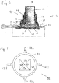
- the assembling apparatus 92 comprises at least one UV light source 82, preferably a plurality of UV light sources 82 (or UV sources for short) circumferentially arranged around the glue 80 and directed towards the glue, such that UV light emitted by the one or more UV sources 82 cures the glue 80.
- a plurality of UV light sources 82 or UV sources for short
- six UV sources may be used as indicated in Figure 3 (where two UV sources at the left side are not visible), or four UV sources 82 as in Figure 5 , while any other number of UV light sources 82 may be possible.
- Operation of the one or more UV sources 82 is controlled by the electronic control device 95.
- a signal from the image sensor 24 within the camera module 12, being sensitive to UV light for some extent is used as a feedback signal for controlling the operation of the one or more UV sources 82.
- the UV source 82 is kept on as long as the image sensor 24 measures the change (intensity reduction) of the UV radiation to be above a predefined threshold, but the UV source 82 is shut off if the image sensor 24 measures the change (intensity reduction) of the UV radiation to be below a predefined threshold.
- the completely mounted camera unit 20 as shown in Figure 2 can be applied to a mono imaging means as well as to a stereo imaging means without any further adjustment, in particular without roll angle adjustment since the roll angle ⁇ z is inherently adjusted in the camera module 12 as described above. Also the bore sight of each camera module 12 is inherently well-defined, such that no additional bore sight adjustment between two camera modules 12 is required for stereo systems. In this manner, a universally usable camera module 12 or camera eye is provided.
- the sensitive area of the imaging device is preferably divided into a number of areas 87a, 87b, 87c, 87d, where each of the areas 87a, 87b, 87c, 87d corresponds to a particular UV source 82a, 82b, 82c, 82d.
- the most proximate area e.g. 87a
- the UV illumination by each UV source 82a, 82b, 82c, 82d using a feedback signal from the corresponding area 87a, 87b, 87c, 87d on the imaging device 24.
- a more refined, or sectioned, control of the UV sources 82a, 82b, 82c, 82d and/or the UV curable adhesive 80 is achieved.
- n may be the number of UV light sources available (here 4).
- n separate weight maps may be used.
- each pixel has an associated weight.
- a weighted measurement is performed separately for each UV source 82a, 82b, 82c, 82d based on the corresponding weight map.
- overlapping areas are possible for the UV sources 82a, 82b, 82c, 82d.
- the lens holder 53 and the lens objective 20 are separate parts, together forming the lens unit 86.
- the lens unit 86 may be formed by the lens objective 20, i.e., the one or more lenses are directly integrated into the lens holder to form a uniform lens unit 86, such that a separate lens holder 53 is not necessary (so-called unibody embodiment).
- the lens objective 20 can be the identical to the lens unit 86, where the cylindrical casing of the lens objective 20 could form the lens holder.
- the glue joint 80 is provided between the lens objective 20 / the lens unit 86 and the back unit 90.
- the back plate 32 and the PCB 83 are separate parts, together forming the back unit 90.
- the back unit 90 may be formed by a rigid PCB 83, such that a separate back plate 32 is not necessary.
- the PCB 83 with mounted image sensor 24 can be the identical to the back unit 90.
Landscapes
- Physics & Mathematics (AREA)
- General Physics & Mathematics (AREA)
- Studio Devices (AREA)
Abstract
Description
- The invention relates to a method of assembling a camera module for a motor vehicle, comprising providing a lens unit forming a lens objective, providing a back unit carrying an image sensor, applying UV curable glue to the lens unit and/or to the back unit, positioning the lens unit and the back unit relative to each other, and curing the glue using at least one UV radiation source while holding the lens unit and the back unit in a relative position and orientation in order to form a glue joint between the lens unit and the back unit. The invention also relates to an apparatus for assembling a camera module for a motor vehicle.
- Such method and apparatus are known from
EP 2 942 937 A1 . -
DE 10 2010 047 106 A1 andWO 2011/131164 A1 respectively disclose a camera system where the lens objective is fixed relative to the image sensor by a glue joint between the lens objective and the lens holder. - UV curable glue is predominantly used in the alignment of lens objectives to image sensor parts in the volume production of fixed focus camera modules for automotive vision systems. UV exposure at constant level for a predetermined amount of time can result in changes of the intended curing result, causing larger spread and lower yield in key parameter performance. However, if a UV light sensor is used to monitor the UV exposure, it would obstruct some of the light which is intended for the curing process. Such a sensor would also measure the light only locally and not cover the complete area of interest. In the context of volume production for the automotive industry, there is a need to reduce the cycle time.
- The problem underlying the present invention is to provide a method of assembling a camera in volume production with low cycle time, constant curing results according to the specifications, and high yield in key parameter performance.
- The invention solves this objective with the features of the independent claims.
- According to the invention, during the glue curing, the at least one UV radiation source is controlled using feedback provided by the image sensor of the camera module. Because of the curing, the glue becomes less transparent. This can be measured by the image sensor of the camera module which, surprisingly, is sensitive to UV radiation to some extent. In this manner, the curing process can be controlled until the glue has reached a proper level of opaqueness, as determined by the feedback signal from the image sensor. Excessive UV illumination times can be avoided and the cycle time can be reduced.
- By utilizing the optical sensor in the camera module itself as a UV light intensity sensor, it is possible to monitor the UV intensity during the curing phase without blocking the optical path from the UV light sources. By assuring that the required UV cure strength is obtained, the cycle time can be optimized and the throughput can be increased.
- In embodiments of the invention, a weighted measurement of the complete sensitive area of the image sensor is performed. For example, a peripheral region of the image sensor, being arranged closer to the UV light sources, may be weighted higher in said evaluation than a central area of the image sensor.
- In the case of a plurality of UV light sources, the sensitive area of the image sensor is preferably evaluated in a plurality of areas, where each area corresponds to one or more of a plurality of UV light sources and/or to a particular section of the glue, as opposed to evaluating the sensitive area of the image sensor as a whole. In this embodiment, each UV light source can be individually controlled based on a feedback signal from the corresponding area of the image sensor, which allows a more refined, or sectioned, control of the UV sources and/or the UV adhesive.
- Preferably, a time-resolved measurement of UV radiation captured by the image sensor is performed. A time-resolved measurement during the UV exposure period allows to monitor the gradual curing of the glue as the UV intensity measured by the image sensor gradually reduces when the glue becomes less transparent due to the curing process.
- For a proper setup of the exposure equipment, the method is preferably used to measure light intensity from different UV sources, to balance the power and exposure from each UV source individually. This is preferably done by powering each UV source separately in sequence while capturing an image for each UV source exposure.
- Preferably, a dark image is captured with UV sources turned off, which can be used for background light subtraction to enhance the sensitivity of the measurement by the image sensor.
- The invention is particularly useful in an active alignment procedure comprising the steps of providing a lens unit, applying glue to the lens unit and/or to the back unit, positioning the lens unit and the back unit relative to each other, taking reference images, changing the position and/or orientation of the lens unit relative to the back unit until the relative position and/or orientation becomes optimal, and curing the glue while holding the lens unit and the back unit in the optimal relative position and orientation.
- During this active alignment, the yaw and pitch, or tip and tilt, of the lens objective is advantageously adjusted such that the image plane of the lens objective coincides with the image sensor. This implies that the lens objective is rotated around the two tip-tilt rotational degrees of freedom. The magnitude of these rotations is recorded by an alignment device. Furthermore, the x-y-position of the image in the sensitive plane of the image sensor is adjusted by moving the lens unit with the lens objective in x and y direction, such that the camera module will be looking straight once mounted into an external housing and the bore sight error is minimized. Due to the active alignment in the x and y directions the bore sight of each camera module is inherently well-defined, such that no additional bore sight adjustment between two camera modules is required for stereo systems.
- Furthermore, during the above active alignment the rotational or roll error of an object as seen by the image sensor is advantageously recorded by an alignment device. This recording is translated into a rotation of the lens unit itself, such that the image sensor is aligned to external features of the lens unit. These external features of the lens holder unit be used to mate the camera module into an external camera housing part.
- An aspect of the invention relates to an apparatus for assembling a camera module for a motor vehicle, comprising a manipulator adapted to hold a lens unit forming a lens objective and a back unit carrying an image sensor in a relative position and orientation, providing a glue dispenser adapted to apply UV curable glue to the lens unit and/or to the back unit, at least one UV radiation source adapted to illuminate the glue while the lens unit and the back unit are held in a relative position and orientation, in order to form a glue joint between the lens unit and the back unit. According to the invention, during said glue illumination, said at least one UV radiation source is controlled by an electronic control device using a feedback signal provided by the image sensor of the camera module.
- As described above, the invention is particularly useful for providing a feedback loop in production to secure curing stability. Other fields of use are possible, for example to optimize the glue bead amount and/or position by comparison of Δt; to compare different glue types UV-curing characteristics; to compare assembling apparatus setups by comparison of Δt.
- In the following the invention shall be illustrated on the basis of preferred embodiments with reference to the accompanying drawings, wherein:
- Fig. 1
- illustrates an assembling procedure of a camera unit using a lens unit;
- Fig. 2
- shows a cross-sectional view of an assembling apparatus for assembling a camera module;
- Fig. 3
- shows a top view of an assembling apparatus for assembling a camera module; and
- Fig. 4
- shows a perspective view of a back unit.
- In a preferred embodiment a camera module 12 (see
Figure 2 ) for a vision system of a motor vehicle comprises alens objective 20, alens holder 53 holding thelens objective 20, animage sensor 24 and aback plate 32 holding theimage sensor 24. Thelens objective 20 is pre-mounted to thelens holder 53 to form alens unit 86. Theimage sensor 24 and the printedcircuit board 83 are mounted to theback plate 32 to form aback unit 90. - The
lens unit 86, here thelens holder 53, is connected to theback unit 90, here theback plate 32, by means of aglue joint 80 which may be overall ring-shaped, or for example be composed of a plurality of glue dots. Theglue 80 is a UV curable glue. Thelens holder 53, theback plate 32 and theglue joint 80 form ahousing 22 which, together with thelens objective 20, is basically closed in a light tight manner except for an incident light opening 28. With respect to thermal stability, thelens holder 53 is preferably made of metal, for example Zinc alloy. Thelens objective 20 comprises one or more optical lenses held inside thelens objective 20. - The
lens holder 53 comprises atubular part 54 which is preferably cylindrical and extends parallel to the optical axis of thelens objective 20, and abase part 55 to connect thelens holder 53 to theback plate 32 by theglue joint 80. Thetubular part 54 of thelens holder 53 and thelens objective 20 are arranged concentrically to the optical axis of thelens objective 20. Thelens holder 53 preferably comprisesexternal features 94 or position defining means (seeFigure 3 ), which may be provided on the upper side of thebase part 55 of thelens holder 53, through which thecamera module 12 can be fastened with fixed orientation to an external part not shown in the Figures. - The
lens objective 20 is coaxially held in thetubular part 54 of thelens holder 53. Thelens objective 20 may be screwed into thelens holder 53. The connection between thelens objective 20 and thelens holder 54 may be fixed byglue 81. - Incident light falls through the
opening 28 and is focussed by thelens objective 20 in the image plane A of thelens objective 20. The sensitive plane of theimage sensor 24 is advantageously disposed at or in the image plane of thelens objective 20. Theimage sensor 24 is preferably a two-dimensional image sensor, in particular an optical sensor having maximum sensitivity in the visible wavelength region, and is adapted to convert incident light into an electrical signal containing image information. Theimage sensor 24 may for example be a CCD sensor or a CMOS sensor. - The
rigid back plate 32 is preferably made of metal, in particular steel. The printedcircuit board 83 is preferably a flexible printed circuit board arranged on the sensor side of theback plate 32. The printedcircuit board 83 has aninner opening 84 to be placed around theimage sensor 24 as may be seen inFigure 4 . Furthermore, the printedcircuit board 83 is preferably smaller than theback plate 32 to leave one or moreblank areas 85, for example margins, of theback plate 32 where it is not covered by thePCB 83, such that thelens holder 53 can be directly attached to theback plate 32 in the region of theblank areas 85 by theglue joint 80. In the embodiment shown inFigure 3 , theblank areas 85 are formed by margins along three edges of theback plate 32, such that an overall U-shapedblank area 85 is formed. Theblank areas 85 may also be formed by through-holes in thePCB 83, for example. - The assembling procedure of the
camera module 12 is explained in the following with reference toFigures 1 and2 . - The mounted back
unit 90 is placed for example on a holder 91 of an assemblingapparatus 92. In particular, the assemblingapparatus 92 may comprise a carrousel and the holder 91 may be rotatable. In a first rotation position of the holder 91, thelens unit 86 and theback unit 90 are loaded into the assemblingapparatus 92. Also indexing may be performed here. Next, for example in a second rotation position of the holder 91, UV-curable glue 80 is dispended onto theblank area 85 on the sensor side of thebase plate 32, or alternatively to the bottom side of thelens holder 53, by a glue dispenser not shown in the Figures. - An active alignment procedure of the relative position of the
lens unit 86 and theback unit 90 is then performed, for example in a third rotational position of the holder 91. Amanipulator 93, which may for example engage in the position defining elements 94 (seeFigure 3 ), is controllable by aelectronic control device 95, which is only schematically shown inFigure 1 , to adjust the position of thelens holder 53 orlens unit 86 relative to the position of theback plate 32 or backunit 90 along six degrees of freedom, namely in x-y-direction perpendicular to the optical z-axis for bore sight correction, tip-tilt angle Θx, Θy adjustment, focus adjustment along the optical z-axis, and, with respect to stereo applications of thecamera module 12, roll angle Θz adjustment. - In the active alignment procedure, reference images of a reference object not shown in
Figure 1 are continuously taken by theimage sensor 24 while moving thelens unit 86 relative to theback unit 90 along the optical z-axis and/or changing the tip and tilt angles Θx, Θy. In every relative position of thelens unit 86 and theback unit 90, the image quality is evaluated by theelectronic control device 95 and the evaluated image quality is used as feedback for controlling themanipulator 93 in order to adjust thelens objective 20. - The x-y position of the
lens unit 86 relative to theback unit 90 is adjusted such that the bore sight error is minimal. Due to this adjustment, a generally non-zero offset between the optical z-axis and the geometrical centre of theimage sensor 24 is provided, such that the optical z-axis is generally not centered on the sensitive surface of theimage sensor 24. - The roll angle Θz is adjusted such that an image taken by the
image sensor 24 has a pre-determined roll alignment relative to thelens holder 53. For example, the lines and rows of the images could be aligned to be parallel to the edges of thelens holder 53, without limitation to this particular alignment. - The procedure described so far is an active alignment procedure as described in
EP 2 942 937 A1 , allowing five or six degrees of freedom for the alignment to be optimized. - When the image quality determined by the
image sensor 24 has become optimal and the x-y position and the roll angle Θz have been properly adjusted, theglue 80 is cured by applying UV radiation while holding thelens unit 86 and theback unit 90 in the optimal relative position. This is explained in the following with reference toFigure 2 . - The assembling
apparatus 92 comprises at least oneUV light source 82, preferably a plurality of UV light sources 82 (or UV sources for short) circumferentially arranged around theglue 80 and directed towards the glue, such that UV light emitted by the one ormore UV sources 82 cures theglue 80. As an example, six UV sources may be used as indicated inFigure 3 (where two UV sources at the left side are not visible), or fourUV sources 82 as inFigure 5 , while any other number of UVlight sources 82 may be possible. - Operation of the one or
more UV sources 82 is controlled by theelectronic control device 95. According to the invention, a signal from theimage sensor 24 within thecamera module 12, being sensitive to UV light for some extent, is used as a feedback signal for controlling the operation of the one or more UV sources 82. For example, theUV source 82 is kept on as long as theimage sensor 24 measures the change (intensity reduction) of the UV radiation to be above a predefined threshold, but theUV source 82 is shut off if theimage sensor 24 measures the change (intensity reduction) of the UV radiation to be below a predefined threshold. - A practical flowchart for a glue curing process could be as follows:
- a) Record intensity I on the
image sensor 24 at the start of the UV illumination by the UV source(s) 82; subtract background level (dark image). - b) Continue illuminating
glue 80 by UV source(s) 82 for a time period Δt. - c) Record intensity I' on the
image sensor 24 by the UV source(s) 82; subtract background level (dark image). - d) If I'/I is below a predefined threshold, shut off UV illumination by UV source(s) 82; otherwise, go to step b).
- Another practical flowchart for a glue curing process could be as follows:
- a) Record intensity I on the
image sensor 24 at the start of the UV illumination by the UV source(s) 82. - b) Continue illuminating
glue 80 by UV source(s) 82 for a time period Δt. - c) Record intensity I' on the
image sensor 24 by the UV source(s) 82. - d) If I-I' is above a predefined threshold, shut off UV illumination by UV source(s) 82; otherwise, go to step b).
- When the
glue 80 is cured, the completely mountedcamera unit 20 as shown inFigure 2 can be applied to a mono imaging means as well as to a stereo imaging means without any further adjustment, in particular without roll angle adjustment since the roll angle Θz is inherently adjusted in thecamera module 12 as described above. Also the bore sight of eachcamera module 12 is inherently well-defined, such that no additional bore sight adjustment between twocamera modules 12 is required for stereo systems. In this manner, a universallyusable camera module 12 or camera eye is provided. - A preferred embodiment employing a plurality of
UV sources 82, here for example fourUV sources Figure 5 . In such embodiment, the sensitive area of the imaging device is preferably divided into a number ofareas areas particular UV source UV source area imaging device 24. In this manner, a more refined, or sectioned, control of theUV sources curable adhesive 80 is achieved. - In Figure the
image sensor 24 is split into n discrete parts, where n may be the number of UV light sources available (here 4). In another embodiment, n separate weight maps may be used. In a weight map, each pixel has an associated weight. In this embodiment, a weighted measurement is performed separately for eachUV source UV sources - In the embodiment shown in the figures, the
lens holder 53 and thelens objective 20 are separate parts, together forming thelens unit 86. Other embodiments of thelens unit 86 are possible. In particular, thelens unit 86 may be formed by thelens objective 20, i.e., the one or more lenses are directly integrated into the lens holder to form auniform lens unit 86, such that aseparate lens holder 53 is not necessary (so-called unibody embodiment). In other words, thelens objective 20 can be the identical to thelens unit 86, where the cylindrical casing of thelens objective 20 could form the lens holder. In the unibody embodiment, the glue joint 80 is provided between thelens objective 20 / thelens unit 86 and theback unit 90. - Similarly, in the embodiment shown in the figures, the
back plate 32 and thePCB 83 are separate parts, together forming theback unit 90. Other embodiments of theback unit 90 are possible. In particular, theback unit 90 may be formed by arigid PCB 83, such that aseparate back plate 32 is not necessary. In other words, thePCB 83 with mountedimage sensor 24 can be the identical to theback unit 90.
Claims (8)
- A method of assembling a camera module (12) for a motor vehicle, comprising providing a lens unit (86) forming a lens objective (20), providing a back unit (90) carrying an image sensor (24), applying UV curable glue (80) to the lens unit (86) and/or to the back unit (90), positioning the lens unit (86) and the back unit (90) relative to each other, and curing the glue (80) using at least one UV radiation source (82) while holding the lens unit (86) and the back unit (90) in a relative position and orientation in order to form a glue joint (80) between the lens unit (86) and the back unit (90), characterized in that during said glue curing, said at least one UV radiation source (82) is controlled using a feedback signal provided by the image sensor (24) of the camera module (12).
- The method as claimed in claim 1, characterized in that the UV source (82) is kept on as long as the image sensor (24) measures that the change of the UV radiation is above a predefined threshold, whereas the UV source (82) is shut off when the image sensor (24) measures that the change of the UV radiation is below a predefined threshold.
- The method as claimed in any one of the preceding claims, characterized in that a weighted measurement of the complete sensitive area of the image sensor (24) is performed.
- The method as claimed in any one of the preceding claims, characterized in that the sensitive area of the image sensor (24) is evaluated in a plurality of areas (87a-87d), where each area (87a-87d) corresponds to one or more of a plurality of UV light sources (82a-82d) and/or to a particular section of the glue (80), wherein each UV light source (82a-82d) is individually controlled based on a feedback signal from the corresponding area (87a-87d) of the image sensor (24).
- The method as claimed in any one of the preceding claims, characterized in that a time-resolved measurement of UV radiation captured by the image sensor (24) is performed.
- The method as claimed in any one of the preceding claims, characterized by the following procedure:a) record intensity I on the image sensor (24) at the start of the UV illumination by the UV source (82), subtract background level or dark image;b) continue illuminating glue (80) by UV source (82) for a time period Δt;c) record intensity I' on the image sensor (24) by the UV source (82), subtract background level or dark image;d) if I'/I is below a predefined threshold, shut off UV illumination by UV source (82), otherwise, go to step b).
- The method as claimed in any one of claims 1 to 5, characterized by the following procedure:a) record intensity I on the image sensor (24) at the start of the UV illumination by the UV source (82);b) continue illuminating glue (80) by UV source (82) for a time period Δt;c) record intensity I' on the image sensor (24) by the UV source (82);d) if I-I' is above a predefined threshold, shut off UV illumination by UV source (82), otherwise, go to step b).
- An apparatus (92) for assembling a camera module (12) for a motor vehicle, comprising a manipulator (93) adapted to hold a lens unit (86) forming a lens objective (20), and a back unit (90) carrying an image sensor (24) in a relative position and orientation providing, a glue dispenser adapted to apply UV curable glue (80) to the lens unit (86) and/or to the back unit (90), at least one UV radiation source (82) adapted to illuminate the glue (80) while the lens unit (86) and the back unit (90) are held in a relative position and orientation, in order to form a glue joint (80) between the lens unit (86) and the back unit (90), characterized in that during said glue illumination, said at least one UV radiation source (82) is controlled by an electronic control device (95) using a feedback signal provided by the image sensor (24) of the camera module (12).
Priority Applications (1)
| Application Number | Priority Date | Filing Date | Title |
|---|---|---|---|
| EP19192829.0A EP3783429B1 (en) | 2019-08-21 | 2019-08-21 | Method and apparatus for assembling a camera module for a motor vehicle |
Applications Claiming Priority (1)
| Application Number | Priority Date | Filing Date | Title |
|---|---|---|---|
| EP19192829.0A EP3783429B1 (en) | 2019-08-21 | 2019-08-21 | Method and apparatus for assembling a camera module for a motor vehicle |
Publications (2)
| Publication Number | Publication Date |
|---|---|
| EP3783429A1 true EP3783429A1 (en) | 2021-02-24 |
| EP3783429B1 EP3783429B1 (en) | 2022-06-22 |
Family
ID=67659680
Family Applications (1)
| Application Number | Title | Priority Date | Filing Date |
|---|---|---|---|
| EP19192829.0A Active EP3783429B1 (en) | 2019-08-21 | 2019-08-21 | Method and apparatus for assembling a camera module for a motor vehicle |
Country Status (1)
| Country | Link |
|---|---|
| EP (1) | EP3783429B1 (en) |
Cited By (1)
| Publication number | Priority date | Publication date | Assignee | Title |
|---|---|---|---|---|
| CN115608562A (en) * | 2022-09-28 | 2023-01-17 | 天地伟业技术有限公司 | A production device for black light lens AA focusing and its control method |
Citations (7)
| Publication number | Priority date | Publication date | Assignee | Title |
|---|---|---|---|---|
| US20070159703A1 (en) * | 2005-12-12 | 2007-07-12 | Uwe Apel | Optical module and method for assembling an optical module |
| WO2011131164A1 (en) | 2010-04-21 | 2011-10-27 | Conti Temic Microelectronic Gmbh | Optical device and method for positioning an optical element above an image recording element |
| DE102010047106A1 (en) | 2010-10-01 | 2012-04-05 | Conti Temic Microelectronic Gmbh | Device, particularly optical device, has objective and carrier housing, where objective is mounted in carrier housing, and objective and carrier housing are connected with each other through adhesive connection |
| EP2942937A1 (en) | 2014-05-07 | 2015-11-11 | Autoliv Development AB | Camera module for a motor vehicle and method of mounting a camera module |
| EP3121886A1 (en) * | 2014-03-18 | 2017-01-25 | Toyota Jidosha Kabushiki Kaisha | Fuel cell, fuel cell manufacturing device |
| EP3438721A1 (en) * | 2009-03-25 | 2019-02-06 | Magna Electronics Inc. | Vehicular camera and lens assembly |
| CN109491179A (en) * | 2018-11-29 | 2019-03-19 | 业成科技(成都)有限公司 | Lens barrel structure and its assemble method |
-
2019
- 2019-08-21 EP EP19192829.0A patent/EP3783429B1/en active Active
Patent Citations (7)
| Publication number | Priority date | Publication date | Assignee | Title |
|---|---|---|---|---|
| US20070159703A1 (en) * | 2005-12-12 | 2007-07-12 | Uwe Apel | Optical module and method for assembling an optical module |
| EP3438721A1 (en) * | 2009-03-25 | 2019-02-06 | Magna Electronics Inc. | Vehicular camera and lens assembly |
| WO2011131164A1 (en) | 2010-04-21 | 2011-10-27 | Conti Temic Microelectronic Gmbh | Optical device and method for positioning an optical element above an image recording element |
| DE102010047106A1 (en) | 2010-10-01 | 2012-04-05 | Conti Temic Microelectronic Gmbh | Device, particularly optical device, has objective and carrier housing, where objective is mounted in carrier housing, and objective and carrier housing are connected with each other through adhesive connection |
| EP3121886A1 (en) * | 2014-03-18 | 2017-01-25 | Toyota Jidosha Kabushiki Kaisha | Fuel cell, fuel cell manufacturing device |
| EP2942937A1 (en) | 2014-05-07 | 2015-11-11 | Autoliv Development AB | Camera module for a motor vehicle and method of mounting a camera module |
| CN109491179A (en) * | 2018-11-29 | 2019-03-19 | 业成科技(成都)有限公司 | Lens barrel structure and its assemble method |
Cited By (1)
| Publication number | Priority date | Publication date | Assignee | Title |
|---|---|---|---|---|
| CN115608562A (en) * | 2022-09-28 | 2023-01-17 | 天地伟业技术有限公司 | A production device for black light lens AA focusing and its control method |
Also Published As
| Publication number | Publication date |
|---|---|
| EP3783429B1 (en) | 2022-06-22 |
Similar Documents
| Publication | Publication Date | Title |
|---|---|---|
| EP2942937B1 (en) | Camera module for a motor vehicle and method of mounting a camera module | |
| EP3438721B1 (en) | Vehicular camera and lens assembly | |
| US7532247B2 (en) | Image pickup apparatus | |
| CN114439827B (en) | Camera module assembly equipment and assembly method | |
| US9927594B2 (en) | Image pickup module manufacturing method and image pickup module manufacturing device | |
| US20060042064A1 (en) | Method for assembling a camera module | |
| CN110632727B (en) | Optical lens, camera module and assembling method thereof | |
| JP2011133509A (en) | Method for assembling camera module | |
| JP2005274925A (en) | Focusing method and focusing device | |
| US20060263076A1 (en) | Image projection apparatus, projection image pattern, laser drive apparatus, camera apparatus | |
| JP2023501758A (en) | Systems and methods for optical alignment and calibration of infrared camera lenses | |
| JP3766835B2 (en) | Lens system adjusting device and lens system adjusting method using the same | |
| WO2005010461A1 (en) | Position detection device, position detection method, test device, and camera module manufacturing device | |
| EP3783429B1 (en) | Method and apparatus for assembling a camera module for a motor vehicle | |
| US9906695B2 (en) | Manufacturing method of imaging module and imaging module manufacturing apparatus | |
| US7375360B2 (en) | Light device of arranging thin film inspection sensor array, and method and apparatus for arranging sensor array using the same | |
| KR102830714B1 (en) | Devices, methods and uses of such devices for controlling, assembling and/or testing electro-optical systems | |
| JP2010054677A (en) | Method and device for adjusting tilt of lens | |
| US9366839B2 (en) | Position adjustment device and position adjustment method | |
| JP2006030256A (en) | Focus adjustment method and focus adjustment apparatus for imaging apparatus | |
| KR102500032B1 (en) | Lens assembly and camera module including the lens assembly | |
| JP2004163949A (en) | Microscope, and method for changing light flux in microscope | |
| JP4799324B2 (en) | Exposure apparatus, exposure method, and manufacturing method of display panel substrate | |
| EP4080868B1 (en) | Work machine | |
| JP2006165883A (en) | Focus adjusting device and focus adjusting method |
Legal Events
| Date | Code | Title | Description |
|---|---|---|---|
| PUAI | Public reference made under article 153(3) epc to a published international application that has entered the european phase |
Free format text: ORIGINAL CODE: 0009012 |
|
| STAA | Information on the status of an ep patent application or granted ep patent |
Free format text: STATUS: THE APPLICATION HAS BEEN PUBLISHED |
|
| AK | Designated contracting states |
Kind code of ref document: A1 Designated state(s): AL AT BE BG CH CY CZ DE DK EE ES FI FR GB GR HR HU IE IS IT LI LT LU LV MC MK MT NL NO PL PT RO RS SE SI SK SM TR |
|
| AX | Request for extension of the european patent |
Extension state: BA ME |
|
| STAA | Information on the status of an ep patent application or granted ep patent |
Free format text: STATUS: REQUEST FOR EXAMINATION WAS MADE |
|
| 17P | Request for examination filed |
Effective date: 20210812 |
|
| RBV | Designated contracting states (corrected) |
Designated state(s): AL AT BE BG CH CY CZ DE DK EE ES FI FR GB GR HR HU IE IS IT LI LT LU LV MC MK MT NL NO PL PT RO RS SE SI SK SM TR |
|
| REG | Reference to a national code |
Ref country code: DE Ref legal event code: R079 Ref document number: 602019016091 Country of ref document: DE Free format text: PREVIOUS MAIN CLASS: G03B0017020000 Ipc: G03B0030000000 |
|
| RIC1 | Information provided on ipc code assigned before grant |
Ipc: G03B 30/00 20210101AFI20220113BHEP |
|
| GRAP | Despatch of communication of intention to grant a patent |
Free format text: ORIGINAL CODE: EPIDOSNIGR1 |
|
| STAA | Information on the status of an ep patent application or granted ep patent |
Free format text: STATUS: GRANT OF PATENT IS INTENDED |
|
| INTG | Intention to grant announced |
Effective date: 20220302 |
|
| GRAS | Grant fee paid |
Free format text: ORIGINAL CODE: EPIDOSNIGR3 |
|
| GRAA | (expected) grant |
Free format text: ORIGINAL CODE: 0009210 |
|
| STAA | Information on the status of an ep patent application or granted ep patent |
Free format text: STATUS: THE PATENT HAS BEEN GRANTED |
|
| AK | Designated contracting states |
Kind code of ref document: B1 Designated state(s): AL AT BE BG CH CY CZ DE DK EE ES FI FR GB GR HR HU IE IS IT LI LT LU LV MC MK MT NL NO PL PT RO RS SE SI SK SM TR |
|
| REG | Reference to a national code |
Ref country code: GB Ref legal event code: FG4D |
|
| REG | Reference to a national code |
Ref country code: CH Ref legal event code: EP |
|
| REG | Reference to a national code |
Ref country code: DE Ref legal event code: R096 Ref document number: 602019016091 Country of ref document: DE |
|
| REG | Reference to a national code |
Ref country code: AT Ref legal event code: REF Ref document number: 1500148 Country of ref document: AT Kind code of ref document: T Effective date: 20220715 |
|
| REG | Reference to a national code |
Ref country code: IE Ref legal event code: FG4D |
|
| RAP2 | Party data changed (patent owner data changed or rights of a patent transferred) |
Owner name: ARRIVER SOFTWARE AB |
|
| REG | Reference to a national code |
Ref country code: DE Ref legal event code: R081 Ref document number: 602019016091 Country of ref document: DE Owner name: ARRIVER SOFTWARE AB, SE Free format text: FORMER OWNER: VEONEER SWEDEN AB, VARGARDA, SE Ref country code: DE Ref legal event code: R081 Ref document number: 602019016091 Country of ref document: DE Owner name: QUALCOMM AUTO LTD., CAMBRIDGE, GB Free format text: FORMER OWNER: VEONEER SWEDEN AB, VARGARDA, SE |
|
| REG | Reference to a national code |
Ref country code: LT Ref legal event code: MG9D |
|
| REG | Reference to a national code |
Ref country code: NL Ref legal event code: MP Effective date: 20220622 |
|
| PG25 | Lapsed in a contracting state [announced via postgrant information from national office to epo] |
Ref country code: SE Free format text: LAPSE BECAUSE OF FAILURE TO SUBMIT A TRANSLATION OF THE DESCRIPTION OR TO PAY THE FEE WITHIN THE PRESCRIBED TIME-LIMIT Effective date: 20220622 Ref country code: NO Free format text: LAPSE BECAUSE OF FAILURE TO SUBMIT A TRANSLATION OF THE DESCRIPTION OR TO PAY THE FEE WITHIN THE PRESCRIBED TIME-LIMIT Effective date: 20220922 Ref country code: LT Free format text: LAPSE BECAUSE OF FAILURE TO SUBMIT A TRANSLATION OF THE DESCRIPTION OR TO PAY THE FEE WITHIN THE PRESCRIBED TIME-LIMIT Effective date: 20220622 Ref country code: HR Free format text: LAPSE BECAUSE OF FAILURE TO SUBMIT A TRANSLATION OF THE DESCRIPTION OR TO PAY THE FEE WITHIN THE PRESCRIBED TIME-LIMIT Effective date: 20220622 Ref country code: GR Free format text: LAPSE BECAUSE OF FAILURE TO SUBMIT A TRANSLATION OF THE DESCRIPTION OR TO PAY THE FEE WITHIN THE PRESCRIBED TIME-LIMIT Effective date: 20220923 Ref country code: FI Free format text: LAPSE BECAUSE OF FAILURE TO SUBMIT A TRANSLATION OF THE DESCRIPTION OR TO PAY THE FEE WITHIN THE PRESCRIBED TIME-LIMIT Effective date: 20220622 Ref country code: BG Free format text: LAPSE BECAUSE OF FAILURE TO SUBMIT A TRANSLATION OF THE DESCRIPTION OR TO PAY THE FEE WITHIN THE PRESCRIBED TIME-LIMIT Effective date: 20220922 |
|
| REG | Reference to a national code |
Ref country code: GB Ref legal event code: 732E Free format text: REGISTERED BETWEEN 20221006 AND 20221012 |
|
| REG | Reference to a national code |
Ref country code: AT Ref legal event code: MK05 Ref document number: 1500148 Country of ref document: AT Kind code of ref document: T Effective date: 20220622 |
|
| PG25 | Lapsed in a contracting state [announced via postgrant information from national office to epo] |
Ref country code: RS Free format text: LAPSE BECAUSE OF FAILURE TO SUBMIT A TRANSLATION OF THE DESCRIPTION OR TO PAY THE FEE WITHIN THE PRESCRIBED TIME-LIMIT Effective date: 20220622 Ref country code: LV Free format text: LAPSE BECAUSE OF FAILURE TO SUBMIT A TRANSLATION OF THE DESCRIPTION OR TO PAY THE FEE WITHIN THE PRESCRIBED TIME-LIMIT Effective date: 20220622 |
|
| PG25 | Lapsed in a contracting state [announced via postgrant information from national office to epo] |
Ref country code: NL Free format text: LAPSE BECAUSE OF FAILURE TO SUBMIT A TRANSLATION OF THE DESCRIPTION OR TO PAY THE FEE WITHIN THE PRESCRIBED TIME-LIMIT Effective date: 20220622 |
|
| PG25 | Lapsed in a contracting state [announced via postgrant information from national office to epo] |
Ref country code: SM Free format text: LAPSE BECAUSE OF FAILURE TO SUBMIT A TRANSLATION OF THE DESCRIPTION OR TO PAY THE FEE WITHIN THE PRESCRIBED TIME-LIMIT Effective date: 20220622 Ref country code: SK Free format text: LAPSE BECAUSE OF FAILURE TO SUBMIT A TRANSLATION OF THE DESCRIPTION OR TO PAY THE FEE WITHIN THE PRESCRIBED TIME-LIMIT Effective date: 20220622 Ref country code: RO Free format text: LAPSE BECAUSE OF FAILURE TO SUBMIT A TRANSLATION OF THE DESCRIPTION OR TO PAY THE FEE WITHIN THE PRESCRIBED TIME-LIMIT Effective date: 20220622 Ref country code: PT Free format text: LAPSE BECAUSE OF FAILURE TO SUBMIT A TRANSLATION OF THE DESCRIPTION OR TO PAY THE FEE WITHIN THE PRESCRIBED TIME-LIMIT Effective date: 20221024 Ref country code: ES Free format text: LAPSE BECAUSE OF FAILURE TO SUBMIT A TRANSLATION OF THE DESCRIPTION OR TO PAY THE FEE WITHIN THE PRESCRIBED TIME-LIMIT Effective date: 20220622 Ref country code: EE Free format text: LAPSE BECAUSE OF FAILURE TO SUBMIT A TRANSLATION OF THE DESCRIPTION OR TO PAY THE FEE WITHIN THE PRESCRIBED TIME-LIMIT Effective date: 20220622 Ref country code: CZ Free format text: LAPSE BECAUSE OF FAILURE TO SUBMIT A TRANSLATION OF THE DESCRIPTION OR TO PAY THE FEE WITHIN THE PRESCRIBED TIME-LIMIT Effective date: 20220622 Ref country code: AT Free format text: LAPSE BECAUSE OF FAILURE TO SUBMIT A TRANSLATION OF THE DESCRIPTION OR TO PAY THE FEE WITHIN THE PRESCRIBED TIME-LIMIT Effective date: 20220622 |
|
| PG25 | Lapsed in a contracting state [announced via postgrant information from national office to epo] |
Ref country code: PL Free format text: LAPSE BECAUSE OF FAILURE TO SUBMIT A TRANSLATION OF THE DESCRIPTION OR TO PAY THE FEE WITHIN THE PRESCRIBED TIME-LIMIT Effective date: 20220622 Ref country code: IS Free format text: LAPSE BECAUSE OF FAILURE TO SUBMIT A TRANSLATION OF THE DESCRIPTION OR TO PAY THE FEE WITHIN THE PRESCRIBED TIME-LIMIT Effective date: 20221022 |
|
| REG | Reference to a national code |
Ref country code: DE Ref legal event code: R097 Ref document number: 602019016091 Country of ref document: DE |
|
| PG25 | Lapsed in a contracting state [announced via postgrant information from national office to epo] |
Ref country code: MC Free format text: LAPSE BECAUSE OF FAILURE TO SUBMIT A TRANSLATION OF THE DESCRIPTION OR TO PAY THE FEE WITHIN THE PRESCRIBED TIME-LIMIT Effective date: 20220622 Ref country code: AL Free format text: LAPSE BECAUSE OF FAILURE TO SUBMIT A TRANSLATION OF THE DESCRIPTION OR TO PAY THE FEE WITHIN THE PRESCRIBED TIME-LIMIT Effective date: 20220622 |
|
| REG | Reference to a national code |
Ref country code: CH Ref legal event code: PL |
|
| PG25 | Lapsed in a contracting state [announced via postgrant information from national office to epo] |
Ref country code: LU Free format text: LAPSE BECAUSE OF NON-PAYMENT OF DUE FEES Effective date: 20220821 Ref country code: LI Free format text: LAPSE BECAUSE OF NON-PAYMENT OF DUE FEES Effective date: 20220831 Ref country code: DK Free format text: LAPSE BECAUSE OF FAILURE TO SUBMIT A TRANSLATION OF THE DESCRIPTION OR TO PAY THE FEE WITHIN THE PRESCRIBED TIME-LIMIT Effective date: 20220622 Ref country code: CH Free format text: LAPSE BECAUSE OF NON-PAYMENT OF DUE FEES Effective date: 20220831 |
|
| PLBE | No opposition filed within time limit |
Free format text: ORIGINAL CODE: 0009261 |
|
| STAA | Information on the status of an ep patent application or granted ep patent |
Free format text: STATUS: NO OPPOSITION FILED WITHIN TIME LIMIT |
|
| REG | Reference to a national code |
Ref country code: BE Ref legal event code: MM Effective date: 20220831 |
|
| 26N | No opposition filed |
Effective date: 20230323 |
|
| PG25 | Lapsed in a contracting state [announced via postgrant information from national office to epo] |
Ref country code: IE Free format text: LAPSE BECAUSE OF NON-PAYMENT OF DUE FEES Effective date: 20220821 |
|
| PG25 | Lapsed in a contracting state [announced via postgrant information from national office to epo] |
Ref country code: SI Free format text: LAPSE BECAUSE OF FAILURE TO SUBMIT A TRANSLATION OF THE DESCRIPTION OR TO PAY THE FEE WITHIN THE PRESCRIBED TIME-LIMIT Effective date: 20220622 |
|
| PG25 | Lapsed in a contracting state [announced via postgrant information from national office to epo] |
Ref country code: BE Free format text: LAPSE BECAUSE OF NON-PAYMENT OF DUE FEES Effective date: 20220831 |
|
| PG25 | Lapsed in a contracting state [announced via postgrant information from national office to epo] |
Ref country code: IT Free format text: LAPSE BECAUSE OF FAILURE TO SUBMIT A TRANSLATION OF THE DESCRIPTION OR TO PAY THE FEE WITHIN THE PRESCRIBED TIME-LIMIT Effective date: 20220622 |
|
| PG25 | Lapsed in a contracting state [announced via postgrant information from national office to epo] |
Ref country code: CY Free format text: LAPSE BECAUSE OF FAILURE TO SUBMIT A TRANSLATION OF THE DESCRIPTION OR TO PAY THE FEE WITHIN THE PRESCRIBED TIME-LIMIT Effective date: 20220622 |
|
| PG25 | Lapsed in a contracting state [announced via postgrant information from national office to epo] |
Ref country code: MK Free format text: LAPSE BECAUSE OF FAILURE TO SUBMIT A TRANSLATION OF THE DESCRIPTION OR TO PAY THE FEE WITHIN THE PRESCRIBED TIME-LIMIT Effective date: 20220622 Ref country code: HU Free format text: LAPSE BECAUSE OF FAILURE TO SUBMIT A TRANSLATION OF THE DESCRIPTION OR TO PAY THE FEE WITHIN THE PRESCRIBED TIME-LIMIT; INVALID AB INITIO Effective date: 20190821 |
|
| PG25 | Lapsed in a contracting state [announced via postgrant information from national office to epo] |
Ref country code: MT Free format text: LAPSE BECAUSE OF FAILURE TO SUBMIT A TRANSLATION OF THE DESCRIPTION OR TO PAY THE FEE WITHIN THE PRESCRIBED TIME-LIMIT Effective date: 20220622 |
|
| REG | Reference to a national code |
Ref country code: DE Ref legal event code: R081 Ref document number: 602019016091 Country of ref document: DE Owner name: QUALCOMM AUTO LTD., CAMBRIDGE, GB Free format text: FORMER OWNER: ARRIVER SOFTWARE AB, LINKOEPING, SE |
|
| PG25 | Lapsed in a contracting state [announced via postgrant information from national office to epo] |
Ref country code: BG Free format text: LAPSE BECAUSE OF FAILURE TO SUBMIT A TRANSLATION OF THE DESCRIPTION OR TO PAY THE FEE WITHIN THE PRESCRIBED TIME-LIMIT Effective date: 20220622 |
|
| REG | Reference to a national code |
Ref country code: GB Ref legal event code: 732E Free format text: REGISTERED BETWEEN 20241024 AND 20241030 |
|
| PG25 | Lapsed in a contracting state [announced via postgrant information from national office to epo] |
Ref country code: BG Free format text: LAPSE BECAUSE OF FAILURE TO SUBMIT A TRANSLATION OF THE DESCRIPTION OR TO PAY THE FEE WITHIN THE PRESCRIBED TIME-LIMIT Effective date: 20220622 |
|
| PGFP | Annual fee paid to national office [announced via postgrant information from national office to epo] |
Ref country code: DE Payment date: 20250709 Year of fee payment: 7 |
|
| PGFP | Annual fee paid to national office [announced via postgrant information from national office to epo] |
Ref country code: GB Payment date: 20250710 Year of fee payment: 7 |
|
| PGFP | Annual fee paid to national office [announced via postgrant information from national office to epo] |
Ref country code: FR Payment date: 20250709 Year of fee payment: 7 |
|
| PG25 | Lapsed in a contracting state [announced via postgrant information from national office to epo] |
Ref country code: TR Free format text: LAPSE BECAUSE OF FAILURE TO SUBMIT A TRANSLATION OF THE DESCRIPTION OR TO PAY THE FEE WITHIN THE PRESCRIBED TIME-LIMIT Effective date: 20220622 |