EP3783382A1 - Electronic device, method for controlling electronic device, and program for controlling electronic device - Google Patents
Electronic device, method for controlling electronic device, and program for controlling electronic device Download PDFInfo
- Publication number
- EP3783382A1 EP3783382A1 EP19787755.8A EP19787755A EP3783382A1 EP 3783382 A1 EP3783382 A1 EP 3783382A1 EP 19787755 A EP19787755 A EP 19787755A EP 3783382 A1 EP3783382 A1 EP 3783382A1
- Authority
- EP
- European Patent Office
- Prior art keywords
- band
- electronic device
- sensor
- vehicle
- transmission wave
- Prior art date
- Legal status (The legal status is an assumption and is not a legal conclusion. Google has not performed a legal analysis and makes no representation as to the accuracy of the status listed.)
- Granted
Links
Images





Classifications
-
- G—PHYSICS
- G01—MEASURING; TESTING
- G01S—RADIO DIRECTION-FINDING; RADIO NAVIGATION; DETERMINING DISTANCE OR VELOCITY BY USE OF RADIO WAVES; LOCATING OR PRESENCE-DETECTING BY USE OF THE REFLECTION OR RERADIATION OF RADIO WAVES; ANALOGOUS ARRANGEMENTS USING OTHER WAVES
- G01S13/00—Systems using the reflection or reradiation of radio waves, e.g. radar systems; Analogous systems using reflection or reradiation of waves whose nature or wavelength is irrelevant or unspecified
- G01S13/88—Radar or analogous systems specially adapted for specific applications
- G01S13/93—Radar or analogous systems specially adapted for specific applications for anti-collision purposes
- G01S13/931—Radar or analogous systems specially adapted for specific applications for anti-collision purposes of land vehicles
-
- G—PHYSICS
- G01—MEASURING; TESTING
- G01S—RADIO DIRECTION-FINDING; RADIO NAVIGATION; DETERMINING DISTANCE OR VELOCITY BY USE OF RADIO WAVES; LOCATING OR PRESENCE-DETECTING BY USE OF THE REFLECTION OR RERADIATION OF RADIO WAVES; ANALOGOUS ARRANGEMENTS USING OTHER WAVES
- G01S13/00—Systems using the reflection or reradiation of radio waves, e.g. radar systems; Analogous systems using reflection or reradiation of waves whose nature or wavelength is irrelevant or unspecified
- G01S13/02—Systems using reflection of radio waves, e.g. primary radar systems; Analogous systems
- G01S13/0209—Systems with very large relative bandwidth, i.e. larger than 10 %, e.g. baseband, pulse, carrier-free, ultrawideband
-
- G—PHYSICS
- G01—MEASURING; TESTING
- G01S—RADIO DIRECTION-FINDING; RADIO NAVIGATION; DETERMINING DISTANCE OR VELOCITY BY USE OF RADIO WAVES; LOCATING OR PRESENCE-DETECTING BY USE OF THE REFLECTION OR RERADIATION OF RADIO WAVES; ANALOGOUS ARRANGEMENTS USING OTHER WAVES
- G01S13/00—Systems using the reflection or reradiation of radio waves, e.g. radar systems; Analogous systems using reflection or reradiation of waves whose nature or wavelength is irrelevant or unspecified
- G01S13/88—Radar or analogous systems specially adapted for specific applications
- G01S13/89—Radar or analogous systems specially adapted for specific applications for mapping or imaging
- G01S13/895—Side looking radar [SLR]
-
- G—PHYSICS
- G01—MEASURING; TESTING
- G01S—RADIO DIRECTION-FINDING; RADIO NAVIGATION; DETERMINING DISTANCE OR VELOCITY BY USE OF RADIO WAVES; LOCATING OR PRESENCE-DETECTING BY USE OF THE REFLECTION OR RERADIATION OF RADIO WAVES; ANALOGOUS ARRANGEMENTS USING OTHER WAVES
- G01S7/00—Details of systems according to groups G01S13/00, G01S15/00, G01S17/00
- G01S7/02—Details of systems according to groups G01S13/00, G01S15/00, G01S17/00 of systems according to group G01S13/00
- G01S7/023—Interference mitigation, e.g. reducing or avoiding non-intentional interference with other HF-transmitters, base station transmitters for mobile communication or other radar systems, e.g. using electro-magnetic interference [EMI] reduction techniques
- G01S7/0232—Avoidance by frequency multiplex
-
- G—PHYSICS
- G01—MEASURING; TESTING
- G01S—RADIO DIRECTION-FINDING; RADIO NAVIGATION; DETERMINING DISTANCE OR VELOCITY BY USE OF RADIO WAVES; LOCATING OR PRESENCE-DETECTING BY USE OF THE REFLECTION OR RERADIATION OF RADIO WAVES; ANALOGOUS ARRANGEMENTS USING OTHER WAVES
- G01S7/00—Details of systems according to groups G01S13/00, G01S15/00, G01S17/00
- G01S7/02—Details of systems according to groups G01S13/00, G01S15/00, G01S17/00 of systems according to group G01S13/00
- G01S7/28—Details of pulse systems
- G01S7/282—Transmitters
-
- G—PHYSICS
- G01—MEASURING; TESTING
- G01S—RADIO DIRECTION-FINDING; RADIO NAVIGATION; DETERMINING DISTANCE OR VELOCITY BY USE OF RADIO WAVES; LOCATING OR PRESENCE-DETECTING BY USE OF THE REFLECTION OR RERADIATION OF RADIO WAVES; ANALOGOUS ARRANGEMENTS USING OTHER WAVES
- G01S7/00—Details of systems according to groups G01S13/00, G01S15/00, G01S17/00
- G01S7/02—Details of systems according to groups G01S13/00, G01S15/00, G01S17/00 of systems according to group G01S13/00
- G01S7/35—Details of non-pulse systems
-
- G—PHYSICS
- G01—MEASURING; TESTING
- G01S—RADIO DIRECTION-FINDING; RADIO NAVIGATION; DETERMINING DISTANCE OR VELOCITY BY USE OF RADIO WAVES; LOCATING OR PRESENCE-DETECTING BY USE OF THE REFLECTION OR RERADIATION OF RADIO WAVES; ANALOGOUS ARRANGEMENTS USING OTHER WAVES
- G01S7/00—Details of systems according to groups G01S13/00, G01S15/00, G01S17/00
- G01S7/02—Details of systems according to groups G01S13/00, G01S15/00, G01S17/00 of systems according to group G01S13/00
- G01S7/35—Details of non-pulse systems
- G01S7/352—Receivers
- G01S7/354—Extracting wanted echo-signals
-
- G—PHYSICS
- G06—COMPUTING OR CALCULATING; COUNTING
- G06V—IMAGE OR VIDEO RECOGNITION OR UNDERSTANDING
- G06V20/00—Scenes; Scene-specific elements
- G06V20/50—Context or environment of the image
- G06V20/56—Context or environment of the image exterior to a vehicle by using sensors mounted on the vehicle
- G06V20/58—Recognition of moving objects or obstacles, e.g. vehicles or pedestrians; Recognition of traffic objects, e.g. traffic signs, traffic lights or roads
-
- G—PHYSICS
- G01—MEASURING; TESTING
- G01S—RADIO DIRECTION-FINDING; RADIO NAVIGATION; DETERMINING DISTANCE OR VELOCITY BY USE OF RADIO WAVES; LOCATING OR PRESENCE-DETECTING BY USE OF THE REFLECTION OR RERADIATION OF RADIO WAVES; ANALOGOUS ARRANGEMENTS USING OTHER WAVES
- G01S13/00—Systems using the reflection or reradiation of radio waves, e.g. radar systems; Analogous systems using reflection or reradiation of waves whose nature or wavelength is irrelevant or unspecified
- G01S13/88—Radar or analogous systems specially adapted for specific applications
- G01S13/93—Radar or analogous systems specially adapted for specific applications for anti-collision purposes
- G01S13/931—Radar or analogous systems specially adapted for specific applications for anti-collision purposes of land vehicles
- G01S2013/9327—Sensor installation details
- G01S2013/93271—Sensor installation details in the front of the vehicles
-
- G—PHYSICS
- G01—MEASURING; TESTING
- G01S—RADIO DIRECTION-FINDING; RADIO NAVIGATION; DETERMINING DISTANCE OR VELOCITY BY USE OF RADIO WAVES; LOCATING OR PRESENCE-DETECTING BY USE OF THE REFLECTION OR RERADIATION OF RADIO WAVES; ANALOGOUS ARRANGEMENTS USING OTHER WAVES
- G01S13/00—Systems using the reflection or reradiation of radio waves, e.g. radar systems; Analogous systems using reflection or reradiation of waves whose nature or wavelength is irrelevant or unspecified
- G01S13/88—Radar or analogous systems specially adapted for specific applications
- G01S13/93—Radar or analogous systems specially adapted for specific applications for anti-collision purposes
- G01S13/931—Radar or analogous systems specially adapted for specific applications for anti-collision purposes of land vehicles
- G01S2013/9327—Sensor installation details
- G01S2013/93272—Sensor installation details in the back of the vehicles
-
- G—PHYSICS
- G01—MEASURING; TESTING
- G01S—RADIO DIRECTION-FINDING; RADIO NAVIGATION; DETERMINING DISTANCE OR VELOCITY BY USE OF RADIO WAVES; LOCATING OR PRESENCE-DETECTING BY USE OF THE REFLECTION OR RERADIATION OF RADIO WAVES; ANALOGOUS ARRANGEMENTS USING OTHER WAVES
- G01S13/00—Systems using the reflection or reradiation of radio waves, e.g. radar systems; Analogous systems using reflection or reradiation of waves whose nature or wavelength is irrelevant or unspecified
- G01S13/88—Radar or analogous systems specially adapted for specific applications
- G01S13/93—Radar or analogous systems specially adapted for specific applications for anti-collision purposes
- G01S13/931—Radar or analogous systems specially adapted for specific applications for anti-collision purposes of land vehicles
- G01S2013/9327—Sensor installation details
- G01S2013/93274—Sensor installation details on the side of the vehicles
-
- G—PHYSICS
- G01—MEASURING; TESTING
- G01S—RADIO DIRECTION-FINDING; RADIO NAVIGATION; DETERMINING DISTANCE OR VELOCITY BY USE OF RADIO WAVES; LOCATING OR PRESENCE-DETECTING BY USE OF THE REFLECTION OR RERADIATION OF RADIO WAVES; ANALOGOUS ARRANGEMENTS USING OTHER WAVES
- G01S7/00—Details of systems according to groups G01S13/00, G01S15/00, G01S17/00
- G01S7/02—Details of systems according to groups G01S13/00, G01S15/00, G01S17/00 of systems according to group G01S13/00
- G01S7/28—Details of pulse systems
- G01S7/285—Receivers
- G01S7/292—Extracting wanted echo-signals
- G01S7/2921—Extracting wanted echo-signals based on data belonging to one radar period
- G01S7/2922—Extracting wanted echo-signals based on data belonging to one radar period by using a controlled threshold
Definitions
- Patent literature discloses a driving support system for measuring the distance between the vehicle containing the driving support system and the vehicle surroundings using millimeter wave radar.
- PTL 2 discloses a method for setting the inclination during the installation of an antenna.
- the control is performed to enable switching between a first band mode such that the transmission wave is in a first band and a second band mode such that the transmission wave is in a second band broader than the first band.
- the control is performed to switch to the second band mode when an object is detected within a predetermined distance in the first band mode.
- the control is performed to switch to the second band mode when an object is detected within a predetermined distance in the first band mode.
- FIG. 2 illustrates the sensors according to an embodiment and the transmission waves transmitted by the sensors.
- An electronic device 1 includes at least a controller 3, as illustrated in FIG. 3 .
- the above-described sensor 10A, sensor 10B, sensor 10C, and sensor 10D are respectively connected to the controller 3.
- a direction detector 5 and a notification interface 7 are also connected to the controller 3.
- the controller 3 may include at least one processor, such as a central processing unit (CPU).
- the controller 3 may be implemented collectively by one processor, implemented by several processors, or implemented by individual processors.
- the processor may be implemented as a single integrated circuit (IC).
- the processor may be implemented as a plurality of integrated circuits and discrete circuits communicably connected to each other.
- the processor may be implemented based on various other known techniques.
- the controller 3 may be configured by a CPU and a program executed by the CPU.
- the controller 3 may include a storage, such as memory, necessary for operations by the controller 3.
- the storage may store a program executed by the controller 3, the result of processing executed by the controller 3, and the like.
- the storage may function as a working memory of the controller 3. Operations by the controller 3 according to an embodiment are further described below.
- the notification interface 7 in an embodiment may, for example, simply turn on a warning light when a predetermined object is detected within a predetermined distance around the vehicle 100. Furthermore, the notification interface 7 in an embodiment may, for example, provide a predetermined warning and/or various information as audio information when a predetermined object is detected within a predetermined distance around the vehicle 100.
- the signal generator 22 is controlled by the controller 3, for example, to allocate the frequency of the transmission signal when generating the transmission signal.
- the band that the signal generator 22 uses when allocating the frequency of the transmission signal is determined as follows.
- step S6 When it is judged that an object 50 was not detected within the predetermined distance in step S6, the controller 3 returns to step S1 and continues operations in the first band mode (distance measurement). Conversely, when it is judged that an object 50 was detected within the predetermined distance in step S6, the controller 3 performs control to set operations of the electronic device 1 to the second band mode (step S7). In other words, the controller 3 sets the operating mode to an operating mode for signal generation and signal processing in the second band W2 that is broader than the first band W1, such as a 4 GHz band, in step S7. As described above, operations in the second band mode have a relatively large power consumption for measurement but have a relatively high distance resolution during measurement. Accordingly, the electronic device 1 can increase the measurement accuracy during distance measurement in this case.
- radio waves in a 1 GHz band from 80 GHz to 81 GHz are transmitted from the sensor 10A installed at the front of the vehicle 100 traveling to the east.
- Radio waves in a 1 GHz band from 77 GHz to 78 GHz are transmitted from the sensor 10A installed at the front of the vehicle 200 facing the vehicle 100 and traveling to the west.
- the problem of interference can therefore be avoided or reduced even if the timing of radio wave transmission happens to overlap between the sensor 10A of the vehicle 100 and the sensor 10A of the vehicle 200, for example.
Landscapes
- Engineering & Computer Science (AREA)
- Remote Sensing (AREA)
- Radar, Positioning & Navigation (AREA)
- Physics & Mathematics (AREA)
- General Physics & Mathematics (AREA)
- Computer Networks & Wireless Communication (AREA)
- Electromagnetism (AREA)
- Multimedia (AREA)
- Theoretical Computer Science (AREA)
- Radar Systems Or Details Thereof (AREA)
Abstract
Description
- The present application claims priority to and the benefit of Japanese Patent Application No.
2018-80865 filed April 19, 2018 - The present disclosure relates to an electronic device, a control method of an electronic device, and a control program of an electronic device.
- Within industries related to automobile parts, such as the automotive industry, techniques for measuring the distance between a vehicle and an object are important. Techniques for assisting a driver with driving and techniques related to automatic driving to automate part or all of driving have been developed in recent years. The importance of techniques for measuring distance is consequently expected to continue increasing as well. As a technique for measuring distance, patent literature (PTL) 1, for example, discloses a driving support system for measuring the distance between the vehicle containing the driving support system and the vehicle surroundings using millimeter wave radar.
PTL 2, for example, discloses a method for setting the inclination during the installation of an antenna. -
- PTL 1:
JP 2009-59200 A - PTL 2:
JP H11-133144 A - An electronic device according to an embodiment includes a transmitter, configured to transmit a transmission wave, and a controller.
- The controller is configured to perform control to enable switching between a first band mode such that the transmission wave is in a first band and a second band mode such that the transmission wave is in a second band broader than the first band.
- The controller is configured to perform control to switch to the second band mode when an object is detected within a predetermined distance in the first band mode.
- A control method of an electronic device according to an embodiment includes transmitting a transmission wave and performing control.
- The control is performed to enable switching between a first band mode such that the transmission wave is in a first band and a second band mode such that the transmission wave is in a second band broader than the first band.
- The control is performed to switch to the second band mode when an object is detected within a predetermined distance in the first band mode.
- A control program of an electronic device according to an embodiment includes causing a computer to transmit a transmission wave and perform control.
- The control is performed to enable switching between a first band mode such that the transmission wave is in a first band and a second band mode such that the transmission wave is in a second band broader than the first band.
- The control is performed to switch to the second band mode when an object is detected within a predetermined distance in the first band mode.
- In the accompanying drawings:
-
FIG. 1 illustrates a mode of use of an electronic device according to an embodiment; -
FIG. 2 illustrates sensors and transmission waves according to an embodiment; -
FIG. 3 is a functional block diagram illustrating the schematic configuration of an electronic device according to an embodiment; -
FIG. 4 is a functional block diagram illustrating the schematic configuration of a sensor according to an embodiment; -
FIG. 5 is a flowchart illustrating operations of an electronic device according to an embodiment; -
FIG. 6 illustrates transmission waves transmitted by the sensor according to an embodiment; and -
FIG. 7 illustrates sensors and transmission waves according to an embodiment. - In the above-described distance measurement techniques, convenience could be improved by increasing the efficiency of measurement without reducing the desired measurement accuracy. The present disclosure relates to providing an electronic device, a control method of an electronic device, and a control program of an electronic device with improved convenience during distance measurement. Embodiments can provide an electronic device, a control method of an electronic device, and a control program of an electronic device with improved convenience during distance measurement. Embodiments are described below in detail with reference to the drawings.
- An electronic device according to an embodiment uses a sensor installed in a vehicle, such as an automobile, to measure the distance between the sensor and objects located around the sensor. The sensor transmits a transmission wave, such as a radio wave, as a detection wave. The sensor receives a reflected wave that is a portion of the transmission wave reflected by the object. An electronic device according to an embodiment measures the distance between the sensor and the object based on the transmission wave transmitted by the sensor and the received wave received by the sensor.
- A configuration in which an electronic device according to an embodiment is mounted in an automobile, such as a passenger car, is described below as a typical example. An electronic device according to an embodiment is not, however, limited to being mounted in automobiles or the like. An electronic device according to an embodiment may be mounted on various moveable bodies, such as a bus, tractor, motorcycle, bicycle, ship, aircraft, or pedestrian. An electronic device according to an embodiment is not necessarily limited to being mounted in a moveable body that moves on its own. An electronic device according to an embodiment can measure the distance between the sensor and an object during conditions such that at least one of the sensor and the object can move. An electronic device according to an embodiment may clearly also measure the distance between the sensor and an object when both the sensor and the object are stationary.
-
FIG. 1 illustrates a mode of use of an electronic device according to an embodiment.FIG. 1 illustrates an example in which sensors according to an embodiment are installed in an automobile. - Sensors according to an embodiment are installed in both the
vehicle 100 and thevehicle 200 illustrated inFIG. 1 . Thevehicle 100 and thevehicle 200 illustrated inFIG. 1 may be automobiles such as passenger cars or may each be any other type of vehicle. InFIG. 1 , thevehicle 100 and thevehicle 200 may be moving in the travel directions indicated by the arrows or may be stationary, without moving. - As illustrated in
FIG. 1 , thevehicle 100 and thevehicle 200 each include asensor 10A, asensor 10B, asensor 10C, and asensor 10D. Thesensor 10A is installed at the front of thevehicle 100 and thevehicle 200. Thesensor 10B is installed at the left side of thevehicle 100 and thevehicle 200. Thesensor 10C is installed at the right side of thevehicle 100 and thevehicle 200. Thesensor 10D is installed at the rear of thevehicle 100 and thevehicle 200. Thesensor 10A, thesensor 10B, thesensor 10C, and thesensor 10D are referred to simply as the "sensor 10" in the explanation below when no distinction therebetween is made. The positions at which thesensors 10 are provided in the vehicle are not limited to the positions illustrated inFIG. 1 and may be other positions as appropriate. - Inclusion of the
sensor 10A, thesensor 10B, thesensor 10C, and thesensor 10D enable both thevehicle 100 and thevehicle 200 to detect objects located within a predetermined distance in a 360 degree range around the vehicle. For example, thevehicle 100 can detect thevehicle 200 as an object using one of thesensors 10, as illustrated inFIG. 1 . Specifically, thesensor 10 installed in thevehicle 100 detects the presence of thevehicle 200, which is an object around thevehicle 100. The distance between thevehicle 100 in which thesensor 10 is installed and thevehicle 200, which is the object, is measured by thesensor 10. Thevehicle 100 can also detect pedestrians, obstacles, and the like present around thevehicle 100 as objects using any of thesensors 10. - Similarly, the
vehicle 200 can detect thevehicle 100 as an object using one of thesensors 10, as illustrated inFIG. 1 . Thevehicle 200 can also detect pedestrians, obstacles, and the like present around thevehicle 100 as objects using any of thesensors 10. -
FIG. 2 illustrates the sensors according to an embodiment and the transmission waves transmitted by the sensors. -
FIG. 2 schematically illustrates thesensor 10A, thesensor 10B, thesensor 10C, and thesensor 10D installed in thevehicle 100 each in a state of forming a transmission wave beam. Thesensor 10 is typically a radio detecting and ranging (radar) sensor that transmits and receives radio waves. Thesensor 10 is not, however, limited to being a radar sensor. Thesensor 10 according to an embodiment may, for example, be a sensor based on a light detection and ranging or laser imaging detection and ranging (lidar) technique that uses optical waves. Thesensor 10 according to an embodiment may, for example, be based on a sound navigation and ranging (sonar) technique that uses sound waves. Thesensor 10 may, for example, be configured to include a patch antenna or the like. The configuration of thesensor 10 is further described below. - As illustrated in
FIG. 2 , thesensor 10A installed in the front of thevehicle 100 forms a beam Ba of transmission waves at the front of thevehicle 100. The frequency of the transmission waves of the beam Ba is, for example, A. Thesensor 10B installed on the left side of thevehicle 100 forms a beam Bb of transmission waves at the left side of thevehicle 100. The frequency of the transmission waves of the beam Bb is, for example, B. Thesensor 10C installed on the right side of thevehicle 100 forms a beam Bc of transmission waves at the right side of thevehicle 100. The frequency of the transmission waves of the beam Bc is, for example, C. Thesensor 10D installed at the rear of thevehicle 100 forms a beam Bd of transmission waves at the rear of thevehicle 100. The frequency of the transmission waves of the beam Bd is, for example, D. - As illustrated in
FIG. 2 , eachsensor 10 may transmit transmission waves so as to form a beam with a radiation angle close to 180 degrees. When foursuch sensors 10 are used, the entire perimeter of thevehicle 100 is surrounded by beams of transmission waves from thesensors 10, as illustrated inFIG. 2 . The locations where thesensors 10 are installed and the radiation angles of thesensors 10 are not, however, limited to the example inFIG. 2 . For example,sensors 10 with a radiation angle narrower than 180 degrees may be installed in thevehicle 100. In this case, more than foursensors 10 may be installed in thevehicle 100 so that the entire perimeter of thevehicle 100 is surrounded by beams of transmission waves from thesensors 10. When the entire perimeter of thevehicle 100 need not be surrounded by beams of transmission waves from thesensors 10, the radiation angle of the beam from thesensor 10 may be made narrower, or the number ofsensors 10 installed may be reduced. -
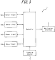
FIG. 3 is a functional block diagram illustrating the schematic configuration of an electronic device according to an embodiment. The configuration of the electronic device according to an embodiment is described below. - An
electronic device 1 according to an embodiment includes at least acontroller 3, as illustrated inFIG. 3 . The above-describedsensor 10A,sensor 10B,sensor 10C, andsensor 10D are respectively connected to thecontroller 3. Adirection detector 5 and anotification interface 7 are also connected to thecontroller 3. - To provide control and processing capability for executing various functions, the
controller 3 may include at least one processor, such as a central processing unit (CPU). Thecontroller 3 may be implemented collectively by one processor, implemented by several processors, or implemented by individual processors. The processor may be implemented as a single integrated circuit (IC). The processor may be implemented as a plurality of integrated circuits and discrete circuits communicably connected to each other. The processor may be implemented based on various other known techniques. In an embodiment, thecontroller 3 may be configured by a CPU and a program executed by the CPU. As appropriate, thecontroller 3 may include a storage, such as memory, necessary for operations by thecontroller 3. The storage may store a program executed by thecontroller 3, the result of processing executed by thecontroller 3, and the like. The storage may function as a working memory of thecontroller 3. Operations by thecontroller 3 according to an embodiment are further described below. - The
direction detector 5 detects the direction of the vehicle in which theelectronic device 1 is mounted, for example. Thedirection detector 5 may be an electronic compass or the like that detects the earth's magnetism. Thedirection detector 5 may acquire position information of the electronic device based on a global navigation satellite system (GNSS) or the like. A GNSS may include a satellite positioning system, such as global positioning system (GPS), GLONASS, Galileo, or quasi-zenith satellite system (QZSS). For example, thedirection detector 5 may have a position information acquisition device such as a GPS module included therein. In this case, thedirection detector 5 may acquire the position information of theelectronic device 1 and detect the direction of the vehicle in which theelectronic device 1 is mounted based on the change over time in the position information. Instead of or in addition to a position information acquisition device such as a GPS module, thedirection detector 5 may include a sensor such as a gyroscope. When, for example, a car navigation system is also mounted in the vehicle in which theelectronic device 1 is mounted, the direction of the vehicle may be detected from the car navigation system. - In an embodiment, the
direction detector 5 may detect whether thevehicle 100 in which theelectronic device 1 is mounted is facing north, south, east, or west, for example. Thecontroller 3 can thereby acquire (information on) the direction detected by thedirection detector 5. - The
notification interface 7 notifies the user of theelectronic device 1 or the like of information such as the result of theelectronic device 1 measuring the distance. A variety of configurations for thenotification interface 7 can be envisioned in accordance with the information of which the user is notified. For example, when notification of information such as the result of theelectronic device 1 measuring the distance is provided visually, with characters and/or images or the like, thenotification interface 7 may be a display device such as a liquid crystal display (LCD), an organic EL display, or an inorganic EL display. When notification of information such as the result of theelectronic device 1 measuring the distance is provided as more simple visual information, thenotification interface 7 may be a light-emitting device such as a light-emitting diode (LED). When notification of information such as the result of theelectronic device 1 measuring the distance is provided as audible information, such as sound or voice, thenotification interface 7 may be any speaker, buzzer, or the like. Thenotification interface 7 may be configured to include one or more of the above-described functional components. - When a predetermined object is detected within a predetermined distance around the
vehicle 100 in an embodiment, for example, thenotification interface 7 may provide corresponding notification by characters and/or an image or the like. Thenotification interface 7 may provide a display to alert the driver of thevehicle 100 when a predetermined object is detected within a predetermined distance. Thenotification interface 7 may provide notification, by characters and/or an image or the like, of the detected position of a predetermined object around thevehicle 100 when the predetermined object is detected within a predetermined distance. Furthermore, thenotification interface 7 may display the distance between a predetermined object and thevehicle 100 as a number, a diagram, or the like when the predetermined object is detected within a predetermined distance. - The
notification interface 7 in an embodiment may, for example, simply turn on a warning light when a predetermined object is detected within a predetermined distance around thevehicle 100. Furthermore, thenotification interface 7 in an embodiment may, for example, provide a predetermined warning and/or various information as audio information when a predetermined object is detected within a predetermined distance around thevehicle 100. - The
electronic device 1 according to an embodiment may include only thecontroller 3 as a minimal configuration. In addition to thecontroller 3, theelectronic device 1 according to an embodiment may also include at least one of the following, as illustrated inFIG. 3 : at least onesensor 10, thedirection detector 5, and thenotification interface 7. Theelectronic device 1 according to an embodiment can thus be configured in a variety of ways. When theelectronic device 1 according to an embodiment is mounted in thevehicle 100, then thecontroller 3, thedirection detector 5, and thenotification interface 7 may be installed at appropriate locations, such as inside thevehicle 100. In an embodiment, at least one of thecontroller 3, thedirection detector 5, and thenotification interface 7 may be installed outside thevehicle 100. - Next, the
sensor 10 according to an embodiment is described. Thesensor 10 according to an embodiment is described below as being a radar sensor that receives and transmits radio waves. -
FIG. 4 is a functional block diagram illustrating the schematic configuration of thesensor 10 according to an embodiment. With reference toFIG. 4 , thesensor 10 according to an embodiment is described below.FIG. 4 illustrates onesensor 10 as a representative example from among thesensor 10A, thesensor 10B, thesensor 10C, and thesensor 10D illustrated inFIGS. 1 to 3 . - As illustrated in
FIG. 4 , thesensor 10 according to an embodiment is, broadly speaking, configured to include atransmitter 20 and areceiver 30.FIG. 4 schematically illustrates a state in which atransmission antenna 26 of thetransmitter 20 is transmitting a transmission wave T. InFIG. 4 , the portion of the transmission wave T reflected by anobject 50 is indicated as a reflected wave R. Theobject 50 may be another vehicle other than thevehicle 100, such as thevehicle 200, or may be any other object other than thevehicle 100, such as a pedestrian or an obstacle.FIG. 4 schematically illustrates a state in which areception antenna 31 of thereceiver 30 receives the reflected waveR. A storage 12 and asynthesizer 14 illustrated inFIG. 4 may be included in thetransmitter 20, included in thereceiver 30, or be provided separately from thetransmitter 20 and thereceiver 30. - The
synthesizer 14 is an oscillator circuit that uses electronic high frequency synthesis and becomes a radar signal source. Thesynthesizer 14 may, for example, be configured by a frequency synthesizer IC, a frequency synthesizer circuit, or the like. - The
storage 12 may be a semiconductor memory, a magnetic memory, or the like. Thestorage 12 may be connected to thecontroller 3. Thestorage 12 stores various information, programs executed by thecontroller 3, and the like. Thestorage 12 may function as a working memory of thecontroller 3. Thestorage 12 may be included in thecontroller 3. - The
transmitter 20 and thereceiver 30, including thestorage 12 and thesynthesizer 14, may each have the same configuration as a known radar sensor, and the same functional components as in a known radar sensor may be used. Accordingly, a description of matter similar to a known radar sensor is simplified or omitted below. - As illustrated in
FIG. 4 , thetransmitter 20 can be configured to include aclock generator 21, asignal generator 22, aquadrature modulator 23, amixer 24, atransmission amplifier 25, and thetransmission antenna 26, for example. - In the
transmitter 20, theclock generator 21 is controlled by thecontroller 3 to generate a clock signal CLK. The clock signal generated by theclock generator 21 is supplied to thesignal generator 22. In response to control by thecontroller 3, a transmission signal sequence generated based on the direction information detected by thedirection detector 5 is assumed to be stored in thestorage 12. - The
signal generator 22 generates a transmission signal based on the clock signal generated by theclock generator 21 and a transmission signal sequence read from thestorage 12. The signal generated by thesignal generator 22 can, for example, be a radar signal in a frequency modulated continuous wave (FM-CW) method. The signal generated by thesignal generator 22 is not, however, limited to being a signal in an FM-CW method. The signal generated by thesignal generator 22 may be a signal used in various methods, such as a pulse method, a pulse compression method (spread spectrum method), or a frequency continuous wave (CW) method. The transmission signal sequences stored in thestorage 12 may differ in accordance with these methods. For example, in the case of the above-described radar signal in the FM-CW method, a signal whose frequency increases and a signal whose frequency decreases every time sample may be used. Known techniques can be used as appropriate for the above-described transmission methods. A more detailed description is therefore omitted. - The
signal generator 22 is controlled by thecontroller 3, for example, to allocate the frequency of the transmission signal when generating the transmission signal. In an embodiment, the band that thesignal generator 22 uses when allocating the frequency of the transmission signal is determined as follows. - For example, when using a millimeter wave radar in the 79 GHz band, the use of millimeter waves with a 4 GHz bandwidth, i.e. a 4 GHz band allocated from 77 GHz to 81 GHz, is prescribed. Millimeter waves with an x GHz bandwidth are also referred to below as millimeter waves of the x GHz band, where x is any number. The x GHz bandwidth is also referred to below as the x GHz band, where x is any number. In this case, a 1 GHz band, for example, can be used as a portion of the 4 GHz band allocated to the band from 77 GHz to 81 GHz. Accordingly, an operating mode in which the transmission wave T is a first band W1 in an embodiment is referred to as a "first band mode". An operating mode in which the transmission wave T is a second band W2 broader than the first band W1 in an embodiment is referred to as a "second band mode". As described above, millimeter waves of a 1 GHz band may be transmitted as the transmission wave T in the first band mode, for example. Millimeter waves of a 4 GHz band may be transmitted as the transmission wave T in the second band mode, for example. The first band mode and the second band mode are described in greater detail below. In this way, the transmission signal generated by the
signal generator 22 is supplied to thequadrature modulator 23. - The
quadrature modulator 23 performs quadrature modulation on the transmission signal supplied by thesignal generator 22. The signal subjected to quadrature modulation by thequadrature modulator 23 is supplied to themixer 24 of thetransmitter 20 and themixer 34 of thereceiver 30. - The
mixer 24 performs frequency conversion by mixing the signal subjected to quadrature modulation by thequadrature modulator 23 with the signal supplied by thesynthesizer 14 to increase the frequency of the transmission signal to the center frequency of the millimeter waves. The transmission signal subjected to frequency conversion by themixer 24 is supplied to thetransmission amplifier 25. - The
transmission amplifier 25 boosts the transmission power of the transmission signal subjected to frequency conversion by themixer 24. The transmission signal whose transmission power was boosted by thetransmission amplifier 25 is transmitted from thetransmission antenna 26 as the transmission wave T. - When an
object 50 is located within the range reached by the transmission wave T transmitted from thetransmission antenna 26, a portion of the transmission wave T is reflected by theobject 50 and becomes the reflected wave R, as illustrated inFIG. 4 . - The
receiver 30 can be configured to include thereception antenna 31, areception amplifier 32, amixer 33, themixer 34, a low-pass filter 35, an A/D converter 36, and anFFT processor 37, for example, as illustrated inFIG. 4 . - In the
receiver 30, thereception antenna 31 receives the reflected wave R. The received signal based on the reflected wave R received by thereception antenna 31 is supplied to thereception amplifier 32. Thereception amplifier 32 may be a low noise amplifier that amplifies, with low noise, the received signal supplied by thereception antenna 31. The received signal amplified by thereception amplifier 32 is supplied to themixer 33. - The
mixer 33 performs frequency conversion by mixing the received signal at an RF frequency supplied by thereception amplifier 32 with the signal supplied by thesynthesizer 14 to decrease the frequency of the received signal to an IF frequency. The received signal subjected to frequency conversion by themixer 33 is supplied to themixer 34. - The
mixer 34 generates a beat signal by multiplying the received signal subjected to frequency conversion by themixer 33 by a signal subjected to quadrature modulation by thequadrature modulator 23. The beat signal generated by themixer 34 is supplied to the low-pass filter 35. - The low-
pass filter 35 removes noise from the beat signal supplied by themixer 34. The beat signal with the noise removed therefrom by the low-pass filter 35 is supplied to the A/D converter 36. - The A/
D converter 36 may be configured by any analog to digital converter (ADC). The A/D converter 36 digitalizes the analog beat signal with the noise removed therefrom by the low-pass filter 35. The beat signal digitalized by the A/D converter 36 is supplied to theFFT processor 37. - The
FFT processor 37 may be configured by any circuit, chip, or the like that performs fast Fourier transform (FFT) processing. TheFFT processor 37 performs FFT processing on the beat signal digitalized by the A/D converter 36. The result of FFT processing by theFFT processor 37 is supplied to thecontroller 3. - The
FFT processor 37 performs the FFT processing in the above-described first band W1 or second band W2 that is broader than the first band W1. In other words, in the above-described first band mode, thesignal generator 22 generates a transmission signal in the first band W1, and theFFT processor 37 performs the FFT processing on the received signal in the first band W1. In the above-described second band mode, thesignal generator 22 generates a transmission signal in the second band W2 that is broader than the first band W1, and theFFT processor 37 performs the FFT processing on the received signal in the second band W2. - A frequency spectrum is obtained as the result of the
FFT processor 37 performing the FFT processing on the beat signal. From this frequency spectrum, thecontroller 3 can judge whether apredetermined object 50 is present in the range of the beam emitted by thesensor 10. In other words, thecontroller 3 can judge whether apredetermined object 50 is present in the range of the beam emitted by thesensor 10 based on the beat signal subjected to FFT processing. When thepredetermined object 50 is present, thecontroller 3 can also measure the distance between thesensor 10 and theobject 50 based on the beat signal subjected to FFT processing. Furthermore, when thepredetermined object 50 is present, thecontroller 3 can also judge the positional relationship between thesensor 10 and theobject 50 based on the beat signal subjected to FFT processing. In this way, the distance from anobject 50 can be measured based on the beat signal obtained from the signal transmitted as the transmission wave T and the signal received as the reflected wave R in an embodiment. An actual ranging technique for measuring distance based on a beat signal acquired using millimeter radar in the 79 GHz band, for example, is well known. A more detailed description is therefore omitted. - Next, the operations of the
electronic device 1 according to an embodiment are described. - As described above, the
electronic device 1 measures the distance from anobject 50 based on the signal transmitted as the transmission wave T and the signal that is the portion of the transmission wave T reflected by the object T and received as the reflected wave R. Theelectronic device 1 can operate in the above-described first band mode and the above-described second band mode. In the first band mode, the distance is measured using radio waves in the first band W1 that is narrower than the second band W2. Accordingly, measurement in the first band mode has a relatively small amount of power consumption for measurement but has a relatively low distance resolution during measurement. In the second band mode, on the other hand, the distance is measured using radio waves in the second band W2 that is broader than the first band W1. Accordingly, measurement in the second band mode has a relatively high distance resolution during measurement but has a relatively high amount of power consumption for measurement. In an embodiment, thecontroller 3 therefore performs control to enable switching between the first band mode and the second band mode. The operations of theelectronic device 1 according to an embodiment are described in greater detail below. Specifically, a method of switching the transmitted signal when it is judged that a reflective object is present may be adopted as a method of switching the band. The following method, for example, may be adopted as the method of judging that a reflective object is present. When an FFT is performed on a beat signal yielded by multiplying the transmission signal by the received signal, a peak appears at the frequency corresponding to the delay time thereof. A reflective object can be judged to be present when the peak is equal to or greater than a threshold. The threshold may be set in advance based on various simulations, experiments, or the like. -
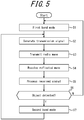
FIG. 5 is a flowchart illustrating operations of theelectronic device 1 according to an embodiment. - The process illustrated in
FIG. 5 may begin when distance is measured by theelectronic device 1, for example. - When the process illustrated in
FIG. 5 begins, thecontroller 3 first performs control to set the operating mode of theelectronic device 1 to the first band mode (step S1). In other words, thecontroller 3 sets the operating mode to an operating mode for signal generation and signal processing in the first band W1 that is a 1 GHz band, for example, in step S1. As described above, operations in the first band mode have a relatively low distance resolution during measurement but have a relatively small amount of power consumption. Accordingly, theelectronic device 1 can suppress power consumption at normal times. - After setting the operating mode to the first band mode in step S1, the
controller 3 performs control to generate the transmission signal to be transmitted from the sensor 10 (step S2). In step S2, the transmission signal is mainly generated by performing the operations described inFIG. 4 from operations by theclock generator 21 through operations by thetransmission amplifier 25 in thetransmitter 20. A further description of the matter already described with reference toFIG. 4 is omitted. - After the transmission signal is generated in step S2, the
controller 3 performs control to transmit the transmission signal from thetransmission antenna 26 as a radio wave (step S3). The radio wave is mainly transmitted in step S3 by performing the operations described inFIG. 4 from operations by thetransmission amplifier 25 through operations by thetransmission antenna 26. - When the
electronic device 1 transmits signals from a plurality ofsensors 10, thecontroller 3 may perform control in steps S2 and S3 so that the plurality ofsensors 10 transmit the signals sequentially rather than simultaneously. - After the radio waves are transmitted in step S3, the controller performs control to receive the reflected wave with the reception antenna 31 (step S4). The reflected wave is mainly received in step S4 by performing the operations described in
FIG. 4 from operations by thereception antenna 31 through operations by thereception amplifier 32 of thereceiver 30. Thereception antenna 31 receives the portion of the transmitted wave, transmitted from thetransmission antenna 26, that is reflected by theobject 50 as a reflected wave, as described above. - After the reflected wave is received in step S4, the
controller 3 performs control to process the received signal based on the received reflected wave (step S5). The received signal is mainly processed in step S5 by performing the operations described inFIG. 4 from operations by thereception amplifier 32 through operations by theFFT processor 37. The operations in step S5 enable thecontroller 3 to recognize whether apredetermined object 50 is present within a predetermined distance from thesensor 10. When apredetermined object 50 is present within a predetermined distance from thesensor 10, the operations in step S5 also enable thecontroller 3 to recognize the distance from thesensor 10 to thepredetermined object 50. Thepredetermined object 50 may be any of a variety of objects, such as a surrounding vehicle (a vehicle ahead or behind in the same lane, or an oncoming vehicle), a pedestrian, or an obstacle, as described above. - When the received signal is processed in step S5, the
controller 3 judges whether anobject 50 was detected within a predetermined distance (step S6). The predetermined distance in step S6 may, for example, be determined taking into account the distance that enables thevehicle 100 in which theelectronic device 1 is mounted to stop safely, without colliding with theobject 50. The predetermined distance may be a fixed or variable value. In general, when thevehicle 100 is an automobile or the like, the braking distance lengthens as driving speed increases. Thecontroller 3 may, for example, therefore perform control to lengthen the predetermined distance as the travel speed of thevehicle 100 in which theelectronic device 1 is mounted increases. An example of a specific technique for judging, in step S6, whether anobject 50 was detected within a predetermined distance is further described below. - When it is judged that an
object 50 was not detected within the predetermined distance in step S6, thecontroller 3 returns to step S1 and continues operations in the first band mode (distance measurement). Conversely, when it is judged that anobject 50 was detected within the predetermined distance in step S6, thecontroller 3 performs control to set operations of theelectronic device 1 to the second band mode (step S7). In other words, thecontroller 3 sets the operating mode to an operating mode for signal generation and signal processing in the second band W2 that is broader than the first band W1, such as a 4 GHz band, in step S7. As described above, operations in the second band mode have a relatively large power consumption for measurement but have a relatively high distance resolution during measurement. Accordingly, theelectronic device 1 can increase the measurement accuracy during distance measurement in this case. - After setting the mode to the second band mode in step S7, the
controller 3 performs the operations of steps S2 through S5 to transmit the transmission signal as a transmission wave and process the received signal based on the reflected wave that is received. Theelectronic device 1 can thereby increase the measurement accuracy during distance measurement. With the increased distance resolution, theelectronic device 1 in the second band mode can also simultaneously measure the distance to a plurality of objects. - In an embodiment, the
controller 3 thus performs control to enable switching between the first band mode and the second band mode. In an embodiment, thecontroller 3 performs control to switch to the second band mode when anobject 50 is detected within a predetermined distance in the first band mode. - As described above, the
electronic device 1 according to an embodiment can reduce power consumption by not normally transmitting wideband radar. Theelectronic device 1 according to an embodiment makes rough distance measurements with a relatively low distance resolution while apredetermined object 50 is not detected within a predetermined distance. Conversely, theelectronic device 1 according to an embodiment makes precise distance measurements with high distance resolution when apredetermined object 50 is detected within a predetermined distance. Therefore, theelectronic device 1 according to an embodiment can increase the efficiency of measurement without reducing the desired measurement accuracy, thereby increasing convenience. - With relation to step S6 of
FIG. 5 , the judgment of whether anobject 50 has been detected within a predetermined distance is described next in greater detail. - In general, a constant false alarm rate (CFAR) process is known as a technique for automatically detecting a target during radar signal processing. It is also known that a cell averaging (CA) CFAR process is effective when the received signal includes both a target signal and white noise such as receiver noise.
- In the
electronic device 1 according to an embodiment, theFFT processor 37 performs FFT processing on the beat signal obtained by the processing of themixer 34 illustrated inFIG. 4 , thereby obtaining a frequency spectrum, as described above. Thecontroller 3 in an embodiment may therefore judge that anobject 50 has been detected within a predetermined distance when, in the frequency spectrum obtained in this way, the ratio to the average noise intensity excluding the peak in the frequency spectrum exceeds a threshold. The average power in the frequency spectrum varies by time. Accordingly, the threshold of the ratio between the peak and the average power may be a variable threshold that varies by time. A method such as CFRA-CA (average noise power of the surrounding area excluding the neighborhood of the peak) or CRAF-OS (taking the Nth from the lowest as the noise power among the noise powers of the surrounding area excluding the neighborhood of the peak) can be used as the method of calculating the noise intensity. Known techniques can be used as appropriate for these methods. A more detailed description is therefore omitted. - In this way, the
controller 3 in an embodiment may judge that anobject 50 has been detected within a predetermined distance when the ratio between the peak in the frequency spectrum obtained based on the beat signal and the average noise intensity excluding the peak in the frequency spectrum exceeds a predetermined threshold. - Next, the first band mode according to an embodiment is described in greater detail.
- In the first band mode, the distance is measured using radio waves in the first band W1 (for example, a 1 GHz band) that is narrower than the second band W2 (for example, a 4 GHz band), as described above. When a plurality of
sensors 10 are used to measure distance in an embodiment, a different band may therefore be allocated to eachsensor 10 as the first band W1 of radio waves in the first band mode. Thevehicle 100 illustrated inFIG. 2 , for example, includes foursensors 10, i.e. thesensor 10A, thesensor 10B, thesensor 10C, and thesensor 10D. In this case, the frequency of radio waves transmitted by the foursensors 10 may, for example, be in different frequency bands. The different bands in this case may have the same bandwidth. A corresponding example is described below. -
FIG. 6 illustrates the frequency bands of transmission waves transmitted by a plurality ofsensors 10 according to an embodiment. In the first band mode according to an embodiment, a 4 GHz band allocated to the band from 77 GHz to 81 GHz may be allocated 1 GHz at a time, for example as illustrated inFIG. 6 , to the foursensors 10 illustrated inFIG. 2 . The 1 GHz band from 80 GHz to 81 GHz (frequency A) illustrated inFIG. 6 may, in other words, be allocated to the radio waves transmitted by thesensor 10A illustrated inFIG. 2 . The 1 GHz band from 79 GHz to 80 GHz (frequency B) illustrated inFIG. 6 may be allocated to the radio waves transmitted by thesensor 10B illustrated inFIG. 2 . The 1 GHz band from 78 GHz to 79 GHz (frequency C) illustrated inFIG. 6 may be allocated to the radio waves transmitted by thesensor 10C illustrated inFIG. 2 . The 1 GHz band from 77 GHz to 78 GHz (frequency D) illustrated inFIG. 6 may be allocated to the radio waves transmitted by thesensor 10D illustrated inFIG. 2 . In the example illustrated inFIG. 6 , a 4 GHz band is allocated 1 GHz at a time to the foursensors 10 illustrated inFIG. 2 . The 4 GHz band may, however, be divided into bands other than 1 GHz and is also not limited to being divided into four bands. - As described above, distance may be measured in the first band mode using radio waves in any 1 GHz band, allocated to the band from 77 GHz to 81 GHz, in each
sensor 10 among a plurality ofsensors 10. In this case, distance may be measured in the second band mode using radio waves in a 4 GHz band allocated to the band from 77 GHz to 81 GHz in at least onesensor 10 among a plurality ofsensors 10. - The
controller 3 according to an embodiment may, in the first band mode, set the first band W1 of the transmission wave T transmitted from a plurality of transmitters (sensors 10) to different bands in this way. - It is envisioned that interference might occur under limited circumstances when a plurality of vehicles in which the
electronic device 1 is mounted transmit radio waves in the first band mode after frequencies are allocated as described above. - For example, the
sensor 10A is installed in the front (travel direction) of thevehicle 100 illustrated inFIG. 2 . Thesensor 10A transmits radio waves in the 1 GHz band from 80 GHz to 81 GHz (frequency A) illustrated inFIG. 6 in the first band mode. Here, thevehicle 200 illustrated inFIG. 1 is also assumed to have the sameelectronic device 1 as thevehicle 100 mounted therein. Thesensor 10A is also installed in the front (travel direction) of thevehicle 200 in this case. Like thesensor 10A of thevehicle 100, thesensor 10A of thevehicle 200 also transmits radio waves in the 1 GHz band from 80 GHz to 81 GHz (frequency A) illustrated inFIG. 6 in the first band mode. Thevehicle 100 and thevehicle 200 are oncoming vehicles relative to each other, as illustrated inFIG. 1 . Even in this case, the problem of interference does not occur if the timing of radio wave transmission differs between thesensor 10A of thevehicle 100 and thesensor 10A of thevehicle 200. The problem of interference could occur, however, if the timing of radio wave transmission happens to overlap between thesensor 10A of thevehicle 100 and thesensor 10A of thevehicle 200. - In an embodiment, the
controller 3 may perform control so that, in theelectronic devices 1 mounted in a plurality of vehicles, the band of the radio waves transmitted by thesensor 10 installed in the same direction in the vehicles differs. This control is described below in greater detail. - As described in
FIG. 3 , thecontroller 3 of theelectronic device 1 can acquire (information on) the direction detected by thedirection detector 5. Based on the position at which eachsensor 10 among a plurality ofsensors 10 is installed in thevehicle 100, for example, thecontroller 3 can therefore identify the direction (bearing) in which eachsensor 10 transmits the transmission wave. -
FIG. 7 illustrates sensors and transmission waves according to an embodiment. As illustrated inFIG. 7 , thevehicle 100 is assumed to be traveling in the indicated travel direction (east direction), for example. Thecontroller 3 can, in this case, identify that the front of thevehicle 100 is facing east based on detection by thedirection detector 5. Thecontroller 3 can therefore identify that the direction in which thesensor 10A transmits the transmission wave is mainly east when thesensor 10A is installed at the front of thevehicle 100. Thecontroller 3 can similarly identify that thesensor 10B installed at the left side of thevehicle 100 mainly transmits the transmission wave to the north. Thecontroller 3 can similarly identify that thesensor 10C installed at the right side of thevehicle 100 mainly transmits the transmission wave to the south. Thecontroller 3 can similarly identify that thesensor 10D installed at the rear of thevehicle 100 mainly transmits the transmission wave to the west. - The
controller 3 of theelectronic device 1 mounted in thevehicle 100 may perform control so that the first band W1 of the transmission wave T transmitted by a plurality ofsensors 10 is a different band in accordance with the corresponding bearing. For example, the 1 GHz band from 80 GHz to 81 GHz (frequency A) illustrated inFIG. 6 may be allocated to the east-facingsensor 10A illustrated inFIG. 7 . The 1 GHz band from 79 GHz to 80 GHz (frequency B) illustrated inFIG. 6 may similarly be allocated to the north-facingsensor 10B illustrated inFIG. 7 . The 1 GHz band from 78 GHz to 79 GHz (frequency C) illustrated inFIG. 6 may similarly be allocated to the south-facingsensor 10C illustrated inFIG. 7 . The 1 GHz band from 77 GHz to 78 GHz (frequency D) illustrated inFIG. 6 may similarly be allocated to the west-facingsensor 10D illustrated inFIG. 7 . - In an embodiment, the same
electronic device 1 as the one mounted in thevehicle 100 may also be mounted in thevehicle 200 illustrated inFIG. 1 , for example. The same bands as for thevehicle 100 may, in this case, be allocated to the plurality ofsensors 10 installed in thevehicle 200 as well. Assuming that thevehicle 200 is facing thevehicle 100 illustrated inFIG. 7 , for example, thesensor 10 installed in the front of theoncoming vehicle 200 faces west. In this case, the 1 GHz band from 77 GHz to 78 GHz (frequency D) illustrated inFIG. 6 may be allocated to the west-facingsensor 10 installed at the front of theoncoming vehicle 200. - As a result of the above-described control, radio waves in a 1 GHz band from 80 GHz to 81 GHz (frequency A) are transmitted from the
sensor 10A installed at the front of thevehicle 100 traveling to the east. Radio waves in a 1 GHz band from 77 GHz to 78 GHz (frequency D) are transmitted from thesensor 10A installed at the front of thevehicle 200 facing thevehicle 100 and traveling to the west. The problem of interference can therefore be avoided or reduced even if the timing of radio wave transmission happens to overlap between thesensor 10A of thevehicle 100 and thesensor 10A of thevehicle 200, for example. - The
controller 3 according to an embodiment may, in the first band mode, set the first band W1 of the transmission wave T transmitted from a plurality ofsensors 10 to different bands in accordance with the direction in which the transmission wave T is transmitted. In this case, thecontroller 3 may judge the direction in which the transmission wave T is transmitted based on the direction detected by the above-describeddirection detector 5. - As described above, the
electronic device 1 according to an embodiment controls the bands of transmission waves to differ in accordance with the direction in which thesensors 10 installed in each vehicle transmit radio waves. Theelectronic device 1 according to an embodiment therefore reduces the probability of interference or mixing between radio waves transmitted bysensors 10 of a plurality of vehicles, even when the vehicles are traveling towards each other. - Although the present disclosure is based on embodiments and drawings, it is to be noted that various changes and modifications will be apparent to those skilled in the art based on the present disclosure. Therefore, such changes and modifications are to be understood as included within the scope of the present disclosure. For example, the functions and the like included in the various functional components may be reordered in any logically consistent way. A plurality of functional components may be combined into one or divided. The embodiments of the present disclosure are not limited to being implemented precisely as described and may be implemented by combining or partially omitting the features thereof as appropriate. In other words, a person of ordinary skill in the art could change or modify the matter of the present disclosure in various ways based on the present disclosure. Therefore, such changes and modifications are included within the scope of the present disclosure. For example, functional components, means, steps, or the like of each embodiment may be added to other embodiments or be replaced by functional components, means, steps, or the like of other embodiments in a logically consistent manner. A plurality of functional components, means, steps, or the like may be combined into one or divided in each embodiment. The above embodiments of the present disclosure are not limited to being implemented precisely as described and may be implemented by combining or partially omitting the features thereof.
- The above embodiments are not limited to being implemented as the
electronic device 1. For example, the above embodiments may be implemented as a control method of a device such as theelectronic device 1. Furthermore, the above embodiments may be implemented as a control program of a device such as theelectronic device 1, for example. - An example of measuring distance based on a received signal of radio waves has been described in the above embodiments. As described above, however, distance may be measured based on a received signal of an optical wave or a received signal of an audio wave in an embodiment.
-
- 1
- Electronic device
- 3
- Controller
- 5
- Direction detector
- 7
- Notification interface
- 10
- Sensor
- 12
- Storage
- 14
- Synthesizer
- 20
- Transmitter
- 21
- Clock generator
- 22
- Signal generator
- 23
- Quadrature modulator
- 24, 33, 34
- Mixer
- 25
- Transmission amplifier
- 26
- Transmission antenna
- 30
- Receiver
- 31
- Reception antenna
- 32
- Reception amplifier
- 35
- Low-pass filter
- 36
- A/D converter
- 37
- FFT processor
- 50
- Object
- 100, 200
- Vehicle
Claims (10)
- An electronic device comprising:a transmitter configured to transmit a transmission wave; anda controller configured to perform control to enable switching between a first band mode such that the transmission wave is in a first band and a second band mode such that the transmission wave is in a second band broader than the first band;wherein the controller is configured to perform control to switch to the second band mode when an object is detected within a predetermined distance in the first band mode.
- The electronic device of claim 1, wherein millimeter waves with a bandwidth of 1 gigahertz are transmitted as the transmission wave in the first band mode.
- The electronic device of claim 1 or 2, wherein millimeter waves with a bandwidth of 4 gigahertz are transmitted as the transmission wave in the second band mode.
- The electronic device of any one of claims 1 to 3, wherein the controller is configured to measure a distance to the object based on a beat signal obtained from a signal transmitted as the transmission wave and a signal received as a reflected wave, the reflected wave being a portion of the transmission wave reflected by the object.
- The electronic device of claim 4, wherein the controller is configured to judge that the object is detected within the predetermined distance when a ratio between a peak in a frequency spectrum obtained based on the beat signal and an average noise intensity excluding the peak in the frequency spectrum exceeds a predetermined threshold.
- The electronic device of any one of claims 1 to 5, wherein in the first band mode, the controller is configured to set the first band of the transmission wave transmitted from a plurality of transmitters to a different band for each transmitter.
- The electronic device of claim 6, wherein in the first band mode, the controller is configured to set the first band of the transmission wave transmitted from the plurality of transmitters to a different band in accordance with a direction of transmission of the transmission wave.
- The electronic device of claim 7, wherein the controller is configured to judge the direction of transmission of the transmission wave based on a direction detected by a direction detector.
- A control method comprising:transmitting a transmission wave; andperforming control to enable switching between a first band mode such that the transmission wave is in a first band and a second band mode such that the transmission wave is in a second band broader than the first band;wherein the control is performed to switch to the second band mode when an object is detected within a predetermined distance in the first band mode.
- A control program of an electronic device, the control program causing a computer to:transmit a transmission wave; andperform control to enable switching between a first band mode such that the transmission wave is in a first band and a second band mode such that the transmission wave is in a second band broader than the first band;wherein the control is performed to switch to the second band mode when an object is detected within a predetermined distance in the first band mode.
Applications Claiming Priority (2)
| Application Number | Priority Date | Filing Date | Title |
|---|---|---|---|
| JP2018080865A JP6637540B2 (en) | 2018-04-19 | 2018-04-19 | Electronic device, control method for electronic device, and control program for electronic device |
| PCT/JP2019/002532 WO2019202801A1 (en) | 2018-04-19 | 2019-01-25 | Electronic device, method for controlling electronic device, and program for controlling electronic device |
Publications (3)
| Publication Number | Publication Date |
|---|---|
| EP3783382A1 true EP3783382A1 (en) | 2021-02-24 |
| EP3783382A4 EP3783382A4 (en) | 2022-02-23 |
| EP3783382B1 EP3783382B1 (en) | 2026-02-25 |
Family
ID=68240223
Family Applications (1)
| Application Number | Title | Priority Date | Filing Date |
|---|---|---|---|
| EP19787755.8A Active EP3783382B1 (en) | 2018-04-19 | 2019-01-25 | Electronic device, method for controlling electronic device, and program for controlling electronic device |
Country Status (5)
| Country | Link |
|---|---|
| US (1) | US11635512B2 (en) |
| EP (1) | EP3783382B1 (en) |
| JP (1) | JP6637540B2 (en) |
| CN (1) | CN112020658A (en) |
| WO (1) | WO2019202801A1 (en) |
Families Citing this family (5)
| Publication number | Priority date | Publication date | Assignee | Title |
|---|---|---|---|---|
| CN113030974B (en) | 2019-12-25 | 2024-01-16 | 华为技术有限公司 | Detection signal transmission method, device and storage medium |
| JP7263617B2 (en) * | 2020-03-10 | 2023-04-24 | 株式会社日立国際電気 | Foreign object detection system |
| EP3904901B1 (en) * | 2020-04-28 | 2022-12-21 | Veoneer Sweden AB | A radar system for interference avoidance based on vehicle heading |
| US11978266B2 (en) * | 2020-10-21 | 2024-05-07 | Nvidia Corporation | Occupant attentiveness and cognitive load monitoring for autonomous and semi-autonomous driving applications |
| US20250269790A1 (en) * | 2024-02-23 | 2025-08-28 | Ford Global Technologies, Llc | Vehicle communications |
Family Cites Families (26)
| Publication number | Priority date | Publication date | Assignee | Title |
|---|---|---|---|---|
| DE3206916C1 (en) * | 1982-02-26 | 1983-07-07 | Standard Elektrik Lorenz Ag, 7000 Stuttgart | Radar unit |
| JPS5979176A (en) | 1982-10-27 | 1984-05-08 | Fujitsu Ten Ltd | Fm-cw radar |
| JP2909823B2 (en) | 1989-02-10 | 1999-06-23 | 本田技研工業株式会社 | FM radar equipment |
| JPH1153030A (en) | 1997-08-08 | 1999-02-26 | Nec Corp | Millimeter wave guidance device |
| JPH1183991A (en) | 1997-09-11 | 1999-03-26 | Yupiteru Ind Co Ltd | Code modulation system radar distance measuring equipment and rear under-ride protection device using the same |
| JP3613952B2 (en) | 1997-10-30 | 2005-01-26 | 三菱電機株式会社 | FM-CW radar equipment |
| JP3807663B2 (en) * | 2001-02-22 | 2006-08-09 | ユピテル工業株式会社 | On-vehicle target detection device and microwave detector |
| JP3641628B2 (en) * | 2002-10-02 | 2005-04-27 | 三菱電機株式会社 | Automotive pulse radar equipment |
| JP3909844B2 (en) * | 2003-01-30 | 2007-04-25 | 松下電器産業株式会社 | Wireless communication device |
| WO2007014333A2 (en) | 2005-07-27 | 2007-02-01 | Clariant Technologies, Corp. | Methods and apparatus for automotive radar sensors |
| JP4519797B2 (en) * | 2006-03-30 | 2010-08-04 | 富士通テン株式会社 | In-vehicle radar device and in-vehicle radar control system |
| JP4983409B2 (en) | 2007-06-04 | 2012-07-25 | 富士通株式会社 | Phase-locked oscillator and multi-radar system using the same |
| US7474254B2 (en) * | 2007-01-16 | 2009-01-06 | Innovonix, Llc. | Radar system with agile beam steering deflector |
| JP2009059200A (en) | 2007-08-31 | 2009-03-19 | Denso Corp | Driving support system |
| US7821443B2 (en) * | 2008-02-12 | 2010-10-26 | Infineon Technologies Ag | Dual mode radar methods and systems |
| JP4712826B2 (en) * | 2008-05-15 | 2011-06-29 | 古河電気工業株式会社 | Pulse Doppler radar device |
| DE102009018311A1 (en) | 2009-04-22 | 2010-10-28 | Valeo Schalter Und Sensoren Gmbh | Method and apparatus for operating a radar-based environment recognition system |
| JP5524803B2 (en) * | 2010-10-21 | 2014-06-18 | 三菱電機株式会社 | In-vehicle radar device and radio wave interference detection method for in-vehicle radar device |
| JP5633407B2 (en) * | 2011-02-04 | 2014-12-03 | 三菱電機株式会社 | Radar equipment |
| JP2013238414A (en) * | 2012-05-11 | 2013-11-28 | Honda Elesys Co Ltd | On-vehicle radar device, azimuth detection method, and azimuth detection program |
| JP2013238532A (en) | 2012-05-16 | 2013-11-28 | Mitsubishi Electric Corp | Radar device and radar system |
| JP2014081241A (en) * | 2012-10-15 | 2014-05-08 | Furuno Electric Co Ltd | Radar device and radar reception signal processing method |
| US9261590B1 (en) * | 2013-02-27 | 2016-02-16 | Google Inc. | Adaptive algorithms for interrogating the viewable scene of an automotive radar |
| WO2016204641A1 (en) * | 2015-06-17 | 2016-12-22 | Novelic D.O.O. | Millimeter-wave sensor system for parking assistance |
| FR3055049B1 (en) * | 2016-08-11 | 2018-07-27 | Thales | MULTI-RESOLUTION FMCW RADAR DETECTION METHOD AND RADAR USING SUCH A METHOD |
| JP6708099B2 (en) | 2016-11-15 | 2020-06-10 | 株式会社デンソー | Refrigeration cycle equipment |
-
2018
- 2018-04-19 JP JP2018080865A patent/JP6637540B2/en active Active
-
2019
- 2019-01-25 EP EP19787755.8A patent/EP3783382B1/en active Active
- 2019-01-25 WO PCT/JP2019/002532 patent/WO2019202801A1/en not_active Ceased
- 2019-01-25 CN CN201980024978.2A patent/CN112020658A/en active Pending
- 2019-01-25 US US17/044,426 patent/US11635512B2/en active Active
Also Published As
| Publication number | Publication date |
|---|---|
| CN112020658A (en) | 2020-12-01 |
| JP2019190880A (en) | 2019-10-31 |
| US20210033727A1 (en) | 2021-02-04 |
| JP6637540B2 (en) | 2020-01-29 |
| WO2019202801A1 (en) | 2019-10-24 |
| EP3783382A4 (en) | 2022-02-23 |
| US11635512B2 (en) | 2023-04-25 |
| EP3783382B1 (en) | 2026-02-25 |
Similar Documents
| Publication | Publication Date | Title |
|---|---|---|
| EP3783382B1 (en) | Electronic device, method for controlling electronic device, and program for controlling electronic device | |
| EP3783384A1 (en) | Electronic device, method for controlling electronic device, and program for controlling electronic device | |
| US12204045B2 (en) | Electronic device, control method of electronic device, and control program of electronic device | |
| US20220003858A1 (en) | Electronic apparatus, control method for electronic apparatus, and control program for electronic apparatus | |
| EP4166984A1 (en) | Distributed microwave radar imaging method and apparatus | |
| US12044795B2 (en) | Electronic device, control method of electronic device, and control program of electronic device | |
| EP3865907B1 (en) | Electronic device, method for controlling electronic device, and program for controlling electronic device | |
| US20210041531A1 (en) | Electronic device, control method of electronic device and control program of electronic device | |
| JP6953490B2 (en) | Electronic devices, control methods for electronic devices, and control programs for electronic devices | |
| JP6948421B2 (en) | Electronic devices, control methods for electronic devices, and control programs for electronic devices | |
| EP4043910A1 (en) | Electronic apparatus, control method for electronic apparatus, and control program for electronic apparatus | |
| EP3978954A1 (en) | Electronic device, electronic device control method, and program | |
| JP7313525B2 (en) | ELECTRONIC DEVICE, ELECTRONIC DEVICE CONTROL METHOD, AND ELECTRONIC DEVICE CONTROL PROGRAM | |
| JP2023126370A (en) | Electronic equipment, electronic equipment control method, and electronic equipment control program | |
| JP6667046B1 (en) | Electronic device, control method for electronic device, and control program for electronic device | |
| JP6948366B2 (en) | Electronic devices, control methods for electronic devices, and control programs for electronic devices | |
| JP2021193397A (en) | Electronic apparatus, method for controlling electronic apparatus, and program for controlling electronic apparatus | |
| EP3862785A1 (en) | Electronic device, electronic device control method, and electronic device control program |
Legal Events
| Date | Code | Title | Description |
|---|---|---|---|
| STAA | Information on the status of an ep patent application or granted ep patent |
Free format text: STATUS: THE INTERNATIONAL PUBLICATION HAS BEEN MADE |
|
| PUAI | Public reference made under article 153(3) epc to a published international application that has entered the european phase |
Free format text: ORIGINAL CODE: 0009012 |
|
| STAA | Information on the status of an ep patent application or granted ep patent |
Free format text: STATUS: REQUEST FOR EXAMINATION WAS MADE |
|
| 17P | Request for examination filed |
Effective date: 20201002 |
|
| AK | Designated contracting states |
Kind code of ref document: A1 Designated state(s): AL AT BE BG CH CY CZ DE DK EE ES FI FR GB GR HR HU IE IS IT LI LT LU LV MC MK MT NL NO PL PT RO RS SE SI SK SM TR |
|
| AX | Request for extension of the european patent |
Extension state: BA ME |
|
| DAV | Request for validation of the european patent (deleted) | ||
| DAX | Request for extension of the european patent (deleted) | ||
| A4 | Supplementary search report drawn up and despatched |
Effective date: 20220126 |
|
| RIC1 | Information provided on ipc code assigned before grant |
Ipc: G01S 13/931 20200101ALI20220120BHEP Ipc: G01S 13/87 20060101ALI20220120BHEP Ipc: G01S 7/35 20060101ALI20220120BHEP Ipc: G01S 7/02 20060101ALI20220120BHEP Ipc: G01S 7/282 20060101AFI20220120BHEP |
|
| P01 | Opt-out of the competence of the unified patent court (upc) registered |
Effective date: 20230505 |
|
| STAA | Information on the status of an ep patent application or granted ep patent |
Free format text: STATUS: EXAMINATION IS IN PROGRESS |
|
| 17Q | First examination report despatched |
Effective date: 20230724 |
|
| GRAP | Despatch of communication of intention to grant a patent |
Free format text: ORIGINAL CODE: EPIDOSNIGR1 |
|
| STAA | Information on the status of an ep patent application or granted ep patent |
Free format text: STATUS: GRANT OF PATENT IS INTENDED |
|
| INTG | Intention to grant announced |
Effective date: 20250916 |
|
| GRAS | Grant fee paid |
Free format text: ORIGINAL CODE: EPIDOSNIGR3 |
|
| GRAA | (expected) grant |
Free format text: ORIGINAL CODE: 0009210 |
|
| STAA | Information on the status of an ep patent application or granted ep patent |
Free format text: STATUS: THE PATENT HAS BEEN GRANTED |
|
| AK | Designated contracting states |
Kind code of ref document: B1 Designated state(s): AL AT BE BG CH CY CZ DE DK EE ES FI FR GB GR HR HU IE IS IT LI LT LU LV MC MK MT NL NO PL PT RO RS SE SI SK SM TR |
|
| REG | Reference to a national code |
Ref country code: CH Ref legal event code: F10 Free format text: ST27 STATUS EVENT CODE: U-0-0-F10-F00 (AS PROVIDED BY THE NATIONAL OFFICE) Effective date: 20260225 Ref country code: GB Ref legal event code: FG4D |
|
| REG | Reference to a national code |
Ref country code: DE Ref legal event code: R096 Ref document number: 602019081810 Country of ref document: DE |
|
| REG | Reference to a national code |
Ref country code: IE Ref legal event code: FG4D |