EP3783337A1 - Gas analyzer - Google Patents
Gas analyzer Download PDFInfo
- Publication number
- EP3783337A1 EP3783337A1 EP20183199.7A EP20183199A EP3783337A1 EP 3783337 A1 EP3783337 A1 EP 3783337A1 EP 20183199 A EP20183199 A EP 20183199A EP 3783337 A1 EP3783337 A1 EP 3783337A1
- Authority
- EP
- European Patent Office
- Prior art keywords
- gas analyzer
- gas
- measurement
- inner tube
- tube
- Prior art date
- Legal status (The legal status is an assumption and is not a legal conclusion. Google has not performed a legal analysis and makes no representation as to the accuracy of the status listed.)
- Granted
Links
Images
Classifications
-
- G—PHYSICS
- G01—MEASURING; TESTING
- G01N—INVESTIGATING OR ANALYSING MATERIALS BY DETERMINING THEIR CHEMICAL OR PHYSICAL PROPERTIES
- G01N21/00—Investigating or analysing materials by the use of optical means, i.e. using sub-millimetre waves, infrared, visible or ultraviolet light
- G01N21/17—Systems in which incident light is modified in accordance with the properties of the material investigated
- G01N21/25—Colour; Spectral properties, i.e. comparison of effect of material on the light at two or more different wavelengths or wavelength bands
- G01N21/31—Investigating relative effect of material at wavelengths characteristic of specific elements or molecules, e.g. atomic absorption spectrometry
- G01N21/39—Investigating relative effect of material at wavelengths characteristic of specific elements or molecules, e.g. atomic absorption spectrometry using tunable lasers
-
- F—MECHANICAL ENGINEERING; LIGHTING; HEATING; WEAPONS; BLASTING
- F24—HEATING; RANGES; VENTILATING
- F24H—FLUID HEATERS, e.g. WATER OR AIR HEATERS, HAVING HEAT-GENERATING MEANS, e.g. HEAT PUMPS, IN GENERAL
- F24H3/00—Air heaters
- F24H3/02—Air heaters with forced circulation
- F24H3/06—Air heaters with forced circulation the air being kept separate from the heating medium, e.g. using forced circulation of air over radiators
- F24H3/08—Air heaters with forced circulation the air being kept separate from the heating medium, e.g. using forced circulation of air over radiators by tubes
-
- G—PHYSICS
- G01—MEASURING; TESTING
- G01K—MEASURING TEMPERATURE; MEASURING QUANTITY OF HEAT; THERMALLY-SENSITIVE ELEMENTS NOT OTHERWISE PROVIDED FOR
- G01K7/00—Measuring temperature based on the use of electric or magnetic elements directly sensitive to heat ; Power supply therefor, e.g. using thermoelectric elements
- G01K7/02—Measuring temperature based on the use of electric or magnetic elements directly sensitive to heat ; Power supply therefor, e.g. using thermoelectric elements using thermoelectric elements, e.g. thermocouples
-
- G—PHYSICS
- G01—MEASURING; TESTING
- G01K—MEASURING TEMPERATURE; MEASURING QUANTITY OF HEAT; THERMALLY-SENSITIVE ELEMENTS NOT OTHERWISE PROVIDED FOR
- G01K7/00—Measuring temperature based on the use of electric or magnetic elements directly sensitive to heat ; Power supply therefor, e.g. using thermoelectric elements
- G01K7/16—Measuring temperature based on the use of electric or magnetic elements directly sensitive to heat ; Power supply therefor, e.g. using thermoelectric elements using resistive elements
-
- G—PHYSICS
- G01—MEASURING; TESTING
- G01N—INVESTIGATING OR ANALYSING MATERIALS BY DETERMINING THEIR CHEMICAL OR PHYSICAL PROPERTIES
- G01N21/00—Investigating or analysing materials by the use of optical means, i.e. using sub-millimetre waves, infrared, visible or ultraviolet light
- G01N21/01—Arrangements or apparatus for facilitating the optical investigation
-
- G—PHYSICS
- G01—MEASURING; TESTING
- G01N—INVESTIGATING OR ANALYSING MATERIALS BY DETERMINING THEIR CHEMICAL OR PHYSICAL PROPERTIES
- G01N21/00—Investigating or analysing materials by the use of optical means, i.e. using sub-millimetre waves, infrared, visible or ultraviolet light
- G01N21/01—Arrangements or apparatus for facilitating the optical investigation
- G01N21/03—Cuvette constructions
- G01N21/0332—Cuvette constructions with temperature control
-
- G—PHYSICS
- G05—CONTROLLING; REGULATING
- G05D—SYSTEMS FOR CONTROLLING OR REGULATING NON-ELECTRIC VARIABLES
- G05D23/00—Control of temperature
- G05D23/19—Control of temperature characterised by the use of electric means
- G05D23/20—Control of temperature characterised by the use of electric means with sensing elements having variation of electric or magnetic properties with change of temperature
-
- G—PHYSICS
- G01—MEASURING; TESTING
- G01N—INVESTIGATING OR ANALYSING MATERIALS BY DETERMINING THEIR CHEMICAL OR PHYSICAL PROPERTIES
- G01N21/00—Investigating or analysing materials by the use of optical means, i.e. using sub-millimetre waves, infrared, visible or ultraviolet light
- G01N21/01—Arrangements or apparatus for facilitating the optical investigation
- G01N2021/0106—General arrangement of respective parts
- G01N2021/0112—Apparatus in one mechanical, optical or electronic block
-
- G—PHYSICS
- G01—MEASURING; TESTING
- G01N—INVESTIGATING OR ANALYSING MATERIALS BY DETERMINING THEIR CHEMICAL OR PHYSICAL PROPERTIES
- G01N21/00—Investigating or analysing materials by the use of optical means, i.e. using sub-millimetre waves, infrared, visible or ultraviolet light
- G01N21/17—Systems in which incident light is modified in accordance with the properties of the material investigated
- G01N21/25—Colour; Spectral properties, i.e. comparison of effect of material on the light at two or more different wavelengths or wavelength bands
- G01N21/31—Investigating relative effect of material at wavelengths characteristic of specific elements or molecules, e.g. atomic absorption spectrometry
- G01N21/39—Investigating relative effect of material at wavelengths characteristic of specific elements or molecules, e.g. atomic absorption spectrometry using tunable lasers
- G01N2021/396—Type of laser source
- G01N2021/399—Diode laser
-
- G—PHYSICS
- G01—MEASURING; TESTING
- G01N—INVESTIGATING OR ANALYSING MATERIALS BY DETERMINING THEIR CHEMICAL OR PHYSICAL PROPERTIES
- G01N2201/00—Features of devices classified in G01N21/00
- G01N2201/06—Illumination; Optics
- G01N2201/061—Sources
- G01N2201/06113—Coherent sources; lasers
- G01N2201/0612—Laser diodes
-
- G—PHYSICS
- G01—MEASURING; TESTING
- G01N—INVESTIGATING OR ANALYSING MATERIALS BY DETERMINING THEIR CHEMICAL OR PHYSICAL PROPERTIES
- G01N2201/00—Features of devices classified in G01N21/00
- G01N2201/06—Illumination; Optics
- G01N2201/063—Illuminating optical parts
- G01N2201/0636—Reflectors
Definitions
- the present invention relates to a gas analyzer and a gas analyzer system comprising such a gas analyzer.
- a gas analyzer for measuring predetermined components in a measurement gas by irradiating, with a light, the measurement gas introduced into a measurement cell and receiving the light passing through the measurement gas is known (for example, see patent document 1).
- Such a gas analyzer may be configured such that piping is connected to a measurement gas inlet penetrating a tube constituting a measurement cell and that the measurement gas is introduced into the measurement cell through the piping.
- One or more embodiments of the present invention provide a gas analyzer capable of mitigating the influence of ambient temperature changes on the temperature of a measurement gas within a measurement cell and therefore capable of improving measurement precision.
- a gas analyzer is a gas analyzer for measuring predetermined components in a measurement gas by irradiating, with a light, the measurement gas introduced into a measurement cell and receiving the light passing through the measurement gas, configured from an inner tube constituting the measurement cell and an outer tube surrounding the inner tube, and having a double tube through which the measurement gas is introduced into the inner tube between the inner tube and the outer tube.
- the space between the inner tube and the outer tube can be used not only as a flow path for introducing the measurement gas into the inner tube, but also as a heat insulating layer. Accordingly, it is possible to mitigate the influence of ambient temperature changes on the temperature of a measurement gas within a measurement cell, and thereby it is possible to improve measurement precision.
- a gas analyzer for measuring predetermined components in a measurement gas introduced into a measurement cell by irradiating the measurement gas with light from a light emitter and receiving the light passing through the measurement gas with a light receiver as defined in claim 1 is provided.
- the light emitter and the light receiver may make part of a gas analyzer system incorporating such gas analyzer, or of the gas analyzer.
- the gas analyzer comprises a measurement cell comprising an inner tube.
- the gas analyzer further comprises an outer tube surrounding the inner tube, thus defining a double tube, and means for introducing the measurement gas into the inner tube from a space between the inner tube and the outer tube. Further embodiments of the gas analyzer are defined in the dependent claims.
- the gas analyzer may comprise a temperature adjuster (e.g., heater) for adjusting the temperature of the double tube.
- a temperature adjuster e.g., heater
- the gas analyzer may comprise a temperature adjuster (e.g., heater) for adjusting the temperature of the double tube.
- the temperature adjuster of the gas analyzer may comprise a heat insulating member (e.g., heat insulator) disposed on an outer peripheral surface of the outer peripheral pipe. According to such a configuration, it is possible to more efficiently adjust the temperature of the measurement gas before it is introduced into the inner tube.
- a heat insulating member e.g., heat insulator
- the gas analyzer may comprise the heat insulating member wound on the outer peripheral surface of the outer tube in a coil shape. According to such a configuration, it is possible to even more efficiently adjust the temperature of the measurement gas before it is introduced into the inner tube.
- the gas analyzer may comprise a heat insulating member surrounding the outer tube. According to such a configuration, it is possible to mitigate the influence of ambient temperature changes on the temperature of the measurement gas within the measurement cell.
- the measurement cell of the gas analyzer may be provided with a reflector for reflecting light and comprise an end member located at one axial end part of the double tube. According to such a configuration, it is possible to enable size reduction of the gas analyzer due to a simple configuration.
- the end member of the gas analyzer may comprise an inflow port for allowing the measurement gas to flow into a back side of the reflector from between the inner tube and the outer tube, an outflow port for allowing the measurement gas to flow into the inner tube from the back side of the reflector, and a temperature sensor disposed on the back side of the reflector.
- the temperature sensor using the temperature sensor, the temperature of the measurement gas can be directly measured near the measurement cell without obstructing the path of light, and it can be used for measurement of predetermined components in the measurement gas.
- the temperature adjuster of the gas analyzer may be configured so as to adjust the temperature of the double tube based on a value measured by the temperature sensor disposed on the back side of the reflector. According to such a configuration, by adjusting the temperature of the double tube, it is possible to precisely adjust the temperature of the measurement gas within the measurement cell.
- one axial end part of the double tube of the gas analyzer may form an introduction port for introducing the measurement gas into the inner tube from between the inner tube and the outer tube.
- the gas analyzer may be a laser gas analyzer using tunable diode laser absorption spectroscopy. According to such a configuration, it is possible to enable highly precise measurement using tunable diode laser absorption spectroscopy.
- a gas analyzer capable of mitigating the influence of ambient temperature changes on the temperature of a measurement gas within a measurement cell and therefore capable of improving measurement precision.
- a gas analyzer system may comprise a gas analyzer as defined in any of the embodiments described herein, a light emitter for irradiating light to a measurement gas introduced into the measurement cell, and a light receiver for receiving the light passing through the measurement gas.
- a gas analyzer 1 is, for example, configured to measure predetermined components in a measurement gas G using tunable diode laser absorption spectroscopy (TDLAS: tunable diode laser absorption spectroscopy) by irradiating, with a light L, the measurement gas G introduced into a measurement cell 2 and receiving the light L passing through the measurement gas G.
- TDLAS tunable diode laser absorption spectroscopy
- the gas analyzer 1 comprises an inner tube 3 making part of the measurement cell 2 and an outer tube 4 surrounding the inner tube 3.
- the inner tube 3 and outer tube 4 form a double tube 5 through which the measurement gas G is introduced into the inner tube 3 from between the inner tube 3 and the outer tube 4.
- the inner tube 3 and the outer tube 4 are each, for example, cylindrical.
- the inner tube 3 and the outer tube 4 are disposed concentrically. That is, the inner tube 3 and the outer tube 4 have a common central axis O.
- the inner tube 3 and the outer tube 4 may be disposed eccentrically.
- the measurement cell 2 is provided with a reflector 6 for reflecting the light L and comprises an end member 7 located at one axial end part 5a of the double tube 5.
- the reflector 6 is a retroreflector, but it is not limited thereto.
- the axial direction of the double tube 5 (hereinafter, also simply referred to as axial direction) means the direction along the central axis O.
- a side on which the one axial end part 5a of the double tube 5 is located with respect to another axial end part 5b of the double tube 5 (that is, the left side in FIG. 2 ) is referred to as the one axial end side, and a side opposite thereto is referred to as the other axial end side.
- an inner tube flange 8 is connected to the inner tube 3 by, for example, welding
- an outer tube flange 9 is connected to the outer tube 4 by, for example, welding.
- the outer tube flange 9 is connected to the inner tube flange 8 by a connector 10.
- the connector 10 is a bolt, but it is not limited thereto. It may be a fastener other than a bolt, and it may be a connector other than a fastener. Furthermore, these may be connected by means other than the connector 10, for example, welding or the like. However, it is preferable to configure such that the outer tube 4 can be attached to and detached from the inner tube 3 by attaching and detaching the connector 10 as a fastener. According to such a configuration, it is possible to easily maintain a flow path between the inner tube 3 and the outer tube 4 when dirtied with dust, condensation, or the like.
- a supply plug 11 for passing the measurement gas G toward the measurement cell 2 and a discharge plug 12 for passing the measurement gas G discharged from the measurement cell 2 are mounted on the inner tube flange 8. Furthermore, a supply path 13 for allowing the measurement gas G to flow from the supply plug 11 to between the inner tube 3 and the outer tube 4 is formed by a hollow portion provided in the inner tube flange 8 and an annular groove provided in the outer tube flange 9, centered around the central axis O. Moreover, a discharge path 14 for allowing the measurement gas G to flow from between the inner tube 3 and the outer tube 4 to the discharge plug 12 is formed by a hollow portion provided in the inner tube flange 8.
- the supply path for supplying the measurement gas G to between the inner tube 3 and the outer tube 4 and the discharge path for discharging the measurement gas G from between the inner tube 3 and the outer tube 4 are not limited to the foregoing configuration and can be designed as appropriate.
- the end part on the other axial end side of the measurement cell 2 comprises a window 15 mounted on the inner tube flange 8.
- the window 15 is formed from a material that transmits the light L but does not transmit the measurement gas G. Further, the window 15 is connected to an end face on the other axial end side of the inner tube flange 8 by a frame member 16 connected to the inner tube flange 8 by, for example, a connector.
- the configuration of the end part on the other axial end side of the measurement cell 2 is not limited thereto and can be designed as appropriate.
- the measurement cell 2 comprises the inner tube 3, the end member 7 (more specifically, the reflector 6, a frame 26 described later, and a middle member 25 described later), the inner tube flange 8, and the window 15.
- a sealing material such as an O-ring is disposed between the members constituting the measurement cell 2 and the like as appropriate, but is not shown in the figures.
- the gas analyzer 1 comprises an analyzer console 19 provided with a light emitting part 17 (e.g., light emitter) for irradiating the light L and a light receiving part 18 (e.g., light receiver) for receiving the light L.
- the analyzer console 19 can measure, for example, the concentration of a predetermined component in the measurement gas G based on a difference in intensity of a component of a specific wavelength between the light L emitted by the light emitting part 17 and the light L received by the light receiving part 18, that is, absorbance, an optical path length of the light L within the measurement cell 2, the temperature of the measurement gas G within the measurement cell 2, and the like.
- Examples of the predetermined component include CO, CO 2 , H 2 O, C n H m , NH 3 , O 2 , and the like.
- the end part on the one axial end side of the analyzer console 19 is connected to the inner tube flange 8 by, for example, a connector.
- the light L emitted from the light emitting part 17 passes through the window 15, proceeds through the inside of the measurement cell 2 from the other axial end side to the one axial end side, is reflected by the reflector 6, proceeds through the inside of the measurement cell 2 from the one axial end side to the other axial end side, passes through the window 15, and is received by the light receiving part 18.
- the gas analyzer 1 is not limited to comprising the reflector 6 as above and, for example, may be configured such that the light emitting part 17 and the light receiving part 18 are disposed sandwiching the measurement cell 2 in the axial direction.
- the end member 7 is provided with an inflow port 21 for allowing the measurement gas G to flow from between the inner tube 3 and the outer tube 4 into the back side of the reflector 6 and an outflow port 22 for allowing the measurement gas G to flow out from the back side of the reflector 6 into the inner tube 3.
- the temperature sensor 20 may comprise, for example, a resistance temperature detector or a thermocouple.
- the end member 7 comprises an outer member 23 connected to the end portion on the one axial end side of the outer tube 4 by, for example, welding; a middle member 25 connected to the outer member 23 by a connector 24; a frame 26 connected to the middle member 25 by, for example, fitting; and an inner member 28 connected to the middle member 25 by a connector 27.
- the end member 7 is not limited to such a member configuration.
- the outer member 23 comprises an outer cylinder 23a and an outer flange 23b extending radially outward from the end on the one axial end side of the outer cylinder 23a.
- the middle member 25 comprises a middle cylinder 25a and a middle flange 25b extending radially outward from the end on the one axial end side of the middle cylinder 25a.
- the inner member 28 comprises an inner cylinder 28a, an inner flange 28b extending radially outward from the end on the one axial end side of the inner cylinder 28a, and an end part wall 28c extending radially inward from the end on the other axial end side of the inner cylinder 28a.
- the middle cylinder 25a contacts an inner peripheral surface of the outer cylinder 23a
- an outer peripheral surface of the inner cylinder 28a contacts an inner peripheral surface of the middle cylinder 25a.
- the outer flange 23b and the middle flange 25b are connected by the connector 24, and the middle flange 25b and the inner flange 28b are connected by the connector 27.
- the connectors 24 and 27 are each a bolt, but they are not limited thereto. They may be fasteners other than bolts, and they may be connectors other than fasteners. Furthermore, these may be connected by means other than the connectors 24 and 27, for example, welding or the like.
- a unit comprising the middle member 25, the inner member 28, the frame 26, the reflector 6, and the temperature sensor 20 be attached to and detached from the outer member 23 by attaching and detaching the connector 24 as a fastener. According to such a configuration, it is possible to easily perform maintenance for removing dust and the like adhering to and accumulating on the reflector 6, which hinders measurement.
- the frame 26 is connected to the reflector 6 and holds the reflector 6.
- the inflow port 21 is formed by a notch part 21a provided on the outer peripheral surface of the frame 26 in the axial direction and a notch 21b provided at the end part on the other axial end side of the middle cylinder 25a.
- the outflow port 22 is formed by the notch part 22a provided at the end part on the one axial end side of the frame 26.
- the configuration of the inlet port 21 and the outlet port 22 is not limited thereto.
- the temperature sensor 20 is mounted on a mounting port 28d penetrating the end part wall 28c. The arrangement of the temperature sensor 20 is not limited thereto.
- a hole part may be provided penetrating the outer cylinder 23a and the middle cylinder 25a, and the temperature sensor 20 may be disposed in the hole part.
- the temperature sensor 20 it becomes necessary to go through a process of attaching and detaching the temperature sensor 20 to and from the end member 7 when attaching and detaching the unit comprising the middle member 25, the inner member 28, the frame 26, and the reflector 6 to and from the outer member 23 for maintenance of the reflector 6. Accordingly, it is preferable to dispose the temperature sensor 20 on a mounting port 28d provided on the end part wall 28c.
- the one axial end part 5a of the double tube 5 forms an introduction port 29 for introducing the measurement gas G from between the inner tube 3 and the outer tube 4 into the inner tube 3.
- the introduction port 29 comprises a gap between the inner tube 3 and the end part on the other axial end side of the middle cylinder 25a, but it is not limited thereto.
- one or more embodiments are configured to directly introduce the measurement gas G from between the inner tube 3 and the outer tube 4 into the inner tube 3 via the introduction port 29, but it is not limited thereto.
- the measurement gas G flows into the supply path 13 through the supply plug 11, passes between the inner tube 3 and the outer tube 4, and at the one axial end part 5a of the double tube 5, splits into a stream flowing into the inner tube 3 via the introduction port 29 and a stream flowing into the back side of the reflector 6 via the inlet port 21 of the end member 7.
- the measurement gas G flowing into the back side of the reflector 6 flows into the inner tube 3 via the outlet port 22.
- the measurement gas G flowing into the inner tube 3 flows through the inside of the inner tube 3 from the one axial end side toward the other axial end side, flows into the discharge path 14, and is discharged through the discharge plug 12.
- the gas analyzer 1 comprises a temperature adjuster 30 for adjusting the temperature of the double tube 5.
- the temperature adjuster 30 comprises a heating member 31 disposed on an outer peripheral surface of the outer tube 4, the above-described temperature sensor 20 for directly measuring the temperature of the measurement gas G, and a controller, not shown, for controlling the temperature of the heating member 31 based on a value measured by the temperature sensor 20.
- the heating member 31 is wound around the outer peripheral surface of the outer tube 4 in a coil shape.
- the heating member 31 comprises, for example, an electric heating element such as a heating wire or a heat exchanger such as a fluid tube through which a heating medium flows.
- the heating member 31 is not shown in FIG. 2 .
- the temperature adjuster 30 can adjust the temperature of the double tube 5 using the heating member 31, for example, such that the value measured by the temperature sensor 20 becomes a desired target value.
- the temperature of the double tube 5 is adjusted to a desired temperature, for example, 100°C or higher.
- the arrangement of the temperature sensor 20 is not limited to the back side of the reflector 6 such as described above.
- the configuration may be such that the temperature sensor 20 is disposed in the inner tube 3 to directly measure the temperature in the measurement cell 2, and the configuration may be such that the temperature sensor 20 is disposed on the outer peripheral surface of the outer tube 4 to indirectly measure the temperature in the measurement cell 2.
- the configuration may be such that a hole part is provided penetrating the double tube 5 in the radial direction and the temperature sensor 20 is disposed in the hole.
- the double tube 5 ceases to have the double tube structure in the portion where the hole is provided, and thus the function of mitigating the influence of the ambient temperature decreases accordingly.
- the double tube 5 ceases to have the double tube structure in the portion where the hole is provided, and thus the function of preheating the measurement gas G flowing between the inner tube 3 and the outer tube 4 using the heating member 31 disposed on the outer peripheral surface of the outer tube 4 before being introduced into the inner tube 3 decreases accordingly.
- the temperature sensor 20 when configuring such that the temperature sensor 20 is disposed in the foregoing hole part, it becomes necessary to go through a process for attaching and detaching the temperature sensor 20 to and from the double tube 5 when maintaining the flow path between the inner tube 3 and the outer tube 4 by attaching and detaching the outer tube 4 to and from the inner tube 3. Accordingly, it is preferable to dispose the temperature sensor 20 on the back side of the reflector 6.
- the configuration may be such that a temperature sensor for directly measuring the temperature of the double tube 5 is provided in place of or in addition to the above-described temperature sensor 20 for directly measuring the temperature of the measurement gas G and the temperature adjuster 30 comprises this temperature sensor.
- the heating member 31 is not limited to being coil-shaped. Furthermore, the heating member 31 is not limited to being disposed on the outer peripheral surface of the outer tube 4. The configuration may be such that the temperature adjuster 30 is not provided.
- the gas analyzer 1 comprises a heat insulating member 32 surrounding the outer tube 4, the heating member 31, and the end member 7.
- the heat insulating member 32 is not shown in FIG. 2 .
- the heat insulating member 32 can be made of a desired material, such as inorganic fiber or plastic foam.
- the heat insulating member 32 is preferably configured to surround the end member 7, but it may be configured to not surround the end member 7. Furthermore, the configuration may be such that the heat insulating member 32 is not provided.
Landscapes
- Physics & Mathematics (AREA)
- General Physics & Mathematics (AREA)
- Spectroscopy & Molecular Physics (AREA)
- Chemical & Material Sciences (AREA)
- Immunology (AREA)
- Pathology (AREA)
- Health & Medical Sciences (AREA)
- Life Sciences & Earth Sciences (AREA)
- Analytical Chemistry (AREA)
- Biochemistry (AREA)
- General Health & Medical Sciences (AREA)
- Engineering & Computer Science (AREA)
- Optics & Photonics (AREA)
- Thermal Sciences (AREA)
- Combustion & Propulsion (AREA)
- Mechanical Engineering (AREA)
- General Engineering & Computer Science (AREA)
- Automation & Control Theory (AREA)
- Investigating Or Analysing Materials By Optical Means (AREA)
Abstract
Description
- The present invention relates to a gas analyzer and a gas analyzer system comprising such a gas analyzer.
- A gas analyzer for measuring predetermined components in a measurement gas by irradiating, with a light, the measurement gas introduced into a measurement cell and receiving the light passing through the measurement gas is known (for example, see patent document 1). Such a gas analyzer may be configured such that piping is connected to a measurement gas inlet penetrating a tube constituting a measurement cell and that the measurement gas is introduced into the measurement cell through the piping.
- [Patent Document 1]
JP 2010-236877 A - However, when configuring as above, when the ambient temperature changes, the temperature of the measurement gas within the measurement cell changes due to the influence thereof, and as a result, there is a risk that measurement precision of predetermined components in the measurement gas will be affected.
- One or more embodiments of the present invention provide a gas analyzer capable of mitigating the influence of ambient temperature changes on the temperature of a measurement gas within a measurement cell and therefore capable of improving measurement precision.
- A gas analyzer according to one or more embodiments is a gas analyzer for measuring predetermined components in a measurement gas by irradiating, with a light, the measurement gas introduced into a measurement cell and receiving the light passing through the measurement gas, configured from an inner tube constituting the measurement cell and an outer tube surrounding the inner tube, and having a double tube through which the measurement gas is introduced into the inner tube between the inner tube and the outer tube. According to such a configuration, the space between the inner tube and the outer tube can be used not only as a flow path for introducing the measurement gas into the inner tube, but also as a heat insulating layer. Accordingly, it is possible to mitigate the influence of ambient temperature changes on the temperature of a measurement gas within a measurement cell, and thereby it is possible to improve measurement precision.
- According to one or more embodiments, a gas analyzer for measuring predetermined components in a measurement gas introduced into a measurement cell by irradiating the measurement gas with light from a light emitter and receiving the light passing through the measurement gas with a light receiver as defined in claim 1 is provided. The light emitter and the light receiver may make part of a gas analyzer system incorporating such gas analyzer, or of the gas analyzer. The gas analyzer comprises a measurement cell comprising an inner tube. The gas analyzer further comprises an outer tube surrounding the inner tube, thus defining a double tube, and means for introducing the measurement gas into the inner tube from a space between the inner tube and the outer tube. Further embodiments of the gas analyzer are defined in the dependent claims.
- In one or more embodiments, the gas analyzer may comprise a temperature adjuster (e.g., heater) for adjusting the temperature of the double tube. According to such a configuration, as it is possible to efficiently adjust the temperature of the measurement gas before it is introduced into the inner tube, it is possible to make the temperature of the measurement gas within the inner tube more uniform, and thereby it is possible to further improve measurement precision.
- In one or more embodiments, the temperature adjuster of the gas analyzer may comprise a heat insulating member (e.g., heat insulator) disposed on an outer peripheral surface of the outer peripheral pipe. According to such a configuration, it is possible to more efficiently adjust the temperature of the measurement gas before it is introduced into the inner tube.
- In one or more embodiments, in the foregoing configuration, the gas analyzer may comprise the heat insulating member wound on the outer peripheral surface of the outer tube in a coil shape. According to such a configuration, it is possible to even more efficiently adjust the temperature of the measurement gas before it is introduced into the inner tube.
- In one or more embodiments, in the foregoing configuration, the gas analyzer may comprise a heat insulating member surrounding the outer tube. According to such a configuration, it is possible to mitigate the influence of ambient temperature changes on the temperature of the measurement gas within the measurement cell.
- In one or more embodiments, in the foregoing configuration, the measurement cell of the gas analyzer may be provided with a reflector for reflecting light and comprise an end member located at one axial end part of the double tube. According to such a configuration, it is possible to enable size reduction of the gas analyzer due to a simple configuration.
- In one or more embodiments, in the foregoing configuration, the end member of the gas analyzer may comprise an inflow port for allowing the measurement gas to flow into a back side of the reflector from between the inner tube and the outer tube, an outflow port for allowing the measurement gas to flow into the inner tube from the back side of the reflector, and a temperature sensor disposed on the back side of the reflector. According to such a configuration, using the temperature sensor, the temperature of the measurement gas can be directly measured near the measurement cell without obstructing the path of light, and it can be used for measurement of predetermined components in the measurement gas. Furthermore, by providing not only an inflow port, but also an outflow port, it is possible to control gas retention within the end member, and thus it is possible to make the distribution of predetermined components in the measurement gas within the measurement cell more uniform. Accordingly, it is possible to further improve measurement precision.
- In one or more embodiments, in the foregoing configuration, the temperature adjuster of the gas analyzer may be configured so as to adjust the temperature of the double tube based on a value measured by the temperature sensor disposed on the back side of the reflector. According to such a configuration, by adjusting the temperature of the double tube, it is possible to precisely adjust the temperature of the measurement gas within the measurement cell.
- In one or more embodiments, in the foregoing configuration, one axial end part of the double tube of the gas analyzer may form an introduction port for introducing the measurement gas into the inner tube from between the inner tube and the outer tube. According to such a configuration, as it is possible to smoothly introduce the measurement gas into the inner tube from the introduction port, it is possible to make the temperature distribution of the measurement gas within the measurement cell more uniform, and thereby it is possible to further improve measurement precision.
- In one or more embodiments, in the foregoing configuration, the gas analyzer may be a laser gas analyzer using tunable diode laser absorption spectroscopy. According to such a configuration, it is possible to enable highly precise measurement using tunable diode laser absorption spectroscopy.
- According to one or more embodiments of the present invention, it is possible to provide a gas analyzer capable of mitigating the influence of ambient temperature changes on the temperature of a measurement gas within a measurement cell and therefore capable of improving measurement precision.
- According to one or more embodiments, a gas analyzer system is provided. The gas analyzer system may comprise a gas analyzer as defined in any of the embodiments described herein, a light emitter for irradiating light to a measurement gas introduced into the measurement cell, and a light receiver for receiving the light passing through the measurement gas.
-
-
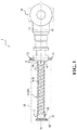
FIG. 1 is a planar view illustrating a gas analyzer according to one or more embodiments. -
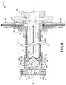
FIG. 2 is a cross-sectional view illustrating a portion of the gas analyzer illustrated inFIG. 1 . - Embodiments of the present invention will be exemplified and described in detail below with reference to the drawings.
- As illustrated in
FIG. 1 andFIG. 2 , a gas analyzer 1 according to one or more embodiments is, for example, configured to measure predetermined components in a measurement gas G using tunable diode laser absorption spectroscopy (TDLAS: tunable diode laser absorption spectroscopy) by irradiating, with a light L, the measurement gas G introduced into ameasurement cell 2 and receiving the light L passing through the measurement gas G. - The gas analyzer 1 comprises an
inner tube 3 making part of themeasurement cell 2 and anouter tube 4 surrounding theinner tube 3. Theinner tube 3 andouter tube 4 form adouble tube 5 through which the measurement gas G is introduced into theinner tube 3 from between theinner tube 3 and theouter tube 4. Theinner tube 3 and theouter tube 4 are each, for example, cylindrical. Theinner tube 3 and theouter tube 4 are disposed concentrically. That is, theinner tube 3 and theouter tube 4 have a common central axis O. Theinner tube 3 and theouter tube 4 may be disposed eccentrically. - Furthermore, the
measurement cell 2 is provided with areflector 6 for reflecting the light L and comprises an end member 7 located at oneaxial end part 5a of thedouble tube 5. Thereflector 6 is a retroreflector, but it is not limited thereto. In one or more embodiments, the axial direction of the double tube 5 (hereinafter, also simply referred to as axial direction) means the direction along the central axis O. Furthermore, in one or more embodiments, a side on which the oneaxial end part 5a of thedouble tube 5 is located with respect to anotheraxial end part 5b of the double tube 5 (that is, the left side inFIG. 2 ) is referred to as the one axial end side, and a side opposite thereto is referred to as the other axial end side. - In the other
axial end part 5b of thedouble tube 5, an inner tube flange 8 is connected to theinner tube 3 by, for example, welding, and an outer tube flange 9 is connected to theouter tube 4 by, for example, welding. The outer tube flange 9 is connected to the inner tube flange 8 by aconnector 10. Theconnector 10 is a bolt, but it is not limited thereto. It may be a fastener other than a bolt, and it may be a connector other than a fastener. Furthermore, these may be connected by means other than theconnector 10, for example, welding or the like. However, it is preferable to configure such that theouter tube 4 can be attached to and detached from theinner tube 3 by attaching and detaching theconnector 10 as a fastener. According to such a configuration, it is possible to easily maintain a flow path between theinner tube 3 and theouter tube 4 when dirtied with dust, condensation, or the like. - A
supply plug 11 for passing the measurement gas G toward themeasurement cell 2 and adischarge plug 12 for passing the measurement gas G discharged from themeasurement cell 2 are mounted on the inner tube flange 8. Furthermore, asupply path 13 for allowing the measurement gas G to flow from thesupply plug 11 to between theinner tube 3 and theouter tube 4 is formed by a hollow portion provided in the inner tube flange 8 and an annular groove provided in the outer tube flange 9, centered around the central axis O. Moreover, adischarge path 14 for allowing the measurement gas G to flow from between theinner tube 3 and theouter tube 4 to thedischarge plug 12 is formed by a hollow portion provided in the inner tube flange 8. The supply path for supplying the measurement gas G to between theinner tube 3 and theouter tube 4 and the discharge path for discharging the measurement gas G from between theinner tube 3 and theouter tube 4 are not limited to the foregoing configuration and can be designed as appropriate. - The end part on the other axial end side of the
measurement cell 2 comprises awindow 15 mounted on the inner tube flange 8. Thewindow 15 is formed from a material that transmits the light L but does not transmit the measurement gas G. Further, thewindow 15 is connected to an end face on the other axial end side of the inner tube flange 8 by aframe member 16 connected to the inner tube flange 8 by, for example, a connector. The configuration of the end part on the other axial end side of themeasurement cell 2 is not limited thereto and can be designed as appropriate. As described above, in one or more embodiments, themeasurement cell 2 comprises theinner tube 3, the end member 7 (more specifically, thereflector 6, aframe 26 described later, and amiddle member 25 described later), the inner tube flange 8, and thewindow 15. A sealing material such as an O-ring is disposed between the members constituting themeasurement cell 2 and the like as appropriate, but is not shown in the figures. - The gas analyzer 1 comprises an
analyzer console 19 provided with a light emitting part 17 (e.g., light emitter) for irradiating the light L and a light receiving part 18 (e.g., light receiver) for receiving the light L. For example, theanalyzer console 19 can measure, for example, the concentration of a predetermined component in the measurement gas G based on a difference in intensity of a component of a specific wavelength between the light L emitted by the light emitting part 17 and the light L received by the light receiving part 18, that is, absorbance, an optical path length of the light L within themeasurement cell 2, the temperature of the measurement gas G within themeasurement cell 2, and the like. Examples of the predetermined component include CO, CO2, H2O, CnHm, NH3, O2, and the like. The end part on the one axial end side of theanalyzer console 19 is connected to the inner tube flange 8 by, for example, a connector. - As indicated by the outlined arrow in
FIG. 2 , the light L emitted from the light emitting part 17 passes through thewindow 15, proceeds through the inside of themeasurement cell 2 from the other axial end side to the one axial end side, is reflected by thereflector 6, proceeds through the inside of themeasurement cell 2 from the one axial end side to the other axial end side, passes through thewindow 15, and is received by the light receiving part 18. - The gas analyzer 1 is not limited to comprising the
reflector 6 as above and, for example, may be configured such that the light emitting part 17 and the light receiving part 18 are disposed sandwiching themeasurement cell 2 in the axial direction. - In order to precisely measure, for example, the concentration of the predetermined component in the measurement gas G, it is preferable to directly measure the temperature of the measurement gas G near the
measurement cell 2. Thus, in one or more embodiments, along with disposing atemperature sensor 20 on a back side of thereflector 6, the end member 7 is provided with aninflow port 21 for allowing the measurement gas G to flow from between theinner tube 3 and theouter tube 4 into the back side of thereflector 6 and an outflow port 22 for allowing the measurement gas G to flow out from the back side of thereflector 6 into theinner tube 3. Thetemperature sensor 20 may comprise, for example, a resistance temperature detector or a thermocouple. - The end member 7 comprises an
outer member 23 connected to the end portion on the one axial end side of theouter tube 4 by, for example, welding; amiddle member 25 connected to theouter member 23 by aconnector 24; aframe 26 connected to themiddle member 25 by, for example, fitting; and aninner member 28 connected to themiddle member 25 by aconnector 27. The end member 7 is not limited to such a member configuration. - The
outer member 23 comprises anouter cylinder 23a and anouter flange 23b extending radially outward from the end on the one axial end side of theouter cylinder 23a. Themiddle member 25 comprises amiddle cylinder 25a and amiddle flange 25b extending radially outward from the end on the one axial end side of themiddle cylinder 25a. Theinner member 28 comprises aninner cylinder 28a, aninner flange 28b extending radially outward from the end on the one axial end side of theinner cylinder 28a, and anend part wall 28c extending radially inward from the end on the other axial end side of theinner cylinder 28a. An outer peripheral surface of themiddle cylinder 25a contacts an inner peripheral surface of theouter cylinder 23a, and an outer peripheral surface of theinner cylinder 28a contacts an inner peripheral surface of themiddle cylinder 25a. Theouter flange 23b and themiddle flange 25b are connected by theconnector 24, and themiddle flange 25b and theinner flange 28b are connected by theconnector 27. Theconnectors connectors middle member 25, theinner member 28, theframe 26, thereflector 6, and thetemperature sensor 20 be attached to and detached from theouter member 23 by attaching and detaching theconnector 24 as a fastener. According to such a configuration, it is possible to easily perform maintenance for removing dust and the like adhering to and accumulating on thereflector 6, which hinders measurement. - The
frame 26 is connected to thereflector 6 and holds thereflector 6. Theinflow port 21 is formed by anotch part 21a provided on the outer peripheral surface of theframe 26 in the axial direction and anotch 21b provided at the end part on the other axial end side of themiddle cylinder 25a. Furthermore, the outflow port 22 is formed by thenotch part 22a provided at the end part on the one axial end side of theframe 26. The configuration of theinlet port 21 and the outlet port 22 is not limited thereto. Thetemperature sensor 20 is mounted on a mountingport 28d penetrating theend part wall 28c. The arrangement of thetemperature sensor 20 is not limited thereto. For example, a hole part may be provided penetrating theouter cylinder 23a and themiddle cylinder 25a, and thetemperature sensor 20 may be disposed in the hole part. However, in this case, it becomes necessary to go through a process of attaching and detaching thetemperature sensor 20 to and from the end member 7 when attaching and detaching the unit comprising themiddle member 25, theinner member 28, theframe 26, and thereflector 6 to and from theouter member 23 for maintenance of thereflector 6. Accordingly, it is preferable to dispose thetemperature sensor 20 on a mountingport 28d provided on theend part wall 28c. - The one
axial end part 5a of thedouble tube 5 forms anintroduction port 29 for introducing the measurement gas G from between theinner tube 3 and theouter tube 4 into theinner tube 3. Theintroduction port 29 comprises a gap between theinner tube 3 and the end part on the other axial end side of themiddle cylinder 25a, but it is not limited thereto. Furthermore, one or more embodiments are configured to directly introduce the measurement gas G from between theinner tube 3 and theouter tube 4 into theinner tube 3 via theintroduction port 29, but it is not limited thereto. - The measurement gas G flows into the
supply path 13 through thesupply plug 11, passes between theinner tube 3 and theouter tube 4, and at the oneaxial end part 5a of thedouble tube 5, splits into a stream flowing into theinner tube 3 via theintroduction port 29 and a stream flowing into the back side of thereflector 6 via theinlet port 21 of the end member 7. The measurement gas G flowing into the back side of thereflector 6 flows into theinner tube 3 via the outlet port 22. The measurement gas G flowing into theinner tube 3 flows through the inside of theinner tube 3 from the one axial end side toward the other axial end side, flows into thedischarge path 14, and is discharged through thedischarge plug 12. - The gas analyzer 1 comprises a
temperature adjuster 30 for adjusting the temperature of thedouble tube 5. Thetemperature adjuster 30 comprises aheating member 31 disposed on an outer peripheral surface of theouter tube 4, the above-describedtemperature sensor 20 for directly measuring the temperature of the measurement gas G, and a controller, not shown, for controlling the temperature of theheating member 31 based on a value measured by thetemperature sensor 20. Theheating member 31 is wound around the outer peripheral surface of theouter tube 4 in a coil shape. Theheating member 31 comprises, for example, an electric heating element such as a heating wire or a heat exchanger such as a fluid tube through which a heating medium flows. Theheating member 31 is not shown inFIG. 2 . Thetemperature adjuster 30 can adjust the temperature of thedouble tube 5 using theheating member 31, for example, such that the value measured by thetemperature sensor 20 becomes a desired target value. The temperature of thedouble tube 5 is adjusted to a desired temperature, for example, 100°C or higher. - The arrangement of the
temperature sensor 20 is not limited to the back side of thereflector 6 such as described above. For example, the configuration may be such that thetemperature sensor 20 is disposed in theinner tube 3 to directly measure the temperature in themeasurement cell 2, and the configuration may be such that thetemperature sensor 20 is disposed on the outer peripheral surface of theouter tube 4 to indirectly measure the temperature in themeasurement cell 2. When disposing thetemperature sensor 20 within theinner tube 3, the configuration may be such that a hole part is provided penetrating thedouble tube 5 in the radial direction and thetemperature sensor 20 is disposed in the hole. However, in this case, thedouble tube 5 ceases to have the double tube structure in the portion where the hole is provided, and thus the function of mitigating the influence of the ambient temperature decreases accordingly. Furthermore, thedouble tube 5 ceases to have the double tube structure in the portion where the hole is provided, and thus the function of preheating the measurement gas G flowing between theinner tube 3 and theouter tube 4 using theheating member 31 disposed on the outer peripheral surface of theouter tube 4 before being introduced into theinner tube 3 decreases accordingly. Moreover, when configuring such that thetemperature sensor 20 is disposed in the foregoing hole part, it becomes necessary to go through a process for attaching and detaching thetemperature sensor 20 to and from thedouble tube 5 when maintaining the flow path between theinner tube 3 and theouter tube 4 by attaching and detaching theouter tube 4 to and from theinner tube 3. Accordingly, it is preferable to dispose thetemperature sensor 20 on the back side of thereflector 6. - The configuration may be such that a temperature sensor for directly measuring the temperature of the
double tube 5 is provided in place of or in addition to the above-describedtemperature sensor 20 for directly measuring the temperature of the measurement gas G and thetemperature adjuster 30 comprises this temperature sensor. Theheating member 31 is not limited to being coil-shaped. Furthermore, theheating member 31 is not limited to being disposed on the outer peripheral surface of theouter tube 4. The configuration may be such that thetemperature adjuster 30 is not provided. - The gas analyzer 1 comprises a
heat insulating member 32 surrounding theouter tube 4, theheating member 31, and the end member 7. Theheat insulating member 32 is not shown inFIG. 2 . Theheat insulating member 32 can be made of a desired material, such as inorganic fiber or plastic foam. Theheat insulating member 32 is preferably configured to surround the end member 7, but it may be configured to not surround the end member 7. Furthermore, the configuration may be such that theheat insulating member 32 is not provided. - Although the disclosure has been described with respect to only a limited number of embodiments, those skilled in the art, having benefit of this disclosure, will appreciate that various other embodiments may be devised without departing from the scope of the present invention. Accordingly, the scope of the invention should be limited only by the attached claims.
-
- 1
- Gas analyzer
- 2
- Measurement cell
- 3
- Inner tube
- 4
- Outer tube
- 5
- Double tube
- 5a
- One axial end part of double tube
- 5b
- Other axial end part of double tube
- 6
- Reflector
- 7
- End member
- 8
- Inner tube flange
- 9
- Outer tube flange
- 10
- Connector
- 11
- Supply plug
- 12
- Discharge plug
- 13
- Supply path
- 14
- Discharge path
- 15
- Window
- 16
- Frame member
- 17
- Light emitting part
- 18
- Light receiving part
- 19
- Analyzer console
- 20
- Temperature sensor
- 21
- Inflow port
- 21a, 21b
- Notch part
- 22
- Outflow port
- 22a
- Notch part
- 23
- Outer member
- 23a
- Outer cylinder
- 23b
- Outer flange
- 24
- Fastener
- 25
- Middle member
- 25a
- Middle cylinder
- 25b
- Middle flange
- 26
- Frame
- 27
- Connector
- 28
- Inner member
- 28a
- Inner cylinder
- 28b
- Inner flange
- 28c
- End part wall
- 28d
- Mounting port
- 29
- Introduction port
- 30
- Temperature adjuster
- 31
- Heating member
- 32
- Heat insulating member
- G
- Measurement gas
- L
- Light
- O
- Central axis
Claims (15)
- A gas analyzer for measuring predetermined components in a measurement gas introduced into a measurement cell by irradiating the measurement gas with light from a light emitter and receiving the light passing through the measurement gas with a light receiver, the gas analyzer comprising:a measurement cell comprising an inner tube; andan outer tube surrounding the inner tube; andmeans for introducing the measurement gas into the inner tube from a space between the inner tube and the outer tube.
- The gas analyzer according to claim 1, further comprising:
a temperature adjuster configured to adjust a temperature of the inner and outer tube. - The gas analyzer according to claim 2, wherein the temperature adjuster is disposed on an outer peripheral surface of the outer tube.
- The gas analyzer according to claim 3, wherein the temperature adjuster is wound around the outer peripheral surface in a coil shape.
- The gas analyzer according to any one of claims 2-4, wherein the temperature adjuster comprises a heating wire.
- The gas analyzer according to claim 2, wherein the temperature adjuster comprises a fluid tube disposed around the outer tube.
- The gas analyzer according to any one of claims 1-6, further comprising:
a heat insulator surrounding the outer tube. - The gas analyzer according to any one of claims 1-7, wherein the measurement cell further comprises:a reflector configured to reflect the light, andwherein the means for introducing the measurement gas into the inner tube comprises an end member disposed at one axial end part of the inner tube and the outer tube.
- The gas analyzer according to claim 8, wherein the reflector is a retroreflector.
- The gas analyzer according to claim 8 or claim 9, wherein the reflector is disposed in the end member.
- The gas analyzer according to any one of claims 8-10, wherein the end member further comprises:an inflow port configured to let the measurement gas flow towards a back side of the reflector from between the inner tube and the outer tube and;an outflow port configured to let the measurement gas flow into into the inner tube from the back side of the reflector; anda temperature sensor disposed on the back side of the reflector.
- The gas analyzer according to claim 11, wherein the reflector is disposed between the temperature sensor and the inflow and outflow ports.
- The gas analyzer according to any one of claims 8-12, wherein the one axial end part of the inner tube and outer tube forms an introduction port configured to introduce the measurement gas into the inner tube from between the inner tube and the outer tube.
- The gas analyzer according to any one of claims 1-13, wherein the gas analyzer is a laser gas analyzer configured to use tunable diode laser absorption spectroscopy.
- A gas analyzer system comprising a gas analyzer as defined in any one of claims 1-14, a light emitter for irradiating light to a measurement gas introduced into the measurement cell, and a light receiver for receiving the light passing through the measurement gas.
Applications Claiming Priority (1)
| Application Number | Priority Date | Filing Date | Title |
|---|---|---|---|
| JP2019149998A JP7099416B2 (en) | 2019-08-19 | 2019-08-19 | Gas analyzer |
Publications (2)
| Publication Number | Publication Date |
|---|---|
| EP3783337A1 true EP3783337A1 (en) | 2021-02-24 |
| EP3783337B1 EP3783337B1 (en) | 2023-08-02 |
Family
ID=71409213
Family Applications (1)
| Application Number | Title | Priority Date | Filing Date |
|---|---|---|---|
| EP20183199.7A Active EP3783337B1 (en) | 2019-08-19 | 2020-06-30 | Gas analyzer |
Country Status (4)
| Country | Link |
|---|---|
| US (1) | US20210055214A1 (en) |
| EP (1) | EP3783337B1 (en) |
| JP (1) | JP7099416B2 (en) |
| CN (1) | CN112394046A (en) |
Citations (4)
| Publication number | Priority date | Publication date | Assignee | Title |
|---|---|---|---|---|
| EP1724567A1 (en) * | 2005-05-17 | 2006-11-22 | Nitrex Metal Inc | Apparatus and method for controlling atmospheres in heat treating of metals |
| JP2010236877A (en) | 2009-03-30 | 2010-10-21 | Chubu Electric Power Co Inc | Apparatus and method for measuring ammonia concentration in exhaust gas |
| WO2010146079A1 (en) * | 2009-06-19 | 2010-12-23 | Siemens Aktiengesellschaft | Heatable flow-through measuring cell |
| WO2012126469A1 (en) * | 2011-03-23 | 2012-09-27 | Danfoss Ixa A/S | Gas sensor with vortex |
Family Cites Families (7)
| Publication number | Priority date | Publication date | Assignee | Title |
|---|---|---|---|---|
| JPS52159277U (en) * | 1976-05-28 | 1977-12-03 | ||
| JPS5619008Y2 (en) * | 1977-05-19 | 1981-05-06 | ||
| JPS60344A (en) * | 1983-06-15 | 1985-01-05 | Fujitsu Ltd | Optical device |
| JP2002267102A (en) * | 2001-03-07 | 2002-09-18 | Mitsubishi Heavy Ind Ltd | Electric evaporator |
| JP2011013126A (en) * | 2009-07-03 | 2011-01-20 | Shimadzu Corp | Gas concentration measuring instrument |
| DE102016101720A1 (en) * | 2016-02-01 | 2017-08-03 | Sick Ag | Device for optical in situ gas analysis |
| DE202017001743U1 (en) * | 2017-03-31 | 2017-05-08 | Siemens Aktiengesellschaft | Gas analyzer |
-
2019
- 2019-08-19 JP JP2019149998A patent/JP7099416B2/en active Active
-
2020
- 2020-06-30 EP EP20183199.7A patent/EP3783337B1/en active Active
- 2020-07-06 US US16/921,022 patent/US20210055214A1/en not_active Abandoned
- 2020-07-10 CN CN202010661392.1A patent/CN112394046A/en active Pending
Patent Citations (4)
| Publication number | Priority date | Publication date | Assignee | Title |
|---|---|---|---|---|
| EP1724567A1 (en) * | 2005-05-17 | 2006-11-22 | Nitrex Metal Inc | Apparatus and method for controlling atmospheres in heat treating of metals |
| JP2010236877A (en) | 2009-03-30 | 2010-10-21 | Chubu Electric Power Co Inc | Apparatus and method for measuring ammonia concentration in exhaust gas |
| WO2010146079A1 (en) * | 2009-06-19 | 2010-12-23 | Siemens Aktiengesellschaft | Heatable flow-through measuring cell |
| WO2012126469A1 (en) * | 2011-03-23 | 2012-09-27 | Danfoss Ixa A/S | Gas sensor with vortex |
Also Published As
| Publication number | Publication date |
|---|---|
| CN112394046A (en) | 2021-02-23 |
| US20210055214A1 (en) | 2021-02-25 |
| JP7099416B2 (en) | 2022-07-12 |
| JP2021032597A (en) | 2021-03-01 |
| EP3783337B1 (en) | 2023-08-02 |
Similar Documents
| Publication | Publication Date | Title |
|---|---|---|
| TWI684082B (en) | Small volume, long pathlength multi-pass gas cell for ir and uv monitoring | |
| EP1998164B1 (en) | Exhaust gas analyzer comprising a sensor unit | |
| EP2993461B1 (en) | Gas cell assembly for absorption spectroscopy | |
| US10222091B2 (en) | Next generation modular heating system | |
| US9863813B2 (en) | Flame sensor | |
| CN106164648B (en) | Device for determining the concentration of at least one gas in a sample gas stream by means of infrared absorption spectroscopy | |
| US9377411B2 (en) | Transflexion probe and transflective sensor | |
| US20220003686A1 (en) | Probe suitable for measuring the composition of an oxidising gas | |
| AU2004290273A1 (en) | Method and device for detecting water vapor within natural gas | |
| CN104977273A (en) | Attachment and Alignment Device for Optical Sources, Detectors and Analysers, and Modular Analysis System | |
| US10930530B2 (en) | Methods and apparatus for wafer temperature measurement | |
| US20190085444A1 (en) | Concentration control apparatus and material gas supply system | |
| US20190242818A1 (en) | Absorbance meter and semiconductor manufacturing device using absorbance meter | |
| CN113348360B (en) | High temperature optical probe | |
| CN107167428B (en) | Absorption tank for gas detection | |
| US9568372B2 (en) | Apparatus for calibrating pyrometer | |
| CA2758398A1 (en) | Device for determining the water content of a target | |
| CN106537117B (en) | Probe for gas sensor with gas separation sampling gas flow | |
| US20190160459A1 (en) | Fluid analyzer manifold and techniques | |
| US20030090666A1 (en) | Gas permeable probe for use in an optical analyzer for an exhaust gas stream flowing through a duct or chimney | |
| US20210055214A1 (en) | Gas analyzer | |
| CN105466855B (en) | Sample detection means based on Herriott multiple reflecting pool | |
| CN207095731U (en) | Transmit thermometric detector | |
| CN110637225A (en) | Optical sensor | |
| US9500530B2 (en) | Apparatus for calibrating pyrometer |
Legal Events
| Date | Code | Title | Description |
|---|---|---|---|
| PUAI | Public reference made under article 153(3) epc to a published international application that has entered the european phase |
Free format text: ORIGINAL CODE: 0009012 |
|
| STAA | Information on the status of an ep patent application or granted ep patent |
Free format text: STATUS: THE APPLICATION HAS BEEN PUBLISHED |
|
| AK | Designated contracting states |
Kind code of ref document: A1 Designated state(s): AL AT BE BG CH CY CZ DE DK EE ES FI FR GB GR HR HU IE IS IT LI LT LU LV MC MK MT NL NO PL PT RO RS SE SI SK SM TR |
|
| AX | Request for extension of the european patent |
Extension state: BA ME |
|
| STAA | Information on the status of an ep patent application or granted ep patent |
Free format text: STATUS: REQUEST FOR EXAMINATION WAS MADE |
|
| 17P | Request for examination filed |
Effective date: 20210820 |
|
| RBV | Designated contracting states (corrected) |
Designated state(s): AL AT BE BG CH CY CZ DE DK EE ES FI FR GB GR HR HU IE IS IT LI LT LU LV MC MK MT NL NO PL PT RO RS SE SI SK SM TR |
|
| GRAP | Despatch of communication of intention to grant a patent |
Free format text: ORIGINAL CODE: EPIDOSNIGR1 |
|
| STAA | Information on the status of an ep patent application or granted ep patent |
Free format text: STATUS: GRANT OF PATENT IS INTENDED |
|
| RIC1 | Information provided on ipc code assigned before grant |
Ipc: G01N 21/39 20060101ALI20230206BHEP Ipc: G01N 21/03 20060101AFI20230206BHEP |
|
| INTG | Intention to grant announced |
Effective date: 20230227 |
|
| GRAS | Grant fee paid |
Free format text: ORIGINAL CODE: EPIDOSNIGR3 |
|
| GRAA | (expected) grant |
Free format text: ORIGINAL CODE: 0009210 |
|
| STAA | Information on the status of an ep patent application or granted ep patent |
Free format text: STATUS: THE PATENT HAS BEEN GRANTED |
|
| P01 | Opt-out of the competence of the unified patent court (upc) registered |
Effective date: 20230603 |
|
| AK | Designated contracting states |
Kind code of ref document: B1 Designated state(s): AL AT BE BG CH CY CZ DE DK EE ES FI FR GB GR HR HU IE IS IT LI LT LU LV MC MK MT NL NO PL PT RO RS SE SI SK SM TR |
|
| REG | Reference to a national code |
Ref country code: GB Ref legal event code: FG4D |
|
| REG | Reference to a national code |
Ref country code: CH Ref legal event code: EP |
|
| REG | Reference to a national code |
Ref country code: DE Ref legal event code: R096 Ref document number: 602020014793 Country of ref document: DE |
|
| REG | Reference to a national code |
Ref country code: IE Ref legal event code: FG4D |
|
| REG | Reference to a national code |
Ref country code: LT Ref legal event code: MG9D |
|
| REG | Reference to a national code |
Ref country code: NL Ref legal event code: MP Effective date: 20230802 |
|
| REG | Reference to a national code |
Ref country code: AT Ref legal event code: MK05 Ref document number: 1595322 Country of ref document: AT Kind code of ref document: T Effective date: 20230802 |
|
| PG25 | Lapsed in a contracting state [announced via postgrant information from national office to epo] |
Ref country code: GR Free format text: LAPSE BECAUSE OF FAILURE TO SUBMIT A TRANSLATION OF THE DESCRIPTION OR TO PAY THE FEE WITHIN THE PRESCRIBED TIME-LIMIT Effective date: 20231103 |
|
| PG25 | Lapsed in a contracting state [announced via postgrant information from national office to epo] |
Ref country code: IS Free format text: LAPSE BECAUSE OF FAILURE TO SUBMIT A TRANSLATION OF THE DESCRIPTION OR TO PAY THE FEE WITHIN THE PRESCRIBED TIME-LIMIT Effective date: 20231202 |
|
| PG25 | Lapsed in a contracting state [announced via postgrant information from national office to epo] |
Ref country code: SE Free format text: LAPSE BECAUSE OF FAILURE TO SUBMIT A TRANSLATION OF THE DESCRIPTION OR TO PAY THE FEE WITHIN THE PRESCRIBED TIME-LIMIT Effective date: 20230802 Ref country code: RS Free format text: LAPSE BECAUSE OF FAILURE TO SUBMIT A TRANSLATION OF THE DESCRIPTION OR TO PAY THE FEE WITHIN THE PRESCRIBED TIME-LIMIT Effective date: 20230802 Ref country code: PT Free format text: LAPSE BECAUSE OF FAILURE TO SUBMIT A TRANSLATION OF THE DESCRIPTION OR TO PAY THE FEE WITHIN THE PRESCRIBED TIME-LIMIT Effective date: 20231204 Ref country code: NO Free format text: LAPSE BECAUSE OF FAILURE TO SUBMIT A TRANSLATION OF THE DESCRIPTION OR TO PAY THE FEE WITHIN THE PRESCRIBED TIME-LIMIT Effective date: 20231102 Ref country code: NL Free format text: LAPSE BECAUSE OF FAILURE TO SUBMIT A TRANSLATION OF THE DESCRIPTION OR TO PAY THE FEE WITHIN THE PRESCRIBED TIME-LIMIT Effective date: 20230802 Ref country code: LV Free format text: LAPSE BECAUSE OF FAILURE TO SUBMIT A TRANSLATION OF THE DESCRIPTION OR TO PAY THE FEE WITHIN THE PRESCRIBED TIME-LIMIT Effective date: 20230802 Ref country code: LT Free format text: LAPSE BECAUSE OF FAILURE TO SUBMIT A TRANSLATION OF THE DESCRIPTION OR TO PAY THE FEE WITHIN THE PRESCRIBED TIME-LIMIT Effective date: 20230802 Ref country code: IS Free format text: LAPSE BECAUSE OF FAILURE TO SUBMIT A TRANSLATION OF THE DESCRIPTION OR TO PAY THE FEE WITHIN THE PRESCRIBED TIME-LIMIT Effective date: 20231202 Ref country code: HR Free format text: LAPSE BECAUSE OF FAILURE TO SUBMIT A TRANSLATION OF THE DESCRIPTION OR TO PAY THE FEE WITHIN THE PRESCRIBED TIME-LIMIT Effective date: 20230802 Ref country code: GR Free format text: LAPSE BECAUSE OF FAILURE TO SUBMIT A TRANSLATION OF THE DESCRIPTION OR TO PAY THE FEE WITHIN THE PRESCRIBED TIME-LIMIT Effective date: 20231103 Ref country code: FI Free format text: LAPSE BECAUSE OF FAILURE TO SUBMIT A TRANSLATION OF THE DESCRIPTION OR TO PAY THE FEE WITHIN THE PRESCRIBED TIME-LIMIT Effective date: 20230802 Ref country code: AT Free format text: LAPSE BECAUSE OF FAILURE TO SUBMIT A TRANSLATION OF THE DESCRIPTION OR TO PAY THE FEE WITHIN THE PRESCRIBED TIME-LIMIT Effective date: 20230802 |
|
| PG25 | Lapsed in a contracting state [announced via postgrant information from national office to epo] |
Ref country code: PL Free format text: LAPSE BECAUSE OF FAILURE TO SUBMIT A TRANSLATION OF THE DESCRIPTION OR TO PAY THE FEE WITHIN THE PRESCRIBED TIME-LIMIT Effective date: 20230802 |
|
| PG25 | Lapsed in a contracting state [announced via postgrant information from national office to epo] |
Ref country code: ES Free format text: LAPSE BECAUSE OF FAILURE TO SUBMIT A TRANSLATION OF THE DESCRIPTION OR TO PAY THE FEE WITHIN THE PRESCRIBED TIME-LIMIT Effective date: 20230802 |
|
| PG25 | Lapsed in a contracting state [announced via postgrant information from national office to epo] |
Ref country code: SM Free format text: LAPSE BECAUSE OF FAILURE TO SUBMIT A TRANSLATION OF THE DESCRIPTION OR TO PAY THE FEE WITHIN THE PRESCRIBED TIME-LIMIT Effective date: 20230802 Ref country code: RO Free format text: LAPSE BECAUSE OF FAILURE TO SUBMIT A TRANSLATION OF THE DESCRIPTION OR TO PAY THE FEE WITHIN THE PRESCRIBED TIME-LIMIT Effective date: 20230802 Ref country code: ES Free format text: LAPSE BECAUSE OF FAILURE TO SUBMIT A TRANSLATION OF THE DESCRIPTION OR TO PAY THE FEE WITHIN THE PRESCRIBED TIME-LIMIT Effective date: 20230802 Ref country code: EE Free format text: LAPSE BECAUSE OF FAILURE TO SUBMIT A TRANSLATION OF THE DESCRIPTION OR TO PAY THE FEE WITHIN THE PRESCRIBED TIME-LIMIT Effective date: 20230802 Ref country code: DK Free format text: LAPSE BECAUSE OF FAILURE TO SUBMIT A TRANSLATION OF THE DESCRIPTION OR TO PAY THE FEE WITHIN THE PRESCRIBED TIME-LIMIT Effective date: 20230802 Ref country code: CZ Free format text: LAPSE BECAUSE OF FAILURE TO SUBMIT A TRANSLATION OF THE DESCRIPTION OR TO PAY THE FEE WITHIN THE PRESCRIBED TIME-LIMIT Effective date: 20230802 Ref country code: SK Free format text: LAPSE BECAUSE OF FAILURE TO SUBMIT A TRANSLATION OF THE DESCRIPTION OR TO PAY THE FEE WITHIN THE PRESCRIBED TIME-LIMIT Effective date: 20230802 |
|
| REG | Reference to a national code |
Ref country code: DE Ref legal event code: R097 Ref document number: 602020014793 Country of ref document: DE |
|
| PG25 | Lapsed in a contracting state [announced via postgrant information from national office to epo] |
Ref country code: IT Free format text: LAPSE BECAUSE OF FAILURE TO SUBMIT A TRANSLATION OF THE DESCRIPTION OR TO PAY THE FEE WITHIN THE PRESCRIBED TIME-LIMIT Effective date: 20230802 |
|
| PLBE | No opposition filed within time limit |
Free format text: ORIGINAL CODE: 0009261 |
|
| STAA | Information on the status of an ep patent application or granted ep patent |
Free format text: STATUS: NO OPPOSITION FILED WITHIN TIME LIMIT |
|
| 26N | No opposition filed |
Effective date: 20240503 |
|
| PG25 | Lapsed in a contracting state [announced via postgrant information from national office to epo] |
Ref country code: SI Free format text: LAPSE BECAUSE OF FAILURE TO SUBMIT A TRANSLATION OF THE DESCRIPTION OR TO PAY THE FEE WITHIN THE PRESCRIBED TIME-LIMIT Effective date: 20230802 |
|
| PG25 | Lapsed in a contracting state [announced via postgrant information from national office to epo] |
Ref country code: BG Free format text: LAPSE BECAUSE OF FAILURE TO SUBMIT A TRANSLATION OF THE DESCRIPTION OR TO PAY THE FEE WITHIN THE PRESCRIBED TIME-LIMIT Effective date: 20230802 |
|
| PG25 | Lapsed in a contracting state [announced via postgrant information from national office to epo] |
Ref country code: BG Free format text: LAPSE BECAUSE OF FAILURE TO SUBMIT A TRANSLATION OF THE DESCRIPTION OR TO PAY THE FEE WITHIN THE PRESCRIBED TIME-LIMIT Effective date: 20230802 |
|
| PG25 | Lapsed in a contracting state [announced via postgrant information from national office to epo] |
Ref country code: MC Free format text: LAPSE BECAUSE OF FAILURE TO SUBMIT A TRANSLATION OF THE DESCRIPTION OR TO PAY THE FEE WITHIN THE PRESCRIBED TIME-LIMIT Effective date: 20230802 |
|
| REG | Reference to a national code |
Ref country code: CH Ref legal event code: PL |
|
| PG25 | Lapsed in a contracting state [announced via postgrant information from national office to epo] |
Ref country code: LU Free format text: LAPSE BECAUSE OF NON-PAYMENT OF DUE FEES Effective date: 20240630 |
|
| GBPC | Gb: european patent ceased through non-payment of renewal fee |
Effective date: 20240630 |
|
| PG25 | Lapsed in a contracting state [announced via postgrant information from national office to epo] |
Ref country code: IE Free format text: LAPSE BECAUSE OF NON-PAYMENT OF DUE FEES Effective date: 20240630 |
|
| PG25 | Lapsed in a contracting state [announced via postgrant information from national office to epo] |
Ref country code: BE Free format text: LAPSE BECAUSE OF NON-PAYMENT OF DUE FEES Effective date: 20240630 Ref country code: CH Free format text: LAPSE BECAUSE OF NON-PAYMENT OF DUE FEES Effective date: 20240630 |
|
| PG25 | Lapsed in a contracting state [announced via postgrant information from national office to epo] |
Ref country code: FR Free format text: LAPSE BECAUSE OF NON-PAYMENT OF DUE FEES Effective date: 20240630 |
|
| PG25 | Lapsed in a contracting state [announced via postgrant information from national office to epo] |
Ref country code: GB Free format text: LAPSE BECAUSE OF NON-PAYMENT OF DUE FEES Effective date: 20240630 |
|
| REG | Reference to a national code |
Ref country code: BE Ref legal event code: MM Effective date: 20240630 |
|
| PGFP | Annual fee paid to national office [announced via postgrant information from national office to epo] |
Ref country code: DE Payment date: 20250520 Year of fee payment: 6 |
|
| PG25 | Lapsed in a contracting state [announced via postgrant information from national office to epo] |
Ref country code: CY Free format text: LAPSE BECAUSE OF FAILURE TO SUBMIT A TRANSLATION OF THE DESCRIPTION OR TO PAY THE FEE WITHIN THE PRESCRIBED TIME-LIMIT; INVALID AB INITIO Effective date: 20200630 |
|
| PG25 | Lapsed in a contracting state [announced via postgrant information from national office to epo] |
Ref country code: HU Free format text: LAPSE BECAUSE OF FAILURE TO SUBMIT A TRANSLATION OF THE DESCRIPTION OR TO PAY THE FEE WITHIN THE PRESCRIBED TIME-LIMIT; INVALID AB INITIO Effective date: 20200630 |