EP3783333B1 - Charakterisierung einer wolken-atmosphäre unter verwendung von in zwei winkeln rückgestreutem licht - Google Patents
Charakterisierung einer wolken-atmosphäre unter verwendung von in zwei winkeln rückgestreutem licht Download PDFInfo
- Publication number
- EP3783333B1 EP3783333B1 EP19216111.5A EP19216111A EP3783333B1 EP 3783333 B1 EP3783333 B1 EP 3783333B1 EP 19216111 A EP19216111 A EP 19216111A EP 3783333 B1 EP3783333 B1 EP 3783333B1
- Authority
- EP
- European Patent Office
- Prior art keywords
- cloud
- optical
- cloud atmosphere
- atmosphere
- detector
- Prior art date
- Legal status (The legal status is an assumption and is not a legal conclusion. Google has not performed a legal analysis and makes no representation as to the accuracy of the status listed.)
- Active
Links
Images





Classifications
-
- G—PHYSICS
- G01—MEASURING; TESTING
- G01S—RADIO DIRECTION-FINDING; RADIO NAVIGATION; DETERMINING DISTANCE OR VELOCITY BY USE OF RADIO WAVES; LOCATING OR PRESENCE-DETECTING BY USE OF THE REFLECTION OR RERADIATION OF RADIO WAVES; ANALOGOUS ARRANGEMENTS USING OTHER WAVES
- G01S17/00—Systems using the reflection or reradiation of electromagnetic waves other than radio waves, e.g. lidar systems
- G01S17/88—Lidar systems specially adapted for specific applications
- G01S17/95—Lidar systems specially adapted for specific applications for meteorological use
-
- B—PERFORMING OPERATIONS; TRANSPORTING
- B64—AIRCRAFT; AVIATION; COSMONAUTICS
- B64D—EQUIPMENT FOR FITTING IN OR TO AIRCRAFT; FLIGHT SUITS; PARACHUTES; ARRANGEMENT OR MOUNTING OF POWER PLANTS OR PROPULSION TRANSMISSIONS IN AIRCRAFT
- B64D45/00—Aircraft indicators or protectors not otherwise provided for
-
- G—PHYSICS
- G01—MEASURING; TESTING
- G01S—RADIO DIRECTION-FINDING; RADIO NAVIGATION; DETERMINING DISTANCE OR VELOCITY BY USE OF RADIO WAVES; LOCATING OR PRESENCE-DETECTING BY USE OF THE REFLECTION OR RERADIATION OF RADIO WAVES; ANALOGOUS ARRANGEMENTS USING OTHER WAVES
- G01S17/00—Systems using the reflection or reradiation of electromagnetic waves other than radio waves, e.g. lidar systems
- G01S17/66—Tracking systems using electromagnetic waves other than radio waves
-
- B—PERFORMING OPERATIONS; TRANSPORTING
- B64—AIRCRAFT; AVIATION; COSMONAUTICS
- B64D—EQUIPMENT FOR FITTING IN OR TO AIRCRAFT; FLIGHT SUITS; PARACHUTES; ARRANGEMENT OR MOUNTING OF POWER PLANTS OR PROPULSION TRANSMISSIONS IN AIRCRAFT
- B64D15/00—De-icing or preventing icing on exterior surfaces of aircraft
-
- G—PHYSICS
- G01—MEASURING; TESTING
- G01N—INVESTIGATING OR ANALYSING MATERIALS BY DETERMINING THEIR CHEMICAL OR PHYSICAL PROPERTIES
- G01N15/00—Investigating characteristics of particles; Investigating permeability, pore-volume or surface-area of porous materials
- G01N15/02—Investigating particle size or size distribution
- G01N15/0205—Investigating particle size or size distribution by optical means
- G01N15/0211—Investigating a scatter or diffraction pattern
-
- G—PHYSICS
- G08—SIGNALLING
- G08G—TRAFFIC CONTROL SYSTEMS
- G08G5/00—Traffic control systems for aircraft
- G08G5/70—Arrangements for monitoring traffic-related situations or conditions
- G08G5/76—Arrangements for monitoring traffic-related situations or conditions for monitoring atmospheric conditions
-
- B—PERFORMING OPERATIONS; TRANSPORTING
- B64—AIRCRAFT; AVIATION; COSMONAUTICS
- B64D—EQUIPMENT FOR FITTING IN OR TO AIRCRAFT; FLIGHT SUITS; PARACHUTES; ARRANGEMENT OR MOUNTING OF POWER PLANTS OR PROPULSION TRANSMISSIONS IN AIRCRAFT
- B64D15/00—De-icing or preventing icing on exterior surfaces of aircraft
- B64D15/20—Means for detecting icing or initiating de-icing
-
- G—PHYSICS
- G01—MEASURING; TESTING
- G01N—INVESTIGATING OR ANALYSING MATERIALS BY DETERMINING THEIR CHEMICAL OR PHYSICAL PROPERTIES
- G01N15/00—Investigating characteristics of particles; Investigating permeability, pore-volume or surface-area of porous materials
- G01N2015/0023—Investigating dispersion of liquids
- G01N2015/0026—Investigating dispersion of liquids in gas, e.g. fog
-
- G—PHYSICS
- G01—MEASURING; TESTING
- G01N—INVESTIGATING OR ANALYSING MATERIALS BY DETERMINING THEIR CHEMICAL OR PHYSICAL PROPERTIES
- G01N21/00—Investigating or analysing materials by the use of optical means, i.e. using sub-millimetre waves, infrared, visible or ultraviolet light
- G01N21/17—Systems in which incident light is modified in accordance with the properties of the material investigated
- G01N21/25—Colour; Spectral properties, i.e. comparison of effect of material on the light at two or more different wavelengths or wavelength bands
- G01N21/31—Investigating relative effect of material at wavelengths characteristic of specific elements or molecules, e.g. atomic absorption spectrometry
- G01N21/39—Investigating relative effect of material at wavelengths characteristic of specific elements or molecules, e.g. atomic absorption spectrometry using tunable lasers
- G01N2021/392—Measuring reradiation, e.g. fluorescence, backscatter
-
- Y—GENERAL TAGGING OF NEW TECHNOLOGICAL DEVELOPMENTS; GENERAL TAGGING OF CROSS-SECTIONAL TECHNOLOGIES SPANNING OVER SEVERAL SECTIONS OF THE IPC; TECHNICAL SUBJECTS COVERED BY FORMER USPC CROSS-REFERENCE ART COLLECTIONS [XRACs] AND DIGESTS
- Y02—TECHNOLOGIES OR APPLICATIONS FOR MITIGATION OR ADAPTATION AGAINST CLIMATE CHANGE
- Y02A—TECHNOLOGIES FOR ADAPTATION TO CLIMATE CHANGE
- Y02A90/00—Technologies having an indirect contribution to adaptation to climate change
- Y02A90/10—Information and communication technologies [ICT] supporting adaptation to climate change, e.g. for weather forecasting or climate simulation
Definitions
- Super-cooled small water droplets tend to form ice only on leading edges of an aircraft's exterior surface.
- Super-cooled Large water Droplets SLDs
- SLDs Super-cooled Large water Droplets
- Ice that forms on unprotected surface regions can severely alter the aerodynamics of the aircraft. Such ice accretion may cause aircraft stall or result in unpredictable aircraft control variation that might lead to flight issues.
- ice can form on control surfaces and/or lift surfaces.
- Apparatus and associated method relate to a system for characterizing a cloud atmosphere.
- the system is provided as claimed in claim 1 and the method is provided as claimed in claim 11.
- Some embodiments relate to a method for characterizing a cloud atmosphere.
- the method is provided as claimed in claim 11.
- Apparatus and associated methods relate to determining an effective size, quantity, shape, and type of water particles in a cloud atmosphere based on differences in amplitudes of optical signals backscattered at different backscattering angles.
- Off-axis backscattering - backscattering at angles other than 180 degrees - is affected by the effective size, quantity, shape, and type of water particles.
- a ratio of detected amplitudes of optical signals that are backscattered at different angles is used to indicate the effective size, quantity, shape, and type of water particles in the cloud atmosphere.
- optical emitters and detectors are configured to measure amplitudes of optical signals backscattered at backscattering angles of both on-axis - 180 degrees - and off-axis varieties.
- FIG. 1 is a schematic view of an aircraft equipped to measure an effective size of liquid droplets in a cloud atmosphere.
- aircraft 10 is traveling through cloud atmosphere 12.
- Aircraft 10 is equipped with cloud conditions measurement system 14 that is shown probing cloud atmosphere 12 by projecting optical beam 16 along emission axis 18 into cloud atmosphere 12.
- Optical beam 16 projects from an optical emitter aligned with emission axis 18.
- Pulsed beam 16 is then backscattered by liquid water droplets and/or ice crystals of cloud atmosphere 12.
- cloud conditions measurement system 14 is shown receiving first and second portions 20 and 22 backscattered with backscattering angles ⁇ 1 and ⁇ 2 respectively.
- Cloud conditions measurement system 14 has optical detectors configured to detect portions 20 and 22 backscattered with backscattering angles ⁇ 1 and ⁇ 2 respectively, by cloud atmosphere 12. Cloud conditions measurement system 14 can calculate cloud parameters based on detector signals indicative of backscattered portions 20 and 22 received by cloud conditions measurement system 14.
- Optical beam 16 can be projected into cloud atmosphere 12 within a field of view centered on a principal emission direction, which is collinear with emission axis 18.
- the emission field of view can be within an emission angle threshold of the principal emission direction.
- the emission field of view can be +/- 0.25°, 0.5°, 1°, 2°, or 3°, for example.
- Portions 20 and 22 backscattered by liquid water droplets and/or ice crystals within a projection volume of cloud atmosphere 12 are those portions falling within detection fields of view of the optical detectors of cloud conditions measurement system 14.
- the detection fields of view can be centered on principal detection directions, which are directed so that the detection fields of view intersect the emission field of view.
- the detection fields of view can be within detection angle thresholds of the principal detection directions.
- Angles between the principle emission direction and the principle detection directions can determine the backscattering angles ⁇ 1 and ⁇ 2 that are measureable. Any light detected by the optical detectors is backscattered by liquid water particles and/or ice crystals from within intersecting volumes of the emission field of view and the detection fields of view. The optical detectors can then generate electrical signals corresponding to the detected light backscattered by cloud atmosphere 12. These generated electrical signals are indicative of various metrics of cloud atmosphere 12.
- the effective size, quantity, shape, and type of water droplets and/or ice crystals determines how an optical beam can be backscattered thereby. For example, relatively large-sized water droplets preferentially backscatter an optical beam directly - with a backscatter angle of 180°. Smaller sizes of water droplets permit a greater percentage of light to be backscattered at in an off-axis fashion - less than 180°. Thus, the relationship between the electrical signals generated by optical detectors that are configured to detect backscatter with different backscattering angles is indicative of the effective size of the water particles that backscattered the optical beam.
- FIG. 2 is a schematic diagram of a system for determining an effective size of water particles in a cloud atmosphere using optical signals backscattered at two different backscattered angles.
- cloud conditions measurement system 14 has optical emitter 24, first optical detector 26 and second optical detector 28.
- Optical emitter 24 is shown projecting optical beam within emission field of view FOV EMIT centered on a principal emission direction, which is collinear with emission axis 18.
- First detection field of view FOV DET1 is depicted as being centered on a first detection direction, which is collinear with first detection axis 30.
- First detection axis 30 and emission axis 18 are shown as being substantially parallel to one another. Such a configuration permits detection of portions of an emitted optical beam that are directly backscattered ( i.e., with a backscattering angle of 180°).
- Second Detection field of view FOV DET2 is depicted as being centered on a second detection direction, which is collinear with second detection axis 32. Second detection axis 32 and emission axis 18 are shown as being at angle ⁇ 2 with respect to one another. Such a configuration permits detection of portions of an emitted optical beam that are backscattered in an off-axis fashion ( i.e., with a backscattering angle less than 180°). In the depicted embodiment, the off-axis orientation of second optical detector 28 is determined by detector aligner 34, such as an optical wedge or prism, aligned with second optical detector 28, according to the present invention.
- detector aligner 34 such as an optical wedge or prism
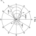
- FIG. 3 is a normalized polar diagram of scattering amplitude as a function of scattering angle for different effective size water particles.
- Polar diagram 36 include scattering amplitude/angle relations 38, 40 and 42 corresponding to effective sizes ( e.g., diameters) of water particles 0.5, 5 and 50 ⁇ m.
- Mie scattering becomes an operative scattering mechanism. Mie scattering produces a pattern like an antenna lobe, with a more intense forward lobe and less intense backscattering lobe for larger particles.
- Scattering amplitude/angle relation 40 is indicative of particles in the Mie scattering regime.
- Scattering amplitude/angle relation 42 has a forward lobe that is significantly larger than its backscattering lobe.
- Mie scattering determines multi-lobed fine structure in the polar diagram of scattering amplitude for spherical particles as a function of scattering angle.
- the FIG. 3 polar diagram does not depict such multi-lobed fine structure, because of the polydispese size distributions of cloud atmospheres.
- Such various multi-lobed fine structures when combined in a composite polar diagram of scattering amplitude as a function of scattering angle, can result in a smoothing of these various fine structures, as depicted in FIG. 3 .
- the angular scattering profile albeit different from the depicted Mie scattering profiles, can be used to obtain effective size information as well.
- FIG. 4 is a schematic diagram of the system depicted in FIG. 2 showing intersecting emitter and detector fields of view.
- emitter field of view FOV EMIT and first detector field of view FOV DET1 are shown intersecting one another.
- First optical detector 26 is located a first distance di in a first direction transverse from the principal emission direction from optical emitter 24.
- First optical detector 26 and has first detection field of view FOV DET1 intercepting emission field of view FOV EMIT .
- First detection field of view FOV DET1 is centered upon a first principle detection direction, which is collinear with first detection axis 30. The principle emission direction and the first principle detection direction determine the first backscatter angle.
- the intersection of emitter field of view FOV EMIT and first detection field of view FOV DET1 begins at a distance or range Ri from optical emitter 24 and first optical detector 26.
- Range Ri of the intersecting volumes of emitter field of view FOV EMIT and first detection field of view FOV DET1 is determined based on: i) the distance d1 separating optical emitter 24 and first optical detector 26; ii) angle ⁇ 1 between the principle emission direction and the first principle detection direction; and iii) diverging angles 2 ⁇ EMIT and 2 ⁇ DET1 of emitter field of view FOV EMIT and first detection field of view FOV DET1 , respectively.
- the distance or range R 2 from optical emitter 24 and second optical detector 28 is determined based on the corresponding parameters of second optical detector 28.
- the intersecting volumes will have approximately the same range, and other embodiments, the intersecting volumes will have dissimilar ranges.
- the distance d 2 between optical emitter 24 and second optical detector 28 will be greater than the distance di between optical emitter 24 and first optical detector 26 so as to nominally equalize the ranges R 1 and R 2 to the intersecting volumes.
- the intersecting volumes associated with optical detectors 26 and 28 will necessarily be different due to the differences in the orientation of first and second detection axes 30 and 32.
- Backscattering will begin at the ranges of the intersecting volumes, and continue throughout the intersecting volumes. As backscattering occurs, however, attenuation of the optical beam emitted into the cloud atmosphere also occurs.
- the differences between the intersecting volumes at great distances can be less consequential than differences in the ranges, at which point attenuation of the optical signal can be modest.
- the portion of the light backscattered within the intersecting volume that is detectable by first optical detector 26 will have a distribution of backscattering angles nominally centered on angle ⁇ 1 , which is the angle between the principle emission direction and the first principle detection direction. There will be a distribution about the nominal backscattering angle ⁇ 1 due to diverging angles 2 ⁇ EMIT and 2 ⁇ DET1 of emitter field of view FOV EMIT and first detection field of view FOV DET1 .
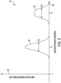
- FIG. 5 is a graph depicting the backscattering angles that are detectable using the system depicted in FIG. 2 .
- graph 44 includes horizontal axis 46 and vertical axis 48.
- Horizontal axis 46 is indicative of backscattering angle (degrees).
- Vertical axis 48 is indicative of amplitude of light backscattered by a cloud atmosphere as detected by first and second optical detectors 26 and 28.
- Amplitude/angle relation 50 indicates the amplitude/angle relation corresponding to the signal sensed by first optical detector 26.
- First optical detector 26 will generate a signal indicative of the integrated area under amplitude/angle relation 50.
- Amplitude/angle relation 52 indicates the amplitude/angle relation corresponding to the signal sensed by second optical detector 28.
- Second optical detector 28 will generate a signal indicative of the integrated area under amplitude/angle relation 52.
- Amplitude/angle relations 50 and 52 provide visualization of the distribution of backscattering angles that are detectable by first and second optical detectors 26 and 28,
- FIG. 6 is a graph depicting a relationship between the off-axis/direct backscatter ratio to effective size of water particles in a cloud atmosphere.
- graph 54 includes horizontal axis 56 and vertical axis 58.
- Horizontal axis 56 is indicative of effective size in ⁇ m ( e.g., effective diameter) of water particles in a cloud atmosphere.
- Vertical axis 58 is indicative of the ratio of signal amplitudes of second and first optical detectors 28 and 26.
- the ratio of second and first optical detectors 28 and 26 is indicative of the ratio of off-axis backscattering (detectable by second optical detector 28) to direct backscattering (detectable by first optical detector 26).
- a difference of detected amplitudes of optical signals that are backscattered at different angles is used to indicate the effective size, quantity, shape, and type of water particles in the cloud atmosphere.
- other embodiments may include optical devices within the path of the optical receiver to split the optical signal into its various polarization states to provide further discrimination of cloud particles.
- Graph 54 also depicts simulation results 60 (i.e., ratio of off-axis to direct backscattering) of various cloud atmospheres.
- the various cloud atmospheres characterized by an effective droplet size can have different types of drop size distributions, which are responsible for the breadth of simulation results 60.
- a clear trend in simulation results 60 can be seen despite the breadth of simulation results 60.
- a curve can be fit to this data, for example, and the fit curve can be used to determine an effective size of water particles in a cloud atmosphere based on the ratio of signals detected by second and first optical detectors 28 and 26.
- FIG. 7 is a block diagram of an embodiment of a system for determining an effective size of water particles in a cloud atmosphere using optical signals backscattered at two different backscattered angles.
- cloud conditions measurement system 14 includes controller 62, optical emitter 24, and first and second optical detectors 26 and 28.
- Optical emitter 24 is configured to emit an optical beam into cloud atmosphere 12.
- Each of first and second optical detectors 26 and 28 is configured to detect a portion of the emitted optical beam backscattered by cloud atmosphere 12.
- First optical detector 26 is configured to detect light backscattered by cloud atmosphere 12 with nominal backscattering angle ⁇ 1 .
- Second optical detector 28 is configured to detect light backscattered by cloud atmosphere 12 with nominal backscattering angle ⁇ 2 .
- Controller 62 includes processor(s) 64, optical transceiver interface 66, storage device(s) 68, aircraft interface 70, and user interface 72.
- Processor(s) 64 can receive program instructions 68P from storage device(s) 68.
- Processor(s) 64 can be configured to control cloud conditions measurement system 14, based on received program instructions 68P.
- processor(s) 64 can be configured to send optical transceiver interface 66 a signal that causes optical emitter 24 to emit an optical beam. The emitted optical beam is directed into cloud atmosphere 12.
- First and second optical detectors 26 and 28 are configured to generate signals indicative of portions of the emitted optical beam backscattered by cloud atmosphere 12.
- Optical transceiver interface 66 provides an electrical interface between controller 62 and the optical transceivers: optical emitter 24 and optical detectors 26 and 28.
- Processor(s) 64 receives, from optical transceiver interface 66, signals indicative of the detected portions of the emitted optical beam backscattered by cloud atmosphere 12.
- Processor(s) 64 can then determine particle characteristics of cloud atmosphere 12 based on the signals received from optical transceiver interface 66.
- Processor(s) 64 can compare the determined particle characteristics with predetermined thresholds to determine if the cloud atmosphere has water particles that could cause severe icing, for example. If, for example, one or more of the determined particle characteristics exceeds a predetermined threshold, processor(s) 64 can generate an alert signal and send the generated alert signal to aircraft interface 70. In some embodiments, processor(s) 64 can store and/or log the associated parameter values in data memory 68D. In some embodiments, processor(s) 64 may interface with other input and output devices via user interface 72.
- controller 62 includes processor(s) 64, optical transceiver interface 66, storage device(s) 68, aircraft interface 70, and user interface 72.
- controller 62 can include more or fewer components.
- controller 62 may not include user interface 72.
- controller 62 may include additional components such as a battery that provides power to components of controller 62 during operation.
- Processor(s) 64 in one example, is configured to implement functionality and/or process instructions for execution within controller 62.
- processor(s) 64 can be capable of processing instructions stored in storage device(s) 68.
- Examples of processor(s) 64 can include any one or more of a microprocessor, a controller, a digital signal processor(s) (DSP), an application specific integrated circuit (ASIC), a field-programmable gate array (FPGA), or other equivalent discrete or integrated logic circuitry.
- Processor(s) 64 can be configured to operate as a cloud-conditions calculator that calculates one or more cloud parameters of a cloud atmosphere, such as, for example, effective size of water droplets, liquid water content, effective size of ice crystals, ice water content, and ice crystal shape. Such cloud parameters can be determined based on two portions of light backscattered by the cloud atmosphere at different backscattering angles.
- Storage device(s) 68 can be configured to store information within controller 62 during operation.
- Storage device(s) 68 in some examples, is described as computer-readable storage media.
- a computer-readable storage medium can include a non-transitory medium.
- the term "non-transitory" can indicate that the storage medium is not embodied in a carrier wave or a propagated signal.
- a non-transitory storage medium can store data that can, over time, change (e.g., in RAM or cache).
- storage device(s) 68 is a temporary memory, meaning that a primary purpose of storage device(s) 68 is not long-term storage.
- Storage device(s) 68 in some examples, is described as volatile memory, meaning that storage device(s) 68 do not maintain stored contents when power to controller 62 is turned off. Examples of volatile memories can include random access memories (RAM), dynamic random access memories (DRAM), static random access memories (SRAM), and other forms of volatile memories.
- RAM random access memories
- DRAM dynamic random access memories
- SRAM static random access memories
- storage device(s) 68 is used to store program instructions for execution by processor(s) 64.
- Storage device(s) 68 in one example, is used by software or applications running on controller 62 (e.g., a software program implementing long-range cloud conditions detection) to temporarily store information during program execution.
- Storage device(s) 68 can also include one or more computer-readable storage media.
- Storage device(s) 68 can be configured to store larger amounts of information than volatile memory.
- Storage device(s) 68 can further be configured for long-term storage of information.
- storage device(s) 68 include non-volatile storage elements. Examples of such non-volatile storage elements can include magnetic hard discs, optical discs, flash memories, or forms of electrically programmable memories (EPROM) or electrically erasable and programmable (EEPROM) memories.
- Optical transceiver interface 66 includes a communications module.
- Optical transceiver interface 66 utilizes the communications module to communicate with external devices via one or more networks, such as one or more wireless or wired networks or both.
- the communications module can be a network interface card, such as an Ethernet card, an optical transceiver, a radio frequency transceiver, or any other type of device that can send and receive information.
- Other examples of such network interfaces can include Bluetooth, 3G, 4G, and Wi-Fi 33 radio computing devices as well as Universal Serial Bus (USB).
- Aircraft interface 70 can be used to communicate information between controller 62 and an aircraft. In some embodiments, such information can include aircraft conditions, flying conditions, and/or atmospheric conditions. In some embodiments, such information can include data processed by controller 62, such as, for example, alert signals. Aircraft interface 70 can also include a communications module. Aircraft interface 70, in one example, utilizes the communications module to communicate with external devices via one or more networks, such as one or more wireless or wired networks or both.
- the communications module can be a network interface card, such as an Ethernet card, an optical transceiver, a radio frequency transceiver, or any other type of device that can send and receive information.
- network interfaces can include Bluetooth, 3G, 4G, and Wi-Fi 33 radio computing devices as well as Universal Serial Bus (USB).
- communication with the aircraft can be performed via a communications bus, such as, for example, an Aeronautical Radio, Incorporated (ARINC) standard communications protocol.
- ARINC Aeronautical Radio, Incorporated
- aircraft communication with the aircraft can be performed via a communications bus, such as, for example, a Controller Area Network (CAN) bus.
- CAN Controller Area Network
- User interface 72 is configured to receive input from a user.
- user input interface 72 can include a mouse, a keyboard, a microphone, a camera device, a presence-sensitive and/or touch-sensitive display, push buttons, arrow keys, or other type of device configured to receive input from a user.
- input communication from the user can be performed via a communications bus, such as, for example, an Aeronautical Radio, Incorporated (ARINC) standard communications protocol.
- ARINC Aeronautical Radio, Incorporated
- user input communication from the user can be performed via a communications bus, such as, for example, a Controller Area Network (CAN) bus.
- CAN Controller Area Network
- User interface 72 can be configured to provide output to a user.
- Examples of user interface 72 can include a display device, a sound card, a video graphics card, a speaker, a cathode ray tube (CRT) monitor, a liquid crystal display (LCD), a light emitting diode (LED) display, an organic light emitting diode (OLED) display, or other type of device for outputting information in a form understandable to users or machines.
- output communication to the user can be performed via a communications bus, such as, for example, an Aeronautical Radio, Incorporated (ARINC) standard communications protocol.
- ARINC Aeronautical Radio, Incorporated
- output communication to the user can be performed via a communications bus, such as, for example, a Controller Area Network (CAN) bus.
- CAN Controller Area Network
- FIG. 8 is an embodiment of a detector aligner for optical detection of a backscattered light.
- detector aligner 74 includes first optical wedge or prism 76, second optical wedge or prism 78 and wedge rotation controller 80.
- Each of first and second optical wedges 76 and 78 has a thick dimension t 2 and a thin dimension ti.
- Each of first and second optical wedges 76 and 78 are rotatable about optical axis 82.
- first optical wedge 76 is depicted as being rotated such that it thick side is aligned with the thin side of second optical wedge 78. In such a configuration, an optical beam projected along optical axis 82 will remain directed along optical axis 82 (albeit translated laterally a modest amount).
- Controller 80 is configured to rotate both first and second optical wedges 76 and 78 in a coordinated fashion.
- First and second optical wedges 76 and 78 are rotated in opposite directions (e.g., one in a right-hand or clockwise direction and the other in a left-hand or counter-clockwise direction). Coordinated rotations, such as this, will cause an optical beam projected along optical axis 82 to be steered in the direction of the thickest part of the combined first and second optical wedges 76 and 78.
- first optical wedge 76 is rotated 90° clockwise
- second optical wedge 78 is rotated 90° counter-clockwise
- the optical beam will be steered in the direction indicated by axis 86.
- Directional controller 74 can be used to control direction of sensitivity of one or more optical detectors, such as optical detectors 26 and 28, for example.
Landscapes
- Engineering & Computer Science (AREA)
- Physics & Mathematics (AREA)
- General Physics & Mathematics (AREA)
- Chemical & Material Sciences (AREA)
- Electromagnetism (AREA)
- Aviation & Aerospace Engineering (AREA)
- Radar, Positioning & Navigation (AREA)
- Remote Sensing (AREA)
- Computer Networks & Wireless Communication (AREA)
- Life Sciences & Earth Sciences (AREA)
- Health & Medical Sciences (AREA)
- Dispersion Chemistry (AREA)
- Analytical Chemistry (AREA)
- Biochemistry (AREA)
- General Health & Medical Sciences (AREA)
- Immunology (AREA)
- Pathology (AREA)
- Investigating Or Analysing Materials By Optical Means (AREA)
- Atmospheric Sciences (AREA)
Claims (11)
- System zur Charakterisierung einer Wolkenatmosphäre, wobei das System umfasst:einen optischen Emitter (24), der dazu konfiguriert ist, einen optischen Strahl in die Wolkenatmosphäre zu emittieren;einen ersten optischen Detektor (26), der dazu konfiguriert ist, einen ersten Anteil des optischen Strahls zu erfassen, der von der Wolkenatmosphäre in einem ersten Rückstreuwinkel rückgestreut wird, wobei der erste optische Detektor in einem ersten Abstand in einer ersten Richtung quer zu einer Hauptemissionsrichtung von dem optischen Emitter angeordnet ist und ein erstes Detektionssichtfeld aufweist, das das Emissionssichtfeld schneidet, wobei das erste Detektionssichtfeld auf einer ersten Hauptdetektionsrichtung zentriert ist, wobei die Hauptemissionsrichtung und die erste Hauptdetektionsrichtung den ersten Rückstreuwinkel definieren;einen zweiten optischen Detektor (28), der dazu konfiguriert ist, einen zweiten Anteil des optischen Strahls zu erfassen, der von der Wolkenatmosphäre in einem zweiten Rückstreuwinkel rückgestreut wird, der sich von dem ersten Rückstreuwinkel unterscheidet, wobei der zweite optische Detektor in einem zweiten Abstand in einer zweiten Richtung quer zu einer Hauptemissionsrichtung von dem optischen Emitter angeordnet ist und ein zweites Detektionssichtfeld aufweist, das das Emissionssichtfeld schneidet, wobei das zweite Detektionssichtfeld auf einer zweiten Hauptdetektionsrichtung zentriert ist, wobei die Hauptemissionsrichtung und die zweite Hauptdetektionsrichtung den zweiten Rückstreuwinkel definieren; undeinen Wolkencharakteristikrechner (64), der dazu konfiguriert ist, einen oder mehrere Wolkenparameter der Wolkenatmosphäre basierend auf dem erfassten ersten und zweiten Anteil zu berechnen;dadurch gekennzeichnet, dass das Verfahren ferner umfasst:
einen Detektorausrichter, der zwei Prismen aufweist, die zwischen dem zweiten optischen Detektor und der Wolkenatmosphäre angeordnet sind, wobei die zwei Prismen dazu konfiguriert sind, sich koordiniert zu drehen, um den zweiten Rückstreuwinkel des erfassten zweiten Anteils des von der Wolkenatmosphäre rückgestreuten optischen Strahls zu vergrößern und/oder zu verkleinern. - System nach Anspruch 1, wobei der Wolkencharakteristikrechner (64) dazu konfiguriert ist, einen oder mehrere Wolkenparameter der Wolkenatmosphäre basierend auf einem Verhältnis des erfassten ersten und zweiten Anteils zu berechnen.
- System nach Anspruch 1 oder 2, wobei der Wolkencharakteristikrechner (64) dazu konfiguriert ist, einen oder mehrere Wolkenparameter der Wolkenatmosphäre basierend auf einer Differenz des erfassten ersten und zweiten Anteils zu berechnen.
- System nach einem der vorhergehenden Ansprüche, wobei die Größe der Differenz zwischen dem ersten und dem zweiten Rückstreuwinkel mindestens 3 Grad beträgt.
- System nach einem der vorhergehenden Ansprüche, wobei der erste Rückstreuwinkel 180 Grad +/- 3 Grad beträgt.
- System nach einem der vorhergehenden Ansprüche, wobei der eine oder die mehreren Wolkenparameter mindestens eins von effektiver Größe von Wassertröpfchen, Gehalt an flüssigem Wasser, effektiver Größe von Eiskristallen, Eiswassergehalt und Eiskristallform beinhalten.
- System nach einem der vorhergehenden Ansprüche, wobei der optische Emitter dazu konfiguriert ist, elektromagnetische Strahlung mit Wellenlängen im Infrarotspektrum zu emittieren.
- System nach einem der Ansprüche 1 bis 6, wobei der optische Emitter dazu konfiguriert ist, elektromagnetische Strahlung mit Wellenlängen im sichtbaren Spektrum zu emittieren.
- System nach einem der vorhergehenden Ansprüche, wobei das in die Wolkenatmosphäre emittierte Licht polarisiert ist.
- System nach Anspruch 1, wobei der Detektorausrichter ein Prisma beinhaltet, das zwischen dem einen von dem ersten und zweiten optischen Detektor und der Wolkenatmosphäre angeordnet ist.
- Verfahren zur Charakterisierung einer Wolkenatmosphäre, wobei das Verfahren umfasst:Emittieren eines optischen Strahls über einen optischen Emitter in die Wolkenatmosphäre;Erfassen eines ersten Anteils des optischen Strahls, der von der Wolkenatmosphäre in einem ersten Rückstreuwinkel rückgestreut wird, mittels eines ersten optischen Detektors;Erfassen eines zweiten Anteils des optischen Strahls, der von der Wolkenatmosphäre in einem zweiten Rückstreuwinkel rückgestreut wird, der sich von dem ersten Rückstreuwinkel unterscheidet, mittels eines zweiten optischen Detektors; undBerechnen von einem oder mehreren Wolkenparameter der Wolkenatmosphäre basierend auf dem erfassten ersten und zweiten Anteil einen mittels eines Wolkencharakteristikrechners;dadurch gekennzeichnet, dass das Verfahren ferner umfasst:
koordiniertes Drehen von zwei Prismen, die zwischen dem zweiten optischen Detektor und der Wolkenatmosphäre angeordnet sind, um den zweiten Rückstreuwinkel des erfassten zweiten Anteils des von der Wolkenatmosphäre rückgestreuten optischen Strahls zu vergrößern und/oder zu verkleinern.
Applications Claiming Priority (1)
| Application Number | Priority Date | Filing Date | Title |
|---|---|---|---|
| US16/549,975 US11630216B2 (en) | 2019-08-23 | 2019-08-23 | Characterization of a cloud atmosphere using light backscattered at two angles |
Publications (2)
| Publication Number | Publication Date |
|---|---|
| EP3783333A1 EP3783333A1 (de) | 2021-02-24 |
| EP3783333B1 true EP3783333B1 (de) | 2023-09-27 |
Family
ID=68916447
Family Applications (1)
| Application Number | Title | Priority Date | Filing Date |
|---|---|---|---|
| EP19216111.5A Active EP3783333B1 (de) | 2019-08-23 | 2019-12-13 | Charakterisierung einer wolken-atmosphäre unter verwendung von in zwei winkeln rückgestreutem licht |
Country Status (3)
| Country | Link |
|---|---|
| US (1) | US11630216B2 (de) |
| EP (1) | EP3783333B1 (de) |
| CA (1) | CA3063049A1 (de) |
Families Citing this family (6)
| Publication number | Priority date | Publication date | Assignee | Title |
|---|---|---|---|---|
| US11885718B2 (en) | 2020-03-18 | 2024-01-30 | Rosemount Aerospace Inc. | Multi-fiber single lens optical ice detector |
| US12025982B2 (en) | 2021-10-18 | 2024-07-02 | Rosemount Aerospace Inc. | Multiple angled field-of-view cloud sensor |
| US11827365B2 (en) * | 2021-10-18 | 2023-11-28 | Rosemount Aerospace Inc. | Detection of aircraft icing conditions and discrimination between liquid droplets and ice crystals |
| US20230122889A1 (en) * | 2021-10-18 | 2023-04-20 | Rosemount Aerospace Inc. | Detection of aircraft icing conditions and determination of liquid cloud droplet size |
| CN115791574B (zh) * | 2023-02-08 | 2023-04-11 | 中国空气动力研究与发展中心低速空气动力研究所 | 一种固态与液态云粒子比例测量装置 |
| US20240319379A1 (en) * | 2023-03-21 | 2024-09-26 | Rosemount Aerospace Inc. | Cloud phase detection |
Family Cites Families (10)
| Publication number | Priority date | Publication date | Assignee | Title |
|---|---|---|---|---|
| CA2053758C (en) * | 1991-10-18 | 2001-01-02 | Luc R. Bissonnette | Multiple scattering technique (must) lidar |
| US7126687B2 (en) | 1999-08-09 | 2006-10-24 | The United States Of America As Represented By The Secretary Of The Army | Method and instrumentation for determining absorption and morphology of individual airborne particles |
| WO2010031161A1 (en) | 2008-09-16 | 2010-03-25 | Her Majesty The Queen In Right Of Canada As Represented By The Minister Of Defence | Standoff determination of the size and concentration of low concentration aerosols |
| US8144325B2 (en) | 2009-07-23 | 2012-03-27 | Rosemount Aerospace, Inc. | In-flight multiple field of view detector for supercooled airborne water droplets |
| US8338785B2 (en) * | 2011-04-29 | 2012-12-25 | Rosemount Aerospace Inc. | Apparatus and method for detecting aircraft icing conditions |
| ES2628678T3 (es) | 2011-06-30 | 2017-08-03 | The Regents Of The University Of Colorado, A Body Corporate | Medición remota de profundidades someras en medios semitransparentes |
| US8831884B2 (en) | 2011-10-25 | 2014-09-09 | Rosemount Aerospace Inc. | Methods of determining water droplet size distributions of clouds |
| CN108291863B (zh) | 2015-10-02 | 2020-07-03 | 国家光学研究所 | 用于使用光散射技术进行个体颗粒尺寸测量的系统和方法 |
| US10031059B1 (en) * | 2017-01-20 | 2018-07-24 | Rosemount Aerospace Inc. | Controlled sampling volume of clouds for measuring cloud parameters |
| US10591422B2 (en) | 2017-10-05 | 2020-03-17 | Honeywell International Inc. | Apparatus and method for increasing dynamic range of a particle sensor |
-
2019
- 2019-08-23 US US16/549,975 patent/US11630216B2/en active Active
- 2019-11-26 CA CA3063049A patent/CA3063049A1/en active Pending
- 2019-12-13 EP EP19216111.5A patent/EP3783333B1/de active Active
Also Published As
| Publication number | Publication date |
|---|---|
| EP3783333A1 (de) | 2021-02-24 |
| US11630216B2 (en) | 2023-04-18 |
| CA3063049A1 (en) | 2021-02-23 |
| US20210055422A1 (en) | 2021-02-25 |
| BR102019026175A2 (pt) | 2021-03-09 |
Similar Documents
| Publication | Publication Date | Title |
|---|---|---|
| EP3783333B1 (de) | Charakterisierung einer wolken-atmosphäre unter verwendung von in zwei winkeln rückgestreutem licht | |
| US10261006B2 (en) | Method of estimating cloud particle sizes using LIDAR ratio | |
| US11137519B2 (en) | Multi-fiber optical sensor for icing | |
| CA2859337C (en) | Apparatus and method for in-flight detection of airborne volcanic ash | |
| EP3243752B1 (de) | Verfahren und vorrichtung zur detektion von flüssigem wasser in einer wolke mittels eines magnetostriktiven resonators | |
| EP3351967B1 (de) | Gesteuerte abtastung eines volumens an wolken zur messung von wolkenparametern | |
| US10247652B2 (en) | Controlled sampling volume of clouds for measuring cloud parameters | |
| US20190217966A1 (en) | Aircraft air data generation using laser sensor data and inertial sensor data | |
| EP3285090B1 (de) | Vermessung von wolkenmetriken mit einem quasi-optischen radar und einem lidar | |
| US10611488B2 (en) | Ice accretion boundary locator | |
| EP3882655B1 (de) | Mehrfasriger optischer einzellinsen-eisdetektor | |
| EP4152046B1 (de) | Optischer multifasersensor für leichtflugzeug | |
| US10319238B2 (en) | Method for transmitting flight parameters from a leading aircraft to an intruding aircraft | |
| EP3242147B1 (de) | Cloud-bedingungsdetektor mit grosser reichweite | |
| EP3696533A1 (de) | Bestimmung von metriken einer cloud-atmosphäre unter verwendung von zeitdifferenzmessungen | |
| BR102019026175B1 (pt) | Sistema e método para caracterizar uma atmosfera de nuvem |
Legal Events
| Date | Code | Title | Description |
|---|---|---|---|
| PUAI | Public reference made under article 153(3) epc to a published international application that has entered the european phase |
Free format text: ORIGINAL CODE: 0009012 |
|
| STAA | Information on the status of an ep patent application or granted ep patent |
Free format text: STATUS: THE APPLICATION HAS BEEN PUBLISHED |
|
| AK | Designated contracting states |
Kind code of ref document: A1 Designated state(s): AL AT BE BG CH CY CZ DE DK EE ES FI FR GB GR HR HU IE IS IT LI LT LU LV MC MK MT NL NO PL PT RO RS SE SI SK SM TR |
|
| AX | Request for extension of the european patent |
Extension state: BA ME |
|
| STAA | Information on the status of an ep patent application or granted ep patent |
Free format text: STATUS: REQUEST FOR EXAMINATION WAS MADE |
|
| 17P | Request for examination filed |
Effective date: 20210824 |
|
| RBV | Designated contracting states (corrected) |
Designated state(s): AL AT BE BG CH CY CZ DE DK EE ES FI FR GB GR HR HU IE IS IT LI LT LU LV MC MK MT NL NO PL PT RO RS SE SI SK SM TR |
|
| RIC1 | Information provided on ipc code assigned before grant |
Ipc: G01N 15/00 20060101ALI20230301BHEP Ipc: B64D 15/00 20060101ALI20230301BHEP Ipc: B64D 45/00 20060101ALI20230301BHEP Ipc: B64F 1/00 20060101ALI20230301BHEP Ipc: B64D 15/20 20060101ALI20230301BHEP Ipc: G01S 17/95 20060101ALI20230301BHEP Ipc: G01N 15/02 20060101AFI20230301BHEP |
|
| GRAP | Despatch of communication of intention to grant a patent |
Free format text: ORIGINAL CODE: EPIDOSNIGR1 |
|
| STAA | Information on the status of an ep patent application or granted ep patent |
Free format text: STATUS: GRANT OF PATENT IS INTENDED |
|
| INTG | Intention to grant announced |
Effective date: 20230411 |
|
| GRAS | Grant fee paid |
Free format text: ORIGINAL CODE: EPIDOSNIGR3 |
|
| GRAA | (expected) grant |
Free format text: ORIGINAL CODE: 0009210 |
|
| STAA | Information on the status of an ep patent application or granted ep patent |
Free format text: STATUS: THE PATENT HAS BEEN GRANTED |
|
| AK | Designated contracting states |
Kind code of ref document: B1 Designated state(s): AL AT BE BG CH CY CZ DE DK EE ES FI FR GB GR HR HU IE IS IT LI LT LU LV MC MK MT NL NO PL PT RO RS SE SI SK SM TR |
|
| REG | Reference to a national code |
Ref country code: GB Ref legal event code: FG4D |
|
| REG | Reference to a national code |
Ref country code: CH Ref legal event code: EP |
|
| REG | Reference to a national code |
Ref country code: DE Ref legal event code: R096 Ref document number: 602019038125 Country of ref document: DE |
|
| REG | Reference to a national code |
Ref country code: IE Ref legal event code: FG4D |
|
| REG | Reference to a national code |
Ref country code: LT Ref legal event code: MG9D |
|
| PG25 | Lapsed in a contracting state [announced via postgrant information from national office to epo] |
Ref country code: GR Free format text: LAPSE BECAUSE OF FAILURE TO SUBMIT A TRANSLATION OF THE DESCRIPTION OR TO PAY THE FEE WITHIN THE PRESCRIBED TIME-LIMIT Effective date: 20231228 |
|
| PG25 | Lapsed in a contracting state [announced via postgrant information from national office to epo] |
Ref country code: SE Free format text: LAPSE BECAUSE OF FAILURE TO SUBMIT A TRANSLATION OF THE DESCRIPTION OR TO PAY THE FEE WITHIN THE PRESCRIBED TIME-LIMIT Effective date: 20230927 Ref country code: RS Free format text: LAPSE BECAUSE OF FAILURE TO SUBMIT A TRANSLATION OF THE DESCRIPTION OR TO PAY THE FEE WITHIN THE PRESCRIBED TIME-LIMIT Effective date: 20230927 Ref country code: NO Free format text: LAPSE BECAUSE OF FAILURE TO SUBMIT A TRANSLATION OF THE DESCRIPTION OR TO PAY THE FEE WITHIN THE PRESCRIBED TIME-LIMIT Effective date: 20231227 Ref country code: LV Free format text: LAPSE BECAUSE OF FAILURE TO SUBMIT A TRANSLATION OF THE DESCRIPTION OR TO PAY THE FEE WITHIN THE PRESCRIBED TIME-LIMIT Effective date: 20230927 Ref country code: LT Free format text: LAPSE BECAUSE OF FAILURE TO SUBMIT A TRANSLATION OF THE DESCRIPTION OR TO PAY THE FEE WITHIN THE PRESCRIBED TIME-LIMIT Effective date: 20230927 Ref country code: HR Free format text: LAPSE BECAUSE OF FAILURE TO SUBMIT A TRANSLATION OF THE DESCRIPTION OR TO PAY THE FEE WITHIN THE PRESCRIBED TIME-LIMIT Effective date: 20230927 Ref country code: GR Free format text: LAPSE BECAUSE OF FAILURE TO SUBMIT A TRANSLATION OF THE DESCRIPTION OR TO PAY THE FEE WITHIN THE PRESCRIBED TIME-LIMIT Effective date: 20231228 Ref country code: FI Free format text: LAPSE BECAUSE OF FAILURE TO SUBMIT A TRANSLATION OF THE DESCRIPTION OR TO PAY THE FEE WITHIN THE PRESCRIBED TIME-LIMIT Effective date: 20230927 |
|
| REG | Reference to a national code |
Ref country code: NL Ref legal event code: MP Effective date: 20230927 |
|
| REG | Reference to a national code |
Ref country code: AT Ref legal event code: MK05 Ref document number: 1615848 Country of ref document: AT Kind code of ref document: T Effective date: 20230927 |
|
| PG25 | Lapsed in a contracting state [announced via postgrant information from national office to epo] |
Ref country code: NL Free format text: LAPSE BECAUSE OF FAILURE TO SUBMIT A TRANSLATION OF THE DESCRIPTION OR TO PAY THE FEE WITHIN THE PRESCRIBED TIME-LIMIT Effective date: 20230927 |
|
| PG25 | Lapsed in a contracting state [announced via postgrant information from national office to epo] |
Ref country code: IS Free format text: LAPSE BECAUSE OF FAILURE TO SUBMIT A TRANSLATION OF THE DESCRIPTION OR TO PAY THE FEE WITHIN THE PRESCRIBED TIME-LIMIT Effective date: 20240127 |
|
| PG25 | Lapsed in a contracting state [announced via postgrant information from national office to epo] |
Ref country code: AT Free format text: LAPSE BECAUSE OF FAILURE TO SUBMIT A TRANSLATION OF THE DESCRIPTION OR TO PAY THE FEE WITHIN THE PRESCRIBED TIME-LIMIT Effective date: 20230927 |
|
| PG25 | Lapsed in a contracting state [announced via postgrant information from national office to epo] |
Ref country code: ES Free format text: LAPSE BECAUSE OF FAILURE TO SUBMIT A TRANSLATION OF THE DESCRIPTION OR TO PAY THE FEE WITHIN THE PRESCRIBED TIME-LIMIT Effective date: 20230927 |
|
| PG25 | Lapsed in a contracting state [announced via postgrant information from national office to epo] |
Ref country code: SM Free format text: LAPSE BECAUSE OF FAILURE TO SUBMIT A TRANSLATION OF THE DESCRIPTION OR TO PAY THE FEE WITHIN THE PRESCRIBED TIME-LIMIT Effective date: 20230927 Ref country code: RO Free format text: LAPSE BECAUSE OF FAILURE TO SUBMIT A TRANSLATION OF THE DESCRIPTION OR TO PAY THE FEE WITHIN THE PRESCRIBED TIME-LIMIT Effective date: 20230927 Ref country code: IS Free format text: LAPSE BECAUSE OF FAILURE TO SUBMIT A TRANSLATION OF THE DESCRIPTION OR TO PAY THE FEE WITHIN THE PRESCRIBED TIME-LIMIT Effective date: 20240127 Ref country code: ES Free format text: LAPSE BECAUSE OF FAILURE TO SUBMIT A TRANSLATION OF THE DESCRIPTION OR TO PAY THE FEE WITHIN THE PRESCRIBED TIME-LIMIT Effective date: 20230927 Ref country code: EE Free format text: LAPSE BECAUSE OF FAILURE TO SUBMIT A TRANSLATION OF THE DESCRIPTION OR TO PAY THE FEE WITHIN THE PRESCRIBED TIME-LIMIT Effective date: 20230927 Ref country code: CZ Free format text: LAPSE BECAUSE OF FAILURE TO SUBMIT A TRANSLATION OF THE DESCRIPTION OR TO PAY THE FEE WITHIN THE PRESCRIBED TIME-LIMIT Effective date: 20230927 Ref country code: AT Free format text: LAPSE BECAUSE OF FAILURE TO SUBMIT A TRANSLATION OF THE DESCRIPTION OR TO PAY THE FEE WITHIN THE PRESCRIBED TIME-LIMIT Effective date: 20230927 Ref country code: PT Free format text: LAPSE BECAUSE OF FAILURE TO SUBMIT A TRANSLATION OF THE DESCRIPTION OR TO PAY THE FEE WITHIN THE PRESCRIBED TIME-LIMIT Effective date: 20240129 Ref country code: SK Free format text: LAPSE BECAUSE OF FAILURE TO SUBMIT A TRANSLATION OF THE DESCRIPTION OR TO PAY THE FEE WITHIN THE PRESCRIBED TIME-LIMIT Effective date: 20230927 |
|
| PG25 | Lapsed in a contracting state [announced via postgrant information from national office to epo] |
Ref country code: PL Free format text: LAPSE BECAUSE OF FAILURE TO SUBMIT A TRANSLATION OF THE DESCRIPTION OR TO PAY THE FEE WITHIN THE PRESCRIBED TIME-LIMIT Effective date: 20230927 Ref country code: IT Free format text: LAPSE BECAUSE OF FAILURE TO SUBMIT A TRANSLATION OF THE DESCRIPTION OR TO PAY THE FEE WITHIN THE PRESCRIBED TIME-LIMIT Effective date: 20230927 |
|
| REG | Reference to a national code |
Ref country code: DE Ref legal event code: R097 Ref document number: 602019038125 Country of ref document: DE |
|
| PG25 | Lapsed in a contracting state [announced via postgrant information from national office to epo] |
Ref country code: DK Free format text: LAPSE BECAUSE OF FAILURE TO SUBMIT A TRANSLATION OF THE DESCRIPTION OR TO PAY THE FEE WITHIN THE PRESCRIBED TIME-LIMIT Effective date: 20230927 |
|
| PG25 | Lapsed in a contracting state [announced via postgrant information from national office to epo] |
Ref country code: DK Free format text: LAPSE BECAUSE OF FAILURE TO SUBMIT A TRANSLATION OF THE DESCRIPTION OR TO PAY THE FEE WITHIN THE PRESCRIBED TIME-LIMIT Effective date: 20230927 |
|
| REG | Reference to a national code |
Ref country code: CH Ref legal event code: PL |
|
| PLBE | No opposition filed within time limit |
Free format text: ORIGINAL CODE: 0009261 |
|
| STAA | Information on the status of an ep patent application or granted ep patent |
Free format text: STATUS: NO OPPOSITION FILED WITHIN TIME LIMIT |
|
| PG25 | Lapsed in a contracting state [announced via postgrant information from national office to epo] |
Ref country code: LU Free format text: LAPSE BECAUSE OF NON-PAYMENT OF DUE FEES Effective date: 20231213 |
|
| PG25 | Lapsed in a contracting state [announced via postgrant information from national office to epo] |
Ref country code: MC Free format text: LAPSE BECAUSE OF FAILURE TO SUBMIT A TRANSLATION OF THE DESCRIPTION OR TO PAY THE FEE WITHIN THE PRESCRIBED TIME-LIMIT Effective date: 20230927 |
|
| REG | Reference to a national code |
Ref country code: BE Ref legal event code: MM Effective date: 20231231 |
|
| PG25 | Lapsed in a contracting state [announced via postgrant information from national office to epo] |
Ref country code: MC Free format text: LAPSE BECAUSE OF FAILURE TO SUBMIT A TRANSLATION OF THE DESCRIPTION OR TO PAY THE FEE WITHIN THE PRESCRIBED TIME-LIMIT Effective date: 20230927 Ref country code: LU Free format text: LAPSE BECAUSE OF NON-PAYMENT OF DUE FEES Effective date: 20231213 |
|
| 26N | No opposition filed |
Effective date: 20240628 |
|
| REG | Reference to a national code |
Ref country code: IE Ref legal event code: MM4A |
|
| PG25 | Lapsed in a contracting state [announced via postgrant information from national office to epo] |
Ref country code: IE Free format text: LAPSE BECAUSE OF NON-PAYMENT OF DUE FEES Effective date: 20231213 |
|
| PG25 | Lapsed in a contracting state [announced via postgrant information from national office to epo] |
Ref country code: BE Free format text: LAPSE BECAUSE OF NON-PAYMENT OF DUE FEES Effective date: 20231231 |
|
| PG25 | Lapsed in a contracting state [announced via postgrant information from national office to epo] |
Ref country code: CH Free format text: LAPSE BECAUSE OF NON-PAYMENT OF DUE FEES Effective date: 20231231 |
|
| PG25 | Lapsed in a contracting state [announced via postgrant information from national office to epo] |
Ref country code: SI Free format text: LAPSE BECAUSE OF FAILURE TO SUBMIT A TRANSLATION OF THE DESCRIPTION OR TO PAY THE FEE WITHIN THE PRESCRIBED TIME-LIMIT Effective date: 20230927 |
|
| PG25 | Lapsed in a contracting state [announced via postgrant information from national office to epo] |
Ref country code: SI Free format text: LAPSE BECAUSE OF FAILURE TO SUBMIT A TRANSLATION OF THE DESCRIPTION OR TO PAY THE FEE WITHIN THE PRESCRIBED TIME-LIMIT Effective date: 20230927 Ref country code: IE Free format text: LAPSE BECAUSE OF NON-PAYMENT OF DUE FEES Effective date: 20231213 Ref country code: CH Free format text: LAPSE BECAUSE OF NON-PAYMENT OF DUE FEES Effective date: 20231231 Ref country code: BE Free format text: LAPSE BECAUSE OF NON-PAYMENT OF DUE FEES Effective date: 20231231 |
|
| PG25 | Lapsed in a contracting state [announced via postgrant information from national office to epo] |
Ref country code: BG Free format text: LAPSE BECAUSE OF FAILURE TO SUBMIT A TRANSLATION OF THE DESCRIPTION OR TO PAY THE FEE WITHIN THE PRESCRIBED TIME-LIMIT Effective date: 20230927 |
|
| PG25 | Lapsed in a contracting state [announced via postgrant information from national office to epo] |
Ref country code: BG Free format text: LAPSE BECAUSE OF FAILURE TO SUBMIT A TRANSLATION OF THE DESCRIPTION OR TO PAY THE FEE WITHIN THE PRESCRIBED TIME-LIMIT Effective date: 20230927 |
|
| PG25 | Lapsed in a contracting state [announced via postgrant information from national office to epo] |
Ref country code: CY Free format text: LAPSE BECAUSE OF FAILURE TO SUBMIT A TRANSLATION OF THE DESCRIPTION OR TO PAY THE FEE WITHIN THE PRESCRIBED TIME-LIMIT; INVALID AB INITIO Effective date: 20191213 |
|
| PG25 | Lapsed in a contracting state [announced via postgrant information from national office to epo] |
Ref country code: HU Free format text: LAPSE BECAUSE OF FAILURE TO SUBMIT A TRANSLATION OF THE DESCRIPTION OR TO PAY THE FEE WITHIN THE PRESCRIBED TIME-LIMIT; INVALID AB INITIO Effective date: 20191213 |
|
| PG25 | Lapsed in a contracting state [announced via postgrant information from national office to epo] |
Ref country code: TR Free format text: LAPSE BECAUSE OF FAILURE TO SUBMIT A TRANSLATION OF THE DESCRIPTION OR TO PAY THE FEE WITHIN THE PRESCRIBED TIME-LIMIT Effective date: 20230927 |
|
| PGFP | Annual fee paid to national office [announced via postgrant information from national office to epo] |
Ref country code: DE Payment date: 20251126 Year of fee payment: 7 |
|
| PGFP | Annual fee paid to national office [announced via postgrant information from national office to epo] |
Ref country code: GB Payment date: 20251119 Year of fee payment: 7 |
|
| PGFP | Annual fee paid to national office [announced via postgrant information from national office to epo] |
Ref country code: FR Payment date: 20251120 Year of fee payment: 7 |
|
| P01 | Opt-out of the competence of the unified patent court (upc) registered |
Free format text: CASE NUMBER: UPC_APP_0018979_3783333/2025 Effective date: 20251222 |