EP3783323A1 - Method and device for beam analysis - Google Patents
Method and device for beam analysis Download PDFInfo
- Publication number
- EP3783323A1 EP3783323A1 EP20197125.6A EP20197125A EP3783323A1 EP 3783323 A1 EP3783323 A1 EP 3783323A1 EP 20197125 A EP20197125 A EP 20197125A EP 3783323 A1 EP3783323 A1 EP 3783323A1
- Authority
- EP
- European Patent Office
- Prior art keywords
- parameters
- splitting
- partial beams
- arrangement
- laser
- Prior art date
- Legal status (The legal status is an assumption and is not a legal conclusion. Google has not performed a legal analysis and makes no representation as to the accuracy of the status listed.)
- Pending
Links
- 238000000034 method Methods 0.000 title claims abstract description 52
- 238000004458 analytical method Methods 0.000 title claims abstract description 19
- 230000003287 optical effect Effects 0.000 claims abstract description 136
- 238000005259 measurement Methods 0.000 claims abstract description 36
- 238000004088 simulation Methods 0.000 claims abstract description 17
- 230000004075 alteration Effects 0.000 claims abstract description 15
- 206010010071 Coma Diseases 0.000 claims abstract description 8
- 201000009310 astigmatism Diseases 0.000 claims abstract description 8
- 230000001902 propagating effect Effects 0.000 claims abstract description 4
- 238000009826 distribution Methods 0.000 claims description 13
- 230000006978 adaptation Effects 0.000 claims description 6
- 238000004422 calculation algorithm Methods 0.000 claims description 5
- 238000004364 calculation method Methods 0.000 abstract description 5
- 230000005855 radiation Effects 0.000 description 10
- 230000009466 transformation Effects 0.000 description 6
- 230000003044 adaptive effect Effects 0.000 description 4
- 238000013461 design Methods 0.000 description 4
- 238000010586 diagram Methods 0.000 description 4
- 230000008901 benefit Effects 0.000 description 3
- 230000000694 effects Effects 0.000 description 3
- 230000005670 electromagnetic radiation Effects 0.000 description 3
- 238000005516 engineering process Methods 0.000 description 3
- 238000011156 evaluation Methods 0.000 description 3
- 239000000463 material Substances 0.000 description 3
- 238000012545 processing Methods 0.000 description 3
- 239000013077 target material Substances 0.000 description 3
- ATJFFYVFTNAWJD-UHFFFAOYSA-N Tin Chemical compound [Sn] ATJFFYVFTNAWJD-UHFFFAOYSA-N 0.000 description 2
- 230000008859 change Effects 0.000 description 2
- 238000012512 characterization method Methods 0.000 description 2
- 238000012937 correction Methods 0.000 description 2
- 238000010438 heat treatment Methods 0.000 description 2
- 230000003993 interaction Effects 0.000 description 2
- 238000005457 optimization Methods 0.000 description 2
- 230000000737 periodic effect Effects 0.000 description 2
- 241000087799 Koma Species 0.000 description 1
- 238000012897 Levenberg–Marquardt algorithm Methods 0.000 description 1
- 230000009471 action Effects 0.000 description 1
- 238000013459 approach Methods 0.000 description 1
- 230000015572 biosynthetic process Effects 0.000 description 1
- BJQHLKABXJIVAM-UHFFFAOYSA-N bis(2-ethylhexyl) phthalate Chemical class CCCCC(CC)COC(=O)C1=CC=CC=C1C(=O)OCC(CC)CCCC BJQHLKABXJIVAM-UHFFFAOYSA-N 0.000 description 1
- 238000004891 communication Methods 0.000 description 1
- 230000000295 complement effect Effects 0.000 description 1
- 238000001459 lithography Methods 0.000 description 1
- 238000012986 modification Methods 0.000 description 1
- 230000004048 modification Effects 0.000 description 1
- 238000007493 shaping process Methods 0.000 description 1
Images


Classifications
-
- G—PHYSICS
- G01—MEASURING; TESTING
- G01J—MEASUREMENT OF INTENSITY, VELOCITY, SPECTRAL CONTENT, POLARISATION, PHASE OR PULSE CHARACTERISTICS OF INFRARED, VISIBLE OR ULTRAVIOLET LIGHT; COLORIMETRY; RADIATION PYROMETRY
- G01J1/00—Photometry, e.g. photographic exposure meter
- G01J1/42—Photometry, e.g. photographic exposure meter using electric radiation detectors
- G01J1/4257—Photometry, e.g. photographic exposure meter using electric radiation detectors applied to monitoring the characteristics of a beam, e.g. laser beam, headlamp beam
-
- B—PERFORMING OPERATIONS; TRANSPORTING
- B23—MACHINE TOOLS; METAL-WORKING NOT OTHERWISE PROVIDED FOR
- B23K—SOLDERING OR UNSOLDERING; WELDING; CLADDING OR PLATING BY SOLDERING OR WELDING; CUTTING BY APPLYING HEAT LOCALLY, e.g. FLAME CUTTING; WORKING BY LASER BEAM
- B23K26/00—Working by laser beam, e.g. welding, cutting or boring
- B23K26/02—Positioning or observing the workpiece, e.g. with respect to the point of impact; Aligning, aiming or focusing the laser beam
- B23K26/03—Observing, e.g. monitoring, the workpiece
- B23K26/032—Observing, e.g. monitoring, the workpiece using optical means
-
- B—PERFORMING OPERATIONS; TRANSPORTING
- B23—MACHINE TOOLS; METAL-WORKING NOT OTHERWISE PROVIDED FOR
- B23K—SOLDERING OR UNSOLDERING; WELDING; CLADDING OR PLATING BY SOLDERING OR WELDING; CUTTING BY APPLYING HEAT LOCALLY, e.g. FLAME CUTTING; WORKING BY LASER BEAM
- B23K26/00—Working by laser beam, e.g. welding, cutting or boring
- B23K26/02—Positioning or observing the workpiece, e.g. with respect to the point of impact; Aligning, aiming or focusing the laser beam
- B23K26/04—Automatically aligning, aiming or focusing the laser beam, e.g. using the back-scattered light
-
- B—PERFORMING OPERATIONS; TRANSPORTING
- B23—MACHINE TOOLS; METAL-WORKING NOT OTHERWISE PROVIDED FOR
- B23K—SOLDERING OR UNSOLDERING; WELDING; CLADDING OR PLATING BY SOLDERING OR WELDING; CUTTING BY APPLYING HEAT LOCALLY, e.g. FLAME CUTTING; WORKING BY LASER BEAM
- B23K26/00—Working by laser beam, e.g. welding, cutting or boring
- B23K26/70—Auxiliary operations or equipment
- B23K26/702—Auxiliary equipment
- B23K26/705—Beam measuring device
-
- G—PHYSICS
- G01—MEASURING; TESTING
- G01J—MEASUREMENT OF INTENSITY, VELOCITY, SPECTRAL CONTENT, POLARISATION, PHASE OR PULSE CHARACTERISTICS OF INFRARED, VISIBLE OR ULTRAVIOLET LIGHT; COLORIMETRY; RADIATION PYROMETRY
- G01J1/00—Photometry, e.g. photographic exposure meter
- G01J1/02—Details
- G01J1/04—Optical or mechanical part supplementary adjustable parts
- G01J1/0407—Optical elements not provided otherwise, e.g. manifolds, windows, holograms, gratings
- G01J1/0411—Optical elements not provided otherwise, e.g. manifolds, windows, holograms, gratings using focussing or collimating elements, i.e. lenses or mirrors; Aberration correction
-
- G—PHYSICS
- G01—MEASURING; TESTING
- G01J—MEASUREMENT OF INTENSITY, VELOCITY, SPECTRAL CONTENT, POLARISATION, PHASE OR PULSE CHARACTERISTICS OF INFRARED, VISIBLE OR ULTRAVIOLET LIGHT; COLORIMETRY; RADIATION PYROMETRY
- G01J1/00—Photometry, e.g. photographic exposure meter
- G01J1/02—Details
- G01J1/04—Optical or mechanical part supplementary adjustable parts
- G01J1/0407—Optical elements not provided otherwise, e.g. manifolds, windows, holograms, gratings
- G01J1/0418—Optical elements not provided otherwise, e.g. manifolds, windows, holograms, gratings using attenuators
-
- G—PHYSICS
- G02—OPTICS
- G02B—OPTICAL ELEMENTS, SYSTEMS OR APPARATUS
- G02B27/00—Optical systems or apparatus not provided for by any of the groups G02B1/00 - G02B26/00, G02B30/00
- G02B27/10—Beam splitting or combining systems
- G02B27/106—Beam splitting or combining systems for splitting or combining a plurality of identical beams or images, e.g. image replication
-
- G—PHYSICS
- G02—OPTICS
- G02B—OPTICAL ELEMENTS, SYSTEMS OR APPARATUS
- G02B27/00—Optical systems or apparatus not provided for by any of the groups G02B1/00 - G02B26/00, G02B30/00
- G02B27/10—Beam splitting or combining systems
- G02B27/1086—Beam splitting or combining systems operating by diffraction only
Definitions
- the present application is a divisional application of EP 16785380.3 , based on PCT / EP2016 / 073785 .
- the invention relates to a method and a device for beam analysis in an optical system.
- the invention can be used in particular to obtain information about any wavefront deviations in a laser beam via an analysis of the geometric beam parameters (such as position and tilt) and, if necessary, to correct them in real time during the operation of the respective optical system.
- the invention is suitable for analyzing electromagnetic radiation such as is used, for example, in laser plasma sources (for example in the case of an EUV source of a microlithographic projection exposure system), but is not restricted to this.
- the invention is also generally suitable for analyzing electromagnetic radiation that is used for any (in particular measurement or diagnostic) purposes.
- a problem that arises in practice is that, for example, thermally induced wavefront changes or aberrations of the laser beams can occur, the exact knowledge of which is necessary for a correction that takes place during operation (i.e. in real time).
- sensors conventionally used for wavefront measurement such as so-called Shack-Hartmann sensors with a CCD camera located in the focal plane of a microlens array
- the respective measurement result is also influenced by effects that are based on the interaction or shear of the coordinate system of the laser radiation on the one hand with the coordinate system of the measurement arrangement on the other hand (so that the Measurement arrangement own intrinsic coordinate system is "impressed" on the measurement result).
- a merely exemplary laser application is the laser plasma source, which is used, for example, in lithography to generate EUV light (for example at wavelengths of, for example, about 13 nm or about 7 nm) and for the Fig. 12 shows a schematic representation of the possible structure.
- the EUV laser plasma source according to Fig. 12 has a high-energy laser (not shown), for example for generating infrared radiation 6 (e.g. CO 2 laser with a wavelength of ⁇ 10.6 ⁇ m), which is focused via focusing optics and passes through an opening 11 in an ellipsoidal collector mirror 10 and is directed onto a target material 32 (for example tin droplets) generated by means of a target source 35 and fed to a plasma ignition position 30.
- a target material 32 for example tin droplets
- the infrared radiation 6 heats the target material 32 located in the plasma ignition position 30 in such a way that it changes into a plasma state and emits EUV radiation.
- Both the determination of the droplet position of the (e.g. tin) droplets forming the target material and the determination of the focus position of the laser beams to be tracked can be done with a so-called beam propagation camera, both the laser beams in the "forward direction” (ie the infrared radiation 6 before striking the respective target droplets) as well as the laser beams in the "backward direction” (ie the infrared radiation 6 reflected back by the respective target droplets) and those for the laser beam as well as Droplet guidance required measurement data can be obtained. There is a need to be able to correct thermally induced aberrations immediately, which requires a precise and rapid analysis of the laser beams.
- the object of the present invention is to provide a method and a device for beam analysis which enable a reliable or as trouble-free as possible and sufficiently rapid analysis.
- the "splitting of a beam into a plurality of partial beams" is to be understood in the context of the present application that these partial beams each represent a copy of the original split beam insofar as the partial beams each have the same geometric parameters as the original beam, with only the intensity of the partial beams is correspondingly reduced compared to the intensity of the original beam due to the splitting into several partial beams.
- the beam to be analyzed is replicated in a suitable manner into a plurality of partial beams, with several beam sections or measurement spots being able to be recorded at the same time with a sensor arrangement of suitable expansion.
- a set of values for the beam parameters is calculated in particular iteratively on the basis of a plurality of comparisons between recorded measurement images and calculated or simulated images.
- spot images individual measurement images assigned to different focal positions
- the individual measurement images assigned to different focal positions cannot simply be viewed as independent of one another due to the mutual interference, which in turn results in "separate" forward and backward propagation - in which, for example, the components of the beam-splitting optical arrangement assigned to the individual focal positions as considered decoupled or taken into account individually - counteracts through the optical system or prevents correct calculation of the beam parameters.
- the method further comprises the step of recording a near-field image generated by the beam.
- the recording of the near-field image and the recording of a far-field image corresponding to the measurement image generated by the partial beams can take place simultaneously.
- more than one sensor arrangement e.g. one sensor arrangement for recording the near-field image and another sensor arrangement for recording the far-field image
- near field refers to the amplitude or intensity distribution in a section plane perpendicular to the direction of propagation in the area of the collimated (i.e. expanded or almost divergence-free) beam.
- far field corresponds to the amplitude or intensity distribution in a plane near the waist or focus, perpendicular to the beam propagation in the area of the focused or convergent beam.
- This recording of the near-field image makes it possible to determine the absolute value of the complex amplitude function (as the square root of the intensity) for the beam to be analyzed directly in the near-field.
- This is particularly advantageous as the magnitude of the amplitude is difficult to determine from the far-field image (i.e. the image near the focus after passing through the beam-shaping and beam-splitting optics), since the focusing properties or far-field images are essentially dominated by the phase of the electromagnetic radiation and the magnitude of the amplitude in the far field is difficult to access.
- the invention thus explicitly takes into account the fact that the near field and far field carry complementary information to a certain extent in that they map different aspects of the complex amplitude function.
- the inventive concept has the consequence that from the far field image In general only the wave front or the phase of the complex amplitude has to be determined.
- the reconstruction result with the additional consideration of the near-field information according to the invention is therefore significantly improved in comparison to a sole consideration of the far-field information.
- the plurality of beam parameters includes at least one of the parameters beam size, beam decentering, beam inclination, beam divergence, astigmatism, coma, spherical aberration, and possibly also further parameters.
- the aberrations can be of any order and can be described, for example, in a hierarchical system of functions (e.g. Zernike polynomials) that is ideally adapted to symmetry.
- the beam is manipulated on the basis of the output values for the beam parameters while at least one of the beam parameters is adapted.
- the output values are output and at least one of the beam parameters is adapted in real time during the operation of the optical system.
- the number of the varied beam parameters is varied, in particular reduced, in the course of the iterative execution of the steps of the forward simulation and the calculation of a set of values for the beam parameters.
- the invention here includes the further concept of adapting the scope of the model using the previously determined image in the sense of an adaptive procedure.
- an algorithm used in this iteration is varied in the course of the iterative implementation of the steps of the forward simulation and the calculation of a set of values for the beam parameters.
- a more rapid evaluation method can be selected in order to achieve the highest possible speed in the beam analysis.
- the information that has already been collected can be used to determine and correct the slight changes in the beam parameters that still occur in real time.
- the laser beam can be guided precisely and quickly with regard to the beam parameters, since, for example, thermally induced aberrations can be corrected immediately.
- the beam splitting takes place using a beam-splitting optical arrangement which causes spherical wavefront deformations of the beam.
- the invention is based here on the further concept of realizing a wavefront determination on the basis of a splitting achieved by spherical wavefront deformations of the beam into several partial beams to which different focal positions are assigned.
- the invention is based on the idea that a spherical wavefront has no center or any particular location due to the constant curvature at every location, so that a measuring arrangement constructed in this way does not generate a special coordinate system that corresponds to the coordinate system of Laser radiation can be impressed.
- an optical system that causes exclusively spherical wavefront deformations of the beam can be built up from lenses, but also e.g. from a diffractive optical element.
- the beam-splitting optical arrangement has at least one diffractive structure.
- the invention here further includes the concept of using a diffractive structure to achieve the plurality of focus positions generated by such a diffractive structure, which correspond to the different diffraction orders of the diffractive structure, for realizing the longitudinal focus offset.
- the invention makes targeted use of the usually undesirable property of a diffractive lens of generating different focal positions corresponding to the different diffraction orders, in order to achieve a longitudinal focus offset required for beam analysis realize.
- the invention makes use of the further fact that a lateral offset of the partial beams that is necessary beyond the aforementioned longitudinal focus offset to enable simultaneous recording at the location of the sensor arrangement can be achieved comparatively easily via a "symmetry break", which can be achieved, for example, by simply decentering the diffractive structure (either by offset in a plane perpendicular to the optical axis or already by appropriate design of the diffractive structure) can be achieved.
- the beam-splitting optical arrangement is designed in such a way that it splits a beam impinging on the arrangement into partial beams, the points of incidence of these partial beams forming a two-dimensional, lattice-like distribution on a plane running transversely to the direction of light propagation of the beam in particular the detector plane in which the aerial image is generated).
- the points of impact can be defined as the geometrical center of the respective heavy jets or as points of the respective partial jets which are distinguished in another suitable manner.
- the term “two-dimensional, grid-like distribution” should also include non-regular or non-periodic two-dimensional distributions.
- the beam-splitting optical arrangement has at least two diffractive structures which extend in directions that are different from one another, in particular mutually perpendicular directions.
- Such a configuration of the beam-splitting optical arrangement according to the invention proves to be advantageous in several respects, whereby in this context reference should first be made to the more efficient filling of a sensor or detector plane (typically extending in two planes).
- a sensor or detector plane typically extending in two planes.
- the measuring range extension can in turn serve to enlarge the "capture range” with regard to detectable focus values of the beam to be analyzed while maintaining the same high resolution (namely by providing a sufficient number of measuring points in the relevant focus area).
- the comparatively large focus variations of the beam to be characterized such as occur, for example, in applications in material processing or in the laser plasma source described above at high laser powers as a result of heating and deformation of the individual optical components, can be taken into account.
- an ISO-compliant beam characterization can also be implemented to the extent that a sufficient number of measurement points are obtained both in the immediate vicinity of the focus of the beam to be analyzed and at a sufficient distance from this focus.
- a redundancy can be achieved with regard to the provided measuring points or focus values within the respective covered measuring range, which in turn can be used to calibrate the measuring system.
- these diffractive structures differ in their focal length related to the respective first positive order of diffraction by at least a factor of 3, in particular by at least a factor 4, further in particular by at least a factor 5.
- the optical system is a laser plasma source.
- the invention is not restricted to this but can be used in many other areas. It can be used, for example, in laser measurement technology (eg wherever Shack-Hartmann sensors are conventionally used). Further advantageous applications of the invention relate to medical technology, material processing and communication technology.
- the invention further relates to a device for beam analysis in an optical system, with at least one beam-splitting optical arrangement, which causes a beam splitting of a beam impinging on the beam-splitting optical arrangement along the optical axis during operation into a plurality of partial beams which have a focus offset in relation to have the optical axis in the longitudinal direction, and at least one sensor arrangement for detecting these partial beams, the device for carrying out a method being designed with the features described above.
- the invention also relates to a beam-splitting optical arrangement, the arrangement causing a beam splitting of a beam that strikes the beam-splitting optical arrangement along the optical axis during operation into a plurality of partial beams which have a focus offset in the longitudinal direction with respect to the optical axis, wherein the points of incidence of these partial beams on a plane running transversely to the direction of light propagation of the beam form a two-dimensional, grid-like distribution, the arrangement being designed for use in a method having the features described above
- a beam from a telescope unit to be analyzed and generated by a laser light source hits 101 (which in Fig. 1 including an attenuator 102) initially to an optical beam splitter 103, from which part of the beam is directly coupled out and directed to a sensor arrangement 120 (for example in the form of a CMOS arrangement or a CCD arrangement).
- the portion transmitted through the beam splitter 103 reaches a beam-splitting optical arrangement 110 via deflection mirrors 104, 106 (between which a further attenuator 105 is arranged) and from there via a further deflection mirror 107 to the sensor arrangement 120 Fig.
- a near-field image is also recorded, which is generated by the part of the beam that is directly coupled out.
- this has the advantage that the magnitude of the amplitude is already available in direct form and therefore only the wavefront or the phase of the complex amplitude has to be determined by a retrieval scheme explained below.
- the beam-splitting optical arrangement 110 has as in FIG Fig. 2a indicated on a diffractive structure 111 and a refractive optical element (refractive lens) 112, which are monolithic here and together form a multifocal optical element.
- the refractive optical element 112 can be a planoconvex lens, wherein the diffractive structure 111 can be formed on the planar surface of this planoconvex lens.
- the diffractive structure and the refractive optical element or lens can also be configured separately and at a (preferably small) distance from one another.
- f 1 denotes the focal length of the first positive diffraction order and k the beam index or the diffraction order.
- the intensity of the respective focus depends directly on the form of execution and approximation of the underlying (approximately parabolic phase profile).
- the invention is not limited to the configuration of the beam-splitting optical arrangement 110 with such a diffractive structure. Rather, it is important in the design of the beam-splitting optical arrangement that it brings about, if possible, spherical wavefront deformations of the beam impinging on the beam-splitting optical arrangement.
- another suitable beam-splitting optical arrangement for example in the form of an etalon, can also be used.
- the partial beams emanating from the beam-splitting optical arrangement strike - with renewed reference to Fig. 1
- the sensor arrangement 120 on which different spot images are generated according to the focus offset, the size of which in the example shown is smallest in the center or in the perfect focus and increases towards the edge.
- the recording generated by the sensor arrangement 120 is labeled “121”.
- Fig. 3 shows a further embodiment of a measuring arrangement, wherein to Fig. 1 Analogous or essentially functionally identical components are designated with reference numbers increased by "200".
- the execution of Fig. 3 differs from that one Fig. 1 in that a diffractive structure 310 in the form of a reflective element is provided here, with a spherical deflecting mirror 307 also being provided.
- phase retrieval e.g. Gerchberg-Saxton algorithm
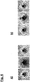
- the recording of these individual spot images assigned to different focal positions would allow the phase of the wavefront to be calculated back if the individual spot images are from each other would be independent (i.e. there would be no mutual influence through interference).
- phase retrieval e.g. Gerchberg-Saxton algorithm
- there are unavoidable interferences between the individual spot images which as in Fig. 6 hinted at a pronounced mutual disturbance (where Figure 6a ideal spot images without taking into account the interference and Figure 6b shows real spot images with consideration of the interference).
- step S410 estimated values for the beam parameters sought are used as a basis (step S410), the corresponding parameter set being designated here by a 1 , a 2 , a 3 ,...
- These parameters for describing the beam can be, for example, beam size, beam decentering in x-direction, beam decentering in y-direction, beam inclination in x-direction, beam inclination in y-direction, beam divergence, astigmatism in x-direction, astigmatism in y- Direction, coma in x direction, coma in y direction and spherical aberration act.
- a Zernike parameterization can also take place here in order to describe and determine corresponding wavefront aberrations, even of a higher order.
- a forward simulation then takes place (step S420) to determine a calculated image.
- the beam amplitude to be determined (in the area of scalar diffraction) in the reference plane (ideally near-field plane) at location z 0 is denoted by u ( x, y
- the amplitude is at the entry of the optical element forming the beam-splitting optical arrangement 110 or 310 at position z 1 u x , y
- z 1 - P ⁇ 1 u x , y
- z 0 IFT xy ⁇ z 1 - z 0 ⁇ FT xy u x , y
- z 1 + T x y u x , y
- z 2 P ⁇ 2 u x , y
- z 1 + IFT xy ⁇ z 2 - z 1 ⁇ FT xy u x , y
- the propagator of the free space propagation is known from the formalism of Fourier optics.
- the amplitude is initially according to u ⁇ f x , f y
- z ⁇ FT xy u x , y
- z ⁇ ⁇ dxdy u x , y
- the amplitude in the plane at z in spatial space can finally be reached by reverse transformation using the inverse Fourier transformation u x , y
- z ⁇ A. dxdy ⁇ z - z ⁇
- the correspondingly calculated image (containing the calculated intensity values I calc ) is subtracted from the recorded measurement image (containing the measured intensity values I meas ), whereupon correspondingly modified model parameters for describing the beam are determined and a new forward simulation is based on (step S460 in Fig. 4 ).
- an optimization is carried out, for example using a Levenberg-Marquardt algorithm. This is done according to Fig. 5 the renewed determination of calculated intensity values I calc by means of forward simulation while obtaining a new calculated image, the difference between the calculated image and the recorded measurement image being determined again. This is carried out iteratively until the difference between the calculated image and the recorded measurement image is sufficiently small (or falls below a predetermined threshold value), whereupon the corresponding parameters for describing the beam are output.
- the magnitude of the amplitude is available from the near-field measurement and does not have to be described and adapted as a model.
- the number of descriptive parameters is possibly considerably reduced and, on the other hand, the quality of the information obtained via the beam to be measured is improved.
- a start is preferably first made with a comparatively small scope of the parameter set, the parameter set then being successively expanded with regard to the simultaneously varied parameters, that is to say an adaptive adaptation of the model is carried out. For example, if there are twenty parameters that are generally sought, only ten dominant parameters can initially be released.
- the respective evaluation method or the algorithm can also be adapted to the highest possible speed in beam analysis.
- the information that has already been collected can be used to determine and correct the slight changes in the beam parameters that then still occur in real time.
- the originally non-linear optimization problem can also be linearly approximated.
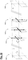
- Fig. 7-11 show schematic representations to explain further embodiments of the invention. What these embodiments have in common is that the beam-splitting optical arrangement according to the invention is designed in such a way that the beam splitting takes place "two-dimensionally" as the rays generated in this splitting relative to one another with a longitudinal focus offset in each case in a plane transverse to the direction of light propagation with regard to the points of impact on the plane form a two-dimensional grid-like arrangement and thus - according to one aspect of this embodiment - are particularly suitable for effectively filling a two-dimensional sensor or detector surface. According to a further aspect of this embodiment, a significant expansion of the measurement range can also be achieved here, as will be described in more detail below.
- two diffractive optical elements 711, 712 can be provided, of which in turn one diffractive element 711, based on the direction of light propagation (running in the z-direction in the drawn coordinate system), is in front of an analogous to the embodiment of FIG Fig. 2a existing refractive optical element (refractive lens) 713 and the other diffractive optical element 712 after this refractive optical element 713 is arranged.
- the diffractive structure required for two-dimensional beam splitting can also be implemented in another suitable manner.
- FIG. 9 The mode of action according to Fig. 7
- the beam-splitting optical arrangement formed by the diffractive optical elements 711, 712 and the refractive optical element 713 is shown in FIG Fig. 9 illustrated (where analog or functionally equivalent components are designated with reference numerals increased by "200").
- the first diffractive optical element 911 splits the incident beam with fanning out into partial beams which diverge in the xz plane
- the second diffractive optical element 911 produces a splitting with fanning out into partial beams which diverge in the yz plane.
- the resulting two-dimensional beam distribution obtained in the sensor or detector plane is designated by “950”.
- FIG. 14 shows, based on the basic structure of the beam-splitting optical arrangement according to FIG Fig. 7 or.
- Fig. 9 a schematic illustration to explain an exemplary geometric design.
- the aforementioned two diffractive optical elements are only indicated here by the respective planes 1011 and 1012, at the same time decentering by offsetting the respective diffractive structure in a plane perpendicular to the optical axis by each to achieve a lateral offset of the partial beams ("symmetry break") a distance "d x " or "d y " is indicated.
- symmetry break a distance "d x " or "d y " is indicated.
- Fig. 7 or 9 formed multifocal optical system has analogous to the embodiment of Fig. 2a several useful focal lengths, with the following approximation if the distance between the diffractive optical elements and the refractive lens is neglected: f m , n ⁇ f 0 f 1 * f 2 * f 1 * n + f 2 * m + f 0 mn
- f 1 * and f 2 * the respective focal lengths of the first and second diffractive optical elements 911, 912 (based on the respective first positive diffraction order) and f 0 denotes the focal length of the refractive optical element 913, while "m” and “n” denote the diffraction orders of the respective diffraction on the first and second diffractive optical element 911, 912, respectively.
- the focal lengths of the first and second diffractive optical elements 911, 912 are selected to be different from one another, with the result that the element with the relatively smaller focal length generates the relatively larger longitudinal focus offset and vice versa.
- the focal length of the first diffractive optical element 911 can be a factor of five greater than the focal length of the second diffractive optical element 912.
- Figure 11a first shows a possible, with a beam-splitting optical arrangement according to the invention according to Fig. 7 or 9 distribution of focal lengths obtained via the individual fanned out beams.
- One value group "A”, “B”, “C”, ... each corresponds to seven (corresponding to the number of diffraction orders in the value range from -3 to +3 selected as an example) values or points in the diagram of a line in the two-dimensional beam distribution obtained in the sensor or detector plane.
- a measurement range expansion compared to that in the exemplary embodiment of FIG Fig.
- the above-described extension of the measuring range can be used to take into account large focus variations of the respective beam to be characterized, such as occur, for example, in applications in material processing, particularly with high laser powers due to heating and deformation of the individual optical components, namely the "capture range" of the respective Focus values significant (according to Figures 11a-c eg by a factor of seven) with the same high resolution.
- this extension of the measuring range can be used to implement an overall ISO-compliant beam characterization insofar as measuring points are each "sufficient" or the number prescribed by the respective ISO standard both in the immediate vicinity of the focus and at a sufficient distance from the focus ( e.g. at a distance of two Raleigh lengths) of the beam.
- the diffractive structure required for two-dimensional beam splitting can also be achieved in another suitable manner.
- the sensor arrangement eg CCD camera
- the sensor arrangement is each designated with "815".
- a single, already “two-dimensional" (ie periodic diffractive structures in mutually different, in particular having perpendicular directions) diffractive optical element 811 or 821 can be used and based on the direction of light propagation in a beam-splitting optical arrangement 810 or . 820 either before ( Figure 8a ) or after ( Figure 8b ) the refractive optical element 813 or 823 are arranged.
- the diffractive structures In a beam-splitting optical arrangement 830, the diffractive structures (again extending in mutually different, in particular perpendicular directions) can also be formed on plano-convex lenses 831, 832.
- a beam-splitting optical arrangement 840 can also have a diffractive optical element 841 with a complex diffractive structure (for example as a complex coded CGH), which causes diffraction in mutually different, in particular perpendicular directions, in combination with a refractive lens 843, this also being the case
- the diffractive optical element 841 can also be arranged after the refractive lens 843 with reference to the direction of light propagation.
- a beam-splitting optical arrangement 850 can also be configured as a refractive lens 851, which has diffractive structures on both its light entry and its light exit surface.
- the diffractive optical elements or diffraction gratings can be implemented as amplitude gratings, phase gratings or hybrid gratings.
Abstract
Die Erfindung betrifft ein Verfahren und eine Vorrichtung zur Strahlanalyse in einem optischen System, wobei eine Mehrzahl von Strahlparametern eines von einer Laserlichtquelle erzeugten und sich entlang einer optischen Achse (OA) ausbreitenden Laserstrahls zur Analyse geometrischer Strahlparameter und Wellenfrontabweichungen ermittelt werden, wobei diese Mehrzahl von Strahlparametern wenigstens einen der Parameter Strahlgröße, Strahldezentrierung, Strahlneigung, Strahldivergenz, Astigmatismus, Koma, sphärische Aberration umfasst, und wobei das Verfahren folgende Schritte aufweist: Aufspalten des Laserstrahls in eine Mehrzahl von Teilstrahlen, welche einen Fokusversatz in bezogen auf die optische Achse (OA) longitudinaler Richtung aufweisen; Aufnehmen eines durch diese Teilstrahlen erzeugten Messbildes, welches unterschiedlichen Fokuslagen entsprechende Spot-Bilder aufweist; Durchführen einer Vorwärtssimulation des Laserstrahls in dem optischen System auf Basis geschätzter Anfangswerte für die Strahlparameter zum Erhalt eines simulierten Bildes; und Berechnen eines Satzes von Werten für die Strahlparameter auf Basis eines Vergleichs zwischen dem simulierten Bild und dem Messbild; Iteratives Durchführen der Schritte der Vorwärtssimulation und des Berechnens eines Satzes von Werten für die Strahlparameter, wobei die jeweils berechneten Werte für die Strahlparameter einer jeweils nachfolgenden Vorwärtssimulation zugrundegelegt werden, und Ausgeben von durch diese Iteration ermittelten Ausgabewerten für die Strahlparameter.The invention relates to a method and a device for beam analysis in an optical system, with a plurality of beam parameters of a laser beam generated by a laser light source and propagating along an optical axis (OA) being determined for the analysis of geometric beam parameters and wavefront deviations, this plurality of beam parameters comprises at least one of the parameters beam size, beam decentering, beam inclination, beam divergence, astigmatism, coma, spherical aberration, and wherein the method comprises the following steps: splitting the laser beam into a plurality of partial beams which have a focus offset in relation to the optical axis (OA) longitudinal Have direction; Recording a measurement image generated by these partial beams which has spot images corresponding to different focus positions; Performing a forward simulation of the laser beam in the optical system on the basis of estimated initial values for the beam parameters to obtain a simulated image; and calculating a set of values for the beam parameters based on a comparison between the simulated image and the measurement image; Iterative implementation of the steps of the forward simulation and the calculation of a set of values for the beam parameters, the respectively calculated values for the beam parameters being used as a basis for a respective subsequent forward simulation, and outputting of output values for the beam parameters determined by this iteration.
Description
Die vorliegende Anmeldung ist eine Teilanmeldung von
Die Erfindung betrifft ein Verfahren und eine Vorrichtung zur Strahlanalyse in einem optischen System. Die Erfindung ist insbesondere einsetzbar, um bei einem Laserstrahl über eine Analyse der geometrischen Strahlparameter (wie Lage und Kipp) hinaus auch Aufschluss über etwaige Wellenfrontabweichungen zu erlangen und diese ggf. in Echtzeit während des Betriebs des jeweiligen optischen Systems zu korrigieren.The invention relates to a method and a device for beam analysis in an optical system. The invention can be used in particular to obtain information about any wavefront deviations in a laser beam via an analysis of the geometric beam parameters (such as position and tilt) and, if necessary, to correct them in real time during the operation of the respective optical system.
Die Erfindung ist zur Analyse elektromagnetischer Strahlung geeignet, wie sie z.B. in Laserplasmaquellen (etwa bei einer EUV-Quelle einer mikrolithographischen Projektionsbelichtungsanlage) eingesetzt wird, jedoch nicht hierauf beschränkt. In weiteren Anwendungen ist die Erfindung auch allgemein dazu geeignet, elektromagnetische Strahlung, die zu beliebigen (insbesondere Mess- oder Diagnose-) Zwecken eingesetzt wird, zu analysieren.The invention is suitable for analyzing electromagnetic radiation such as is used, for example, in laser plasma sources (for example in the case of an EUV source of a microlithographic projection exposure system), but is not restricted to this. In further applications, the invention is also generally suitable for analyzing electromagnetic radiation that is used for any (in particular measurement or diagnostic) purposes.
Viele Laseranwendungen erfordern eine möglichst genaue Kenntnis von Strahlparametern wie z.B. der Strahlgröße, Strahldezentrierung, Strahlneigung oder Strahldivergenz) sowie auch die Korrektur von Aberrationen (wie z.B. Astigmatismus, Koma und sphärische Aberration).Many laser applications require the most accurate possible knowledge of beam parameters such as beam size, beam decentering, beam inclination or beam divergence) as well as the correction of aberrations (such as astigmatism, coma and spherical aberration).
Ein hierbei in der Praxis auftretendes Problem ist, dass z.B. thermisch induzierte Wellenfrontänderungen bzw. Aberrationen der Laserstrahlen auftreten können, deren möglichst exakte Kenntnis für eine im Betrieb (d.h. in Echtzeit) erfolgende Korrektur notwendig ist.A problem that arises in practice is that, for example, thermally induced wavefront changes or aberrations of the laser beams can occur, the exact knowledge of which is necessary for a correction that takes place during operation (i.e. in real time).
Der Einsatz von herkömmlicherweise zur Wellenfrontmessung gebräuchlichen Sensoren (wie z.B. sogenannten Shack-Hartmann-Sensoren mit einer in der Brennebene einer Mikrolinsenanordnung befindlichen CCD-Kamera) ist hier aber insoweit nur beschränkt geeignet, als aufgrund der durch die Messanordnung prinzipbedingt eingeführten geometrischen Bezugszentren (z.B. Scheitel bzw. Aperturen der Linsen in der Mikrolinsenanordnung bei einem Shack-Hartmann-Sensor) das jeweilige Messergebnis auch durch Effekte beeinflusst wird, welche auf der Wechselwirkung bzw. Scherung des Koordinatensystems der Laserstrahlung einerseits mit dem Koordinatensystem der Messanordnung andererseits beruhen (so dass quasi das der Messanordnung eigene intrinsische Koordinatensystem dem Messergebnis "aufgeprägt" wird). Dies hat insbesondere zur Folge, dass bei der Messung auftretende Strahlstörungen etwa infolge einer Positionsänderung der Messanordnung relativ zum Laserstrahl sich unmittelbar im Messergebnis bemerkbar machen und eine zuverlässige Wellenfrontanalyse insoweit erschweren bzw. verhindern, als nicht feststellbar ist, ob ein gemessener Wellenfronteffekt auf einer tatsächlich aufgetretenen (z.B. thermisch induzierten) Wellenfrontmodifikation oder nur einer Positionsänderung (z.B. "Wackeln") der Messanordnung relativ zum Laserstrahl beruht.The use of sensors conventionally used for wavefront measurement (such as so-called Shack-Hartmann sensors with a CCD camera located in the focal plane of a microlens array) is only suitable to a limited extent here, however, as due to the geometrical reference centers (e.g. vertices) introduced by the measuring arrangement or apertures of the lenses in the microlens array in a Shack-Hartmann sensor) the respective measurement result is also influenced by effects that are based on the interaction or shear of the coordinate system of the laser radiation on the one hand with the coordinate system of the measurement arrangement on the other hand (so that the Measurement arrangement own intrinsic coordinate system is "impressed" on the measurement result). In particular, this has the consequence that beam disturbances occurring during the measurement, for example as a result of a change in the position of the measuring arrangement relative to the laser beam, are immediately noticeable in the measurement result and make a reliable wavefront analysis more difficult or impossible to the extent that it cannot be determined whether a measured wavefront effect has actually occurred (eg thermally induced) wavefront modification or just a change in position (eg "wobbling") of the measuring arrangement relative to the laser beam.
Mit anderen Worten besteht bei der Analyse von Wellenfrontaberrationen eines Laserstrahls der Bedarf, diese im Koordinatensystem des Laserstrahls selbst (und nicht in demjenigen der Messanordnung) zu ermitteln.In other words, when analyzing wavefront aberrations of a laser beam, there is a need to determine these in the coordinate system of the laser beam itself (and not in that of the measuring arrangement).
Des Weiteren besteht auch der Bedarf, die entsprechenden Ergebnisse hinreichend schnell im Betrieb des jeweiligen Systems zu erhalten, um etwa unter Verwendung eines adaptiven Spiegels oder dergleichen umgehend etwaige Wellenfrontaberrationen korrigieren zu können.Furthermore, there is also the need to obtain the corresponding results sufficiently quickly during operation of the respective system in order to be able to correct any wavefront aberrations immediately using an adaptive mirror or the like.
Eine lediglich beispielhafte Laseranwendung ist die Laserplasmaquelle, welche z.B. in der Lithographie zur Erzeugung von EUV-Licht (z.B. bei Wellenlängen von z.B. etwa 13 nm oder etwa 7 nm) eingesetzt wird und zu der
Sowohl die Bestimmung der Tröpfchenposition der das Targetmaterial bildenden (z.B. Zinn-) Tröpfchen als auch die Bestimmung der Fokuslage der entsprechend nachzuführenden Laserstrahlen können mit einer sogenannten Strahlpropagationskamera erfolgen, wobei sowohl die Laserstrahlen in "Vorwärtsrichtung" (d.h. die Infrarotstrahlung 6 vor dem Auftreffen auf die jeweiligen Target-Tröpfchen) als auch die Laserstrahlen in "Rückwärtsrichtung" (d.h. die von dem jeweiligen Target-Tröpfchen zurückreflektierte Infrarotstrahlung 6) erfasst und die für die Laserstrahlsowie Tröpfchenführung benötigten Messdaten gewonnen werden. Hierbei besteht der Bedarf, thermisch induzierte Aberrationen umgehend korrigiert zu können, was eine genaue und schnelle Analyse der Laserstrahlen erfordert.Both the determination of the droplet position of the (e.g. tin) droplets forming the target material and the determination of the focus position of the laser beams to be tracked can be done with a so-called beam propagation camera, both the laser beams in the "forward direction" (ie the
Zum Stand der Technik wird beispielhaft auf
Aufgabe der vorliegenden Erfindung ist es, ein Verfahren und eine Vorrichtung zur Strahlanalyse bereitzustellen, welche eine zuverlässige bzw. möglichst störungsfreie sowie hinreichend schnell erfolgende Analyse ermöglichen.The object of the present invention is to provide a method and a device for beam analysis which enable a reliable or as trouble-free as possible and sufficiently rapid analysis.
Diese Aufgabe wird durch das Verfahren gemäß den Merkmalen des unabhängigen Patentanspruchs 1 sowie die Vorrichtung gemäß den Merkmalen des nebengeordneten Patentanspruchs 13 gelöst.This object is achieved by the method according to the features of
Ein erfindungsgemäßes Verfahren zur Strahlanalyse gemäß Anspruch 1 weist folgende Schritte auf:
- Aufspalten des Laserstrahls in eine Mehrzahl von Teilstrahlen, welche einen Fokusversatz in bezogen auf die optische Achse longitudinaler Richtung aufweisen,
- Aufnehmen eines durch diese Teilstrahlen erzeugten Messbildes, welches unterschiedlichen Fokuslagen entsprechende Spot-Bilder aufweist;
- Durchführen einer Vorwärtssimulation des Laserstrahls in dem optischen System auf Basis geschätzter Anfangswerte für die Strahlparameter zum Erhalt eines simulierten Bildes, und
- Berechnen eines Satzes von Werten für die Strahlparameter auf Basis eines Vergleichs zwischen dem simulierten Bild und dem Messbild.
- Splitting the laser beam into a plurality of partial beams which have a focus offset in the longitudinal direction in relation to the optical axis,
- Recording of a measurement image generated by these partial beams, which has spot images corresponding to different focus positions;
- Carrying out a forward simulation of the laser beam in the optical system on the basis of estimated initial values for the beam parameters to obtain a simulated image, and
- Calculating a set of values for the beam parameters based on a comparison between the simulated image and the measurement image.
Unter der "Aufspaltung eines Strahls in eine Mehrzahl von Teilstrahlen" ist im Rahmen der vorliegenden Anmeldung zu verstehen, dass diese Teilstrahlen jeweils eine Kopie des ursprünglichen aufgespaltenen Strahls insofern darstellen, als die Teilstrahlen jeweils die gleichen geometrischen Parameter wie der ursprüngliche Strahl aufweisen, wobei lediglich die Intensität der Teilstrahlen gegenüber der Intensität des ursprünglichen Strahls infolge der Aufspaltung in mehrere Teilstrahlen entsprechend reduziert ist. Im Ergebnis wird mit der strahlaufspaltenden optischen Anordnung der zu analysierende Strahl in geeigneter Weise in eine Mehrzahl von Teilstrahlen repliziert, wobei mit einer Sensoranordnung geeigneter Ausdehnung mehrere Strahlschnitte bzw. Messspots gleichzeitig aufgezeichnet werden können.The "splitting of a beam into a plurality of partial beams" is to be understood in the context of the present application that these partial beams each represent a copy of the original split beam insofar as the partial beams each have the same geometric parameters as the original beam, with only the intensity of the partial beams is correspondingly reduced compared to the intensity of the original beam due to the splitting into several partial beams. As a result, with the beam-splitting optical arrangement, the beam to be analyzed is replicated in a suitable manner into a plurality of partial beams, with several beam sections or measurement spots being able to be recorded at the same time with a sensor arrangement of suitable expansion.
Gemäß der Erfindung weist das Verfahren weiter die Schritte auf:
- Iteratives Durchführen der Schritte der Vorwärtssimulation und des Berechnens eines Satzes von Werten für die Strahlparameter, wobei die jeweils berechneten Werte für die Strahlparameter einer jeweils nachfolgenden Vorwärtssimulation zugrundegelegt werden, und
- Ausgeben von durch diese Iteration ermittelten Ausgabewerten für die Strahlparameter.
- Iterative implementation of the steps of forward simulation and of calculating a set of values for the beam parameters, the respectively calculated values for the beam parameters being used as a basis for a respective subsequent forward simulation, and
- Output of output values for the beam parameters determined by this iteration.
Gemäß einer Ausführungsform der Erfindung erfolgt somit das Berechnen eines Satzes von Werten für die Strahlparameter insbesondere iterativ auf Basis einer Mehrzahl von Vergleichen zwischen aufgenommenen Messbildern und berechneten bzw. simulierten Bildern. Hierdurch wird dem Umstand Rechnung getragen, dass unvermeidliche Interferenzen zwischen den einzelnen, unterschiedlichen Fokuslagen zugeordneten Messbildern ("Spot-Bilder") auftreten, wobei die Interferenzen insbesondere zu vergleichsweise großen gegenseitigen Störungen der Spots führen können. Die einzelnen, unterschiedlichen Fokuslagen zugeordneten Messbilder können aufgrund der gegenseitigen Störungen nicht einfach als unabhängig voneinander angesehen werden, was wiederum einer "separaten" Vorwärts- und Rückwärtspropagation - bei welcher z.B. die den einzelnen Fokuslagen zugeordneten Komponenten der strahlaufspaltenden optischen Anordnung als entkoppelt betrachtet bzw. einzeln berücksichtigt werden - durch das optische System hindurch entgegensteht bzw. ein korrektes Zurückrechnen auf die Strahlparameter verhindert.According to one embodiment of the invention, a set of values for the beam parameters is calculated in particular iteratively on the basis of a plurality of comparisons between recorded measurement images and calculated or simulated images. This takes account of the fact that unavoidable interference occurs between the individual measurement images (“spot images”) assigned to different focal positions, the interference in particular leading to comparatively large mutual interference between the spots. The individual measurement images assigned to different focal positions cannot simply be viewed as independent of one another due to the mutual interference, which in turn results in "separate" forward and backward propagation - in which, for example, the components of the beam-splitting optical arrangement assigned to the individual focal positions as considered decoupled or taken into account individually - counteracts through the optical system or prevents correct calculation of the beam parameters.
Gemäß einer Ausführungsform umfasst das Verfahren ferner den Schritt der Aufnahme eines durch den Strahl erzeugten Nahfeldbildes.According to one embodiment, the method further comprises the step of recording a near-field image generated by the beam.
Die Aufnahme des Nahfeldbildes und die Aufnahme eines dem durch die Teilstrahlen erzeugten Messbild entsprechenden Fernfeldbildes können simultan erfolgen. Ferner können zur Aufnahme der Messbilder auch mehr als eine Sensoranordnung (z.B. eine Sensoranordnung zur Aufnahme des Nahfeldbildes und eine weitere Sensoranordnung zur Aufnahme des Fernfeldbildes) verwendet werden.The recording of the near-field image and the recording of a far-field image corresponding to the measurement image generated by the partial beams can take place simultaneously. Furthermore, more than one sensor arrangement (e.g. one sensor arrangement for recording the near-field image and another sensor arrangement for recording the far-field image) can also be used to record the measurement images.
Unter "Nahfeld" wird hierbei die Amplituden- bzw. Intensitätsverteilung in einer Schnittebene senkrecht zur Ausbreitungsrichtung im Bereich des kollimierten (d.h. aufgeweiteten bzw. nahezu divergenzfreien) Strahls bezeichnet. Das "Fernfeld" hingegen entspricht der Amplituden- bzw. Intensitätsverteilung in einer taillen- bzw. fokusnahen Ebene senkrecht zur Strahlausbreitung im Bereich des fokussierten bzw. konvergenten Strahls.The term "near field" refers to the amplitude or intensity distribution in a section plane perpendicular to the direction of propagation in the area of the collimated (i.e. expanded or almost divergence-free) beam. The “far field”, on the other hand, corresponds to the amplitude or intensity distribution in a plane near the waist or focus, perpendicular to the beam propagation in the area of the focused or convergent beam.
Diese Aufzeichnung des Nahfeldbildes ermöglicht es, den Betragsanteil der komplexen Amplitudenfunktion (als Quadratwurzel der Intensität) für den zu analysierenden Strahl unmittelbar im Nahfeld direkt zu bestimmen. Dies ist insoweit besonders vorteilhaft, als der Betrag der Amplitude aus dem Fernfeldbild (d.h. dem fokusnahen Bild nach Durchlaufen der strahlformenden und strahlaufspaltenden Optik) nur schwierig zu bestimmen ist, da die Fokussiereigenschaften bzw. Fernfeldbilder im Wesentlichen durch die Phase der elektromagnetischen Strahlung dominiert sind und der Betrag der Amplitude im Fernfeld nur schlecht zugänglich ist. Durch die Erfindung wird somit explizit dem Umstand Rechnung getragen, dass Nahfeld und Fernfeld insofern gewissermaßen komplementäre Information tragen, als sie unterschiedliche Aspekte der komplexen Amplitudenfunktion abbilden. Das erfindungsgemäße Konzept hat zur Folge, dass aus dem Fernfeldbild i.W. nur noch die Wellenfront bzw. die Phase der komplexen Amplitude bestimmt werden muss. Im Ergebnis wird daher das Rekonstruktionsergebnis bei der erfindungsgemäßen zusätzlichen Berücksichtigung der Nahfeldinformation im Vergleich zu einer alleinigen Berücksichtigung der Fernfeldinformation deutlich verbessert.This recording of the near-field image makes it possible to determine the absolute value of the complex amplitude function (as the square root of the intensity) for the beam to be analyzed directly in the near-field. This is particularly advantageous as the magnitude of the amplitude is difficult to determine from the far-field image (i.e. the image near the focus after passing through the beam-shaping and beam-splitting optics), since the focusing properties or far-field images are essentially dominated by the phase of the electromagnetic radiation and the magnitude of the amplitude in the far field is difficult to access. The invention thus explicitly takes into account the fact that the near field and far field carry complementary information to a certain extent in that they map different aspects of the complex amplitude function. The inventive concept has the consequence that from the far field image In general only the wave front or the phase of the complex amplitude has to be determined. As a result, the reconstruction result with the additional consideration of the near-field information according to the invention is therefore significantly improved in comparison to a sole consideration of the far-field information.
Der Umstand, dass erfindungsgemäß bereits eine einzige mit einer Sensoranordnung erfolgte Aufnahme (d.h. die simultane Aufnahme eines Nahfeldbildes und eines Fernfeldbildes) die vollständige, zur Strahlauswertung erforderliche Information liefert, hat den weiteren Vorteil, dass z.B. bei einem gepulsten Laser, oder auch bei anderen Lasertypen (wie z.B. CW-Lasern) mit ausgeprägten Fluktuationen in den Strahleigenschaften, einzelne (z.B. pulsaufgelöste) Wellenfrontanalysen (gewissermaßen als "single shot"-Messungen) durchgeführt werden können.The fact that according to the invention already a single recording made with a sensor arrangement (ie the simultaneous recording of a near-field image and a far-field image) provides the complete information required for beam evaluation has the further advantage that, for example, with a pulsed laser or with other laser types (such as CW lasers) with pronounced fluctuations in the beam properties, individual (e.g. pulse-resolved) wavefront analyzes (as it were as "single shot" measurements) can be carried out.
Gemäß der Erfindung umfasst die Mehrzahl von Strahlparametern wenigstens einen der Parameter Strahlgröße, Strahldezentrierung, Strahlneigung, Strahldivergenz, Astigmatismus, Koma, sphärische Aberration, sowie ggf. auch weitere Parameter. Die Aberrationen können beliebiger Ordnung sein und beispielsweise in einem hierarchischen, idealerweise der Symmetrie angepassten Funktionensystem (z.B. Zernike-Polynome) beschrieben werden.According to the invention, the plurality of beam parameters includes at least one of the parameters beam size, beam decentering, beam inclination, beam divergence, astigmatism, coma, spherical aberration, and possibly also further parameters. The aberrations can be of any order and can be described, for example, in a hierarchical system of functions (e.g. Zernike polynomials) that is ideally adapted to symmetry.
Gemäß einer Ausführungsform erfolgt auf Basis der Ausgabewerte für die Strahlparameter eine Manipulation des Strahls unter Anpassung wenigstens eines der Strahlparameter.According to one embodiment, the beam is manipulated on the basis of the output values for the beam parameters while at least one of the beam parameters is adapted.
Gemäß einer Ausführungsform erfolgt das Ausgeben der Ausgabewerte und die Anpassung wenigstens eines der Strahlparameter in Echtzeit während des Betriebs des optischen Systems.According to one embodiment, the output values are output and at least one of the beam parameters is adapted in real time during the operation of the optical system.
Gemäß einer Ausführungsform wird im Laufe der iterativen Durchführung der Schritte der Vorwärtssimulation und des Berechnens eines Satzes von Werten für die Strahlparameter die Anzahl der variierten Strahlparameter variiert, insbesondere reduziert.According to one embodiment, the number of the varied beam parameters is varied, in particular reduced, in the course of the iterative execution of the steps of the forward simulation and the calculation of a set of values for the beam parameters.
Die Erfindung beinhaltet hier das weitere Konzept, unter Nutzung des jeweils zuvor ermittelten Bildes im Sinne eines adaptiven Vorgehens den Modellumfang anzupassen.The invention here includes the further concept of adapting the scope of the model using the previously determined image in the sense of an adaptive procedure.
Hierdurch kann dem Umstand Rechnung getragen werden, dass eine Freigabe einer hohen Anzahl von Parametern bei der iterativen Durchführung der Schritte der Vorwärtssimulation und des Berechnens eines Satzes von Werten für die Strahlparameter zu einer hohen numerischen Komplexität führt, was ggf. einer Echtzeitbestimmung und -anpassung der Strahlparameter (z.B. der Strahlanpassung in einer Laserplasmaquelle) entgegensteht. Vorzugsweise kann z.B. zunächst ein Start mit einem vergleichsweise kleinen Umfang des Parametersatzes erfolgen, wobei dann im weiteren Verlauf der Iteration der Parametersatz hinsichtlich der simultan variierten Parameter sukzessive erweitert (also eine adaptive Anpassung des Modells vorgenommen) wird.This makes it possible to take account of the fact that releasing a large number of parameters when iteratively performing the steps of the forward simulation and calculating a set of values for the beam parameters leads to a high numerical complexity, which may result in real-time determination and adaptation of the Beam parameters (e.g. beam adjustment in a laser plasma source). For example, a start with a comparatively small scope of the parameter set can preferably take place first, with the parameter set then being successively expanded with regard to the simultaneously varied parameters (i.e. an adaptive adaptation of the model is carried out) as the iteration continues.
Gemäß einer Ausführungsform wird im Laufe der iterativen Durchführung der Schritte der Vorwärtssimulation und des Berechnens eines Satzes von Werten für die Strahlparameter ein bei dieser Iteration angewendeter Algorithmus variiert.According to one embodiment, an algorithm used in this iteration is varied in the course of the iterative implementation of the steps of the forward simulation and the calculation of a set of values for the beam parameters.
Beispielsweise kann nach Erreichen eines quasi-stationären Betriebs des jeweiligen Systems (z.B. der Plasmalichtquelle), während dem nur noch geringe Änderungen der Strahlparameter auftreten, eine raschere Auswertemethode gewählt werden, um eine möglichst hohe Geschwindigkeit bei der Strahlanalyse zu erzielen. Dabei kann insbesondere die bereits zuvor gesammelte Information genutzt werden, um in Echtzeit die dann noch auftretenden geringen Änderungen der Strahlparameter bestimmen und korrigieren zu können.For example, after a quasi-stationary operation of the respective system (e.g. the plasma light source), during which only minor changes in the beam parameters occur, a more rapid evaluation method can be selected in order to achieve the highest possible speed in the beam analysis. In particular, the information that has already been collected can be used to determine and correct the slight changes in the beam parameters that still occur in real time.
Im Ergebnis kann so erreicht werden, dass etwa in einer Plasmalichtquelle der Laserstrahl hinsichtlich der Strahlparameter zugleich genau und schnell geführt werden kann, da z.B. thermisch induzierte Aberrationen umgehend korrigiert werden können.As a result, it can be achieved that, for example, in a plasma light source, the laser beam can be guided precisely and quickly with regard to the beam parameters, since, for example, thermally induced aberrations can be corrected immediately.
Gemäß einer Ausführungsform erfolgt die Strahlaufspaltung unter Verwendung einer strahlaufspaltenden optischen Anordnung, welche sphärische Wellenfrontdeformationen des Strahls bewirkt. Der Erfindung liegt hier das weitere Konzept zugrunde, eine Wellenfrontbestimmung auf Basis einer durch sphärische Wellenfrontdeformationen des Strahls erzielten Aufspaltung in mehrere Teilstrahlen, denen unterschiedliche Fokuslagen zugeordnet sind, zu realisieren.According to one embodiment, the beam splitting takes place using a beam-splitting optical arrangement which causes spherical wavefront deformations of the beam. The invention is based here on the further concept of realizing a wavefront determination on the basis of a splitting achieved by spherical wavefront deformations of the beam into several partial beams to which different focal positions are assigned.
Dadurch, dass zur Strahlaufspaltung ausschließlich sphärische Wellenfrontdeformationen des Strahls durchgeführt werden, wird die Aufprägung eines zusätzlichen Koordinatensystems aufgrund der Messanordnung und damit eine unerwünschte Wechselwirkung bzw. Scherung eines solchen Koordinatensystems mit dem Koordinatensystem der Laserstrahlung vermieden. Hierbei geht die Erfindung von der Überlegung aus, dass eine sphärische Wellenfront aufgrund der an jedem Ort konstanten Krümmung kein Zentrum oder einen in irgendeiner Weise ausgezeichneten Ort besitzt, so dass durch eine in solcher Weise aufgebaute Messanordnung auch kein spezielles Koordinatensystem erzeugt, welches dem Koordinatensystem der Laserstrahlung aufgeprägt werden kann. Grundsätzlich kann ein ausschließlich sphärische Wellenfrontdeformationen des Strahls hervorrufendes optisches System aus Linsen, aber auch z.B. durch ein diffraktives optisches Element, aufgebaut werden.Because only spherical wavefront deformations of the beam are carried out to split the beam, the imprinting of an additional coordinate system due to the measuring arrangement and thus an undesired interaction or shear of such a coordinate system with the coordinate system of the laser radiation is avoided. The invention is based on the idea that a spherical wavefront has no center or any particular location due to the constant curvature at every location, so that a measuring arrangement constructed in this way does not generate a special coordinate system that corresponds to the coordinate system of Laser radiation can be impressed. In principle, an optical system that causes exclusively spherical wavefront deformations of the beam can be built up from lenses, but also e.g. from a diffractive optical element.
Gemäß einer Ausführungsform weist die strahlaufspaltende optische Anordnung wenigstens eine diffraktive Struktur auf.According to one embodiment, the beam-splitting optical arrangement has at least one diffractive structure.
Die Erfindung beinhaltet hier weiter das Konzept, durch Verwendung einer diffraktiven Struktur die von einer solchen diffraktiven Struktur erzeugte Mehrzahl von Fokuslagen, die den unterschiedlichen Beugungsordnungen der diffraktiven Struktur entsprechen, zur Realisierung des longitudinalen Fokusversatzes zu erzielen. Mit anderen Worten macht sich die Erfindung die üblicherweise unerwünschte Eigenschaft einer diffraktiven Linse, entsprechend den unterschiedlichen Beugungsordnungen voneinander verschiedene Fokuslagen zu erzeugen, gezielt zunutze, um einen zur Strahlanalyse erforderlichen longitudinalen Fokusversatz zu realisieren. Zugleich macht sich die Erfindung den weiteren Umstand zunutze, dass ein über den vorstehend genannten longitudinalen Fokusversatz hinaus zur Ermöglichung einer simultanen Aufzeichnung am Ort der Sensoranordnung notwendiger lateraler Versatz der Teilstrahlen vergleichsweise einfach über einen "Symmetriebruch" erreichbar ist, welcher z.B. durch eine einfache Dezentrierung der diffraktiven Struktur (entweder durch Versetzung in einer zur optischen Achse senkrechten Ebene oder bereits durch entsprechendes Design der diffraktiven Struktur) erzielt werden kann.The invention here further includes the concept of using a diffractive structure to achieve the plurality of focus positions generated by such a diffractive structure, which correspond to the different diffraction orders of the diffractive structure, for realizing the longitudinal focus offset. In other words, the invention makes targeted use of the usually undesirable property of a diffractive lens of generating different focal positions corresponding to the different diffraction orders, in order to achieve a longitudinal focus offset required for beam analysis realize. At the same time, the invention makes use of the further fact that a lateral offset of the partial beams that is necessary beyond the aforementioned longitudinal focus offset to enable simultaneous recording at the location of the sensor arrangement can be achieved comparatively easily via a "symmetry break", which can be achieved, for example, by simply decentering the diffractive structure (either by offset in a plane perpendicular to the optical axis or already by appropriate design of the diffractive structure) can be achieved.
Gemäß einer Ausführungsform ist die strahlaufspaltende optische Anordnung derart ausgelegt, dass sie einen auf die Anordnung auftreffenden Strahl in Teilstrahlen aufspaltet, wobei die Auftreffpunkte dieser Teilstrahlen auf eine quer zur Lichtausbreitungsrichtung des Strahls verlaufende Ebene eine zweidimensionale, gitterartige Verteilung bilden (wobei es sich bei dieser Ebene insbesondere um die Detektorebene, in welcher das Luftbild erzeugt wird, handeln kann). Dabei können die Auftreffpunkte als geometrisches Zentrum der jeweiligen Schwerstrahlen oder als in anderer geeigneter Weise ausgezeichnete Punkte der jeweiligen Teilstrahlen definiert sein. Des Weiteren sollen von dem Begriff "zweidimensionale, gitterartige Verteilung" auch nicht regelmäßige bzw. nicht periodische zweidimensionale Verteilungen umfasst sein.According to one embodiment, the beam-splitting optical arrangement is designed in such a way that it splits a beam impinging on the arrangement into partial beams, the points of incidence of these partial beams forming a two-dimensional, lattice-like distribution on a plane running transversely to the direction of light propagation of the beam in particular the detector plane in which the aerial image is generated). The points of impact can be defined as the geometrical center of the respective heavy jets or as points of the respective partial jets which are distinguished in another suitable manner. Furthermore, the term “two-dimensional, grid-like distribution” should also include non-regular or non-periodic two-dimensional distributions.
Gemäß einer Ausführungsform weist die strahlaufspaltende optische Anordnung wenigstens zwei diffraktive Strukturen auf, welche sich in voneinander verschiedenen, insbesondere zueinander senkrechten Richtungen erstrecken.According to one embodiment, the beam-splitting optical arrangement has at least two diffractive structures which extend in directions that are different from one another, in particular mutually perpendicular directions.
Eine solche Ausgestaltung der erfindungsgemäßen strahlaufspaltenden optischen Anordnung erweist sich in mehrfacher Hinsicht als vorteilhaft, wobei in diesem Zusammenhang zunächst auf die effizientere Ausfüllung einer (typischerweise sich in zwei Ebenen erstreckenden) Sensor- bzw. Detektorebene hinzuweisen ist. Darüber hinaus kann jedoch - wie im Weiteren noch detaillierter erläutert - bei geeigneter Auslegung der strahlaufspaltenden optischen Anordnung bzw. der darin vorgesehenen diffraktiven Strukturen eine signifikante Messbereichserweiterung bei unverändert hoher Auflösung erzielt werden. Diese Messbereichserweiterung kann ihrerseits wiederum zum einen dazu dienen, den "Fangbereich" hinsichtlich erfassbarer Fokuswerte des zu analysierenden Strahls bei unverändert hoher Auflösung (nämlich unter Bereitstellung einer ausreichenden Anzahl von Messpunkten in dem betreffenden Fokusbereich) zu vergrößern. Auf diese Weise kann den vergleichsweise großen Fokusvariationen des zu charakterisierenden Strahls, wie sie beispielsweise in Anwendungen der Materialbearbeitung oder auch in der eingangs beschriebenen Laserplasmaquelle bei hohen Laserleistungen infolge Erwärmung und Deformation der einzelnen optischen Komponenten auftreten, Rechnung getragen werden. Dabei kann gegebenenfalls auch eine ISO-konforme Strahlcharakterisierung insofern realisiert werden, als Messpunkte in jeweils hinreichender Anzahl sowohl in unmittelbarer Nähe des Fokus des zu analysierenden Strahls als auch in hinreichender Entfernung von diesem Fokus erhalten werden. Zum anderen kann bei Bedarf innerhalb des jeweils abgedeckten Messbereichs - wie ebenfalls noch näher erläutert - eine Redundanz hinsichtlich der bereitgestellten Messpunkte bzw. Fokuswerte erzielt werden, welche wiederum zur Kalibrierung des Messsystems genutzt werden kann.Such a configuration of the beam-splitting optical arrangement according to the invention proves to be advantageous in several respects, whereby in this context reference should first be made to the more efficient filling of a sensor or detector plane (typically extending in two planes). In addition, however, as explained in more detail below, with a suitable design of the beam-splitting optical arrangement or the diffractive structures provided therein, a significant expansion of the measurement range can be achieved with unchanged high resolution. These The measuring range extension can in turn serve to enlarge the "capture range" with regard to detectable focus values of the beam to be analyzed while maintaining the same high resolution (namely by providing a sufficient number of measuring points in the relevant focus area). In this way, the comparatively large focus variations of the beam to be characterized, such as occur, for example, in applications in material processing or in the laser plasma source described above at high laser powers as a result of heating and deformation of the individual optical components, can be taken into account. If necessary, an ISO-compliant beam characterization can also be implemented to the extent that a sufficient number of measurement points are obtained both in the immediate vicinity of the focus of the beam to be analyzed and at a sufficient distance from this focus. On the other hand, if necessary - as will also be explained in more detail - a redundancy can be achieved with regard to the provided measuring points or focus values within the respective covered measuring range, which in turn can be used to calibrate the measuring system.
Gemäß einer Ausführungsform unterscheiden sich diese diffraktiven Strukturen in ihrer auf die jeweils erste positive Beugungsordnung bezogenen Brennweite um wenigstens einen Faktor 3, insbesondere um wenigstens einen Faktor 4, weiter insbesondere um wenigstens einen Faktor 5.According to one embodiment, these diffractive structures differ in their focal length related to the respective first positive order of diffraction by at least a factor of 3, in particular by at least a factor 4, further in particular by at least a factor 5.
Gemäß einer Ausführungsform ist das optische System eine Laserplasmaquelle.According to one embodiment, the optical system is a laser plasma source.
Die Erfindung ist jedoch nicht hierauf beschränkt, sondern in vielen anderen Bereichen anwendbar. Eine Anwendung kann beispielsweise in der Lasermesstechnik erfolgen (z.B. überall dort, wo herkömmlicherweise Shack-Hartmann-Sensoren eingesetzt werden). Weitere vorteilhafte Anwendungen der Erfindung betreffen die Medizintechnik, die Materialbearbeitung und die Kommunikationstechnik.However, the invention is not restricted to this but can be used in many other areas. It can be used, for example, in laser measurement technology (eg wherever Shack-Hartmann sensors are conventionally used). Further advantageous applications of the invention relate to medical technology, material processing and communication technology.
Die Erfindung betrifft weiter eine Vorrichtung zur Strahlanalyse in einem optischen System, mit wenigstens einer strahlaufspaltenden optischen Anordnung, welche eine Strahlaufspaltung eines im Betrieb auf die strahlaufspaltende optische Anordnung entlang der optischen Achse auftreffenden Strahls in eine Mehrzahl von Teilstrahlen bewirkt, welche einen Fokusversatz in bezogen auf die optische Achse longitudinaler Richtung aufweisen, und wenigstens einer Sensoranordnung zur Erfassung dieser Teilstrahlen, wobei die Vorrichtung zur Durchführung eines Verfahrens mit den vorstehend beschriebenen Merkmalen ausgestaltet ist.The invention further relates to a device for beam analysis in an optical system, with at least one beam-splitting optical arrangement, which causes a beam splitting of a beam impinging on the beam-splitting optical arrangement along the optical axis during operation into a plurality of partial beams which have a focus offset in relation to have the optical axis in the longitudinal direction, and at least one sensor arrangement for detecting these partial beams, the device for carrying out a method being designed with the features described above.
Die Erfindung betrifft weiter auch eine strahlaufspaltende optische Anordnung, wobei die Anordnung eine Strahlaufspaltung eines im Betrieb auf die strahlaufspaltende optische Anordnung entlang der optischen Achse auftreffenden Strahls in eine Mehrzahl von Teilstrahlen bewirkt, welche einen Fokusversatz in bezogen auf die optische Achse longitudinaler Richtung aufweisen, wobei die Auftreffpunkte dieser Teilstrahlen auf eine quer zur Lichtausbreitungsrichtung des Strahls verlaufende Ebene eine zweidimensionale, gitterartige Verteilung bilden, wobei die Anordnung zur Verwendung in einem Verfahren mit den vorstehend beschriebenen Merkmalen ausgestaltet istThe invention also relates to a beam-splitting optical arrangement, the arrangement causing a beam splitting of a beam that strikes the beam-splitting optical arrangement along the optical axis during operation into a plurality of partial beams which have a focus offset in the longitudinal direction with respect to the optical axis, wherein the points of incidence of these partial beams on a plane running transversely to the direction of light propagation of the beam form a two-dimensional, grid-like distribution, the arrangement being designed for use in a method having the features described above
Zu Vorteilen sowie bevorzugten Ausgestaltungen der Vorrichtung bzw. Anordnung wird auf die vorstehenden Ausführungen im Zusammenhang mit dem erfindungsgemäßen Verfahren Bezug genommen.For advantages and preferred configurations of the device or arrangement, reference is made to the above statements in connection with the method according to the invention.
Weitere Ausgestaltungen der Erfindung sind der Beschreibung sowie den Unteransprüchen zu entnehmen.Further refinements of the invention can be found in the description and in the subclaims.
Die Erfindung wird nachstehend anhand von in den beigefügten Abbildungen dargestellten Ausführungsbeispielen näher erläutert.The invention is explained in more detail below with reference to the exemplary embodiments shown in the accompanying figures.
Es zeigen:
Figur 1- eine schematische Darstellung einer in einem erfindungsgemäßen Verfahren beispielhaft verwendeten Messanordnung;
- Figur 2a-2b
- eine schematische Darstellung (
Figur 2a ) bzw. ein Diagramm (Figur 2b ) zur Erläuterung von Aufbau und Wirkungsweise einer beispielhaften Ausführungsform einer strahlaufspaltenden optischen Anordnung; Figur 3- eine schematische Darstellung einer in einem erfindungsgemäßen Verfahren beispielhaft verwendeten Messanordnung in einer weiteren Ausführungsform;
- Figur 4-5
- schematische Darstellungen zur Erläuterung des möglichen Ablaufs eines erfindungsgemäßen Verfahrens;
Figur 6- schematische Darstellungen zur Erläuterung eines der Erfindung zugrundeliegenden Problems;
- Figur 7-11
- schematische Darstellungen zur Erläuterung weiterer Ausführungsformen der Erfindung; und
- Figur 12
- eine schematische Darstellung des Aufbaus einer EUV-Lichtquelle gemäß dem Stand der Technik.
- Figure 1
- a schematic representation of a measuring arrangement used by way of example in a method according to the invention;
- Figures 2a-2b
- a schematic representation (
Figure 2a ) or a diagram (Figure 2b ) to explain the structure and mode of operation of an exemplary embodiment of a beam-splitting optical arrangement; - Figure 3
- a schematic representation of a measuring arrangement used by way of example in a method according to the invention in a further embodiment;
- Figure 4-5
- schematic representations to explain the possible sequence of a method according to the invention;
- Figure 6
- schematic representations to explain a problem on which the invention is based;
- Figure 7-11
- schematic representations to explain further embodiments of the invention; and
- Figure 12
- a schematic representation of the structure of an EUV light source according to the prior art.
Gemäß
Die strahlaufspaltende optische Anordnung 110 weist im Ausführungsbeispiel wie in ![]()
![]()
Darin bezeichnet f 1 die Brennweite der ersten positiven Beugungsordnung und k den Strahlindex bzw. die Beugungsordnung. Die Intensität des jeweiligen Fokus hängt dabei unmittelbar von der Ausführungs- und Approximationsform des zugrundeliegenden (näherungsweise parabolischen Phasenprofils) ab. In Kombination mit einer refraktiven Linse der Brennweite f 0 ergibt sich ein multifokales optisches System mit mehreren Nutzbrennweiten fk , k = 0,±1, ...,k max, wobei bei Vernachlässigung des Abstandes zwischen der diffraktiven Struktur und der refraktiven Linse näherungsweise gilt 
Dieser Zusammenhang ist in
Die Erfindung ist nicht auf die Ausgestaltung der strahlaufspaltenden optischen Anordnung 110 mit einer solchen diffraktiven Struktur beschränkt. Vielmehr kommt es bei der Ausgestaltung der strahlaufspaltenden optischen Anordnung darauf an, dass diese nach Möglichkeit sphärische Wellenfrontdeformationen des auf die strahlaufspaltende optische Anordnung auftreffenden Strahls bewirkt. In weiteren Ausführungsformen kann auch eine andere, hierzu geeignete strahlaufspaltende optische Anordnung, z.B. in Form eines Etalons, verwendet werden.The invention is not limited to the configuration of the beam-splitting
Die von der strahlaufspaltenden optischen Anordnung ausgehenden Teilstrahlen treffen - unter erneutem Bezug auf
Grundsätzlich würde es die Aufnahme dieser einzelnen, jeweils unterschiedlichen Fokuslagen zugeordneten Spot-Bilder durch Anwendung bekannter, sogenannter "Phase Retrieval"-Verfahren (z.B. Gerchberg-Saxton-Algorithmus) erlauben, auf die Phase der Wellenfront zurückzurechnen, wenn die einzelnen Spot-Bilder voneinander unabhängig wären (also keine gegenseitige Beeinflussung durch Interferenz vorliegen würde). Vorliegend sind jedoch unvermeidliche Interferenzen zwischen den einzelnen Spot-Bildern vorhandenen, welche wie in
Mathematisch bedeutet dieser Umstand, dass keine eindeutige Rücktransformation zur unmittelbaren Berechnung der Strahlparameter möglich ist. Um diesem Problem Rechnung zu tragen, werden gemäß der Erfindung in einem modellbasierten Ansatz iterativ Vergleiche zwischen jeweils berechneten bzw. simulierten Bildern und dem aufgenommenen Messbild durchgeführt, wie im Folgenden unter Bezug auf
Wie in dem schematischen Diagramm von
As in the schematic diagram of
Bei diesen Parametern zur Beschreibung des Strahls kann es sich beispielsweise um Strahlgröße, Strahldezentrierung in x-Richtung, Strahldezentrierung in y-Richtung, Strahlneigung in x-Richtung, Strahlneigung in y-Richtung, Strahldivergenz, Astigmatismus in x-Richtung, Astigmatismus in y-Richtung, Koma in x-Richtung, Koma in y-Richtung und sphärische Aberration handeln. Hierbei kann ggf. auch eine Zernike-Parametrisierung erfolgen, um entsprechende Wellenfrontaberrationen auch höherer Ordnung zu beschreiben und zu ermitteln.These parameters for describing the beam can be, for example, beam size, beam decentering in x-direction, beam decentering in y-direction, beam inclination in x-direction, beam inclination in y-direction, beam divergence, astigmatism in x-direction, astigmatism in y- Direction, coma in x direction, coma in y direction and spherical aberration act. If necessary, a Zernike parameterization can also take place here in order to describe and determine corresponding wavefront aberrations, even of a higher order.
Sodann erfolgt eine Vorwärtssimulation (Schritt S420) zur Ermittlung eines berechneten Bildes. Diese Vorwärtssimulation umfasst gemäß ![]()
![]()
Geht man von einer Strahlausbreitung in die positive z-Richtung aus, so ist die zu bestimmende Strahlamplitude (im Bereich der skalaren Beugung) in der Referenzebene (idealerweise Nahfeldebene) am Ort z 0 durch u(x, y|z 0) bezeichnet. Nach Durchlaufen der Freiraumstrecke zwischen der Referenzebene und der Ebene des wirksamen optischen Elementes (strahlaufspaltende optische Anordnung 110 bzw. diffraktive optische Struktur) liegt am Eintritt des die strahlaufspaltende optische Anordnung 110 bzw. 310 bildenden optischen Elements an der Position z 1 die Amplitude ![]()
![]()
![]()
![]()
![]()
![]()
Den an der ortsauflösenden Sensoranordnung 120 bzw. 320 detektierten Intensitätsverlauf erhält man über die Bildung es Betragsquadrats gemäß ![]()
![]()
Der Propagator der Freiraumausbreitung ist aus dem Formalismus der Fourier-Optik bekannt. Bei der Propagation von einer Ebene senkrecht zur z-Achse bei der Position z' zu einer parallelen Ebene bei der Position z wird die Amplitude zunächst gemäß ![]()

![]()
![]()
![]()
![]()
![]()
Das entsprechend berechnete Bild (enthaltend die berechneten Intensitätswerte Icalc) wird subtrahiert von dem aufgenommenen Messbild (enthaltend die gemessenen Intensitätswerte Imeas), woraufhin entsprechend modifizierte Modellparameter zur Beschreibung des Strahls ermittelt und einer erneuten Vorwärts-Simulation zugrundegelegt werden (Schritt S460 in
Insbesondere ist es wie schon erläutert vorteilhaft, wenn der Betrag der Amplitude aus der Nahfeldmessung vorliegt und nicht modellhaft beschrieben und angepasst werden muss. Dadurch wird einerseits die Zahl der beschreibenden Parameter ggf. erheblich reduziert und andererseits die Güte der über den zu vermessenden Strahl gewonnenen Information verbessert.In particular, as already explained, it is advantageous if the magnitude of the amplitude is available from the near-field measurement and does not have to be described and adapted as a model. As a result, on the one hand, the number of descriptive parameters is possibly considerably reduced and, on the other hand, the quality of the information obtained via the beam to be measured is improved.
Gemäß der Erfindung wird vorzugsweise weiter berücksichtigt, dass die Freigabe einer hohen Anzahl von Parametern zu einer hohen numerischen Komplexität führt. Somit erfolgt vorzugsweise zunächst ein Start mit einem vergleichsweise kleinen Umfang des Parametersatzes, wobei dann der Parametersatz hinsichtlich der simultan variierten Parameter sukzessive erweitert, also eine adaptive Anpassung des Modells vorgenommen wird. So kann etwa bei grundsätzlich gesuchten zwanzig Parametern zunächst eine Freigabe nur von zehn dominierenden Parametern erfolgen.According to the invention, it is preferably further taken into account that the release of a large number of parameters leads to a high numerical complexity. Thus, a start is preferably first made with a comparatively small scope of the parameter set, the parameter set then being successively expanded with regard to the simultaneously varied parameters, that is to say an adaptive adaptation of the model is carried out. For example, if there are twenty parameters that are generally sought, only ten dominant parameters can initially be released.
Des Weiteren kann z.B. nach Erreichen eines quasi-stationären Betriebs des jeweiligen Systems (z.B. einer weitgehend stabil betriebenen Plasmalichtquelle), in welchem typischerweise nur noch geringe Änderungen der Strahlparameter auftreten, auch die jeweilige Auswertemethode bzw. den Algorithmus angepasst werden, um eine möglichst hohe Geschwindigkeit bei der Strahlanalyse zu erzielen. Dabei kann insbesondere die bereits gesammelte Information genutzt werden, um in Echtzeit die dann noch auftretenden geringen Änderungen der Strahlparameter bestimmen und korrigieren zu können. In dieser Phase kann auch das ursprünglich nichtlineare Optimierungsproblem linear approximierbar sein. Im Ergebnis kann so erreicht werden, dass etwa in einer Plasmalichtquelle der Laserstrahl hinsichtlich der Strahlparameter zugleich genau und schnell geführt werden kann.Furthermore, after reaching quasi-stationary operation of the respective system (e.g. a largely stably operated plasma light source), in which typically only minor changes in the beam parameters occur, the respective evaluation method or the algorithm can also be adapted to the highest possible speed in beam analysis. In particular, the information that has already been collected can be used to determine and correct the slight changes in the beam parameters that then still occur in real time. In this phase, the originally non-linear optimization problem can also be linearly approximated. As a result, it can be achieved that in a plasma light source, for example, the laser beam can be guided precisely and quickly with regard to the beam parameters.
Zur Erzielung dieser zweidimensionalen Strahlaufspaltung können - ohne dass die Erfindung hierauf beschränkt wäre - beispielsweise in der in
Die Wirkungsweise der gemäß
Das durch die strahlaufspaltende optische Anordnung gemäß 
Dabei sind mit ![]()
![]()
![]()
![]()
Die Brennweiten des ersten bzw. zweiten diffraktiven optischen Elements 911, 912 sind voneinander verschieden gewählt mit der Folge, dass das Element mit der relativ kleineren Brennweite den relativ größeren longitudinalen Fokusversatz erzeug und umgekehrt. In einem konkreten Ausführungsbeispiel kann etwa die Brennweite des ersten diffraktiven optischen Elements 911 um einen Faktor fünf größer sein als die Brennweite des zweiten diffraktiven optischen Elements 912.The focal lengths of the first and second diffractive
Bei geeigneter Wahl der o.g. Parameter (d.h. der Brennweiten ( ![]()
![]()
![]()
![]()
Die vorstehend beschriebene Meßbereichserweiterung kann genutzt werden, um großen Fokusvariationen des jeweils zu charakterisierenden Strahls, wie sie beispielsweise in Anwendungen der Materialbearbeitung insbesondere bei hohen Laserleistungen infolge Erwärmung und Deformation der einzelnen optischen Komponenten auftreten, Rechnung zu tragen, indem nämlich der "Fangbereich" der jeweiligen Fokuswerte siginifikant (gemäß
In weiteren Ausführungsformen (von denen einige schematisch in
Gemäß
Wenn die Erfindung auch anhand spezieller Ausführungsformen beschrieben wurde, erschließen sich für den Fachmann zahlreiche Variationen und alternative Ausführungsformen, z.B. durch Kombination und/oder Austausch von Merkmalen einzelner Ausführungsformen.Even if the invention has been described on the basis of specific embodiments, numerous variations and alternative embodiments will become apparent to the person skilled in the art, e.g. by combining and / or exchanging features of individual embodiments.
Die vorliegende Anmeldung umfasst Aspekte, die in den nachfolgenden Sätzen definiert sind, welche einen Teil der Beschreibung bilden, aber keine Patentansprüche darstellen, im Einklang mit der Entscheidung J15/88 der juristischen Beschwerdekammer des Europäischen Patentamts.
- 1. Verfahren zur Strahlanalyse in einem optischen System, wobei eine Mehrzahl von Strahlparametern eines sich entlang einer optischen Achse ausbreitenden Strahls ermittelt werden, wobei das Verfahren folgende Schritte aufweist:
- a) Aufspalten des Strahls in eine Mehrzahl von Teilstrahlen, welche einen Fokusversatz in bezogen auf die optische Achse longitudinaler Richtung aufweisen;
- b) Aufnehmen eines durch diese Teilstrahlen erzeugten Messbildes;
- c) Durchführen einer Vorwärtssimulation des Strahls in dem optischen System auf Basis geschätzter Anfangswerte für die Strahlparameter zum Erhalt eines simulierten Bildes; und
- d) Berechnen eines Satzes von Werten für die Strahlparameter auf Basis eines Vergleichs zwischen dem simulierten Bild und dem Messbild.
- 2. Verfahren nach
Satz 1, dadurch gekennzeichnet, dass das Verfahren weiter folgende Schritte aufweist:- e) Iteratives Durchführen der Schritte c) und d), wobei die jeweils berechneten Werte für die Strahlparameter einer jeweils nachfolgenden Vorwärtssimulation zugrundegelegt werden; und
- f) Ausgeben von durch die Iteration im Schritt e) ermittelten Ausgabewerten für die Strahlparameter.
- 3. Verfahren nach
Satz 2, dadurch gekennzeichnet, dass im Laufe der iterativen Durchführung der Schritte c) und d) die Anzahl der variierten Strahlparameter variiert, insbesondere reduziert wird. - 4. Verfahren nach
Satz 2oder 3, dadurch gekennzeichnet, dass im Laufe der iterativen Durchführung der Schritte c) und d) ein bei dieser Iteration angewendeter Algorithmus variiert wird. - 5. Verfahren nach einem der vorhergehenden Sätze, dadurch gekennzeichnet, dass dieses ferner den Schritt der Aufnahme eines durch den Strahl erzeugten Nahfeldbildes umfasst.
- 6. Verfahren nach Satz 5, dadurch gekennzeichnet, dass die Aufnahme dieses Nahfeldbildes und die Aufnahme eines dem durch die Teilstrahlen erzeugten Messbild entsprechenden Fernfeldbildes simultan erfolgen.
- 7. Verfahren nach einem der vorhergehenden Sätze, dadurch gekennzeichnet, dass die Mehrzahl von Strahlparametern wenigstens einen der Parameter Strahlgröße, Strahldezentrierung, Strahlneigung, Strahldivergenz, Astigmatismus, Koma, sphärische Aberration umfasst.
- 8. Verfahren nach einem der vorhergehenden Sätze, dadurch gekennzeichnet, dass auf Basis der Ausgabewerte für die Strahlparameter eine Manipulation des Strahls unter Anpassung wenigstens eines der Strahlparameter erfolgt.
- 9. Verfahren nach Satz 8, dadurch gekennzeichnet, dass das Ausgeben der Ausgabewerte und die Manipulation des Strahls unter Anpassung wenigstens eines der Strahlparameter in Echtzeit während des Betriebs des optischen Systems erfolgen.
- 10. Verfahren nach einem der vorhergehenden Sätze, dadurch gekennzeichnet, dass die Strahlaufspaltung im Schritt a) unter Verwendung einer strahlaufspaltenden optischen Anordnung erfolgt, welche sphärische Wellenfrontdeformationen des Strahls bewirkt.
- 11. Verfahren nach
Satz 10, dadurch gekennzeichnet, dass die strahlaufspaltende optische Anordnung wenigstens eine diffraktive Struktur aufweist. - 12. Verfahren nach
Satz 10 oder 11, dadurch gekennzeichnet, dass die strahlaufspaltende optische Anordnung einen auf die Anordnung auftreffenden Strahl in Teilstrahlen aufspaltet, wobei die Auftreffpunkte dieser Teilstrahlen auf eine quer zur Lichtausbreitungsrichtung des Strahls verlaufende Ebene eine zweidimensionale, gitterartige Verteilung bilden. - 13. Verfahren nach
Satz 11 oder 12, dadurch gekennzeichnet, dass die strahlaufspaltende optische Anordnung wenigstens zwei diffraktive Strukturen aufweist, welche sich in voneinander verschiedenen, insbesondere zueinander senkrechten Richtungen erstrecken. - 14. Verfahren nach Satz 13, dadurch gekennzeichnet, dass diese diffraktiven Strukturen sich in ihrer auf die jeweils erste positive Beugungsordnung bezogenen Brennweite um wenigstens einen Faktor 3, insbesondere um wenigstens einen Faktor 4, weiter insbesondere um wenigstens einen Faktor 5, unterscheiden.
- 15. Verfahren nach einem der vorhergehenden Sätze, dadurch gekennzeichnet, dass der Strahl ein Laserstrahl ist.
- 16. Verfahren nach einem der vorhergehenden Sätze, dadurch gekennzeichnet, dass das optische System eine Laserplasmaquelle ist.
- 17. Vorrichtung zur Strahlanalyse in einem optischen System, mit wenigstens einer strahlaufspaltenden optischen Anordnung, welche eine Strahlaufspaltung eines im Betrieb auf die strahlaufspaltende optische Anordnung entlang einer optischen Achse auftreffenden Strahls in eine Mehrzahl von Teilstrahlen bewirkt, welche einen Fokusversatz in bezogen auf die optische Achse longitudinaler Richtung aufweisen, und wenigstens einer Sensoranordnung zur Erfassung dieser Teilstrahlen.
- 18. Vorrichtung nach Satz 17, dadurch gekennzeichnet, dass die Vorrichtung zur Durchführung eines Verfahrens nach einem der
Sätze 1 bis 16 ausgestaltet ist. - 19. Strahlaufspaltende optische Anordnung, dadurch gekennzeichnet, dass die Anordnung eine Strahlaufspaltung eines im Betrieb auf die strahlaufspaltende optische Anordnung entlang einer optischen Achse auftreffenden Strahls in eine Mehrzahl von Teilstrahlen bewirkt, welche einen Fokusversatz in bezogen auf die optische Achse longitudinaler Richtung aufweisen, wobei die Auftreffpunkte dieser Teilstrahlen auf eine quer zur Lichtausbreitungsrichtung des Strahls verlaufende Ebene eine zweidimensionale, gitterartige Verteilung bilden.
- 20. Strahlaufspaltende optische Anordnung nach Satz 19, dadurch gekennzeichnet, dass diese zur Verwendung in einem Verfahren nach einem der
Sätze 1 bis 16 ausgestaltet ist. - 21. Strahlaufspaltende optische Anordnung nach
Satz 20, dadurch gekennzeichnet, dass die strahlaufspaltende optische Anordnung wenigstens zwei diffraktive Strukturen aufweist, welche sich in voneinander verschiedenen, insbesondere zueinander senkrechten Richtungen erstrecken. - 22. Strahlaufspaltende optische Anordnung nach
Satz 21, dadurch gekennzeichnet, dass die diffraktiven Strukturen sich in ihrer auf die jeweils erste positive Beugungsordnung bezogenen Brennweite um wenigstens einen Faktor 3, insbesondere um wenigstens einen Faktor 4, weiter insbesondere um wenigstens einen Faktor 5, unterscheiden.
- 1. A method for beam analysis in an optical system, wherein a plurality of beam parameters of a beam propagating along an optical axis are determined, the method comprising the following steps:
- a) splitting the beam into a plurality of partial beams which have a focus offset in the longitudinal direction with respect to the optical axis;
- b) recording a measurement image generated by these partial beams;
- c) performing a forward simulation of the beam in the optical system on the basis of estimated initial values for the beam parameters to obtain a simulated image; and
- d) Calculating a set of values for the beam parameters on the basis of a comparison between the simulated image and the measurement image.
- 2. The method according to
sentence 1, characterized in that the method further comprises the following steps:- e) iteratively carrying out steps c) and d), the respective calculated values for the beam parameters being used as a basis for a respective subsequent forward simulation; and
- f) outputting output values for the beam parameters determined by the iteration in step e).
- 3. The method according to
sentence 2, characterized in that in the course of the iterative implementation of steps c) and d) the number of varied beam parameters varies, in particular is reduced. - 4. The method according to
sentence - 5. The method according to any one of the preceding sentences, characterized in that it further comprises the step of recording a near-field image generated by the beam.
- 6. The method according to sentence 5, characterized in that the recording of this near-field image and the recording of a far-field image corresponding to the measurement image generated by the partial beams take place simultaneously.
- 7. The method according to any one of the preceding sentences, characterized in that the plurality of beam parameters comprises at least one of the parameters beam size, beam decentering, beam inclination, beam divergence, astigmatism, coma, spherical aberration.
- 8. The method according to any one of the preceding sentences, characterized in that on the basis of the output values for the beam parameters, the beam is manipulated while adapting at least one of the beam parameters.
- 9. The method according to sentence 8, characterized in that the output values and the manipulation of the beam with adaptation of at least one of the beam parameters take place in real time during the operation of the optical system.
- 10. The method according to any one of the preceding sentences, characterized in that the beam splitting in step a) takes place using a beam-splitting optical arrangement which causes spherical wavefront deformations of the beam.
- 11. The method according to
sentence 10, characterized in that the beam-splitting optical arrangement has at least one diffractive structure. - 12. The method according to
sentence - 13. The method according to
sentence 11 or 12, characterized in that the beam-splitting optical arrangement has at least two diffractive structures which extend in directions which differ from one another, in particular mutually perpendicular directions. - 14. The method according to sentence 13, characterized in that these diffractive structures differ in their focal length related to the respective first positive diffraction order by at least a factor of 3, in particular by at least a factor 4, further in particular by at least a factor 5.
- 15. The method according to any one of the preceding sentences, characterized in that the beam is a laser beam.
- 16. The method according to any one of the preceding sentences, characterized in that the optical system is a laser plasma source.
- 17. Device for beam analysis in an optical system, with at least one beam-splitting optical arrangement, which causes a beam splitting of a beam impinging on the beam-splitting optical arrangement along an optical axis during operation into a plurality of partial beams, which cause a focus offset with respect to the optical axis have longitudinal direction, and at least one sensor arrangement for detecting these partial beams.
- 18. Device according to sentence 17, characterized in that the device for performing a method according to one of
sentences 1 to 16 is designed. - 19. Beam-splitting optical arrangement, characterized in that the arrangement effects a beam splitting of a beam impinging on the beam-splitting optical arrangement along an optical axis into a plurality of partial beams which have a focus offset in relation to the optical axis in the longitudinal direction, the Points of impact of this Partial beams form a two-dimensional, grid-like distribution on a plane running transversely to the direction of light propagation of the beam.
- 20. Beam-splitting optical arrangement according to sentence 19, characterized in that it is designed for use in a method according to one of
sentences 1 to 16. - 21. Beam-splitting optical arrangement according to
sentence 20, characterized in that the beam-splitting optical arrangement has at least two diffractive structures which extend in directions different from one another, in particular mutually perpendicular directions. - 22. Beam-splitting optical arrangement according to
sentence 21, characterized in that the diffractive structures differ in their focal length related to the respective first positive diffraction order by at least a factor of 3, in particular by at least a factor 4, further in particular by at least a factor 5.
Claims (16)
Applications Claiming Priority (3)
| Application Number | Priority Date | Filing Date | Title |
|---|---|---|---|
| DE102015219330.6A DE102015219330A1 (en) | 2015-10-07 | 2015-10-07 | Method and apparatus for beam analysis |
| PCT/EP2016/073785 WO2017060296A2 (en) | 2015-10-07 | 2016-10-05 | Method and device for beam analysis |
| EP16785380.3A EP3359928B9 (en) | 2015-10-07 | 2016-10-05 | Method and device for beam analysis |
Related Parent Applications (2)
| Application Number | Title | Priority Date | Filing Date |
|---|---|---|---|
| EP16785380.3A Division-Into EP3359928B9 (en) | 2015-10-07 | 2016-10-05 | Method and device for beam analysis |
| EP16785380.3A Division EP3359928B9 (en) | 2015-10-07 | 2016-10-05 | Method and device for beam analysis |
Publications (1)
| Publication Number | Publication Date |
|---|---|
| EP3783323A1 true EP3783323A1 (en) | 2021-02-24 |
Family
ID=57199954
Family Applications (2)
| Application Number | Title | Priority Date | Filing Date |
|---|---|---|---|
| EP20197125.6A Pending EP3783323A1 (en) | 2015-10-07 | 2016-10-05 | Method and device for beam analysis |
| EP16785380.3A Active EP3359928B9 (en) | 2015-10-07 | 2016-10-05 | Method and device for beam analysis |
Family Applications After (1)
| Application Number | Title | Priority Date | Filing Date |
|---|---|---|---|
| EP16785380.3A Active EP3359928B9 (en) | 2015-10-07 | 2016-10-05 | Method and device for beam analysis |
Country Status (4)
| Country | Link |
|---|---|
| US (2) | US10605654B2 (en) |
| EP (2) | EP3783323A1 (en) |
| DE (1) | DE102015219330A1 (en) |
| WO (1) | WO2017060296A2 (en) |
Families Citing this family (3)
| Publication number | Priority date | Publication date | Assignee | Title |
|---|---|---|---|---|
| DE102015219330A1 (en) | 2015-10-07 | 2017-04-13 | Carl Zeiss Smt Gmbh | Method and apparatus for beam analysis |
| DE102018124396A1 (en) * | 2018-10-02 | 2020-04-02 | Carl Zeiss Smt Gmbh | Metrology system and method for measuring an excitation laser beam in an EUV plasma source |
| DE102022119090A1 (en) * | 2022-07-29 | 2024-02-01 | Novanta Europe Gmbh | Detection arrangement, measuring arrangement and method for determining the spatial position of a laser beam |
Citations (2)
| Publication number | Priority date | Publication date | Assignee | Title |
|---|---|---|---|---|
| US20090185132A1 (en) * | 2007-10-29 | 2009-07-23 | Amo Wavefront Sciences, Llc. | Systems and methods of phase diversity wavefront sensing |
| WO2015113713A1 (en) | 2014-01-31 | 2015-08-06 | Carl Zeiss Smt Gmbh | Beam propagation camera and method for light beam analysis |
Family Cites Families (18)
| Publication number | Priority date | Publication date | Assignee | Title |
|---|---|---|---|---|
| US3912395A (en) * | 1970-04-06 | 1975-10-14 | Itek Corp | Optical system calibration method |
| US5329350A (en) * | 1992-05-21 | 1994-07-12 | Photon, Inc. | Measuring laser beam parameters using non-distorting attenuation and multiple simultaneous samples |
| FR2774761B1 (en) | 1998-02-12 | 2000-03-10 | Commissariat Energie Atomique | METHOD AND DEVICE FOR DETERMINING THE INTENSITY AND PHASE DISTRIBUTION IN DIFFERENT CUTTING PLANS OF A LASER BEAM |
| US6236483B1 (en) * | 1998-07-30 | 2001-05-22 | Codestream Technologies Corporation | Optical CDMA system using sub-band coding |
| TW550377B (en) | 2000-02-23 | 2003-09-01 | Zeiss Stiftung | Apparatus for wave-front detection |
| US7136143B2 (en) * | 2002-12-13 | 2006-11-14 | Smith Bruce W | Method for aberration detection and measurement |
| US7450687B2 (en) * | 2005-09-29 | 2008-11-11 | University Of Medicine And Dentistry Of New Jersey | Method for verification of intensity modulated radiation therapy |
| US7532378B2 (en) * | 2006-02-21 | 2009-05-12 | Semiconductor Energy Laboratory Co., Ltd. | Laser irradiation apparatus, method of laser irradiation, and method for manufacturing semiconductor device |
| CA2713418C (en) * | 2007-10-30 | 2016-01-26 | Amo Wavefront Sciences, Llc | System and methods of phase diversity wavefront sensing |
| JP5687488B2 (en) * | 2010-02-22 | 2015-03-18 | ギガフォトン株式会社 | Extreme ultraviolet light generator |
| US8237922B2 (en) * | 2010-04-08 | 2012-08-07 | Haas Laser Technologies, Inc. | Laser beam analysis apparatus |
| JP5163713B2 (en) * | 2010-08-24 | 2013-03-13 | カシオ計算機株式会社 | Distance image sensor, distance image generation device, distance image data acquisition method, and distance image generation method |
| JP6124731B2 (en) * | 2013-08-09 | 2017-05-10 | 三菱電機株式会社 | Wavelength monitor and optical module |
| DE102014002328B4 (en) * | 2014-02-12 | 2021-08-05 | Carl Zeiss Microscopy Gmbh | Scanning multifocal fluorescence microscope |
| US9304257B2 (en) * | 2014-03-31 | 2016-04-05 | Lumentum Operations Llc | Wavelength selective switch using orthogonally polarized optical beams |
| DE102014210641B4 (en) * | 2014-06-04 | 2020-12-10 | Carl Zeiss Ag | Test object, use of a test object and device and method for measuring the point spread function of an optical system |
| WO2017034995A1 (en) * | 2015-08-21 | 2017-03-02 | California Institute Of Technology | Planar diffractive device with matching diffraction spectrum |
| DE102015219330A1 (en) | 2015-10-07 | 2017-04-13 | Carl Zeiss Smt Gmbh | Method and apparatus for beam analysis |
-
2015
- 2015-10-07 DE DE102015219330.6A patent/DE102015219330A1/en not_active Ceased
-
2016
- 2016-10-05 EP EP20197125.6A patent/EP3783323A1/en active Pending
- 2016-10-05 WO PCT/EP2016/073785 patent/WO2017060296A2/en unknown
- 2016-10-05 EP EP16785380.3A patent/EP3359928B9/en active Active
-
2018
- 2018-03-12 US US15/918,746 patent/US10605654B2/en active Active
-
2019
- 2019-11-25 US US16/694,115 patent/US11054305B2/en active Active
Patent Citations (2)
| Publication number | Priority date | Publication date | Assignee | Title |
|---|---|---|---|---|
| US20090185132A1 (en) * | 2007-10-29 | 2009-07-23 | Amo Wavefront Sciences, Llc. | Systems and methods of phase diversity wavefront sensing |
| WO2015113713A1 (en) | 2014-01-31 | 2015-08-06 | Carl Zeiss Smt Gmbh | Beam propagation camera and method for light beam analysis |
Also Published As
| Publication number | Publication date |
|---|---|
| US11054305B2 (en) | 2021-07-06 |
| US20180202860A1 (en) | 2018-07-19 |
| WO2017060296A3 (en) | 2017-06-01 |
| WO2017060296A2 (en) | 2017-04-13 |
| DE102015219330A1 (en) | 2017-04-13 |
| EP3359928B1 (en) | 2020-12-02 |
| US10605654B2 (en) | 2020-03-31 |
| EP3359928B9 (en) | 2021-05-12 |
| EP3359928A2 (en) | 2018-08-15 |
| US20200088571A1 (en) | 2020-03-19 |
Similar Documents
| Publication | Publication Date | Title |
|---|---|---|
| EP3100011B1 (en) | Beam propagation camera and method for light beam analysis | |
| EP3140628B9 (en) | System and method for analyzing a light beam conducted by a beam-conducting optical unit | |
| DE10120446C2 (en) | Projection exposure system and method for compensating imaging errors in a projection exposure system, in particular for micro-lithography | |
| DE102018210315A1 (en) | Method for detecting a structure of a lithography mask and device for carrying out the method | |
| EP3650905B1 (en) | Improved method and devices for microscopy with structured illumination | |
| DE102019004337B4 (en) | Optical system and beam analysis method | |
| EP2943760B1 (en) | Spectrometer | |
| EP3359928B9 (en) | Method and device for beam analysis | |
| DE102017122636A1 (en) | Methods and apparatus for designing optical systems | |
| DE102008041062A1 (en) | Measuring device for measuring surface of object, has source, splitter, surface and detector arranged relatively to each other in such manner that light emitted from source and light reflected from surface meets on detector | |
| DE102012212194B4 (en) | Microlithographic projection exposure apparatus and method for modifying an optical wavefront in a catoptric objective of such a system | |
| EP3861310B1 (en) | Metrology system and method for measuring an excitation laser beam in an euv plasma source | |
| DE102011005826A1 (en) | Optical device for e.g. extreme UV projection exposure system for manufacturing semiconductor chips, has sensor device comprising sensor line, where sensor device is formed to examine optic during shift of holder for exposure on wafer | |
| DE102005017014B4 (en) | Method for shaping an illumination laser beam and illumination device with a laser | |
| DE102018124356A1 (en) | Metrology system and method for measuring an excitation laser beam in an EUV plasma source | |
| DE102007062825A1 (en) | Grid mirror for the online monitoring of a laser beam and monitoring device with it | |
| DE10049296B4 (en) | Optical arrangement and method for deflecting a light beam | |
| WO2020030410A1 (en) | Illumination arrangement for a microscope, microscope and method for illuminating a sample volume in a microscope | |
| EP3260829A1 (en) | Device for measuring an aberration, imaging systems and method for measuring an aberration | |
| WO2022128998A1 (en) | Device and method for determining a focal position | |
| WO2022128995A1 (en) | Device and method for determining a focal position | |
| DE102010038648A1 (en) | Device for determining divergence and/or wave front curvature of laser ray bundle in laser crystallization device, has determination device determining divergence and/or wave front curvature of ray bundle from evaluated local expansion | |
| DE102020203831A1 (en) | System, measuring device and method for qualifying laser devices with regard to variations in the input beam profile of elliptical and simple astigmatic laser beams | |
| WO2020099347A1 (en) | Method and arrangement for carrying out a virtual retinal display | |
| DE102020119566A1 (en) | Method and illumination device of adaptive optics in transmission and reflection microscopy |
Legal Events
| Date | Code | Title | Description |
|---|---|---|---|
| PUAI | Public reference made under article 153(3) epc to a published international application that has entered the european phase |
Free format text: ORIGINAL CODE: 0009012 |
|
| STAA | Information on the status of an ep patent application or granted ep patent |
Free format text: STATUS: THE APPLICATION HAS BEEN PUBLISHED |
|
| AC | Divisional application: reference to earlier application |
Ref document number: 3359928 Country of ref document: EP Kind code of ref document: P |
|
| AK | Designated contracting states |
Kind code of ref document: A1 Designated state(s): AL AT BE BG CH CY CZ DE DK EE ES FI FR GB GR HR HU IE IS IT LI LT LU LV MC MK MT NL NO PL PT RO RS SE SI SK SM TR |
|
| RIN1 | Information on inventor provided before grant (corrected) |
Inventor name: HUSEMANN, CHRISTOPH Inventor name: STOPPE, LARS Inventor name: KALISKY, MATUS Inventor name: MANGER, MATTHIAS |
|
| STAA | Information on the status of an ep patent application or granted ep patent |
Free format text: STATUS: REQUEST FOR EXAMINATION WAS MADE |
|
| 17P | Request for examination filed |
Effective date: 20210817 |
|
| RBV | Designated contracting states (corrected) |
Designated state(s): AL AT BE BG CH CY CZ DE DK EE ES FI FR GB GR HR HU IE IS IT LI LT LU LV MC MK MT NL NO PL PT RO RS SE SI SK SM TR |
|
| STAA | Information on the status of an ep patent application or granted ep patent |
Free format text: STATUS: EXAMINATION IS IN PROGRESS |
|
| 17Q | First examination report despatched |
Effective date: 20230609 |
|
| GRAP | Despatch of communication of intention to grant a patent |
Free format text: ORIGINAL CODE: EPIDOSNIGR1 |
|
| STAA | Information on the status of an ep patent application or granted ep patent |
Free format text: STATUS: GRANT OF PATENT IS INTENDED |
|
| INTG | Intention to grant announced |
Effective date: 20230929 |