EP3783261B1 - Fume exhaust assembly and gas water heater - Google Patents
Fume exhaust assembly and gas water heater Download PDFInfo
- Publication number
- EP3783261B1 EP3783261B1 EP18919353.5A EP18919353A EP3783261B1 EP 3783261 B1 EP3783261 B1 EP 3783261B1 EP 18919353 A EP18919353 A EP 18919353A EP 3783261 B1 EP3783261 B1 EP 3783261B1
- Authority
- EP
- European Patent Office
- Prior art keywords
- fume exhaust
- exhaust hood
- fume
- heat exchanger
- condensed water
- Prior art date
- Legal status (The legal status is an assumption and is not a legal conclusion. Google has not performed a legal analysis and makes no representation as to the accuracy of the status listed.)
- Active
Links
Images



Classifications
-
- F—MECHANICAL ENGINEERING; LIGHTING; HEATING; WEAPONS; BLASTING
- F23—COMBUSTION APPARATUS; COMBUSTION PROCESSES
- F23J—REMOVAL OR TREATMENT OF COMBUSTION PRODUCTS OR COMBUSTION RESIDUES; FLUES
- F23J13/00—Fittings for chimneys or flues
-
- F—MECHANICAL ENGINEERING; LIGHTING; HEATING; WEAPONS; BLASTING
- F23—COMBUSTION APPARATUS; COMBUSTION PROCESSES
- F23J—REMOVAL OR TREATMENT OF COMBUSTION PRODUCTS OR COMBUSTION RESIDUES; FLUES
- F23J13/00—Fittings for chimneys or flues
- F23J13/04—Joints; Connections
-
- F—MECHANICAL ENGINEERING; LIGHTING; HEATING; WEAPONS; BLASTING
- F24—HEATING; RANGES; VENTILATING
- F24H—FLUID HEATERS, e.g. WATER OR AIR HEATERS, HAVING HEAT-GENERATING MEANS, e.g. HEAT PUMPS, IN GENERAL
- F24H9/00—Details
- F24H9/0005—Details for water heaters
- F24H9/001—Guiding means
- F24H9/0026—Guiding means in combustion gas channels
-
- F—MECHANICAL ENGINEERING; LIGHTING; HEATING; WEAPONS; BLASTING
- F23—COMBUSTION APPARATUS; COMBUSTION PROCESSES
- F23J—REMOVAL OR TREATMENT OF COMBUSTION PRODUCTS OR COMBUSTION RESIDUES; FLUES
- F23J2213/00—Chimneys or flues
- F23J2213/30—Specific materials
- F23J2213/302—Specific materials plastic
-
- F—MECHANICAL ENGINEERING; LIGHTING; HEATING; WEAPONS; BLASTING
- F23—COMBUSTION APPARATUS; COMBUSTION PROCESSES
- F23J—REMOVAL OR TREATMENT OF COMBUSTION PRODUCTS OR COMBUSTION RESIDUES; FLUES
- F23J2900/00—Special arrangements for conducting or purifying combustion fumes; Treatment of fumes or ashes
- F23J2900/13004—Water draining devices associated with flues
-
- Y—GENERAL TAGGING OF NEW TECHNOLOGICAL DEVELOPMENTS; GENERAL TAGGING OF CROSS-SECTIONAL TECHNOLOGIES SPANNING OVER SEVERAL SECTIONS OF THE IPC; TECHNICAL SUBJECTS COVERED BY FORMER USPC CROSS-REFERENCE ART COLLECTIONS [XRACs] AND DIGESTS
- Y02—TECHNOLOGIES OR APPLICATIONS FOR MITIGATION OR ADAPTATION AGAINST CLIMATE CHANGE
- Y02B—CLIMATE CHANGE MITIGATION TECHNOLOGIES RELATED TO BUILDINGS, e.g. HOUSING, HOUSE APPLIANCES OR RELATED END-USER APPLICATIONS
- Y02B30/00—Energy efficient heating, ventilation or air conditioning [HVAC]
Definitions
- This application relates to the field of water heaters, and more specifically, to a fume exhaust assembly and a gas water heater with the fume exhaust assembly.
- Gas water heaters generally exhaust fume through connected fume exhaust hood and fume exhaust pipe, while the fume exhaust hood and the exhaust pipe of related gas water heaters are two independent parts.
- the water heaters When the water heaters are produced and assembled, workers need to install and fix the fume exhaust hood with the fume exhaust pipe, resulting in complicated assembly procedures and low product production efficiency.
- CN 106 322 751 A discloses a flue assembly of a water heater and the water heater. The flue assembly defines a channel allowing smoke to flow.
- the channel is provided with flue inlets and a flue outlet and comprises a main body section and a contracted section, wherein one end of the main body section communicates with the flue inlets, the contracted section is provided with a first end and a second end, the first end communicates with the other end of the main body section, the second end communicates with the smoke outlet, the width of the first end is W1, and the width of the second end is W2; in a cross section perpendicular to the smoke flowing direction, the cross sectional area of the first end is S1, and the cross sectional area of the second end is S2; and W1 is larger than W2, and S1 is equal to S2.
- EP 1 182 408 A2 discloses a condensing boiler with a heat exchanger having a smoke gas and condensate collector and a device for making the smoke gas and condensate collector.
- the heater has an exhaust gas and condensate collecting bath passing directly through a channel in its side wall to the exhaust connection.
- DE 36 89 486 T2 discloses a boiler comprising a housing made of polypropylene material, wherein the housing comprises a fume exhaust hood and fume exhaust pipe.
- DE 36 89 486 T2 discloses the features of the preamble of claim 1.
- This application aims to solve at least one of the technical problems existing in the related art.
- one object of this application is to provide a fume exhaust assembly that can improve production efficiency of a gas water heater.
- Another object of this application is to provide a gas water heater including the above-mentioned fume exhaust assembly.
- the invention provides a fume exhaust assembly, which is defined in claim 1.
- the fume exhaust pipe and the fume exhaust hood are integrally formed.
- This design eliminates the assembly work of the fume exhaust pipe and the fume exhaust hood, simplifies the assembly process of the gas water heaters, and improves the production efficiency of the gas water heaters.
- the fume exhaust pipe and the fume exhaust hood are preferably formed integrally by injection molding.
- both the fume exhaust pipe and the fume exhaust hood may be made of plastic materials, and the fume exhaust pipe and the fume exhaust hood are integrated by injection molding, so that the production process of the fume exhaust assembly is simple and the production cost of the fume exhaust assembly is low.
- an interior of the fume exhaust hood is provided with a cavity, a bottom of the cavity is open, and the fume exhaust pipe is arranged at a top of the fume exhaust hood and is in communication with the cavity.
- the fume exhaust assembly further includes a condensed water collection box, and the fume exhaust hood is mounted on a top of the condensed water collection box.
- the fume exhaust assembly provided by the invention further includes a condensed water collection box.
- the fume exhaust hood and a heat exchanger of the gas water heater are installed on a top of the condensed water collection box. The fume formed after the combustion of the air and gas mixture enters the heat exchanger first, and the temperature of the fume decreases and a certain amount of condensate is produced after the heat exchange between the fume and the heat exchanger.
- the fume and the condensed water enter the condensed water collection box through the air outlet of the heat exchanger, and then the condensed water is drained from a water outlet at a bottom of the condensed water collection box, while the fume will enter the fume exhaust hood from the condensed water collection box, then enter the fume exhaust pipe from the fume exhaust hood, and then discharged through the fume exhaust pipe.
- the condensed water collection box includes a box body bottom wall and a box body side wall extending upward from an edge of the box body bottom wall, the top of the condensed water collection box is provided with an opening, and a bottom of the fume exhaust hood is connected to a top of the box body side wall.
- the condensed water collection box is a box with an open top, so that the condensed water collection box has a simple structure and low production and processing difficulty.
- the bottom of the fume exhaust hood is connected to the top of the box body side wall by screws.
- the fume exhaust hood is installed on the condensed water collection box by screws, so that the fume exhaust hood and the condensed water collection box has high reliability in connection and fixation, and the fume exhaust hood and the condensed water collection box are not prone to loosening.
- one of the bottom of the fume exhaust hood and the top of the box body side wall is provided with a stud, and the other is provided with a connection hole.
- the box body bottom wall is provided with a support portion including a stud and a support protrusion
- the fume exhaust hood is provided with a rib at a side of the bottom of the fume exhaust hood close to the support portion, the rib defines a through hole, the rib is abutted against a top of the support protrusion, the through hole is opposite to the stud, a heat exchanger of the gas water heater is connected to the stud by a screw, so that the rib is pressed and fixed on the support protrusion.
- the fume exhaust hood and the heat exchanger are installed on the top of the condensed water collection box, so that the fume exhaust hood, the heat exchanger and the condensed water collection box are communicated.
- the positions of the fume exhaust hood and the heat exchanger corresponding to the box body side wall are respectively fixedly connected to the box body side wall by screws, and it is necessary to arrange studs on the box body bottom wall for the fume exhaust hood and the heat exchanger respectively, so that the parts of the fume exhaust hood and the heat exchanger located above the box body bottom wall are respectively fixedly connected to the stud by a screw. While a large number of screws are used in this fixing method, resulting in low production and assembly efficiency of gas water heaters.
- the fixing method of the fume exhaust hood is changed.
- a support protrusion and a stud are arranged on a box body bottom wall of a condensed water collection box, and a rib is arranged on a side of the fume exhaust hood close to the stud.
- the heat exchanger, and the condensed water collection box first install the fume exhaust hood on the condensed water collection box.
- a position of the fume exhaust hood corresponding to a box body side wall of a condensed water collection box is fixedly connected to the box body side wall by screws.
- the rib of the fume exhaust hood is abutted against the support protrusion on the box body bottom wall, and a through hole on the rib is aligned with the stud.
- install the heat exchanger on the condensed water collection box A position of the heat exchanger corresponding to the box body side wall is fixedly connected to the box body side wall by screws.
- a part of the heat exchanger located above the box body bottom wall is connected to the stud by a screw, so that the rib is pressed and fixed on the support protrusion, thereby completing the assembly of the fume exhaust hood, the heat exchanger, and the condensed water collection box.
- the top of the box body side wall is provided with an outwardly extended flange, and the bottom of the fume exhaust hood is connected to the flange by a screw.
- a flange is provided on the top of the box body side wall, and the fume exhaust hood is connected to the flange of the condensed water collection box by screws. This design can improve the reliability of the connection and fixation of the fume exhaust hood and the condensed water collection box.
- the invention also provides a gas water heater, including the fume exhaust assembly provided by any one of the embodiments of the invention.
- the gas water heater further includes a fan, a burner and a heat exchanger, where an air outlet of the fan is connected to an air inlet of the burner, an air outlet of the burner is connected to an air inlet of the heat exchanger, and an air outlet of the heat exchanger is connected to an air inlet of the fume exhaust assembly.
- the heat exchanger of the gas water heater is an integrated condensing heat exchanger consisting of a sensible heat exchanger and a latent heat exchanger.
- the sensible heat exchanger directly uses the heat generated by the combustion of the gas in the burner to heat water, and the latent heat exchanger exchanges heat with the fume generated by the combustion of the gas, and heats the water through the heat of the fume.
- 1 fume exhaust hood 11 fume exhaust pipe, 12 rib, 2 condensed water collection box, 21 box body bottom wall, 211 stud, 212 support protrusion, 213 water outlet, 22 box body side wall, 221 flange, 3 fan, 4 burner, 5 heat exchanger.
- the directional indication is only used to explain the relative positional relationship, movement conditions, etc. among the components in a specific posture (as shown in the drawings), if the specific posture changes, the directional indicator also changes accordingly.
- first”, “second”, etc. are for descriptive purposes only, and cannot be understood as indicating or implying their relative importance or implicitly indicating the number of indicated technical features.
- the features defined as “first” and “second” may include at least one of the features either explicitly or implicitly.
- the technical solutions between the various embodiments can be combined with each other, but they must be based on the ability of those skilled in the art to realize. When the combination of technical solutions conflicts with each other or cannot be realized, it should be considered that the combination of such technical solutions does not exist , nor within the scope of protection required by this application.
- the fume exhaust assembly includes a fume exhaust hood 1, and the fume exhaust hood 1 is provided with a fume exhaust pipe 11, and the fume exhaust pipe 11 and the fume exhaust hood 1 are integrally formed.
- the fume exhaust pipe 11 and the fume exhaust hood 1 are integrally formed. This design eliminates the assembly work of the fume exhaust pipe 11 and the fume exhaust hood 1, simplifies the assembly process of the gas water heaters, and improves the production efficiency of the gas water heaters.
- the fume exhaust pipe 11 and the fume exhaust hood 1 are formed integrally by injection molding.
- both the fume exhaust pipe 11 and the fume exhaust hood 1 are made of plastic materials, and the fume exhaust pipe 11 and the fume exhaust hood 1 are integrated by injection molding, so that the production process of the fume exhaust assembly is simple and the production cost of the fume exhaust assembly is low.
- the fume exhaust hood 1 is provided with a cavity, a bottom of the cavity is open, and the fume exhaust pipe 11 is arranged at a top of the fume exhaust hood 1 and is in communication with the cavity.
- the fume exhaust assembly further includes a condensed water collection box 2, and the fume exhaust hood 1 is mounted on a top of the condensed water collection box 2.
- the fume exhaust assembly provided by this solution further includes a condensed water collection box 2.
- the fume exhaust hood 1 and a heat exchanger 5 of the gas water heater are installed on a top of the condensed water collection box 2.
- the fume and the condensed water enter the condensed water collection box 2 through the air outlet of the heat exchanger 5, and then the condensed water is drained from a water outlet 231 at a bottom of the condensed water collection box 2, while the fume will enter the fume exhaust hood 1 from the condensed water collection box 2, then enter the fume exhaust pipe 11 from the fume exhaust hood 1, and then discharged through the fume exhaust pipe 11.
- the condensed water collection box 2 includes a box body bottom wall 21 and a box body side wall 22 extending upward from an edge of the box body bottom wall 21, the top of the condensed water collection box 2 is provided with an opening, and a bottom of the fume exhaust hood 1 is connected to a top of the box body side wall 22.
- the condensed water collection box 2 is a box with an open top, so that the condensed water collection box 2 has a simple structure and low production and processing difficulty.
- the top of the box body side wall 22 is provided with an outwardly extended flange 221, and the bottom of the fume exhaust hood 1 is connected to the flange 221 by a screw.
- the fume exhaust hood 1 is installed on the condensed water collection box 2 by screws, so that the fume exhaust hood 1 and the condensed water collection box 2 has high reliability in connection and fixation, and the fume exhaust hood 1 and the condensed water collection box 2 are not prone to loosening.
- one of the bottom of the fume exhaust hood and the flange is provided with a stud, and the other is provided with a connection hole.
- the box body bottom wall 21 is provided with a support portion including a stud 211 and a support protrusion 212
- the fume exhaust hood 1 is provided with a rib 12 at a side of the bottom of the fume exhaust hood 1 close to the support portion
- the rib 12 defines a through hole
- the rib 12 is abutted against a top of the support protrusion 212
- the through hole is opposite to the stud 211
- a heat exchanger 5 of the gas water heater is connected to the stud 211 by a screw, so that the rib 12 is pressed and fixed on the support protrusion 212.
- the fume exhaust hood and the heat exchanger are installed on the top of the condensed water collection box, so that the fume exhaust hood, the heat exchanger and the condensed water collection box are communicated.
- the positions of the fume exhaust hood and the heat exchanger corresponding to the box body side wall are respectively fixedly connected to the box body side wall by screws, and it is necessary to arrange studs on the box body bottom wall for the fume exhaust hood and the heat exchanger respectively, so that the parts of the fume exhaust hood and the heat exchanger located above the box body bottom wall are respectively fixedly connected to the stud by a screw. While a large number of screws are used in this fixing method, resulting in low production and assembly efficiency of gas water heaters.
- the fixing method of the fume exhaust hood 1 is changed.
- a support protrusion 212 and a stud 211 are arranged on a box body bottom wall 21 of a condensed water collection box, and a rib 12 is arranged on a side of the fume exhaust hood 1 close to the stud 211.
- the heat exchanger 5, and the condensed water collection box 2 first install the fume exhaust hood 1 on the condensed water collection box 2.
- a position of the fume exhaust hood 1 corresponding to a box body side wall 22 of a condensed water collection box is fixedly connected to the box body side wall 22 by screws.
- the rib 12 of the fume exhaust hood 1 is abutted against the support protrusion 212 on the box body bottom wall 21, and a through hole on the rib 12 is aligned with the stud 211.
- a position of the heat exchanger 5 corresponding to the box body side wall 22 is fixedly connected to the box body side wall 22 by screws.
- a part of the heat exchanger 5 located above the box body bottom wall 21 is connected to the stud 211 by a screw, so that the rib 12 is pressed and fixed on the support protrusion 212, thereby completing the assembly of the fume exhaust hood 1, the heat exchanger 5, and the condensed water collection box 2.
- the gas water heater may be a fully premixed condensing gas water heater, as shown in Fig.s 9 to 11 , the fully premixed condensing gas water heater includes a fan 3, a burner 4, a heat exchanger 5 and the fume exhaust assembly provided by any embodiment of the first aspect.
- An air outlet of the fan 3 is connected to an air inlet of the burner 4, an air outlet of the burner 4 is connected to an air inlet of the heat exchanger 5, and an air outlet of the heat exchanger 5 is connected to an air inlet of the fume exhaust assembly.
- the heat exchanger of the gas water heater is an integrated condensing heat exchanger consisting of a sensible heat exchanger and a latent heat exchanger.
- the sensible heat exchanger directly uses the heat generated by the combustion of the gas in the burner to heat water, and the latent heat exchanger exchanges heat with the fume generated by the combustion of the gas, and heats the water through the heat of the fume.
- top indicates the orientation or positional relationship based on the orientation or positional relationship shown in the drawings, only for the convenience of describing the present application and simplify the description, rather than indicating or implying that the device or element referred to must have a specific orientation, be constructed and operate in a specific orientation, and therefore cannot be construed as limiting the present application.
- the terms “connected”, “installed”, “fixed”, etc. should be understood in a broad sense.
- “connected” can be a fixed connection, a detachable connection, or an integral connection; it can be directly connected or indirectly connected through an intermediary.
- the specific meanings of the above-mentioned terms in this application can be understood according to specific circumstances.
Landscapes
- Engineering & Computer Science (AREA)
- Mechanical Engineering (AREA)
- General Engineering & Computer Science (AREA)
- Physics & Mathematics (AREA)
- Thermal Sciences (AREA)
- Chemical & Material Sciences (AREA)
- Combustion & Propulsion (AREA)
- Housings, Intake/Discharge, And Installation Of Fluid Heaters (AREA)
- Incineration Of Waste (AREA)
Description
- This application relates to the field of water heaters, and more specifically, to a fume exhaust assembly and a gas water heater with the fume exhaust assembly.
- Gas water heaters generally exhaust fume through connected fume exhaust hood and fume exhaust pipe, while the fume exhaust hood and the exhaust pipe of related gas water heaters are two independent parts. When the water heaters are produced and assembled, workers need to install and fix the fume exhaust hood with the fume exhaust pipe, resulting in complicated assembly procedures and low product production efficiency.
CN 106 322 751 A discloses a flue assembly of a water heater and the water heater. The flue assembly defines a channel allowing smoke to flow. The channel is provided with flue inlets and a flue outlet and comprises a main body section and a contracted section, wherein one end of the main body section communicates with the flue inlets, the contracted section is provided with a first end and a second end, the first end communicates with the other end of the main body section, the second end communicates with the smoke outlet, the width of the first end is W1, and the width of the second end is W2; in a cross section perpendicular to the smoke flowing direction, the cross sectional area of the first end is S1, and the cross sectional area of the second end is S2; and W1 is larger than W2, and S1 is equal to S2.EP 1 182 408 A2DE 36 89 486 T2 discloses a boiler comprising a housing made of polypropylene material, wherein the housing comprises a fume exhaust hood and fume exhaust pipe.DE 36 89 486 T2 discloses the features of the preamble ofclaim 1. - This application aims to solve at least one of the technical problems existing in the related art.
- Therefore, one object of this application is to provide a fume exhaust assembly that can improve production efficiency of a gas water heater.
- Another object of this application is to provide a gas water heater including the above-mentioned fume exhaust assembly.
- To achieve the above object, the invention provides a fume exhaust assembly, which is defined in
claim 1. - In this solution, according to the invention the fume exhaust pipe and the fume exhaust hood are integrally formed. This design eliminates the assembly work of the fume exhaust pipe and the fume exhaust hood, simplifies the assembly process of the gas water heaters, and improves the production efficiency of the gas water heaters.
- The fume exhaust pipe and the fume exhaust hood are preferably formed integrally by injection molding.
- In this solution, both the fume exhaust pipe and the fume exhaust hood may be made of plastic materials, and the fume exhaust pipe and the fume exhaust hood are integrated by injection molding, so that the production process of the fume exhaust assembly is simple and the production cost of the fume exhaust assembly is low.
- In any of the above technical solutions, an interior of the fume exhaust hood is provided with a cavity, a bottom of the cavity is open, and the fume exhaust pipe is arranged at a top of the fume exhaust hood and is in communication with the cavity.
- The fume exhaust assembly further includes a condensed water collection box, and the fume exhaust hood is mounted on a top of the condensed water collection box.
- The fume exhaust assembly provided by the invention further includes a condensed water collection box. The fume exhaust hood and a heat exchanger of the gas water heater are installed on a top of the condensed water collection box. The fume formed after the combustion of the air and gas mixture enters the heat exchanger first, and the temperature of the fume decreases and a certain amount of condensate is produced after the heat exchange between the fume and the heat exchanger. Then the fume and the condensed water enter the condensed water collection box through the air outlet of the heat exchanger, and then the condensed water is drained from a water outlet at a bottom of the condensed water collection box, while the fume will enter the fume exhaust hood from the condensed water collection box, then enter the fume exhaust pipe from the fume exhaust hood, and then discharged through the fume exhaust pipe.
- In any of the above technical solutions, the condensed water collection box includes a box body bottom wall and a box body side wall extending upward from an edge of the box body bottom wall, the top of the condensed water collection box is provided with an opening, and a bottom of the fume exhaust hood is connected to a top of the box body side wall.
- In this solution, the condensed water collection box is a box with an open top, so that the condensed water collection box has a simple structure and low production and processing difficulty.
- In any of the above technical solutions, optionally, the bottom of the fume exhaust hood is connected to the top of the box body side wall by screws.
- In this solution, the fume exhaust hood is installed on the condensed water collection box by screws, so that the fume exhaust hood and the condensed water collection box has high reliability in connection and fixation, and the fume exhaust hood and the condensed water collection box are not prone to loosening. Specifically, one of the bottom of the fume exhaust hood and the top of the box body side wall is provided with a stud, and the other is provided with a connection hole. When the fume exhaust hood is installed on the condensed water collection box, the stud is aligned with the connection hole and fixed by screws.
- The box body bottom wall is provided with a support portion including a stud and a support protrusion, the fume exhaust hood is provided with a rib at a side of the bottom of the fume exhaust hood close to the support portion, the rib defines a through hole, the rib is abutted against a top of the support protrusion, the through hole is opposite to the stud, a heat exchanger of the gas water heater is connected to the stud by a screw, so that the rib is pressed and fixed on the support protrusion.
- In related art, the fume exhaust hood and the heat exchanger are installed on the top of the condensed water collection box, so that the fume exhaust hood, the heat exchanger and the condensed water collection box are communicated. The positions of the fume exhaust hood and the heat exchanger corresponding to the box body side wall are respectively fixedly connected to the box body side wall by screws, and it is necessary to arrange studs on the box body bottom wall for the fume exhaust hood and the heat exchanger respectively, so that the parts of the fume exhaust hood and the heat exchanger located above the box body bottom wall are respectively fixedly connected to the stud by a screw. While a large number of screws are used in this fixing method, resulting in low production and assembly efficiency of gas water heaters. In this solution, the fixing method of the fume exhaust hood is changed. A support protrusion and a stud are arranged on a box body bottom wall of a condensed water collection box, and a rib is arranged on a side of the fume exhaust hood close to the stud. When assembling the fume exhaust hood, the heat exchanger, and the condensed water collection box, first install the fume exhaust hood on the condensed water collection box. A position of the fume exhaust hood corresponding to a box body side wall of a condensed water collection box is fixedly connected to the box body side wall by screws. The rib of the fume exhaust hood is abutted against the support protrusion on the box body bottom wall, and a through hole on the rib is aligned with the stud. After the fume exhaust hood is in place, install the heat exchanger on the condensed water collection box. A position of the heat exchanger corresponding to the box body side wall is fixedly connected to the box body side wall by screws. A part of the heat exchanger located above the box body bottom wall is connected to the stud by a screw, so that the rib is pressed and fixed on the support protrusion, thereby completing the assembly of the fume exhaust hood, the heat exchanger, and the condensed water collection box. This design reduces the number of screws, which can improve the production and assembly efficiency of gas water heaters.
- In any of the above technical solutions, optionally, the top of the box body side wall is provided with an outwardly extended flange, and the bottom of the fume exhaust hood is connected to the flange by a screw.
- In this solution, a flange is provided on the top of the box body side wall, and the fume exhaust hood is connected to the flange of the condensed water collection box by screws. This design can improve the reliability of the connection and fixation of the fume exhaust hood and the condensed water collection box.
- The invention also provides a gas water heater, including the fume exhaust assembly provided by any one of the embodiments of the invention.
- In the above technical solution, optionally, the gas water heater further includes a fan, a burner and a heat exchanger, where an air outlet of the fan is connected to an air inlet of the burner, an air outlet of the burner is connected to an air inlet of the heat exchanger, and an air outlet of the heat exchanger is connected to an air inlet of the fume exhaust assembly.
- Optionally, the heat exchanger of the gas water heater is an integrated condensing heat exchanger consisting of a sensible heat exchanger and a latent heat exchanger. The sensible heat exchanger directly uses the heat generated by the combustion of the gas in the burner to heat water, and the latent heat exchanger exchanges heat with the fume generated by the combustion of the gas, and heats the water through the heat of the fume.
- The additional aspects and advantages of the invention will become apparent in the following description, or be understood through the practice of this application.
- In order to more clearly describe the technical solutions in the embodiments of this application or the related art, the following will briefly introduce the drawings that need to be used in the description of the embodiments or the related art. Obviously, the drawings in the following description are only some embodiments of this application. For those of ordinary skill in the art, without creative work, other drawings can be obtained according to the structures shown in these drawings.
- The above and/or additional aspects and advantages of the invention will become obvious and easy to understand from the description of the embodiments in conjunction with the following drawings, in which:
-
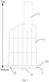
Fig. 1 is a schematic structural diagram of a fume exhaust assembly according to an embodiment of the invention; -
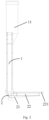
Fig. 2 is a left side view of the fume exhaust assembly shown inFig. 1 ; -
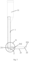
Fig. 3 is a sectional view of the fume exhaust assembly shown inFig. 2 ; -
Fig. 4 is an enlarged view of part A inFig. 3 ; -
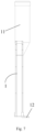
Fig. 5 is a top view of the fume exhaust assembly shown inFig. 1 ; -
Fig. 6 is a schematic structural diagram of a fume exhaust hood shown inFig. 1 ; -
Fig. 7 is a right side view of the fume exhaust hood shown inFIG. 6 ; -
Fig. 8 is a schematic structural diagram of a condensed water collection box shown inFig. 1 ; -
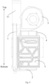
Fig. 9 is a schematic structural diagram of a gas water heater according to an embodiment of this application; -
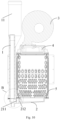
Fig. 10 is a sectional view of the gas water heater shown inFig. 9 ; and -
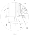
FIG. 11 is an enlarged view of part B inFig. 10 . - The corresponding relationship between the reference numerals and component names in
Fig.s 1 to 11 is as follows. - 1 fume exhaust hood, 11 fume exhaust pipe, 12 rib, 2 condensed water collection box, 21 box body bottom wall, 211 stud, 212 support protrusion, 213 water outlet, 22 box body side wall, 221 flange, 3 fan, 4 burner, 5 heat exchanger.
- The realization of the object of this application, functional characteristics, and advantages will be further described in conjunction with the embodiments and with reference to the accompanying drawings.
- The technical solutions in the embodiments of the invention will be described clearly and completely in conjunction with the drawings in the embodiments of this application.
- It should be noted that if there is a directional indication (such as up, down, left, right, front, back...) in the embodiment of this application, the directional indication is only used to explain the relative positional relationship, movement conditions, etc. among the components in a specific posture (as shown in the drawings), if the specific posture changes, the directional indicator also changes accordingly.
- In addition, if there are descriptions related to "first", "second", etc. in the embodiments of this application, the descriptions of "first", "second", etc. are for descriptive purposes only, and cannot be understood as indicating or implying their relative importance or implicitly indicating the number of indicated technical features. Thus, the features defined as "first" and "second" may include at least one of the features either explicitly or implicitly. In addition, the technical solutions between the various embodiments can be combined with each other, but they must be based on the ability of those skilled in the art to realize. When the combination of technical solutions conflicts with each other or cannot be realized, it should be considered that the combination of such technical solutions does not exist , nor within the scope of protection required by this application.
- Some embodiments of the invention provide a fume exhaust assembly, applied in a gas water heater. As shown in
Figs. 1 to 11 , the fume exhaust assembly includes afume exhaust hood 1, and thefume exhaust hood 1 is provided with afume exhaust pipe 11, and thefume exhaust pipe 11 and thefume exhaust hood 1 are integrally formed. - In this solution, the
fume exhaust pipe 11 and thefume exhaust hood 1 are integrally formed. This design eliminates the assembly work of thefume exhaust pipe 11 and thefume exhaust hood 1, simplifies the assembly process of the gas water heaters, and improves the production efficiency of the gas water heaters. - In any of the above technical solutions, optionally, the
fume exhaust pipe 11 and thefume exhaust hood 1 are formed integrally by injection molding. - In this solution, both the
fume exhaust pipe 11 and thefume exhaust hood 1 are made of plastic materials, and thefume exhaust pipe 11 and thefume exhaust hood 1 are integrated by injection molding, so that the production process of the fume exhaust assembly is simple and the production cost of the fume exhaust assembly is low. - In any of the above technical solutions, the
fume exhaust hood 1 is provided with a cavity, a bottom of the cavity is open, and thefume exhaust pipe 11 is arranged at a top of thefume exhaust hood 1 and is in communication with the cavity. - In any of the above technical solutions, the fume exhaust assembly further includes a condensed
water collection box 2, and thefume exhaust hood 1 is mounted on a top of the condensedwater collection box 2. - The fume exhaust assembly provided by this solution further includes a condensed
water collection box 2. Thefume exhaust hood 1 and aheat exchanger 5 of the gas water heater are installed on a top of the condensedwater collection box 2. The fume formed after the combustion of the air and gas mixture enters theheat exchanger 5 first, and the temperature of the fume decreases and a certain amount of condensate is produced after the heat exchange between the fume and theheat exchanger 5. Then the fume and the condensed water enter the condensedwater collection box 2 through the air outlet of theheat exchanger 5, and then the condensed water is drained from a water outlet 231 at a bottom of the condensedwater collection box 2, while the fume will enter thefume exhaust hood 1 from the condensedwater collection box 2, then enter thefume exhaust pipe 11 from thefume exhaust hood 1, and then discharged through thefume exhaust pipe 11. - In any of the above technical solutions, the condensed
water collection box 2 includes a boxbody bottom wall 21 and a boxbody side wall 22 extending upward from an edge of the boxbody bottom wall 21, the top of the condensedwater collection box 2 is provided with an opening, and a bottom of thefume exhaust hood 1 is connected to a top of the boxbody side wall 22. - In this solution, the condensed
water collection box 2 is a box with an open top, so that the condensedwater collection box 2 has a simple structure and low production and processing difficulty. - In any of the above technical solutions, optionally, the top of the box
body side wall 22 is provided with an outwardlyextended flange 221, and the bottom of thefume exhaust hood 1 is connected to theflange 221 by a screw. - In this solution, the
fume exhaust hood 1 is installed on the condensedwater collection box 2 by screws, so that thefume exhaust hood 1 and the condensedwater collection box 2 has high reliability in connection and fixation, and thefume exhaust hood 1 and the condensedwater collection box 2 are not prone to loosening. Specifically, one of the bottom of the fume exhaust hood and the flange is provided with a stud, and the other is provided with a connection hole. When the fume exhaust hood is installed on the condensed water collection box, the stud is aligned with the connection hole and fixed by screws. - As shown in
Fig. 3 to 11 , the boxbody bottom wall 21 is provided with a support portion including astud 211 and asupport protrusion 212, thefume exhaust hood 1 is provided with arib 12 at a side of the bottom of thefume exhaust hood 1 close to the support portion, therib 12 defines a through hole, therib 12 is abutted against a top of thesupport protrusion 212, the through hole is opposite to thestud 211, aheat exchanger 5 of the gas water heater is connected to thestud 211 by a screw, so that therib 12 is pressed and fixed on thesupport protrusion 212. - In related art, the fume exhaust hood and the heat exchanger are installed on the top of the condensed water collection box, so that the fume exhaust hood, the heat exchanger and the condensed water collection box are communicated. The positions of the fume exhaust hood and the heat exchanger corresponding to the box body side wall are respectively fixedly connected to the box body side wall by screws, and it is necessary to arrange studs on the box body bottom wall for the fume exhaust hood and the heat exchanger respectively, so that the parts of the fume exhaust hood and the heat exchanger located above the box body bottom wall are respectively fixedly connected to the stud by a screw. While a large number of screws are used in this fixing method, resulting in low production and assembly efficiency of gas water heaters. In this solution, the fixing method of the
fume exhaust hood 1 is changed. Asupport protrusion 212 and astud 211 are arranged on a boxbody bottom wall 21 of a condensed water collection box, and arib 12 is arranged on a side of thefume exhaust hood 1 close to thestud 211. When assembling thefume exhaust hood 1, theheat exchanger 5, and the condensedwater collection box 2, first install thefume exhaust hood 1 on the condensedwater collection box 2. A position of thefume exhaust hood 1 corresponding to a boxbody side wall 22 of a condensed water collection box is fixedly connected to the boxbody side wall 22 by screws. Therib 12 of thefume exhaust hood 1 is abutted against thesupport protrusion 212 on the boxbody bottom wall 21, and a through hole on therib 12 is aligned with thestud 211. After thefume exhaust hood 1 is in place, install theheat exchanger 5 on the condensedwater collection box 2. A position of theheat exchanger 5 corresponding to the boxbody side wall 22 is fixedly connected to the boxbody side wall 22 by screws. A part of theheat exchanger 5 located above the boxbody bottom wall 21 is connected to thestud 211 by a screw, so that therib 12 is pressed and fixed on thesupport protrusion 212, thereby completing the assembly of thefume exhaust hood 1, theheat exchanger 5, and the condensedwater collection box 2. This design reduces the number of screws, which can improve the production and assembly efficiency of gas water heaters. - The gas water heater may be a fully premixed condensing gas water heater, as shown in
Fig.s 9 to 11 , the fully premixed condensing gas water heater includes afan 3, aburner 4, aheat exchanger 5 and the fume exhaust assembly provided by any embodiment of the first aspect. An air outlet of thefan 3 is connected to an air inlet of theburner 4, an air outlet of theburner 4 is connected to an air inlet of theheat exchanger 5, and an air outlet of theheat exchanger 5 is connected to an air inlet of the fume exhaust assembly. - Optionally, the heat exchanger of the gas water heater is an integrated condensing heat exchanger consisting of a sensible heat exchanger and a latent heat exchanger. The sensible heat exchanger directly uses the heat generated by the combustion of the gas in the burner to heat water, and the latent heat exchanger exchanges heat with the fume generated by the combustion of the gas, and heats the water through the heat of the fume.
- In the description of this application, it should be noted that the terms "top", "bottom", etc. indicate the orientation or positional relationship based on the orientation or positional relationship shown in the drawings, only for the convenience of describing the present application and simplify the description, rather than indicating or implying that the device or element referred to must have a specific orientation, be constructed and operate in a specific orientation, and therefore cannot be construed as limiting the present application. The terms "connected", "installed", "fixed", etc. should be understood in a broad sense. For example, "connected" can be a fixed connection, a detachable connection, or an integral connection; it can be directly connected or indirectly connected through an intermediary. For those of ordinary skill in the art, the specific meanings of the above-mentioned terms in this application can be understood according to specific circumstances.
- In the description of this specification, the description referring to the terms "one embodiment", "some embodiments", "schematic embodiment", "example", "specific examples", or "some examples" means specific features, structures, materials or characteristics described in conjunction with the embodiment or examples are included in at least one embodiment or example of this application. In this specification, the schematic expression of the above terms does not necessarily refer to the same embodiment or example. Moreover, the specific features, structures, materials, or characteristics described may be combined in any suitable manner in any one or more embodiments or examples.
- The above are only the preferred embodiments of this application, and therefore do not limit the patent scope as defined by the claims.
Claims (5)
- A fume exhaust assembly for a gas water heater, comprising a fume exhaust hood (1), wherein the fume exhaust hood (1) is provided with a fume exhaust pipe (11), wherein the fume exhaust pipe (11) and the fume exhaust hood (1) are integrally formed,wherein an interior of the fume exhaust hood (1) is provided with a cavity, a bottom of the cavity is open, and the fume exhaust pipe (11) is arranged at a top of the fume exhaust hood (1) and is in communication with the cavity,wherein the fume exhaust assembly further comprises a condensed water collection box (2), and the fume exhaust hood (1) is mounted on a top of the condensed water collection box (2),wherein the condensed water collection box (2) comprises a box body bottom wall (21) and a box body side wall (22) extending upward from an edge of the bottom wall (21), the top of the condensed water collection box (2) is provided with an opening, and a bottom of the fume exhaust hood (1) is connected to a top of the box body side wall (22),characterized in that the bottom wall (21) is provided with a support portion comprising a stud (211) and a support protrusion (212), the fume exhaust hood (1) is provided with a rib (12) at a side of the bottom of the fume exhaust hood (1) close to the support portion, the rib (12) is provided with a through hole, the rib (12) is abutted against a top of the support protrusion (212), the through hole is aligned with the stud (211), a heat exchanger (5) of the gas water heater is connected to the stud (211) by a screw, so that the rib (12) is pressed and fixed on the support protrusion (212).
- The fume exhaust assembly of claim 1, wherein the fume exhaust pipe (11) and the fume exhaust hood (1) are formed integrally by injection molding.
- The fume exhaust assembly of any one of claims 1 or 2, characterized in that the top of the box body side wall (22) is provided with an outwardly extended flange (221), and the bottom of the fume exhaust hood (1) is connected to the flange (221) by another screw.
- A gas water heater, characterized by comprising a fume exhaust assembly according to any one of claims 1 to 3.
- The gas water heater of claim 4, characterized by further comprising a fan (3), a burner (4) and a heat exchanger (5), wherein an air outlet of the fan (3) is connected to an air inlet of the burner (4), an air outlet of the burner (4) is connected to an air inlet of the heat exchanger (5), and an air outlet of the heat exchanger (5) is connected to an air inlet of the fume exhaust assembly.
Applications Claiming Priority (2)
| Application Number | Priority Date | Filing Date | Title |
|---|---|---|---|
| CN201820718589.2U CN208295944U (en) | 2018-05-14 | 2018-05-14 | Smoke evacuation component and gas heater |
| PCT/CN2018/119976 WO2019218651A1 (en) | 2018-05-14 | 2018-12-10 | Fume exhaust assembly and gas water heater |
Publications (3)
| Publication Number | Publication Date |
|---|---|
| EP3783261A1 EP3783261A1 (en) | 2021-02-24 |
| EP3783261A4 EP3783261A4 (en) | 2021-04-21 |
| EP3783261B1 true EP3783261B1 (en) | 2025-06-25 |
Family
ID=64727623
Family Applications (1)
| Application Number | Title | Priority Date | Filing Date |
|---|---|---|---|
| EP18919353.5A Active EP3783261B1 (en) | 2018-05-14 | 2018-12-10 | Fume exhaust assembly and gas water heater |
Country Status (5)
| Country | Link |
|---|---|
| US (1) | US11371749B2 (en) |
| EP (1) | EP3783261B1 (en) |
| JP (1) | JP7182645B2 (en) |
| CN (1) | CN208295944U (en) |
| WO (1) | WO2019218651A1 (en) |
Families Citing this family (6)
| Publication number | Priority date | Publication date | Assignee | Title |
|---|---|---|---|---|
| CN112097395A (en) * | 2020-09-29 | 2020-12-18 | 广东万和新电气股份有限公司 | A fully premixed heat exchanger and a gas-fired hot water device having the same |
| CN112113253A (en) * | 2020-10-13 | 2020-12-22 | 佛山市顺德区美的洗涤电器制造有限公司 | Smoke guide pipe of combined stove and combined stove with smoke guide pipe |
| CN115950094A (en) * | 2022-12-30 | 2023-04-11 | 芜湖美的智能厨电制造有限公司 | Heat Exchangers and Water Heaters |
| CN116357961A (en) * | 2023-03-27 | 2023-06-30 | 重庆赛迪热工环保工程技术有限公司 | A multi-fuel rapid switching regenerative combustion system and its operating method |
| CN116538682A (en) * | 2023-04-17 | 2023-08-04 | 青岛经济技术开发区海尔热水器有限公司 | Gas water heater |
| CN116792926A (en) * | 2023-08-24 | 2023-09-22 | 硬创(济宁)控股有限公司 | Gas hanging stove with smoke exhaust ventilation system |
Citations (1)
| Publication number | Priority date | Publication date | Assignee | Title |
|---|---|---|---|---|
| DE3689486T2 (en) * | 1985-08-01 | 1994-07-21 | Raytheon Co | Condensing boiler. |
Family Cites Families (18)
| Publication number | Priority date | Publication date | Assignee | Title |
|---|---|---|---|---|
| US1121957A (en) * | 1911-05-03 | 1914-12-22 | Pietro Vergnani | Melting-furnace. |
| US4481935A (en) * | 1982-12-15 | 1984-11-13 | Arkla Industries, Inc. | Flue pipe connection |
| JPS59172945U (en) * | 1983-05-06 | 1984-11-19 | 株式会社ハ−マン | Water heater |
| EP0226534A1 (en) * | 1985-10-21 | 1987-06-24 | Battelle Memorial Institute | Method of feeding a burner of a boiler with a combustible mixture |
| CA2136479A1 (en) * | 1993-11-24 | 1995-05-25 | Floris Van Dijk | Discharge structure for closed gas appliances |
| JP4090139B2 (en) * | 1999-03-26 | 2008-05-28 | 株式会社ハーマンプロ | Combustion device |
| DE10041258A1 (en) * | 2000-08-23 | 2002-03-07 | Bosch Gmbh Robert | Useful-heat heater with heat exchanger has exhaust gas and condensate collecting bath passing directly through channel in its side wall to exhaust connection |
| CN2739529Y (en) * | 2004-06-08 | 2005-11-09 | 上海帝高燃气电气有限公司 | Displacement gas rapid water heater |
| KR100846584B1 (en) * | 2005-02-05 | 2008-07-16 | 삼성에스디아이 주식회사 | Exhaust Pipe Protection Tip Structure and Plasma Display Module |
| US8156931B2 (en) * | 2005-04-29 | 2012-04-17 | M&G DuraVent, Inc. | Direct vent cap |
| CN201145389Y (en) * | 2007-12-26 | 2008-11-05 | 成都前锋电子有限责任公司 | Condensing gas water heater |
| CN103604215B (en) * | 2013-11-08 | 2016-06-08 | 威能(无锡)供热设备有限公司 | Petticoat pipe and adopt the gas and hot water equipment of this petticoat pipe |
| CN203670302U (en) * | 2014-01-17 | 2014-06-25 | 广东裕祥环保科技有限公司 | Gas water heater fan horizontal forced exhaust fan installation |
| CN204787262U (en) * | 2015-03-31 | 2015-11-18 | 广东万和新电气股份有限公司 | A tub connection structure that discharges fume for condensing gas heater |
| US10605454B2 (en) * | 2015-10-27 | 2020-03-31 | Noritz Corporation | Exhaust structure for combustion apparatus |
| CN205640855U (en) * | 2016-05-03 | 2016-10-12 | 山东银鹤食品机械股份有限公司 | Fuel gas and vapor generator |
| CN106322751B (en) * | 2016-08-31 | 2019-03-01 | 芜湖美的厨卫电器制造有限公司 | Water heater flue components and water heaters |
| CN112212503A (en) * | 2020-10-28 | 2021-01-12 | 东阳普润保温容器有限公司 | Water heater using heat of pipeline of range hood as heat source |
-
2018
- 2018-05-14 CN CN201820718589.2U patent/CN208295944U/en active Active
- 2018-12-10 US US17/055,596 patent/US11371749B2/en active Active
- 2018-12-10 WO PCT/CN2018/119976 patent/WO2019218651A1/en not_active Ceased
- 2018-12-10 JP JP2020564107A patent/JP7182645B2/en active Active
- 2018-12-10 EP EP18919353.5A patent/EP3783261B1/en active Active
Patent Citations (1)
| Publication number | Priority date | Publication date | Assignee | Title |
|---|---|---|---|---|
| DE3689486T2 (en) * | 1985-08-01 | 1994-07-21 | Raytheon Co | Condensing boiler. |
Also Published As
| Publication number | Publication date |
|---|---|
| US20210222912A1 (en) | 2021-07-22 |
| EP3783261A1 (en) | 2021-02-24 |
| WO2019218651A1 (en) | 2019-11-21 |
| EP3783261A4 (en) | 2021-04-21 |
| JP7182645B2 (en) | 2022-12-02 |
| US11371749B2 (en) | 2022-06-28 |
| JP2021523341A (en) | 2021-09-02 |
| CN208295944U (en) | 2018-12-28 |
Similar Documents
| Publication | Publication Date | Title |
|---|---|---|
| EP3783261A1 (en) | Fume exhaust assembly and gas water heater | |
| CN207317119U (en) | Window air conditioner | |
| CN217423623U (en) | Gas water heater and condensation heat exchange device thereof | |
| CN208886927U (en) | A kind of electric heating mounting structure and air conditioner | |
| US12104825B2 (en) | Heat exchanger and water heater | |
| CN217357184U (en) | Evaporator assembly and cabinet air conditioner | |
| CN206037397U (en) | Flue subassembly and water heater of water heater | |
| WO2024198093A1 (en) | Condensing heat exchanger and gas apparatus | |
| CN209877146U (en) | Mounting structure and roof-top machine | |
| CN116952015A (en) | Condensing heat exchanger and gas water heater | |
| CN107965913A (en) | Warm-air drier | |
| CN220871133U (en) | Electric control box installation structure of heat pump water heater and heat pump water heater | |
| CN212204779U (en) | Heat exchanger assembly and air duct machine | |
| CN209386425U (en) | Heat exchanger assembly, air conditioner indoor unit and air conditioner | |
| CN212157621U (en) | Heat exchanger assembly and air duct machine | |
| CN220229568U (en) | Condensing heat exchangers and gas equipment | |
| CN222123297U (en) | Linear heater | |
| CN223216399U (en) | Air conditioner outdoor unit and air conditioner | |
| CN222527904U (en) | Shell structure and air conditioner indoor unit having the same | |
| CN223020435U (en) | Air conditioner outdoor unit and air conditioner with same | |
| CN220898510U (en) | Cavity assembly and cooking device | |
| CN216114619U (en) | Air pipe assembly and mobile air conditioner | |
| CN222925744U (en) | Waste heat recovery device and gas water heater | |
| CN222230832U (en) | Air pipe assembly and air conditioner | |
| CN215175513U (en) | Indoor unit and air conditioner |
Legal Events
| Date | Code | Title | Description |
|---|---|---|---|
| STAA | Information on the status of an ep patent application or granted ep patent |
Free format text: STATUS: THE INTERNATIONAL PUBLICATION HAS BEEN MADE |
|
| PUAI | Public reference made under article 153(3) epc to a published international application that has entered the european phase |
Free format text: ORIGINAL CODE: 0009012 |
|
| STAA | Information on the status of an ep patent application or granted ep patent |
Free format text: STATUS: REQUEST FOR EXAMINATION WAS MADE |
|
| 17P | Request for examination filed |
Effective date: 20201117 |
|
| AK | Designated contracting states |
Kind code of ref document: A1 Designated state(s): AL AT BE BG CH CY CZ DE DK EE ES FI FR GB GR HR HU IE IS IT LI LT LU LV MC MK MT NL NO PL PT RO RS SE SI SK SM TR |
|
| AX | Request for extension of the european patent |
Extension state: BA ME |
|
| A4 | Supplementary search report drawn up and despatched |
Effective date: 20210319 |
|
| RIC1 | Information provided on ipc code assigned before grant |
Ipc: F23J 13/00 20060101AFI20210315BHEP Ipc: F24H 9/00 20060101ALI20210315BHEP |
|
| DAV | Request for validation of the european patent (deleted) | ||
| DAX | Request for extension of the european patent (deleted) | ||
| STAA | Information on the status of an ep patent application or granted ep patent |
Free format text: STATUS: EXAMINATION IS IN PROGRESS |
|
| 17Q | First examination report despatched |
Effective date: 20230315 |
|
| GRAP | Despatch of communication of intention to grant a patent |
Free format text: ORIGINAL CODE: EPIDOSNIGR1 |
|
| STAA | Information on the status of an ep patent application or granted ep patent |
Free format text: STATUS: GRANT OF PATENT IS INTENDED |
|
| INTG | Intention to grant announced |
Effective date: 20250325 |
|
| GRAS | Grant fee paid |
Free format text: ORIGINAL CODE: EPIDOSNIGR3 |
|
| GRAA | (expected) grant |
Free format text: ORIGINAL CODE: 0009210 |
|
| STAA | Information on the status of an ep patent application or granted ep patent |
Free format text: STATUS: THE PATENT HAS BEEN GRANTED |
|
| AK | Designated contracting states |
Kind code of ref document: B1 Designated state(s): AL AT BE BG CH CY CZ DE DK EE ES FI FR GB GR HR HU IE IS IT LI LT LU LV MC MK MT NL NO PL PT RO RS SE SI SK SM TR |
|
| REG | Reference to a national code |
Ref country code: GB Ref legal event code: FG4D |
|
| REG | Reference to a national code |
Ref country code: CH Ref legal event code: EP |
|
| REG | Reference to a national code |
Ref country code: DE Ref legal event code: R096 Ref document number: 602018083047 Country of ref document: DE |
|
| REG | Reference to a national code |
Ref country code: CH Ref legal event code: EP |
|
| REG | Reference to a national code |
Ref country code: IE Ref legal event code: FG4D |
|
| PG25 | Lapsed in a contracting state [announced via postgrant information from national office to epo] |
Ref country code: FI Free format text: LAPSE BECAUSE OF FAILURE TO SUBMIT A TRANSLATION OF THE DESCRIPTION OR TO PAY THE FEE WITHIN THE PRESCRIBED TIME-LIMIT Effective date: 20250625 |
|
| REG | Reference to a national code |
Ref country code: LT Ref legal event code: MG9D |
|
| PG25 | Lapsed in a contracting state [announced via postgrant information from national office to epo] |
Ref country code: GR Free format text: LAPSE BECAUSE OF FAILURE TO SUBMIT A TRANSLATION OF THE DESCRIPTION OR TO PAY THE FEE WITHIN THE PRESCRIBED TIME-LIMIT Effective date: 20250926 Ref country code: NO Free format text: LAPSE BECAUSE OF FAILURE TO SUBMIT A TRANSLATION OF THE DESCRIPTION OR TO PAY THE FEE WITHIN THE PRESCRIBED TIME-LIMIT Effective date: 20250925 |
|
| PG25 | Lapsed in a contracting state [announced via postgrant information from national office to epo] |
Ref country code: BG Free format text: LAPSE BECAUSE OF FAILURE TO SUBMIT A TRANSLATION OF THE DESCRIPTION OR TO PAY THE FEE WITHIN THE PRESCRIBED TIME-LIMIT Effective date: 20250625 |
|
| PG25 | Lapsed in a contracting state [announced via postgrant information from national office to epo] |
Ref country code: HR Free format text: LAPSE BECAUSE OF FAILURE TO SUBMIT A TRANSLATION OF THE DESCRIPTION OR TO PAY THE FEE WITHIN THE PRESCRIBED TIME-LIMIT Effective date: 20250625 |
|
| PG25 | Lapsed in a contracting state [announced via postgrant information from national office to epo] |
Ref country code: RS Free format text: LAPSE BECAUSE OF FAILURE TO SUBMIT A TRANSLATION OF THE DESCRIPTION OR TO PAY THE FEE WITHIN THE PRESCRIBED TIME-LIMIT Effective date: 20250925 |
|
| PG25 | Lapsed in a contracting state [announced via postgrant information from national office to epo] |
Ref country code: LV Free format text: LAPSE BECAUSE OF FAILURE TO SUBMIT A TRANSLATION OF THE DESCRIPTION OR TO PAY THE FEE WITHIN THE PRESCRIBED TIME-LIMIT Effective date: 20250625 |
|
| REG | Reference to a national code |
Ref country code: NL Ref legal event code: MP Effective date: 20250625 |
|
| PG25 | Lapsed in a contracting state [announced via postgrant information from national office to epo] |
Ref country code: NL Free format text: LAPSE BECAUSE OF FAILURE TO SUBMIT A TRANSLATION OF THE DESCRIPTION OR TO PAY THE FEE WITHIN THE PRESCRIBED TIME-LIMIT Effective date: 20250625 |
|
| PG25 | Lapsed in a contracting state [announced via postgrant information from national office to epo] |
Ref country code: PT Free format text: LAPSE BECAUSE OF FAILURE TO SUBMIT A TRANSLATION OF THE DESCRIPTION OR TO PAY THE FEE WITHIN THE PRESCRIBED TIME-LIMIT Effective date: 20251027 |
|
| REG | Reference to a national code |
Ref country code: AT Ref legal event code: MK05 Ref document number: 1806769 Country of ref document: AT Kind code of ref document: T Effective date: 20250625 |
|
| PG25 | Lapsed in a contracting state [announced via postgrant information from national office to epo] |
Ref country code: IS Free format text: LAPSE BECAUSE OF FAILURE TO SUBMIT A TRANSLATION OF THE DESCRIPTION OR TO PAY THE FEE WITHIN THE PRESCRIBED TIME-LIMIT Effective date: 20251025 |
|
| PGFP | Annual fee paid to national office [announced via postgrant information from national office to epo] |
Ref country code: DE Payment date: 20251212 Year of fee payment: 8 |
|
| PGFP | Annual fee paid to national office [announced via postgrant information from national office to epo] |
Ref country code: GB Payment date: 20251211 Year of fee payment: 8 |
|
| PG25 | Lapsed in a contracting state [announced via postgrant information from national office to epo] |
Ref country code: AT Free format text: LAPSE BECAUSE OF FAILURE TO SUBMIT A TRANSLATION OF THE DESCRIPTION OR TO PAY THE FEE WITHIN THE PRESCRIBED TIME-LIMIT Effective date: 20250625 Ref country code: SM Free format text: LAPSE BECAUSE OF FAILURE TO SUBMIT A TRANSLATION OF THE DESCRIPTION OR TO PAY THE FEE WITHIN THE PRESCRIBED TIME-LIMIT Effective date: 20250625 |
|
| PGFP | Annual fee paid to national office [announced via postgrant information from national office to epo] |
Ref country code: FR Payment date: 20251212 Year of fee payment: 8 |
|
| PG25 | Lapsed in a contracting state [announced via postgrant information from national office to epo] |
Ref country code: CZ Free format text: LAPSE BECAUSE OF FAILURE TO SUBMIT A TRANSLATION OF THE DESCRIPTION OR TO PAY THE FEE WITHIN THE PRESCRIBED TIME-LIMIT Effective date: 20250625 |
|
| PG25 | Lapsed in a contracting state [announced via postgrant information from national office to epo] |
Ref country code: PL Free format text: LAPSE BECAUSE OF FAILURE TO SUBMIT A TRANSLATION OF THE DESCRIPTION OR TO PAY THE FEE WITHIN THE PRESCRIBED TIME-LIMIT Effective date: 20250625 |
|
| PG25 | Lapsed in a contracting state [announced via postgrant information from national office to epo] |
Ref country code: EE Free format text: LAPSE BECAUSE OF FAILURE TO SUBMIT A TRANSLATION OF THE DESCRIPTION OR TO PAY THE FEE WITHIN THE PRESCRIBED TIME-LIMIT Effective date: 20250625 |
|
| PG25 | Lapsed in a contracting state [announced via postgrant information from national office to epo] |
Ref country code: SK Free format text: LAPSE BECAUSE OF FAILURE TO SUBMIT A TRANSLATION OF THE DESCRIPTION OR TO PAY THE FEE WITHIN THE PRESCRIBED TIME-LIMIT Effective date: 20250625 |
|
| PG25 | Lapsed in a contracting state [announced via postgrant information from national office to epo] |
Ref country code: ES Free format text: LAPSE BECAUSE OF FAILURE TO SUBMIT A TRANSLATION OF THE DESCRIPTION OR TO PAY THE FEE WITHIN THE PRESCRIBED TIME-LIMIT Effective date: 20250625 |
|
| PG25 | Lapsed in a contracting state [announced via postgrant information from national office to epo] |
Ref country code: RO Free format text: LAPSE BECAUSE OF FAILURE TO SUBMIT A TRANSLATION OF THE DESCRIPTION OR TO PAY THE FEE WITHIN THE PRESCRIBED TIME-LIMIT Effective date: 20250625 |
|
| PG25 | Lapsed in a contracting state [announced via postgrant information from national office to epo] |
Ref country code: DK Free format text: LAPSE BECAUSE OF FAILURE TO SUBMIT A TRANSLATION OF THE DESCRIPTION OR TO PAY THE FEE WITHIN THE PRESCRIBED TIME-LIMIT Effective date: 20250625 |
|
| PG25 | Lapsed in a contracting state [announced via postgrant information from national office to epo] |
Ref country code: IT Free format text: LAPSE BECAUSE OF FAILURE TO SUBMIT A TRANSLATION OF THE DESCRIPTION OR TO PAY THE FEE WITHIN THE PRESCRIBED TIME-LIMIT Effective date: 20250625 |
|
| PLBE | No opposition filed within time limit |
Free format text: ORIGINAL CODE: 0009261 |
|
| STAA | Information on the status of an ep patent application or granted ep patent |
Free format text: STATUS: NO OPPOSITION FILED WITHIN TIME LIMIT |
|
| REG | Reference to a national code |
Ref country code: CH Ref legal event code: L10 Free format text: ST27 STATUS EVENT CODE: U-0-0-L10-L00 (AS PROVIDED BY THE NATIONAL OFFICE) Effective date: 20260507 |