EP3783219A1 - Abnormality diagnostic device for oil jet control valve of internal combustion engine - Google Patents
Abnormality diagnostic device for oil jet control valve of internal combustion engine Download PDFInfo
- Publication number
- EP3783219A1 EP3783219A1 EP20192245.7A EP20192245A EP3783219A1 EP 3783219 A1 EP3783219 A1 EP 3783219A1 EP 20192245 A EP20192245 A EP 20192245A EP 3783219 A1 EP3783219 A1 EP 3783219A1
- Authority
- EP
- European Patent Office
- Prior art keywords
- oil
- oil jet
- gallery
- control valve
- abnormality
- Prior art date
- Legal status (The legal status is an assumption and is not a legal conclusion. Google has not performed a legal analysis and makes no representation as to the accuracy of the status listed.)
- Granted
Links
Images

Classifications
-
- F—MECHANICAL ENGINEERING; LIGHTING; HEATING; WEAPONS; BLASTING
- F02—COMBUSTION ENGINES; HOT-GAS OR COMBUSTION-PRODUCT ENGINE PLANTS
- F02D—CONTROLLING COMBUSTION ENGINES
- F02D41/00—Electrical control of supply of combustible mixture or its constituents
- F02D41/22—Safety or indicating devices for abnormal conditions
- F02D41/221—Safety or indicating devices for abnormal conditions relating to the failure of actuators or electrically driven elements
-
- F—MECHANICAL ENGINEERING; LIGHTING; HEATING; WEAPONS; BLASTING
- F01—MACHINES OR ENGINES IN GENERAL; ENGINE PLANTS IN GENERAL; STEAM ENGINES
- F01M—LUBRICATING OF MACHINES OR ENGINES IN GENERAL; LUBRICATING INTERNAL COMBUSTION ENGINES; CRANKCASE VENTILATING
- F01M1/00—Pressure lubrication
- F01M1/08—Lubricating systems characterised by the provision therein of lubricant jetting means
-
- F—MECHANICAL ENGINEERING; LIGHTING; HEATING; WEAPONS; BLASTING
- F01—MACHINES OR ENGINES IN GENERAL; ENGINE PLANTS IN GENERAL; STEAM ENGINES
- F01M—LUBRICATING OF MACHINES OR ENGINES IN GENERAL; LUBRICATING INTERNAL COMBUSTION ENGINES; CRANKCASE VENTILATING
- F01M1/00—Pressure lubrication
- F01M1/16—Controlling lubricant pressure or quantity
-
- F—MECHANICAL ENGINEERING; LIGHTING; HEATING; WEAPONS; BLASTING
- F02—COMBUSTION ENGINES; HOT-GAS OR COMBUSTION-PRODUCT ENGINE PLANTS
- F02D—CONTROLLING COMBUSTION ENGINES
- F02D17/00—Controlling engines by cutting out individual cylinders; Rendering engines inoperative or idling
- F02D17/04—Controlling engines by cutting out individual cylinders; Rendering engines inoperative or idling rendering engines inoperative or idling, e.g. caused by abnormal conditions
-
- F—MECHANICAL ENGINEERING; LIGHTING; HEATING; WEAPONS; BLASTING
- F02—COMBUSTION ENGINES; HOT-GAS OR COMBUSTION-PRODUCT ENGINE PLANTS
- F02D—CONTROLLING COMBUSTION ENGINES
- F02D2200/00—Input parameters for engine control
- F02D2200/02—Input parameters for engine control the parameters being related to the engine
- F02D2200/023—Temperature of lubricating oil or working fluid
-
- F—MECHANICAL ENGINEERING; LIGHTING; HEATING; WEAPONS; BLASTING
- F02—COMBUSTION ENGINES; HOT-GAS OR COMBUSTION-PRODUCT ENGINE PLANTS
- F02D—CONTROLLING COMBUSTION ENGINES
- F02D2200/00—Input parameters for engine control
- F02D2200/02—Input parameters for engine control the parameters being related to the engine
- F02D2200/024—Fluid pressure of lubricating oil or working fluid
-
- F—MECHANICAL ENGINEERING; LIGHTING; HEATING; WEAPONS; BLASTING
- F02—COMBUSTION ENGINES; HOT-GAS OR COMBUSTION-PRODUCT ENGINE PLANTS
- F02D—CONTROLLING COMBUSTION ENGINES
- F02D2200/00—Input parameters for engine control
- F02D2200/02—Input parameters for engine control the parameters being related to the engine
- F02D2200/10—Parameters related to the engine output, e.g. engine torque or engine speed
- F02D2200/101—Engine speed
-
- F—MECHANICAL ENGINEERING; LIGHTING; HEATING; WEAPONS; BLASTING
- F02—COMBUSTION ENGINES; HOT-GAS OR COMBUSTION-PRODUCT ENGINE PLANTS
- F02D—CONTROLLING COMBUSTION ENGINES
- F02D2200/00—Input parameters for engine control
- F02D2200/02—Input parameters for engine control the parameters being related to the engine
- F02D2200/10—Parameters related to the engine output, e.g. engine torque or engine speed
- F02D2200/1012—Engine speed gradient
-
- F—MECHANICAL ENGINEERING; LIGHTING; HEATING; WEAPONS; BLASTING
- F02—COMBUSTION ENGINES; HOT-GAS OR COMBUSTION-PRODUCT ENGINE PLANTS
- F02D—CONTROLLING COMBUSTION ENGINES
- F02D41/00—Electrical control of supply of combustible mixture or its constituents
- F02D41/02—Circuit arrangements for generating control signals
- F02D41/04—Introducing corrections for particular operating conditions
- F02D41/12—Introducing corrections for particular operating conditions for deceleration
- F02D41/123—Introducing corrections for particular operating conditions for deceleration the fuel injection being cut-off
-
- Y—GENERAL TAGGING OF NEW TECHNOLOGICAL DEVELOPMENTS; GENERAL TAGGING OF CROSS-SECTIONAL TECHNOLOGIES SPANNING OVER SEVERAL SECTIONS OF THE IPC; TECHNICAL SUBJECTS COVERED BY FORMER USPC CROSS-REFERENCE ART COLLECTIONS [XRACs] AND DIGESTS
- Y02—TECHNOLOGIES OR APPLICATIONS FOR MITIGATION OR ADAPTATION AGAINST CLIMATE CHANGE
- Y02T—CLIMATE CHANGE MITIGATION TECHNOLOGIES RELATED TO TRANSPORTATION
- Y02T10/00—Road transport of goods or passengers
- Y02T10/10—Internal combustion engine [ICE] based vehicles
- Y02T10/40—Engine management systems
Definitions
- the present invention relates to an abnormality diagnostic device for an oil jet control valve of an internal combustion engine.
- Patent Literature 1 discloses a technique of performing abnormality diagnosis for an oil jet based on a change in engine rotation speed at a time when an operating state of the oil jet is controlled to be ON and OFF during idling operation.
- Patent Literature 1 JP-A-2013-209915
- an object of the present invention is to provide an abnormality diagnostic device for an oil jet control valve of an internal combustion engine which is capable of improving accuracy of abnormality diagnosis for an oil jet.
- the present invention provides an abnormality diagnostic device for an oil jet control valve of an internal combustion engine, the abnormality diagnostic device including:
- the abnormality diagnostic device for an oil jet control valve of an internal combustion engine can improve the accuracy of abnormality diagnosis for an oil jet.
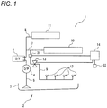
- a vehicle 1 on which an abnormality diagnostic device for an oil jet control valve of an internal combustion engine according to an embodiment of the present invention is mounted, includes an engine 2 as an internal combustion engine and a control unit 14.
- the engine 2 includes at least one cylinder.
- the engine 2 is a straight-four engine including four cylinders.
- a number of the cylinder is not limited to four.
- the engine 2 includes a cylinder block (not shown), a cylinder head (not shown) fastened to an upper portion of the cylinder block, and an oil pan 3 fastened to a lower portion of the cylinder block. Oil (not shown) is stored in the oil pan 3.
- a cylinder serving as a cylinder of the engine 2 (not shown) is formed in the cylinder block.
- a piston (not shown) that can vertically reciprocate in the cylinder is housed in the cylinder.
- the engine 2 is a so-called 4-cycle gasoline engine that performs a series of four strokes including an intake stroke, a compression stroke, an expansion stroke, and an exhaust stroke while the piston reciprocates twice in the cylinder.
- An oil pump 4 sucks up the oil stored in the oil pan 3 via a strainer 5.
- the oil pump 4 for example, a mechanical pump that is driven by using output of the engine 2 is used.
- An oil filter 6 filters oil discharged from the oil pump 4.
- the oil discharged from the oil pump 4 flows through the oil filter 6 to 3 systems of oil gallery, that is, a main gallery 7, a head gallery 8, and an oil jet gallery 9.
- the oil distributed to the main gallery 7 is supplied to each main bearing 10 that supports a crankshaft (not shown).
- the oil distributed to the head gallery 8 is supplied to a valve mechanism 11 that is configured with a camshaft, an intake valve, an exhaust valve, and the like.
- the oil distributed through an oil jet valve 13 serving as a control valve to the oil jet gallery 9 is supplied to each oil jet 12.
- the oil jet 12 injects the oil toward the piston of the engine 2.
- An injection quantity of the oil injected from an injection nozzle of the oil jet 12 changes according to supply pressure of the oil.
- the oil jet valve 13 controls a supply flow rate and the supply pressure of the oil that is supplied from the oil pump 4 to the oil jet 12. Opening and closing of the oil jet valve 13 are controlled by the control unit 14.
- An oil temperature and pressure sensor 31 serving as an oil pressure sensor is provided between the oil jet valve 13 and the main gallery 7 that is upstream of the oil jet valve 13 in a direction in which the oil flows.
- the control unit 14 is configured with a computer unit that includes a central processing unit (CPU), a random access memory (RAM), a read only memory (ROM), a flash memory, an input port, and an output port.
- CPU central processing unit
- RAM random access memory
- ROM read only memory
- flash memory an input port, and an output port.
- programs for causing the computer unit to function as the control unit 14 are stored together with various control constants, various maps, and the like. That is, the computer unit functions as the control unit 14 by the CPU executing a program stored in the ROM.
- various sensors such as an engine rotation speed sensor 32 are connected to the input port of the control unit 14.
- the engine rotation speed sensor 32 Based on rotation of a crankshaft of the engine 2, the engine rotation speed sensor 32 outputs an engine rotation speed pulse signal having a number of pulses proportional to a rotation speed of the crankshaft.
- the control unit 14 can detect the engine rotation speed based on the engine rotation speed pulse signal.
- control unit 14 diagnoses an abnormality of the oil jet valve 13.
- the control unit 14 perform an abnormality diagnosis control for determining an abnormality of the oil jet valve 13 in a fuel-cut operation state of the engine 2.
- control unit 14 sets the oil jet valve 13 to an open state in the fuel-cut operation state of the engine 2, and sets the oil jet valve 13 to a closed state after a predetermined period of time elapses in which oil pressure of the oil jet gallery 9 is stabilized.
- the control unit 14 determines that there is the abnormality in the oil jet valve 13.
- control unit 14 may perform the abnormality diagnosis control of the oil jet valve 13 when the oil pressure of the oil jet gallery 9 is lower than a predetermined value or when the engine rotation speed is lower than a predetermined rotation speed.
- the control unit 14 may perform the abnormality diagnosis control of the oil jet valve 13 when a decreasing gradient (change amount) of the engine rotation speed is smaller than a predetermined change amount.
- the control unit 14 may fix duty of the oil pump 4 before the abnormality diagnosis control of the oil jet valve 13 is performed.
- the control unit 14 prohibits the abnormality diagnosis control of the oil jet valve 13.
- Abnormality diagnosis processing by the abnormality diagnostic device for an oil jet control valve of an internal combustion engine according to the present embodiment which is configured as described above will be described with reference to Fig. 2 .
- the abnormality diagnosis processing to be described below is started when the control unit 14 starts operations, and is executed at a preset time interval.
- step S1 the control unit 14 determines whether an oil temperature of the oil jet gallery 9 is lower than a predetermined temperature. When it is determined that the oil temperature of the oil jet gallery 9 is lower than the predetermined temperature, the control unit 14 ends the processing.
- control unit 14 determines in step S2 whether the engine 2 is in a fuel-cut operation state. When it is determined that the engine 2 is not in the fuel-cut operation state, the control unit 14 ends the processing.
- control unit 14 determines in step S3 whether oil pressure of the oil jet gallery 9 is lower than a predetermined value.
- control unit 14 determines in step S4 whether an engine rotation speed is lower than a predetermined rotation speed. When it is determined that the engine rotation speed is not lower than the predetermined rotation speed, the control unit 14 ends the processing.
- step S3 When it is determined in step S3 that the oil pressure of the oil jet gallery 9 is lower than the predetermined value or when it is determined in step S4 that the engine rotation speed is lower than the predetermined rotation speed, the control unit 14 fixes duty of the oil pump 4 in step S5.
- step S6 the control unit 14 opens the oil jet valve 13.
- step S7 the control unit 14 acquires the oil pressure of the oil jet gallery 9 by the oil temperature and pressure sensor 31.
- step S8 the control unit 14 determines whether a predetermined period of time elapses in which the oil pressure of the oil jet gallery 9 is stabilized. When it is determined that the predetermined period of time does not elapse, the control unit 14 repeats the process of step S8.
- step S9 the control unit 14 closes the oil jet valve 13.
- step S10 the control unit 14 acquires the oil pressure of the oil jet gallery 9 by the oil temperature and pressure sensor 31.
- step S11 the control unit 14 determines whether a difference between the oil pressure of the oil jet gallery 9 at the time when the oil jet valve 13 is opened and the oil pressure of the oil jet gallery 9 at the time when the oil jet valve 13 is closed is smaller than a predetermined difference.
- control unit 14 determines in step S12 that there is an abnormality in the oil jet valve 13, and ends the processing.
- control unit 14 determines in step S13 that there is no abnormality in the oil jet valve 13, and ends the processing.
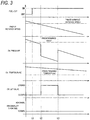
- Fig. 3 illustrates a case where it is determined that there is no abnormality in the oil jet valve 13.
- the engine 2 When at a time point t1, the engine 2 is set to the fuel-cut operation state.
- the oil pressure of the oil jet gallery 9 is lower than the predetermined value, and the oil temperature of the oil jet gallery 9 is equal to or higher than the predetermined temperature, the oil jet valve 13 is opened and the oil pressure of the oil jet gallery 9 is acquired.
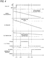
- Fig. 4 illustrates a case where it is determined that the oil jet valve 13 is abnormal.
- the engine 2 When at a time point t11, the engine 2 is set to the fuel-cut operation state.
- the oil pressure of the oil jet gallery 9 is lower than the predetermined value, and the oil temperature of the oil jet gallery 9 is equal to or higher than the predetermined temperature, the oil jet valve 13 is opened and the oil pressure of the oil jet gallery 9 is acquired.
- oil pressure of the oil jet gallery 9 When the oil pressure of the oil jet gallery 9 is equal to or greater than the predetermined value, oil cannot be supplied from the oil pump 4 at a stable oil pressure, and thus the oil pressure of the oil jet gallery 9 may become unstable.
- the accuracy of the abnormality diagnosis can be improved.
- a condition is considered in which viscosity of the oil increases when the oil is in a low temperature state and the oil pressure difference is unlikely to occur. Therefore, by prohibiting the abnormality diagnosis when the oil temperature of the oil jet gallery 9 is lower than the predetermined temperature, the accuracy of the abnormality diagnosis can be improved.
- the duty of the oil pump 4 is fixed. Therefore, by fixing the duty of the oil pump 4 and reducing the oil pressure, the accuracy of the abnormality diagnosis can be improved.
- the vehicle 1 may include a communication unit that is capable of communicating with a device outside the vehicle such as an external server, the various determinations and calculations may be performed by the device outside the vehicle based on detection information of various sensors which is transmitted from the communication unit, the communication unit may receive determination results and calculation results, and various types of control may be performed using the received determination results and calculation results.
Landscapes
- Engineering & Computer Science (AREA)
- Mechanical Engineering (AREA)
- General Engineering & Computer Science (AREA)
- Chemical & Material Sciences (AREA)
- Combustion & Propulsion (AREA)
- Lubrication Of Internal Combustion Engines (AREA)
Abstract
Description
- The present invention relates to an abnormality diagnostic device for an oil jet control valve of an internal combustion engine.
-
Patent Literature 1 discloses a technique of performing abnormality diagnosis for an oil jet based on a change in engine rotation speed at a time when an operating state of the oil jet is controlled to be ON and OFF during idling operation. - Patent Literature 1:
JP-A-2013-209915 - However, when load of an engine changes due to drive of an auxiliary machine or the like during the idling operation, it is considered that the engine rotation speed may become unstable, and that the abnormality diagnosis for the oil jet cannot be performed accurately.
- Therefore, an object of the present invention is to provide an abnormality diagnostic device for an oil jet control valve of an internal combustion engine which is capable of improving accuracy of abnormality diagnosis for an oil jet.
- In order to solve the above problems, the present invention provides an abnormality diagnostic device for an oil jet control valve of an internal combustion engine, the abnormality diagnostic device including:
- an oil pump that is driven by rotation of an internal combustion engine;
- an oil jet that injects oil toward a piston of the internal combustion engine;
- an oil jet gallery that sends oil from the oil pump to the oil jet;
- a control valve that is disposed at the oil jet gallery and controls flow of oil to the oil jet;
- an oil pressure sensor that is provided upstream of the control valve in the oil jet gallery; and
- a control unit that controls opening and closing of the control valve, wherein
- the control unit performs abnormality diagnosis control for determining an abnormality in the control valve, in a case where the internal combustion engine is in a fuel-cut operation state and a predetermined condition is satisfied, and
- in the abnormality diagnosis control, the control unit sets the control valve to an opened state, and sets the control valve to a closed state after a predetermined period of time elapses in which oil pressure of the oil jet gallery is stabilized, and determines that there is the abnormality in the control valve when a difference between oil pressure of the oil jet gallery at a time when the control valve is opened and oil pressure of the oil jet gallery at time when the control valve is closed after the predetermined period of time elapses is smaller than a predetermined difference.
- As described, according to the present invention, accuracy of abnormality diagnosis for an oil jet can be improved.
-
- [
Fig. 1] Fig. 1 is a schematic configuration diagram of an abnormality diagnostic device for an oil jet control valve of an internal combustion engine according to an embodiment of the present invention. - [
Fig. 2] Fig. 2 is a flowchart illustrating a procedure of abnormality diagnosis processing of an abnormality diagnostic device for an oil jet control valve of an internal combustion engine according to an embodiment of the present invention. - [
Fig. 3] Fig. 3 is a time chart illustrating a change in oil pressure of an oil jet gallery in a case where an oil jet valve is diagnosed as normal by abnormality diagnosis processing of an abnormality diagnostic device for an oil jet control valve of an internal combustion engine according to an embodiment of the present invention. - [
Fig. 4] Fig. 4 is a time chart illustrating a change in oil pressure of an oil jet gallery in a case where an oil jet valve is diagnosed as abnormal by abnormality diagnosis processing of an abnormality diagnostic device for an oil jet control valve of an internal combustion engine according to an embodiment of the present invention. - An abnormality diagnostic device for an oil jet control valve of an internal combustion engine according to an embodiment of the present invention includes:
- an oil pump that is driven by rotation of an internal combustion engine;
- an oil jet that injects oil toward a piston of the internal combustion engine;
- an oil jet gallery that sends oil from the oil pump to the oil jet;
- a control valve that is disposed at the oil jet gallery and controls flow of oil to the oil jet;
- an oil pressure sensor that is provided upstream of the control valve in the oil jet gallery; and
- a control unit that controls opening and closing of the control valve, wherein
- the control unit performs abnormality diagnosis control for determining an abnormality in the control valve, in a case where the internal combustion engine is in a fuel-cut operation state and a predetermined condition is satisfied, and
- in the abnormality diagnosis control, the control unit sets the control valve to an opened state, and sets the control valve to a closed state after a predetermined period of time elapses in which oil pressure of the oil jet gallery is stabilized, and determines that there is the abnormality in the control valve when a difference between oil pressure of the oil jet gallery at a time when the control valve is opened and oil pressure of the oil jet gallery at time when the control valve is closed after the predetermined period of time elapses is smaller than a predetermined difference.
- Accordingly, the abnormality diagnostic device for an oil jet control valve of an internal combustion engine according to an embodiment of the present invention can improve the accuracy of abnormality diagnosis for an oil jet.
- Hereinafter, an abnormality diagnostic device for an oil jet control valve of an internal combustion engine according to an embodiment of the present invention will be described in detail with reference to the drawings.
- In
Fig. 1 , avehicle 1, on which an abnormality diagnostic device for an oil jet control valve of an internal combustion engine according to an embodiment of the present invention is mounted, includes anengine 2 as an internal combustion engine and acontrol unit 14. - The
engine 2 includes at least one cylinder. For example, theengine 2 is a straight-four engine including four cylinders. A number of the cylinder is not limited to four. - The
engine 2 includes a cylinder block (not shown), a cylinder head (not shown) fastened to an upper portion of the cylinder block, and anoil pan 3 fastened to a lower portion of the cylinder block. Oil (not shown) is stored in theoil pan 3. - A cylinder serving as a cylinder of the engine 2 (not shown) is formed in the cylinder block. A piston (not shown) that can vertically reciprocate in the cylinder is housed in the cylinder.
- The
engine 2 is a so-called 4-cycle gasoline engine that performs a series of four strokes including an intake stroke, a compression stroke, an expansion stroke, and an exhaust stroke while the piston reciprocates twice in the cylinder. - An
oil pump 4 sucks up the oil stored in theoil pan 3 via astrainer 5. As theoil pump 4, for example, a mechanical pump that is driven by using output of theengine 2 is used. - An
oil filter 6 filters oil discharged from theoil pump 4.
The oil discharged from theoil pump 4 flows through theoil filter 6 to 3 systems of oil gallery, that is, amain gallery 7, ahead gallery 8, and anoil jet gallery 9. - The oil distributed to the
main gallery 7 is supplied to each main bearing 10 that supports a crankshaft (not shown). - The oil distributed to the
head gallery 8 is supplied to avalve mechanism 11 that is configured with a camshaft, an intake valve, an exhaust valve, and the like. - The oil distributed through an
oil jet valve 13 serving as a control valve to theoil jet gallery 9 is supplied to eachoil jet 12. - The
oil jet 12 injects the oil toward the piston of theengine 2. An injection quantity of the oil injected from an injection nozzle of theoil jet 12 changes according to supply pressure of the oil. - The
oil jet valve 13 controls a supply flow rate and the supply pressure of the oil that is supplied from theoil pump 4 to theoil jet 12. Opening and closing of theoil jet valve 13 are controlled by thecontrol unit 14. - An oil temperature and
pressure sensor 31 serving as an oil pressure sensor is provided between theoil jet valve 13 and themain gallery 7 that is upstream of theoil jet valve 13 in a direction in which the oil flows. - The
control unit 14 is configured with a computer unit that includes a central processing unit (CPU), a random access memory (RAM), a read only memory (ROM), a flash memory, an input port, and an output port. - In the ROM of the computer unit, programs for causing the computer unit to function as the
control unit 14 are stored together with various control constants, various maps, and the like. That is, the computer unit functions as thecontrol unit 14 by the CPU executing a program stored in the ROM. - In addition to the oil temperature and
pressure sensor 31, various sensors such as an enginerotation speed sensor 32 are connected to the input port of thecontrol unit 14. - Based on rotation of a crankshaft of the
engine 2, the enginerotation speed sensor 32 outputs an engine rotation speed pulse signal having a number of pulses proportional to a rotation speed of the crankshaft. Thecontrol unit 14 can detect the engine rotation speed based on the engine rotation speed pulse signal. - On the other hand, various control targets such as the
oil jet valve 13 described above are connected to the output port of thecontrol unit 14. - In the present embodiment, the
control unit 14 diagnoses an abnormality of theoil jet valve 13. - The
control unit 14 perform an abnormality diagnosis control for determining an abnormality of theoil jet valve 13 in a fuel-cut operation state of theengine 2. - In the abnormality diagnosis control, the
control unit 14 sets theoil jet valve 13 to an open state in the fuel-cut operation state of theengine 2, and sets theoil jet valve 13 to a closed state after a predetermined period of time elapses in which oil pressure of theoil jet gallery 9 is stabilized. - In the abnormality diagnosis control, when a difference at this time between oil pressure of the
oil jet gallery 9 at a time when theoil jet valve 13 is set to the opened state and oil pressure of theoil jet gallery 9 at a time when theoil jet valve 13 is set to the closed state is smaller than a predetermined difference, thecontrol unit 14 determines that there is the abnormality in theoil jet valve 13. - In the fuel-cut operation state of the
engine 2, thecontrol unit 14 may perform the abnormality diagnosis control of theoil jet valve 13 when the oil pressure of theoil jet gallery 9 is lower than a predetermined value or when the engine rotation speed is lower than a predetermined rotation speed. - The
control unit 14 may perform the abnormality diagnosis control of theoil jet valve 13 when a decreasing gradient (change amount) of the engine rotation speed is smaller than a predetermined change amount. - The
control unit 14 may fix duty of theoil pump 4 before the abnormality diagnosis control of theoil jet valve 13 is performed. - When an oil temperature of the
oil jet gallery 9 is lower than a predetermined temperature, thecontrol unit 14 prohibits the abnormality diagnosis control of theoil jet valve 13. - Abnormality diagnosis processing by the abnormality diagnostic device for an oil jet control valve of an internal combustion engine according to the present embodiment which is configured as described above will be described with reference to
Fig. 2 . The abnormality diagnosis processing to be described below is started when thecontrol unit 14 starts operations, and is executed at a preset time interval. - In step S1, the
control unit 14 determines whether an oil temperature of theoil jet gallery 9 is lower than a predetermined temperature. When it is determined that the oil temperature of theoil jet gallery 9 is lower than the predetermined temperature, thecontrol unit 14 ends the processing. - When it is determined that the oil temperature of the
oil jet gallery 9 is not lower than the predetermined temperature, thecontrol unit 14 determines in step S2 whether theengine 2 is in a fuel-cut operation state. When it is determined that theengine 2 is not in the fuel-cut operation state, thecontrol unit 14 ends the processing. - When it is determined that the
engine 2 is in the fuel-cut operation state, thecontrol unit 14 determines in step S3 whether oil pressure of theoil jet gallery 9 is lower than a predetermined value. - When it is determined that the oil pressure of the
oil jet gallery 9 is not lower than the predetermined value, thecontrol unit 14 determines in step S4 whether an engine rotation speed is lower than a predetermined rotation speed. When it is determined that the engine rotation speed is not lower than the predetermined rotation speed, thecontrol unit 14 ends the processing. - When it is determined in step S3 that the oil pressure of the
oil jet gallery 9 is lower than the predetermined value or when it is determined in step S4 that the engine rotation speed is lower than the predetermined rotation speed, thecontrol unit 14 fixes duty of theoil pump 4 in step S5. - In step S6, the
control unit 14 opens theoil jet valve 13.
In step S7, thecontrol unit 14 acquires the oil pressure of theoil jet gallery 9 by the oil temperature andpressure sensor 31. - In step S8, the
control unit 14 determines whether a predetermined period of time elapses in which the oil pressure of theoil jet gallery 9 is stabilized. When it is determined that the predetermined period of time does not elapse, thecontrol unit 14 repeats the process of step S8. - When it is determined that the predetermined time has elapsed, in step S9, the
control unit 14 closes theoil jet valve 13. - In step S10, the
control unit 14 acquires the oil pressure of theoil jet gallery 9 by the oil temperature andpressure sensor 31. - In step S11, the
control unit 14 determines whether a difference between the oil pressure of theoil jet gallery 9 at the time when theoil jet valve 13 is opened and the oil pressure of theoil jet gallery 9 at the time when theoil jet valve 13 is closed is smaller than a predetermined difference. - When it is determined that the difference between the oil pressure of the
oil jet gallery 9 at the time when theoil jet valve 13 is opened and the oil pressure of theoil jet gallery 9 at the time when theoil jet valve 13 is closed is smaller than the predetermined difference, thecontrol unit 14 determines in step S12 that there is an abnormality in theoil jet valve 13, and ends the processing. - When it is determined that the difference between the oil pressure of the
oil jet gallery 9 at the time when theoil jet valve 13 is opened and the oil pressure of theoil jet gallery 9 at the time when theoil jet valve 13 is closed is not smaller than the predetermined difference, thecontrol unit 14 determines in step S13 that there is no abnormality in theoil jet valve 13, and ends the processing. - The operations of such abnormality diagnosis processing will be described with reference to
Figs. 3 and4 .Fig. 3 illustrates a case where it is determined that there is no abnormality in theoil jet valve 13. - When at a time point t1, the
engine 2 is set to the fuel-cut operation state. At a time point t2 after the time point t1, when the engine rotation speed is lower than the predetermined rotation speed, the oil pressure of theoil jet gallery 9 is lower than the predetermined value, and the oil temperature of theoil jet gallery 9 is equal to or higher than the predetermined temperature, theoil jet valve 13 is opened and the oil pressure of theoil jet gallery 9 is acquired. - Thereafter, at a time point t3 after elapse of the predetermined period of time in which the oil pressure of the
oil jet gallery 9 is stabilized, theoil jet valve 13 is closed and the oil pressure of theoil jet gallery 9 is acquired. - Since the difference between the oil pressure of the
oil jet gallery 9 after opening of theoil jet valve 13 at the time point t2 and the oil pressure of theoil jet gallery 9 after closing of theoil jet valve 13 at the time point t3 is equal to or larger than the predetermined difference, it is determined that theoil jet valve 13 is normal. -
Fig. 4 illustrates a case where it is determined that theoil jet valve 13 is abnormal. - When at a time point t11, the
engine 2 is set to the fuel-cut operation state. At atime point 12 after the time point t11, when the engine rotation speed is lower than the predetermined rotation speed, the oil pressure of theoil jet gallery 9 is lower than the predetermined value, and the oil temperature of theoil jet gallery 9 is equal to or higher than the predetermined temperature, theoil jet valve 13 is opened and the oil pressure of theoil jet gallery 9 is acquired. - Thereafter, at a time point t13 after elapse of the predetermined period of time in which the oil pressure of the
oil jet gallery 9 is stabilized, theoil jet valve 13 is closed and the oil pressure of theoil jet gallery 9 is acquired. - Since the difference between the oil pressure of the
oil jet gallery 9 after opening of theoil jet valve 13 at the time point t12 and the oil pressure of theoil jet gallery 9 after closing of theoil jet valve 13 at the time point t13 is smaller than the predetermined difference, it is determined at a time point t14 that theoil jet valve 13 is abnormal. - As described in the present embodiment, in the case of fuel-cut operation state of the
engine 2, when the difference, between the oil pressure of theoil jet gallery 9 at the time when theoil jet valve 13 is in an opened state and the oil pressure of theoil jet gallery 9 at the time when theoil jet valve 13 is in a closed state after the predetermined period of time elapses in which the oil pressure of theoil jet gallery 9 is stabilized, is smaller than the predetermined difference, it is determined that there is an abnormality in theoil jet valve 13. - By performing the abnormality diagnosis for the
oil jet valve 13 during fuel-cut in which combustion in theengine 2 is not performed, not during idling operation in which the engine rotation speed is not stabilized, the influence of rotational fluctuation due to combustion can be eliminated, and the accuracy of the abnormality diagnosis can be improved. - In addition, instead of the engine rotation speed, by using the difference in the oil pressure of the
oil jet gallery 9 for determination of the abnormality diagnosis, the accuracy of the abnormality diagnosis can be improved. - Further, if the
oil jet valve 13 is normal, a difference in the oil pressure of theoil jet gallery 9 occurs at the opened state and the closed state of theoil jet valve 13, and the oil pressure of theoil jet gallery 9 gradually decreases accompanying decrease of the rotation speed ofengine 2 during fuel-cut, therefore it is difficult to determine, at the time when the oil jet valve13 is opened after being closed, whether the oil pressure of theoil jet gallery 9 is decreasing due to closing and opening of theoil jet valve 13 or whether the oil pressure of theoil jet gallery 9 is decreasing due to decrease of the engine rotation speed, and an erroneous determination may be made. - Therefore, by using for the determination the oil pressure difference caused by rise of the oil pressure of the
oil jet gallery 9 at the time when theoil jet valve 13 is closed after being opened, the accuracy of the abnormality diagnosis can be improved. - In addition, in the fuel-cut operation state of the
engine 2, when the oil pressure of theoil jet gallery 9 is lower than the predetermined value or when the engine rotation speed is lower than the predetermined rotation speed, an abnormality of theoil jet valve 13 is diagnosed. - When the oil pressure of the
oil jet gallery 9 is equal to or greater than the predetermined value, oil cannot be supplied from theoil pump 4 at a stable oil pressure, and thus the oil pressure of theoil jet gallery 9 may become unstable. - Even when the engine rotation speed is equal to or greater than the predetermined rotation speed, the oil cannot be supplied from the
oil pump 4 at a stable oil pressure, and the oil pressure of theoil jet gallery 9 may become unstable. - By performing the abnormality diagnosis in a state in which the oil can be supplied from the
oil pump 4 at a stable oil pressure, the accuracy of the abnormality diagnosis can be improved. - When a change amount of the engine rotation speed is smaller than a predetermined change amount, an abnormality of the
oil jet valve 13 is diagnosed. - Since a change amount in the oil pressure of the
oil jet gallery 9 is also increased when the change amount of the engine rotation speed is large, the change in the oil pressure of theoil jet gallery 9 accompanying the opening and closing of theoil jet valve 13 may be erroneously determined. - Therefore, by performing the abnormality diagnosis when the change amount of the engine rotation speed is smaller than the predetermined change amount, the accuracy of the abnormality diagnosis can be improved.
- When the oil temperature of the
oil jet gallery 9 is lower than the predetermined temperature, the abnormality diagnosis for theoil jet valve 13 is prohibited. - A condition is considered in which viscosity of the oil increases when the oil is in a low temperature state and the oil pressure difference is unlikely to occur. Therefore, by prohibiting the abnormality diagnosis when the oil temperature of the
oil jet gallery 9 is lower than the predetermined temperature, the accuracy of the abnormality diagnosis can be improved. - Before the abnormality diagnosis for the
oil jet valve 13 is performed, the duty of theoil pump 4 is fixed. Therefore, by fixing the duty of theoil pump 4 and reducing the oil pressure, the accuracy of the abnormality diagnosis can be improved. - Although an example, in which the
control unit 14 performs various determinations and calculations based on various kinds of sensor information, is described in the present embodiment, the present invention is not limited thereto. Thevehicle 1 may include a communication unit that is capable of communicating with a device outside the vehicle such as an external server, the various determinations and calculations may be performed by the device outside the vehicle based on detection information of various sensors which is transmitted from the communication unit, the communication unit may receive determination results and calculation results, and various types of control may be performed using the received determination results and calculation results. - Although an embodiment of the present invention has been disclosed, it will be apparent to those skilled in the art that modifications can be made without departing from the scope of the present invention. It is intended that all such modifications and equivalents are included in the following claims.
-
- 1
- vehicle
- 2
- engine (internal combustion engine)
- 4
- oil pump
- 9
- oil jet gallery
- 12
- oil jet
- 13
- oil jet valve (control valve)
- 14
- control unit
- 31
- oil temperature and pressure sensor (oil pressure sensor)
- 32
- engine rotation speed sensor
Claims (4)
- An abnormality diagnostic device for an oil jet control valve of an internal combustion engine, the abnormality diagnostic device comprising:an oil pump (4) that is driven by rotation of an internal combustion engine (2);an oil jet (12) that injects oil toward a piston of the internal combustion engine (2);an oil jet gallery (9) that sends oil from the oil pump (4) to the oil jet (12);a control valve (13) that is disposed at the oil jet gallery (9) and controls flow of oil to the oil jet (12);an oil pressure sensor (31) that is provided upstream of the control valve (13) in the oil jet gallery (9); anda control unit (14) that controls opening and closing of the control valve (13),characterized in thatthe control unit (14) performs abnormality diagnosis control for determining an abnormality in the control valve (13), in a case where the internal combustion engine (2) is in a fuel-cut operation state and a predetermined condition is satisfied, andin the abnormality diagnosis control, the control unit (14) sets the control valve (13) to an opened state, and sets the control valve (13) to a closed state after a predetermined period of time elapses in which oil pressure of the oil jet gallery (9) is stabilized, and determines that there is the abnormality in the control valve (13) when a difference between oil pressure of the oil jet gallery (9) at a time when the control valve (13) is opened and oil pressure of the oil jet gallery (9) at time when the control valve (13) is closed after the predetermined period of time elapses is smaller than a predetermined difference.
- The abnormality diagnostic device for an oil jet control valve of an internal combustion engine according to claim 1, wherein
the predetermined condition includes that oil pressure of the oil jet gallery (9) is lower than a predetermined value or that a rotation speed of the internal combustion engine (2) is lower than a predetermined rotation speed. - The abnormality diagnostic device for an oil jet control valve of an internal combustion engine according to claim 1 or 2, wherein
the predetermined condition includes that a change amount of a rotation speed of the internal combustion engine (2) is smaller than a predetermined change amount. - The abnormality diagnostic device for an oil jet control valve of an internal combustion engine according to any one of claims 1 to 3, wherein
the control unit (14) prohibits the abnormality diagnosis control when an oil temperature of the oil jet gallery (9) is lower than a predetermined temperature.
Applications Claiming Priority (1)
| Application Number | Priority Date | Filing Date | Title |
|---|---|---|---|
| JP2019151860A JP7322591B2 (en) | 2019-08-22 | 2019-08-22 | Abnormal diagnosis device for control valve for oil jet of internal combustion engine |
Publications (2)
| Publication Number | Publication Date |
|---|---|
| EP3783219A1 true EP3783219A1 (en) | 2021-02-24 |
| EP3783219B1 EP3783219B1 (en) | 2024-01-24 |
Family
ID=72193389
Family Applications (1)
| Application Number | Title | Priority Date | Filing Date |
|---|---|---|---|
| EP20192245.7A Active EP3783219B1 (en) | 2019-08-22 | 2020-08-21 | Abnormality diagnostic device for oil jet control valve of internal combustion engine |
Country Status (3)
| Country | Link |
|---|---|
| EP (1) | EP3783219B1 (en) |
| JP (1) | JP7322591B2 (en) |
| HU (1) | HUE065751T2 (en) |
Cited By (3)
| Publication number | Priority date | Publication date | Assignee | Title |
|---|---|---|---|---|
| DE102020208867A1 (en) | 2020-07-16 | 2022-01-20 | Volkswagen Aktiengesellschaft | Diagnostic method for a piston cooling nozzle valve, diagnostic device, control unit, motor vehicle |
| CN115199429A (en) * | 2022-06-08 | 2022-10-18 | 广西玉柴机器股份有限公司 | Closed-loop monitoring method for oil injection of oil injector and related equipment |
| US11651634B1 (en) * | 2021-12-22 | 2023-05-16 | Ford Global Technologies, Llc | System and method for diagnosing a variable oil pump |
Citations (6)
| Publication number | Priority date | Publication date | Assignee | Title |
|---|---|---|---|---|
| JP2013209915A (en) | 2012-03-30 | 2013-10-10 | Toyota Motor Corp | Lubrication device of internal combustion engine |
| US8734122B2 (en) * | 2010-09-09 | 2014-05-27 | GM Global Technology Operations LLC | Control and diagnostic systems for a variable capacity engine oil pump and an engine oil pressure sensor |
| JP2014098344A (en) * | 2012-11-14 | 2014-05-29 | Toyota Motor Corp | Valve abnormality determination device and control device for internal combustion engine |
| KR101461901B1 (en) * | 2013-09-25 | 2014-11-17 | 현대자동차 주식회사 | Malfunction diagnosys method of oil control valve for variable vavel lift appratus |
| US20140352658A1 (en) * | 2013-06-04 | 2014-12-04 | GM Global Technology Operations LLC | System and method to diagnose fuel system pressure sensor |
| US20190078493A1 (en) * | 2017-09-08 | 2019-03-14 | Hyundai Motor Company | Method and system for diagnosing failure of piston cooling device |
Family Cites Families (4)
| Publication number | Priority date | Publication date | Assignee | Title |
|---|---|---|---|---|
| JP3158340B2 (en) * | 1995-11-21 | 2001-04-23 | 株式会社ユニシアジェックス | Failure diagnosis device for exhaust gas recirculation system of internal combustion engine |
| GB2478545B (en) * | 2010-03-09 | 2016-08-31 | Gm Global Tech Operations Llc | Method to diagnose a failure of an OPCJ valve of an internal combustion engine. |
| JP2015042859A (en) * | 2013-08-26 | 2015-03-05 | トヨタ自動車株式会社 | Lubricating oil supply control device for internal combustion engine |
| JP6962055B2 (en) * | 2017-08-03 | 2021-11-05 | スズキ株式会社 | Internal combustion engine control device |
-
2019
- 2019-08-22 JP JP2019151860A patent/JP7322591B2/en active Active
-
2020
- 2020-08-21 HU HUE20192245A patent/HUE065751T2/en unknown
- 2020-08-21 EP EP20192245.7A patent/EP3783219B1/en active Active
Patent Citations (6)
| Publication number | Priority date | Publication date | Assignee | Title |
|---|---|---|---|---|
| US8734122B2 (en) * | 2010-09-09 | 2014-05-27 | GM Global Technology Operations LLC | Control and diagnostic systems for a variable capacity engine oil pump and an engine oil pressure sensor |
| JP2013209915A (en) | 2012-03-30 | 2013-10-10 | Toyota Motor Corp | Lubrication device of internal combustion engine |
| JP2014098344A (en) * | 2012-11-14 | 2014-05-29 | Toyota Motor Corp | Valve abnormality determination device and control device for internal combustion engine |
| US20140352658A1 (en) * | 2013-06-04 | 2014-12-04 | GM Global Technology Operations LLC | System and method to diagnose fuel system pressure sensor |
| KR101461901B1 (en) * | 2013-09-25 | 2014-11-17 | 현대자동차 주식회사 | Malfunction diagnosys method of oil control valve for variable vavel lift appratus |
| US20190078493A1 (en) * | 2017-09-08 | 2019-03-14 | Hyundai Motor Company | Method and system for diagnosing failure of piston cooling device |
Cited By (5)
| Publication number | Priority date | Publication date | Assignee | Title |
|---|---|---|---|---|
| DE102020208867A1 (en) | 2020-07-16 | 2022-01-20 | Volkswagen Aktiengesellschaft | Diagnostic method for a piston cooling nozzle valve, diagnostic device, control unit, motor vehicle |
| US11649745B2 (en) | 2020-07-16 | 2023-05-16 | Volkswagen Aktiengesellschaft | Diagnostic method for an oil piston cooling jet valve, diagnostic device, control unit, motor vehicle |
| US11651634B1 (en) * | 2021-12-22 | 2023-05-16 | Ford Global Technologies, Llc | System and method for diagnosing a variable oil pump |
| CN115199429A (en) * | 2022-06-08 | 2022-10-18 | 广西玉柴机器股份有限公司 | Closed-loop monitoring method for oil injection of oil injector and related equipment |
| CN115199429B (en) * | 2022-06-08 | 2024-01-09 | 广西玉柴机器股份有限公司 | Fuel injection closed-loop monitoring method of fuel injector and related equipment |
Also Published As
| Publication number | Publication date |
|---|---|
| EP3783219B1 (en) | 2024-01-24 |
| JP2021032104A (en) | 2021-03-01 |
| JP7322591B2 (en) | 2023-08-08 |
| HUE065751T2 (en) | 2024-06-28 |
Similar Documents
| Publication | Publication Date | Title |
|---|---|---|
| US6908225B2 (en) | Failure diagnosing apparatus for an engine cooling water temperature sensor | |
| EP3783219B1 (en) | Abnormality diagnostic device for oil jet control valve of internal combustion engine | |
| CN102400735B (en) | For control and the diagnostic system of variable capacity engine oil pump and engine oil pressure sensor | |
| KR100668576B1 (en) | Method and apparatus for diagnosis of fuel supply system | |
| US7980120B2 (en) | Fuel injector diagnostic system and method for direct injection engine | |
| EP2518303A1 (en) | Fuel supply device for an internal combustion engine, and fuel supply control method | |
| EP1832737B1 (en) | Abnormality-determining device and method for fuel supply system | |
| US11649745B2 (en) | Diagnostic method for an oil piston cooling jet valve, diagnostic device, control unit, motor vehicle | |
| GB2052070A (en) | Diagnosis of engine turbocharger performance | |
| US10041432B2 (en) | Fuel system having pump prognostic functionality | |
| JP2010144533A (en) | Rough idle detecting device of internal combustion engine | |
| CN106103954A (en) | Fuel injection control system for explosive motor | |
| JPH0828337A (en) | Self-diagnosis device for fuel temperature detection device of internal combustion engine | |
| JP2000110594A (en) | Variable valve system abnormality diagnosis device | |
| RU2264551C2 (en) | Method of and device to control internal combustion engine | |
| US20100018189A1 (en) | Control system of internal combustion engine | |
| US7827968B2 (en) | Direct injected fuel pump diagnostic systems and methods | |
| CN101302967A (en) | Methods and systems to identify cam phaser hardware degradation | |
| JP3752387B2 (en) | Diagnosis device for hydraulic variable valve timing mechanism | |
| KR20150055153A (en) | Fuel injection control method during CMPS trouble | |
| JPH1047144A (en) | Abnormal diagnosis device for fuel injection device | |
| RU2170915C1 (en) | Mwthod of determination of phase of internal combustion engine working cycle | |
| EP1371838A1 (en) | Fuel injection controller | |
| CN119900648B (en) | Throttle alarm triggering method and vehicle | |
| CN113738548B (en) | High-pressure oil rail pressure control method and system after failure of air inlet phase sensor |
Legal Events
| Date | Code | Title | Description |
|---|---|---|---|
| PUAI | Public reference made under article 153(3) epc to a published international application that has entered the european phase |
Free format text: ORIGINAL CODE: 0009012 |
|
| STAA | Information on the status of an ep patent application or granted ep patent |
Free format text: STATUS: REQUEST FOR EXAMINATION WAS MADE |
|
| 17P | Request for examination filed |
Effective date: 20200821 |
|
| AK | Designated contracting states |
Kind code of ref document: A1 Designated state(s): AL AT BE BG CH CY CZ DE DK EE ES FI FR GB GR HR HU IE IS IT LI LT LU LV MC MK MT NL NO PL PT RO RS SE SI SK SM TR |
|
| AX | Request for extension of the european patent |
Extension state: BA ME |
|
| GRAP | Despatch of communication of intention to grant a patent |
Free format text: ORIGINAL CODE: EPIDOSNIGR1 |
|
| STAA | Information on the status of an ep patent application or granted ep patent |
Free format text: STATUS: GRANT OF PATENT IS INTENDED |
|
| RIC1 | Information provided on ipc code assigned before grant |
Ipc: F02D 17/04 20060101ALN20230816BHEP Ipc: F02D 41/12 20060101ALN20230816BHEP Ipc: F01M 1/16 20060101ALI20230816BHEP Ipc: F01M 1/08 20060101ALI20230816BHEP Ipc: F02D 41/22 20060101AFI20230816BHEP |
|
| RIC1 | Information provided on ipc code assigned before grant |
Ipc: F02D 17/04 20060101ALN20230830BHEP Ipc: F02D 41/12 20060101ALN20230830BHEP Ipc: F01M 1/16 20060101ALI20230830BHEP Ipc: F01M 1/08 20060101ALI20230830BHEP Ipc: F02D 41/22 20060101AFI20230830BHEP |
|
| INTG | Intention to grant announced |
Effective date: 20230914 |
|
| GRAS | Grant fee paid |
Free format text: ORIGINAL CODE: EPIDOSNIGR3 |
|
| GRAA | (expected) grant |
Free format text: ORIGINAL CODE: 0009210 |
|
| STAA | Information on the status of an ep patent application or granted ep patent |
Free format text: STATUS: THE PATENT HAS BEEN GRANTED |
|
| AK | Designated contracting states |
Kind code of ref document: B1 Designated state(s): AL AT BE BG CH CY CZ DE DK EE ES FI FR GB GR HR HU IE IS IT LI LT LU LV MC MK MT NL NO PL PT RO RS SE SI SK SM TR |
|
| REG | Reference to a national code |
Ref country code: GB Ref legal event code: FG4D |
|
| REG | Reference to a national code |
Ref country code: CH Ref legal event code: EP |
|
| REG | Reference to a national code |
Ref country code: IE Ref legal event code: FG4D |
|
| REG | Reference to a national code |
Ref country code: DE Ref legal event code: R096 Ref document number: 602020024728 Country of ref document: DE |
|
| REG | Reference to a national code |
Ref country code: LT Ref legal event code: MG9D |
|
| REG | Reference to a national code |
Ref country code: NL Ref legal event code: MP Effective date: 20240124 |
|
| PG25 | Lapsed in a contracting state [announced via postgrant information from national office to epo] |
Ref country code: NL Free format text: LAPSE BECAUSE OF FAILURE TO SUBMIT A TRANSLATION OF THE DESCRIPTION OR TO PAY THE FEE WITHIN THE PRESCRIBED TIME-LIMIT Effective date: 20240124 |
|
| PG25 | Lapsed in a contracting state [announced via postgrant information from national office to epo] |
Ref country code: NL Free format text: LAPSE BECAUSE OF FAILURE TO SUBMIT A TRANSLATION OF THE DESCRIPTION OR TO PAY THE FEE WITHIN THE PRESCRIBED TIME-LIMIT Effective date: 20240124 |
|
| REG | Reference to a national code |
Ref country code: HU Ref legal event code: AG4A Ref document number: E065751 Country of ref document: HU |
|
| PG25 | Lapsed in a contracting state [announced via postgrant information from national office to epo] |
Ref country code: IS Free format text: LAPSE BECAUSE OF FAILURE TO SUBMIT A TRANSLATION OF THE DESCRIPTION OR TO PAY THE FEE WITHIN THE PRESCRIBED TIME-LIMIT Effective date: 20240524 |
|
| PG25 | Lapsed in a contracting state [announced via postgrant information from national office to epo] |
Ref country code: LT Free format text: LAPSE BECAUSE OF FAILURE TO SUBMIT A TRANSLATION OF THE DESCRIPTION OR TO PAY THE FEE WITHIN THE PRESCRIBED TIME-LIMIT Effective date: 20240124 |
|
| PG25 | Lapsed in a contracting state [announced via postgrant information from national office to epo] |
Ref country code: GR Free format text: LAPSE BECAUSE OF FAILURE TO SUBMIT A TRANSLATION OF THE DESCRIPTION OR TO PAY THE FEE WITHIN THE PRESCRIBED TIME-LIMIT Effective date: 20240425 |
|
| REG | Reference to a national code |
Ref country code: AT Ref legal event code: MK05 Ref document number: 1652366 Country of ref document: AT Kind code of ref document: T Effective date: 20240124 |
|
| PG25 | Lapsed in a contracting state [announced via postgrant information from national office to epo] |
Ref country code: RS Free format text: LAPSE BECAUSE OF FAILURE TO SUBMIT A TRANSLATION OF THE DESCRIPTION OR TO PAY THE FEE WITHIN THE PRESCRIBED TIME-LIMIT Effective date: 20240424 Ref country code: HR Free format text: LAPSE BECAUSE OF FAILURE TO SUBMIT A TRANSLATION OF THE DESCRIPTION OR TO PAY THE FEE WITHIN THE PRESCRIBED TIME-LIMIT Effective date: 20240124 |
|
| PG25 | Lapsed in a contracting state [announced via postgrant information from national office to epo] |
Ref country code: ES Free format text: LAPSE BECAUSE OF FAILURE TO SUBMIT A TRANSLATION OF THE DESCRIPTION OR TO PAY THE FEE WITHIN THE PRESCRIBED TIME-LIMIT Effective date: 20240124 |
|
| PG25 | Lapsed in a contracting state [announced via postgrant information from national office to epo] |
Ref country code: AT Free format text: LAPSE BECAUSE OF FAILURE TO SUBMIT A TRANSLATION OF THE DESCRIPTION OR TO PAY THE FEE WITHIN THE PRESCRIBED TIME-LIMIT Effective date: 20240124 |
|
| PG25 | Lapsed in a contracting state [announced via postgrant information from national office to epo] |
Ref country code: RS Free format text: LAPSE BECAUSE OF FAILURE TO SUBMIT A TRANSLATION OF THE DESCRIPTION OR TO PAY THE FEE WITHIN THE PRESCRIBED TIME-LIMIT Effective date: 20240424 Ref country code: NO Free format text: LAPSE BECAUSE OF FAILURE TO SUBMIT A TRANSLATION OF THE DESCRIPTION OR TO PAY THE FEE WITHIN THE PRESCRIBED TIME-LIMIT Effective date: 20240424 Ref country code: LT Free format text: LAPSE BECAUSE OF FAILURE TO SUBMIT A TRANSLATION OF THE DESCRIPTION OR TO PAY THE FEE WITHIN THE PRESCRIBED TIME-LIMIT Effective date: 20240124 Ref country code: IS Free format text: LAPSE BECAUSE OF FAILURE TO SUBMIT A TRANSLATION OF THE DESCRIPTION OR TO PAY THE FEE WITHIN THE PRESCRIBED TIME-LIMIT Effective date: 20240524 Ref country code: HR Free format text: LAPSE BECAUSE OF FAILURE TO SUBMIT A TRANSLATION OF THE DESCRIPTION OR TO PAY THE FEE WITHIN THE PRESCRIBED TIME-LIMIT Effective date: 20240124 Ref country code: GR Free format text: LAPSE BECAUSE OF FAILURE TO SUBMIT A TRANSLATION OF THE DESCRIPTION OR TO PAY THE FEE WITHIN THE PRESCRIBED TIME-LIMIT Effective date: 20240425 Ref country code: FI Free format text: LAPSE BECAUSE OF FAILURE TO SUBMIT A TRANSLATION OF THE DESCRIPTION OR TO PAY THE FEE WITHIN THE PRESCRIBED TIME-LIMIT Effective date: 20240124 Ref country code: ES Free format text: LAPSE BECAUSE OF FAILURE TO SUBMIT A TRANSLATION OF THE DESCRIPTION OR TO PAY THE FEE WITHIN THE PRESCRIBED TIME-LIMIT Effective date: 20240124 Ref country code: BG Free format text: LAPSE BECAUSE OF FAILURE TO SUBMIT A TRANSLATION OF THE DESCRIPTION OR TO PAY THE FEE WITHIN THE PRESCRIBED TIME-LIMIT Effective date: 20240124 Ref country code: AT Free format text: LAPSE BECAUSE OF FAILURE TO SUBMIT A TRANSLATION OF THE DESCRIPTION OR TO PAY THE FEE WITHIN THE PRESCRIBED TIME-LIMIT Effective date: 20240124 |
|
| PG25 | Lapsed in a contracting state [announced via postgrant information from national office to epo] |
Ref country code: PT Free format text: LAPSE BECAUSE OF FAILURE TO SUBMIT A TRANSLATION OF THE DESCRIPTION OR TO PAY THE FEE WITHIN THE PRESCRIBED TIME-LIMIT Effective date: 20240524 Ref country code: PL Free format text: LAPSE BECAUSE OF FAILURE TO SUBMIT A TRANSLATION OF THE DESCRIPTION OR TO PAY THE FEE WITHIN THE PRESCRIBED TIME-LIMIT Effective date: 20240124 |
|
| PG25 | Lapsed in a contracting state [announced via postgrant information from national office to epo] |
Ref country code: SE Free format text: LAPSE BECAUSE OF FAILURE TO SUBMIT A TRANSLATION OF THE DESCRIPTION OR TO PAY THE FEE WITHIN THE PRESCRIBED TIME-LIMIT Effective date: 20240124 Ref country code: PT Free format text: LAPSE BECAUSE OF FAILURE TO SUBMIT A TRANSLATION OF THE DESCRIPTION OR TO PAY THE FEE WITHIN THE PRESCRIBED TIME-LIMIT Effective date: 20240524 Ref country code: PL Free format text: LAPSE BECAUSE OF FAILURE TO SUBMIT A TRANSLATION OF THE DESCRIPTION OR TO PAY THE FEE WITHIN THE PRESCRIBED TIME-LIMIT Effective date: 20240124 Ref country code: LV Free format text: LAPSE BECAUSE OF FAILURE TO SUBMIT A TRANSLATION OF THE DESCRIPTION OR TO PAY THE FEE WITHIN THE PRESCRIBED TIME-LIMIT Effective date: 20240124 |
|
| PG25 | Lapsed in a contracting state [announced via postgrant information from national office to epo] |
Ref country code: DK Free format text: LAPSE BECAUSE OF FAILURE TO SUBMIT A TRANSLATION OF THE DESCRIPTION OR TO PAY THE FEE WITHIN THE PRESCRIBED TIME-LIMIT Effective date: 20240124 |
|
| PG25 | Lapsed in a contracting state [announced via postgrant information from national office to epo] |
Ref country code: SM Free format text: LAPSE BECAUSE OF FAILURE TO SUBMIT A TRANSLATION OF THE DESCRIPTION OR TO PAY THE FEE WITHIN THE PRESCRIBED TIME-LIMIT Effective date: 20240124 |
|
| PG25 | Lapsed in a contracting state [announced via postgrant information from national office to epo] |
Ref country code: EE Free format text: LAPSE BECAUSE OF FAILURE TO SUBMIT A TRANSLATION OF THE DESCRIPTION OR TO PAY THE FEE WITHIN THE PRESCRIBED TIME-LIMIT Effective date: 20240124 Ref country code: CZ Free format text: LAPSE BECAUSE OF FAILURE TO SUBMIT A TRANSLATION OF THE DESCRIPTION OR TO PAY THE FEE WITHIN THE PRESCRIBED TIME-LIMIT Effective date: 20240124 |
|
| REG | Reference to a national code |
Ref country code: DE Ref legal event code: R097 Ref document number: 602020024728 Country of ref document: DE |
|
| PG25 | Lapsed in a contracting state [announced via postgrant information from national office to epo] |
Ref country code: SK Free format text: LAPSE BECAUSE OF FAILURE TO SUBMIT A TRANSLATION OF THE DESCRIPTION OR TO PAY THE FEE WITHIN THE PRESCRIBED TIME-LIMIT Effective date: 20240124 |
|
| PG25 | Lapsed in a contracting state [announced via postgrant information from national office to epo] |
Ref country code: SM Free format text: LAPSE BECAUSE OF FAILURE TO SUBMIT A TRANSLATION OF THE DESCRIPTION OR TO PAY THE FEE WITHIN THE PRESCRIBED TIME-LIMIT Effective date: 20240124 Ref country code: SK Free format text: LAPSE BECAUSE OF FAILURE TO SUBMIT A TRANSLATION OF THE DESCRIPTION OR TO PAY THE FEE WITHIN THE PRESCRIBED TIME-LIMIT Effective date: 20240124 Ref country code: EE Free format text: LAPSE BECAUSE OF FAILURE TO SUBMIT A TRANSLATION OF THE DESCRIPTION OR TO PAY THE FEE WITHIN THE PRESCRIBED TIME-LIMIT Effective date: 20240124 Ref country code: DK Free format text: LAPSE BECAUSE OF FAILURE TO SUBMIT A TRANSLATION OF THE DESCRIPTION OR TO PAY THE FEE WITHIN THE PRESCRIBED TIME-LIMIT Effective date: 20240124 Ref country code: CZ Free format text: LAPSE BECAUSE OF FAILURE TO SUBMIT A TRANSLATION OF THE DESCRIPTION OR TO PAY THE FEE WITHIN THE PRESCRIBED TIME-LIMIT Effective date: 20240124 |
|
| PLBE | No opposition filed within time limit |
Free format text: ORIGINAL CODE: 0009261 |
|
| STAA | Information on the status of an ep patent application or granted ep patent |
Free format text: STATUS: NO OPPOSITION FILED WITHIN TIME LIMIT |
|
| PG25 | Lapsed in a contracting state [announced via postgrant information from national office to epo] |
Ref country code: IT Free format text: LAPSE BECAUSE OF FAILURE TO SUBMIT A TRANSLATION OF THE DESCRIPTION OR TO PAY THE FEE WITHIN THE PRESCRIBED TIME-LIMIT Effective date: 20240124 |
|
| PG25 | Lapsed in a contracting state [announced via postgrant information from national office to epo] |
Ref country code: IT Free format text: LAPSE BECAUSE OF FAILURE TO SUBMIT A TRANSLATION OF THE DESCRIPTION OR TO PAY THE FEE WITHIN THE PRESCRIBED TIME-LIMIT Effective date: 20240124 |
|
| 26N | No opposition filed |
Effective date: 20241025 |
|
| REG | Reference to a national code |
Ref country code: CH Ref legal event code: PL |
|
| PG25 | Lapsed in a contracting state [announced via postgrant information from national office to epo] |
Ref country code: LU Free format text: LAPSE BECAUSE OF NON-PAYMENT OF DUE FEES Effective date: 20240821 |
|
| GBPC | Gb: european patent ceased through non-payment of renewal fee |
Effective date: 20240821 |
|
| PG25 | Lapsed in a contracting state [announced via postgrant information from national office to epo] |
Ref country code: CH Free format text: LAPSE BECAUSE OF NON-PAYMENT OF DUE FEES Effective date: 20240831 Ref country code: MC Free format text: LAPSE BECAUSE OF FAILURE TO SUBMIT A TRANSLATION OF THE DESCRIPTION OR TO PAY THE FEE WITHIN THE PRESCRIBED TIME-LIMIT Effective date: 20240124 Ref country code: SI Free format text: LAPSE BECAUSE OF FAILURE TO SUBMIT A TRANSLATION OF THE DESCRIPTION OR TO PAY THE FEE WITHIN THE PRESCRIBED TIME-LIMIT Effective date: 20240124 |
|
| REG | Reference to a national code |
Ref country code: BE Ref legal event code: MM Effective date: 20240831 |
|
| PG25 | Lapsed in a contracting state [announced via postgrant information from national office to epo] |
Ref country code: GB Free format text: LAPSE BECAUSE OF NON-PAYMENT OF DUE FEES Effective date: 20240821 |
|
| PG25 | Lapsed in a contracting state [announced via postgrant information from national office to epo] |
Ref country code: BE Free format text: LAPSE BECAUSE OF NON-PAYMENT OF DUE FEES Effective date: 20240831 |
|
| PG25 | Lapsed in a contracting state [announced via postgrant information from national office to epo] |
Ref country code: FR Free format text: LAPSE BECAUSE OF NON-PAYMENT OF DUE FEES Effective date: 20240831 |
|
| PG25 | Lapsed in a contracting state [announced via postgrant information from national office to epo] |
Ref country code: IE Free format text: LAPSE BECAUSE OF NON-PAYMENT OF DUE FEES Effective date: 20240821 |
|
| PGFP | Annual fee paid to national office [announced via postgrant information from national office to epo] |
Ref country code: HU Payment date: 20250728 Year of fee payment: 6 |
|
| PGFP | Annual fee paid to national office [announced via postgrant information from national office to epo] |
Ref country code: DE Payment date: 20250702 Year of fee payment: 6 |
|
| PG25 | Lapsed in a contracting state [announced via postgrant information from national office to epo] |
Ref country code: RO Free format text: LAPSE BECAUSE OF FAILURE TO SUBMIT A TRANSLATION OF THE DESCRIPTION OR TO PAY THE FEE WITHIN THE PRESCRIBED TIME-LIMIT Effective date: 20240124 |
|
| PG25 | Lapsed in a contracting state [announced via postgrant information from national office to epo] |
Ref country code: CY Free format text: LAPSE BECAUSE OF FAILURE TO SUBMIT A TRANSLATION OF THE DESCRIPTION OR TO PAY THE FEE WITHIN THE PRESCRIBED TIME-LIMIT; INVALID AB INITIO Effective date: 20200821 |