EP3782953A1 - Flurförderzeug mit einem einbauladegerät - Google Patents
Flurförderzeug mit einem einbauladegerät Download PDFInfo
- Publication number
- EP3782953A1 EP3782953A1 EP20192092.3A EP20192092A EP3782953A1 EP 3782953 A1 EP3782953 A1 EP 3782953A1 EP 20192092 A EP20192092 A EP 20192092A EP 3782953 A1 EP3782953 A1 EP 3782953A1
- Authority
- EP
- European Patent Office
- Prior art keywords
- industrial truck
- charger
- built
- battery
- truck according
- Prior art date
- Legal status (The legal status is an assumption and is not a legal conclusion. Google has not performed a legal analysis and makes no representation as to the accuracy of the status listed.)
- Granted
Links
Images

Classifications
-
- B—PERFORMING OPERATIONS; TRANSPORTING
- B66—HOISTING; LIFTING; HAULING
- B66F—HOISTING, LIFTING, HAULING OR PUSHING, NOT OTHERWISE PROVIDED FOR, e.g. DEVICES WHICH APPLY A LIFTING OR PUSHING FORCE DIRECTLY TO THE SURFACE OF A LOAD
- B66F9/00—Devices for lifting or lowering bulky or heavy goods for loading or unloading purposes
- B66F9/06—Devices for lifting or lowering bulky or heavy goods for loading or unloading purposes movable, with their loads, on wheels or the like, e.g. fork-lift trucks
- B66F9/075—Constructional features or details
- B66F9/20—Means for actuating or controlling masts, platforms, or forks
- B66F9/24—Electrical devices or systems
-
- B—PERFORMING OPERATIONS; TRANSPORTING
- B66—HOISTING; LIFTING; HAULING
- B66F—HOISTING, LIFTING, HAULING OR PUSHING, NOT OTHERWISE PROVIDED FOR, e.g. DEVICES WHICH APPLY A LIFTING OR PUSHING FORCE DIRECTLY TO THE SURFACE OF A LOAD
- B66F9/00—Devices for lifting or lowering bulky or heavy goods for loading or unloading purposes
- B66F9/06—Devices for lifting or lowering bulky or heavy goods for loading or unloading purposes movable, with their loads, on wheels or the like, e.g. fork-lift trucks
- B66F9/075—Constructional features or details
- B66F9/07504—Accessories, e.g. for towing, charging, locking
-
- H—ELECTRICITY
- H02—GENERATION; CONVERSION OR DISTRIBUTION OF ELECTRIC POWER
- H02M—APPARATUS FOR CONVERSION BETWEEN AC AND AC, BETWEEN AC AND DC, OR BETWEEN DC AND DC, AND FOR USE WITH MAINS OR SIMILAR POWER SUPPLY SYSTEMS; CONVERSION OF DC OR AC INPUT POWER INTO SURGE OUTPUT POWER; CONTROL OR REGULATION THEREOF
- H02M3/00—Conversion of DC power input into DC power output
- H02M3/01—Resonant DC/DC converters
-
- H—ELECTRICITY
- H02—GENERATION; CONVERSION OR DISTRIBUTION OF ELECTRIC POWER
- H02M—APPARATUS FOR CONVERSION BETWEEN AC AND AC, BETWEEN AC AND DC, OR BETWEEN DC AND DC, AND FOR USE WITH MAINS OR SIMILAR POWER SUPPLY SYSTEMS; CONVERSION OF DC OR AC INPUT POWER INTO SURGE OUTPUT POWER; CONTROL OR REGULATION THEREOF
- H02M3/00—Conversion of DC power input into DC power output
- H02M3/22—Conversion of DC power input into DC power output with intermediate conversion into AC
- H02M3/24—Conversion of DC power input into DC power output with intermediate conversion into AC by static converters
- H02M3/28—Conversion of DC power input into DC power output with intermediate conversion into AC by static converters using discharge tubes with control electrode or semiconductor devices with control electrode to produce the intermediate AC
- H02M3/325—Conversion of DC power input into DC power output with intermediate conversion into AC by static converters using discharge tubes with control electrode or semiconductor devices with control electrode to produce the intermediate AC using devices of a triode or a transistor type requiring continuous application of a control signal
- H02M3/335—Conversion of DC power input into DC power output with intermediate conversion into AC by static converters using discharge tubes with control electrode or semiconductor devices with control electrode to produce the intermediate AC using devices of a triode or a transistor type requiring continuous application of a control signal using semiconductor devices only
- H02M3/33569—Conversion of DC power input into DC power output with intermediate conversion into AC by static converters using discharge tubes with control electrode or semiconductor devices with control electrode to produce the intermediate AC using devices of a triode or a transistor type requiring continuous application of a control signal using semiconductor devices only having several active switching elements
- H02M3/33573—Full-bridge at primary side of an isolation transformer
-
- H—ELECTRICITY
- H02—GENERATION; CONVERSION OR DISTRIBUTION OF ELECTRIC POWER
- H02M—APPARATUS FOR CONVERSION BETWEEN AC AND AC, BETWEEN AC AND DC, OR BETWEEN DC AND DC, AND FOR USE WITH MAINS OR SIMILAR POWER SUPPLY SYSTEMS; CONVERSION OF DC OR AC INPUT POWER INTO SURGE OUTPUT POWER; CONTROL OR REGULATION THEREOF
- H02M3/00—Conversion of DC power input into DC power output
- H02M3/22—Conversion of DC power input into DC power output with intermediate conversion into AC
- H02M3/24—Conversion of DC power input into DC power output with intermediate conversion into AC by static converters
- H02M3/28—Conversion of DC power input into DC power output with intermediate conversion into AC by static converters using discharge tubes with control electrode or semiconductor devices with control electrode to produce the intermediate AC
- H02M3/325—Conversion of DC power input into DC power output with intermediate conversion into AC by static converters using discharge tubes with control electrode or semiconductor devices with control electrode to produce the intermediate AC using devices of a triode or a transistor type requiring continuous application of a control signal
- H02M3/335—Conversion of DC power input into DC power output with intermediate conversion into AC by static converters using discharge tubes with control electrode or semiconductor devices with control electrode to produce the intermediate AC using devices of a triode or a transistor type requiring continuous application of a control signal using semiconductor devices only
- H02M3/33569—Conversion of DC power input into DC power output with intermediate conversion into AC by static converters using discharge tubes with control electrode or semiconductor devices with control electrode to produce the intermediate AC using devices of a triode or a transistor type requiring continuous application of a control signal using semiconductor devices only having several active switching elements
- H02M3/33576—Conversion of DC power input into DC power output with intermediate conversion into AC by static converters using discharge tubes with control electrode or semiconductor devices with control electrode to produce the intermediate AC using devices of a triode or a transistor type requiring continuous application of a control signal using semiconductor devices only having several active switching elements having at least one active switching element at the secondary side of an isolation transformer
-
- H—ELECTRICITY
- H02—GENERATION; CONVERSION OR DISTRIBUTION OF ELECTRIC POWER
- H02M—APPARATUS FOR CONVERSION BETWEEN AC AND AC, BETWEEN AC AND DC, OR BETWEEN DC AND DC, AND FOR USE WITH MAINS OR SIMILAR POWER SUPPLY SYSTEMS; CONVERSION OF DC OR AC INPUT POWER INTO SURGE OUTPUT POWER; CONTROL OR REGULATION THEREOF
- H02M1/00—Details of apparatus for conversion
- H02M1/0048—Circuits or arrangements for reducing losses
- H02M1/0054—Transistor switching losses
- H02M1/0058—Transistor switching losses by employing soft switching techniques, i.e. commutation of transistors when applied voltage is zero or when current flow is zero
-
- Y—GENERAL TAGGING OF NEW TECHNOLOGICAL DEVELOPMENTS; GENERAL TAGGING OF CROSS-SECTIONAL TECHNOLOGIES SPANNING OVER SEVERAL SECTIONS OF THE IPC; TECHNICAL SUBJECTS COVERED BY FORMER USPC CROSS-REFERENCE ART COLLECTIONS [XRACs] AND DIGESTS
- Y02—TECHNOLOGIES OR APPLICATIONS FOR MITIGATION OR ADAPTATION AGAINST CLIMATE CHANGE
- Y02B—CLIMATE CHANGE MITIGATION TECHNOLOGIES RELATED TO BUILDINGS, e.g. HOUSING, HOUSE APPLIANCES OR RELATED END-USER APPLICATIONS
- Y02B70/00—Technologies for an efficient end-user side electric power management and consumption
- Y02B70/10—Technologies improving the efficiency by using switched-mode power supplies [SMPS], i.e. efficient power electronics conversion e.g. power factor correction or reduction of losses in power supplies or efficient standby modes
-
- Y—GENERAL TAGGING OF NEW TECHNOLOGICAL DEVELOPMENTS; GENERAL TAGGING OF CROSS-SECTIONAL TECHNOLOGIES SPANNING OVER SEVERAL SECTIONS OF THE IPC; TECHNICAL SUBJECTS COVERED BY FORMER USPC CROSS-REFERENCE ART COLLECTIONS [XRACs] AND DIGESTS
- Y02—TECHNOLOGIES OR APPLICATIONS FOR MITIGATION OR ADAPTATION AGAINST CLIMATE CHANGE
- Y02T—CLIMATE CHANGE MITIGATION TECHNOLOGIES RELATED TO TRANSPORTATION
- Y02T10/00—Road transport of goods or passengers
- Y02T10/60—Other road transportation technologies with climate change mitigation effect
- Y02T10/70—Energy storage systems for electromobility, e.g. batteries
Definitions
- the present invention relates to an industrial truck with a built-in charger which can be connected to an external voltage source via a cable in order to charge a battery located on board.
- An external voltage source can be a conventional socket.
- An industrial truck can preferably be connected to a conventional socket, such as a Schuko socket, which makes it necessary for the power electronics of the charger to be arranged on board on the vehicle side.
- a conventional socket such as a Schuko socket
- the limited installation space in the vehicle and the amount of heat to be dissipated due to the high power density are critical for the use of such on-board chargers.
- the invention is based on the object of providing an industrial truck with a built-in charger which has a high degree of efficiency with little installation space.
- the object is achieved by an industrial truck with the features of claim 1.
- the subjects of the subclaims form advantageous configurations.
- the industrial truck according to the invention is equipped with a built-in charger that can be connected to an external voltage source via a cable in order to charge a battery of the industrial truck located on board.
- the built-in charger has a resonance converter with a full bridge, the transistors of which are designed as GaN transistors. Furthermore, a transformer is provided, on the secondary side of which a current doubler with two coupled inductances is provided.
- the use of a resonance converter enables a very high degree of efficiency, since a resonant LLC topology can be switched with low loss, for example at 0 V (zero voltage switching ZVS). Furthermore, the resonance converter allows a very compact design, since the switching frequency of the GaN transistors corresponds to the frequency of the current in the resonance circuit.
- this frequency can be selected to be very high, significantly higher than 100 kHz.
- the use of a resonance converter in a compactly built industrial truck has the advantage that electromagnetic interference emission can be significantly reduced when switching is carried out in the zero crossing.
- the implementation of the secondary-side inductances as coupled inductances achieves a significant improvement in the output current ripple.
- the current doubler is also equipped with two GaN transistors.
- a special property of the industrial truck according to the invention is that the battery to be charged has a voltage of less than 100 V, preferably less than 80 V. Typical battery voltages for industrial trucks are, for example, 24 V, 40 V or 80 V. Furthermore, a current flow of 70 A more, preferably 100 A or more, occurs on the output side of the built-in charger. Such large charging currents are a particular challenge for power electronics and, especially when there is a high power density, require circuits that are specially coordinated.
- the use of GaN transistors results in a higher switching frequency than with conventional silicon semiconductors, since the energy losses during a switching process are significantly lower. By using coupled inductors, the ripple of the output current is reduced with the same structural volume compared to discrete inductors. When designing a system, it is always important to find the best possible compromise between the switching frequency of the GaN transistors and the properties of the coupled inductances. The two sizes are therefore directly related.
- the application in industrial trucks is characterized in that comparatively low voltages but high currents occur on the output side.
- High switching frequencies in connection with high currents in the transformer lead to high losses in the core material (magnetic reversal).
- the currents through the two branches of the current doubler equalize each other and thus also the currents of the two half-waves in the transformer. Without this compensation, at the high switching frequency that is used in GaN semiconductors comes to a possible thermal overload of the transformer.
- the built-in charger is equipped with a C factor of more than 0.5C.
- the C-factor indicates the maximum charge and discharge currents under certain boundary conditions, the SI unit is s-1. With a C factor of, for example, 2 C and a battery capacity of 3 Ah, the maximum charging current is 6 A.
- a C factor of more than 0.5 C, for example 1.0 C, allows rapid charging or intermediate charging of lithium Ion batteries.
- the GaN transistors and the coupled inductors work together.
- the space available for an on-board charger in industrial trucks especially in small vehicles such as order pickers, pedestrian stackers, etc.
- the industrial truck according to the invention can be connected, for example, to an AC voltage source with 230 V, for example.
- an AC voltage source with 230 V, for example.
- This is preferably a conventional socket.
- the batteries on board on the conveyor are preferably lithium-ion or other solid-state batteries that are charged via the built-in charger.
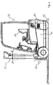
- Fig. 1 shows an industrial truck 10 with a tiltable mast 12 in a view from the side.
- the industrial truck 10 has a drive part 14 and a load part 16 to which the lifting frame 12 belongs.
- the drive part 14 has a lithium-ion battery (not shown), which can be arranged, for example, in the space under the driver's seat 18.
- a built-in charger 20 is shown schematically; in the exemplary embodiment it is positioned above the rear drive wheel 22.
- a charging cable with which the industrial truck 10 can be connected to a conventional 230V socket instead of an external charging cable, it can also be provided that the vehicle is equipped with an internal charging cable which, if necessary, can be pulled out and connected to an external socket.
- An automatic winding device for the cable is preferably also provided for such an internal charging cable.
- Fig. 2 shows the circuit diagram of the built-in charger 20.
- the external voltage U zk is applied to a resonance converter 24.
- the resonance converter 24 has four transistors Sn, S 12 , S 13 and S 14 , which are designed as GaN transistors.
- the switching frequency of the GaN transistors which corresponds to the frequency of the current in the resonance circuit, is also possible in a range of over 100 kHz due to the low switching losses of the GaN transistors.
- the passive components such as the transformer 26 can be made very compact.
- a current doubler with coupled inductances L a , L b is provided on the secondary side.
- the current doubler 28 has two transistors S 21 , S 22 , which are preferably also designed as GaN transistors.
- the battery voltage U Bat is applied to the current doubler.
- the battery voltage is, for example, 24, 40 or 80 V, depending on the design of the industrial truck.
- the presented construction of a built-in charger offers a large number of advantages, especially compared to other built-in chargers. Due to the comparatively low battery voltages, the current flow on the output side in the built-in charger is very high and can well exceed 100 A. If a battery with a battery voltage of 24 V is charged at a Schuko socket with 3.6 kW, for example, currents of 150 A occur. With a three-phase connection (CEE) with 16 amperes and 11 kW, currents of 230 A occur for an industrial truck with a battery voltage of 48 V.
- CEE three-phase connection
- resonant topologies have previously been used in built-in chargers, a standard high-frequency transformer with a full bridge rectifier or a transformer with a center tap is often used.
- the disadvantage of these resonant topologies is a low level of efficiency.
- Full bridge rectifiers show significant switching losses, since the current flows through two diodes.
- Transformers with center tap are complex to design and their secondary direction is permanently energized, which leads to high losses, especially with high currents.
Landscapes
- Engineering & Computer Science (AREA)
- Transportation (AREA)
- Structural Engineering (AREA)
- Power Engineering (AREA)
- Civil Engineering (AREA)
- Life Sciences & Earth Sciences (AREA)
- Geology (AREA)
- Mechanical Engineering (AREA)
- Chemical & Material Sciences (AREA)
- Combustion & Propulsion (AREA)
- Charge And Discharge Circuits For Batteries Or The Like (AREA)
- Dc-Dc Converters (AREA)
Abstract
1. das Einbauladegerät einen Resonanzwandler (24) mit einer Vollbrücke aufweist, deren Transistoren als GaN-Transistoren ausgebildet sind und
2. ein Transformator (26) vorgesehen ist,
3. auf dessen Sekundärseite ein Stromdoppler (28) mit zwei gekoppelten Induktivitäten (La, Lb) vorgesehen ist.
Description
- Die vorliegende Erfindung betrifft ein Flurförderzeug mit einem Einbauladegerät, das über ein Kabel mit einer externen Spannungsquelle verbunden werden kann, um eine an Bord befindliche Batterie zu laden. Bei einer externen Spannungsquelle kann es sich um eine herkömmliche Steckdose handeln.
- Flurförderzeuge werden zunehmend mit Lithium-Ionen-Batterien angetrieben, die für Schnell- und Zwischenladevorgänge beispielsweise mit einem C-Faktor von 1 C geeignet sind. Gerade im Mehrschichtbetrieb der Fahrzeuge sind Schnell- und Zwischenladevorgänge sehr hilfreich, für den kontinuierlichen Betrieb der Fahrzeugflotte.
- Bevorzugt kann ein Flurförderzeug hierbei an eine übliche Steckdose, wie beispielsweise eine Schuko-Steckdose angeschlossen werden, dies macht es erforderlich, dass die Leistungselektronik des Ladegeräts fahrzeugseitig an Bord angeordnet ist. Kritisch für die Verwendung solcher an Bord befindlicher Ladegeräte ist der begrenzte Bauraum im Fahrzeug und die auf Grund der hohen Leistungsdichte abzuführende Wärmemenge.
- Aus
EP 2 781 012 B1 ist eine Gleichrichterschaltung bekannt, die Elemente einer Stromverdopplerschaltung einsetzt, unter anderem für ein induktives Ladesystem. - Aus
CN 201122859 ist eine 24-V Ladegerät bekannt geworden, dass für eine stabile Gleichstromausgangsspannung eine Kompensation für die Restwelligkeit besitzt. - Aus
EP 2 618 449 A2 ist ein System bekannt, mit dem eine Niederspannungsbatterie aus einer Hochspannungsbatterie geladen werden kann. Hierzu wird ein currentdoubler mit gekoppelten Induktivitäten eingesetzt. - Der Erfindung liegt die Aufgabe zu Grunde ein Flurförderzeug mit einem Einbauladegerät bereitzustellen, das bei geringem Bauraum einen hohen Wirkungsgrad besitzt.
- Erfindungsgemäß wird die Aufgabe durch ein Flurförderzeug mit den Merkmalen aus Anspruch 1 gelöst. Vorteilhafte Ausgestaltungen bilden die Gegenstände der Unteransprüche.
- Das erfindungsgemäße Flurförderzeug ist mit einem Einbauladegerät ausgestattet, das über ein Kabel mit einer externen Spannungsquelle verbunden werden kann, um eine an Bord befindliche Batterie des Flurförderzeugs zu laden. Das Einbauladegerät besitzt einen Resonanzwandler mit einer Vollbrücke, deren Transistoren als GaN-Transistoren ausgebildet sind. Ferner ist ein Transformator vorgesehen, auf dessen Sekundärseite ein Stromdoppler mit zwei gekoppelten Induktivitäten vorgesehen ist. Die Verwendung eines Resonanzwandlers ermöglicht einen sehr hohen Wirkungsgrad, da eine resonante LLC Topologie beispielsweise bei 0 V (zero voltage switching ZVS) verlustarm geschaltet werden kann. Des Weiteren erlaubt der Resonanzwandler eine sehr kompakte Bauweise, da die Schaltfrequenz der GaN-Transistoren der Frequenz des Stroms im Resonanzkreis entspricht. Aufgrund der geringen Schaltverluste von GaN-Transistoren kann diese Frequenz sehr hoch, deutlich höher als 100 kHz gewählt werden. Zudem besitzt die Verwendung eines Resonanzwandlers in einem kompakt gebauten Flurförderzeug den Vorteil, dass eine elektromagnetische Störaussendung deutlich reduziert werden kann, wenn im Nulldurchgang geschaltet wird. Hinzu kommt, dass die Realisierung der sekundärseitigen Induktivitäten als gekoppelte Induktivitäten eine deutliche Verbesserung der Ausgangsstromwelligkeit erzielt.
- In einer bevorzugten Weiterbildung des erfindungsgemäßen Flurförderzeugs ist auch der Stromdoppler mit zwei GaN-Transistoren ausgestattet.
- Eine besondere Eigenschaft des erfindungsgemäßen Flurförderzeugs liegt darin, dass die zu ladende Batterie eine Spannung von weniger als 100 V, bevorzugt von weniger als 80 V besitzt. Bei Flurförderzeugen übliche Batteriespannungen sind beispielsweise 24 V, 40 V oder 80 V. Ferner tritt an dem Einbauladegerät ausgangsseitig ein Stromfluss mit einer Stärke von 70 A mehr, bevorzugt können es auch 100 A oder mehr sein, auf. Derartig große Ladeströme sind eine besondere Herausforderung für die Leistungselektronik und erfordern gerade bei einer hohen Leistungsdichte besonders aufeinander abgestimmte Schaltungen. Durch den Einsatz von GaN Transistoren liegt eine höhere Schaltfrequenz als bei konventionellen Silizium-Halbleitern vor, da die Verlustenergien bei einem Schaltvorgang deutlich geringer sind. Durch die Verwendung von gekoppelten Induktivitäten wird bei gleichem Bauvolumen im Vergleich zu diskreten Induktivitäten die Welligkeit des Ausgangsstroms reduziert. In einer Systemauslegung gilt es stets, den bestmöglichen Kompromiss zwischen der Schaltfrequenz der GaN-Transistoren und den Eigenschaften der gekoppelten Induktivitäten zu finden. Die beiden Größen hängen damit direkt zusammen.
- Die Anwendung in Flurförderzeugen ist dadurch gekennzeichnet, dass ausgangsseitig vergleichsweise geringe Spannungen aber hohe Ströme auftreten. Hohe Schaltfrequenzen im Zusammenhang mit hohen Strömen im Transformator führen zu hohen Verlusten im Kernmaterial (Ummagnetisierung). Durch die Verwendung von gekoppelten Induktivitäten auf der Sekundärseite gleichen sich die Ströme durch die beiden Zweige des Current Doublers aus und damit auch die Ströme der beiden Halbwellen im Transformator. Ohne diesen Ausgleich würde es bei der hohen verwendeten Schaltfrequenz, die bei GaN-Halbleitern zum Einsatz kommt, zu einer möglichen thermischen Überbelastung des Transformators kommen.
- In einer bevorzugten Ausgestaltung ist das Einbauladegerät mit einem C-Faktor von mehr als 0,5 C ausgestattet. Der C-Faktor gibt die maximalen Lade- und Entladeströme unter bestimmten Randbedingungen an, die SI-Einheit lautet s-1. Bei einem C-Faktor von beispielsweise 2 C und einer Batteriekapazität von 3 Ah ergibt sich dann ein maximaler Ladestrom von 6 A. Ein C-Faktor von mehr als 0,5 C, beispielsweise 1,0 C erlaubt ein Schnellladen oder eine Zwischenladung von Lithium-Ionen-Batterien. Die GaN-Transistoren und die gekoppelten Induktivitäten wirken zusammen. Für einen OnBoard-Charger in Flurförderzeugen (insbesondere in kleinen Fahrzeugen wie Kommissionierern, Deichselstaplern etc.) ist der zur Verfügung stehende Bauraum stark begrenzt. Zusammen mit den Anforderungen an eine schnelle Ladung von Li-Ionen Batterien mit beispielsweise 1C ergeben sich daraus sehr hohe Anforderungen an die Leistungsdichte. Diese lassen sich nur erfüllen, wenn GaN-Transistoren in Kombination mit gekoppelten Induktivitäten zum Einsatz kommen.
- Insbesondere im Hinblick auf die großen Ladeströme ist es zweckmäßig eine aktive Kühlung für die Leistungselektronik vorzusehen.
- Das erfindungsgemäße Flurförderzeug ist bei dem Anschluss an eine externe Spannungsquelle beispielsweise an eine Wechselspannungsquelle mit beispielsweise 230 V anschließbar. Hierbei handelt es sich bevorzugt um eine herkömmliche Steckdose. Bevorzugt sind die an Bord befindlichen Batterien am Förderzeug Lithium-Ionen- oder andere Feststoffbatterien, die über das Einbauladegerät geladen werden.
- Die vorstehende Erfindung wird nachfolgend an einem Ausführungsbeispiel näher erläutert. Es zeigt:
- Fig.1
- ein erfindungsgemäßes Flurförderzeug mit einem Einbauladegerät und
- Fig. 2
- ein Schaltbild zu dem Einbauladegerät.
-
Fig. 1 zeigt ein Flurförderzeug 10 mit einem neigbaren Hubgerüst 12 in einer Ansicht von der Seite. Das Flurförderzeug 10 besitzt ein Antriebsteil 14 und ein Lastteil 16 zu dem das Hubgerüst 12 gehört. Das Antriebsteil 14 besitzt eine Lithium-Ionen-Batterie (nicht dargestellt), die beispielsweise im Raum unter dem Fahrersitz 18 angeordnet sein kann. Ein Einbauladegerät 20 ist schematisch dargestellt, in dem Ausführungsbeispiel ist es oberhalb des hinteren Antriebsrades 22 positioniert. - Nicht dargestellt in
Fig. 1 ist ein Ladekabel, mit dem das Flurförderzeug 10 mit einer herkömmlichen 230V Steckdose verbunden werden kann. Anstelle eines externen Ladekabels, kann auch vorgesehen sein, dass das Fahrzeug mit einem internen Ladekabel ausgestattet ist, das bei Bedarf herausgezogen und mit einer externen Steckdose verbunden werden kann. Bevorzugt ist für ein solches internes Ladekabel auch eine automatische Aufwickeleinrichtung für das Kabel vorgesehen. -
Fig. 2 zeigt das Schaltbild des Einbauladegeräts 20. In dem Schaltbild liegt die externe Spannung Uzk an einem Resonanzwandler 24 an. Der Resonanzwandler 24 besitzt vier Transistoren Sn, S12, S13 und S14, die als GaN-Transistoren ausgebildet sind. Die Schaltfrequenz der GaN-Transistoren, die der Frequenz des Stromes im Resonanzkreis entspricht ist aufgrund der geringen Schaltverluste der GaN-Transistoren auch in einem Bereich von über 100 kHz möglich. Durch die hohe Schaltfrequenz können die passiven Bauelemente wie beispielsweise der Transformator 26 sehr kompakt gebaut werden. Sekundärseitig ist ein Stromverdoppler mit gekoppelten Induktivitäten La, Lb vorgesehen. Der Stromdoppler 28 besitzt zwei Transistoren S21, S22, die bevorzugt ebenfalls als GaN-Transistoren ausgebildet sind. Ausgangsseitig liegt an dem Stromdoppler die Batteriespannung UBat an. Die Batteriespannung beträgt je nach Ausbildung des Flurförderzeugs beispielsweise 24, 40 oder 80 V. - Der vorgestellte Aufbau eines Einbauladegeräts bietet eine große Reihe von Vorteilen gerade auch gegenüber sonstigen Einbauladegeräten. Durch die vergleichsweise niedrigen Batteriespannungen ist der ausgangsseitige Stromfluss im Einbauladegerät sehr hoch und kann 100 A deutlich übersteigen. Wird eine Batterie mit einer Batteriespannung von 24 V beispielsweise an einer Schuko-Steckdose mit 3,6 kW geladen, so treten Ströme von 150 A auf. Bei einem dreiphasigen Anschluss (CEE) mit 16 Ampere und 11 kW treten für ein Flurförderzeug mit einer Batteriespannung von 48 V Ströme von 230 A auf.
- Soweit bei Einbauladegeräten bisher resonante Topologien eingesetzt werden, kommt häufig ein Standardhochfrequenztransformator mit einem Vollbrückengleichrichter oder ein Transformator mit Mittenabgriff in Frage. Nachteil dieser resonanten Topologien ist ein niedriger Wirkungsgrad. Vollbrückengleichrichter weisen deutliche Schaltverluste auf, da der Strom jeweils durch zwei Dioden fließt. Transformatoren mit Mittenabgriff sind aufwändig zu konstruieren und ihre Sekundärrichtung ist permanent bestromt, was zu hohen Verlusten insbesondere bei hohen Strömen führt.
Claims (8)
- Flurförderzeug mit einem Einbauladegerät, das über ein Kabel mit einer externen Spannungsquelle verbunden werden kann, um eine an Bord befindliche Batterie zu laden, dadurch gekennzeichnet, dass1. das Einbauladegerät einen Resonanzwandler mit einer Vollbrücke aufweist, deren Transistoren als GaN-Transistoren ausgebildet sind und2. ein Transformator vorgesehen ist,3. auf dessen Sekundärseite ein Stromdoppler mit zwei gekoppelten Induktivitäten (La, Lb) vorgesehen ist.
- Flurförderzeug nach Anspruch 1, dadurch gekennzeichnet, dass der Stromdoppler mit zwei GaN-Transistoren ausgestattet ist.
- Flurförderzeug nach Anspruch 1 oder 2, dadurch gekennzeichnet, dass die zu ladende Batterie eine Spannung von weniger als 100 V besitzt, bevorzugt 80 V oder weniger.
- Flurförderzeug nach einem der Ansprüche 1 bis 3, dadurch gekennzeichnet, dass der ausgangsseitige Stromfluss eine Stromstärke von 70A oder mehr, bevorzugt von 100 A oder mehr besitzt.
- Flurförderzeug nach einem der Ansprüche 1 bis 4, dadurch gekennzeichnet, dass das Einbauladegerät einen C-Faktor von mehr als 0,5 C besitzt.
- Flurförderzeug nach einem der Ansprüche 1 bis 5, dadurch gekennzeichnet, dass eine aktive Kühlung für die Leistungselektronik vorgesehen ist.
- Flurförderzeug nach einem der vorausgehenden Ansprüche, dadurch gekennzeichnet, dass ein 230 V Wechselspannungsanschluss als externe Spannungsquelle vorgesehen ist.
- Flurförderzeug nach einem der vorausgehenden Ansprüche, dadurch gekennzeichnet, dass eine Lithium-Ionen oder eine Feststoffbatterie als am Fahrzeug mitgeführte Batterie vorgesehen ist.
Applications Claiming Priority (1)
| Application Number | Priority Date | Filing Date | Title |
|---|---|---|---|
| DE102019122659.7A DE102019122659A1 (de) | 2019-08-22 | 2019-08-22 | Flurförderzeug mit einem Einbauladegerät |
Publications (2)
| Publication Number | Publication Date |
|---|---|
| EP3782953A1 true EP3782953A1 (de) | 2021-02-24 |
| EP3782953B1 EP3782953B1 (de) | 2023-07-26 |
Family
ID=72193295
Family Applications (1)
| Application Number | Title | Priority Date | Filing Date |
|---|---|---|---|
| EP20192092.3A Active EP3782953B1 (de) | 2019-08-22 | 2020-08-21 | Flurförderzeug mit einem einbauladegerät |
Country Status (2)
| Country | Link |
|---|---|
| EP (1) | EP3782953B1 (de) |
| DE (1) | DE102019122659A1 (de) |
Cited By (1)
| Publication number | Priority date | Publication date | Assignee | Title |
|---|---|---|---|---|
| WO2023093216A1 (zh) * | 2021-11-26 | 2023-06-01 | 荣耀终端有限公司 | 开关电路及电子设备 |
Families Citing this family (1)
| Publication number | Priority date | Publication date | Assignee | Title |
|---|---|---|---|---|
| DE102023101359A1 (de) | 2023-01-19 | 2024-07-25 | Jungheinrich Aktiengesellschaft | Ladegerät für ein Flurförderzeug |
Citations (10)
| Publication number | Priority date | Publication date | Assignee | Title |
|---|---|---|---|---|
| EP1657106A1 (de) * | 2004-11-10 | 2006-05-17 | Jungheinrich Aktiengesellschaft | Ladegerät für ein Flurförderzeug |
| CN201122859Y (zh) | 2007-11-26 | 2008-09-24 | 谢步明 | 机车车辆用直流24v充电机 |
| US20110194206A1 (en) * | 2010-02-10 | 2011-08-11 | Hitachi, Ltd. | Power-Supply Unit, Hard-Disk Drive, and Switching Method of the Power-Supply Unit |
| US20120163052A1 (en) * | 2010-12-24 | 2012-06-28 | Fujitsu Limited | Power supply unit and information processor |
| EP2618449A2 (de) | 2011-12-30 | 2013-07-24 | LSIS Co., Ltd. | Vorrichtung zum Laden einer Batterie in einem elektrischen Fahrzeug |
| US20160052410A1 (en) * | 2014-08-19 | 2016-02-25 | General Electric Company | Vehicle propulsion system having an energy storage system and optimized method of controlling operation thereof |
| EP2781012B1 (de) | 2011-11-17 | 2016-07-13 | Qualcomm Incorporated | Systeme, verfahren und vorrichtungen für einen einphasen-gleichrichter mit hohem leistungsfaktor |
| EP3229307A2 (de) * | 2016-04-04 | 2017-10-11 | The Raymond Corporation | Gehäuse für einen energiespeicher und methode zur durchzugskühlung |
| US20180123360A1 (en) * | 2016-10-31 | 2018-05-03 | VoltServer, Inc. | Digital Power Multiport Battery Charging System |
| US20180170207A1 (en) * | 2016-12-20 | 2018-06-21 | Hyundai Motor Company | System and Method for Managing Battery for Vehicle, and Vehicle Thereof |
Family Cites Families (1)
| Publication number | Priority date | Publication date | Assignee | Title |
|---|---|---|---|---|
| DE102016221514A1 (de) * | 2016-11-03 | 2018-05-03 | Audi Ag | Energietechnisches Koppeln eines Hochvoltbordnetzes mit einem Kleinspannungsbordnetz |
-
2019
- 2019-08-22 DE DE102019122659.7A patent/DE102019122659A1/de not_active Withdrawn
-
2020
- 2020-08-21 EP EP20192092.3A patent/EP3782953B1/de active Active
Patent Citations (10)
| Publication number | Priority date | Publication date | Assignee | Title |
|---|---|---|---|---|
| EP1657106A1 (de) * | 2004-11-10 | 2006-05-17 | Jungheinrich Aktiengesellschaft | Ladegerät für ein Flurförderzeug |
| CN201122859Y (zh) | 2007-11-26 | 2008-09-24 | 谢步明 | 机车车辆用直流24v充电机 |
| US20110194206A1 (en) * | 2010-02-10 | 2011-08-11 | Hitachi, Ltd. | Power-Supply Unit, Hard-Disk Drive, and Switching Method of the Power-Supply Unit |
| US20120163052A1 (en) * | 2010-12-24 | 2012-06-28 | Fujitsu Limited | Power supply unit and information processor |
| EP2781012B1 (de) | 2011-11-17 | 2016-07-13 | Qualcomm Incorporated | Systeme, verfahren und vorrichtungen für einen einphasen-gleichrichter mit hohem leistungsfaktor |
| EP2618449A2 (de) | 2011-12-30 | 2013-07-24 | LSIS Co., Ltd. | Vorrichtung zum Laden einer Batterie in einem elektrischen Fahrzeug |
| US20160052410A1 (en) * | 2014-08-19 | 2016-02-25 | General Electric Company | Vehicle propulsion system having an energy storage system and optimized method of controlling operation thereof |
| EP3229307A2 (de) * | 2016-04-04 | 2017-10-11 | The Raymond Corporation | Gehäuse für einen energiespeicher und methode zur durchzugskühlung |
| US20180123360A1 (en) * | 2016-10-31 | 2018-05-03 | VoltServer, Inc. | Digital Power Multiport Battery Charging System |
| US20180170207A1 (en) * | 2016-12-20 | 2018-06-21 | Hyundai Motor Company | System and Method for Managing Battery for Vehicle, and Vehicle Thereof |
Cited By (2)
| Publication number | Priority date | Publication date | Assignee | Title |
|---|---|---|---|---|
| WO2023093216A1 (zh) * | 2021-11-26 | 2023-06-01 | 荣耀终端有限公司 | 开关电路及电子设备 |
| US12549170B2 (en) | 2021-11-26 | 2026-02-10 | Honor Device Co., Ltd. | Switch circuit and electronic device |
Also Published As
| Publication number | Publication date |
|---|---|
| DE102019122659A1 (de) | 2021-02-25 |
| EP3782953B1 (de) | 2023-07-26 |
Similar Documents
| Publication | Publication Date | Title |
|---|---|---|
| DE102011075927B4 (de) | Multifunktionaler stromrichter von gleichspannung zu gleichspannung, von gleichspannung zu wechselspannung und von wechselspannung zu gleichspannung | |
| EP3334022B1 (de) | Stromrichtereinrichtung für ein kraftfahrzeug und kraftfahrzeug | |
| EP2623363B1 (de) | Vorrichtung und Verfahren zum Laden einer Traktionsbatterie eines Elektrofahrzeugs | |
| DE112015001844T5 (de) | Ladevorrichtung für Elektrofahrzeuge | |
| DE102009052680A1 (de) | Ladevorrichtung zum Laden einer Batterie eines Kraftfahrzeugs mit Tiefsetzsteller | |
| EP3005526B1 (de) | Schaltungsanordnung für den primärteil eines systems zur kontaktlosen energieübertragung, sowie übertragerelement | |
| WO2017050549A1 (de) | Fahrzeugseitige leistungsschaltung zur stromversorgung in einem elektrisch angetriebenen fahrzeug | |
| DE102019005621A1 (de) | Bordnetz für ein elektrisch antreibbares Kraftfahrzeug | |
| DE102014118347A1 (de) | Magnetisch koppelnder Induktor und Multiport-Wandler | |
| EP3782953B1 (de) | Flurförderzeug mit einem einbauladegerät | |
| WO2018041493A1 (de) | Bidirektionaler bordnetzumrichter und verfahren zu dessen betrieb | |
| DE4426017C2 (de) | Stromversorgungsgerät, insbesondere Batterie-Ladegerät für Elektrofahrzeuge oder dergleichen | |
| DE102019212930B3 (de) | Fahrzeugbordnetz und Verfahren zum Betreiben eines Fahrzeugbordnetzes | |
| DE102012220371A1 (de) | Vorrichtung zum Laden eines elektrischen Energiespeichers aus einer Wechselspannungsquelle | |
| EP3783769A1 (de) | Ladegerät für ein flurförderzeug | |
| EP2822166B1 (de) | Eintakt-Durchflusswandler mit sekundärseitiger Snubberschaltung | |
| DE102024205527B3 (de) | Elektrisches Traktionsnetz für ein Kraftfahrzeug und Verfahren zum Betreiben eines solchen in einem Fahr- und einem Lademodus | |
| DE112015000884T5 (de) | Induktive Ladevorrichtung | |
| DE102015101087A1 (de) | Schaltungsanordnung | |
| DE102019005381A1 (de) | Elektrische Schaltung zum Laden eines elektrischen Energiespeichers für ein zumindest teilweise elektrisch betreibbares Kraftfahrzeug sowie Verfahren | |
| DE102023201656A1 (de) | Ladevorrichtung sowie elektrisches Antriebs- und Ladesystem für ein Elektrofahrzeug | |
| DE102016009665A1 (de) | Verbindungseinrichtung für ein Kraftfahrzeug sowie Verfahren zum Laden eines kraftfahrzeugseitigen Energiespeichers | |
| DE102024002035B3 (de) | Elektrisches Antriebssystem und Verfahren zum Laden | |
| DE102024003960B3 (de) | Elektrisches Hochvoltsystem | |
| EP3874575B1 (de) | Vorrichtung zur energieverteilung |
Legal Events
| Date | Code | Title | Description |
|---|---|---|---|
| PUAI | Public reference made under article 153(3) epc to a published international application that has entered the european phase |
Free format text: ORIGINAL CODE: 0009012 |
|
| STAA | Information on the status of an ep patent application or granted ep patent |
Free format text: STATUS: THE APPLICATION HAS BEEN PUBLISHED |
|
| AK | Designated contracting states |
Kind code of ref document: A1 Designated state(s): AL AT BE BG CH CY CZ DE DK EE ES FI FR GB GR HR HU IE IS IT LI LT LU LV MC MK MT NL NO PL PT RO RS SE SI SK SM TR |
|
| AX | Request for extension of the european patent |
Extension state: BA ME |
|
| STAA | Information on the status of an ep patent application or granted ep patent |
Free format text: STATUS: REQUEST FOR EXAMINATION WAS MADE |
|
| 17P | Request for examination filed |
Effective date: 20210823 |
|
| RBV | Designated contracting states (corrected) |
Designated state(s): AL AT BE BG CH CY CZ DE DK EE ES FI FR GB GR HR HU IE IS IT LI LT LU LV MC MK MT NL NO PL PT RO RS SE SI SK SM TR |
|
| GRAP | Despatch of communication of intention to grant a patent |
Free format text: ORIGINAL CODE: EPIDOSNIGR1 |
|
| STAA | Information on the status of an ep patent application or granted ep patent |
Free format text: STATUS: GRANT OF PATENT IS INTENDED |
|
| RIC1 | Information provided on ipc code assigned before grant |
Ipc: H02M 3/00 20060101ALI20230123BHEP Ipc: H02M 3/335 20060101ALI20230123BHEP Ipc: B66F 9/24 20060101ALI20230123BHEP Ipc: B66F 9/075 20060101AFI20230123BHEP |
|
| INTG | Intention to grant announced |
Effective date: 20230216 |
|
| GRAS | Grant fee paid |
Free format text: ORIGINAL CODE: EPIDOSNIGR3 |
|
| GRAA | (expected) grant |
Free format text: ORIGINAL CODE: 0009210 |
|
| STAA | Information on the status of an ep patent application or granted ep patent |
Free format text: STATUS: THE PATENT HAS BEEN GRANTED |
|
| AK | Designated contracting states |
Kind code of ref document: B1 Designated state(s): AL AT BE BG CH CY CZ DE DK EE ES FI FR GB GR HR HU IE IS IT LI LT LU LV MC MK MT NL NO PL PT RO RS SE SI SK SM TR |
|
| REG | Reference to a national code |
Ref country code: CH Ref legal event code: EP |
|
| P01 | Opt-out of the competence of the unified patent court (upc) registered |
Effective date: 20230628 |
|
| REG | Reference to a national code |
Ref country code: DE Ref legal event code: R096 Ref document number: 502020004347 Country of ref document: DE |
|
| REG | Reference to a national code |
Ref country code: IE Ref legal event code: FG4D Free format text: LANGUAGE OF EP DOCUMENT: GERMAN |
|
| REG | Reference to a national code |
Ref country code: SE Ref legal event code: TRGR |
|
| REG | Reference to a national code |
Ref country code: LT Ref legal event code: MG9D |
|
| REG | Reference to a national code |
Ref country code: NL Ref legal event code: MP Effective date: 20230726 |
|
| PG25 | Lapsed in a contracting state [announced via postgrant information from national office to epo] |
Ref country code: NL Free format text: LAPSE BECAUSE OF FAILURE TO SUBMIT A TRANSLATION OF THE DESCRIPTION OR TO PAY THE FEE WITHIN THE PRESCRIBED TIME-LIMIT Effective date: 20230726 |
|
| PG25 | Lapsed in a contracting state [announced via postgrant information from national office to epo] |
Ref country code: GR Free format text: LAPSE BECAUSE OF FAILURE TO SUBMIT A TRANSLATION OF THE DESCRIPTION OR TO PAY THE FEE WITHIN THE PRESCRIBED TIME-LIMIT Effective date: 20231027 |
|
| PG25 | Lapsed in a contracting state [announced via postgrant information from national office to epo] |
Ref country code: IS Free format text: LAPSE BECAUSE OF FAILURE TO SUBMIT A TRANSLATION OF THE DESCRIPTION OR TO PAY THE FEE WITHIN THE PRESCRIBED TIME-LIMIT Effective date: 20231126 |
|
| PG25 | Lapsed in a contracting state [announced via postgrant information from national office to epo] |
Ref country code: RS Free format text: LAPSE BECAUSE OF FAILURE TO SUBMIT A TRANSLATION OF THE DESCRIPTION OR TO PAY THE FEE WITHIN THE PRESCRIBED TIME-LIMIT Effective date: 20230726 Ref country code: PT Free format text: LAPSE BECAUSE OF FAILURE TO SUBMIT A TRANSLATION OF THE DESCRIPTION OR TO PAY THE FEE WITHIN THE PRESCRIBED TIME-LIMIT Effective date: 20231127 Ref country code: NO Free format text: LAPSE BECAUSE OF FAILURE TO SUBMIT A TRANSLATION OF THE DESCRIPTION OR TO PAY THE FEE WITHIN THE PRESCRIBED TIME-LIMIT Effective date: 20231026 Ref country code: LV Free format text: LAPSE BECAUSE OF FAILURE TO SUBMIT A TRANSLATION OF THE DESCRIPTION OR TO PAY THE FEE WITHIN THE PRESCRIBED TIME-LIMIT Effective date: 20230726 Ref country code: LT Free format text: LAPSE BECAUSE OF FAILURE TO SUBMIT A TRANSLATION OF THE DESCRIPTION OR TO PAY THE FEE WITHIN THE PRESCRIBED TIME-LIMIT Effective date: 20230726 Ref country code: IS Free format text: LAPSE BECAUSE OF FAILURE TO SUBMIT A TRANSLATION OF THE DESCRIPTION OR TO PAY THE FEE WITHIN THE PRESCRIBED TIME-LIMIT Effective date: 20231126 Ref country code: HR Free format text: LAPSE BECAUSE OF FAILURE TO SUBMIT A TRANSLATION OF THE DESCRIPTION OR TO PAY THE FEE WITHIN THE PRESCRIBED TIME-LIMIT Effective date: 20230726 Ref country code: GR Free format text: LAPSE BECAUSE OF FAILURE TO SUBMIT A TRANSLATION OF THE DESCRIPTION OR TO PAY THE FEE WITHIN THE PRESCRIBED TIME-LIMIT Effective date: 20231027 Ref country code: FI Free format text: LAPSE BECAUSE OF FAILURE TO SUBMIT A TRANSLATION OF THE DESCRIPTION OR TO PAY THE FEE WITHIN THE PRESCRIBED TIME-LIMIT Effective date: 20230726 |
|
| PG25 | Lapsed in a contracting state [announced via postgrant information from national office to epo] |
Ref country code: PL Free format text: LAPSE BECAUSE OF FAILURE TO SUBMIT A TRANSLATION OF THE DESCRIPTION OR TO PAY THE FEE WITHIN THE PRESCRIBED TIME-LIMIT Effective date: 20230726 |
|
| REG | Reference to a national code |
Ref country code: CH Ref legal event code: PL |
|
| PG25 | Lapsed in a contracting state [announced via postgrant information from national office to epo] |
Ref country code: LU Free format text: LAPSE BECAUSE OF NON-PAYMENT OF DUE FEES Effective date: 20230821 |
|
| PG25 | Lapsed in a contracting state [announced via postgrant information from national office to epo] |
Ref country code: ES Free format text: LAPSE BECAUSE OF FAILURE TO SUBMIT A TRANSLATION OF THE DESCRIPTION OR TO PAY THE FEE WITHIN THE PRESCRIBED TIME-LIMIT Effective date: 20230726 |
|
| REG | Reference to a national code |
Ref country code: DE Ref legal event code: R097 Ref document number: 502020004347 Country of ref document: DE |
|
| PG25 | Lapsed in a contracting state [announced via postgrant information from national office to epo] |
Ref country code: SM Free format text: LAPSE BECAUSE OF FAILURE TO SUBMIT A TRANSLATION OF THE DESCRIPTION OR TO PAY THE FEE WITHIN THE PRESCRIBED TIME-LIMIT Effective date: 20230726 Ref country code: RO Free format text: LAPSE BECAUSE OF FAILURE TO SUBMIT A TRANSLATION OF THE DESCRIPTION OR TO PAY THE FEE WITHIN THE PRESCRIBED TIME-LIMIT Effective date: 20230726 Ref country code: LU Free format text: LAPSE BECAUSE OF NON-PAYMENT OF DUE FEES Effective date: 20230821 Ref country code: ES Free format text: LAPSE BECAUSE OF FAILURE TO SUBMIT A TRANSLATION OF THE DESCRIPTION OR TO PAY THE FEE WITHIN THE PRESCRIBED TIME-LIMIT Effective date: 20230726 Ref country code: EE Free format text: LAPSE BECAUSE OF FAILURE TO SUBMIT A TRANSLATION OF THE DESCRIPTION OR TO PAY THE FEE WITHIN THE PRESCRIBED TIME-LIMIT Effective date: 20230726 Ref country code: DK Free format text: LAPSE BECAUSE OF FAILURE TO SUBMIT A TRANSLATION OF THE DESCRIPTION OR TO PAY THE FEE WITHIN THE PRESCRIBED TIME-LIMIT Effective date: 20230726 Ref country code: CZ Free format text: LAPSE BECAUSE OF FAILURE TO SUBMIT A TRANSLATION OF THE DESCRIPTION OR TO PAY THE FEE WITHIN THE PRESCRIBED TIME-LIMIT Effective date: 20230726 Ref country code: SK Free format text: LAPSE BECAUSE OF FAILURE TO SUBMIT A TRANSLATION OF THE DESCRIPTION OR TO PAY THE FEE WITHIN THE PRESCRIBED TIME-LIMIT Effective date: 20230726 Ref country code: MC Free format text: LAPSE BECAUSE OF FAILURE TO SUBMIT A TRANSLATION OF THE DESCRIPTION OR TO PAY THE FEE WITHIN THE PRESCRIBED TIME-LIMIT Effective date: 20230726 Ref country code: CH Free format text: LAPSE BECAUSE OF NON-PAYMENT OF DUE FEES Effective date: 20230831 |
|
| REG | Reference to a national code |
Ref country code: BE Ref legal event code: MM Effective date: 20230831 |
|
| REG | Reference to a national code |
Ref country code: IE Ref legal event code: MM4A |
|
| PG25 | Lapsed in a contracting state [announced via postgrant information from national office to epo] |
Ref country code: IT Free format text: LAPSE BECAUSE OF FAILURE TO SUBMIT A TRANSLATION OF THE DESCRIPTION OR TO PAY THE FEE WITHIN THE PRESCRIBED TIME-LIMIT Effective date: 20230726 |
|
| PLBE | No opposition filed within time limit |
Free format text: ORIGINAL CODE: 0009261 |
|
| STAA | Information on the status of an ep patent application or granted ep patent |
Free format text: STATUS: NO OPPOSITION FILED WITHIN TIME LIMIT |
|
| 26N | No opposition filed |
Effective date: 20240429 |
|
| PG25 | Lapsed in a contracting state [announced via postgrant information from national office to epo] |
Ref country code: IE Free format text: LAPSE BECAUSE OF NON-PAYMENT OF DUE FEES Effective date: 20230821 |
|
| PG25 | Lapsed in a contracting state [announced via postgrant information from national office to epo] |
Ref country code: IE Free format text: LAPSE BECAUSE OF NON-PAYMENT OF DUE FEES Effective date: 20230821 Ref country code: SI Free format text: LAPSE BECAUSE OF FAILURE TO SUBMIT A TRANSLATION OF THE DESCRIPTION OR TO PAY THE FEE WITHIN THE PRESCRIBED TIME-LIMIT Effective date: 20230726 |
|
| PG25 | Lapsed in a contracting state [announced via postgrant information from national office to epo] |
Ref country code: BE Free format text: LAPSE BECAUSE OF NON-PAYMENT OF DUE FEES Effective date: 20230831 |
|
| PG25 | Lapsed in a contracting state [announced via postgrant information from national office to epo] |
Ref country code: BG Free format text: LAPSE BECAUSE OF FAILURE TO SUBMIT A TRANSLATION OF THE DESCRIPTION OR TO PAY THE FEE WITHIN THE PRESCRIBED TIME-LIMIT Effective date: 20230726 |
|
| PG25 | Lapsed in a contracting state [announced via postgrant information from national office to epo] |
Ref country code: BG Free format text: LAPSE BECAUSE OF FAILURE TO SUBMIT A TRANSLATION OF THE DESCRIPTION OR TO PAY THE FEE WITHIN THE PRESCRIBED TIME-LIMIT Effective date: 20230726 |
|
| GBPC | Gb: european patent ceased through non-payment of renewal fee |
Effective date: 20240821 |
|
| PG25 | Lapsed in a contracting state [announced via postgrant information from national office to epo] |
Ref country code: GB Free format text: LAPSE BECAUSE OF NON-PAYMENT OF DUE FEES Effective date: 20240821 |
|
| PG25 | Lapsed in a contracting state [announced via postgrant information from national office to epo] |
Ref country code: CY Free format text: LAPSE BECAUSE OF FAILURE TO SUBMIT A TRANSLATION OF THE DESCRIPTION OR TO PAY THE FEE WITHIN THE PRESCRIBED TIME-LIMIT; INVALID AB INITIO Effective date: 20200821 |
|
| PG25 | Lapsed in a contracting state [announced via postgrant information from national office to epo] |
Ref country code: HU Free format text: LAPSE BECAUSE OF FAILURE TO SUBMIT A TRANSLATION OF THE DESCRIPTION OR TO PAY THE FEE WITHIN THE PRESCRIBED TIME-LIMIT; INVALID AB INITIO Effective date: 20200821 |
|
| PGFP | Annual fee paid to national office [announced via postgrant information from national office to epo] |
Ref country code: DE Payment date: 20250819 Year of fee payment: 6 |
|
| PGFP | Annual fee paid to national office [announced via postgrant information from national office to epo] |
Ref country code: AT Payment date: 20251020 Year of fee payment: 5 Ref country code: FR Payment date: 20250821 Year of fee payment: 6 |
|
| PGFP | Annual fee paid to national office [announced via postgrant information from national office to epo] |
Ref country code: SE Payment date: 20250821 Year of fee payment: 6 |
|
| PG25 | Lapsed in a contracting state [announced via postgrant information from national office to epo] |
Ref country code: TR Free format text: LAPSE BECAUSE OF FAILURE TO SUBMIT A TRANSLATION OF THE DESCRIPTION OR TO PAY THE FEE WITHIN THE PRESCRIBED TIME-LIMIT Effective date: 20230726 |