EP3782945A1 - Guide rail bracket assembly - Google Patents
Guide rail bracket assembly Download PDFInfo
- Publication number
- EP3782945A1 EP3782945A1 EP19315101.6A EP19315101A EP3782945A1 EP 3782945 A1 EP3782945 A1 EP 3782945A1 EP 19315101 A EP19315101 A EP 19315101A EP 3782945 A1 EP3782945 A1 EP 3782945A1
- Authority
- EP
- European Patent Office
- Prior art keywords
- guide rail
- bracket
- interface
- attached
- plate
- Prior art date
- Legal status (The legal status is an assumption and is not a legal conclusion. Google has not performed a legal analysis and makes no representation as to the accuracy of the status listed.)
- Granted
Links
- 238000000034 method Methods 0.000 claims description 5
- 238000009434 installation Methods 0.000 description 5
- 229910000831 Steel Inorganic materials 0.000 description 2
- 238000011065 in-situ storage Methods 0.000 description 2
- 239000002184 metal Substances 0.000 description 2
- 239000010959 steel Substances 0.000 description 2
- 101100325961 Arabidopsis thaliana BHLH79 gene Proteins 0.000 description 1
- 238000000429 assembly Methods 0.000 description 1
- 230000000712 assembly Effects 0.000 description 1
- 230000008602 contraction Effects 0.000 description 1
- 238000012986 modification Methods 0.000 description 1
- 230000004048 modification Effects 0.000 description 1
- 239000000725 suspension Substances 0.000 description 1
Images


Classifications
-
- B—PERFORMING OPERATIONS; TRANSPORTING
- B66—HOISTING; LIFTING; HAULING
- B66B—ELEVATORS; ESCALATORS OR MOVING WALKWAYS
- B66B7/00—Other common features of elevators
- B66B7/02—Guideways; Guides
- B66B7/04—Riding means, e.g. Shoes, Rollers, between car and guiding means, e.g. rails, ropes
-
- B—PERFORMING OPERATIONS; TRANSPORTING
- B66—HOISTING; LIFTING; HAULING
- B66B—ELEVATORS; ESCALATORS OR MOVING WALKWAYS
- B66B11/00—Main component parts of lifts in, or associated with, buildings or other structures
- B66B11/0005—Constructional features of hoistways
-
- B—PERFORMING OPERATIONS; TRANSPORTING
- B66—HOISTING; LIFTING; HAULING
- B66B—ELEVATORS; ESCALATORS OR MOVING WALKWAYS
- B66B7/00—Other common features of elevators
- B66B7/02—Guideways; Guides
- B66B7/023—Mounting means therefor
- B66B7/024—Lateral supports
-
- B—PERFORMING OPERATIONS; TRANSPORTING
- B66—HOISTING; LIFTING; HAULING
- B66B—ELEVATORS; ESCALATORS OR MOVING WALKWAYS
- B66B7/00—Other common features of elevators
- B66B7/02—Guideways; Guides
- B66B7/023—Mounting means therefor
- B66B7/025—End supports, i.e. at top or bottom
-
- B—PERFORMING OPERATIONS; TRANSPORTING
- B66—HOISTING; LIFTING; HAULING
- B66B—ELEVATORS; ESCALATORS OR MOVING WALKWAYS
- B66B7/00—Other common features of elevators
- B66B7/02—Guideways; Guides
- B66B7/023—Mounting means therefor
- B66B7/026—Interconnections
Definitions
- the present disclosure relates generally to the field of elevator systems, and more particularly to assemblies and methods for guide rail installation in elevator systems.
- the car and counterweight shall each be guided by at least two rigid steel guide rails when a safety gear is employed to stop the car and counterweight in the event of overspeeding or breaking of the suspension.
- the two counterweight guide rails may be connected to one of the car guide rails by a guide rail bracket.
- the guide rail bracket helps to maintain a desired spacing between the guide rails.
- the guide rails and vertical distance between guide rail brackets in an elevator system are chosen so as to ensure the guide rails can withstand the loads and forces imposed on them.
- guide rails having a standard length (e.g. 2.5 or 5 m) are installed. Depending on the height of the hoistway, multiple guide rails are usually connected end-to-end to achieve a desired overall height. Connecting plates known as "fishplates" are commonly bolted to adjacent guide rails to join the guide rails vertically together.
- guide rail bracket assembly for connecting a car guide rail to a pair of left and right counterweight guide rails in an elevator system, the guide rail bracket assembly comprising:
- At least one interface bracket has an integrated fishplate function provided by the connecting plate.
- each of the first, second and third interface brackets forms a connecting plate for vertically connecting together adjacent guide rails.
- the connecting plate comprises at least four openings, each opening arranged to receive a through fastener for direct attachment of the left counterweight guide rail, right counterweight guide rail or car guide rail to its respective interface bracket.
- two openings may receive a through fastener for attachment of a lower guide rail and two openings may receive a through fastener for attachment of a lower guide rail, the upper and lower guide rails being adjacent guide rails vertically connected together by the connecting plate.
- the connecting plate comprises a row of at least four openings arranged to receive a respective through fastener.
- the connecting plate comprises two rows of at least four openings arranged to receive a respective through fastener.
- the guide rail bracket assembly may optionally further comprise through fasteners for the connecting plates. Appropriate through fasteners may, for example, consist of screws, bolts or other known attachment means.
- the first, second and third interface brackets may be suitably shaped to interface with a corresponding guide rail while also providing an integrated fishplate function.
- the first and second interface brackets are L-shaped, comprising a first plate arranged to face the guide rail bracket and a second plate, substantially orthogonal to the first plate, the second plate forming the connecting plate and arranged to face a base of the left or right counterweight guide rail.
- the first and second interface brackets further comprise a third plate, substantially orthogonal to the first plate and the second plate, the third plate extending away from the second plate that forms the connecting plate.
- the third plate comprises one or more openings for through fasteners to attach the first/second interface bracket to a support bracket.
- the guide rail bracket assembly may further comprise a support bracket configured to fixedly mount the guide rail bracket to a wall.
- a support bracket configured to fixedly mount the guide rail bracket to a wall.
- the support bracket comprises a first support bracket attached to the first interface bracket and a second support bracket attached to the second interface bracket.
- the third interface bracket is U-shaped, comprising a base plate that forms the connecting plate and is arranged to face the guide rail bracket, and first and second side flanges on opposed sides of the base plate that space the base plate away from the guide rail bracket.
- the base plate faces the guide rail bracket as part of a compact layout but, as the base plate forms the connecting plate, there must be space provided to be able to fasten the base plate to adjacent car guide rails.
- the side flanges ensure adequate space for through fasteners by spacing the base plate away from the guide rail bracket.
- first and second side flanges extend away from the base plate and terminate in first and second fastening plates arranged to be fastened to the guide rail bracket.
- the base plate fastens to the car guide rails and the fastening plates fasten to the guide rail bracket, meaning that there are different plates for different sets of through fasteners. This helps to spread loads applied to the interface bracket and assists with ease of installation.
- a guide rail assembly comprising a guide rail bracket assembly according to any of the examples above, a left counterweight guide rail attached to the first interface bracket, a right counterweight guide rail attached to second interface bracket, and a car guide rail attached to the third interface bracket, wherein the first, second and third interface brackets are attached to the guide rail bracket.
- At least one of the left counterweight guide rail, right counterweight guide rail and car guide rail is directly attached to its respective interface bracket by a through fastener. This means that intervening clamps or other fastening arrangements may not be required, so there are fewer components required to fasten the guide rails to the guide rail bracket.
- Such a guide rail assembly may have more than one physical state, e.g. one state designed for ease of transportation and another state used for installation.
- the guide rail assembly has a pre-assembled state, wherein the first, second and third interface brackets are attached to the guide rail bracket and to the guide rails such that the guide rails run substantially parallel to the guide rail bracket.
- This pre-assembled state is very compact and can make transportation easier and/or more cost effective.
- the guide rail assembly has an assembled state, wherein the first, second and third interface brackets are attached to the guide rail bracket and to the guide rails such that the guide rails run substantially perpendicular to the guide rail bracket.
- This assembled state corresponds to the guide rail assembly in situ (e.g. in a hoistway) when installing an elevator system.
- the guide rail assembly comprises: adjacent first and second left counterweight guide rails attached to the first interface bracket so as to be vertically connected together; and/or adjacent first and second right counterweight guide rails are attached to the second interface bracket so as to be vertically connected together; and/or adjacent first and second car guide rails are attached to the third interface bracket so as to be vertically connected together.
- vertically adjacent guide rails may be touching end-to-end or the connecting plate may provide a gap between vertically adjacent guide rails e.g. allowing for building settling and thermal expansion/contraction, without causing buckling of the guide rail.
- the connecting plate may be as described in US 2018/009633 , the contents of which are hereby incorporated by reference.
- the method comprises using through fasteners to directly attach and/or further attach one or more of the left counterweight guide rail, right counterweight guide rail or car guide rail to its respective interface bracket.
- providing the guide rail assembly in a pre-assembled state may optionally include hoisting the guide rail assembly to a desired vertical position before assembling the guide rail bracket to horizontally connect the car guide rail to the left and right counterweight guide rails.
- a guide rail assembly 1 comprises a guide rail bracket 2 horizontally connecting a car guide rail 4 to a pair of left and right counterweight guide rails 6, 8.
- the guide rail bracket 2 is attached to the car guide rail 4 by a clamping bracket 14.
- the clamping bracket 14 includes a shim 15 and a pair of clamps 17a, 17b, each attached to the shim 15 by a screw.
- the shim 15 has two rows of openings for through fasteners 16 with two through fasteners 16 in each row to fasten the clamping bracket 14 to the guide rail bracket 2.
- the car guide rail 4 is restrained between the clamps 17a, 17b, as seen in Figure 1b , i.e. held back against the shim 15.by being pinched between the clamps 17a, 17b.
- the guide rail bracket 2 is attached to the left counterweight guide rail 6 by an interface bracket 10a and to the right counterweight guide rail 8 by a mirror image interface bracket 10b.
- Each interface bracket 10a, 10b has only two openings receiving through fasteners 12 that attach the interface bracket 10a, 10b to a pair of clamps (not seen) that pinch the base of the corresponding counterweight guide rail 6, 8 (in a similar manner to the clamps 17a, 17b described above).
- Figure 1b shows a fishplate 20a vertically connecting together adjacent left counterweight guide rails 6, another fishplate 20b vertically connecting together adjacent car guide rails 4, and another fishplate 20c vertically connecting together adjacent right counterweight guide rails 8.
- Figure 1b shows a fishplate 20a vertically connecting together adjacent left counterweight guide rails 6, another fishplate 20b vertically connecting together adjacent car guide rails 4, and another fishplate 20c vertically connecting together adjacent right counterweight guide rails 8.
- a guide rail assembly 100 comprises a guide rail bracket 102 horizontally connecting a car guide rail 104 to a pair of left and right counterweight guide rails 106, 108.
- a first end portion 103 of the guide rail bracket 102 is attached to the left counterweight guide rail 106 by a first interface bracket 110a and a second end portion 105 of the guide rail bracket 102 is attached to the right counterweight guide rail 108 by a mirror image second interface bracket 110b.
- An intermediate portion 107 of the guide rail bracket 102 is attached to the car guide rail 104 by a third interface bracket 114.
- each interface bracket 110a, 110b, 114 has two rows of four openings 113 receiving through fasteners 112 that attach the interface bracket 110a, 110b, 114 directly to the base of the corresponding guide rail 104, 106, 108.
- the third interface bracket 114 two openings in each row receive through fasteners 112 for a first car guide rail 104 while the other two openings 113 in each row can receive through fasteners for a second adjacent car guide rail (not shown).
- each of the first, second and third interface brackets 110a, 110b, 114 forms a connecting plate for vertically connecting together adjacent guide rails. This is seen in Figure 4 , described further below.
- the third interface bracket 114 is U-shaped, comprising a base plate 130 that forms the connecting plate and is arranged to face the guide rail bracket 102, and first and second side flanges 132a, 132b on opposed sides of the base plate 130 that space the base plate 130 away from the guide rail bracket 102.
- the first and second side flanges 132a, 132b extend away from the base plate 130 and terminate in first and second fastening plates 134a, 134b arranged to be fastened to the guide rail bracket 102.
- first and second interface brackets 110a, 110b are modified in shape in order to interface with the left and right counterweight guide rails 106, 108 while also integrating a fishplate function.
- the first and second interface brackets 110a, 110b are L-shaped, comprising a first plate 140a, 140b arranged to face the guide rail bracket 102 and a second plate 142a, 142b, substantially orthogonal to the first plate 140a, 140b, that forms the connecting plate and is arranged to face a base of the left or right counterweight guide rail 106, 108.
- the first and second interface brackets 110a, 110b further comprise a third plate 144a, 144b, substantially orthogonal to the first plate 140a, 140b and the second plate 142a, 142b.
- the third plate 144a, 144b extends away from the second plate 142a, 142b that forms the connecting plate.
- the L-shaped first and second interface brackets 110a, 110b are single metal parts with a bend formed between the first plate 140a, 140b and the second plate 142a, 142b, and another bend formed between the second plate 142a, 142b and the third plate 144a, 144b.
- the third plate 144b comprises a pair of openings for through fasteners 146 to attach the interface bracket 110b to a support bracket 148b.
- Each support bracket for example the support bracket 148b seen in Figure 2 , is a foot configured to fixedly mount the guide rail bracket 102 to a wall, e.g. the wall of a hoistway or building.
- Such support brackets are provided at both ends of the guide rail bracket 102.
- the first, second and third interface brackets 110a, 110b, 114 are attached to the guide rail bracket 102 and to the guide rails 104, 106, 108 such that the guide rails 104, 106, 108 run substantially parallel to the guide rail bracket 102.
- Figure 3b shows how this is achieved by attaching each of the interface brackets 110a, 110b, 114 to the guide rail bracket 102 by a single through fastener 112.
- the through fasteners 112 may be loosely attached so that the guide rails 104, 106, 108 can be rotated parallel to the guide rail bracket 102 once the guide rail assembly 100 is in situ.
- This pre-assembled state is compact for ease of transportation.
- the guide rail assembly 100 in this pre-assembled state may be hoisted more easily to a desired vertical position (e.g. in a hoistway) ready for installation.
- the first, second and third interface brackets 110a, 110b, 114 are attached to the guide rail bracket 102 and to the guide rails 104, 106, 108 such that the guide rails 104, 106, 108 run substantially perpendicular to the guide rail bracket 102.
- the guide rails 104, 106, 108 are rotated relative to the guide rail bracket 102, for example by loosening the through fasteners 112 seen in Fig. 3b and then re-tightening the through fasteners 112 once the guide rails 104, 106, 108 are perpendicular to the guide rail bracket 102.
- first and second left counterweight guide rails 106 are attached to the first interface bracket 110a so as to be vertically connected together
- adjacent first and second right counterweight guide rails 108 are attached to the second interface bracket 110b so as to be vertically connected together
- adjacent first and second car guide rails 104 are attached to the third interface bracket 114 so as to be vertically connected together. No additional fishplates are required.
- the guide rails disclosed herein have been described, by way of example, as standard T-profile guide rails i.e. wherein the guide rail includes a base and a blade extending therefrom. However, it will be appreciated that the present disclosure is not limited to T-profile guide rails and may be applied to guide rails of any profile.
- the guide rails may be monolithic, e.g. rigid steel guide rails, or formed of metal sheet, or made in any other suitable way as known to the skilled person.
Abstract
Description
- The present disclosure relates generally to the field of elevator systems, and more particularly to assemblies and methods for guide rail installation in elevator systems.
- Current elevator systems use guide rails to provide a track upon which the elevator car and/or counterweight may travel. According to safety standards such as EN81, the car and counterweight shall each be guided by at least two rigid steel guide rails when a safety gear is employed to stop the car and counterweight in the event of overspeeding or breaking of the suspension. Depending on the layout of the elevator system, the two counterweight guide rails may be connected to one of the car guide rails by a guide rail bracket. The guide rail bracket helps to maintain a desired spacing between the guide rails. The guide rails and vertical distance between guide rail brackets in an elevator system are chosen so as to ensure the guide rails can withstand the loads and forces imposed on them.
- In a typical elevator system, guide rails having a standard length (e.g. 2.5 or 5 m) are installed. Depending on the height of the hoistway, multiple guide rails are usually connected end-to-end to achieve a desired overall height. Connecting plates known as "fishplates" are commonly bolted to adjacent guide rails to join the guide rails vertically together.
- It will therefore be appreciated that there are multiple components to be handled and fixed together when installing the guide rails for an elevator system. It would be desirable to reduce the number of components involved when installing an elevator system.
- According to the present disclosure, there is provided guide rail bracket assembly for connecting a car guide rail to a pair of left and right counterweight guide rails in an elevator system, the guide rail bracket assembly comprising:
- a guide rail bracket for horizontally connecting the car guide rail to the pair of left and right counterweight guide rails, the guide rail bracket comprising a first end portion for attachment to the left counterweight guide rail, a second end portion for attachment to the right counterweight guide rail, and an intermediate portion for attachment to the car guide rail;
- a first interface bracket for attaching the first end portion to the left counterweight guide rail, a second interface bracket for attaching the second end portion to the right counterweight guide rail, and a third interface bracket for attaching the intermediate portion to the car guide rail;
- wherein at least one of the first, second and third interface brackets forms a connecting plate for vertically connecting together adjacent guide rails.
- In other words, at least one interface bracket has an integrated fishplate function provided by the connecting plate. This means that a cost reduction may be achieved by employing such a guide rail bracket assembly when installing adjacent guide rails for an elevator system, especially for mid- and high-rise buildings (and associated hoistways), as fewer components are required when installing the guide rails in the hoistway.
- In at least some examples, two or three of the interface brackets each provides such an integrated fishplate function. In at least some examples, each of the first, second and third interface brackets forms a connecting plate for vertically connecting together adjacent guide rails.
- In at least some examples, in addition or alternatively, the connecting plate comprises at least four openings, each opening arranged to receive a through fastener for direct attachment of the left counterweight guide rail, right counterweight guide rail or car guide rail to its respective interface bracket. For example, two openings may receive a through fastener for attachment of a lower guide rail and two openings may receive a through fastener for attachment of a lower guide rail, the upper and lower guide rails being adjacent guide rails vertically connected together by the connecting plate.
- In at least some examples, in addition or alternatively, the connecting plate comprises a row of at least four openings arranged to receive a respective through fastener. This enables the interface bracket to be fixedly attached to the base of a corresponding guide rail by two through fasteners in a row, for safety reasons. Preferably the connecting plate comprises two rows of at least four openings arranged to receive a respective through fastener. This enables the interface bracket to be fixedly attached to the base of a corresponding guide rail by two through fasteners in a row, on either side of the blade. The guide rail bracket assembly may optionally further comprise through fasteners for the connecting plates. Appropriate through fasteners may, for example, consist of screws, bolts or other known attachment means.
- The first, second and third interface brackets may be suitably shaped to interface with a corresponding guide rail while also providing an integrated fishplate function.
- In at least some examples, in addition or alternatively, the first and second interface brackets are L-shaped, comprising a first plate arranged to face the guide rail bracket and a second plate, substantially orthogonal to the first plate, the second plate forming the connecting plate and arranged to face a base of the left or right counterweight guide rail. Optionally, the first and second interface brackets further comprise a third plate, substantially orthogonal to the first plate and the second plate, the third plate extending away from the second plate that forms the connecting plate. Further optionally, the third plate comprises one or more openings for through fasteners to attach the first/second interface bracket to a support bracket.
- In at least some examples, in addition or alternatively, the guide rail bracket assembly may further comprise a support bracket configured to fixedly mount the guide rail bracket to a wall. In at least some examples, there are support brackets at both ends of the guide rail bracket. In at least some examples, the support bracket comprises a first support bracket attached to the first interface bracket and a second support bracket attached to the second interface bracket.
- In at least some examples, in addition or alternatively, the third interface bracket is U-shaped, comprising a base plate that forms the connecting plate and is arranged to face the guide rail bracket, and first and second side flanges on opposed sides of the base plate that space the base plate away from the guide rail bracket. In this U-shaped interface bracket, the base plate faces the guide rail bracket as part of a compact layout but, as the base plate forms the connecting plate, there must be space provided to be able to fasten the base plate to adjacent car guide rails. The side flanges ensure adequate space for through fasteners by spacing the base plate away from the guide rail bracket. Optionally, the first and second side flanges extend away from the base plate and terminate in first and second fastening plates arranged to be fastened to the guide rail bracket. In such examples, the base plate fastens to the car guide rails and the fastening plates fasten to the guide rail bracket, meaning that there are different plates for different sets of through fasteners. This helps to spread loads applied to the interface bracket and assists with ease of installation.
- There is further disclosed a guide rail assembly comprising a guide rail bracket assembly according to any of the examples above, a left counterweight guide rail attached to the first interface bracket, a right counterweight guide rail attached to second interface bracket, and a car guide rail attached to the third interface bracket, wherein the first, second and third interface brackets are attached to the guide rail bracket.
- In at least some examples, at least one of the left counterweight guide rail, right counterweight guide rail and car guide rail is directly attached to its respective interface bracket by a through fastener. This means that intervening clamps or other fastening arrangements may not be required, so there are fewer components required to fasten the guide rails to the guide rail bracket.
- Such a guide rail assembly may have more than one physical state, e.g. one state designed for ease of transportation and another state used for installation.
- In at least some examples, the guide rail assembly has a pre-assembled state, wherein the first, second and third interface brackets are attached to the guide rail bracket and to the guide rails such that the guide rails run substantially parallel to the guide rail bracket. This pre-assembled state is very compact and can make transportation easier and/or more cost effective.
- In at least some examples, in addition or alternatively, the guide rail assembly has an assembled state, wherein the first, second and third interface brackets are attached to the guide rail bracket and to the guide rails such that the guide rails run substantially perpendicular to the guide rail bracket. This assembled state corresponds to the guide rail assembly in situ (e.g. in a hoistway) when installing an elevator system.
- In at least some examples, in addition or alternatively, the guide rail assembly comprises: adjacent first and second left counterweight guide rails attached to the first interface bracket so as to be vertically connected together; and/or adjacent first and second right counterweight guide rails are attached to the second interface bracket so as to be vertically connected together; and/or adjacent first and second car guide rails are attached to the third interface bracket so as to be vertically connected together.
- It will be appreciated that vertically adjacent guide rails may be touching end-to-end or the connecting plate may provide a gap between vertically adjacent guide rails e.g. allowing for building settling and thermal expansion/contraction, without causing buckling of the guide rail. The connecting plate may be as described in
US 2018/009633 , the contents of which are hereby incorporated by reference. - According to the present disclosure, there is further provided a method of installing guide rails in an elevator system, comprising:
- providing a guide rail assembly in a pre-assembled state, the guide rail assembly comprising a guide rail bracket attached to first, second and third interface brackets, the first interface bracket attached to a left counterweight guide rail, the second interface bracket attached to a right counterweight guide rail, and the third interface bracket attached to a car guide rail, wherein the guide rail bracket and the guide rails are attached to the interface brackets such that the guide rails run substantially parallel to the guide rail bracket; and
- assembling the guide rail bracket to horizontally connect the car guide rail to the left and right counterweight guide rails by further attaching the guide rail bracket to the first, second and third interface brackets and further attaching the guide rails to the first, second and third interface brackets such that the guide rails run substantially perpendicular to the guide rail bracket.
- In various examples, the method comprises using through fasteners to directly attach and/or further attach one or more of the left counterweight guide rail, right counterweight guide rail or car guide rail to its respective interface bracket.
- In examples of such a method, providing the guide rail assembly in a pre-assembled state may optionally include hoisting the guide rail assembly to a desired vertical position before assembling the guide rail bracket to horizontally connect the car guide rail to the left and right counterweight guide rails.
- Some examples of this disclosure will now be described, by way of illustration only, and with reference to the accompanying drawings, in which:
-
Figure 1a is a perspective view of a guide rail bracket andFigure 1b is a perspective view of a guide rail assembly in an elevator system according to an example of the prior art; -
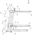
Figure 2 is a perspective view of a guide rail assembly in an elevator system according to an example of the present disclosure; -
Figures 3a and 3b are perspective and top views of the guide rail assembly of -
Figure 2 in a pre-assembled state; and -
Figure 4 is a front view of the guide rail assembly ofFigure 2 in an assembled state with adjacent guide rails vertically connected together. - In an example of the prior art, as seen in
Figures 1a and 1b , a guide rail assembly 1 comprises aguide rail bracket 2 horizontally connecting acar guide rail 4 to a pair of left and rightcounterweight guide rails guide rail bracket 2 is attached to thecar guide rail 4 by a clampingbracket 14. As seen most clearly inFigure 1a , the clampingbracket 14 includes ashim 15 and a pair ofclamps shim 15 by a screw. Theshim 15 has two rows of openings for throughfasteners 16 with two throughfasteners 16 in each row to fasten the clampingbracket 14 to theguide rail bracket 2. Thecar guide rail 4 is restrained between theclamps Figure 1b , i.e. held back against the shim 15.by being pinched between theclamps guide rail bracket 2 is attached to the leftcounterweight guide rail 6 by aninterface bracket 10a and to the rightcounterweight guide rail 8 by a mirrorimage interface bracket 10b. Eachinterface bracket fasteners 12 that attach theinterface bracket counterweight guide rail 6, 8 (in a similar manner to theclamps - As shown in
Figure 1b , the way that adjacent guide rails are connected together vertically in the prior art is by fishplates that span the joint.Figure 1b shows afishplate 20a vertically connecting together adjacent leftcounterweight guide rails 6, anotherfishplate 20b vertically connecting together adjacentcar guide rails 4, and anotherfishplate 20c vertically connecting together adjacent right counterweight guide rails 8. When installing theguide rails Figures 1a and 1b must be provided and assembled together. - In an example of the present disclosure, as seen in
Figures 2-4 , aguide rail assembly 100 comprises aguide rail bracket 102 horizontally connecting acar guide rail 104 to a pair of left and rightcounterweight guide rails first end portion 103 of theguide rail bracket 102 is attached to the leftcounterweight guide rail 106 by afirst interface bracket 110a and asecond end portion 105 of theguide rail bracket 102 is attached to the rightcounterweight guide rail 108 by a mirror imagesecond interface bracket 110b. Anintermediate portion 107 of theguide rail bracket 102 is attached to thecar guide rail 104 by athird interface bracket 114. In this example, eachinterface bracket openings 113 receiving throughfasteners 112 that attach theinterface bracket corresponding guide rail third interface bracket 114, two openings in each row receive throughfasteners 112 for a firstcar guide rail 104 while the other twoopenings 113 in each row can receive through fasteners for a second adjacent car guide rail (not shown). This means that each of the first, second andthird interface brackets Figure 4 , described further below. In this example, there is no need for separate fishplates to vertically connect together adjacent guide rails. Furthermore, theinterface brackets guide rails Figure 1 . - Referring to
Figure 2 , it can be seen that thethird interface bracket 114 is U-shaped, comprising abase plate 130 that forms the connecting plate and is arranged to face theguide rail bracket 102, and first andsecond side flanges base plate 130 that space thebase plate 130 away from theguide rail bracket 102. The first andsecond side flanges base plate 130 and terminate in first andsecond fastening plates guide rail bracket 102. - Referring again to
Figure 2 , it can be seen that the first andsecond interface brackets counterweight guide rails second interface brackets first plate guide rail bracket 102 and asecond plate first plate counterweight guide rail second interface brackets third plate first plate second plate third plate second plate second interface brackets first plate second plate second plate third plate - As can be seen most clearly for the
second interface bracket 110b, thethird plate 144b comprises a pair of openings for throughfasteners 146 to attach theinterface bracket 110b to a support bracket 148b. Each support bracket, for example the support bracket 148b seen inFigure 2 , is a foot configured to fixedly mount theguide rail bracket 102 to a wall, e.g. the wall of a hoistway or building. Such support brackets are provided at both ends of theguide rail bracket 102. - As shown in
Figure 3a , in a pre-assembled state of theguide rail assembly 100, the first, second andthird interface brackets guide rail bracket 102 and to theguide rails guide rails guide rail bracket 102.Figure 3b shows how this is achieved by attaching each of theinterface brackets guide rail bracket 102 by a single throughfastener 112. The throughfasteners 112 may be loosely attached so that theguide rails guide rail bracket 102 once theguide rail assembly 100 is in situ. This pre-assembled state is compact for ease of transportation. Theguide rail assembly 100 in this pre-assembled state may be hoisted more easily to a desired vertical position (e.g. in a hoistway) ready for installation. - As shown in
Figure 4 , in an assembled state of theguide rail assembly 100, the first, second andthird interface brackets guide rail bracket 102 and to theguide rails guide rails guide rail bracket 102. During installation, theguide rails guide rail bracket 102, for example by loosening the throughfasteners 112 seen inFig. 3b and then re-tightening the throughfasteners 112 once theguide rails guide rail bracket 102. Then additional throughfasteners 112 are employed to further attach theinterface brackets guide rail bracket 102. After the guide rail assembly has been unfolded, adjacent first and second leftcounterweight guide rails 106 are attached to thefirst interface bracket 110a so as to be vertically connected together, adjacent first and second rightcounterweight guide rails 108 are attached to thesecond interface bracket 110b so as to be vertically connected together, and adjacent first and secondcar guide rails 104 are attached to thethird interface bracket 114 so as to be vertically connected together. No additional fishplates are required. - The guide rails disclosed herein have been described, by way of example, as standard T-profile guide rails i.e. wherein the guide rail includes a base and a blade extending therefrom. However, it will be appreciated that the present disclosure is not limited to T-profile guide rails and may be applied to guide rails of any profile. The guide rails may be monolithic, e.g. rigid steel guide rails, or formed of metal sheet, or made in any other suitable way as known to the skilled person.
- It will be appreciated by those skilled in the art that the present disclosure has been illustrated by describing one or more specific examples thereof, but is not limited to these aspects; many variations and modifications are possible, within the scope of the accompanying claims.
Claims (15)
- A guide rail bracket assembly for connecting a car guide rail (104) to a pair of left and right counterweight guide rails (106,108) in an elevator system, the guide rail bracket assembly comprising:a guide rail bracket (102) for horizontally connecting the car guide rail (104) to the pair of left and right counterweight guide rails (106, 108), the guide rail bracket (102) comprising a first end portion (103) for attachment to the left counterweight guide rail (106), a second end portion (105) for attachment to the right counterweight guide rail (108), and an intermediate portion (107) for attachment to the car guide rail (104);a first interface bracket (110a) for attaching the first end portion (103) to the left counterweight guide rail (106), a second interface bracket (110b) for attaching the second end portion (105) to the right counterweight guide rail (108), and a third interface bracket (114) for attaching the intermediate portion (107) to the car guide rail (104);wherein at least one of the first, second and third interface brackets (110a, 110b, 114) forms a connecting plate (142a, 142b, 130) for vertically connecting together adjacent guide rails.
- A guide rail bracket assembly according to claim 1, wherein each of the first, second and third interface brackets (110a, 110b, 114) forms a connecting plate for vertically connecting together adjacent guide rails.
- A guide rail bracket assembly according to claim 1 or 2, wherein the connecting plate (142a, 142b, 130) comprises at least four openings (113), each opening (113) arranged to receive a through fastener (112) for direct attachment of the left counterweight guide rail (106), right counterweight guide rail (108) or car guide rail (104) to its respective interface bracket (110a, 110b, 114).
- A guide rail bracket assembly according to any preceding claim, wherein the first and second interface brackets (110a, 110b) are L-shaped, comprising a first plate (140a, 140b) arranged to face the guide rail bracket (102) and a second plate (142a, 142b), substantially orthogonal to the first plate (140a, 140b), the second plate (142a, 142b) forming the connecting plate and arranged to face a base of the left or right counterweight guide rail (106, 108).
- A guide rail bracket assembly according to claim 4, wherein the first and second interface brackets (110a, 110b) further comprise a third plate (144a, 144b), substantially orthogonal to the first plate (140a, 140b) and the second plate (142a, 142b), the third plate (144a, 144b) extending away from the second plate (142a, 142b) that forms the connecting plate.
- A guide rail bracket assembly according to claim 5, wherein the third plate (144a, 144b) comprises one or more openings for through fasteners (146) to attach the respective first or second interface bracket (110a, 110b) to a support bracket (148b).
- A guide rail bracket assembly according to any preceding claim, further comprising a support bracket (148b) configured to fixedly mount the guide rail bracket (102) to a wall.
- A guide rail bracket assembly according to claim 7, wherein the support bracket comprises a first support bracket attached to the first interface bracket (110a) and a second support bracket (148b) attached to the second interface bracket (110b).
- A guide rail bracket assembly according to any preceding claim, wherein the third interface bracket (114) is U-shaped, comprising a base plate (130) that forms the connecting plate and is arranged to face the guide rail bracket (102), and first and second side flanges (132a, 132b) on opposed sides of the base plate (130) that space the base plate (130) away from the guide rail bracket (102).
- A guide rail bracket assembly according to claim 9, wherein the first and second side flanges (132a, 132b) extend away from the base plate (130) and terminate in first and second fastening plates (134a, 134b) arranged to be fastened to the guide rail bracket (102).
- A guide rail assembly (100) comprising:the guide rail bracket assembly of any preceding claim;a left counterweight guide rail (106) attached to the first interface bracket (110a);a right counterweight guide rail (108) attached to the second interface bracket (110b); anda car guide rail (104) attached to the third interface bracket (114);wherein the first, second and third interface brackets (110a, 110b, 114) are attached to the guide rail bracket (102).
- A guide rail assembly (100) according to claim 11, wherein at least one of the left counterweight guide rail (106), right counterweight guide rail (108) and car guide rail (104) is directly attached to its respective interface bracket (110a, 110b, 114) by a through fastener (112).
- A guide rail assembly according to claim 11 or 12, wherein:in a pre-assembled state, the first, second and third interface brackets (110a, 110b, 114) are attached to the guide rail bracket (102) and to the guide rails (104, 106, 108) such that the guide rails run substantially parallel to the guide rail bracket, andin an assembled state, the first, second and third interface brackets (110a, 110b, 114) are attached to the guide rail bracket (102) and to the guide rails (104, 106, 108) such that the guide rails run substantially perpendicular to the guide rail bracket.
- A guide rail assembly according to any of claims 11-13, wherein:adjacent first and second left counterweight guide rails (106) are attached to the first interface bracket (110a) so as to be vertically connected together; and/oradjacent first and second right counterweight guide rails (108) are attached to the second interface bracket (110b) so as to be vertically connected together; and/oradjacent first and second car guide rails (104) are attached to the third interface bracket (114) so as to be vertically connected together.
- A method of installing guide rails in an elevator system, comprising:providing a guide rail assembly in a pre-assembled state, the guide rail assembly comprising a guide rail bracket attached to first, second and third interface brackets, the first interface bracket attached to a left counterweight guide rail, the second interface bracket attached to a right counterweight guide rail, and the third interface bracket attached to a car guide rail, wherein the guide rail bracket and the guide rails are attached to the interface brackets such that the guide rails run substantially parallel to the guide rail bracket; andassembling the guide rail bracket to horizontally connect the car guide rail to the left and right counterweight guide rails by further attaching the guide rail bracket to the first, second and third interface brackets and further attaching the guide rails to the first, second and third interface brackets such that the guide rails run substantially perpendicular to the guide rail bracket.
Priority Applications (3)
| Application Number | Priority Date | Filing Date | Title |
|---|---|---|---|
| EP19315101.6A EP3782945B1 (en) | 2019-08-23 | 2019-08-23 | Guide rail bracket assembly |
| US16/835,585 US20210053797A1 (en) | 2019-08-23 | 2020-03-31 | Guide rail bracket assembly |
| CN202010440764.8A CN112408150B (en) | 2019-08-23 | 2020-05-22 | Guide rail bracket assembly |
Applications Claiming Priority (1)
| Application Number | Priority Date | Filing Date | Title |
|---|---|---|---|
| EP19315101.6A EP3782945B1 (en) | 2019-08-23 | 2019-08-23 | Guide rail bracket assembly |
Publications (2)
| Publication Number | Publication Date |
|---|---|
| EP3782945A1 true EP3782945A1 (en) | 2021-02-24 |
| EP3782945B1 EP3782945B1 (en) | 2023-04-05 |
Family
ID=67953726
Family Applications (1)
| Application Number | Title | Priority Date | Filing Date |
|---|---|---|---|
| EP19315101.6A Active EP3782945B1 (en) | 2019-08-23 | 2019-08-23 | Guide rail bracket assembly |
Country Status (3)
| Country | Link |
|---|---|
| US (1) | US20210053797A1 (en) |
| EP (1) | EP3782945B1 (en) |
| CN (1) | CN112408150B (en) |
Families Citing this family (2)
| Publication number | Priority date | Publication date | Assignee | Title |
|---|---|---|---|---|
| WO2021245062A1 (en) * | 2020-06-05 | 2021-12-09 | Inventio Ag | Rail-fastening system |
| CN114267233A (en) * | 2021-12-08 | 2022-04-01 | 广东非凡教育设备有限公司 | Frame construction of emulation elevator |
Citations (5)
| Publication number | Priority date | Publication date | Assignee | Title |
|---|---|---|---|---|
| JPS62197671U (en) * | 1986-06-05 | 1987-12-16 | ||
| JPH0419570U (en) * | 1990-06-04 | 1992-02-19 | ||
| JPH0952675A (en) * | 1995-08-15 | 1997-02-25 | Toshiba Fa Syst Eng Kk | Elevator guide rail mounting device |
| JP2005104673A (en) * | 2003-09-30 | 2005-04-21 | Toshiba Elevator Co Ltd | Elevator guide rail fixing device |
| US20180009633A1 (en) | 2015-01-23 | 2018-01-11 | Otis Elevator Company | Elevator system rails |
Family Cites Families (7)
| Publication number | Priority date | Publication date | Assignee | Title |
|---|---|---|---|---|
| FI91849C (en) * | 1993-09-10 | 1994-08-25 | Kone Oy | Method for attaching and adjusting guides |
| KR20050081483A (en) * | 2004-02-13 | 2005-08-19 | 김유리 | Rail for elevator |
| JP2011136817A (en) * | 2009-12-28 | 2011-07-14 | Hitachi Ltd | Guide rail mounting tool and guide rail fixing method |
| CN105492361B (en) * | 2013-08-29 | 2017-08-01 | 三菱电机株式会社 | The fixing device of guide rail for elevator |
| CN203638924U (en) * | 2013-12-17 | 2014-06-11 | 康力电梯股份有限公司 | Support for lift car guide rail and counter weight guide rail |
| CN205739906U (en) * | 2016-06-27 | 2016-11-30 | 西继迅达(许昌)电梯有限公司 | A kind of Elevator car counterweight rail bracket |
| CN207258956U (en) * | 2017-09-29 | 2018-04-20 | 邓潮森 | The mounting structure of connection plate for elevator guide rail, guide rail and rail brackets |
-
2019
- 2019-08-23 EP EP19315101.6A patent/EP3782945B1/en active Active
-
2020
- 2020-03-31 US US16/835,585 patent/US20210053797A1/en not_active Abandoned
- 2020-05-22 CN CN202010440764.8A patent/CN112408150B/en active Active
Patent Citations (5)
| Publication number | Priority date | Publication date | Assignee | Title |
|---|---|---|---|---|
| JPS62197671U (en) * | 1986-06-05 | 1987-12-16 | ||
| JPH0419570U (en) * | 1990-06-04 | 1992-02-19 | ||
| JPH0952675A (en) * | 1995-08-15 | 1997-02-25 | Toshiba Fa Syst Eng Kk | Elevator guide rail mounting device |
| JP2005104673A (en) * | 2003-09-30 | 2005-04-21 | Toshiba Elevator Co Ltd | Elevator guide rail fixing device |
| US20180009633A1 (en) | 2015-01-23 | 2018-01-11 | Otis Elevator Company | Elevator system rails |
Also Published As
| Publication number | Publication date |
|---|---|
| CN112408150B (en) | 2023-10-27 |
| US20210053797A1 (en) | 2021-02-25 |
| EP3782945B1 (en) | 2023-04-05 |
| CN112408150A (en) | 2021-02-26 |
Similar Documents
| Publication | Publication Date | Title |
|---|---|---|
| US6598361B2 (en) | Mullion splice joint design | |
| US9683367B1 (en) | Curtain wall mullion anchoring system | |
| EP2535948A1 (en) | Structure-supporting structure, frame for structure, method for constructing structure using said frame, and solar power generating system | |
| EP3782945B1 (en) | Guide rail bracket assembly | |
| US5320193A (en) | Safety Anchor | |
| US3199642A (en) | Rail positioning and fastening device | |
| US6681536B1 (en) | Mounting structure and method for viscosity system damping wall | |
| US10519006B2 (en) | Elevator guide rail bracket and method for securing a guide rail | |
| US6601350B1 (en) | Structure for installing a viscous vibration-damping wall and method of installing the same | |
| EP1031669B1 (en) | Building frames with sigma-profile | |
| US5119908A (en) | Procedure for mounting the guide rails for an elevator car or counterweight, and a mounting system implementing the procedure | |
| EP2174902B1 (en) | Elevator guide rail fixing brackets | |
| EP0425313A2 (en) | Mount system for elevator guide rails | |
| JPH0791006B2 (en) | Elevator hoistway compartment | |
| US10882718B2 (en) | Guide rail fixing device | |
| JPS6214057Y2 (en) | ||
| JP2992020B1 (en) | Temporary enclosure panel mounting bracket | |
| EP4249415A1 (en) | Guide rail support structure and elevator | |
| JPH06102510B2 (en) | Elevator guide rail device | |
| EP0805774A1 (en) | A method and apparatus for installing and balancing an elevator car | |
| CN213143833U (en) | It attaches wall connection structure to choose structure pin-connected panel | |
| JPH07117947A (en) | Fascia plate for elevator | |
| KR102280432B1 (en) | Variable steel girder structure for deflection prevention | |
| JPS6211892Y2 (en) | ||
| JP2014037279A (en) | Method of erecting elevator guide rail |
Legal Events
| Date | Code | Title | Description |
|---|---|---|---|
| PUAI | Public reference made under article 153(3) epc to a published international application that has entered the european phase |
Free format text: ORIGINAL CODE: 0009012 |
|
| STAA | Information on the status of an ep patent application or granted ep patent |
Free format text: STATUS: THE APPLICATION HAS BEEN PUBLISHED |
|
| AK | Designated contracting states |
Kind code of ref document: A1 Designated state(s): AL AT BE BG CH CY CZ DE DK EE ES FI FR GB GR HR HU IE IS IT LI LT LU LV MC MK MT NL NO PL PT RO RS SE SI SK SM TR |
|
| AX | Request for extension of the european patent |
Extension state: BA ME |
|
| STAA | Information on the status of an ep patent application or granted ep patent |
Free format text: STATUS: REQUEST FOR EXAMINATION WAS MADE |
|
| 17P | Request for examination filed |
Effective date: 20210824 |
|
| RBV | Designated contracting states (corrected) |
Designated state(s): AL AT BE BG CH CY CZ DE DK EE ES FI FR GB GR HR HU IE IS IT LI LT LU LV MC MK MT NL NO PL PT RO RS SE SI SK SM TR |
|
| STAA | Information on the status of an ep patent application or granted ep patent |
Free format text: STATUS: EXAMINATION IS IN PROGRESS |
|
| 17Q | First examination report despatched |
Effective date: 20211122 |
|
| GRAP | Despatch of communication of intention to grant a patent |
Free format text: ORIGINAL CODE: EPIDOSNIGR1 |
|
| STAA | Information on the status of an ep patent application or granted ep patent |
Free format text: STATUS: GRANT OF PATENT IS INTENDED |
|
| INTG | Intention to grant announced |
Effective date: 20221011 |
|
| GRAS | Grant fee paid |
Free format text: ORIGINAL CODE: EPIDOSNIGR3 |
|
| GRAA | (expected) grant |
Free format text: ORIGINAL CODE: 0009210 |
|
| STAA | Information on the status of an ep patent application or granted ep patent |
Free format text: STATUS: THE PATENT HAS BEEN GRANTED |
|
| AK | Designated contracting states |
Kind code of ref document: B1 Designated state(s): AL AT BE BG CH CY CZ DE DK EE ES FI FR GB GR HR HU IE IS IT LI LT LU LV MC MK MT NL NO PL PT RO RS SE SI SK SM TR |
|
| REG | Reference to a national code |
Ref country code: GB Ref legal event code: FG4D |
|
| REG | Reference to a national code |
Ref country code: DE Ref legal event code: R096 Ref document number: 602019027156 Country of ref document: DE |
|
| REG | Reference to a national code |
Ref country code: CH Ref legal event code: EP |
|
| REG | Reference to a national code |
Ref country code: AT Ref legal event code: REF Ref document number: 1558132 Country of ref document: AT Kind code of ref document: T Effective date: 20230415 |
|
| REG | Reference to a national code |
Ref country code: IE Ref legal event code: FG4D |
|
| REG | Reference to a national code |
Ref country code: LT Ref legal event code: MG9D |
|
| REG | Reference to a national code |
Ref country code: NL Ref legal event code: MP Effective date: 20230405 |
|
| REG | Reference to a national code |
Ref country code: AT Ref legal event code: MK05 Ref document number: 1558132 Country of ref document: AT Kind code of ref document: T Effective date: 20230405 |
|
| PG25 | Lapsed in a contracting state [announced via postgrant information from national office to epo] |
Ref country code: NL Free format text: LAPSE BECAUSE OF FAILURE TO SUBMIT A TRANSLATION OF THE DESCRIPTION OR TO PAY THE FEE WITHIN THE PRESCRIBED TIME-LIMIT Effective date: 20230405 |
|
| PG25 | Lapsed in a contracting state [announced via postgrant information from national office to epo] |
Ref country code: SE Free format text: LAPSE BECAUSE OF FAILURE TO SUBMIT A TRANSLATION OF THE DESCRIPTION OR TO PAY THE FEE WITHIN THE PRESCRIBED TIME-LIMIT Effective date: 20230405 Ref country code: PT Free format text: LAPSE BECAUSE OF FAILURE TO SUBMIT A TRANSLATION OF THE DESCRIPTION OR TO PAY THE FEE WITHIN THE PRESCRIBED TIME-LIMIT Effective date: 20230807 Ref country code: NO Free format text: LAPSE BECAUSE OF FAILURE TO SUBMIT A TRANSLATION OF THE DESCRIPTION OR TO PAY THE FEE WITHIN THE PRESCRIBED TIME-LIMIT Effective date: 20230705 Ref country code: ES Free format text: LAPSE BECAUSE OF FAILURE TO SUBMIT A TRANSLATION OF THE DESCRIPTION OR TO PAY THE FEE WITHIN THE PRESCRIBED TIME-LIMIT Effective date: 20230405 Ref country code: AT Free format text: LAPSE BECAUSE OF FAILURE TO SUBMIT A TRANSLATION OF THE DESCRIPTION OR TO PAY THE FEE WITHIN THE PRESCRIBED TIME-LIMIT Effective date: 20230405 |
|
| PG25 | Lapsed in a contracting state [announced via postgrant information from national office to epo] |
Ref country code: RS Free format text: LAPSE BECAUSE OF FAILURE TO SUBMIT A TRANSLATION OF THE DESCRIPTION OR TO PAY THE FEE WITHIN THE PRESCRIBED TIME-LIMIT Effective date: 20230405 Ref country code: PL Free format text: LAPSE BECAUSE OF FAILURE TO SUBMIT A TRANSLATION OF THE DESCRIPTION OR TO PAY THE FEE WITHIN THE PRESCRIBED TIME-LIMIT Effective date: 20230405 Ref country code: LV Free format text: LAPSE BECAUSE OF FAILURE TO SUBMIT A TRANSLATION OF THE DESCRIPTION OR TO PAY THE FEE WITHIN THE PRESCRIBED TIME-LIMIT Effective date: 20230405 Ref country code: LT Free format text: LAPSE BECAUSE OF FAILURE TO SUBMIT A TRANSLATION OF THE DESCRIPTION OR TO PAY THE FEE WITHIN THE PRESCRIBED TIME-LIMIT Effective date: 20230405 Ref country code: IS Free format text: LAPSE BECAUSE OF FAILURE TO SUBMIT A TRANSLATION OF THE DESCRIPTION OR TO PAY THE FEE WITHIN THE PRESCRIBED TIME-LIMIT Effective date: 20230805 Ref country code: HR Free format text: LAPSE BECAUSE OF FAILURE TO SUBMIT A TRANSLATION OF THE DESCRIPTION OR TO PAY THE FEE WITHIN THE PRESCRIBED TIME-LIMIT Effective date: 20230405 Ref country code: GR Free format text: LAPSE BECAUSE OF FAILURE TO SUBMIT A TRANSLATION OF THE DESCRIPTION OR TO PAY THE FEE WITHIN THE PRESCRIBED TIME-LIMIT Effective date: 20230706 Ref country code: AL Free format text: LAPSE BECAUSE OF FAILURE TO SUBMIT A TRANSLATION OF THE DESCRIPTION OR TO PAY THE FEE WITHIN THE PRESCRIBED TIME-LIMIT Effective date: 20230405 |
|
| PGFP | Annual fee paid to national office [announced via postgrant information from national office to epo] |
Ref country code: FR Payment date: 20230720 Year of fee payment: 5 Ref country code: DE Payment date: 20230720 Year of fee payment: 5 |
|
| PG25 | Lapsed in a contracting state [announced via postgrant information from national office to epo] |
Ref country code: FI Free format text: LAPSE BECAUSE OF FAILURE TO SUBMIT A TRANSLATION OF THE DESCRIPTION OR TO PAY THE FEE WITHIN THE PRESCRIBED TIME-LIMIT Effective date: 20230405 |
|
| REG | Reference to a national code |
Ref country code: DE Ref legal event code: R097 Ref document number: 602019027156 Country of ref document: DE |
|
| PG25 | Lapsed in a contracting state [announced via postgrant information from national office to epo] |
Ref country code: SK Free format text: LAPSE BECAUSE OF FAILURE TO SUBMIT A TRANSLATION OF THE DESCRIPTION OR TO PAY THE FEE WITHIN THE PRESCRIBED TIME-LIMIT Effective date: 20230405 |
|
| PG25 | Lapsed in a contracting state [announced via postgrant information from national office to epo] |
Ref country code: SM Free format text: LAPSE BECAUSE OF FAILURE TO SUBMIT A TRANSLATION OF THE DESCRIPTION OR TO PAY THE FEE WITHIN THE PRESCRIBED TIME-LIMIT Effective date: 20230405 Ref country code: SK Free format text: LAPSE BECAUSE OF FAILURE TO SUBMIT A TRANSLATION OF THE DESCRIPTION OR TO PAY THE FEE WITHIN THE PRESCRIBED TIME-LIMIT Effective date: 20230405 Ref country code: RO Free format text: LAPSE BECAUSE OF FAILURE TO SUBMIT A TRANSLATION OF THE DESCRIPTION OR TO PAY THE FEE WITHIN THE PRESCRIBED TIME-LIMIT Effective date: 20230405 Ref country code: EE Free format text: LAPSE BECAUSE OF FAILURE TO SUBMIT A TRANSLATION OF THE DESCRIPTION OR TO PAY THE FEE WITHIN THE PRESCRIBED TIME-LIMIT Effective date: 20230405 Ref country code: DK Free format text: LAPSE BECAUSE OF FAILURE TO SUBMIT A TRANSLATION OF THE DESCRIPTION OR TO PAY THE FEE WITHIN THE PRESCRIBED TIME-LIMIT Effective date: 20230405 Ref country code: CZ Free format text: LAPSE BECAUSE OF FAILURE TO SUBMIT A TRANSLATION OF THE DESCRIPTION OR TO PAY THE FEE WITHIN THE PRESCRIBED TIME-LIMIT Effective date: 20230405 |
|
| PLBE | No opposition filed within time limit |
Free format text: ORIGINAL CODE: 0009261 |
|
| STAA | Information on the status of an ep patent application or granted ep patent |
Free format text: STATUS: NO OPPOSITION FILED WITHIN TIME LIMIT |
|
| PG25 | Lapsed in a contracting state [announced via postgrant information from national office to epo] |
Ref country code: MC Free format text: LAPSE BECAUSE OF FAILURE TO SUBMIT A TRANSLATION OF THE DESCRIPTION OR TO PAY THE FEE WITHIN THE PRESCRIBED TIME-LIMIT Effective date: 20230405 |
|
| 26N | No opposition filed |
Effective date: 20240108 |
|
| REG | Reference to a national code |
Ref country code: CH Ref legal event code: PL |
|
| PG25 | Lapsed in a contracting state [announced via postgrant information from national office to epo] |
Ref country code: MC Free format text: LAPSE BECAUSE OF FAILURE TO SUBMIT A TRANSLATION OF THE DESCRIPTION OR TO PAY THE FEE WITHIN THE PRESCRIBED TIME-LIMIT Effective date: 20230405 |
|
| PG25 | Lapsed in a contracting state [announced via postgrant information from national office to epo] |
Ref country code: LU Free format text: LAPSE BECAUSE OF NON-PAYMENT OF DUE FEES Effective date: 20230823 |