EP3782691A1 - Movable catheter - Google Patents
Movable catheter Download PDFInfo
- Publication number
- EP3782691A1 EP3782691A1 EP19787582.6A EP19787582A EP3782691A1 EP 3782691 A1 EP3782691 A1 EP 3782691A1 EP 19787582 A EP19787582 A EP 19787582A EP 3782691 A1 EP3782691 A1 EP 3782691A1
- Authority
- EP
- European Patent Office
- Prior art keywords
- wire
- tube
- end portion
- lumen
- catheter
- Prior art date
- Legal status (The legal status is an assumption and is not a legal conclusion. Google has not performed a legal analysis and makes no representation as to the accuracy of the status listed.)
- Pending
Links
Images




Classifications
-
- A—HUMAN NECESSITIES
- A61—MEDICAL OR VETERINARY SCIENCE; HYGIENE
- A61M—DEVICES FOR INTRODUCING MEDIA INTO, OR ONTO, THE BODY; DEVICES FOR TRANSDUCING BODY MEDIA OR FOR TAKING MEDIA FROM THE BODY; DEVICES FOR PRODUCING OR ENDING SLEEP OR STUPOR
- A61M25/00—Catheters; Hollow probes
- A61M25/01—Introducing, guiding, advancing, emplacing or holding catheters
- A61M25/0105—Steering means as part of the catheter or advancing means; Markers for positioning
- A61M25/0133—Tip steering devices
- A61M25/0147—Tip steering devices with movable mechanical means, e.g. pull wires
-
- A—HUMAN NECESSITIES
- A61—MEDICAL OR VETERINARY SCIENCE; HYGIENE
- A61M—DEVICES FOR INTRODUCING MEDIA INTO, OR ONTO, THE BODY; DEVICES FOR TRANSDUCING BODY MEDIA OR FOR TAKING MEDIA FROM THE BODY; DEVICES FOR PRODUCING OR ENDING SLEEP OR STUPOR
- A61M25/00—Catheters; Hollow probes
- A61M25/0021—Catheters; Hollow probes characterised by the form of the tubing
- A61M25/0023—Catheters; Hollow probes characterised by the form of the tubing by the form of the lumen, e.g. cross-section, variable diameter
- A61M25/0026—Multi-lumen catheters with stationary elements
-
- A—HUMAN NECESSITIES
- A61—MEDICAL OR VETERINARY SCIENCE; HYGIENE
- A61M—DEVICES FOR INTRODUCING MEDIA INTO, OR ONTO, THE BODY; DEVICES FOR TRANSDUCING BODY MEDIA OR FOR TAKING MEDIA FROM THE BODY; DEVICES FOR PRODUCING OR ENDING SLEEP OR STUPOR
- A61M25/00—Catheters; Hollow probes
- A61M25/01—Introducing, guiding, advancing, emplacing or holding catheters
- A61M25/0105—Steering means as part of the catheter or advancing means; Markers for positioning
- A61M25/0133—Tip steering devices
- A61M25/0147—Tip steering devices with movable mechanical means, e.g. pull wires
- A61M2025/015—Details of the distal fixation of the movable mechanical means
Definitions
- the present invention relates to a catheter, which is a medical treatment tool used for performing various types of treatments, examinations, and the like. More particularly, the invention relates to a movable catheter (steerable catheter) having a freely deflectable tip portion or the like.
- a medical treatment tool (such as a catheter for contrast agent injection, an electrode catheter, an ablation catheter, and a catheter sheath) is inserted into target tissue such as various organs (bile duct, heart, and so on) through a body cavity, a lumen, a blood vessel, or the like.
- a movable catheter is known as the medical treatment tool.
- the direction of the tip (distal end) of the catheter inserted into the body can be deflected by the operation of an operation portion provided on the base end (proximal end) side of the catheter disposed outside the body so that, for example, the movable catheter can be inserted with ease or is capable of approaching the target tissue with ease (see, for example, Patent Document 1 and Patent Document 2).
- the catheter described in Patent Document 1 is an endoscopic catheter used for X-ray contrast agent injection into a bile duct for intra-bile duct examination or the like.
- the tip portion of the catheter described in Patent Document 1 can be deflected (curved) by an operation wire being operated from the outside of the body such that the catheter is inserted into the duodenum via an endoscope and then easily reaches the bile duct by the tip portion being inserted from the duodenum side into the duodenal papilla.
- the catheter described in Patent Document 1 has a lumen into which the operation wire for deflecting the tip portion is inserted in addition to a large-diameter lumen used for contrast agent injection or the like.
- the operation wire is joined to the pointed tip that is provided in the tip portion of the catheter by means such as plasma welding, and thus it is possible to deflect the tip portion of the catheter by pulling the operation wire outside the body.
- the catheter described in Patent Document 2 which has a movable tip, is used so that, for example, an ablation catheter is guided to an area to be treated in the heart and a catheter ablation procedure is performed on the heart.
- the tip portion of the catheter described in Patent Document 2 can be deflected (curved) by an operation portion being operated from the outside of the body such that the tip of the ablation catheter is easily guided to a desired heart position.
- a catheter tube constituting the catheter described in Patent Document 2 has a main lumen into which various treatment tools are inserted and a pair of wire lumens at positions facing each other at an angle of 180° in the tube wall thereof.
- the part of the tip portion of the catheter tube to be deflected is set such that, for example, the rigidity thereof decreases in stages toward the tip, the tips of a pair of wires respectively inserted through the wire lumens are connected by means such as laser welding to the ring (pull ring) that is integrally mounted in the tip portion, and the base ends of the pair of wires are connected to the operation portion. Further, it is possible to pull one of the wires, loosen the other wire, and control the direction of the tube tip by operating the operation portion.
- the tip of the wire for deflection operation is connected and fixed to the member mounted in the tip portion of the catheter (pointed tip or pull ring) by means such as plasma welding and laser welding and there is a problem that the number of components is increased by the wire fixing member (pointed tip or pull ring) and the work of mounting the member on the catheter and the work of connecting and fixing the tip of the wire to the member are complicated.
- the catheter is structurally limited, examples of which include the necessity of reducing the tip opening area of the main lumen.
- the invention has been made in view of such circumstances, and an object thereof is to provide a movable catheter that enables the number of components to be reduced and enables the number of manufacturing steps to be reduced.
- a movable catheter is a movable catheter provided with a tube having a main lumen, in which the tube has a plurality of wire lumens outside the main lumen, and the plurality of wire lumens are spaced apart from each other and reach a distal end portion of the tube from a proximal end portion of the tube, and the tube includes at least one wire, a substantial half of the wire at one end portion side of the wire is inserted through one of the wire lumens, an intermediate part of the wire is folded back on the distal end portion of the tube, a substantial half of the wire at the other end portion side of the wire is inserted through another one of the wire lumens, and the one end portion and the other end portion of the wire are disposed at the proximal end side of the tube.
- the wire is folded back in one distal end portion of the wire lumen through which the substantial half on one end portion side thereof is inserted and another distal end portion of the wire lumen through which the substantial half on the other end side thereof is inserted. Accordingly, by simultaneously pulling both end portions (one end portion and the other end portion) of the wire disposed on the proximal end side of the tube, it is possible to apply a force for deflecting the distal end portion of the tube to the distal end portion of the tube. Accordingly, it is possible to deflect the distal end portion of the tube in accordance with the disposition of the pair of wire lumens through which the wire is inserted.
- the wire lumens comprise three or more wire lumens and the movable catheter comprises two or more wires. With this configuration, it is possible to deflect the distal end portion of the tube in two or more directions.
- a tube that has a single-lumen tube having the main lumen and at least one multi-lumen tube integrally disposed outside the single-lumen tube and having a plurality of the wire lumens can be used as the tube.
- a tube in which a plurality of wire lumens are formed in the tube wall of a single tube having a main lumen may be used as the tube, it is also possible to use the tube in which the multi-lumen tube is disposed outside the single-lumen tube. Then, the productivity of the movable catheter can be improved.
- a movable catheter is a movable catheter provided with a tube having a main lumen, in which the tube has a wire lumen outside the main lumen, and the wire lumen reaches a distal end portion of the tube from a proximal end portion of the tube, and the tube includes a wire, a substantial half of the wire at one end portion side of the wire is inserted through the wire lumen, an intermediate part of the wire is folded back on the distal end portion of the tube, a substantial half of the wire at the other end portion side of the wire is passed over an outside of the tube, and the one end portion and the other end portion of the wire are disposed at the proximal end side of the tube.
- a movable catheter is a movable catheter provided with a tube having a main lumen, in which the tube has a wire lumen outside the main lumen, and the wire lumen reaches a distal end portion of the tube from a proximal end portion of the tube, and the tube includes a wire, a substantial half of the wire at one end portion side of the wire is inserted through the wire lumen, an intermediate part of the wire is folded back on the distal end portion of the tube, a substantial half of the wire of the other end portion side of the wire is inserted through the main lumen, and the one end portion and the other end portion of the wire are disposed at the proximal end side of the tube.
- the wire is folded back in the distal end portion of the wire lumen through which the substantial half on one end side thereof is inserted and the substantial half on the other end side thereof is passed through the outside of the tube or the inside of the main lumen. Accordingly, by simultaneously pulling both end portions (one end portion and the other end portion) of the wire disposed on the proximal end side of the tube, it is possible to apply a force for deflecting the distal end portion of the catheter tube to the distal end portion of the catheter tube. Accordingly, it is possible to deflect the distal end portion of the tube in accordance with the disposition of the wire lumen through which the wire is inserted.
- the catheter sheath (movable sheath) as the movable catheter of the present embodiment is a catheter that is inserted prior to an electrode catheter for detecting an electrocardiogram, an ablation catheter for cauterizing an affected area, and the like and guides the electrode catheter, the ablation catheter, and the like when, for example, catheter ablation is performed.
- the catheter sheath will be described below as an example of the movable catheter to which the invention is applied, the invention is also applicable to an electrode catheter, an ablation catheter, a movable endoscopic catheter used for X-ray contrast agent injection into a bile duct for intra-bile duct examination or the like, and other movable catheters.
- the catheter ablation is a treatment method for treating cardiac arrhythmia and is a treatment method by which an ablation catheter having a highfrequency electrode in its tip portion is inserted through a blood vessel into the myocardial tissue that has caused the cardiac arrhythmia, coagulative necrosis is caused by the myocardial tissue or its vicinity being cauterized at approximately 60°C to 70°C, and the arrhythmic circuit is interrupted.
- a catheter sheath (movable catheter) 1 is configured to include a sheath main body (tube) 2, an operation portion 3, a grip portion 4, and a pair of wires W1 and W2.
- the sheath main body 2 is a hollow tube. Although not illustrated, a multilayer tube including a plurality of resin layers and a braid layer made of, for example, reticulated stainless steel is used as the sheath main body 2. A part of the distal end side of the sheath main body 2 is a deflection portion 21 capable of deflecting in any direction.
- the deflection portion 21 is set to be less rigid (more flexible) than the rest thereof. Further, in the deflection portion 21, the rigidity is set to decrease gradually or in stages toward the tip thereof.
- the material of the sheath main body 2 is not particularly limited insofar as the material has flexibility.
- the material of the sheath main body 2 is preferably a thermoplastic resin or a thermoplastic elastomer.
- examples thereof include polyamide-based elastomer such as polyether block amide copolymer, polyamide, polyimide, polyamide-imide, polyethylene terephthalate, polyethylene, polypropylene, polyurethane, ethylene-vinyl acetate copolymer, polyvinyl chloride, polytetrafluoroethylene, tetrafluoroethylene-hexafluoropropylene copolymer, and tetrafluoroethylene-perfluoroalkyl vinyl ether copolymer.
- An insertion hole through which the proximal end side part of the sheath main body 2 is inserted is formed in the operation portion 3 and the grip portion 4 attached to the proximal end side of the sheath main body 2.
- a sheath hub 41a is attached to the proximal end of the grip portion 4.
- the sheath hub 41a has a lumen.
- the sheath main body 2 in the grip portion 4 is attached to the proximal end side of the sheath hub 41a such that the lumen of the sheath hub 41a and a main lumen 22 of the sheath main body 2 communicate with each other.
- a catheter insertion port provided with a hemostatic valve is formed on the distal end side of the sheath hub 41a.
- a side injection tube is formed in the side portion of the sheath hub 41a and a three-way stopcock 41c is attached to the side injection tube via a tube 41b. It is possible to suction blood in the body or send a liquid medicine into the body by attaching a syringe or the like to the three-way stopcock 41c.
- the tip protection member 29 has a lumen substantially equal in diameter to the main lumen 22 of the sheath main body 2 and is integrally joined (fixed) to the distal end portion of the sheath main body 2 by heat fusion or the like. Alternatively, the tip protection member 29 may be omitted.
- wire lumens (sub-lumens) 23a to 23d substantially parallel to the main lumen 22 are formed so as to surround the outside of the main lumen 22.
- the wire lumens 23a to 23d are formed from the proximal end portion of the sheath main body 2 to the distal end portion of the sheath main body 2.
- the wire lumens 23a to 23d are formed outside the main lumen 22, around the central axis of the sheath main body 2, and apart from each other at an angular pitch (angular interval) of approximately 90°.
- the wire lumens 23a to 23d are formed so as to open to the distal end surface of the sheath main body 2 to which the tip protection member 29 is joined.
- the wire lumens 23a to 23d may be formed so as to open to the side surface of the sheath main body 2 near the distal end surface of the sheath main body 2 without reaching the distal end surface of the sheath main body 2 to which the tip protection member 29 is joined.
- the distal end of the wire lumen 23a and the distal end of the wire lumen 23b may communicate with each other and the distal end of the wire lumen 23c and the distal end of the wire lumen 23d may communicate with each other near the distal end surface of the sheath main body 2 without the wire lumens 23a to 23d opening to the outside of the sheath main body 2.
- these communicating portions may be formed in a substantially U shape so as not to hinder the insertion of the wires W1 and W2.
- the single wire W1 is inserted through the wire lumen 23a and the wire lumen 23b, and the single wire W2 is inserted through the wire lumen 23c and the wire lumen 23d.
- the wires W1 and W2 are formed of metal such as stainless steel in the present embodiment, the wires W1 and W2 may be formed of another material such as resin.
- a substantial half W1a on one end portion side of the wire W1 is inserted through the wire lumen 23a, an intermediate part W1c thereof is folded back on the distal end surface of the sheath main body 2 to which the tip protection member 29 is joined, a substantial half W1b on the other end portion side thereof is inserted through the wire lumen 23b, and both end portions (one end portion and the other end portion) thereof are disposed so as to be positioned in the operation portion 3 on the proximal end side of the sheath main body 2.
- a substantial half W2a on one end portion side of the wire W2 is inserted through the wire lumen 23c, an intermediate part W2c thereof is folded back on the distal end surface of the sheath main body 2 to which the tip protection member 29 is joined, a substantial half W2b on the other end portion side thereof is inserted through the wire lumen 23d, and both end portions (one end portion and the other end portion) thereof are disposed so as to be positioned in the operation portion 3 on the proximal end side of the sheath main body 2.
- Both end portions of the wire W1 and both end portions of the wire W2 are pulled out from the side holes that are provided in the sheath main body 2 in the operation portion 3 provided on the proximal end side of the sheath main body 2 and are connected to the operation portion 3 (a rotation operation member 31).
- the operation portion 3 has a pair of projection-shaped grip sections 32 and 32 and is held by a holding portion 42 provided on the tip (distal end) side of the grip portion 4 via a screw-type knob member 5.
- both the wire W1 and the wire W2 are in a tensionless state (or in a state of being tense loosely and substantially evenly) and the deflection portion 21 at the tip of the sheath main body 2 is in a linearly extended state as illustrated in Fig. 1 .
- the rotation operation member 31 is pressed by the holding portion 42 by the knob member 5 being rotated clockwise and tightened, the rotation operation member 31 is fixed at the current position, and the shape of the deflection portion 21 is fixed.
- the knob member 5 is rotated counterclockwise and loosened contrary to be above, and then the rotation operation member 31 is loosely pressed by the holding portion 42 and the rotation operation member 31 becomes rotatable. As a result, the fixing of the shape of the deflection portion 21 is released and it is possible to adjust the state of deflection of the deflection portion 21 by gripping the grip section 32 and rotating the rotation operation member 31.
- the wire W1 is folded back in the distal end portion of the wire lumen 23a through which the substantial half W1a on one end portion side thereof is inserted and the distal end portion of the wire lumen 23b through which the substantial half W1b on the other end side thereof is inserted. Accordingly, by pulling both end portions of the wire W1 disposed on the proximal end side of the sheath main body 2, it is possible to apply a force for deflecting the distal end portion of the sheath main body 2 to the distal end portion of the sheath main body 2.
- a force for deflecting the deflection portion 21 is applied by both the substantial half W1a of the wire W1 inserted through the wire lumen 23a and the substantial half W1b inserted through the wire lumen 23b being pulled. Accordingly, it is possible to apply the force to a relatively wide range in the circumferential direction of the sheath main body 2 in accordance with the interval (angular interval) between the wire lumen 23a and the wire lumen 23b. The same applies to the wire W2. As a result, the force that is applied to the wire and the risk of wire breakage that is entailed by the deflection operation are smaller than in the related art in which the deflection operation is performed by the single unfolded wire inserted through a single lumen being pulled.
- the wire W1 and the wire W2 that are used in the embodiment described above have the same specifications such as the same wire diameter (cross-sectional area), the specifications of the wire W1 and the wire W2 may differ from each other.
- the wire W1 may be larger in wire diameter (cross-sectional area) than the wire W2.
- the wire lumens 23a to 23d are arranged at an equal angular pitch (90° pitch) in the embodiment described above, the wire lumens 23a to 23d may be arranged at different angular intervals without having to be arranged at the equal angular pitch. By appropriately setting the angular intervals, it is possible to appropriately set the curvature of the deflection portion 21 or the direction of deflection of the deflection portion 21.
- wire W1 inserted through the wire lumen 23a and the wire lumen 23b and the wire W2 inserted through the wire lumen 23c and the wire lumen 23d are used in the embodiment described above
- a configuration in which four wires are used with a wire W3 and a wire W4 added may be adopted as illustrated in Figs. 3A to 3C .
- a substantial half W3a on one end portion side of the wire W3 is inserted through the wire lumen 23a, an intermediate part W3c thereof is folded back on the distal end surface of the sheath main body 2 to which the tip protection member 29 is joined, and a substantial half W3b on the other end portion side thereof is inserted through the wire lumen 23c.
- a substantial half W4a on one end portion side of the wire W4 is inserted through the wire lumen 23b, an intermediate part W4c thereof is folded back on the distal end surface of the sheath main body 2 to which the tip protection member 29 is joined, and a substantial half W4b on the other end portion side thereof is inserted through the wire lumen 23d.
- the number of wire lumens 23a to 23d and the four wires W1 to W4 are provided has been described in the example illustrated in Figs. 3A to 3C , the number of wire lumens can be increased or decreased and the number of wires can be accordingly increased or decreased as illustrated in, for example, Figs. 4A to 4C .
- Fig. 4A six wire lumens 24a are provided at an angular pitch of 60° and six wires W5 are provided.
- the deflection portion 21 can be deflected in six directions in a case where the wires W5 are pulled one by one and it is possible to deflect the deflection portion 21 by 360° in any direction by appropriately selecting a combination of two adjacent wires W5 and adjusting the balance of the forces that respectively pull the wires.
- three wire lumens 25a are provided at an angular pitch of 120° and three wires W6 are provided.
- the deflection portion 21 can be deflected in three directions in a case where the wires W6 are pulled one by one and it is possible to deflect the deflection portion 21 by 360° in any direction by appropriately selecting a combination of two adjacent wires W6 and adjusting the balance of the forces that respectively pull the wires.
- 24 wire lumens 26a are provided at an angular pitch of 15° and 24 wires W7 are provided.
- the deflection portion 21 can be deflected in 24 directions in a case where the wires W7 are pulled one by one.
- the number of wire lumens may be two or more, and the number of wires may be one or more.
- the numbers may be different from each other.
- the number of wires may be smaller than the number of wire lumens.
- both end portions of the wire are inserted through the pair of wire lumens that are adjacent to each other in each of the examples illustrated in Figs. 4A to 4C
- one pair of wire lumens may be, for example, intermittently selected and both end portions of the wire may be inserted therethrough.
- the deflection portion 21 can be deflected in one direction.
- the wire lumens are disposed at an angular interval of less than 180°. Then, the distal end portion of the sheath main body 2 can be easily deflected toward the pair of wire lumens through which the wire is inserted when both end portions of the wire are pulled at the same time.
- a substantial half W8a on one end portion side of a wire W8 is inserted through a wire lumen 27a formed in the sheath main body 2, an intermediate part W8c of the wire W8 is folded back at the distal end of the sheath main body 2, a substantial half W8b on the other end portion side of the wire W8 is passed through the outside of the sheath main body 2, and both end portions (one end portion and the other end portion) thereof are disposed on the proximal end side of the sheath main body 2.
- a substantial half W9a on one end portion side of a wire W9 is inserted through a wire lumen 27b formed in the sheath main body 2, an intermediate part W9c of the wire W9 is folded back at the distal end of the sheath main body 2, a substantial half W9b on the other end portion side of the wire W9 is passed through the outside of the sheath main body 2, and both end portions (one end portion and the other end portion) thereof are disposed on the proximal end side of the sheath main body 2.
- Figs. 5A to 5C it is possible to reduce the number of wire lumens while achieving the same action and effect as the configuration illustrated in Figs. 2A to 2C .
- the catheter sheath may be configured as illustrated in Figs. 6A to 6C .
- a substantial half W10a on one end portion side of a wire W10 is inserted through a wire lumen 28a formed in the sheath main body 2
- an intermediate part W10c of the wire W10 is folded back at the distal end of the sheath main body 2
- a substantial half W10b on the other end portion side of the wire W10 is inserted through the main lumen 22 formed in the sheath main body 2
- both end portions (one end portion and the other end portion) thereof are disposed on the proximal end side of the sheath main body 2.
- a substantial half W11a on one end portion side of a wire W11 is inserted through a wire lumen 28b formed in the sheath main body 2, an intermediate part W11c of the wire W11 is folded back at the distal end of the sheath main body 2, a substantial half W11b on the other end portion side of the wire W11 is inserted through the main lumen 22 formed in the sheath main body 2, and both end portions (one end portion and the other end portion) thereof are disposed on the proximal end side of the sheath main body 2. Also with this example illustrated in Figs. 6A to 6C , it is possible to reduce the number of wire lumens while achieving the same action and effect as the configuration illustrated in Figs. 2A to 2C .
- a single-lumen tube 200 having a main lumen 200a and at least one multi-lumen tube 201 having a plurality of wire lumens 201a and 201b may be combined and integrated with each other to be used as the sheath main body as illustrated in Fig. 7 .
- multi-lumen tubes 201 are disposed around the single-lumen tube 200, which has a substantially circular cross section and the main lumen 200a.
- the multi-lumen tube 201 has a substantially elliptical cross section and the pair of wire lumens 201a and 201b each having a substantially circular cross section.
- a substantial half W12a on one end portion side of a wire W12 (four in total) is inserted through the wire lumen 201a, and a substantial half W12b on the other end portion side of wire W12 is inserted through the wire lumen 201b.
- the single-lumen tube 200 and the multi-lumen tube 201 can be integrated with each other by, for example, adhesion by means of an adhesive or heat welding. Although it is not always easy to manufacture what has a plurality of wire lumens formed in the tube wall of the sheath main body 2 having the main lumen 22, it is possible to improve productivity by combining and integrating a plurality of tubes as described above.
- sheath main body is configured by the single-lumen tube 200 and the multi-lumen tube 201 being combined and integrated in the embodiment illustrated in Fig. 7
- a single-lumen tube 202 having a main lumen 202a and a plurality of long members 203 may be combined and integrated, as illustrated in Fig. 8 and such that a gap is formed between the single-lumen tube 202 and the long member 203, to be used as the sheath main body.
- the gap may be used as wire lumens 204a and 204b.
- each of the gaps has a substantially triangular cross section, and the four gaps are used as two pairs of wire lumens 204a and 204b.
- a substantial half W13a on one end portion side of a wire W13 (two in total) is inserted through the wire lumen 204a, and a substantial half W13b on the other end portion side of the wire W13 is inserted through the wire lumen 204b.
- the single-lumen tube 202 and the long member 203 can be integrated with each other by, for example, adhesion by means of an adhesive or heat welding. In this embodiment, no multi-lumen tube is necessary, and thus the productivity can be further improved.
Landscapes
- Health & Medical Sciences (AREA)
- Life Sciences & Earth Sciences (AREA)
- Engineering & Computer Science (AREA)
- Anesthesiology (AREA)
- Biophysics (AREA)
- Pulmonology (AREA)
- Biomedical Technology (AREA)
- Heart & Thoracic Surgery (AREA)
- Hematology (AREA)
- Animal Behavior & Ethology (AREA)
- General Health & Medical Sciences (AREA)
- Public Health (AREA)
- Veterinary Medicine (AREA)
- Mechanical Engineering (AREA)
- Media Introduction/Drainage Providing Device (AREA)
Abstract
Description
- The present invention relates to a catheter, which is a medical treatment tool used for performing various types of treatments, examinations, and the like. More particularly, the invention relates to a movable catheter (steerable catheter) having a freely deflectable tip portion or the like.
- A medical treatment tool (such as a catheter for contrast agent injection, an electrode catheter, an ablation catheter, and a catheter sheath) is inserted into target tissue such as various organs (bile duct, heart, and so on) through a body cavity, a lumen, a blood vessel, or the like. A movable catheter is known as the medical treatment tool. The direction of the tip (distal end) of the catheter inserted into the body can be deflected by the operation of an operation portion provided on the base end (proximal end) side of the catheter disposed outside the body so that, for example, the movable catheter can be inserted with ease or is capable of approaching the target tissue with ease (see, for example, Patent Document 1 and Patent Document 2).
- The catheter described in Patent Document 1 is an endoscopic catheter used for X-ray contrast agent injection into a bile duct for intra-bile duct examination or the like. The tip portion of the catheter described in Patent Document 1 can be deflected (curved) by an operation wire being operated from the outside of the body such that the catheter is inserted into the duodenum via an endoscope and then easily reaches the bile duct by the tip portion being inserted from the duodenum side into the duodenal papilla. The catheter described in Patent Document 1 has a lumen into which the operation wire for deflecting the tip portion is inserted in addition to a large-diameter lumen used for contrast agent injection or the like. The operation wire is joined to the pointed tip that is provided in the tip portion of the catheter by means such as plasma welding, and thus it is possible to deflect the tip portion of the catheter by pulling the operation wire outside the body.
- The catheter described in
Patent Document 2, which has a movable tip, is used so that, for example, an ablation catheter is guided to an area to be treated in the heart and a catheter ablation procedure is performed on the heart. The tip portion of the catheter described inPatent Document 2 can be deflected (curved) by an operation portion being operated from the outside of the body such that the tip of the ablation catheter is easily guided to a desired heart position. A catheter tube constituting the catheter described inPatent Document 2 has a main lumen into which various treatment tools are inserted and a pair of wire lumens at positions facing each other at an angle of 180° in the tube wall thereof. Further, the part of the tip portion of the catheter tube to be deflected is set such that, for example, the rigidity thereof decreases in stages toward the tip, the tips of a pair of wires respectively inserted through the wire lumens are connected by means such as laser welding to the ring (pull ring) that is integrally mounted in the tip portion, and the base ends of the pair of wires are connected to the operation portion. Further, it is possible to pull one of the wires, loosen the other wire, and control the direction of the tube tip by operating the operation portion. - However, in the related art such as Patent Document 1 and
Patent Document 2, the tip of the wire for deflection operation is connected and fixed to the member mounted in the tip portion of the catheter (pointed tip or pull ring) by means such as plasma welding and laser welding and there is a problem that the number of components is increased by the wire fixing member (pointed tip or pull ring) and the work of mounting the member on the catheter and the work of connecting and fixing the tip of the wire to the member are complicated. In addition, it is necessary to secure a region for providing the member in the structure of the catheter in order to provide the wire fixing member. As a result, there is another problem that the catheter is structurally limited, examples of which include the necessity of reducing the tip opening area of the main lumen. -
- Patent Document 1:
JP 2002-272675 A - Patent Document 2:
JP 2014-188039 A - The invention has been made in view of such circumstances, and an object thereof is to provide a movable catheter that enables the number of components to be reduced and enables the number of manufacturing steps to be reduced.
- In order to achieve the above object, a movable catheter according to a first aspect of the invention is a movable catheter provided with a tube having a main lumen, in which
the tube has a plurality of wire lumens outside the main lumen, and the plurality of wire lumens are spaced apart from each other and reach a distal end portion of the tube from a proximal end portion of the tube, and
the tube includes at least one wire, a substantial half of the wire at one end portion side of the wire is inserted through one of the wire lumens, an intermediate part of the wire is folded back on the distal end portion of the tube, a substantial half of the wire at the other end portion side of the wire is inserted through another one of the wire lumens, and the one end portion and the other end portion of the wire are disposed at the proximal end side of the tube. - In the movable catheter according to the first aspect of the invention, the wire is folded back in one distal end portion of the wire lumen through which the substantial half on one end portion side thereof is inserted and another distal end portion of the wire lumen through which the substantial half on the other end side thereof is inserted. Accordingly, by simultaneously pulling both end portions (one end portion and the other end portion) of the wire disposed on the proximal end side of the tube, it is possible to apply a force for deflecting the distal end portion of the tube to the distal end portion of the tube. Accordingly, it is possible to deflect the distal end portion of the tube in accordance with the disposition of the pair of wire lumens through which the wire is inserted. Accordingly, there is no need to provide a wire fixing member such as the pointed tip and the pull ring of the related art, and thus the number of components can be reduced. In addition, there is no need to perform mounting work on a wire fixing member with respect to the catheter tube and perform wire connection work with respect to the member, and thus it is possible to reduce the number of manufacturing steps. In addition, there is no need to secure a region for providing a wire fixing member in the structure of the catheter, and thus it is possible to reduce the structural limitation of the catheter.
- In the movable catheter according to the first aspect of the invention, the wire lumens comprise three or more wire lumens and the movable catheter comprises two or more wires. With this configuration, it is possible to deflect the distal end portion of the tube in two or more directions.
- In the movable catheter according to the first aspect of the invention, a tube that has a single-lumen tube having the main lumen and at least one multi-lumen tube integrally disposed outside the single-lumen tube and having a plurality of the wire lumens can be used as the tube. Although a tube in which a plurality of wire lumens are formed in the tube wall of a single tube having a main lumen may be used as the tube, it is also possible to use the tube in which the multi-lumen tube is disposed outside the single-lumen tube. Then, the productivity of the movable catheter can be improved.
- In order to achieve the above object, a movable catheter according to a second aspect of the invention is a movable catheter provided with a tube having a main lumen, in which
the tube has a wire lumen outside the main lumen, and the wire lumen reaches a distal end portion of the tube from a proximal end portion of the tube, and
the tube includes a wire, a substantial half of the wire at one end portion side of the wire is inserted through the wire lumen, an intermediate part of the wire is folded back on the distal end portion of the tube, a substantial half of the wire at the other end portion side of the wire is passed over an outside of the tube, and the one end portion and the other end portion of the wire are disposed at the proximal end side of the tube. - In addition, in order to achieve the above object, a movable catheter according to a third aspect of the invention is a movable catheter provided with a tube having a main lumen, in which
the tube has a wire lumen outside the main lumen, and the wire lumen reaches a distal end portion of the tube from a proximal end portion of the tube, and
the tube includes a wire, a substantial half of the wire at one end portion side of the wire is inserted through the wire lumen, an intermediate part of the wire is folded back on the distal end portion of the tube, a substantial half of the wire of the other end portion side of the wire is inserted through the main lumen, and the one end portion and the other end portion of the wire are disposed at the proximal end side of the tube. - In the movable catheters according to the second aspect and the third aspect of the invention, the wire is folded back in the distal end portion of the wire lumen through which the substantial half on one end side thereof is inserted and the substantial half on the other end side thereof is passed through the outside of the tube or the inside of the main lumen. Accordingly, by simultaneously pulling both end portions (one end portion and the other end portion) of the wire disposed on the proximal end side of the tube, it is possible to apply a force for deflecting the distal end portion of the catheter tube to the distal end portion of the catheter tube. Accordingly, it is possible to deflect the distal end portion of the tube in accordance with the disposition of the wire lumen through which the wire is inserted. Accordingly, there is no need to provide a wire fixing member such as the pointed tip and the pull ring of the related art, and thus the number of components can be reduced. In addition, there is no need to perform mounting work on a wire fixing member with respect to the catheter tube and perform wire connection work with respect to the member, and thus it is possible to reduce the number of manufacturing steps. In addition, there is no need to secure a region for providing a wire fixing member in the structure of the catheter, and thus it is possible to reduce the structural limitation of the catheter.
-
-
Fig. 1 is a plan view illustrating the appearance configuration of a movable catheter according to an embodiment of the invention; -
Fig. 2A is a cross-sectional view taken along line IIa-IIa inFig. 1 ; -
Fig. 2B is an enlarged perspective view illustrating a main part of the movable catheter ofFig. 1 ; -
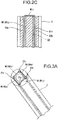
Fig. 2C is a cross-sectional view of the sheath main body of the movable catheter ofFig. 2B taken along a plane passing through the central axes of a pair of wire lumens; -
Fig. 3A is a perspective view illustrating a case where the number of wires inserted through the wire lumen of the movable catheter ofFig. 2B is increased; -
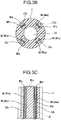
Fig. 3B is a cross-sectional view of the sheath main body of the movable catheter ofFig. 3A taken along a plane orthogonal to the central axis thereof; -
Fig. 3C is a cross-sectional view of the sheath main body of the movable catheter ofFig. 3A taken along a plane passing through the central axes of the pair of wire lumens; -
Fig. 4A is a diagram illustrating a modification example of the movable catheter ofFig. 3A ; -
Fig. 4B is a diagram illustrating another modification example of the movable catheter ofFig. 3A ; -
Fig. 4C is a diagram illustrating still another modification example of the movable catheter ofFig. 3A ; -
Fig. 5A is an enlarged perspective view illustrating a main part of a movable catheter according to another embodiment of the invention; -
Fig. 5B is a cross-sectional view of the sheath main body of the movable catheter ofFig. 5A taken along a plane orthogonal to the central axis thereof; -
Fig. 5C is a cross-sectional view of the sheath main body of the movable catheter ofFig. 5A taken along a plane passing through the central axes of a pair of wire lumens; -
Fig. 6A is an enlarged perspective view illustrating a main part of a movable catheter according to still another embodiment of the invention; -
Fig. 6B is a cross-sectional view of the sheath main body of the movable catheter ofFig. 6A taken along a plane orthogonal to the central axis thereof; -
Fig. 6C is a cross-sectional view of the sheath main body of the movable catheter ofFig. 6A taken along a plane passing through the central axes of a pair of wire lumens; -
Fig. 7 is a cross-sectional view illustrating the configuration of the sheath main body of the movable catheter according to still another embodiment of the invention; and -
Fig. 8 is a cross-sectional view illustrating the configuration of the sheath main body of the movable catheter according to still another embodiment of the invention. - Hereinafter, an embodiment of the invention will be specifically described with reference to the drawings. The catheter sheath (movable sheath) as the movable catheter of the present embodiment is a catheter that is inserted prior to an electrode catheter for detecting an electrocardiogram, an ablation catheter for cauterizing an affected area, and the like and guides the electrode catheter, the ablation catheter, and the like when, for example, catheter ablation is performed. Although the catheter sheath will be described below as an example of the movable catheter to which the invention is applied, the invention is also applicable to an electrode catheter, an ablation catheter, a movable endoscopic catheter used for X-ray contrast agent injection into a bile duct for intra-bile duct examination or the like, and other movable catheters.
- It should be noted that the catheter ablation is a treatment method for treating cardiac arrhythmia and is a treatment method by which an ablation catheter having a highfrequency electrode in its tip portion is inserted through a blood vessel into the myocardial tissue that has caused the cardiac arrhythmia, coagulative necrosis is caused by the myocardial tissue or its vicinity being cauterized at approximately 60°C to 70°C, and the arrhythmic circuit is interrupted.
- First, refer to
Figs. 1 and2A to 2C . Schematically, a catheter sheath (movable catheter) 1 is configured to include a sheath main body (tube) 2, anoperation portion 3, agrip portion 4, and a pair of wires W1 and W2. - The sheath
main body 2 is a hollow tube. Although not illustrated, a multilayer tube including a plurality of resin layers and a braid layer made of, for example, reticulated stainless steel is used as the sheathmain body 2. A part of the distal end side of the sheathmain body 2 is adeflection portion 21 capable of deflecting in any direction. Thedeflection portion 21 is set to be less rigid (more flexible) than the rest thereof. Further, in thedeflection portion 21, the rigidity is set to decrease gradually or in stages toward the tip thereof. - The material of the sheath
main body 2 is not particularly limited insofar as the material has flexibility. The material of the sheathmain body 2 is preferably a thermoplastic resin or a thermoplastic elastomer. Examples thereof include polyamide-based elastomer such as polyether block amide copolymer, polyamide, polyimide, polyamide-imide, polyethylene terephthalate, polyethylene, polypropylene, polyurethane, ethylene-vinyl acetate copolymer, polyvinyl chloride, polytetrafluoroethylene, tetrafluoroethylene-hexafluoropropylene copolymer, and tetrafluoroethylene-perfluoroalkyl vinyl ether copolymer. - An insertion hole through which the proximal end side part of the sheath
main body 2 is inserted is formed in theoperation portion 3 and thegrip portion 4 attached to the proximal end side of the sheathmain body 2. Asheath hub 41a is attached to the proximal end of thegrip portion 4. - The
sheath hub 41a has a lumen. The sheathmain body 2 in thegrip portion 4 is attached to the proximal end side of thesheath hub 41a such that the lumen of thesheath hub 41a and amain lumen 22 of the sheathmain body 2 communicate with each other. In addition, a catheter insertion port provided with a hemostatic valve is formed on the distal end side of thesheath hub 41a. When the catheter sheath 1 is used (during treatment), the above-mentioned electrode catheter and ablation catheter are inserted from the catheter insertion port of thesheath hub 41a and guided to themain lumen 22 of the sheathmain body 2 and the distal end portions thereof are guided to the myocardial tissue to be treated. In addition, a side injection tube is formed in the side portion of thesheath hub 41a and a three-way stopcock 41c is attached to the side injection tube via atube 41b. It is possible to suction blood in the body or send a liquid medicine into the body by attaching a syringe or the like to the three-way stopcock 41c. - A substantially cylindrical
tip protection member 29, which is made of resin and has a hemispherical distal end side, is provided at the distal end of the sheath main body 2 (tip of the deflection portion 21). Thetip protection member 29 has a lumen substantially equal in diameter to themain lumen 22 of the sheathmain body 2 and is integrally joined (fixed) to the distal end portion of the sheathmain body 2 by heat fusion or the like. Alternatively, thetip protection member 29 may be omitted. - In the tube wall of the sheath
main body 2, four wire lumens (sub-lumens) 23a to 23d substantially parallel to themain lumen 22 are formed so as to surround the outside of themain lumen 22. Thewire lumens 23a to 23d are formed from the proximal end portion of the sheathmain body 2 to the distal end portion of the sheathmain body 2. Thewire lumens 23a to 23d are formed outside themain lumen 22, around the central axis of the sheathmain body 2, and apart from each other at an angular pitch (angular interval) of approximately 90°. - In the present embodiment, the
wire lumens 23a to 23d are formed so as to open to the distal end surface of the sheathmain body 2 to which thetip protection member 29 is joined. Alternatively, thewire lumens 23a to 23d may be formed so as to open to the side surface of the sheathmain body 2 near the distal end surface of the sheathmain body 2 without reaching the distal end surface of the sheathmain body 2 to which thetip protection member 29 is joined. In addition, the distal end of thewire lumen 23a and the distal end of thewire lumen 23b may communicate with each other and the distal end of thewire lumen 23c and the distal end of thewire lumen 23d may communicate with each other near the distal end surface of the sheathmain body 2 without thewire lumens 23a to 23d opening to the outside of the sheathmain body 2. In this case, these communicating portions may be formed in a substantially U shape so as not to hinder the insertion of the wires W1 and W2. - The single wire W1 is inserted through the
wire lumen 23a and thewire lumen 23b, and the single wire W2 is inserted through thewire lumen 23c and thewire lumen 23d. Although the wires W1 and W2 are formed of metal such as stainless steel in the present embodiment, the wires W1 and W2 may be formed of another material such as resin. - A substantial half W1a on one end portion side of the wire W1 is inserted through the
wire lumen 23a, an intermediate part W1c thereof is folded back on the distal end surface of the sheathmain body 2 to which thetip protection member 29 is joined, a substantial half W1b on the other end portion side thereof is inserted through thewire lumen 23b, and both end portions (one end portion and the other end portion) thereof are disposed so as to be positioned in theoperation portion 3 on the proximal end side of the sheathmain body 2. Likewise, a substantial half W2a on one end portion side of the wire W2 is inserted through thewire lumen 23c, an intermediate part W2c thereof is folded back on the distal end surface of the sheathmain body 2 to which thetip protection member 29 is joined, a substantial half W2b on the other end portion side thereof is inserted through thewire lumen 23d, and both end portions (one end portion and the other end portion) thereof are disposed so as to be positioned in theoperation portion 3 on the proximal end side of the sheathmain body 2. - Both end portions of the wire W1 and both end portions of the wire W2 are pulled out from the side holes that are provided in the sheath
main body 2 in theoperation portion 3 provided on the proximal end side of the sheathmain body 2 and are connected to the operation portion 3 (a rotation operation member 31). Theoperation portion 3 has a pair of projection-shapedgrip sections portion 42 provided on the tip (distal end) side of thegrip portion 4 via a screw-type knob member 5. - In the neutral state that is illustrated in
Fig. 1 , both the wire W1 and the wire W2 are in a tensionless state (or in a state of being tense loosely and substantially evenly) and thedeflection portion 21 at the tip of the sheathmain body 2 is in a linearly extended state as illustrated inFig. 1 . - When the
rotation operation member 31 is rotated in the direction of an arrow B1 inFig. 1 by thegrip sections rotation operation member 31 being appropriately pressed from this neutral state, the wire W1 is pulled and the wire W2 is loosened as therotation operation member 31 rotates. As a result, thedeflection portion 21 at the tip is deflected as indicated by an arrow B3 inFig. 1 . - On the contrary, the wire W1 is loosened and the wire W2 is pulled when the
rotation operation member 31 is rotated in the direction of an arrow B2 inFig. 1 by thegrip sections rotation operation member 31 being appropriately pressed. As a result, thedeflection portion 21 at the tip is deflected as indicated by an arrow B4 inFig. 1 . - In a case where it is desired to fix the shape of the
deflection portion 21 with thedeflection portion 21 deflected, therotation operation member 31 is pressed by the holdingportion 42 by the knob member 5 being rotated clockwise and tightened, therotation operation member 31 is fixed at the current position, and the shape of thedeflection portion 21 is fixed. In a case where it is desired to release the fixing of the shape of the deflection portion 21 (in a case where it is desired to adjust the state of deflection), the knob member 5 is rotated counterclockwise and loosened contrary to be above, and then therotation operation member 31 is loosely pressed by the holdingportion 42 and therotation operation member 31 becomes rotatable. As a result, the fixing of the shape of thedeflection portion 21 is released and it is possible to adjust the state of deflection of thedeflection portion 21 by gripping thegrip section 32 and rotating therotation operation member 31. - In the embodiment described above, the wire W1 is folded back in the distal end portion of the
wire lumen 23a through which the substantial half W1a on one end portion side thereof is inserted and the distal end portion of thewire lumen 23b through which the substantial half W1b on the other end side thereof is inserted. Accordingly, by pulling both end portions of the wire W1 disposed on the proximal end side of the sheathmain body 2, it is possible to apply a force for deflecting the distal end portion of the sheathmain body 2 to the distal end portion of the sheathmain body 2. Accordingly, it is possible to deflect the distal end portion (deflection portion 21) of the sheathmain body 2 in accordance with the disposition of the pair ofwire lumens main body 2. The same applies to the wire W2. - Accordingly, there is no need to provide a wire fixing member such as the pointed tip and the pull ring of the related art, and thus the number of components can be reduced. In addition, there is no need to perform mounting work on a wire fixing member with respect to the catheter tube and perform wire connection work with respect to the member, and thus it is possible to reduce the number of manufacturing steps. In addition, there is no need to secure a region for providing a wire fixing member in the structure of the catheter sheath 1, and thus it is possible to reduce the structural limitation of the catheter sheath 1. For example, it is possible to increase the opening area of the distal end (tip) of the sheath main body 2 (main lumen 22).
- In addition, a force for deflecting the
deflection portion 21 is applied by both the substantial half W1a of the wire W1 inserted through thewire lumen 23a and the substantial half W1b inserted through thewire lumen 23b being pulled. Accordingly, it is possible to apply the force to a relatively wide range in the circumferential direction of the sheathmain body 2 in accordance with the interval (angular interval) between thewire lumen 23a and thewire lumen 23b. The same applies to the wire W2. As a result, the force that is applied to the wire and the risk of wire breakage that is entailed by the deflection operation are smaller than in the related art in which the deflection operation is performed by the single unfolded wire inserted through a single lumen being pulled. - Although the wire W1 and the wire W2 that are used in the embodiment described above have the same specifications such as the same wire diameter (cross-sectional area), the specifications of the wire W1 and the wire W2 may differ from each other. For example, the wire W1 may be larger in wire diameter (cross-sectional area) than the wire W2.
- In addition, although the
wire lumens 23a to 23d are arranged at an equal angular pitch (90° pitch) in the embodiment described above, thewire lumens 23a to 23d may be arranged at different angular intervals without having to be arranged at the equal angular pitch. By appropriately setting the angular intervals, it is possible to appropriately set the curvature of thedeflection portion 21 or the direction of deflection of thedeflection portion 21. - Further, although the two wires of the wire W1 inserted through the
wire lumen 23a and thewire lumen 23b and the wire W2 inserted through thewire lumen 23c and thewire lumen 23d are used in the embodiment described above, a configuration in which four wires are used with a wire W3 and a wire W4 added may be adopted as illustrated inFigs. 3A to 3C . - In other words, a substantial half W3a on one end portion side of the wire W3 is inserted through the
wire lumen 23a, an intermediate part W3c thereof is folded back on the distal end surface of the sheathmain body 2 to which thetip protection member 29 is joined, and a substantial half W3b on the other end portion side thereof is inserted through thewire lumen 23c. A substantial half W4a on one end portion side of the wire W4 is inserted through thewire lumen 23b, an intermediate part W4c thereof is folded back on the distal end surface of the sheathmain body 2 to which thetip protection member 29 is joined, and a substantial half W4b on the other end portion side thereof is inserted through thewire lumen 23d. With such a configuration, it is possible to perform deflection in four directions by appropriately selecting and pulling one of the wires W1 to W4. In addition, it is possible to deflect thedeflection portion 21 by 360° in any direction by appropriately selecting a combination of two adjacent wires from the wires W1 to W4 and adjusting the balance of the forces that respectively pull the wires. It should be noted that it is necessary to appropriately change the configuration of theoperation portion 3 in response to the addition of the wires W3 and W4, examples of which include the addition of a rotation operation member similar to therotation operation member 31 in theoperation portion 3. - In addition, although a case where the four
wire lumens 23a to 23d and the four wires W1 to W4 are provided has been described in the example illustrated inFigs. 3A to 3C , the number of wire lumens can be increased or decreased and the number of wires can be accordingly increased or decreased as illustrated in, for example,Figs. 4A to 4C . - In other words, in
Fig. 4A , sixwire lumens 24a are provided at an angular pitch of 60° and six wires W5 are provided. As a result, thedeflection portion 21 can be deflected in six directions in a case where the wires W5 are pulled one by one and it is possible to deflect thedeflection portion 21 by 360° in any direction by appropriately selecting a combination of two adjacent wires W5 and adjusting the balance of the forces that respectively pull the wires. InFig. 4B , threewire lumens 25a are provided at an angular pitch of 120° and three wires W6 are provided. As a result, thedeflection portion 21 can be deflected in three directions in a case where the wires W6 are pulled one by one and it is possible to deflect thedeflection portion 21 by 360° in any direction by appropriately selecting a combination of two adjacent wires W6 and adjusting the balance of the forces that respectively pull the wires. InFig. 4C , 24wire lumens 26a are provided at an angular pitch of 15° and 24 wires W7 are provided. As a result, thedeflection portion 21 can be deflected in 24 directions in a case where the wires W7 are pulled one by one. These are examples, the number of wire lumens may be two or more, and the number of wires may be one or more. - Although the number of wire lumens and the number of wires are equal to each other in each of the examples illustrated in
Figs. 4A to 4C , the numbers may be different from each other. For example, the number of wires may be smaller than the number of wire lumens. In addition, although both end portions of the wire are inserted through the pair of wire lumens that are adjacent to each other in each of the examples illustrated inFigs. 4A to 4C , one pair of wire lumens may be, for example, intermittently selected and both end portions of the wire may be inserted therethrough. - It should be noted that two wire lumens and one wire may be provided although this is not illustrated. Then, the
deflection portion 21 can be deflected in one direction. In this case, it is preferable that the wire lumens are disposed at an angular interval of less than 180°. Then, the distal end portion of the sheathmain body 2 can be easily deflected toward the pair of wire lumens through which the wire is inserted when both end portions of the wire are pulled at the same time. - In addition, although the substantial half W1a on one end portion side of the wire W1 and the substantial half W1b on the other end portion side of the wire W1 are inserted through the pair of
wire lumens Figs. 5A to 5C may also be adopted. In other words, inFigs. 5A to 5C , a substantial half W8a on one end portion side of a wire W8 is inserted through awire lumen 27a formed in the sheathmain body 2, an intermediate part W8c of the wire W8 is folded back at the distal end of the sheathmain body 2, a substantial half W8b on the other end portion side of the wire W8 is passed through the outside of the sheathmain body 2, and both end portions (one end portion and the other end portion) thereof are disposed on the proximal end side of the sheathmain body 2. Likewise, a substantial half W9a on one end portion side of a wire W9 is inserted through awire lumen 27b formed in the sheathmain body 2, an intermediate part W9c of the wire W9 is folded back at the distal end of the sheathmain body 2, a substantial half W9b on the other end portion side of the wire W9 is passed through the outside of the sheathmain body 2, and both end portions (one end portion and the other end portion) thereof are disposed on the proximal end side of the sheathmain body 2. According to this example illustrated inFigs. 5A to 5C , it is possible to reduce the number of wire lumens while achieving the same action and effect as the configuration illustrated inFigs. 2A to 2C . - Further, the catheter sheath may be configured as illustrated in
Figs. 6A to 6C . In other words, inFigs. 6A to 6C , a substantial half W10a on one end portion side of a wire W10 is inserted through awire lumen 28a formed in the sheathmain body 2, an intermediate part W10c of the wire W10 is folded back at the distal end of the sheathmain body 2, a substantial half W10b on the other end portion side of the wire W10 is inserted through themain lumen 22 formed in the sheathmain body 2, and both end portions (one end portion and the other end portion) thereof are disposed on the proximal end side of the sheathmain body 2. Likewise, a substantial half W11a on one end portion side of a wire W11 is inserted through awire lumen 28b formed in the sheathmain body 2, an intermediate part W11c of the wire W11 is folded back at the distal end of the sheathmain body 2, a substantial half W11b on the other end portion side of the wire W11 is inserted through themain lumen 22 formed in the sheathmain body 2, and both end portions (one end portion and the other end portion) thereof are disposed on the proximal end side of the sheathmain body 2. Also with this example illustrated inFigs. 6A to 6C , it is possible to reduce the number of wire lumens while achieving the same action and effect as the configuration illustrated inFigs. 2A to 2C . - Further, although a plurality of wire lumens formed in the tube wall of the sheath
main body 2 having themain lumen 22 have been exemplified in the embodiment described above, a single-lumen tube 200 having amain lumen 200a and at least onemulti-lumen tube 201 having a plurality ofwire lumens Fig. 7 . - In the example illustrated in
Fig. 7 , fourmulti-lumen tubes 201 are disposed around the single-lumen tube 200, which has a substantially circular cross section and themain lumen 200a. Themulti-lumen tube 201 has a substantially elliptical cross section and the pair ofwire lumens wire lumen 201a, and a substantial half W12b on the other end portion side of wire W12 is inserted through thewire lumen 201b. The single-lumen tube 200 and themulti-lumen tube 201 can be integrated with each other by, for example, adhesion by means of an adhesive or heat welding. Although it is not always easy to manufacture what has a plurality of wire lumens formed in the tube wall of the sheathmain body 2 having themain lumen 22, it is possible to improve productivity by combining and integrating a plurality of tubes as described above. - Further, although the sheath main body is configured by the single-
lumen tube 200 and themulti-lumen tube 201 being combined and integrated in the embodiment illustrated inFig. 7 , a single-lumen tube 202 having amain lumen 202a and a plurality oflong members 203 may be combined and integrated, as illustrated inFig. 8 and such that a gap is formed between the single-lumen tube 202 and thelong member 203, to be used as the sheath main body. In this case, the gap may be used aswire lumens - In the example illustrated in
Fig. 8 , four solidlong members 203 are disposed around the single-lumen tube 202, which has a substantially circular cross section and themain lumen 202a. Thelong member 203 has a substantially elliptical cross section. Four gaps are formed between the single-lumen tube 202 and twolong members 203, each of the gaps has a substantially triangular cross section, and the four gaps are used as two pairs ofwire lumens wire lumen 204a, and a substantial half W13b on the other end portion side of the wire W13 is inserted through thewire lumen 204b. The single-lumen tube 202 and thelong member 203 can be integrated with each other by, for example, adhesion by means of an adhesive or heat welding. In this embodiment, no multi-lumen tube is necessary, and thus the productivity can be further improved. - The embodiments described above have been described so that the understanding of the invention is facilitated and do not limit the invention. Accordingly, each element disclosed in the embodiments described above is intended to include every change in design and equivalent within the technical scope of the invention.
-
- 1 CATHETER SHEATH (MOVABLE CATHETER)
- 2 SHEATH MAIN BODY (TUBE)
- 21 DEFLECTION PORTION
- 22, 200a, 202aMAIN LUMEN
- 23a to 23d, 24a, 25a, 26a, 27a, 27b, 28a, 28b, 201a, 201b, 204a, 204b WIRE LUMEN
- 29 TIP PROTECTION MEMBER
- 200, 202 SINGLE-LUMEN TUBE
- 201 MULTI-LUMEN TUBE
- 203 LONG MEMBER
- 3 OPERATION PORTION
- 31 ROTATION OPERATION MEMBER
- 32 GRIP SECTION
- 4 GRIP PORTION
- 42 HOLDING PORTION
- 5 KNOB MEMBER
- W1 TO W13 WIRE
Claims (5)
- A movable catheter provided with a tube having a main lumen, wherein
the tube has a plurality of wire lumens outside the main lumen, and the plurality of wire lumens are spaced apart from each other and reach a distal end portion of the tube from a proximal end portion of the tube, and
the tube includes at least one wire, a substantial half of the wire at one end portion side of the wire is inserted through one of the wire lumens, an intermediate part of the wire is folded back on the distal end portion of the tube, a substantial half of the wire at the other end portion side of the wire is inserted through another one of the wire lumens, and the one end portion and the other end portion of the wire are disposed at the proximal end side of the tube. - The movable catheter according to claim 1, wherein the wire lumens comprise three or more wire lumens and the movable catheter comprises two or more wires.
- The movable catheter according to claim 1 or 2, wherein the tube has a single-lumen tube having the main lumen and at least one multi-lumen tube integrally disposed outside the single-lumen tube and having a plurality of the wire lumens.
- A movable catheter provided with a tube having a main lumen, wherein
the tube has a wire lumen outside the main lumen, and the wire lumen reaches a distal end portion of the tube from a proximal end portion of the tube, and
the tube includes a wire, a substantial half of the wire at one end portion side of the wire is inserted through the wire lumen, an intermediate part of the wire is folded back on the distal end portion of the tube, a substantial half of the wire at the other end portion side of the wire is passed over an outside of the tube, and the one end portion and the other end portion of the wire are disposed at the proximal end side of the tube. - A movable catheter provided with a tube having a main lumen, wherein
the tube has a wire lumen outside the main lumen, and the wire lumen reaches a distal end portion of the tube from a proximal end portion of the tube, and
the tube includes a wire, a substantial half of the wire at one end portion side of the wire is inserted through the wire lumen, an intermediate part of the wire is folded back on the distal end portion of the tube, a substantial half of the wire of the other end portion side of the wire is inserted through the main lumen, and the one end portion and the other end portion of the wire are disposed at the proximal end side of the tube.
Applications Claiming Priority (2)
| Application Number | Priority Date | Filing Date | Title |
|---|---|---|---|
| JP2018078540 | 2018-04-16 | ||
| PCT/JP2019/015447 WO2019203061A1 (en) | 2018-04-16 | 2019-04-09 | Movable catheter |
Publications (2)
| Publication Number | Publication Date |
|---|---|
| EP3782691A1 true EP3782691A1 (en) | 2021-02-24 |
| EP3782691A4 EP3782691A4 (en) | 2022-01-26 |
Family
ID=68239164
Family Applications (1)
| Application Number | Title | Priority Date | Filing Date |
|---|---|---|---|
| EP19787582.6A Pending EP3782691A4 (en) | 2018-04-16 | 2019-04-09 | MOBILE CATHETER |
Country Status (5)
| Country | Link |
|---|---|
| US (1) | US20210146096A1 (en) |
| EP (1) | EP3782691A4 (en) |
| JP (1) | JP7664578B2 (en) |
| CN (2) | CN117717695A (en) |
| WO (1) | WO2019203061A1 (en) |
Families Citing this family (8)
| Publication number | Priority date | Publication date | Assignee | Title |
|---|---|---|---|---|
| EP3628208A1 (en) * | 2018-09-28 | 2020-04-01 | Ambu A/S | An articulated tip part for an endoscope |
| EP3636133B1 (en) | 2018-10-12 | 2024-04-03 | Ambu A/S | An articulated tip part for an endoscope |
| DE102019121038A1 (en) * | 2019-08-05 | 2021-02-11 | Karl Storz Se & Co. Kg | Endoscopic device |
| WO2021200998A1 (en) * | 2020-03-30 | 2021-10-07 | 国立大学法人滋賀医科大学 | Flange hub, long and narrow body, and implement |
| WO2021216411A1 (en) * | 2020-04-20 | 2021-10-28 | Enlight Medical Technologies (Shanghai) Co., Ltd. | Catheter with electrically-actuated articulation |
| EP4035584B1 (en) | 2021-01-28 | 2023-10-18 | Ambu A/S | Endoscope comprising an articulated bending section body |
| CN113974530B (en) * | 2021-12-07 | 2025-04-29 | 广州瑞派医疗器械有限责任公司 | Endoscopic snake bone and endoscope |
| CN119405246B (en) * | 2025-01-03 | 2025-05-16 | 湖南省华芯医疗器械有限公司 | A traction rope distal end fixing structure and endoscope |
Family Cites Families (19)
| Publication number | Priority date | Publication date | Assignee | Title |
|---|---|---|---|---|
| US3625200A (en) * | 1969-08-26 | 1971-12-07 | Us Catheter & Instr Corp | Controlled curvable tip member |
| JPH0397428A (en) * | 1989-09-12 | 1991-04-23 | Olympus Optical Co Ltd | Curving operation device for tubular fitting tool |
| JP2502199Y2 (en) * | 1990-08-08 | 1996-06-19 | オリンパス光学工業株式会社 | Medical tube |
| JPH05285089A (en) * | 1992-04-10 | 1993-11-02 | Olympus Optical Co Ltd | Bending mechanism for flexible pipe |
| JPH0966109A (en) * | 1995-09-04 | 1997-03-11 | Olympus Optical Co Ltd | Medical tube |
| JP3845147B2 (en) * | 1996-07-25 | 2006-11-15 | オリンパス株式会社 | Flexible tube |
| JP4231568B2 (en) * | 1998-03-20 | 2009-03-04 | オリンパス株式会社 | Tubular insert |
| US8287554B2 (en) * | 1999-06-22 | 2012-10-16 | Ethicon Endo-Surgery, Inc. | Method and devices for tissue reconfiguration |
| JP2002272675A (en) | 2001-03-16 | 2002-09-24 | Olympus Optical Co Ltd | Catheter |
| US6524302B2 (en) * | 2001-04-26 | 2003-02-25 | Scimed Life Systems, Inc. | Multi-lumen catheter |
| US7594903B2 (en) * | 2002-09-25 | 2009-09-29 | Abbott Cardiovascular Systems Inc. | Controlling shaft bending moment and whipping in a tendon deflection or other tendon system |
| US8500675B2 (en) * | 2005-01-20 | 2013-08-06 | M. Samy Ahmed Hamboly | Multilumen catheter with pressure resistant lumen and method |
| DE102009037827A1 (en) * | 2009-08-10 | 2011-02-17 | Epflex Feinwerktechnik Gmbh | Medical catheter instrument |
| JP5614848B2 (en) * | 2011-07-12 | 2014-10-29 | 日本ライフライン株式会社 | Catheter handle |
| TWI488663B (en) * | 2011-12-13 | 2015-06-21 | Bioteque Corp | Method for manufacturing multi-lumen tube |
| JP2014018391A (en) * | 2012-07-18 | 2014-02-03 | Sumitomo Bakelite Co Ltd | Catheter |
| JP2014188039A (en) | 2013-03-26 | 2014-10-06 | Nippon Zeon Co Ltd | Steerable catheter |
| JP6554794B2 (en) * | 2014-01-29 | 2019-08-07 | 住友ベークライト株式会社 | Medical equipment |
| US10376673B2 (en) * | 2015-06-19 | 2019-08-13 | Evalve, Inc. | Catheter guiding system and methods |
-
2019
- 2019-04-09 WO PCT/JP2019/015447 patent/WO2019203061A1/en not_active Ceased
- 2019-04-09 US US17/048,061 patent/US20210146096A1/en active Pending
- 2019-04-09 CN CN202311662969.0A patent/CN117717695A/en active Pending
- 2019-04-09 CN CN201980024597.4A patent/CN112118885A/en active Pending
- 2019-04-09 EP EP19787582.6A patent/EP3782691A4/en active Pending
- 2019-04-09 JP JP2020514093A patent/JP7664578B2/en active Active
Also Published As
| Publication number | Publication date |
|---|---|
| JP7664578B2 (en) | 2025-04-18 |
| US20210146096A1 (en) | 2021-05-20 |
| CN117717695A (en) | 2024-03-19 |
| CN112118885A (en) | 2020-12-22 |
| EP3782691A4 (en) | 2022-01-26 |
| WO2019203061A1 (en) | 2019-10-24 |
| JPWO2019203061A1 (en) | 2021-04-22 |
Similar Documents
| Publication | Publication Date | Title |
|---|---|---|
| EP3782691A1 (en) | Movable catheter | |
| EP3943139B1 (en) | Steerable catheter | |
| JP5734562B2 (en) | A deflectable sheath guidance device | |
| US9498602B2 (en) | Guided intravascular catheter sheath having bi-directional steering assembly | |
| US5782900A (en) | Catheter system having safety means | |
| US5891027A (en) | Cardiovascular catheter system with an inflatable soft tip | |
| CN115645036B (en) | Pulse ablation device | |
| US20020072710A1 (en) | Medical device delivery catheter with distal locator | |
| JP2005523125A (en) | Method and system for delivering a medical electrical lead into the venous system | |
| US10737067B2 (en) | Guiding catheter for renal artery and method for using the same | |
| EP4144397B1 (en) | Steerable sheath and catheter with circular deflection | |
| EP3949884A1 (en) | Medical device | |
| WO2023142428A1 (en) | Splined basket ablation catheter capable of being bent bidirectionally | |
| US11986157B2 (en) | Braking mechanisms for steerable medical devices and related methods | |
| JP7523073B2 (en) | Steerable Catheter | |
| CN116764068B (en) | Adjustable curved catheter for interventional type | |
| US20230029648A1 (en) | Planar end effector with irrigation | |
| JP7663113B2 (en) | Nodal ring structure and steerable catheter | |
| WO2023007324A1 (en) | Planar end effector with irrigation | |
| US20230329782A1 (en) | Catheter | |
| US20250009418A1 (en) | Catheter | |
| WO2025178013A1 (en) | Electrode catheter |
Legal Events
| Date | Code | Title | Description |
|---|---|---|---|
| STAA | Information on the status of an ep patent application or granted ep patent |
Free format text: STATUS: THE INTERNATIONAL PUBLICATION HAS BEEN MADE |
|
| PUAI | Public reference made under article 153(3) epc to a published international application that has entered the european phase |
Free format text: ORIGINAL CODE: 0009012 |
|
| STAA | Information on the status of an ep patent application or granted ep patent |
Free format text: STATUS: REQUEST FOR EXAMINATION WAS MADE |
|
| 17P | Request for examination filed |
Effective date: 20201015 |
|
| AK | Designated contracting states |
Kind code of ref document: A1 Designated state(s): AL AT BE BG CH CY CZ DE DK EE ES FI FR GB GR HR HU IE IS IT LI LT LU LV MC MK MT NL NO PL PT RO RS SE SI SK SM TR |
|
| AX | Request for extension of the european patent |
Extension state: BA ME |
|
| DAV | Request for validation of the european patent (deleted) | ||
| DAX | Request for extension of the european patent (deleted) | ||
| REG | Reference to a national code |
Ref country code: DE Ref legal event code: R079 Free format text: PREVIOUS MAIN CLASS: A61M0025092000 Ipc: A61M0025010000 |
|
| A4 | Supplementary search report drawn up and despatched |
Effective date: 20211223 |
|
| RIC1 | Information provided on ipc code assigned before grant |
Ipc: A61M 25/01 20060101AFI20211220BHEP |
|
| STAA | Information on the status of an ep patent application or granted ep patent |
Free format text: STATUS: EXAMINATION IS IN PROGRESS |
|
| 17Q | First examination report despatched |
Effective date: 20250312 |
|
| GRAP | Despatch of communication of intention to grant a patent |
Free format text: ORIGINAL CODE: EPIDOSNIGR1 |
|
| STAA | Information on the status of an ep patent application or granted ep patent |
Free format text: STATUS: GRANT OF PATENT IS INTENDED |