EP3782527A1 - Dishwasher - Google Patents
Dishwasher Download PDFInfo
- Publication number
- EP3782527A1 EP3782527A1 EP18915517.9A EP18915517A EP3782527A1 EP 3782527 A1 EP3782527 A1 EP 3782527A1 EP 18915517 A EP18915517 A EP 18915517A EP 3782527 A1 EP3782527 A1 EP 3782527A1
- Authority
- EP
- European Patent Office
- Prior art keywords
- dish rack
- adjustment
- triggering member
- adjustment support
- dishwasher
- Prior art date
- Legal status (The legal status is an assumption and is not a legal conclusion. Google has not performed a legal analysis and makes no representation as to the accuracy of the status listed.)
- Withdrawn
Links
- 230000009471 action Effects 0.000 claims abstract description 5
- XEEYBQQBJWHFJM-UHFFFAOYSA-N Iron Chemical compound [Fe] XEEYBQQBJWHFJM-UHFFFAOYSA-N 0.000 claims description 22
- 229910052742 iron Inorganic materials 0.000 claims description 11
- 238000003825 pressing Methods 0.000 claims description 4
- 230000005484 gravity Effects 0.000 abstract description 3
- 238000004519 manufacturing process Methods 0.000 abstract description 2
- 238000010586 diagram Methods 0.000 description 5
- 230000007246 mechanism Effects 0.000 description 3
- 238000003754 machining Methods 0.000 description 2
- 238000012986 modification Methods 0.000 description 2
- 230000004048 modification Effects 0.000 description 2
- 238000005406 washing Methods 0.000 description 2
- 101150114468 TUB1 gene Proteins 0.000 description 1
- 238000005452 bending Methods 0.000 description 1
- 238000004891 communication Methods 0.000 description 1
- 230000007547 defect Effects 0.000 description 1
- 230000000694 effects Effects 0.000 description 1
- 230000010354 integration Effects 0.000 description 1
- 230000007704 transition Effects 0.000 description 1
Images


Classifications
-
- A—HUMAN NECESSITIES
- A47—FURNITURE; DOMESTIC ARTICLES OR APPLIANCES; COFFEE MILLS; SPICE MILLS; SUCTION CLEANERS IN GENERAL
- A47L—DOMESTIC WASHING OR CLEANING; SUCTION CLEANERS IN GENERAL
- A47L15/00—Washing or rinsing machines for crockery or tableware
- A47L15/42—Details
- A47L15/50—Racks ; Baskets
- A47L15/504—Arrangements for changing the height of racks
-
- A—HUMAN NECESSITIES
- A47—FURNITURE; DOMESTIC ARTICLES OR APPLIANCES; COFFEE MILLS; SPICE MILLS; SUCTION CLEANERS IN GENERAL
- A47L—DOMESTIC WASHING OR CLEANING; SUCTION CLEANERS IN GENERAL
- A47L15/00—Washing or rinsing machines for crockery or tableware
- A47L15/42—Details
- A47L15/50—Racks ; Baskets
- A47L15/507—Arrangements for extracting racks, e.g. roller supports
Definitions
- the invention relates to a technical field of dishwashers, and in particular to a height adjustment mechanism for the dishwasher and the dishwasher with the height adjustment mechanism.
- a dishwasher is a device of automatically washing a bowl, chopsticks, a plate, a dish, a knife, a fork and other tableware.
- the dishwasher includes a housing, a inner tub disposed in the housing and a dish rack connected with the inner tub.
- the used tableware such as the bowl and the plate, is placed on the dish rack, for washing.
- the big tableware is in contact with a top of the inner tub. At the moment, the dish rack needs to be moved downwards. At the moment, if the dish rack is fixed on the inner tub, it is difficult to clean the big tableware.
- a Chinese Patent Literature CN106691350A discloses an adjustment structure for a dish rack of a dishwasher.
- the dish rack is provided with a handle, the handle is provided with a locating member, and an inner wall of a cavity of the dishwasher is connected with a locating screw rod.
- the locating screw rod is presented as a zigzag.
- the handle drives the locating member under an action of a spring to rotate toward an inner part of the locating member, and the locating member moves to an inner part of the locating screw rod.
- the locating member supports the locating screw rod, as to prevent the locating screw rod from falling.
- the handle drives the locating member to rotate to a position far away from the locating screw rod. Since the locating screw rod is not limited, the dish rack falls in presence of gravity. In this way, movement from the high position to the low position is completed.
- the locating screw rod in order to realize location of a right side and a left side with the locating screw rod, the locating screw rod needs to be bent as the zigzag and other shapes, and a machining process is complicated. Meanwhile, when the dish rack moves from the low position to the high position, the locating member is always pushed upwards by the locating screw rod and extruded downwards by the spring. At the moment, the locating member easily moves relative to the locating screw rod. Once the locating member is separated from the locating screw rod, the dish rack does not move to the high position any longer.
- the technical problem to be solved in the invention is to overcome a defect that a height adjustment mechanism of a dish rack in the art known to inventors has complicated machining and is easily trapped in a failure.
- a dishwasher including an inner tub, a dish rack, an adjustment piece, an adjustment support and a triggering member.
- the inner tub has an accommodating cavity for containing the dish rack.
- the dish rack moves between a high position and a low position relative to the inner tub.
- the adjustment piece is fixed on the inner tub, and the adjustment piece has a limiting end.
- the adjustment support is fixed on the dish rack, and the adjustment support has a sliding groove allowing the limiting end to be embedded.
- the sliding groove has a first limiting point corresponding to the high position of the dish rack, and a second limiting point corresponding to the low position of the dish rack.
- the triggering member is rotatably disposed on the adjustment support.
- the triggering member has a first status of abutting against a position above the limiting end of the adjustment piece when the adjustment support is located at the first limiting point of the sliding groove, as to keep the dish rack at the high position, and a second status of rotating and departing from the limiting end to make the adjustment support move toward the low position, so that the limiting end is in contact with the second limiting point.
- the adjustment support includes: a main body and a vertical mounting groove.
- the vertical mounting groove is connected with the main body, and the vertical mounting groove is arranged to embed into the dish rack.
- the main body and the vertical mounting groove are disposed on two sides of the triggering member.
- the main body is provided with a limiting groove for accommodating a rotary shaft.
- the triggering member is connected with the rotary shaft through a torsional spring. When the dish rack moves to the high position from the low position, the torsional spring is disposed to provide thrust force making the triggering member rotate to the position above the limiting end.
- the adjustment support further includes a horizontal mounting groove disposed on the main body.
- the horizontal mounting groove is embedded into a horizontal position of the dish rack.
- the horizontal mounting groove and the vertical mounting groove are provided with a reverse buckle respectively.
- the reverse buckle is arranged to clamp a bracket mounting groove on an iron wire of the dish rack.
- the triggering member is an adjustment handle
- the handle includes a propping portion that is in contact with the limiting end of the adjustment support, and a pressing portion to which external force is applied.
- the propping portion is provided with a limiting structure.
- the limiting structure When the triggering member rotates under an action of the torsional spring, the limiting structure is able to be in contact with the main body of the adjustment support, as to prevent the propping portion from undue rotation.
- a side of the adjustment piece far away from the limiting end is provided with a plurality of buckles distributed along a vertical direction, and the adjustment piece is connected with the dish rack through the plurality of buckles.
- a side of the adjustment piece far away from the dish rack is provided with a plurality of rollers.
- the rollers are divided along a vertical direction, including a first roller group disposed at an upper part and a second roller group disposed at a lower part.
- Two horizontal beams are oppositely provided on the inner tub. Each of the two horizontal beams is disposed between the first roller group and the second roller group in a clamping manner.
- the dish rack is able to move horizontally in the accommodating cavity under a limitation of the two horizontal beams.
- orientation or position relationships indicated by terms “center”, “upper”, “lower”, “left”, “right”, “vertical”, “horizontal”, “inner”, “outer” and the like are orientation or position relationships shown in the drawings and are adopted not to indicate or imply that indicated devices or components must be in specific orientations or structured and operated in specific orientations but only to conveniently describe the invention and simplify descriptions and thus should not be understood as limits to the invention.
- terms “first”, “second” and “third” are only adopted for description and should not be understood to indicate or imply relative importance.
- mount In the descriptions of the invention, it is to be noted that, unless otherwise definitely specified and limited, terms “mount”, “mutually connect” and “connect” should be broadly understood.
- the terms refer to fixed connection and may also refer to detachable connection or integration.
- the terms may refer to mechanical connection and may also refer to electrical connection.
- the terms may refer to direct mutual connection, may also refer to indirect connection through a medium and may refer to communication in two components.
- specific meanings of these terms in the invention are understood according to a specific condition.
- an inner tub 1 is provided with an accommodating cavity for containing a dish rack, and the dish rack 2 moves between a high position and a low position relative to the inner tub.
- an adjustment piece 3 is fixed on the inner tub, and the adjustment piece is provided with a limiting end.
- An adjustment support 4 is fixed on the dish rack, and the adjustment support has a sliding groove 411 allowing the limiting end to be embedded.
- the sliding groove has a first limiting point A corresponding to the high position of the dish rack and a second limiting point B corresponding to the low position of the dish rack.
- a triggering member 5 is rotatably disposed on the adjustment support, and the triggering member 5 has a first status (shown in Fig. 4 ) of propping against a position above the limiting end of the adjustment piece when the adjustment support is located at the first limiting point A of the sliding groove, as to keep the dish rack at the high position, and a second status (shown in Fig. 5 ) of rotating under an external force and departing from the limiting end to make the adjustment support move toward the low position, so that the limiting end is in contact with the second limiting point B.
- the adjustment support includes: a main body and a vertical mounting groove 42.
- the vertical mounting groove 42 is connected with the main body, and the bracket mounting groove is disposed to embed into the dish rack.
- the main body and the bracket mounting groove are disposed on two sides of the triggering member 5.
- the adjustment support further includes a horizontal mounting groove 44 disposed on the main body. When the adjustment support is mounted on the dish rack, the horizontal mounting groove 44 is embedded into a horizontal position of the dish rack.
- the dish rack is formed by bending an iron wire.
- the iron wire when bent, forms an iron wire extending along a horizontal direction and an iron wire extending along a vertical direction.
- the vertical mounting groove 42 will be embedded into the iron wire extending along the vertical direction
- the horizontal mounting groove 44 will be embedded into the iron wire extending along the horizontal direction.
- the horizontal mounting groove 44 and the vertical mounting groove 42 are provided with reserve buckles, and the reverse buckles are arranged to clamp the bracket mounting groove on the iron wire of the dish rack.
- a side of the adjustment piece far away from the limiting end is provided with a plurality of buckles that are arranged along a vertical direction. As shown in Fig. 4 , the buckles are embedded into a first iron wire 11, in this way the adjustment piece is connected with the dish rack.
- the main body is provided with a limiting groove 43 arranged to accommodate a rotary shaft.
- the triggering member 5 is connected with the rotary shaft through a torsional spring 6.
- the torsional spring 6 is disposed to provide thrust force making the triggering member 5 rotate to the position above the limiting end.
- one end of the torsional spring 6 is propped against the main body, and another end is propped against the triggering member 5.
- the torsional spring 6 applies certain restoring force to the triggering member 5.
- the triggering member 5 is an adjustment handle. As shown in Fig. 2 , the adjustment handle includes a propping portion that is in contact with the limiting end of the adjustment support and a pressing portion to which external force is applied.
- a lower end of the propping portion is kept in touch with a top surface of the limiting end.
- the propping portion is provided with a limiting structure.
- the triggering member 5 rotates under an action of the torsional spring 6, the limiting structure is in contact with the main body of the adjustment support, as to prevent the propping portion from undue rotation.
- a side of the adjustment piece far away from the dish rack is provided with a plurality of rollers.
- the rollers are divided along a vertical direction, the rollers includes a first roller group disposed at an upper part and a second roller group disposed at a lower part.
- Two horizontal beams are oppositely provided on the inner tub. The horizontal beams are disposed between the first roller group and the second roller group in a clamping manner.
- the dish rack moves horizontally in the accommodating cavity under a limitation of the horizontal beams.
- the first roller group and the second roller group extend along an identical straight line respectively.
- the first roller group and the second roller group are clamped on an upper side and a lower side of each of the horizontal beams.
- the first roller group and the second roller group rotate relative to the each of the horizontal beams.
Landscapes
- Washing And Drying Of Tableware (AREA)
Abstract
Description
- The invention claims priority to Chinese Patent Application No.
201810355837.6, filed on April 19, 2018 - The invention relates to a technical field of dishwashers, and in particular to a height adjustment mechanism for the dishwasher and the dishwasher with the height adjustment mechanism.
- A dishwasher is a device of automatically washing a bowl, chopsticks, a plate, a dish, a knife, a fork and other tableware. The dishwasher includes a housing, a inner tub disposed in the housing and a dish rack connected with the inner tub. The used tableware, such as the bowl and the plate, is placed on the dish rack, for washing.
- However, when a user places non-standard big tableware on the dish rack, the big tableware is in contact with a top of the inner tub. At the moment, the dish rack needs to be moved downwards. At the moment, if the dish rack is fixed on the inner tub, it is difficult to clean the big tableware.
- Thus, a Chinese Patent Literature
CN106691350A discloses an adjustment structure for a dish rack of a dishwasher. The dish rack is provided with a handle, the handle is provided with a locating member, and an inner wall of a cavity of the dishwasher is connected with a locating screw rod. The locating screw rod is presented as a zigzag. When the dish rack needs to be located at a relatively high position (high position) of the cavity of the dishwasher, the dish rack is pushed to move upwards, the locating screw rod pushes the locating member first to rotate until the locating screw rod rotates to the high position at which the locating screw rod needs to stop. The handle drives the locating member under an action of a spring to rotate toward an inner part of the locating member, and the locating member moves to an inner part of the locating screw rod. At the moment, the locating member supports the locating screw rod, as to prevent the locating screw rod from falling. When the big tableware needs to be placed into the dishwasher, that is, the dish rack is located at a relatively low position (low position) of the cavity of the dishwasher, the user manually rotates the handle. At the moment, the handle drives the locating member to rotate to a position far away from the locating screw rod. Since the locating screw rod is not limited, the dish rack falls in presence of gravity. In this way, movement from the high position to the low position is completed. - However, in the abovementioned literature, in order to realize location of a right side and a left side with the locating screw rod, the locating screw rod needs to be bent as the zigzag and other shapes, and a machining process is complicated. Meanwhile, when the dish rack moves from the low position to the high position, the locating member is always pushed upwards by the locating screw rod and extruded downwards by the spring. At the moment, the locating member easily moves relative to the locating screw rod. Once the locating member is separated from the locating screw rod, the dish rack does not move to the high position any longer.
- Therefore, the technical problem to be solved in the invention is to overcome a defect that a height adjustment mechanism of a dish rack in the art known to inventors has complicated machining and is easily trapped in a failure.
- To this end, some embodiments of the invention provide a dishwasher, including an inner tub, a dish rack, an adjustment piece, an adjustment support and a triggering member. The inner tub has an accommodating cavity for containing the dish rack. The dish rack moves between a high position and a low position relative to the inner tub. The adjustment piece is fixed on the inner tub, and the adjustment piece has a limiting end. The adjustment support is fixed on the dish rack, and the adjustment support has a sliding groove allowing the limiting end to be embedded. The sliding groove has a first limiting point corresponding to the high position of the dish rack, and a second limiting point corresponding to the low position of the dish rack. The triggering member is rotatably disposed on the adjustment support. The triggering member has a first status of abutting against a position above the limiting end of the adjustment piece when the adjustment support is located at the first limiting point of the sliding groove, as to keep the dish rack at the high position, and a second status of rotating and departing from the limiting end to make the adjustment support move toward the low position, so that the limiting end is in contact with the second limiting point.
- In some embodiments, the adjustment support includes: a main body and a vertical mounting groove. The vertical mounting groove is connected with the main body, and the vertical mounting groove is arranged to embed into the dish rack. When the triggering member is mounted on the adjustment support, the main body and the vertical mounting groove are disposed on two sides of the triggering member.
- In some embodiments, the main body is provided with a limiting groove for accommodating a rotary shaft. The triggering member is connected with the rotary shaft through a torsional spring. When the dish rack moves to the high position from the low position, the torsional spring is disposed to provide thrust force making the triggering member rotate to the position above the limiting end.
- In some embodiments, the adjustment support further includes a horizontal mounting groove disposed on the main body. When the adjustment support is mounted on the dish rack, the horizontal mounting groove is embedded into a horizontal position of the dish rack.
- In some embodiments, the horizontal mounting groove and the vertical mounting groove are provided with a reverse buckle respectively. The reverse buckle is arranged to clamp a bracket mounting groove on an iron wire of the dish rack.
- In some embodiments, the triggering member is an adjustment handle, and the handle includes a propping portion that is in contact with the limiting end of the adjustment support, and a pressing portion to which external force is applied.
- In some embodiments, the propping portion is provided with a limiting structure. When the triggering member rotates under an action of the torsional spring, the limiting structure is able to be in contact with the main body of the adjustment support, as to prevent the propping portion from undue rotation.
- In some embodiments, a side of the adjustment piece far away from the limiting end is provided with a plurality of buckles distributed along a vertical direction, and the adjustment piece is connected with the dish rack through the plurality of buckles.
- In some embodiments, a side of the adjustment piece far away from the dish rack is provided with a plurality of rollers. The rollers are divided along a vertical direction, including a first roller group disposed at an upper part and a second roller group disposed at a lower part. Two horizontal beams are oppositely provided on the inner tub. Each of the two horizontal beams is disposed between the first roller group and the second roller group in a clamping manner. The dish rack is able to move horizontally in the accommodating cavity under a limitation of the two horizontal beams.
- The technical solution of some embodiments of the invention has the following advantages.
- 1. Some embodiments of the invention provide the dishwasher. Adjustment of the dish rack between the high position and the lower position is completed in presence of the triggering member, the adjustment piece and the adjustment support. The adjustment support and the dish rack move synchronously, the adjustment support is connected with the triggering member, the triggering member plays a role of switching, and the adjustment piece itself is fixed. When the dish rack is located at the high position, the triggering member is propped against the limiting end of the adjustment piece. At the moment, the dish rack driven with the adjustment support is located at the high position as well relative to the adjustment piece. When the dish rack needs to be lowered to the low position from the high position, the triggering member needs to rotate only. At the moment, the triggering member is departed from the limiting end. Since the dish rack is located at the relatively high position, the dish rack drives the adjustment support and the triggering member to fall under its own gravity at the moment.
In some embodiments of the invention, the limiting end of the adjustment piece is always embedded into the sliding groove, so that movement of the adjustment support in a vertical direction is kept stable, and accordingly the stability of movement of the dish rack is improved.
Meanwhile, as a transition piece, the adjustment support is simple in structure and easy to manufacture, and the sliding groove is provided on the adjustment support, accordingly the adjustment piece is stabilized. - 2. Some embodiments of the invention provide the dishwasher, the two sides of the triggering member are limited, thus such a disposing mode greatly improves the stability of the triggering member during rotation. In this way, the triggering member is effectively prevented from shaking relative to the limiting end of the adjustment piece, and a failure in limitation of the adjustment piece is prevented.
- In order to describe the technical solution in a specific embodiment or the conventional art of the invention more clearly, the drawings required to be used in the specific embodiment or the conventional art will be simply introduced below. It is apparent that the drawings in the following descriptions are only some embodiments of the invention, and those of ordinary skill in the art further obtains other drawings according to these drawings without creative work.
-
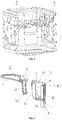
Fig. 1 is a schematic diagram of assembling between a dish rack and a horizontal beam provided by the invention. -
Fig. 2 is a schematic diagram of assembling between an adjustment support and a triggering member provided by the invention. -
Fig. 3 is a structure diagram of an adjustment piece provided by the invention. -
Fig. 4 is a schematic diagram when a dish rack in a dishwasher provided by the invention is located at a high position. -
Fig. 5 is a schematic diagram when a dish rack in a dishwasher provided by the invention is located at a lower position. - 1-Inner tub; 2-Dish rack; 3-Adjustment piece; 31-Limiting end; 32-buckle; 4-Adjustment support; 41-Main body; 411-Sliding groove; 42-Vertical mounting groove; 43-Limiting groove; 44-Horizontal mounting groove; A-First limiting point; B-Second limiting point; 5-Triggering element; 51-Propping portion; 511-Limiting structure; 52-Pressing portion; 6-Torsional spring; 7-Horizontal beam; 8-First roller group; 9-Second roller group; 10-Reverse buckle; and 11-First iron wire.
- The technical solution of the invention will be clearly and completely described below in combination with the drawings. It is apparent that the described embodiments are not all embodiments but part of embodiments of the invention. All other embodiments obtained by those of ordinary skill in the art on the basis of the embodiments in the invention without creative work shall fall within the scope of protection of the invention.
- In the descriptions of the invention, it is to be noted that orientation or position relationships indicated by terms "center", "upper", "lower", "left", "right", "vertical", "horizontal", "inner", "outer" and the like are orientation or position relationships shown in the drawings and are adopted not to indicate or imply that indicated devices or components must be in specific orientations or structured and operated in specific orientations but only to conveniently describe the invention and simplify descriptions and thus should not be understood as limits to the invention. In addition, terms "first", "second" and "third" are only adopted for description and should not be understood to indicate or imply relative importance.
- In the descriptions of the invention, it is to be noted that, unless otherwise definitely specified and limited, terms "mount", "mutually connect" and "connect" should be broadly understood. For example, the terms refer to fixed connection and may also refer to detachable connection or integration. The terms may refer to mechanical connection and may also refer to electrical connection. The terms may refer to direct mutual connection, may also refer to indirect connection through a medium and may refer to communication in two components. For those of ordinary skill in the art, specific meanings of these terms in the invention are understood according to a specific condition.
- In addition, the technical features involved in different embodiments of the invention described below are combined without conflicts.
- Some embodiments provide a dishwasher. As shown in
Fig. 1 , aninner tub 1 is provided with an accommodating cavity for containing a dish rack, and thedish rack 2 moves between a high position and a low position relative to the inner tub. - As shown in
Fig. 3 , anadjustment piece 3 is fixed on the inner tub, and the adjustment piece is provided with a limiting end. An adjustment support 4 is fixed on the dish rack, and the adjustment support has a slidinggroove 411 allowing the limiting end to be embedded. As shown inFig. 2 , the sliding groove has a first limiting point A corresponding to the high position of the dish rack and a second limiting point B corresponding to the low position of the dish rack. - In some embodiments, a triggering member 5 is rotatably disposed on the adjustment support, and the triggering member 5 has a first status (shown in
Fig. 4 ) of propping against a position above the limiting end of the adjustment piece when the adjustment support is located at the first limiting point A of the sliding groove, as to keep the dish rack at the high position, and a second status (shown inFig. 5 ) of rotating under an external force and departing from the limiting end to make the adjustment support move toward the low position, so that the limiting end is in contact with the second limiting point B. - In the embodiment, as shown in
Fig. 2 , the adjustment support includes: a main body and a vertical mountinggroove 42. The vertical mountinggroove 42 is connected with the main body, and the bracket mounting groove is disposed to embed into the dish rack. When the triggering member 5 is mounted on the adjustment support, the main body and the bracket mounting groove are disposed on two sides of the triggering member 5. The adjustment support further includes a horizontal mountinggroove 44 disposed on the main body. When the adjustment support is mounted on the dish rack, the horizontal mountinggroove 44 is embedded into a horizontal position of the dish rack. - In the embodiments, the dish rack is formed by bending an iron wire. The iron wire, when bent, forms an iron wire extending along a horizontal direction and an iron wire extending along a vertical direction. In some embodiments, the vertical mounting
groove 42 will be embedded into the iron wire extending along the vertical direction, and the horizontal mountinggroove 44 will be embedded into the iron wire extending along the horizontal direction. - Meanwhile, in order to realize better fixing effect, the horizontal mounting
groove 44 and the vertical mountinggroove 42 are provided with reserve buckles, and the reverse buckles are arranged to clamp the bracket mounting groove on the iron wire of the dish rack. - In the embodiments, since the two sides of the triggering member 5 are limited, and such a disposing mode greatly improves the stability of the triggering member during rotation, so that the triggering member 5 is effectively prevented from shaking relative to the limiting end of the adjustment piece, and a failure in limitation of the adjustment piece is prevented.
- In some embodiments, a side of the adjustment piece far away from the limiting end is provided with a plurality of buckles that are arranged along a vertical direction. As shown in
Fig. 4 , the buckles are embedded into afirst iron wire 11, in this way the adjustment piece is connected with the dish rack. - In some embodiments, the main body is provided with a limiting
groove 43 arranged to accommodate a rotary shaft. The triggering member 5 is connected with the rotary shaft through a torsional spring 6. When the dish rack moves to the high position from the low position, the torsional spring 6 is disposed to provide thrust force making the triggering member 5 rotate to the position above the limiting end. - In some embodiments, as shown in
Fig. 2 , one end of the torsional spring 6 is propped against the main body, and another end is propped against the triggering member 5. When the triggering member 5 rotates, the torsional spring 6 applies certain restoring force to the triggering member 5. - In some embodiments, the triggering member 5 is an adjustment handle. As shown in
Fig. 2 , the adjustment handle includes a propping portion that is in contact with the limiting end of the adjustment support and a pressing portion to which external force is applied. - In some embodiments, when the dish rack is in a status of the high position, a lower end of the propping portion is kept in touch with a top surface of the limiting end.
- In some embodiments, as shown in
Fig. 2 , the propping portion is provided with a limiting structure. When the triggering member 5 rotates under an action of the torsional spring 6, the limiting structure is in contact with the main body of the adjustment support, as to prevent the propping portion from undue rotation. - In some embodiments, as shown in
Fig. 1 , a side of the adjustment piece far away from the dish rack is provided with a plurality of rollers. The rollers are divided along a vertical direction, the rollers includes a first roller group disposed at an upper part and a second roller group disposed at a lower part. Two horizontal beams are oppositely provided on the inner tub. The horizontal beams are disposed between the first roller group and the second roller group in a clamping manner. The dish rack moves horizontally in the accommodating cavity under a limitation of the horizontal beams. In some embodiments, the first roller group and the second roller group extend along an identical straight line respectively. - In some embodiments, the first roller group and the second roller group are clamped on an upper side and a lower side of each of the horizontal beams. When the dish rack needs to be taken out, the first roller group and the second roller group rotate relative to the each of the horizontal beams.
- It is apparent that the abovementioned embodiments are merely examples listed for clear explanation and not intended to limit the embodiments. Those of ordinary skill in the art may also make other variations and modifications of different forms on the basis of the abovementioned description. All embodiments do not need to be listed one by one and can not be listed one by one herein. Obvious variations or modifications derived herefrom shall still fall within the scope of protection of the invention.
Claims (9)
- A dishwasher, comprising:an inner tub (1), having an accommodating cavity;a dish rack (2), disposed inside the accommodating cavity and capable of moving between a high position and a low position relative to the inner tub (1);an adjustment piece (3), fixed on the inner tub (1), the adjustment piece (3) having a limiting end (31);an adjustment support (4), fixed on the dish rack (2), the adjustment support (4) having a sliding groove (411) allowing the limiting end to be embedded, the sliding groove (411) having a first limiting point corresponding to the high position of the dish rack (2) and a second limiting point corresponding to the low position of the dish rack (2); anda triggering member (5), rotatably disposed on the adjustment support (4), the triggering member (5) having a first status of abutting against a position above the limiting end of the adjustment piece (3) when the adjustment support (4) is located at the first limiting point of the sliding groove (41), as to keep the dish rack (2) at the high position, and a second status of rotating and departing from the limiting end (31) to make the adjustment support (4) move toward the low position, so that the limiting end is in contact with the second limiting point.
- The dishwasher as claimed in claim 1, wherein, the adjustment support (4) comprises:a main body (41), the sliding groove (411) being disposed on the main body (41); anda vertical mounting groove (42), connected with the main body (41), the vertical mounting groove (42) being arranged to embed into the dish rack (2), and when the triggering member (5) is mounted on the adjustment support (4), the main body (41) and the vertical mounting groove (42) being disposed on two sides of the triggering member (5).
- The dishwasher as claimed in claim 2, wherein, the main body (41) is provided with a limiting groove (43) for accommodating a rotary shaft; the triggering member (5) is connected with the rotary shaft through a torsional spring (6); and when the dish rack (2) moves to the high position from the low position, the torsional spring (6) is disposed to provide thrust force making the triggering member (5) rotate to the position above the limiting end (31).
- The dishwasher as claimed in claim 2, wherein, the adjustment support (4) further comprises: a horizontal mounting groove (44), disposed on the main body (41); and when the adjustment support (4) is mounted on the dish rack (2), the horizontal mounting groove (44) is embedded into a horizontal position of the dish rack (2).
- The dishwasher as claimed in claim 4, wherein, the horizontal mounting groove (44) and the vertical mounting groove (42) are provided with a reverse buckle (10) respectively; and the reverse buckle (10) is arranged to clamp a bracket mounting groove on an iron wire of the dish rack (2).
- The dishwasher as claimed in claim 5, wherein, the triggering member (5) is an adjustment handle, and the adjustment handle comprises a propping portion (51) that is in contact with the limiting end of the adjustment support (4) and a pressing portion (52) to which external force is applied.
- The dishwasher as claimed in claim 6, wherein, the propping portion (51) is provided with a limiting structure (511); and when the triggering member (5) rotates under an action of the torsional spring (6), the limiting structure (511) is able to be in contact with the main body (41) of the adjustment support (4), as to prevent the propping portion (51) from undue rotation.
- The dishwasher as claimed in claim 1, wherein, a side of the adjustment piece (3) far away from the limiting end (31) is provided with a plurality of buckles (32) that are distributed along a vertical direction, and the adjustment piece is connected with the dish rack through the plurality of buckles (32).
- The dishwasher as claimed in any one of claims 1-8, wherein,
a side of the adjustment piece (3) far away from the dish rack (2) is provided with a plurality of rollers; the rollers are divided along a vertical direction, comprising a first roller group (8) disposed at an upper part and a second roller group (9) disposed at a lower part;
two horizontal beams (7) are oppositely provided on the inner tub (1); each of the two horizontal beams is disposed between the first roller group and the second roller group in a clamping manner; and the dish rack (2) is able to move horizontally in the accommodating cavity under a limitation of the two horizontal beams.
Applications Claiming Priority (2)
| Application Number | Priority Date | Filing Date | Title |
|---|---|---|---|
| CN201810355837.6A CN108338770A (en) | 2018-04-19 | 2018-04-19 | Dish washing machine |
| PCT/CN2018/113647 WO2019200892A1 (en) | 2018-04-19 | 2018-11-02 | Dishwasher |
Publications (2)
| Publication Number | Publication Date |
|---|---|
| EP3782527A4 EP3782527A4 (en) | 2021-02-24 |
| EP3782527A1 true EP3782527A1 (en) | 2021-02-24 |
Family
ID=62955978
Family Applications (1)
| Application Number | Title | Priority Date | Filing Date |
|---|---|---|---|
| EP18915517.9A Withdrawn EP3782527A1 (en) | 2018-04-19 | 2018-11-02 | Dishwasher |
Country Status (4)
| Country | Link |
|---|---|
| US (1) | US20210235966A1 (en) |
| EP (1) | EP3782527A1 (en) |
| CN (1) | CN108338770A (en) |
| WO (1) | WO2019200892A1 (en) |
Families Citing this family (7)
| Publication number | Priority date | Publication date | Assignee | Title |
|---|---|---|---|---|
| CN108338770A (en) * | 2018-04-19 | 2018-07-31 | 珠海格力电器股份有限公司 | Dish washing machine |
| CN109124535B (en) * | 2018-09-20 | 2024-11-15 | 佛山市顺德区美的洗涤电器制造有限公司 | Dishwasher basket assembly |
| CN111466848B (en) * | 2020-04-16 | 2021-07-06 | 珠海格力电器股份有限公司 | Height adjusting mechanism, storage assembly and dish washing machine |
| CN113712484B (en) * | 2020-05-26 | 2023-02-14 | 佛山市顺德区美的洗涤电器制造有限公司 | Baking tray support component and dish washing machine |
| CN111493779B (en) * | 2020-06-02 | 2025-06-24 | 珠海格力电器股份有限公司 | Bowl basket structure and dishwasher having the same |
| CN112336284B (en) * | 2020-11-26 | 2025-07-04 | 珠海格力电器股份有限公司 | Basket assembly, dishwasher |
| CN116570206B (en) * | 2023-06-12 | 2025-09-12 | 浙江友嘉电器有限公司 | Dishwasher basket height adjustment device and dishwasher |
Family Cites Families (14)
| Publication number | Priority date | Publication date | Assignee | Title |
|---|---|---|---|---|
| EP0033483B1 (en) * | 1980-02-05 | 1983-02-16 | Bauknecht Hausgeräte GmbH | Height adjustment device for a rack in a domestic dishwasher |
| DE19512128C5 (en) * | 1995-04-04 | 2005-05-12 | Miele & Cie. Kg | Device for adjusting the height of the dish rack of a dishwasher |
| US7410228B2 (en) * | 2004-12-08 | 2008-08-12 | Whirlpool Corporation | Height adjuster mechanism for a dishwasher dish rack |
| CN201905852U (en) * | 2010-12-14 | 2011-07-27 | 佛山市顺德区美的洗涤电器制造有限公司 | Dish basket adjusting mechanism |
| CN202015148U (en) * | 2011-04-07 | 2011-10-26 | 海尔集团公司 | Bowl rack height adjusting mechanism of bowl washing machine |
| CN202636870U (en) * | 2012-05-29 | 2013-01-02 | 广东格兰仕集团有限公司 | Dish basket regulating mechanism of dish washer |
| US10022037B2 (en) * | 2013-02-04 | 2018-07-17 | Whirlpool Corporation | Dishwasher with vertically adjustable dish rack |
| CN204500582U (en) * | 2015-03-23 | 2015-07-29 | 佛山市顺德区美的洗涤电器制造有限公司 | Hypanthium structure, bowl basket and dish-washing machine |
| EP3146885B1 (en) * | 2015-09-24 | 2018-11-14 | Lg Electronics Inc. | Dish rack and dishwaher using the same |
| CN205126160U (en) * | 2015-11-12 | 2016-04-06 | 佛山市顺德区美的洗涤电器制造有限公司 | Adjustable bowl basket and dish washer |
| CN106691350B (en) * | 2015-11-16 | 2023-10-24 | 青岛海尔洗碗机有限公司 | Bowl basket height adjusting mechanism for dish washing machine and dish washing machine |
| CN205286264U (en) * | 2015-11-16 | 2016-06-08 | 青岛海尔洗碗机有限公司 | Bowl basket height regulating mechanism and dish washer for dish washer |
| CN108338770A (en) * | 2018-04-19 | 2018-07-31 | 珠海格力电器股份有限公司 | Dish washing machine |
| CN208709835U (en) * | 2018-04-19 | 2019-04-09 | 珠海格力电器股份有限公司 | a dishwasher |
-
2018
- 2018-04-19 CN CN201810355837.6A patent/CN108338770A/en active Pending
- 2018-11-02 US US17/048,984 patent/US20210235966A1/en not_active Abandoned
- 2018-11-02 EP EP18915517.9A patent/EP3782527A1/en not_active Withdrawn
- 2018-11-02 WO PCT/CN2018/113647 patent/WO2019200892A1/en not_active Ceased
Also Published As
| Publication number | Publication date |
|---|---|
| WO2019200892A1 (en) | 2019-10-24 |
| US20210235966A1 (en) | 2021-08-05 |
| EP3782527A4 (en) | 2021-02-24 |
| CN108338770A (en) | 2018-07-31 |
Similar Documents
| Publication | Publication Date | Title |
|---|---|---|
| US20210235966A1 (en) | Dishwasher | |
| JP6018173B2 (en) | Drawer frame with tilt adjustment device | |
| KR20050019653A (en) | apparatus for adjustment height of rack for dishwasher | |
| CN105662307B (en) | The bowl and basket assembly of dish-washing machine and dish-washing machine with it | |
| CN108294718A (en) | Cup holding rack, bowl and basket assembly and dish-washing machine | |
| CN111134590A (en) | Dish washing machine | |
| US20090235469A1 (en) | Washing device and mounting device for the same | |
| JP2001178670A (en) | Dish basket for dishwasher | |
| EP2580551B1 (en) | A cooling device | |
| KR100514525B1 (en) | Connecting clamp for partition | |
| JP2016168204A (en) | Dish washing and drying machine | |
| KR101972315B1 (en) | Retractable Dining Table | |
| EP2926711B1 (en) | A support accessory which can be coupled to one rigid support comprised in a dishwasher rack | |
| EP1523928B1 (en) | A dish-washing machine with versatility of position of dishrack | |
| CN116919309A (en) | Shelf for dish-washing machine and dish-washing machine | |
| CN222823545U (en) | Pivot assemblies, swivel screens, doors and dishwashers | |
| CN209203190U (en) | A kind of shelf and dish-washing machine | |
| JP4273251B2 (en) | Dishwasher | |
| KR200354170Y1 (en) | Supporting apparatus for monitor | |
| KR101526153B1 (en) | Door open/close guide structure of dish washer | |
| CN110873506A (en) | Hinge structure for positioning door body and refrigerator | |
| CN119606232B (en) | Shelf components for sinks and sinks | |
| CN221750329U (en) | Height adjusting structure of embedded dish washer | |
| CN223994877U (en) | Shelf assembly and dish washing machine | |
| CN214179595U (en) | Mounting structure of dining table top surface rotation driving device |
Legal Events
| Date | Code | Title | Description |
|---|---|---|---|
| STAA | Information on the status of an ep patent application or granted ep patent |
Free format text: STATUS: THE INTERNATIONAL PUBLICATION HAS BEEN MADE |
|
| PUAI | Public reference made under article 153(3) epc to a published international application that has entered the european phase |
Free format text: ORIGINAL CODE: 0009012 |
|
| STAA | Information on the status of an ep patent application or granted ep patent |
Free format text: STATUS: REQUEST FOR EXAMINATION WAS MADE |
|
| 17P | Request for examination filed |
Effective date: 20201019 |
|
| A4 | Supplementary search report drawn up and despatched |
Effective date: 20201216 |
|
| AK | Designated contracting states |
Kind code of ref document: A1 Designated state(s): AL AT BE BG CH CY CZ DE DK EE ES FI FR GB GR HR HU IE IS IT LI LT LU LV MC MK MT NL NO PL PT RO RS SE SI SK SM TR |
|
| AX | Request for extension of the european patent |
Extension state: BA ME |
|
| DAV | Request for validation of the european patent (deleted) | ||
| DAX | Request for extension of the european patent (deleted) | ||
| STAA | Information on the status of an ep patent application or granted ep patent |
Free format text: STATUS: THE APPLICATION IS DEEMED TO BE WITHDRAWN |
|
| 18D | Application deemed to be withdrawn |
Effective date: 20210730 |