EP3782503B1 - Electronic key storage case - Google Patents
Electronic key storage case Download PDFInfo
- Publication number
- EP3782503B1 EP3782503B1 EP19802982.9A EP19802982A EP3782503B1 EP 3782503 B1 EP3782503 B1 EP 3782503B1 EP 19802982 A EP19802982 A EP 19802982A EP 3782503 B1 EP3782503 B1 EP 3782503B1
- Authority
- EP
- European Patent Office
- Prior art keywords
- housing
- locking
- lock tongue
- hook
- lock
- Prior art date
- Legal status (The legal status is an assumption and is not a legal conclusion. Google has not performed a legal analysis and makes no representation as to the accuracy of the status listed.)
- Active
Links
Images



Classifications
-
- E—FIXED CONSTRUCTIONS
- E05—LOCKS; KEYS; WINDOW OR DOOR FITTINGS; SAFES
- E05B—LOCKS; ACCESSORIES THEREFOR; HANDCUFFS
- E05B19/00—Keys; Accessories therefor
- E05B19/0082—Keys or shanks being removably stored in a larger object, e.g. a remote control or a key fob
-
- E—FIXED CONSTRUCTIONS
- E05—LOCKS; KEYS; WINDOW OR DOOR FITTINGS; SAFES
- E05B—LOCKS; ACCESSORIES THEREFOR; HANDCUFFS
- E05B47/00—Operating or controlling locks or other fastening devices by electric or magnetic means
- E05B47/06—Controlling mechanically-operated bolts by electro-magnetically-operated detents
- E05B47/0607—Controlling mechanically-operated bolts by electro-magnetically-operated detents the detent moving pivotally or rotatively
-
- A—HUMAN NECESSITIES
- A45—HAND OR TRAVELLING ARTICLES
- A45C—PURSES; LUGGAGE; HAND CARRIED BAGS
- A45C11/00—Receptacles for purposes not provided for in groups A45C1/00-A45C9/00
- A45C11/32—Bags or wallets for holding keys
-
- E—FIXED CONSTRUCTIONS
- E05—LOCKS; KEYS; WINDOW OR DOOR FITTINGS; SAFES
- E05B—LOCKS; ACCESSORIES THEREFOR; HANDCUFFS
- E05B17/00—Accessories in connection with locks
- E05B17/20—Means independent of the locking mechanism for preventing unauthorised opening, e.g. for securing the bolt in the fastening position
- E05B17/2084—Means to prevent forced opening by attack, tampering or jimmying
-
- E—FIXED CONSTRUCTIONS
- E05—LOCKS; KEYS; WINDOW OR DOOR FITTINGS; SAFES
- E05B—LOCKS; ACCESSORIES THEREFOR; HANDCUFFS
- E05B19/00—Keys; Accessories therefor
- E05B19/0005—Key safes
-
- E—FIXED CONSTRUCTIONS
- E05—LOCKS; KEYS; WINDOW OR DOOR FITTINGS; SAFES
- E05B—LOCKS; ACCESSORIES THEREFOR; HANDCUFFS
- E05B47/00—Operating or controlling locks or other fastening devices by electric or magnetic means
- E05B47/0001—Operating or controlling locks or other fastening devices by electric or magnetic means with electric actuators; Constructional features thereof
- E05B47/0012—Operating or controlling locks or other fastening devices by electric or magnetic means with electric actuators; Constructional features thereof with rotary electromotors
-
- E—FIXED CONSTRUCTIONS
- E05—LOCKS; KEYS; WINDOW OR DOOR FITTINGS; SAFES
- E05B—LOCKS; ACCESSORIES THEREFOR; HANDCUFFS
- E05B49/00—Electric permutation locks; Circuits therefor ; Mechanical aspects of electronic locks; Mechanical keys therefor
-
- E—FIXED CONSTRUCTIONS
- E05—LOCKS; KEYS; WINDOW OR DOOR FITTINGS; SAFES
- E05B—LOCKS; ACCESSORIES THEREFOR; HANDCUFFS
- E05B65/00—Locks or fastenings for special use
- E05B65/52—Other locks for chests, boxes, trunks, baskets, travelling bags, or the like
-
- E—FIXED CONSTRUCTIONS
- E05—LOCKS; KEYS; WINDOW OR DOOR FITTINGS; SAFES
- E05B—LOCKS; ACCESSORIES THEREFOR; HANDCUFFS
- E05B67/00—Padlocks; Details thereof
- E05B67/06—Shackles; Arrangement of the shackle
- E05B67/063—Padlocks with removable shackles
-
- E—FIXED CONSTRUCTIONS
- E05—LOCKS; KEYS; WINDOW OR DOOR FITTINGS; SAFES
- E05C—BOLTS OR FASTENING DEVICES FOR WINGS, SPECIALLY FOR DOORS OR WINDOWS
- E05C3/00—Fastening devices with bolts moving pivotally or rotatively
- E05C3/12—Fastening devices with bolts moving pivotally or rotatively with latching action
- E05C3/16—Fastening devices with bolts moving pivotally or rotatively with latching action with operating handle or equivalent member moving otherwise than rigidly with the latch
- E05C3/22—Fastening devices with bolts moving pivotally or rotatively with latching action with operating handle or equivalent member moving otherwise than rigidly with the latch the bolt being spring controlled
- E05C3/24—Fastening devices with bolts moving pivotally or rotatively with latching action with operating handle or equivalent member moving otherwise than rigidly with the latch the bolt being spring controlled in the form of a bifurcated member
-
- F—MECHANICAL ENGINEERING; LIGHTING; HEATING; WEAPONS; BLASTING
- F21—LIGHTING
- F21V—FUNCTIONAL FEATURES OR DETAILS OF LIGHTING DEVICES OR SYSTEMS THEREOF; STRUCTURAL COMBINATIONS OF LIGHTING DEVICES WITH OTHER ARTICLES, NOT OTHERWISE PROVIDED FOR
- F21V23/00—Arrangement of electric circuit elements in or on lighting devices
- F21V23/04—Arrangement of electric circuit elements in or on lighting devices the elements being switches
- F21V23/0442—Arrangement of electric circuit elements in or on lighting devices the elements being switches activated by means of a sensor, e.g. motion or photodetectors
- F21V23/0471—Arrangement of electric circuit elements in or on lighting devices the elements being switches activated by means of a sensor, e.g. motion or photodetectors the sensor detecting the proximity, the presence or the movement of an object or a person
-
- F—MECHANICAL ENGINEERING; LIGHTING; HEATING; WEAPONS; BLASTING
- F21—LIGHTING
- F21Y—INDEXING SCHEME ASSOCIATED WITH SUBCLASSES F21K, F21L, F21S and F21V, RELATING TO THE FORM OR THE KIND OF THE LIGHT SOURCES OR OF THE COLOUR OF THE LIGHT EMITTED
- F21Y2115/00—Light-generating elements of semiconductor light sources
- F21Y2115/10—Light-emitting diodes [LED]
Definitions
- the present invention relates to a key case, and in particular to an electronic key storage case.
- a key case is a case used for storing keys.
- people are accustomed to carrying a large bunch of door keys when going out, including keys of an apartment building gate, a burglar-proof door, a garage door, a mailbox door, and the like. It is very inconvenient to carry the keys around, and there is also a possibility of forgetting or losing the keys. Therefore, a key case used for storing key has emerged.
- the conventional key cases are mainly mechanical locks.
- "PASSWORD LOCK OF KEY CASE” ( CN104234528A ) disclosed in the Chinese patent application comprises a lock ring, a rear lock body, a front lock body, a rear lock gate assembly, a lock gate base, and a lock head.
- the front lock body is hinged with the rear lock body.
- the front lock body and the rear lock body are closed to form a cavity for accommodating keys.
- the lock gate base is fixedly mounted in the rear lock body.
- the lock head comprises a housing, inner password wheels, an outer password wheel, a central shaft, a password-wheel elastic member, a front lock gate assembly, and a control panel.
- the housing is fixed on the front lock body.
- the front lock gate assembly is positioned on a side of the housing facing the rear lock body, and the front lock gate assembly can elastically slide along the depth direction of a concave pit in a groove provided in the lock gate base.
- the central shaft is axially slidably inserted by a specified distance into an interior of a side of the housing facing the front lock body.
- the password-wheel elastic member and several inner password wheels are sequentially sleeved outside the central shaft.
- the outer password wheel is sleeved outside the inner password wheels and can actuate the inner password wheels to rotate. Both ends of the password-wheel elastic member in the axial direction closely abut against an inner sidewall of the housing and an axial end surface of the inner password wheel adjacent to the password-wheel elastic member respectively.
- the central shaft can actuate the inner password wheels to axially slide and separate from the outer password wheel.
- a password label on an outer circumferential sidewall of the outer password wheel can be exposed from an outer side of the front lock body.
- a concave structure is provided in an outer circumferential side surface of the inner password wheel.
- One end of the control panel closely abuts against the outer circumferential side surface of the inner password wheel, and the other end of the control panel closely abuts against a side of the front lock gate assembly facing away from the concave pit of the lock gate base.
- An antenna that can extend into a strip-shaped groove of the lock gate base is disposed on the other end of the control panel, and the antenna can limit contraction of the rear lock gate assembly along the length direction.
- US 4 838 052 A discloses an electromechanical key safe which includes a housing with a region defined therein. The region can be closed by means of a pivoted door attached to the housing.
- the door carries an electronic control system as well as a manually operable keypad.
- the control system compares the entered sequence to a predetermined sequence of valid combinations. If a match is detected, the matched combination is checked to determine whether or not it is enabled. In the event that a matched combination is enabled, the lock system can be unlocked or actuated. In the event that a predetermined and matched combination is not enabled, the lock system cannot be unlocked.
- US 2007/159297 A1 discloses a secure lock box system for secure storage and retrieval of a stored key which includes a key fob device that requests access to a lock box by inductive or optical communication.
- the individual key fob is authorized for access to the lock box by prior radio communication with a key fob controller that validates the key fob.
- a lock box controller in combination with applied pressure to a latch hook conserves power and controls access to the key by operation of a low power solenoid and a latch mechanism. Tampering with the lock box is detected by a piezo film motion sensor that provides a signal to a microprocessor, which is awakened from a low power condition by the signal.
- a message is transmitted from the lock box to an annunciator.
- the annunciator relays a message concerning the attempted access to a server where a log is created and stored.
- the server and key fob controller maintain data concerning one or more key fob devices and provide separate authentication data for each. The annunciator warns of any unauthorized access attempt or tampering with the lock box.
- US 2012/000255 A1 discloses a lockable enclosure including a housing and a loading cartridge assembled with the housing and vertically slidable between a secured position in which a recess of the loading cartridge cannot be accessed through a bottom opening of the housing, and an access position in which at least a portion of the recess extends through at least a portion of the opening, such that a storable item may be withdrawn from the recess.
- a locking mechanism is assembled with the housing and configured to secure the loading cartridge in the secured position in a locked condition and to release the loading cartridge in an unlocked condition for downward vertical movement from the secured position to the access position.
- a lock interface assembled with the housing is configured to move the locking mechanism from the locked condition to the unlocked condition in response to proper user manipulation of the lock interface.
- a mechanical character-wheel password lock is structurally complex, resulting in inconvenience in unlocking and password setting.
- the lock still needs to be unlocked manually.
- all locksets currently used in this type of key cases implement locking by fitting a lock tongue to a keyhole.
- the lock tongue uses an elastic force of a single spring as a locking force to support closure between the lock tongue and the keyhole. After being knocked and shaken by an external force, a lockset inevitably has a problem of being unlocked by mistake, and has relatively poor security.
- An objective of the present invention is to provide an electronic key storage case, which is more convenient to open, has higher security, and has a wider application range through structural improvement.
- the present invention has the following advantages:
- an electronic key storage case comprises a housing 1, a cavity 2 defined in the housing 1 and configured for storage, a front panel 3 configured for password input and disposed on the front of the housing 1, and a locking mechanism 4 and a control circuit disposed on an inner side of the front panel 3.
- the locking mechanism 4 is an electronic lock, and comprises a driving circuit, a lock tongue 5, and a mounting assembly 6 connected with the lock tongue 5.
- the driving circuit is configured to receive unlocking information from the control circuit and control an action on the lock tongue 5.
- the mounting assembly 6 comprises a lock bracket 7, a rotating shaft 8 located on the lock bracket 7, and a locking hook spring 9 disposed on the rotating shaft 8.
- the lock tongue 5 is sleeved on the rotating shaft 8, an acting end of the locking hook spring 9 is connected to the lock tongue 5.
- a locking hook groove 10 is provided on the lock tongue 5, and the locking hook groove 10 is matched with a locking pin 11 on the housing 1.
- the lock tongue 5 cooperates with the locking hook spring 9 through the driving circuit to obtain a degree of freedom of forward or reverse rotation with the rotating shaft 8 as a central axis, to form two states of the locking hook groove 10 engaged with or separated from the locking pin 11.
- the driving circuit comprises a battery 12, a control circuit, and a motor 13.
- the control circuit controls rotation of the motor 13
- a cam structure is disposed on a main shaft 14 outputted by the motor 13
- the rotating shaft 8 in the mounting assembly 6 and the main shaft 14 are disposed in parallel
- an outer edge surface of the lock tongue 5 is connected with the cam structure.
- the cam structure is that, an oblique notch 15 is provided on a side of the main shaft 14, and the outer edge surface of the lock tongue 5 is matched with the oblique notch 15.
- a distance from the oblique notch 15 to a center of a circle is less than a radius, so that a cam effect is formed.
- the lock tongue 5 is matched with the outer edge surfaces at different distances to switch from one state to another state.
- the specific matching manner is as follows:
- a locking recess 16, an unlocking positioning groove 17, and a limiting protrusion 18 are sequentially provided on the outer edge surface of the lock tongue 5.
- the locking recess 16 is matched with an outer edge surface of the main shaft 14,
- the unlocking positioning groove 17 is matched with the oblique notch 15, and the limiting protrusion 18 abuts against a junction between the oblique notch 15 and the outer edge surface of the main shaft 14 to limit the lock tongue 5 to an unlocking state, and the acting end of the locking hook spring 9 is buckled onto the limiting protrusion 18 to enable the lock tongue 5 to rotate toward a side of the main shaft 14 with the rotating shaft 8 as a center.
- a return spring 19 is sleeved on the main shaft 14 of the motor 13 to enable the main shaft 14 to rotate reversely (rotate anticlockwise).
- the locking hook groove 10 on the lock tongue 5 is formed by two groove sidewalls and an inward concave arc surface. One groove sidewall extends outward to form a locking pressing block 20.
- the locking pin 11 acts on the locking pressing block 20 to make the lock tongue 5 to rotate reversely, thereby extending the locking hook spring 9, and forming the state of the locking hook groove 10 engaged with the locking pin 11.
- the locking hook spring 9 and the return spring 19 are mutual cooperated each other, so that the driving circuit only needs to drive the motor 13 to rotate toward one direction without considering a driving force for returning by using a dry cell battery 12 (direct current), leading to simplified driving, convenience in mounting, and a smaller and more compact structure.
- a protective cover 21 is disposed on an outer side of the front panel 3, one end of the protective cover 21 is pivotally connected with a bottom surface of the housing 1 by a pin shaft, and the other end of the protective cover 21 is connected with a top surface of the housing 1 by a buckle in an engaged manner. Dustproof and waterproof protection on the front panel 3 of the housing 1 is achieved.
- the protective cover 21 is opened to input an unlocking password.
- a plurality of fixing screw holes 22 are provided on a back side of the housing 1, and the housing 1 is fixedly mounted on a wall beside a door by bolts.
- an LED lighting lamp 23 and a key hook 24 are disposed on an inner wall of the housing 1.
- a delay switch of the LED lighting lamp 23 is connected with the control circuit. When the front panel of the housing 1 is opened, the LED lighting lamp 23 is switched on, and the LED lighting lamp is automatically switched off after a delay of the delay switch.
- An emergency socket is further provided on the outer side of the housing 1.
- an external power supply for example, an existing mobile power supply
- the housing 1 is opened, and the battery is replaced with a new battery 12, to resume normal use.
- an electronic key storage case comprises a housing 1, a cavity 2 defined in the housing 1 and configured for storage, a front panel 3 configured for password input and disposed on the front of the housing 1, and a locking mechanism 4 and a control circuit disposed on an inner side of the front panel 3.
- the locking mechanism 4 is an electronic lock, and comprises a driving circuit, a lock tongue 5, and a mounting assembly 6 connected with the lock tongue 5.
- the electronic key storage case has similar structure with that of the first embodiment, except that: an alternating current may be chosen as input of the driving circuit, so that positive and negative paths of the motor is controlled by the control circuit to achieve forward and reverse rotation of the main shaft. Therefore, in this embodiment, there is no need to use the return spring to return the main shaft.
- This solution is not as simple in structure as the first embodiment, and double springs in the first embodiment are preferred.
- a hook structure is disposed at the top of the housing 1.
- the hook structure comprises a hook 25 located on an outer side of the housing 1 and a hook locking plate 26 located on an inner side of the housing 1.
- An end portion of the hook 25 passes through a mounting hole at the top of the housing 1 and is fixed in the housing 1 by the hook locking plate 26.
- FIG. 11 if the hook locking plate 26 is moved, the hook 25 may come out.
- the hook 25 is clamped by a compression spring 27 during locking, to achieve a connection between the hook 25 and the housing 1. If a mounting manner using the hook structure is adopted, there is no need to open holes on the housing 1 and a mounting wall, and the mounting is more convenient.
Landscapes
- Engineering & Computer Science (AREA)
- General Engineering & Computer Science (AREA)
- Mechanical Engineering (AREA)
- Lock And Its Accessories (AREA)
Description
- The present invention relates to a key case, and in particular to an electronic key storage case.
- A key case, as the name suggests, is a case used for storing keys. Generally, people are accustomed to carrying a large bunch of door keys when going out, including keys of an apartment building gate, a burglar-proof door, a garage door, a mailbox door, and the like. It is very inconvenient to carry the keys around, and there is also a possibility of forgetting or losing the keys. Therefore, a key case used for storing key has emerged.
- The conventional key cases are mainly mechanical locks. For example, "PASSWORD LOCK OF KEY CASE" (
CN104234528A ) disclosed in the Chinese patent application comprises a lock ring, a rear lock body, a front lock body, a rear lock gate assembly, a lock gate base, and a lock head. The front lock body is hinged with the rear lock body. The front lock body and the rear lock body are closed to form a cavity for accommodating keys. The lock gate base is fixedly mounted in the rear lock body. The lock head comprises a housing, inner password wheels, an outer password wheel, a central shaft, a password-wheel elastic member, a front lock gate assembly, and a control panel. The housing is fixed on the front lock body. The front lock gate assembly is positioned on a side of the housing facing the rear lock body, and the front lock gate assembly can elastically slide along the depth direction of a concave pit in a groove provided in the lock gate base. The central shaft is axially slidably inserted by a specified distance into an interior of a side of the housing facing the front lock body. The password-wheel elastic member and several inner password wheels are sequentially sleeved outside the central shaft. The outer password wheel is sleeved outside the inner password wheels and can actuate the inner password wheels to rotate. Both ends of the password-wheel elastic member in the axial direction closely abut against an inner sidewall of the housing and an axial end surface of the inner password wheel adjacent to the password-wheel elastic member respectively. The central shaft can actuate the inner password wheels to axially slide and separate from the outer password wheel. A password label on an outer circumferential sidewall of the outer password wheel can be exposed from an outer side of the front lock body. A concave structure is provided in an outer circumferential side surface of the inner password wheel. One end of the control panel closely abuts against the outer circumferential side surface of the inner password wheel, and the other end of the control panel closely abuts against a side of the front lock gate assembly facing away from the concave pit of the lock gate base. An antenna that can extend into a strip-shaped groove of the lock gate base is disposed on the other end of the control panel, and the antenna can limit contraction of the rear lock gate assembly along the length direction. In use, when the password is a correct unlocking password, the front lock body can be opened. -
US 4 838 052 A discloses an electromechanical key safe which includes a housing with a region defined therein. The region can be closed by means of a pivoted door attached to the housing. The door carries an electronic control system as well as a manually operable keypad. In response to entry of a sequence of characters through the keypad, the control system compares the entered sequence to a predetermined sequence of valid combinations. If a match is detected, the matched combination is checked to determine whether or not it is enabled. In the event that a matched combination is enabled, the lock system can be unlocked or actuated. In the event that a predetermined and matched combination is not enabled, the lock system cannot be unlocked. -
US 2007/159297 A1 discloses a secure lock box system for secure storage and retrieval of a stored key which includes a key fob device that requests access to a lock box by inductive or optical communication. The individual key fob is authorized for access to the lock box by prior radio communication with a key fob controller that validates the key fob. A lock box controller in combination with applied pressure to a latch hook conserves power and controls access to the key by operation of a low power solenoid and a latch mechanism. Tampering with the lock box is detected by a piezo film motion sensor that provides a signal to a microprocessor, which is awakened from a low power condition by the signal. Upon access grant or an unauthorized attempt at access to the lock box, a message is transmitted from the lock box to an annunciator. The annunciator relays a message concerning the attempted access to a server where a log is created and stored. The server and key fob controller maintain data concerning one or more key fob devices and provide separate authentication data for each. The annunciator warns of any unauthorized access attempt or tampering with the lock box. -
US 2012/000255 A1 discloses a lockable enclosure including a housing and a loading cartridge assembled with the housing and vertically slidable between a secured position in which a recess of the loading cartridge cannot be accessed through a bottom opening of the housing, and an access position in which at least a portion of the recess extends through at least a portion of the opening, such that a storable item may be withdrawn from the recess. A locking mechanism is assembled with the housing and configured to secure the loading cartridge in the secured position in a locked condition and to release the loading cartridge in an unlocked condition for downward vertical movement from the secured position to the access position. A lock interface assembled with the housing is configured to move the locking mechanism from the locked condition to the unlocked condition in response to proper user manipulation of the lock interface. - As described above, on the one hand, a mechanical character-wheel password lock is structurally complex, resulting in inconvenience in unlocking and password setting. On the other hand, after the password is correctly entered, the lock still needs to be unlocked manually. More importantly, all locksets currently used in this type of key cases implement locking by fitting a lock tongue to a keyhole. The lock tongue uses an elastic force of a single spring as a locking force to support closure between the lock tongue and the keyhole. After being knocked and shaken by an external force, a lockset inevitably has a problem of being unlocked by mistake, and has relatively poor security.
- Therefore, a key case that is convenient to open and that has a higher security level needs to be developed, to resolve the problems in conventional products.
- An objective of the present invention is to provide an electronic key storage case, which is more convenient to open, has higher security, and has a wider application range through structural improvement.
- To achieve the foregoing objective, a technical solution as defined in appended claims is provided.
- Due to the application of the technical solutions provided by the present invention, compared with the prior art, the present invention has the following advantages:
- 1. In the present invention, a driving circuit is used to control the movement of the lock tongue to achieve electronic automatic unlocking. That is, when the control circuit transmits a signal to the driving circuit, the driving circuit drives the lock tongue to move and separate from the locking pin, thereby opening the housing. Compared with the conventional structure, there is no need to click an unlocking button or a similar button after inputting a password, thereby improving user experience.
- 2. The locking mechanism comprises a lock tongue, a motor, a main shaft, and a return spring. The lock tongue is connected with the main shaft by a cam structure. When the motor rotates, the lock tongue is actuated to rotate together from a locking recess to an unlocking positioning groove, and is limited by a limiting protrusion, that is, it is turned from a locking state to an unlocking state. On the contrary, the lock tongue is pushed by the locking pin to rotate reversely, the return spring makes the main shaft return and be matched with the locking recess to complete locking of the housing. The limiting protrusion and the locking recess of the lock tongue are used to cooperate with the cam structure of the main shaft to achieve unlocking and locking. The structure is compact and ingenious, and a vertical movement manner of the lock tongue is changed into a rotation manner, thereby having stronger resistance to external percussion and vibration, preventing misopening, and improving the safety of use.
- 3. In the present invention, a protective cover is disposed on an outer side of a front panel of the housing, to provide good waterproof and dustproof protection, so that it is suitable for installation in an open air environment, and the service life is prolonged.
- 4. A LED lighting lamp is disposed in the housing, to provide use convenience at night or in a low light environment. Once the housing is opened, the LED lighting lamp is switched on and is delayed for a period of time, which is sufficient to take out a key and unlock a door. When the delay expires, the LED lighting lamp is switched off automatically to reduce battery consumption.
- 5. There are two manners of mounting the housing: one is to directly fix the back surface of the housing by bolts, and the other is hanging the housing by a hook structure. The mounting manner can be determined according to an actual use environment, which is convenient and flexible use.
-
-
FIG. 1 is a schematic structural diagram according to afirst embodiment 1 of the present invention; -
FIG. 2 is a schematic cross-sectional view ofFIG. 1 along an A-A line; -
FIG. 3 is a schematic diagram of a housing in an open state according to the first embodiment of the present invention; -
FIG. 4 is a schematic diagram ofFIG. 3 after a battery and an upper cover plate of a lock structure are removed; -
FIG. 5 is a schematic diagram of a lock structure according to the first embodiment of the present invention; -
FIG. 6 is a schematic diagram showing a state of a lock tongue engaged with a locking pin according to the first embodiment of the present invention; -
FIG. 7 is a schematic semi-cross-sectional view ofFIG. 6 ; -
FIG. 8 is a schematic diagram showing a state of the lock tongue separated from the locking pin according to the first embodiment of the present invention; -
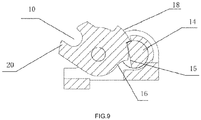
FIG. 9 is a schematic semi-cross-sectional view ofFIG. 8 ; -
FIG. 10 is a schematic structural diagram according to a second embodiment of the present invention; and -
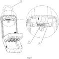
FIG. 11 is a schematic diagram of mounting of a hook structure according to the second embodiment of the present invention. - In the
figures: 1 . Housing; 2. Cavity; 3. Front panel; 4. Locking mechanism; 5. Lock tongue; 6. Mounting assembly; 7. Lock bracket; 8. Rotating shaft; 9. Locking hook spring; 10. Locking hook groove; 11. Locking pin; 12. Battery; 13. Motor; 14. Main shaft; 15. Oblique notch; 16. Locking recess; 17. Unlocking positioning groove; 18. Limiting protrusion; 19. - Return spring; 20. Locking pressing block; 21. Protective cover; 22. Fixing screw hole; 23. LED lighting lamp; 24. Key hook; 25. Hook; 26. Hook locking plate; 27. Compression spring.
- The following further describes the present invention with reference to the accompanying drawings and specific embodiments:
First embodiment: referring toFIG. 1 to FIG. 9 , an electronic key storage case comprises ahousing 1, acavity 2 defined in thehousing 1 and configured for storage, afront panel 3 configured for password input and disposed on the front of thehousing 1, and a locking mechanism 4 and a control circuit disposed on an inner side of thefront panel 3. The locking mechanism 4 is an electronic lock, and comprises a driving circuit, alock tongue 5, and a mountingassembly 6 connected with thelock tongue 5. - The driving circuit is configured to receive unlocking information from the control circuit and control an action on the
lock tongue 5. - The mounting
assembly 6 comprises alock bracket 7, arotating shaft 8 located on thelock bracket 7, and alocking hook spring 9 disposed on therotating shaft 8. Thelock tongue 5 is sleeved on therotating shaft 8, an acting end of thelocking hook spring 9 is connected to thelock tongue 5. A lockinghook groove 10 is provided on thelock tongue 5, and the lockinghook groove 10 is matched with a lockingpin 11 on thehousing 1. - The
lock tongue 5 cooperates with thelocking hook spring 9 through the driving circuit to obtain a degree of freedom of forward or reverse rotation with therotating shaft 8 as a central axis, to form two states of the lockinghook groove 10 engaged with or separated from the lockingpin 11. - As shown in
FIG. 7 andFIG. 9 , the driving circuit comprises abattery 12, a control circuit, and amotor 13. The control circuit controls rotation of themotor 13, a cam structure is disposed on amain shaft 14 outputted by themotor 13, therotating shaft 8 in the mountingassembly 6 and themain shaft 14 are disposed in parallel, and an outer edge surface of thelock tongue 5 is connected with the cam structure. In this embodiment, the cam structure is that, anoblique notch 15 is provided on a side of themain shaft 14, and the outer edge surface of thelock tongue 5 is matched with theoblique notch 15. A distance from theoblique notch 15 to a center of a circle is less than a radius, so that a cam effect is formed. Thelock tongue 5 is matched with the outer edge surfaces at different distances to switch from one state to another state. The specific matching manner is as follows: - A locking
recess 16, an unlockingpositioning groove 17, and a limitingprotrusion 18 are sequentially provided on the outer edge surface of thelock tongue 5. The lockingrecess 16 is matched with an outer edge surface of themain shaft 14, the unlockingpositioning groove 17 is matched with theoblique notch 15, and the limitingprotrusion 18 abuts against a junction between theoblique notch 15 and the outer edge surface of themain shaft 14 to limit thelock tongue 5 to an unlocking state, and the acting end of thelocking hook spring 9 is buckled onto the limitingprotrusion 18 to enable thelock tongue 5 to rotate toward a side of themain shaft 14 with therotating shaft 8 as a center. - When the
main shaft 14 rotates forward (rotates clockwise), theoblique notch 15 is turned to thelock tongue 5. Under the acting force of thelocking hook spring 9, thelock tongue 5 rotates toward the side of themain shaft 14 from the lockingrecess 16 to the unlockingpositioning groove 17 until abutting against the limitingprotrusion 18 as shown inFIG. 9 . In this state, the lockinghook groove 10 of thelock tongue 5 is separated from the lockingpin 11. As shown inFIG. 8 , thefront panel 3 of thehousing 1 is automatically opened under the action of gravity. - On the contrary, when the
front panel 3 is closed, themain shaft 14 and thelock tongue 5 need to be returned respectively. Areturn spring 19 is sleeved on themain shaft 14 of themotor 13 to enable themain shaft 14 to rotate reversely (rotate anticlockwise). The lockinghook groove 10 on thelock tongue 5 is formed by two groove sidewalls and an inward concave arc surface. One groove sidewall extends outward to form alocking pressing block 20. The lockingpin 11 acts on thelocking pressing block 20 to make thelock tongue 5 to rotate reversely, thereby extending thelocking hook spring 9, and forming the state of the lockinghook groove 10 engaged with the lockingpin 11. - When the
front panel 3 is shut down, thefront panel 3 is closed. Since the lockingpin 11 pushes thelocking pressing block 20 on thelock tongue 5, thelock tongue 5 is switched from the unlockingpositioning groove 17 to the lockingrecess 16. In this case, themain shaft 14 rotates reversely under the force of thereturn spring 19, theoblique notch 15 rotates downward, and the outer edge surface of themain shaft 14 abuts against the lockingrecess 16 of thelock tongue 5. As shown inFIG. 7 , thelock tongue 5 is locked and cannot be turned back. In this case, the lockinghook groove 10 is engaged with the lockingpin 11. As shown inFIG. 6 , thefront panel 3 of thehousing 1 is locked. - In switching between two states of engagement and separation, the locking
hook spring 9 and thereturn spring 19 are mutual cooperated each other, so that the driving circuit only needs to drive themotor 13 to rotate toward one direction without considering a driving force for returning by using a dry cell battery 12 (direct current), leading to simplified driving, convenience in mounting, and a smaller and more compact structure. - As shown in
FIG. 2 andFIG. 3 , aprotective cover 21 is disposed on an outer side of thefront panel 3, one end of theprotective cover 21 is pivotally connected with a bottom surface of thehousing 1 by a pin shaft, and the other end of theprotective cover 21 is connected with a top surface of thehousing 1 by a buckle in an engaged manner. Dustproof and waterproof protection on thefront panel 3 of thehousing 1 is achieved. Theprotective cover 21 is opened to input an unlocking password. A plurality of fixing screw holes 22 are provided on a back side of thehousing 1, and thehousing 1 is fixedly mounted on a wall beside a door by bolts. - As shown in
FIG. 4 , anLED lighting lamp 23 and akey hook 24 are disposed on an inner wall of thehousing 1. A delay switch of theLED lighting lamp 23 is connected with the control circuit. When the front panel of thehousing 1 is opened, theLED lighting lamp 23 is switched on, and the LED lighting lamp is automatically switched off after a delay of the delay switch. - An emergency socket is further provided on the outer side of the
housing 1. When thebattery 12 is low, an external power supply (for example, an existing mobile power supply) can be plugged in the emergency socket, so that an emergence start is implemented. After a correct password is inputted, thehousing 1 is opened, and the battery is replaced with anew battery 12, to resume normal use. - Second embodiment: referring to
FIG. 10 andFIG. 11 , an electronic key storage case comprises ahousing 1, acavity 2 defined in thehousing 1 and configured for storage, afront panel 3 configured for password input and disposed on the front of thehousing 1, and a locking mechanism 4 and a control circuit disposed on an inner side of thefront panel 3. The locking mechanism 4 is an electronic lock, and comprises a driving circuit, alock tongue 5, and a mountingassembly 6 connected with thelock tongue 5. In this embodiment, the electronic key storage case has similar structure with that of the first embodiment, except that: an alternating current may be chosen as input of the driving circuit, so that positive and negative paths of the motor is controlled by the control circuit to achieve forward and reverse rotation of the main shaft. Therefore, in this embodiment, there is no need to use the return spring to return the main shaft. This solution is not as simple in structure as the first embodiment, and double springs in the first embodiment are preferred. - As shown in
FIG. 10 , a hook structure is disposed at the top of thehousing 1. The hook structure comprises ahook 25 located on an outer side of thehousing 1 and ahook locking plate 26 located on an inner side of thehousing 1. An end portion of thehook 25 passes through a mounting hole at the top of thehousing 1 and is fixed in thehousing 1 by thehook locking plate 26. As shown inFIG. 11 , if thehook locking plate 26 is moved, thehook 25 may come out. Thehook 25 is clamped by acompression spring 27 during locking, to achieve a connection between thehook 25 and thehousing 1. If a mounting manner using the hook structure is adopted, there is no need to open holes on thehousing 1 and a mounting wall, and the mounting is more convenient.
Claims (10)
- An electronic key storage case, comprising a housing (1), a cavity (2) defined in the housing and configured for storage, a front panel (3) configured for password input and disposed on the front of the housing, a locking mechanism (4) and a control circuit disposed on an inner side of the front panel, characterized in that: the locking mechanism is an electronic lock and comprises a driving circuit, a lock tongue (5) and a mounting assembly (6) connected with the lock tongue,the driving circuit comprises a motor (13) outputting a main shaft (14) and the driving circuit is configured to receive unlocking information from the control circuit and control an action on the lock tongue;the mounting assembly comprises a lock bracket (7), a rotating shaft (8) located on the lock bracket, and a locking hook spring (9) disposed on the rotating shaft, the lock tongue is sleeved on the rotating shaft, an acting end of the locking hook spring is connected with the lock tongue, a locking hook groove (10) is provided on the lock tongue, and the locking hook groove is matched with a locking pin (11) on the housing; andthe lock tongue cooperates with the locking hook spring through the driving circuit, to obtain a degree of freedom of forward or reverse rotation with the rotating shaft as a central axis, to form two states of the locking hook groove engaged with or separated from the locking pin, wherein when the main shaft under the action of the motor rotates clockwise, the lock tongue can rotate under the acting force of the locking hook spring so that the locking hook groove of the lock tongue is separated from the locking pin.
- The electronic key storage case according to claim 1, characterized in that the driving circuit comprises a power supply, a control circuit and the motor, the control circuit controls rotation of the motor, a cam structure is disposed on the main shaft outputted by the motor, the rotating shaft of the mounting assembly and the main shaft are disposed in parallel, and an outer edge surface of the lock tongue is connected with the cam structure.
- The electronic key storage case according to claim 2, characterized in that the cam structure is an oblique notch (15) provided on a side of the main shaft, and the outer edge surface of the lock tongue is matched with the oblique notch.
- The electronic key storage case according to claim 3, characterized in that a locking recess (16), an unlocking positioning groove (17), and a limiting protrusion (18) are sequentially provided on the outer edge surface of the lock tongue, the locking recess is matched with an outer edge surface of the main shaft, the unlocking positioning groove is matched with the oblique notch, and the limiting protrusion abuts against a junction between the oblique notch and the outer edge surface of the main shaft to limit the lock tongue to an unlocking state; and the acting end of the locking hook spring is buckled onto the limiting protrusion to enable the lock tongue to rotate toward a side of the main shaft with the rotating shaft as a center.
- The electronic key storage case according to claim 2, characterized in that a return spring (19) is sleeved on the main shaft of the motor, and the motor is driven by the power supply to rotate forward, and is returned by a reverse force of the return spring.
- The electronic key storage case according to claim 1 or 2, characterized in that the locking hook groove on the lock tongue is formed by two groove sidewalls and an inward concave arc surface, one groove sidewall extends outward to form a locking pressing block (20), the locking pin acts on the locking pressing block to make the lock tongue to rotate reversely, so that the locking hook spring is extended and the state of the locking hook groove engaged with the locking pin is formed.
- The electronic key storage case according to claim 1, characterized in that a plurality of fixing screw holes (22) are provided on a back side of the housing, and the housing is fixedly mounted on a wall beside a door by bolts.
- The electronic key storage case according to claim 1, characterized in that a hook structure (25) is disposed at the top of the housing, the hook structure comprises a hook located on an outer side of the housing and a hook locking plate (26) located on an inner side of the housing, and an end portion of the hook passes through a mounting hole at the top of the housing and is fixed in the housing by the hook locking plate.
- The electronic key storage case according to claim 1, characterized in that a protective cover (21) is disposed on an outer side of the front panel, one end of the protective cover is pivotally connected with a bottom surface of the housing by a pin shaft, and the other end of the protective cover is connected with a top surface of the housing by a buckle in an engaged manner.
- The electronic key storage case according to claim 1, characterized in that an LED lighting lamp (23) and a key hook (24) are disposed on an inner wall of the housing, a delay switch of the LED lighting lamp is connected with the control circuit, when the front panel of the housing is opened, the LED lighting lamp is switched on, and the LED lighting lamp is automatically switched off after a delay of the delay switch.
Applications Claiming Priority (2)
| Application Number | Priority Date | Filing Date | Title |
|---|---|---|---|
| CN201810471103.4A CN108425553B (en) | 2018-05-17 | 2018-05-17 | Electronic key storage box |
| PCT/CN2019/083625 WO2019218846A1 (en) | 2018-05-17 | 2019-04-22 | Electronic key storage case |
Publications (3)
| Publication Number | Publication Date |
|---|---|
| EP3782503A1 EP3782503A1 (en) | 2021-02-24 |
| EP3782503A4 EP3782503A4 (en) | 2021-06-09 |
| EP3782503B1 true EP3782503B1 (en) | 2021-12-22 |
Family
ID=63163357
Family Applications (1)
| Application Number | Title | Priority Date | Filing Date |
|---|---|---|---|
| EP19802982.9A Active EP3782503B1 (en) | 2018-05-17 | 2019-04-22 | Electronic key storage case |
Country Status (6)
| Country | Link |
|---|---|
| US (1) | US11773621B2 (en) |
| EP (1) | EP3782503B1 (en) |
| CN (1) | CN108425553B (en) |
| AU (1) | AU2019271771B2 (en) |
| ES (1) | ES2906172T3 (en) |
| WO (1) | WO2019218846A1 (en) |
Cited By (1)
| Publication number | Priority date | Publication date | Assignee | Title |
|---|---|---|---|---|
| USD1102871S1 (en) | 2024-10-21 | 2025-11-25 | Neo Apex Limited | Key storage lock box |
Families Citing this family (18)
| Publication number | Priority date | Publication date | Assignee | Title |
|---|---|---|---|---|
| CN108425553B (en) * | 2018-05-17 | 2023-08-01 | 苏州锦璘金属有限公司 | Electronic key storage box |
| CN109079983B (en) * | 2018-09-27 | 2020-07-24 | 安徽中沃建筑工程有限公司 | An environmental protection dust cover used in construction projects |
| CN109318365B (en) * | 2018-09-27 | 2020-12-11 | 滨州农一电子商务有限公司 | An environmental protection universal dust cover used in construction projects |
| CN110537766A (en) * | 2019-09-26 | 2019-12-06 | 深圳市龙兄弟数码锁有限公司 | Drawer type electronic key box |
| CN111058695B (en) * | 2020-01-19 | 2025-06-06 | 珠海理想科技有限公司 | Parallel electric locking mechanism |
| CN111827800B (en) * | 2020-06-30 | 2025-01-10 | 深圳市飞洛克科技有限公司 | Key Box |
| USD1008779S1 (en) * | 2021-02-01 | 2023-12-26 | Changjiang Wang | Cipher box |
| CN113319801B (en) * | 2021-05-28 | 2022-12-27 | 日照市睿航地理信息工程有限公司 | Can protect surveying and mapping instrument case that surveying and mapping equipment is not fragile and wets |
| RU210081U1 (en) * | 2021-06-16 | 2022-03-28 | Общество с ограниченной ответственностью "Идеалкей" | UNIVERSAL KEY |
| CN114013813B (en) * | 2021-12-02 | 2023-08-18 | 浙江原数科技有限公司 | Censoring equipment and censoring system |
| CN114607213A (en) * | 2022-04-15 | 2022-06-10 | 王浩然 | A password lock box |
| CN114652058B (en) * | 2022-05-11 | 2023-10-10 | 台州市沃成铜业有限公司 | A fingerprint recognition keychain |
| CN115788168A (en) * | 2022-12-06 | 2023-03-14 | 广东欧派克家居智能科技有限公司 | Lock set |
| US20240247787A1 (en) * | 2023-01-23 | 2024-07-25 | Musco Corporation | Extended knuckle, snout, and aiming device for retrofitting a lighting system with led lights |
| CN118008044B (en) * | 2023-06-25 | 2025-04-22 | 江门异星人摩托车配件有限公司 | Intelligent electronic lock with removable battery |
| GB202309890D0 (en) * | 2023-06-29 | 2023-08-16 | Procare Shower & Bathroom Centre Ltd | Secure storage apparatus |
| CN116980508B (en) * | 2023-06-29 | 2024-04-05 | 荣耀终端有限公司 | Locking mechanism and foldable electronic device |
| TWI853715B (en) * | 2023-09-21 | 2024-08-21 | 彰彬工業股份有限公司 | Lock |
Family Cites Families (30)
| Publication number | Priority date | Publication date | Assignee | Title |
|---|---|---|---|---|
| US3867823A (en) | 1973-10-09 | 1975-02-25 | Napoleon Waltower | Key case |
| US4659121A (en) * | 1984-03-08 | 1987-04-21 | Mcgee Michael H | Garage door lock system |
| US5280518A (en) * | 1985-10-16 | 1994-01-18 | Supra Products, Inc. | Electronic security system |
| US4916443A (en) * | 1985-10-16 | 1990-04-10 | Supra Products, Inc. | Method and apparatus for compiling data relating to operation of an electronic lock system |
| US4838052A (en) * | 1987-07-23 | 1989-06-13 | Segwill Corp. | Lock system |
| DE19614123A1 (en) * | 1996-04-11 | 1997-10-16 | Bosch Gmbh Robert | Car door lock |
| US5791172A (en) * | 1996-09-20 | 1998-08-11 | Multacc Corporation | Electronically controlled security container for retaining door key |
| US5881584A (en) * | 1996-11-13 | 1999-03-16 | Brunoski; Thomas T. | Portable shockproof locking mechanism |
| US6361089B1 (en) * | 2000-06-16 | 2002-03-26 | Atlantes Services, Inc. | Adaptable low-power electronic locking mechanism |
| US6557911B2 (en) * | 2001-01-23 | 2003-05-06 | Kiekert Ag | Power-open motor-vehicle door latch |
| US7061367B2 (en) * | 2002-04-30 | 2006-06-13 | General Electric Company | Managing access to physical assets |
| DE10222136A1 (en) * | 2002-05-17 | 2003-12-04 | Kiekert Ag | Motor vehicle door lock |
| GB0406376D0 (en) * | 2004-03-22 | 2004-04-21 | Maple Alan J | Lock mechanism |
| US20070159297A1 (en) | 2005-12-27 | 2007-07-12 | Paulk Howard L | Secure Key Lock Box System |
| CN201261981Y (en) * | 2008-07-24 | 2009-06-24 | 王劲松 | Coded lock with key box |
| EP2372068A3 (en) * | 2010-04-02 | 2012-08-08 | Master Lock Company LLC | Lockable enclosure with loading cartridge |
| US8950223B1 (en) * | 2011-01-14 | 2015-02-10 | Sean T. Joyce | Personal lock-out box with timer |
| US9777512B2 (en) * | 2011-04-14 | 2017-10-03 | Janus International Group, Llc | Locking apparatus for a rollup door or other movable object |
| US9053629B2 (en) * | 2013-03-14 | 2015-06-09 | Sentrilock, Llc | Contextual data delivery to mobile users responsive to access of an electronic lockbox |
| CN104234528A (en) * | 2013-06-20 | 2014-12-24 | 昆山通用锁具有限公司 | Coded lock for key boxes |
| CN203594282U (en) * | 2013-11-29 | 2014-05-14 | 上海埃海迪机械有限公司 | Movable type storage coded lock box |
| US9889979B2 (en) * | 2014-12-30 | 2018-02-13 | Safemark Systems, Lp | System and method for controlling lock-box with backlit front panel |
| US9540845B1 (en) * | 2015-07-14 | 2017-01-10 | Yao-Kun Yang | Lock unit with a room therein |
| CN106174995A (en) * | 2016-09-13 | 2016-12-07 | 深圳市咕噜科技有限公司 | Intelligent key box |
| CN206928790U (en) * | 2017-06-23 | 2018-01-26 | 湖南金码智能设备制造有限公司 | A kind of cell cabinet door lock that auto-lock function is realized by motor positive and inverse |
| CN107956328B (en) * | 2017-12-14 | 2023-02-24 | 安徽华菱西厨装备股份有限公司 | Lock catch mechanism, lock body and application of lock catch mechanism and lock body in kitchen equipment |
| CN108425553B (en) * | 2018-05-17 | 2023-08-01 | 苏州锦璘金属有限公司 | Electronic key storage box |
| CN208473482U (en) * | 2018-05-17 | 2019-02-05 | 苏州锦璘金属有限公司 | A kind of electronic lock structure |
| CN208396461U (en) * | 2018-05-17 | 2019-01-18 | 苏州锦璘金属有限公司 | Electron key takes care of box |
| EP3803811B1 (en) * | 2018-06-02 | 2024-04-10 | Noke, Inc. | Lockout management systems and methods with multi-keyholder electronic locking devices |
-
2018
- 2018-05-17 CN CN201810471103.4A patent/CN108425553B/en active Active
-
2019
- 2019-04-22 WO PCT/CN2019/083625 patent/WO2019218846A1/en not_active Ceased
- 2019-04-22 ES ES19802982T patent/ES2906172T3/en active Active
- 2019-04-22 AU AU2019271771A patent/AU2019271771B2/en active Active
- 2019-04-22 US US17/055,992 patent/US11773621B2/en active Active
- 2019-04-22 EP EP19802982.9A patent/EP3782503B1/en active Active
Cited By (1)
| Publication number | Priority date | Publication date | Assignee | Title |
|---|---|---|---|---|
| USD1102871S1 (en) | 2024-10-21 | 2025-11-25 | Neo Apex Limited | Key storage lock box |
Also Published As
| Publication number | Publication date |
|---|---|
| US11773621B2 (en) | 2023-10-03 |
| AU2019271771A1 (en) | 2020-11-26 |
| US20210214969A1 (en) | 2021-07-15 |
| CN108425553B (en) | 2023-08-01 |
| ES2906172T3 (en) | 2022-04-13 |
| EP3782503A4 (en) | 2021-06-09 |
| AU2019271771B2 (en) | 2024-02-22 |
| WO2019218846A1 (en) | 2019-11-21 |
| CN108425553A (en) | 2018-08-21 |
| EP3782503A1 (en) | 2021-02-24 |
Similar Documents
| Publication | Publication Date | Title |
|---|---|---|
| AU2019271771B2 (en) | Electronic key storage case | |
| US12020522B2 (en) | Electronic cam lock for cabinet doors, drawers and other applications | |
| US7948359B2 (en) | Electronic security device | |
| EP1032742B1 (en) | Electronic padlock and method for operating its motor | |
| US5794466A (en) | Key safe for housing a key | |
| EP2313582B1 (en) | Electronic lock for cabinet doors, drawers and other applications | |
| US5886644A (en) | Programmable digital electronic lock | |
| US8683833B2 (en) | Electronic access control handle set for a door lock | |
| US7845201B2 (en) | Electronic access control device | |
| US5758522A (en) | Access control system for security enclosure | |
| KR200227883Y1 (en) | The locking & unlocking apparatus for security file cabinet door. | |
| JPH06229155A (en) | Security lock mechanism | |
| EP1842990B1 (en) | Electronic access control device | |
| US20220145670A1 (en) | Lock assembly for a bicycle | |
| WO2001086097A2 (en) | Wireless electromechanical lock | |
| US6341513B1 (en) | Two-in-one combination safe lock | |
| JP2005256367A (en) | Lock handle device for door with fingerprint authentication device | |
| KR101700387B1 (en) | An Electric Type of Locking Device Having A Structure of Sliding Open and Shut | |
| JPWO2008069210A1 (en) | Lockbox with key | |
| US20050179556A1 (en) | Alarm device for pickproofing a lock member | |
| KR100446255B1 (en) | Digital door locker | |
| CN213269358U (en) | Intelligent lock | |
| WO2015160847A1 (en) | Electronic cam lock for cabinet doors, drawers and other applications | |
| KR20020027284A (en) | The locking & unlocking apparatus for security file cabinet door. |
Legal Events
| Date | Code | Title | Description |
|---|---|---|---|
| STAA | Information on the status of an ep patent application or granted ep patent |
Free format text: STATUS: THE INTERNATIONAL PUBLICATION HAS BEEN MADE |
|
| PUAI | Public reference made under article 153(3) epc to a published international application that has entered the european phase |
Free format text: ORIGINAL CODE: 0009012 |
|
| STAA | Information on the status of an ep patent application or granted ep patent |
Free format text: STATUS: REQUEST FOR EXAMINATION WAS MADE |
|
| 17P | Request for examination filed |
Effective date: 20201118 |
|
| AK | Designated contracting states |
Kind code of ref document: A1 Designated state(s): AL AT BE BG CH CY CZ DE DK EE ES FI FR GB GR HR HU IE IS IT LI LT LU LV MC MK MT NL NO PL PT RO RS SE SI SK SM TR |
|
| AX | Request for extension of the european patent |
Extension state: BA ME |
|
| A4 | Supplementary search report drawn up and despatched |
Effective date: 20210511 |
|
| RIC1 | Information provided on ipc code assigned before grant |
Ipc: A45C 11/32 20060101AFI20210504BHEP Ipc: E05B 47/00 20060101ALI20210504BHEP Ipc: E05B 47/06 20060101ALI20210504BHEP Ipc: E05C 3/24 20060101ALI20210504BHEP Ipc: E05B 19/00 20060101ALI20210504BHEP |
|
| DAV | Request for validation of the european patent (deleted) | ||
| DAX | Request for extension of the european patent (deleted) | ||
| RIC1 | Information provided on ipc code assigned before grant |
Ipc: E05B 19/00 20060101ALI20210824BHEP Ipc: E05C 3/24 20060101ALI20210824BHEP Ipc: E05B 47/06 20060101ALI20210824BHEP Ipc: E05B 47/00 20060101ALI20210824BHEP Ipc: A45C 11/32 20060101AFI20210824BHEP |
|
| GRAP | Despatch of communication of intention to grant a patent |
Free format text: ORIGINAL CODE: EPIDOSNIGR1 |
|
| STAA | Information on the status of an ep patent application or granted ep patent |
Free format text: STATUS: GRANT OF PATENT IS INTENDED |
|
| INTG | Intention to grant announced |
Effective date: 20211007 |
|
| GRAS | Grant fee paid |
Free format text: ORIGINAL CODE: EPIDOSNIGR3 |
|
| GRAA | (expected) grant |
Free format text: ORIGINAL CODE: 0009210 |
|
| STAA | Information on the status of an ep patent application or granted ep patent |
Free format text: STATUS: THE PATENT HAS BEEN GRANTED |
|
| AK | Designated contracting states |
Kind code of ref document: B1 Designated state(s): AL AT BE BG CH CY CZ DE DK EE ES FI FR GB GR HR HU IE IS IT LI LT LU LV MC MK MT NL NO PL PT RO RS SE SI SK SM TR |
|
| REG | Reference to a national code |
Ref country code: GB Ref legal event code: FG4D |
|
| REG | Reference to a national code |
Ref country code: CH Ref legal event code: EP |
|
| REG | Reference to a national code |
Ref country code: DE Ref legal event code: R096 Ref document number: 602019010326 Country of ref document: DE |
|
| REG | Reference to a national code |
Ref country code: AT Ref legal event code: REF Ref document number: 1456506 Country of ref document: AT Kind code of ref document: T Effective date: 20220115 |
|
| REG | Reference to a national code |
Ref country code: IE Ref legal event code: FG4D |
|
| REG | Reference to a national code |
Ref country code: LT Ref legal event code: MG9D |
|
| REG | Reference to a national code |
Ref country code: ES Ref legal event code: FG2A Ref document number: 2906172 Country of ref document: ES Kind code of ref document: T3 Effective date: 20220413 |
|
| PG25 | Lapsed in a contracting state [announced via postgrant information from national office to epo] |
Ref country code: RS Free format text: LAPSE BECAUSE OF FAILURE TO SUBMIT A TRANSLATION OF THE DESCRIPTION OR TO PAY THE FEE WITHIN THE PRESCRIBED TIME-LIMIT Effective date: 20211222 Ref country code: LT Free format text: LAPSE BECAUSE OF FAILURE TO SUBMIT A TRANSLATION OF THE DESCRIPTION OR TO PAY THE FEE WITHIN THE PRESCRIBED TIME-LIMIT Effective date: 20211222 Ref country code: FI Free format text: LAPSE BECAUSE OF FAILURE TO SUBMIT A TRANSLATION OF THE DESCRIPTION OR TO PAY THE FEE WITHIN THE PRESCRIBED TIME-LIMIT Effective date: 20211222 Ref country code: BG Free format text: LAPSE BECAUSE OF FAILURE TO SUBMIT A TRANSLATION OF THE DESCRIPTION OR TO PAY THE FEE WITHIN THE PRESCRIBED TIME-LIMIT Effective date: 20220322 |
|
| REG | Reference to a national code |
Ref country code: NL Ref legal event code: MP Effective date: 20211222 |
|
| REG | Reference to a national code |
Ref country code: AT Ref legal event code: MK05 Ref document number: 1456506 Country of ref document: AT Kind code of ref document: T Effective date: 20211222 |
|
| PG25 | Lapsed in a contracting state [announced via postgrant information from national office to epo] |
Ref country code: SE Free format text: LAPSE BECAUSE OF FAILURE TO SUBMIT A TRANSLATION OF THE DESCRIPTION OR TO PAY THE FEE WITHIN THE PRESCRIBED TIME-LIMIT Effective date: 20211222 Ref country code: NO Free format text: LAPSE BECAUSE OF FAILURE TO SUBMIT A TRANSLATION OF THE DESCRIPTION OR TO PAY THE FEE WITHIN THE PRESCRIBED TIME-LIMIT Effective date: 20220322 Ref country code: LV Free format text: LAPSE BECAUSE OF FAILURE TO SUBMIT A TRANSLATION OF THE DESCRIPTION OR TO PAY THE FEE WITHIN THE PRESCRIBED TIME-LIMIT Effective date: 20211222 Ref country code: HR Free format text: LAPSE BECAUSE OF FAILURE TO SUBMIT A TRANSLATION OF THE DESCRIPTION OR TO PAY THE FEE WITHIN THE PRESCRIBED TIME-LIMIT Effective date: 20211222 Ref country code: GR Free format text: LAPSE BECAUSE OF FAILURE TO SUBMIT A TRANSLATION OF THE DESCRIPTION OR TO PAY THE FEE WITHIN THE PRESCRIBED TIME-LIMIT Effective date: 20220323 |
|
| PG25 | Lapsed in a contracting state [announced via postgrant information from national office to epo] |
Ref country code: NL Free format text: LAPSE BECAUSE OF FAILURE TO SUBMIT A TRANSLATION OF THE DESCRIPTION OR TO PAY THE FEE WITHIN THE PRESCRIBED TIME-LIMIT Effective date: 20211222 |
|
| PG25 | Lapsed in a contracting state [announced via postgrant information from national office to epo] |
Ref country code: SM Free format text: LAPSE BECAUSE OF FAILURE TO SUBMIT A TRANSLATION OF THE DESCRIPTION OR TO PAY THE FEE WITHIN THE PRESCRIBED TIME-LIMIT Effective date: 20211222 Ref country code: SK Free format text: LAPSE BECAUSE OF FAILURE TO SUBMIT A TRANSLATION OF THE DESCRIPTION OR TO PAY THE FEE WITHIN THE PRESCRIBED TIME-LIMIT Effective date: 20211222 Ref country code: RO Free format text: LAPSE BECAUSE OF FAILURE TO SUBMIT A TRANSLATION OF THE DESCRIPTION OR TO PAY THE FEE WITHIN THE PRESCRIBED TIME-LIMIT Effective date: 20211222 Ref country code: PT Free format text: LAPSE BECAUSE OF FAILURE TO SUBMIT A TRANSLATION OF THE DESCRIPTION OR TO PAY THE FEE WITHIN THE PRESCRIBED TIME-LIMIT Effective date: 20220422 Ref country code: EE Free format text: LAPSE BECAUSE OF FAILURE TO SUBMIT A TRANSLATION OF THE DESCRIPTION OR TO PAY THE FEE WITHIN THE PRESCRIBED TIME-LIMIT Effective date: 20211222 Ref country code: CZ Free format text: LAPSE BECAUSE OF FAILURE TO SUBMIT A TRANSLATION OF THE DESCRIPTION OR TO PAY THE FEE WITHIN THE PRESCRIBED TIME-LIMIT Effective date: 20211222 |
|
| PG25 | Lapsed in a contracting state [announced via postgrant information from national office to epo] |
Ref country code: PL Free format text: LAPSE BECAUSE OF FAILURE TO SUBMIT A TRANSLATION OF THE DESCRIPTION OR TO PAY THE FEE WITHIN THE PRESCRIBED TIME-LIMIT Effective date: 20211222 Ref country code: AT Free format text: LAPSE BECAUSE OF FAILURE TO SUBMIT A TRANSLATION OF THE DESCRIPTION OR TO PAY THE FEE WITHIN THE PRESCRIBED TIME-LIMIT Effective date: 20211222 |
|
| REG | Reference to a national code |
Ref country code: DE Ref legal event code: R097 Ref document number: 602019010326 Country of ref document: DE |
|
| PG25 | Lapsed in a contracting state [announced via postgrant information from national office to epo] |
Ref country code: IS Free format text: LAPSE BECAUSE OF FAILURE TO SUBMIT A TRANSLATION OF THE DESCRIPTION OR TO PAY THE FEE WITHIN THE PRESCRIBED TIME-LIMIT Effective date: 20220422 |
|
| PLBE | No opposition filed within time limit |
Free format text: ORIGINAL CODE: 0009261 |
|
| STAA | Information on the status of an ep patent application or granted ep patent |
Free format text: STATUS: NO OPPOSITION FILED WITHIN TIME LIMIT |
|
| PG25 | Lapsed in a contracting state [announced via postgrant information from national office to epo] |
Ref country code: DK Free format text: LAPSE BECAUSE OF FAILURE TO SUBMIT A TRANSLATION OF THE DESCRIPTION OR TO PAY THE FEE WITHIN THE PRESCRIBED TIME-LIMIT Effective date: 20211222 Ref country code: AL Free format text: LAPSE BECAUSE OF FAILURE TO SUBMIT A TRANSLATION OF THE DESCRIPTION OR TO PAY THE FEE WITHIN THE PRESCRIBED TIME-LIMIT Effective date: 20211222 |
|
| 26N | No opposition filed |
Effective date: 20220923 |
|
| REG | Reference to a national code |
Ref country code: CH Ref legal event code: PL |
|
| REG | Reference to a national code |
Ref country code: BE Ref legal event code: MM Effective date: 20220430 |
|
| PG25 | Lapsed in a contracting state [announced via postgrant information from national office to epo] |
Ref country code: MC Free format text: LAPSE BECAUSE OF FAILURE TO SUBMIT A TRANSLATION OF THE DESCRIPTION OR TO PAY THE FEE WITHIN THE PRESCRIBED TIME-LIMIT Effective date: 20211222 Ref country code: LU Free format text: LAPSE BECAUSE OF NON-PAYMENT OF DUE FEES Effective date: 20220422 Ref country code: LI Free format text: LAPSE BECAUSE OF NON-PAYMENT OF DUE FEES Effective date: 20220430 Ref country code: CH Free format text: LAPSE BECAUSE OF NON-PAYMENT OF DUE FEES Effective date: 20220430 |
|
| PG25 | Lapsed in a contracting state [announced via postgrant information from national office to epo] |
Ref country code: SI Free format text: LAPSE BECAUSE OF FAILURE TO SUBMIT A TRANSLATION OF THE DESCRIPTION OR TO PAY THE FEE WITHIN THE PRESCRIBED TIME-LIMIT Effective date: 20211222 Ref country code: BE Free format text: LAPSE BECAUSE OF NON-PAYMENT OF DUE FEES Effective date: 20220430 |
|
| PG25 | Lapsed in a contracting state [announced via postgrant information from national office to epo] |
Ref country code: IE Free format text: LAPSE BECAUSE OF NON-PAYMENT OF DUE FEES Effective date: 20220422 |
|
| PG25 | Lapsed in a contracting state [announced via postgrant information from national office to epo] |
Ref country code: MK Free format text: LAPSE BECAUSE OF FAILURE TO SUBMIT A TRANSLATION OF THE DESCRIPTION OR TO PAY THE FEE WITHIN THE PRESCRIBED TIME-LIMIT Effective date: 20211222 Ref country code: CY Free format text: LAPSE BECAUSE OF FAILURE TO SUBMIT A TRANSLATION OF THE DESCRIPTION OR TO PAY THE FEE WITHIN THE PRESCRIBED TIME-LIMIT Effective date: 20211222 |
|
| PG25 | Lapsed in a contracting state [announced via postgrant information from national office to epo] |
Ref country code: HU Free format text: LAPSE BECAUSE OF FAILURE TO SUBMIT A TRANSLATION OF THE DESCRIPTION OR TO PAY THE FEE WITHIN THE PRESCRIBED TIME-LIMIT; INVALID AB INITIO Effective date: 20190422 |
|
| PG25 | Lapsed in a contracting state [announced via postgrant information from national office to epo] |
Ref country code: MT Free format text: LAPSE BECAUSE OF FAILURE TO SUBMIT A TRANSLATION OF THE DESCRIPTION OR TO PAY THE FEE WITHIN THE PRESCRIBED TIME-LIMIT Effective date: 20211222 |
|
| PGFP | Annual fee paid to national office [announced via postgrant information from national office to epo] |
Ref country code: DE Payment date: 20250213 Year of fee payment: 7 |
|
| PGFP | Annual fee paid to national office [announced via postgrant information from national office to epo] |
Ref country code: ES Payment date: 20250519 Year of fee payment: 7 |
|
| PGFP | Annual fee paid to national office [announced via postgrant information from national office to epo] |
Ref country code: IT Payment date: 20250430 Year of fee payment: 7 |
|
| PGFP | Annual fee paid to national office [announced via postgrant information from national office to epo] |
Ref country code: FR Payment date: 20250422 Year of fee payment: 7 |
|
| PG25 | Lapsed in a contracting state [announced via postgrant information from national office to epo] |
Ref country code: TR Free format text: LAPSE BECAUSE OF FAILURE TO SUBMIT A TRANSLATION OF THE DESCRIPTION OR TO PAY THE FEE WITHIN THE PRESCRIBED TIME-LIMIT Effective date: 20211222 |
|
| PGFP | Annual fee paid to national office [announced via postgrant information from national office to epo] |
Ref country code: GB Payment date: 20260324 Year of fee payment: 8 |