EP3781479B1 - Personal flight apparatus with vertical take-off and landing - Google Patents
Personal flight apparatus with vertical take-off and landing Download PDFInfo
- Publication number
- EP3781479B1 EP3781479B1 EP19733892.4A EP19733892A EP3781479B1 EP 3781479 B1 EP3781479 B1 EP 3781479B1 EP 19733892 A EP19733892 A EP 19733892A EP 3781479 B1 EP3781479 B1 EP 3781479B1
- Authority
- EP
- European Patent Office
- Prior art keywords
- wings
- flight
- cockpit
- landing
- duct
- Prior art date
- Legal status (The legal status is an assumption and is not a legal conclusion. Google has not performed a legal analysis and makes no representation as to the accuracy of the status listed.)
- Active
Links
Images


Classifications
-
- B—PERFORMING OPERATIONS; TRANSPORTING
- B64—AIRCRAFT; AVIATION; COSMONAUTICS
- B64C—AEROPLANES; HELICOPTERS
- B64C9/00—Adjustable control surfaces or members, e.g. rudders
- B64C9/14—Adjustable control surfaces or members, e.g. rudders forming slots
- B64C9/146—Adjustable control surfaces or members, e.g. rudders forming slots at an other wing location than the rear or the front
-
- B—PERFORMING OPERATIONS; TRANSPORTING
- B64—AIRCRAFT; AVIATION; COSMONAUTICS
- B64C—AEROPLANES; HELICOPTERS
- B64C11/00—Propellers, e.g. of ducted type; Features common to propellers and rotors for rotorcraft
- B64C11/02—Hub construction
- B64C11/04—Blade mountings
- B64C11/08—Blade mountings for non-adjustable blades
- B64C11/10—Blade mountings for non-adjustable blades rigid
-
- B—PERFORMING OPERATIONS; TRANSPORTING
- B60—VEHICLES IN GENERAL
- B60L—PROPULSION OF ELECTRICALLY-PROPELLED VEHICLES; SUPPLYING ELECTRIC POWER FOR AUXILIARY EQUIPMENT OF ELECTRICALLY-PROPELLED VEHICLES; ELECTRODYNAMIC BRAKE SYSTEMS FOR VEHICLES IN GENERAL; MAGNETIC SUSPENSION OR LEVITATION FOR VEHICLES; MONITORING OPERATING VARIABLES OF ELECTRICALLY-PROPELLED VEHICLES; ELECTRIC SAFETY DEVICES FOR ELECTRICALLY-PROPELLED VEHICLES
- B60L50/00—Electric propulsion with power supplied within the vehicle
- B60L50/50—Electric propulsion with power supplied within the vehicle using propulsion power supplied by batteries or fuel cells
- B60L50/60—Electric propulsion with power supplied within the vehicle using propulsion power supplied by batteries or fuel cells using power supplied by batteries
- B60L50/66—Arrangements of batteries
-
- B—PERFORMING OPERATIONS; TRANSPORTING
- B64—AIRCRAFT; AVIATION; COSMONAUTICS
- B64C—AEROPLANES; HELICOPTERS
- B64C21/00—Influencing air flow over aircraft surfaces by affecting boundary layer flow
- B64C21/02—Influencing air flow over aircraft surfaces by affecting boundary layer flow by use of slot, ducts, porous areas or the like
- B64C21/04—Influencing air flow over aircraft surfaces by affecting boundary layer flow by use of slot, ducts, porous areas or the like for blowing
-
- B—PERFORMING OPERATIONS; TRANSPORTING
- B64—AIRCRAFT; AVIATION; COSMONAUTICS
- B64C—AEROPLANES; HELICOPTERS
- B64C25/00—Alighting gear
- B64C25/02—Undercarriages
- B64C25/04—Arrangement or disposition on aircraft
-
- B—PERFORMING OPERATIONS; TRANSPORTING
- B64—AIRCRAFT; AVIATION; COSMONAUTICS
- B64C—AEROPLANES; HELICOPTERS
- B64C29/00—Aircraft capable of landing or taking-off vertically, e.g. vertical take-off and landing [VTOL] aircraft
- B64C29/0008—Aircraft capable of landing or taking-off vertically, e.g. vertical take-off and landing [VTOL] aircraft having its flight directional axis horizontal when grounded
- B64C29/0016—Aircraft capable of landing or taking-off vertically, e.g. vertical take-off and landing [VTOL] aircraft having its flight directional axis horizontal when grounded the lift during taking-off being created by free or ducted propellers or by blowers
- B64C29/0033—Aircraft capable of landing or taking-off vertically, e.g. vertical take-off and landing [VTOL] aircraft having its flight directional axis horizontal when grounded the lift during taking-off being created by free or ducted propellers or by blowers the propellers being tiltable relative to the fuselage
-
- B—PERFORMING OPERATIONS; TRANSPORTING
- B64—AIRCRAFT; AVIATION; COSMONAUTICS
- B64C—AEROPLANES; HELICOPTERS
- B64C29/00—Aircraft capable of landing or taking-off vertically, e.g. vertical take-off and landing [VTOL] aircraft
- B64C29/02—Aircraft capable of landing or taking-off vertically, e.g. vertical take-off and landing [VTOL] aircraft having its flight directional axis vertical when grounded
-
- B—PERFORMING OPERATIONS; TRANSPORTING
- B64—AIRCRAFT; AVIATION; COSMONAUTICS
- B64C—AEROPLANES; HELICOPTERS
- B64C3/00—Wings
- B64C3/10—Shape of wings
- B64C3/14—Aerofoil profile
- B64C3/141—Circulation Control Airfoils
-
- B—PERFORMING OPERATIONS; TRANSPORTING
- B64—AIRCRAFT; AVIATION; COSMONAUTICS
- B64C—AEROPLANES; HELICOPTERS
- B64C39/00—Aircraft not otherwise provided for
- B64C39/003—Aircraft not otherwise provided for with wings, paddle wheels, bladed wheels, moving or rotating in relation to the fuselage
- B64C39/005—Aircraft not otherwise provided for with wings, paddle wheels, bladed wheels, moving or rotating in relation to the fuselage about a horizontal transversal axis
-
- B—PERFORMING OPERATIONS; TRANSPORTING
- B64—AIRCRAFT; AVIATION; COSMONAUTICS
- B64C—AEROPLANES; HELICOPTERS
- B64C39/00—Aircraft not otherwise provided for
- B64C39/08—Aircraft not otherwise provided for having multiple wings
-
- B—PERFORMING OPERATIONS; TRANSPORTING
- B64—AIRCRAFT; AVIATION; COSMONAUTICS
- B64D—EQUIPMENT FOR FITTING IN OR TO AIRCRAFT; FLIGHT SUITS; PARACHUTES; ARRANGEMENT OR MOUNTING OF POWER PLANTS OR PROPULSION TRANSMISSIONS IN AIRCRAFT
- B64D27/00—Arrangement or mounting of power plants in aircraft; Aircraft characterised by the type or position of power plants
- B64D27/02—Aircraft characterised by the type or position of power plants
- B64D27/16—Aircraft characterised by the type or position of power plants of jet type
- B64D27/18—Aircraft characterised by the type or position of power plants of jet type within, or attached to, wings
-
- B—PERFORMING OPERATIONS; TRANSPORTING
- B64—AIRCRAFT; AVIATION; COSMONAUTICS
- B64D—EQUIPMENT FOR FITTING IN OR TO AIRCRAFT; FLIGHT SUITS; PARACHUTES; ARRANGEMENT OR MOUNTING OF POWER PLANTS OR PROPULSION TRANSMISSIONS IN AIRCRAFT
- B64D27/00—Arrangement or mounting of power plants in aircraft; Aircraft characterised by the type or position of power plants
- B64D27/02—Aircraft characterised by the type or position of power plants
- B64D27/30—Aircraft characterised by electric power plants
- B64D27/34—All-electric aircraft
-
- B—PERFORMING OPERATIONS; TRANSPORTING
- B64—AIRCRAFT; AVIATION; COSMONAUTICS
- B64D—EQUIPMENT FOR FITTING IN OR TO AIRCRAFT; FLIGHT SUITS; PARACHUTES; ARRANGEMENT OR MOUNTING OF POWER PLANTS OR PROPULSION TRANSMISSIONS IN AIRCRAFT
- B64D27/00—Arrangement or mounting of power plants in aircraft; Aircraft characterised by the type or position of power plants
- B64D27/02—Aircraft characterised by the type or position of power plants
- B64D27/30—Aircraft characterised by electric power plants
- B64D27/35—Arrangements for on-board electric energy production, distribution, recovery or storage
- B64D27/357—Arrangements for on-board electric energy production, distribution, recovery or storage using batteries
-
- B—PERFORMING OPERATIONS; TRANSPORTING
- B60—VEHICLES IN GENERAL
- B60L—PROPULSION OF ELECTRICALLY-PROPELLED VEHICLES; SUPPLYING ELECTRIC POWER FOR AUXILIARY EQUIPMENT OF ELECTRICALLY-PROPELLED VEHICLES; ELECTRODYNAMIC BRAKE SYSTEMS FOR VEHICLES IN GENERAL; MAGNETIC SUSPENSION OR LEVITATION FOR VEHICLES; MONITORING OPERATING VARIABLES OF ELECTRICALLY-PROPELLED VEHICLES; ELECTRIC SAFETY DEVICES FOR ELECTRICALLY-PROPELLED VEHICLES
- B60L2200/00—Type of vehicles
- B60L2200/10—Air crafts
-
- B—PERFORMING OPERATIONS; TRANSPORTING
- B64—AIRCRAFT; AVIATION; COSMONAUTICS
- B64C—AEROPLANES; HELICOPTERS
- B64C11/00—Propellers, e.g. of ducted type; Features common to propellers and rotors for rotorcraft
- B64C11/001—Shrouded propellers
-
- Y—GENERAL TAGGING OF NEW TECHNOLOGICAL DEVELOPMENTS; GENERAL TAGGING OF CROSS-SECTIONAL TECHNOLOGIES SPANNING OVER SEVERAL SECTIONS OF THE IPC; TECHNICAL SUBJECTS COVERED BY FORMER USPC CROSS-REFERENCE ART COLLECTIONS [XRACs] AND DIGESTS
- Y02—TECHNOLOGIES OR APPLICATIONS FOR MITIGATION OR ADAPTATION AGAINST CLIMATE CHANGE
- Y02T—CLIMATE CHANGE MITIGATION TECHNOLOGIES RELATED TO TRANSPORTATION
- Y02T10/00—Road transport of goods or passengers
- Y02T10/60—Other road transportation technologies with climate change mitigation effect
- Y02T10/70—Energy storage systems for electromobility, e.g. batteries
-
- Y—GENERAL TAGGING OF NEW TECHNOLOGICAL DEVELOPMENTS; GENERAL TAGGING OF CROSS-SECTIONAL TECHNOLOGIES SPANNING OVER SEVERAL SECTIONS OF THE IPC; TECHNICAL SUBJECTS COVERED BY FORMER USPC CROSS-REFERENCE ART COLLECTIONS [XRACs] AND DIGESTS
- Y02—TECHNOLOGIES OR APPLICATIONS FOR MITIGATION OR ADAPTATION AGAINST CLIMATE CHANGE
- Y02T—CLIMATE CHANGE MITIGATION TECHNOLOGIES RELATED TO TRANSPORTATION
- Y02T50/00—Aeronautics or air transport
- Y02T50/10—Drag reduction
-
- Y—GENERAL TAGGING OF NEW TECHNOLOGICAL DEVELOPMENTS; GENERAL TAGGING OF CROSS-SECTIONAL TECHNOLOGIES SPANNING OVER SEVERAL SECTIONS OF THE IPC; TECHNICAL SUBJECTS COVERED BY FORMER USPC CROSS-REFERENCE ART COLLECTIONS [XRACs] AND DIGESTS
- Y02—TECHNOLOGIES OR APPLICATIONS FOR MITIGATION OR ADAPTATION AGAINST CLIMATE CHANGE
- Y02T—CLIMATE CHANGE MITIGATION TECHNOLOGIES RELATED TO TRANSPORTATION
- Y02T50/00—Aeronautics or air transport
- Y02T50/30—Wing lift efficiency
Definitions
- the disclosure refers to a vertical take-off and landing flight apparatus capable of carrying at least one person and flying, in carrying capacity, in a cruise mode.
- US 3259343 relates to an aircraft frame including a center of gravity and first and second pairs of thrust developing means disposed on opposite sides of said center of gravity, each thrust developing means -of each pair thereof corresponding to a thrust developing means of the other pair thereof, and a plurality of automatic thrust equalizing control means equal in number to said thrust developing means and each operatively connected to a thrust developing means for actuation thereby and to its corresponding thrust developing means of the other pair of thrust developing means for control thereof, each of said control means including means operative, responsive to a reduction of power developed by its actuating thrust developing means below a predetermined minimum, to terminate operation of the thrust developing means controlled thereby.
- US 5071088A relates to a high lift vertical takeoff and landing aircraft has first and second fuselages connected by a central airfoil. Jet engines at the leading edge of the airfoil expel propulsive streams simultaneously over top and bottom surfaces of the foil. Extendable flaps are utilized at a trailing edge of the airfoil with a horizontal control blade being attached to the leading edge of the foil. The control blade is within the jet's propulsive stream to permit proportioning of the stream above and below the airfoil.
- An extendable augmenter wing is attached between the fuselages aft and above the main airfoil to permit airflow in this region to be directed downwardly, accelerating the flow and providing additional lift.
- the main airfoil is positioned so that the fuselage walls extend above and below the foil. Lateral flow of the main engine exhaust is restrained by these walls. Above the wing the walls and airfoil create a venturi to speed airflow and decrease pressure. Below the wing the walls and extended flaps dam exhaust and ambient flow to create a high pressure region. Outboard wings provide secondary lift and reduce main wing loading. A canard is attached between the fuselages to provide pitch control. Both top and bottom canard surfaces are blown by forward mounted engines or exhaust ducts to add lift to the aircraft and to permit upward tilting of the aircraft during takeoff and landing. Tilting the aircraft permits the resultant of the engine thrust and wing lift vectors to be vertical.
- US 2006254255 relates to an aircraft propulsion system which can secure the optimum thrust and thrust vector for flight conditions, as well as the optimum sectional area for the engine, and which is highly compatible with the environment.
- An electrical generator is coupled to a turbofan engine, the electrical generator is driven by output power of the turbofan engine to output electric power, and an electromagnetic driving fan is driven by the electric power.
- liquid hydrogen is introduced to a heat exchanger, collects the energy of exhaust as heat, is then vaporized, and thereafter supplied to a combustor and to a fuel cell.
- the electromagnetic driving fan is changed in its rotational phase by a rotating mechanism portion, is made movable in a width direction of a wing and a wing chord direction by a slide mechanism portion, and can be stored inside or outside the wing by a storage mechanism portion.
- US 2011042509 relates to an aerial vehicle adapted for vertical takeoff and landing using the same set of engines for takeoff and landing as well as for forward flight.
- An aerial vehicle which is adapted to takeoff with the wings in a vertical as opposed to horizontal flight attitude which takes off in this vertical attitude and then transitions to a horizontal flight path.
- An aerial vehicle which controls the attitude of the vehicle during takeoff and landing by alternating the thrust of engines, which are separated in at least two dimensions relative to the horizontal during takeoff, and which may also control regular flight in some aspects by the use of differential thrust of the engines.
- US 2017057648 relates to a propulsion system coupled to a vehicle.
- the system includes an ejector having an outlet structure out of which propulsive fluid flows at a predetermined adjustable velocity.
- a control surface having a leading edge is located directly downstream of the outlet structure such that propulsive fluid from the ejector flows over the control surface.
- EP 3263456 relates to an aircraft (10) having a vertical takeoff and landing fight mode and a forward flight mode.
- the aircraft (10) includes an airframe (12) and a versatile propulsion system attached to the airframe (12).
- the versatile propulsion system includes a plurality of propulsion assemblies (26a-d).
- a flight control system (40) is operable to independently control the propulsion assemblies (26a-d).
- the propulsion assemblies (26a-d) are interchangeably attachable to the airframe (12) such that the aircraft (10) has a liquid fuel flight mode and an electric flight mode. In the liquid fuel flight mode, energy is provided to each of the propulsion assemblies (26a-d) from a liquid fuel. In the electric flight mode, energy is provided to each of the propulsion assemblies (26a-d) from an electric power source.
- US 2018002013 relates to an aircraft including an airframe, a propulsion system attached to the airframe and a flight control system operably associated with the propulsion system.
- a pod assembly is selectively attachable to the flying frame.
- the flying frame has a vertical takeoff and landing mode and a forward flight mode.
- the flying frame has a manned flight mode and an unmanned flight mode.
- the purpose of the present disclosure is to provide a flight apparatus suitable to the above stated requirements.
- the flight apparatus with vertical take-off and landing is characterized in that it is a biplane apparatus constituted by two distinct parts articulated there between, the first distinct part consisting of the cockpit, which is hinged to the second part of the latter, which is formed of the solid support of the wings, the cockpit being attached to the wings assembly by two hinges fixed to the central vertical support pillars of the wings, the cockpit can swing inside of the wing support structure, which in turn is provided with four electric motors with ducted propellers disposed two on the top wing and two on the bottom wing forming a quadcopter assembly, the duct of each propeller being provided on the inlet lip with an annular ejection slit, and the electrical energy required for the operation of the flight apparatus is provided by battery accumulators placed under the pilot's seat, which transmit the power to the engines, the entire operation of the flight apparatus being managed by a flight computer disposed in the central part of the upper wing of the biplane and the take-off takes place with vertically oriented wings and motors, the flight apparatus
- the flight apparatus can be additionally fitted both on wings and on propellers' ducts, with Coanda ejectors.
- the advantages of the flight apparatus with take-off and landing according to the disclosure are as follows: it is capable of taking off and landing vertically, can carry a person (the concept can be extended for the transport of 4-5 persons), ensures a flight of several dozen kilometers, shows low noise, shows good energy efficiency on all flight regimes, has a high degree of safety and low size.
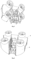
- Figure 1 shows the two distinct and articulated parts of the flight apparatus.
- the first distinct part is made up of the cockpit 1.
- This is made up of a rigid frame, preferably a truss to give it strength and stiffness, and which includes the flight deck which must be large enough to accommodate a comfortable position for a pilot 2.
- the armrests of the pilot seat incorporate the controls panels 13 on the ends. If necessary, the controls can also be ordered in the pedestrian legs or levers.
- the cockpit is open, but it can be partially closed by a front door with a lateral opening or can be completely closed to deviate airflow for pilot's comfort. Under the pilot's seat are the electric batteries 14, as well as the speed controllers of the motors.
- the cockpit 1 has at its bottom a four-wheel assembly 20 that can rotate 360 degrees, so that the flight apparatus can be easily operated on the ground and with the wings in the position for cruise flight.
- a stopper bolt 5 which has the role of limiting the swing of the cockpit within the wings assembly during the cruise flight and it coming into contact with the wings assembly and, from a certain angle of the wings' incidence, to make that the two distinct parts of the apparatus to move jointly together.
- the cockpit 1 which constitutes the second distinct part of the apparatus is attached to the assembly of the wings 6, by means of the bar 4 which enter through common holes both of the cockpit 1 and of the wings assembly 6, thus forming the joints 3.
- the joints 3 will have a controlled friction, allowing a smooth balancing of the cockpit to maintain its verticality to the ground but, without allowing its uncontrolled pivoting.
- the joints 3 are provided on both sides of the pilot 2 with a lever m, which by means of some gears, allows the pilot to manually adjust the wings angle when the pilot wishes or considers that is necessary for a particular maneuver.
- the second distinct part of the flight apparatus is the wings assembly 6 which consists of two wings a and b having a high lift airfoil, forming a biplane assembly, with the upper wing a disposed more advanced than the lower wing b.
- the assembly is stiffened by two central vertical supports 7 which also have the role of supporting the cockpit and by two lateral vertical supports 8 that join the ends of the wings.
- the wings assembly can also be reinforced with spikes (wires).
- the wings have embedded in them the landing gear 15.
- the airfoil must generate high lift at low speeds and at high angles of incidence, and the drag must be low. In this regard, it is preferable to use the profiles described in patent no. EP0772731B1 .
- the flight computer 17 and the survival parachute 18 of the apparatus are disposed in the central area of the upper wing.
- the two wings are provided with four electric ducted propellers 9, two for each wing, and they are arranged symmetrically with respect to the vertical axis of symmetry in a quadcopter specific manner.
- the propellers are fitted with ducts10.
- the lips of the propellers' ducts 10 will be provided with ejection slits 11.
- the wings may be provided alongside them with bi-dimensional Coanda type ejectors 12.
- An overview of a flight apparatus in cruise mode provided with such wing ejectors is illustrated in Fig. 2
- Fig. 3 shows an apparatus not provided with wing ejectors.
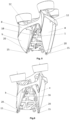
- Fig. 4 shows an overview of the apparatus in a take-off / landing position
- Fig. 5 is a side view showing the landing gear 15 which is located in the wings extensions.
- the four wheels of the landing gear 15 can be rotated 360 degrees and are disposed at the ends of the second A-shaped resistance structures 16 which are integral with the central vertical supports 7.
- the axes of the motors may be slightly inclined forward to the perpendicular to the ground, which can be obtained from the corresponding adjustment of the arms of the resistance structure 16.
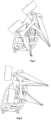
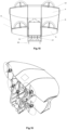
- Fig. 6 is a side view of the apparatus in the take-off / landing position
- Fig. 7 is a side view of the apparatus in flight transition
- Fig. 8 a side view with the apparatus during the cruise flight.
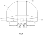
- the wings may have an elliptical shape with the straight ends as described in Fig. 9 , but they may also have the trapezoidal or rectangular shape.
- FIG. 10 illustrates the synergistic operation of the ducted propeller 9 provided with the ejector slit 11 together with the wing ejector 12 and outlines the air flow.
- the electric motor 20 In order for all the propulsion elements to function synergistically, the electric motor 20 must transmits its motion not only to the propeller, but also to an air compressor 22, therefore it is preferred that the electric motor 20 shaft has to cross the motor from one head to the other, so that the motor at one end to engage the propeller's rotor 21, and at the other to engage through a speed multiplier the air compressor 22.
- This air compressor may be axial in order to not have a large section, but also may be centrifugal or even of a Tesla type.
- the air compressor 22 absorbs the air through a circular slit f which surrounds the electric motor 20, and blows and supplies the compressed air via a pipe 23 towards a pressure annular chamber 24 disposed in the rim of the duct 10, and then from the annular chamber 24, the air is ejected under pressure through the ejection slit 11. Due to this ejection, a depression is formed on the upper part of the duct's lip and thus can draw larger masses of air through the interior of the duct 10.
- the air compressor 22 supplies, through the pipe 25, compressed air to the bi-dimensional Coanda ejector 12, which is comprised of a pressure chamber 26 disposed along each wing and which has the ejection slit 30 and the small wing 27 which is disposed all along each wing and which comprises a pressure chamber 28 which has the ejection slit 31.
- the two pressure chambers 26 and 28 have identical dimensions having a tronconic shape and have maximum cross sections in the central areas of the wings and their sections are shrunk to the wings extremities in order to maintain a pressure as uniform as possible uniform within them.
- the two ejection slits 30 and 31 are parallel to one another and the width of their opening is kept constant along them, thus achieving a relatively uniform ejection from one end of the wings to the other.
- the curvature of the upper side wing is identical to the small wing 27 inner profile.
- the airfoil of the small wing 27 airfoil has to be rounded on the leading edge this way generating an air depression and drawing a large mass of air.
- the airflow in the take-off mode is suggested by the arrows represented in Figure 10 .
- the ejection slit 30 as well as the curved profile of the upper side of the wing contribute through the Coanda effect to maintain a uniform boundary layer along the upper side of the wing.
- the small wing 27 can rotate at a certain angle so that the ejector intake area A1 is diminishing and the ejection area A2 increases and this way the pressure on the upper side can be controlled, thus can be mofified the wings' lift force without varying the flight speed of the flight apparatus or the wings' incidence angle.
- the supply of the compressed air through the pipe 23 to the slits 11 may be interrupted by means of the valves 32 and the supply of compressed air to the slit 28 can be interrupted by means of the valve 33 and the compressed air is distributed only to the slit 30.
- the air intake zone decreases, the dynamic thrust of the propeller increases as well as the air pressure in the chamber 26, and the masses of air are accelerated synergistically, and the air ejected under pressure through the slit 30 contributes to achieving a uniform boundary layer on the upper side of the wing.
- the small wing 27 In the constructive variant in which the small wing 27 is mobile, it rotates as the ejection area A2 decreases and consequently, the air accelerates inside the ejector contributing to the thrust.
- the air circulation during the cruise flight is showed by the arrows in Figure 11 .
- the electric motors 20 can be replaced with heat engines. It is preferable that these motors are Wankel rotary, which have a high power / weight ratio and due to their low cross-section and low vibrations, they are suitable for being ducted.
- Wankel rotary which have a high power / weight ratio and due to their low cross-section and low vibrations, they are suitable for being ducted.
- one of the main drawbacks is the high level of noise.
- the duct 10 is doubled outward by another duct 35, which comprises an annular chamber 36 and an ejection slit 37.
- the required compressed air is provided by an extension of the pipe 23 to the annular chamber 36.
- the interior of the duct 35 together with the outside part of the duct 10 forms the profile required for a Coanda ejector through which the air is driven and accelerated inward by means of the ejection slit 37.
- FIG. 13 illustrates a double-flow duct propeller that has both ejection slits for intake 11 and 37 as well and for the evacuation, the slits 38 and 39.
- a large mass of air is driven similar to a propeller of a much larger diameter.
- This concept which implies the existence of a Coanda type ejector that surrounds the main engine, can be extended to the turbojet engines, and in the case that a Coanda ejector surrounds a turbofan it can be achieved even a triple flow jet engine - figure 14 .
- the pipe 23 takes the necessary compressed air from one stage of the compressor 41 and supplies with it the slits 11 and 37.
- the triple flow jet engine may also be provided with evacuation ejection slits.
- the advantages of a triple flow jet engine are as follows: it has a greater efficiency for vertical take-offs or classic take-off phases, a more reduced noise and a reduced thermal footprint.
- Figure 15 shows a rear view of the flight apparatus in cruise flight, where we can see the arrangement of the batteries under the pilot's seat, which leads to a lower center of gravity and better stability of the flight apparatus. Also in the same place may be disposed the speed regulators of the electric motors.
- Figure 16 shows a simpler and less expensive flight apparatus not according to the claimed invention, with simple propellers and no ejectors.
- the flight apparatus is provided with the rescue parachute 18 which is located in the upper wing of the flight apparatus. It is positioned so that when it is open, it will keep the wings of the flight apparatus at an optimal incidence angle for a landing this way. It is preferable that the parachute to be a rectangular wing type, because after the opening, the pilot can access the parachute controls and this way he can maneuver the flight apparatus in a suitable area for landing. Also, as a further safety measure, the pilot can be equipped with the individual parachute.
- the rounded shape of the cockpit's extremities favors the rolling of the flight apparatus which helps to dissipate this way the kinetic energy at the moment of impact with the ground.
- the lateral frames of the cockpit 1 are attached by cables 19 to the central vertical supports 7 of the wings assembly.
- the mode of operation of the flight apparatus is very simple, it flies in quadcopter mode for both take-off and landing mode, but also as well as in the transition and during the cruise flight, and the maneuvers and stabilization mode are known and compliant with this flight concept, thus the existence of other surfaces and additional means of controlling and stabilizing the apparatus is no longer necessary.
Landscapes
- Engineering & Computer Science (AREA)
- Aviation & Aerospace Engineering (AREA)
- Mechanical Engineering (AREA)
- Life Sciences & Earth Sciences (AREA)
- Sustainable Development (AREA)
- Sustainable Energy (AREA)
- Power Engineering (AREA)
- Transportation (AREA)
- Toys (AREA)
- Structures Of Non-Positive Displacement Pumps (AREA)
Description
- The disclosure refers to a vertical take-off and landing flight apparatus capable of carrying at least one person and flying, in carrying capacity, in a cruise mode.
- During the last time, the vertical take-off and landing flight apparatuss have experienced a great development because to the crowded road traffic in big cities, as well as in their surroundings, it is more than ever necessary to find some air transport solutions to replace the passenger car.
- Several types of vertical take-off and landing flight apparatus are known to have advantages and disadvantages and are disclosed in patents and patent applications such as
RU152807U1 US8800912B2 orWO20171584171 (A1 -
US 3259343 relates to an aircraft frame including a center of gravity and first and second pairs of thrust developing means disposed on opposite sides of said center of gravity, each thrust developing means -of each pair thereof corresponding to a thrust developing means of the other pair thereof, and a plurality of automatic thrust equalizing control means equal in number to said thrust developing means and each operatively connected to a thrust developing means for actuation thereby and to its corresponding thrust developing means of the other pair of thrust developing means for control thereof, each of said control means including means operative, responsive to a reduction of power developed by its actuating thrust developing means below a predetermined minimum, to terminate operation of the thrust developing means controlled thereby. -
US 5071088A relates to a high lift vertical takeoff and landing aircraft has first and second fuselages connected by a central airfoil. Jet engines at the leading edge of the airfoil expel propulsive streams simultaneously over top and bottom surfaces of the foil. Extendable flaps are utilized at a trailing edge of the airfoil with a horizontal control blade being attached to the leading edge of the foil. The control blade is within the jet's propulsive stream to permit proportioning of the stream above and below the airfoil. An extendable augmenter wing is attached between the fuselages aft and above the main airfoil to permit airflow in this region to be directed downwardly, accelerating the flow and providing additional lift. The main airfoil is positioned so that the fuselage walls extend above and below the foil. Lateral flow of the main engine exhaust is restrained by these walls. Above the wing the walls and airfoil create a venturi to speed airflow and decrease pressure. Below the wing the walls and extended flaps dam exhaust and ambient flow to create a high pressure region. Outboard wings provide secondary lift and reduce main wing loading. A canard is attached between the fuselages to provide pitch control. Both top and bottom canard surfaces are blown by forward mounted engines or exhaust ducts to add lift to the aircraft and to permit upward tilting of the aircraft during takeoff and landing. Tilting the aircraft permits the resultant of the engine thrust and wing lift vectors to be vertical. -
US 2006254255 relates to an aircraft propulsion system which can secure the optimum thrust and thrust vector for flight conditions, as well as the optimum sectional area for the engine, and which is highly compatible with the environment. An electrical generator is coupled to a turbofan engine, the electrical generator is driven by output power of the turbofan engine to output electric power, and an electromagnetic driving fan is driven by the electric power. On the other hand, after bringing each of coils in the electromagnetic driving fan to a superconductive state, liquid hydrogen is introduced to a heat exchanger, collects the energy of exhaust as heat, is then vaporized, and thereafter supplied to a combustor and to a fuel cell. Further, the electromagnetic driving fan is changed in its rotational phase by a rotating mechanism portion, is made movable in a width direction of a wing and a wing chord direction by a slide mechanism portion, and can be stored inside or outside the wing by a storage mechanism portion. -
US 2011042509 relates to an aerial vehicle adapted for vertical takeoff and landing using the same set of engines for takeoff and landing as well as for forward flight. An aerial vehicle which is adapted to takeoff with the wings in a vertical as opposed to horizontal flight attitude which takes off in this vertical attitude and then transitions to a horizontal flight path. An aerial vehicle which controls the attitude of the vehicle during takeoff and landing by alternating the thrust of engines, which are separated in at least two dimensions relative to the horizontal during takeoff, and which may also control regular flight in some aspects by the use of differential thrust of the engines. -
US 2017057648 relates to a propulsion system coupled to a vehicle. The system includes an ejector having an outlet structure out of which propulsive fluid flows at a predetermined adjustable velocity. A control surface having a leading edge is located directly downstream of the outlet structure such that propulsive fluid from the ejector flows over the control surface. -
EP 3263456 relates to an aircraft (10) having a vertical takeoff and landing fight mode and a forward flight mode. The aircraft (10) includes an airframe (12) and a versatile propulsion system attached to the airframe (12). The versatile propulsion system includes a plurality of propulsion assemblies (26a-d). A flight control system (40) is operable to independently control the propulsion assemblies (26a-d). The propulsion assemblies (26a-d) are interchangeably attachable to the airframe (12) such that the aircraft (10) has a liquid fuel flight mode and an electric flight mode. In the liquid fuel flight mode, energy is provided to each of the propulsion assemblies (26a-d) from a liquid fuel. In the electric flight mode, energy is provided to each of the propulsion assemblies (26a-d) from an electric power source. -
US 2018002013 relates to an aircraft including an airframe, a propulsion system attached to the airframe and a flight control system operably associated with the propulsion system. A pod assembly is selectively attachable to the flying frame. The flying frame has a vertical takeoff and landing mode and a forward flight mode. The flying frame has a manned flight mode and an unmanned flight mode. - The purpose of the present disclosure is to provide a flight apparatus suitable to the above stated requirements.
- The present invention is set out in the appended set of claims.
- The flight apparatus with vertical take-off and landing is characterized in that it is a biplane apparatus constituted by two distinct parts articulated there between, the first distinct part consisting of the cockpit, which is hinged to the second part of the latter, which is formed of the solid support of the wings, the cockpit being attached to the wings assembly by two hinges fixed to the central vertical support pillars of the wings, the cockpit can swing inside of the wing support structure, which in turn is provided with four electric motors with ducted propellers disposed two on the top wing and two on the bottom wing forming a quadcopter assembly, the duct of each propeller being provided on the inlet lip with an annular ejection slit, and the electrical energy required for the operation of the flight apparatus is provided by battery accumulators placed under the pilot's seat, which transmit the power to the engines, the entire operation of the flight apparatus being managed by a flight computer disposed in the central part of the upper wing of the biplane and the take-off takes place with vertically oriented wings and motors, the flight apparatus lands on the ground by means of a landing gear fixed to the wings extremities, the flight apparatus taking off as a quadcopter, and the transition to the cruise is made by decreasing the angle of incidence of the wings, this angle decreasing naturally due to the increase of wing-forwarding resistance while increasing the translation speed of the flight apparatus and meanwhile, the cockpit remains in a vertical position due to its low center of gravity and the hinges that allow it to rotate in the interior of the wings assembly and the landing procedure is similar to a quadcopter, slowing down the speed leading to an increase of the angle the incidence of wings until they return to the vertical plane required for landing.
- In order to make the flight more efficient, the flight apparatus can be additionally fitted both on wings and on propellers' ducts, with Coanda ejectors.
- The advantages of the flight apparatus with take-off and landing according to the disclosure are as follows: it is capable of taking off and landing vertically, can carry a person (the concept can be extended for the transport of 4-5 persons), ensures a flight of several dozen kilometers, shows low noise, shows good energy efficiency on all flight regimes, has a high degree of safety and low size.
- The following is a detailed description of the flight apparatus according to the disclosure, also with reference to the
figures 1-17 , which are: -
Fig. 1 , an overview of the two distinct parts of the flight apparatus in the constructive variant with wing ejectors; -
Fig. 2 , overview of the flight apparatus in cruise mode; -
Fig. 3 , a general view of a flight apparatus in the construction version with wing ejectors on cruise position; -
Fig. 4 is an overview of the flight apparatus in the construction version with wing ejectors in the take-off / landing position; -
Fig. 5 is a side view in perspective with the flight apparatus in the construction version with wing ejectors in the take-off / landing position; -
Fig. 6 is a lateral perspective view of the flight apparatus in the construction version with wing ejectors in the take-off / landing position; -
Fig. 7 is a lateral view of the the flight apparatus in the construction version with wing ejectors in the transition mode; -
Fig. 8 , lateral view of the the flight apparatus in the construction version with wing ejectors in the cruise mode; -
Fig. 9 , front view of the flight apparatus in the construction version with wing ejectors in the take-off / landing position; -
Fig.10 is a cross-sectional view of a ducted propeller with ejection slit and a wing fitted with a Coanda type ejector and the airflow in the take-off and transition mode; -
Fig. 11 is a cross-sectional view of a ducted propeller with inlet ejection slit, a wing fitted with a Coanda type ejector and the airflow in the cruise mode ; -
Fig. 12 is a cross-sectional view of a double-flow ducted propeller with inlet ejector; -
Fig. 13 is a cross-sectional view of a double-flow ducted propeller with inlet ejector and an evacuation ejector; -
Fig. 14 is a sectional view of a triple-flow jet engine; -
Fig. 15 , rear view of the flight apparatus, -
Fig. 16 is an overall view of a flight apparatus not according to the claimed invention, with usual propellers without wing ejectors -
Fig. 17 is a perspective view of the apparatus with an open salvage parachute; -
Figure 1 shows the two distinct and articulated parts of the flight apparatus. The first distinct part is made up of thecockpit 1. This is made up of a rigid frame, preferably a truss to give it strength and stiffness, and which includes the flight deck which must be large enough to accommodate a comfortable position for apilot 2. The armrests of the pilot seat incorporate thecontrols panels 13 on the ends. If necessary, the controls can also be ordered in the pedestrian legs or levers. The cockpit is open, but it can be partially closed by a front door with a lateral opening or can be completely closed to deviate airflow for pilot's comfort. Under the pilot's seat are theelectric batteries 14, as well as the speed controllers of the motors. - The
cockpit 1 has at its bottom a four-wheel assembly 20 that can rotate 360 degrees, so that the flight apparatus can be easily operated on the ground and with the wings in the position for cruise flight. On the lateral structures of thecockpit 1, is disposed astopper bolt 5 which has the role of limiting the swing of the cockpit within the wings assembly during the cruise flight and it coming into contact with the wings assembly and, from a certain angle of the wings' incidence, to make that the two distinct parts of the apparatus to move jointly together. Thecockpit 1 which constitutes the second distinct part of the apparatus is attached to the assembly of thewings 6, by means of thebar 4 which enter through common holes both of thecockpit 1 and of thewings assembly 6, thus forming thejoints 3. In order to prevent uncontrolled swinging of thecockpit 1 due to its inertia, thejoints 3 will have a controlled friction, allowing a smooth balancing of the cockpit to maintain its verticality to the ground but, without allowing its uncontrolled pivoting. Thejoints 3 are provided on both sides of thepilot 2 with a lever m, which by means of some gears, allows the pilot to manually adjust the wings angle when the pilot wishes or considers that is necessary for a particular maneuver. - The second distinct part of the flight apparatus is the
wings assembly 6 which consists of two wings a and b having a high lift airfoil, forming a biplane assembly, with the upper wing a disposed more advanced than the lower wing b. The assembly is stiffened by two centralvertical supports 7 which also have the role of supporting the cockpit and by two lateralvertical supports 8 that join the ends of the wings. The wings assembly can also be reinforced with spikes (wires). The wings have embedded in them thelanding gear 15. The airfoil must generate high lift at low speeds and at high angles of incidence, and the drag must be low. In this regard, it is preferable to use the profiles described in patent no.EP0772731B1 . In the central area of the upper wing, are disposed theflight computer 17 and thesurvival parachute 18 of the apparatus. The two wings are provided with four electricducted propellers 9, two for each wing, and they are arranged symmetrically with respect to the vertical axis of symmetry in a quadcopter specific manner. For reasons of efficiency, noise and safety the propellers are fitted with ducts10. For greater take-off efficiency, in order to increase the volume of the air intake, the lips of the propellers'ducts 10 will be provided with ejection slits 11. - Also, in order to increase the mass of air absorbed during the take-off and during the transition phase, the wings may be provided alongside them with bi-dimensional
Coanda type ejectors 12. An overview of a flight apparatus in cruise mode provided with such wing ejectors is illustrated inFig. 2 , andFig. 3 shows an apparatus not provided with wing ejectors.Fig. 4 shows an overview of the apparatus in a take-off / landing position, and inFig. 5 is a side view showing thelanding gear 15 which is located in the wings extensions. The four wheels of thelanding gear 15 can be rotated 360 degrees and are disposed at the ends of the secondA-shaped resistance structures 16 which are integral with the centralvertical supports 7. To balance the forces developed during the take-off , the axes of the motors may be slightly inclined forward to the perpendicular to the ground, which can be obtained from the corresponding adjustment of the arms of theresistance structure 16. - The flight phases that show how the
wings assembly 6 rotates relative to the flight position are as follows:Fig. 6 is a side view of the apparatus in the take-off / landing position;Fig. 7 is a side view of the apparatus in flight transition, and inFig. 8 a side view with the apparatus during the cruise flight. During the cruise flight mode, the two distinct parts, thecockpit 1 and thewings assembly 6 come into contact by means of the limitingbolt 5, and at this moment, at any lower incidence angle, the two parts act as a unit, thecockpit 1 tilting together with thewings assembly 6. The wings may have an elliptical shape with the straight ends as described inFig. 9 , but they may also have the trapezoidal or rectangular shape. - To take-off in an energy efficient way, it is necessary to drive down a large mass of air at a relatively low speed. In order to accomplish this, it is necessary to perform a synergistic operation of the
ducted propellers 9, the annular ejectors slits 11 and thebi-dimensional ejectors 12 disposed on the wings.Figure 10 illustrates the synergistic operation of theducted propeller 9 provided with the ejector slit 11 together with thewing ejector 12 and outlines the air flow. In order for all the propulsion elements to function synergistically, theelectric motor 20 must transmits its motion not only to the propeller, but also to anair compressor 22, therefore it is preferred that theelectric motor 20 shaft has to cross the motor from one head to the other, so that the motor at one end to engage the propeller'srotor 21, and at the other to engage through a speed multiplier theair compressor 22. This air compressor may be axial in order to not have a large section, but also may be centrifugal or even of a Tesla type. Theair compressor 22 absorbs the air through a circular slit f which surrounds theelectric motor 20, and blows and supplies the compressed air via apipe 23 towards a pressureannular chamber 24 disposed in the rim of theduct 10, and then from theannular chamber 24, the air is ejected under pressure through the ejection slit 11. Due to this ejection, a depression is formed on the upper part of the duct's lip and thus can draw larger masses of air through the interior of theduct 10. Simultaneously with this compressed air circuit, theair compressor 22 supplies, through thepipe 25, compressed air to thebi-dimensional Coanda ejector 12, which is comprised of apressure chamber 26 disposed along each wing and which has the ejection slit 30 and thesmall wing 27 which is disposed all along each wing and which comprises apressure chamber 28 which has the ejection slit 31. The twopressure chambers - The two ejection slits 30 and 31 are parallel to one another and the width of their opening is kept constant along them, thus achieving a relatively uniform ejection from one end of the wings to the other. On the length of the ejector, the curvature of the upper side wing is identical to the
small wing 27 inner profile. The airfoil of thesmall wing 27 airfoil has to be rounded on the leading edge this way generating an air depression and drawing a large mass of air. The airflow in the take-off mode is suggested by the arrows represented inFigure 10 . It should also be noted that the ejection slit 30 as well as the curved profile of the upper side of the wing contribute through the Coanda effect to maintain a uniform boundary layer along the upper side of the wing. In more complex constructive variants, thesmall wing 27 can rotate at a certain angle so that the ejector intake area A1 is diminishing and the ejection area A2 increases and this way the pressure on the upper side can be controlled, thus can be mofified the wings' lift force without varying the flight speed of the flight apparatus or the wings' incidence angle. - In order to have an efficient air circulation during the cruise flight, the supply of the compressed air through the
pipe 23 to theslits 11 may be interrupted by means of thevalves 32 and the supply of compressed air to theslit 28 can be interrupted by means of the valve 33 and the compressed air is distributed only to theslit 30. Thus, through this operation, the air intake zone decreases, the dynamic thrust of the propeller increases as well as the air pressure in thechamber 26, and the masses of air are accelerated synergistically, and the air ejected under pressure through theslit 30 contributes to achieving a uniform boundary layer on the upper side of the wing. In the constructive variant in which thesmall wing 27 is mobile, it rotates as the ejection area A2 decreases and consequently, the air accelerates inside the ejector contributing to the thrust. The air circulation during the cruise flight is showed by the arrows inFigure 11 . - For longer flight distances, the
electric motors 20 can be replaced with heat engines. It is preferable that these motors are Wankel rotary, which have a high power / weight ratio and due to their low cross-section and low vibrations, they are suitable for being ducted. When using heat engines, one of the main drawbacks is the high level of noise. In order to reduce the noise level and at the same time to obtain increased efficiency in the take-off mode, it is possible to achieve a double-flow ducted propeller -Figure 12 . In this case, theduct 10 is doubled outward by anotherduct 35, which comprises anannular chamber 36 and an ejection slit 37. The required compressed air is provided by an extension of thepipe 23 to theannular chamber 36. The interior of theduct 35 together with the outside part of theduct 10 forms the profile required for a Coanda ejector through which the air is driven and accelerated inward by means of the ejection slit 37. - In order to have an energy-efficient take-off and landing, the propeller engine must driven large air masses at a relatively slow speed, which implies the need for a large propeller in diameter (as in the case of the helicopter). A solution that leads to a lower section of the propulsion unit, but which has a good take-off / landing efficiency is shown in
Figure 13 which illustrates a double-flow duct propeller that has both ejection slits forintake slits rear parts 40 of the ducts, results in an air ejections also in the lateral sides, thereby increasing the evacuation area cone. Thus, a large mass of air is driven similar to a propeller of a much larger diameter. This concept, which implies the existence of a Coanda type ejector that surrounds the main engine, can be extended to the turbojet engines, and in the case that a Coanda ejector surrounds a turbofan it can be achieved even a triple flow jet engine -figure 14 . In this case, thepipe 23 takes the necessary compressed air from one stage of thecompressor 41 and supplies with it theslits -
Figure 15 shows a rear view of the flight apparatus in cruise flight, where we can see the arrangement of the batteries under the pilot's seat, which leads to a lower center of gravity and better stability of the flight apparatus. Also in the same place may be disposed the speed regulators of the electric motors. - For the construction variant of the flight apparatus that uses heat engines, instead of the batteries, can be placed the fuel tank.
-
Figure 16 shows a simpler and less expensive flight apparatus not according to the claimed invention, with simple propellers and no ejectors. - In the event that a fault occurs and this makes impossible to continue the flight, the flight apparatus is provided with the
rescue parachute 18 which is located in the upper wing of the flight apparatus. It is positioned so that when it is open, it will keep the wings of the flight apparatus at an optimal incidence angle for a landing this way. It is preferable that the parachute to be a rectangular wing type, because after the opening, the pilot can access the parachute controls and this way he can maneuver the flight apparatus in a suitable area for landing. Also, as a further safety measure, the pilot can be equipped with the individual parachute. In the case of a forced landing, the rounded shape of the cockpit's extremities favors the rolling of the flight apparatus which helps to dissipate this way the kinetic energy at the moment of impact with the ground. In the case of breaking one of thejoints 3, the lateral frames of thecockpit 1 are attached bycables 19 to the centralvertical supports 7 of the wings assembly. - The mode of operation of the flight apparatus is very simple, it flies in quadcopter mode for both take-off and landing mode, but also as well as in the transition and during the cruise flight, and the maneuvers and stabilization mode are known and compliant with this flight concept, thus the existence of other surfaces and additional means of controlling and stabilizing the apparatus is no longer necessary.
Claims (6)
- Flight apparatus with vertical take-off and landing, of a biplane type, having two main distinct parts which are articulated between them, a first distinct part consisting of a cockpit (1) hinged to the second distinct part which is a wings assembly (6) comprising two wings (a,b) in a biplane configuration and upright central vertical supports (7) joining the wings (a,b); the cockpit (1) being attached to the wings assembly (6) by two hinges (3) fixed in the upright central vertical supports (7) and configured to permitthe the cockpit (1) to rotate with respect of the wings assembly (6) about a transversal hinge axis while limiting the arc of rotation of the cockpit (1 )wherein the wings (a, b) are provided with four propellers (9) each one driven by an electric engine (20), two of them being disposed on the upper wing (a) and two on the lower wing (b), the four propellers (9) forming thus a quadcopter layout;wherein batteries (14) transmit the electric energy to the engines through speed regulators; wherein the entire operation of the apparatus is managed by means of a flight computer (17);wherein the taking-off is executed with the wings (a,b) and the engines vertically oriented;wherein the flight apparatus is adapted to be supported on the ground by means of a landing gear (15) fixed in the wing extremities;wherein the flight apparatus taking off as a quadcopter and the transition to the cruise flight is made by reducing the angle of incidence of the wings (a,b), which angle of incidence decreases naturally due to the increasing wings drag, concurrently with the increasing of the translation speed of the flight apparatus, in the meantime, the cockpit (1) remaining in a vertical position due to its lower center of gravity and due to the hinges (3);and wherein the landing is executed similarly to a quadcopter, slowing down the speed in order to lead the increasing the angle of incidence of the wings (a, b) until they naturally return to the vertical position required for landing, characterized in that the cockpit (1) rotates inside of the central vertical supports (7) through an open area of the lower wing (b), each propeller (9) has a first duct (10) provided on the inlet lip with an annular ejection slit (11 ), the batteries (14) are placed under the pilot's seat and the flight computer (17) is disposed in the central part of the upper wing (a).
- Flight apparatus with vertical take-off and landing according to claim 1, characterized in that the propellers (9) are double ducted, being provided with a second duct (35), the first and the second ducts (10, 35) being both provided on their front side with ejection slits (11 and 37 respectively), thereby forming a double-flow ducted propeller, and wherein the outside of the first duct and the inner side of the second duct form together an annular Coanda ejector.
- Flight apparatus with vertical take-off and landing according to claims 1 to 2, characterized in that the first and the second ducts (10, 35) are also provided on their rear side with ejection slits (38 and 39 respectively).
- Flight apparatus according to claims 1 to 2, characterized in that the front part of the first duct (10) is provided with an annular chamber (24) from which compressed air is ejected through the slit (11) and in that the shaft of the electric engines (20) drives, directly or via a speed multiplier, an air compressor (22) which provides compressed air through pipes (23) to the annular chamber (24).
- Flight apparatus according to claims 1 to 3, characterized in that the inner part of the second duct (35) together with the exterior part of the first duct (10) form an annular ejector of the Coanda type having ejection slits.
- Flight apparatus with vertical take-off and landing, of a biplane type, having two main distinct parts which are articulated between them, a first distinct part consisting of a cockpit (1) hinged to the second distinct part which is a wings assembly (6) comprising two wings (a,b) in a biplane configuration and upright central vertical supports (7) joining the wings (a,b); the cockpit (1) being attached to the wings assembly (6) by two hinges (3) fixed in the upright central vertical supports (7) and configured to permit the cockpit (1) to rotate with respect to the wings assembly (6) about a transversal hinge axis while limiting the arc of rotation of the cockpit (1 ), the wings (a,b) are provided with four triple flow jet engines that each are made up of a classic double flow turbofan engine whose fan inlet duct constitutes a duct (10) which is provided on the inlet lip with an annular ejection slit (11), wherein for each engine the first duct is surrounded by a second duct (35) which is provided on the inlet lip with an annular ejection slit (37) and wherein the inner part of the second duct (35), together with the outer part of the duct (10), forms an annular Coanda ejector and wherein compressed air required for the operation of the ejection slits (11,37) is supplied through pipes (23) from a stage of the turbo fun engine's compressor (41), said engines being disposed two on the upper wing (a) and two on the lower wing (b), the four engines forming thus a quadcopter layout; wherein the entire operation of the apparatus is managed by means of a flight computer (17); wherein the taking-off is executed with the wings (a,b) and the engines vertically oriented; wherein the flight apparatus is adapted to be supported on the ground by means of a landing gear (15) fixed in the wing extremities;wherein the flight apparatus taking off as a quadcopter and the transition to the cruise flight is made by reducing the angle of incidence of the wings (a,b), which angle of incidence decreases naturally due to the increasing wings drag, concurrently with the increasing of the translation speed of the flight apparatus, in the meantime, the cockpit (1) remaining in a vertical position due to its ower center of gravity and due to the hinges (3);and wherein the landing is executed similarly to a quadcopter, slowing down the speed in order to lead the increasing the angle of incidence of the wings (a, b) until they naturally return to the vertical position required for landing, wherein the cockpit (1) rotates inside of the central vertical supports (7) through an open area of the lower wing (b), and the flight computer (17) is disposed in the central part of the upper wing (a).
Priority Applications (2)
| Application Number | Priority Date | Filing Date | Title |
|---|---|---|---|
| RS20240354A RS65366B1 (en) | 2018-04-17 | 2019-04-11 | Personal flight apparatus with vertical take-off and landing |
| HRP20240434TT HRP20240434T1 (en) | 2018-04-17 | 2019-04-11 | Personal flight apparatus with vertical take-off and landing |
Applications Claiming Priority (2)
| Application Number | Priority Date | Filing Date | Title |
|---|---|---|---|
| ROA201800268A RO133664B1 (en) | 2018-04-17 | 2018-04-17 | Aircraft with vertical take-off and landing |
| PCT/RO2019/000011 WO2019203673A1 (en) | 2018-04-17 | 2019-04-11 | Personal flight apparatus with vertical take-off and landing |
Publications (3)
| Publication Number | Publication Date |
|---|---|
| EP3781479A1 EP3781479A1 (en) | 2021-02-24 |
| EP3781479B1 true EP3781479B1 (en) | 2023-12-27 |
| EP3781479C0 EP3781479C0 (en) | 2023-12-27 |
Family
ID=67070894
Family Applications (1)
| Application Number | Title | Priority Date | Filing Date |
|---|---|---|---|
| EP19733892.4A Active EP3781479B1 (en) | 2018-04-17 | 2019-04-11 | Personal flight apparatus with vertical take-off and landing |
Country Status (13)
| Country | Link |
|---|---|
| US (1) | US12006032B2 (en) |
| EP (1) | EP3781479B1 (en) |
| JP (1) | JP7478667B2 (en) |
| CN (1) | CN112334386B (en) |
| EA (1) | EA202092494A1 (en) |
| ES (1) | ES2974825T3 (en) |
| HR (1) | HRP20240434T1 (en) |
| HU (1) | HUE066318T2 (en) |
| IL (1) | IL278085B2 (en) |
| PL (1) | PL3781479T3 (en) |
| RO (1) | RO133664B1 (en) |
| RS (1) | RS65366B1 (en) |
| WO (1) | WO2019203673A1 (en) |
Families Citing this family (9)
| Publication number | Priority date | Publication date | Assignee | Title |
|---|---|---|---|---|
| JP7541830B2 (en) * | 2020-02-04 | 2024-08-29 | 株式会社Subaru | Vertical take-off and landing aircraft |
| JP2022066645A (en) * | 2020-10-19 | 2022-05-02 | 叶殊▲う▼ | Multiple rotor manned aircraft |
| CN115583331A (en) * | 2021-07-05 | 2023-01-10 | 范长亮 | Aircraft shell and air inlet and outlet device thereof |
| CN115583339A (en) * | 2021-07-05 | 2023-01-10 | 范长亮 | Vertical take-off and landing aircraft with frame structure |
| CN114987750B (en) * | 2022-06-01 | 2024-08-30 | 北京航空航天大学 | Tailstock type manned aircraft |
| CN115158681B (en) * | 2022-08-30 | 2023-03-24 | 南京开天眼无人机科技有限公司 | Protective mesh enclosure for flight rotor wing, application and forming process thereof |
| CN115195998B (en) * | 2022-09-16 | 2022-12-23 | 成都纵横大鹏无人机科技有限公司 | A landing gear retractable device and an aircraft |
| CN116047002B (en) * | 2023-03-06 | 2023-06-02 | 四川省绵阳生态环境监测中心站 | Volatile organic compound walks monitoring system that navigates |
| CN118544743A (en) * | 2024-04-30 | 2024-08-27 | 清华大学 | Flying vehicle and control method for flying vehicle |
Family Cites Families (24)
| Publication number | Priority date | Publication date | Assignee | Title |
|---|---|---|---|---|
| US1362380A (en) * | 1917-03-13 | 1920-12-14 | Bijur Motor Appliance Company | Electrical system for aeroplanes and the like |
| US3259343A (en) * | 1964-09-23 | 1966-07-05 | Clarence L Roppel | Control apparatus for vertical take-off aircraft |
| US5071088A (en) | 1989-11-29 | 1991-12-10 | The United States Of America As Represented By The Secretary Of The Navy | High lift aircraft |
| DE69531053D1 (en) | 1994-11-17 | 2003-07-17 | Iosif Taposu | WING PROFILE |
| JP4092728B2 (en) * | 2005-01-25 | 2008-05-28 | 独立行政法人 宇宙航空研究開発機構 | Aircraft propulsion system |
| US20100140416A1 (en) * | 2008-11-03 | 2010-06-10 | Ohanian Iii Osgar John | Ducted Fans with Flow Control Synthetic Jet Actuators and Methods for Ducted Fan Force and Moment Control |
| US20110042510A1 (en) * | 2009-08-24 | 2011-02-24 | Bevirt Joeben | Lightweight Vertical Take-Off and Landing Aircraft and Flight Control Paradigm Using Thrust Differentials |
| GB0914838D0 (en) * | 2009-08-26 | 2009-09-30 | Airbus Operations Ltd | Aerofoil slot blowing |
| US8800912B2 (en) | 2009-10-09 | 2014-08-12 | Oliver Vtol, Llc | Three wing, six-tilt propulsion unit, VTOL aircraft |
| WO2011159374A2 (en) * | 2010-03-08 | 2011-12-22 | The Penn State Research Foundation | Double-ducted fan |
| US8827200B2 (en) * | 2011-09-16 | 2014-09-09 | Bogdan Radu | Flying vehicle |
| CN202966660U (en) * | 2012-09-05 | 2013-06-05 | 刘笠浩 | Safe high-speed flight bag device |
| AU2013327362B2 (en) * | 2012-10-05 | 2017-04-20 | Marcus LENG | Electrically powered aerial vehicles and flight control methods |
| EP3094558B1 (en) * | 2014-01-07 | 2019-05-29 | 4525612 Canada Inc. Dba Maginaire | Personal flight vehicle |
| JP3191468U (en) | 2014-02-03 | 2014-06-26 | 博 平山 | Reaction flight propulsion control machine |
| RU152807U1 (en) | 2014-12-25 | 2015-06-20 | Федеральное государственное унитарное предприятие "Государственный научно-исследовательский институт прикладных проблем" (ФГУП "ГосНИИПП) | AIRCRAFT |
| EP3344535B1 (en) * | 2015-09-02 | 2021-06-09 | Jetoptera, Inc. | Ejector and airfoil configurations |
| WO2017184171A1 (en) | 2016-04-22 | 2017-10-26 | Utrc-Ibd | A method of manufacturing a composite vessel assembly |
| US11485486B2 (en) * | 2016-05-18 | 2022-11-01 | The University Of Toledo | Active flow control for ducted fans and fan-in-wing configurations |
| US10501193B2 (en) * | 2016-07-01 | 2019-12-10 | Textron Innovations Inc. | Aircraft having a versatile propulsion system |
| US9963228B2 (en) | 2016-07-01 | 2018-05-08 | Bell Helicopter Textron Inc. | Aircraft with selectively attachable passenger pod assembly |
| US10220944B2 (en) * | 2016-07-01 | 2019-03-05 | Bell Helicopter Textron Inc. | Aircraft having manned and unmanned flight modes |
| US10661892B2 (en) * | 2017-05-26 | 2020-05-26 | Textron Innovations Inc. | Aircraft having omnidirectional ground maneuver capabilities |
| US20200317332A1 (en) * | 2017-12-22 | 2020-10-08 | Neoptera Ltd | Tandem wing tail-sitting aircraft with tilting body |
-
2018
- 2018-04-17 RO ROA201800268A patent/RO133664B1/en unknown
-
2019
- 2019-04-11 EP EP19733892.4A patent/EP3781479B1/en active Active
- 2019-04-11 JP JP2020558025A patent/JP7478667B2/en active Active
- 2019-04-11 IL IL278085A patent/IL278085B2/en unknown
- 2019-04-11 HU HUE19733892A patent/HUE066318T2/en unknown
- 2019-04-11 PL PL19733892.4T patent/PL3781479T3/en unknown
- 2019-04-11 CN CN201980040487.7A patent/CN112334386B/en active Active
- 2019-04-11 RS RS20240354A patent/RS65366B1/en unknown
- 2019-04-11 EA EA202092494A patent/EA202092494A1/en unknown
- 2019-04-11 ES ES19733892T patent/ES2974825T3/en active Active
- 2019-04-11 WO PCT/RO2019/000011 patent/WO2019203673A1/en not_active Ceased
- 2019-04-11 HR HRP20240434TT patent/HRP20240434T1/en unknown
- 2019-04-11 US US17/048,368 patent/US12006032B2/en active Active
Also Published As
| Publication number | Publication date |
|---|---|
| RS65366B1 (en) | 2024-04-30 |
| ES2974825T3 (en) | 2024-07-01 |
| JP7478667B2 (en) | 2024-05-07 |
| HRP20240434T1 (en) | 2024-07-05 |
| IL278085B1 (en) | 2025-03-01 |
| JP2021521056A (en) | 2021-08-26 |
| US20210061456A1 (en) | 2021-03-04 |
| WO2019203673A1 (en) | 2019-10-24 |
| RO133664A1 (en) | 2019-10-30 |
| US12006032B2 (en) | 2024-06-11 |
| RO133664B1 (en) | 2024-07-30 |
| EP3781479A1 (en) | 2021-02-24 |
| EA202092494A1 (en) | 2021-03-05 |
| IL278085A (en) | 2020-11-30 |
| CN112334386A (en) | 2021-02-05 |
| IL278085B2 (en) | 2025-07-01 |
| CN112334386B (en) | 2024-10-01 |
| CA3138750A1 (en) | 2019-10-24 |
| EP3781479C0 (en) | 2023-12-27 |
| WO2019203673A4 (en) | 2019-12-19 |
| PL3781479T3 (en) | 2024-05-13 |
| HUE066318T2 (en) | 2024-07-28 |
Similar Documents
| Publication | Publication Date | Title |
|---|---|---|
| EP3781479B1 (en) | Personal flight apparatus with vertical take-off and landing | |
| US11912404B2 (en) | Vertical takeoff and landing aircraft | |
| JP6322647B2 (en) | Vertical take-off and landing aircraft | |
| US8496200B2 (en) | Control flows and forces in VTOL vehicles | |
| US4589611A (en) | Air jet reaction contrarotating rotor gyrodyne | |
| EP3584162B1 (en) | Propulsors and methods of directing a fluid stream in a propulsor | |
| US7147182B1 (en) | Gas-powered tip-jet-driven tilt-rotor compound VTOL aircraft | |
| US8857755B2 (en) | Vertical/short take-off and landing passenger aircraft | |
| WO2019122926A1 (en) | A tandem wing tail-sitting aircraft with tilting body | |
| EP4337527B1 (en) | Aircraft | |
| WO2018059244A1 (en) | Aircraft | |
| RU2653953C1 (en) | Unmanned high-speed helicopter-airplane | |
| WO2012146931A1 (en) | Lift generating device | |
| CA3138750C (en) | Personal flight apparatus with vertical take-off and landing | |
| RU2764311C1 (en) | Aircraft with vertical takeoff and landing and/or vertical takeoff and landing with shortened run | |
| EA040033B1 (en) | INDIVIDUAL AIRCRAFT WITH VERTICAL TAKEOFF AND LANDING | |
| RU222496U1 (en) | Vertical take-off and landing unmanned aerial vehicle |
Legal Events
| Date | Code | Title | Description |
|---|---|---|---|
| REG | Reference to a national code |
Ref country code: HR Ref legal event code: TUEP Ref document number: P20240434T Country of ref document: HR |
|
| STAA | Information on the status of an ep patent application or granted ep patent |
Free format text: STATUS: UNKNOWN |
|
| STAA | Information on the status of an ep patent application or granted ep patent |
Free format text: STATUS: THE INTERNATIONAL PUBLICATION HAS BEEN MADE |
|
| PUAI | Public reference made under article 153(3) epc to a published international application that has entered the european phase |
Free format text: ORIGINAL CODE: 0009012 |
|
| STAA | Information on the status of an ep patent application or granted ep patent |
Free format text: STATUS: REQUEST FOR EXAMINATION WAS MADE |
|
| 17P | Request for examination filed |
Effective date: 20201116 |
|
| AK | Designated contracting states |
Kind code of ref document: A1 Designated state(s): AL AT BE BG CH CY CZ DE DK EE ES FI FR GB GR HR HU IE IS IT LI LT LU LV MC MK MT NL NO PL PT RO RS SE SI SK SM TR |
|
| AX | Request for extension of the european patent |
Extension state: BA ME |
|
| DAV | Request for validation of the european patent (deleted) | ||
| DAX | Request for extension of the european patent (deleted) | ||
| STAA | Information on the status of an ep patent application or granted ep patent |
Free format text: STATUS: EXAMINATION IS IN PROGRESS |
|
| 17Q | First examination report despatched |
Effective date: 20220614 |
|
| GRAP | Despatch of communication of intention to grant a patent |
Free format text: ORIGINAL CODE: EPIDOSNIGR1 |
|
| STAA | Information on the status of an ep patent application or granted ep patent |
Free format text: STATUS: GRANT OF PATENT IS INTENDED |
|
| INTG | Intention to grant announced |
Effective date: 20230719 |
|
| GRAS | Grant fee paid |
Free format text: ORIGINAL CODE: EPIDOSNIGR3 |
|
| GRAA | (expected) grant |
Free format text: ORIGINAL CODE: 0009210 |
|
| STAA | Information on the status of an ep patent application or granted ep patent |
Free format text: STATUS: THE PATENT HAS BEEN GRANTED |
|
| AK | Designated contracting states |
Kind code of ref document: B1 Designated state(s): AL AT BE BG CH CY CZ DE DK EE ES FI FR GB GR HR HU IE IS IT LI LT LU LV MC MK MT NL NO PL PT RO RS SE SI SK SM TR |
|
| REG | Reference to a national code |
Ref country code: GB Ref legal event code: FG4D |
|
| REG | Reference to a national code |
Ref country code: CH Ref legal event code: EP |
|
| REG | Reference to a national code |
Ref country code: DE Ref legal event code: R096 Ref document number: 602019044011 Country of ref document: DE |
|
| REG | Reference to a national code |
Ref country code: IE Ref legal event code: FG4D |
|
| U01 | Request for unitary effect filed |
Effective date: 20240123 |
|
| U07 | Unitary effect registered |
Designated state(s): AT BE BG DE DK EE FI FR IT LT LU LV MT NL PT SE SI Effective date: 20240130 |
|
| U20 | Renewal fee for the european patent with unitary effect paid |
Year of fee payment: 6 Effective date: 20240424 |
|
| REG | Reference to a national code |
Ref country code: GR Ref legal event code: EP Ref document number: 20240400767 Country of ref document: GR Effective date: 20240516 |
|
| REG | Reference to a national code |
Ref country code: HR Ref legal event code: ODRP Ref document number: P20240434T Country of ref document: HR Payment date: 20240409 Year of fee payment: 6 |
|
| PG25 | Lapsed in a contracting state [announced via postgrant information from national office to epo] |
Ref country code: IS Free format text: LAPSE BECAUSE OF FAILURE TO SUBMIT A TRANSLATION OF THE DESCRIPTION OR TO PAY THE FEE WITHIN THE PRESCRIBED TIME-LIMIT Effective date: 20240427 |
|
| REG | Reference to a national code |
Ref country code: ES Ref legal event code: FG2A Ref document number: 2974825 Country of ref document: ES Kind code of ref document: T3 Effective date: 20240701 |
|
| REG | Reference to a national code |
Ref country code: HR Ref legal event code: T1PR Ref document number: P20240434 Country of ref document: HR |
|
| REG | Reference to a national code |
Ref country code: HU Ref legal event code: AG4A Ref document number: E066318 Country of ref document: HU |
|
| PG25 | Lapsed in a contracting state [announced via postgrant information from national office to epo] |
Ref country code: SK Free format text: LAPSE BECAUSE OF FAILURE TO SUBMIT A TRANSLATION OF THE DESCRIPTION OR TO PAY THE FEE WITHIN THE PRESCRIBED TIME-LIMIT Effective date: 20231227 |
|
| PG25 | Lapsed in a contracting state [announced via postgrant information from national office to epo] |
Ref country code: SM Free format text: LAPSE BECAUSE OF FAILURE TO SUBMIT A TRANSLATION OF THE DESCRIPTION OR TO PAY THE FEE WITHIN THE PRESCRIBED TIME-LIMIT Effective date: 20231227 Ref country code: SK Free format text: LAPSE BECAUSE OF FAILURE TO SUBMIT A TRANSLATION OF THE DESCRIPTION OR TO PAY THE FEE WITHIN THE PRESCRIBED TIME-LIMIT Effective date: 20231227 Ref country code: RO Free format text: LAPSE BECAUSE OF FAILURE TO SUBMIT A TRANSLATION OF THE DESCRIPTION OR TO PAY THE FEE WITHIN THE PRESCRIBED TIME-LIMIT Effective date: 20231227 Ref country code: IS Free format text: LAPSE BECAUSE OF FAILURE TO SUBMIT A TRANSLATION OF THE DESCRIPTION OR TO PAY THE FEE WITHIN THE PRESCRIBED TIME-LIMIT Effective date: 20240427 |
|
| REG | Reference to a national code |
Ref country code: DE Ref legal event code: R097 Ref document number: 602019044011 Country of ref document: DE |
|
| PLBE | No opposition filed within time limit |
Free format text: ORIGINAL CODE: 0009261 |
|
| STAA | Information on the status of an ep patent application or granted ep patent |
Free format text: STATUS: NO OPPOSITION FILED WITHIN TIME LIMIT |
|
| PG25 | Lapsed in a contracting state [announced via postgrant information from national office to epo] |
Ref country code: MC Free format text: LAPSE BECAUSE OF FAILURE TO SUBMIT A TRANSLATION OF THE DESCRIPTION OR TO PAY THE FEE WITHIN THE PRESCRIBED TIME-LIMIT Effective date: 20231227 |
|
| PG25 | Lapsed in a contracting state [announced via postgrant information from national office to epo] |
Ref country code: MC Free format text: LAPSE BECAUSE OF FAILURE TO SUBMIT A TRANSLATION OF THE DESCRIPTION OR TO PAY THE FEE WITHIN THE PRESCRIBED TIME-LIMIT Effective date: 20231227 |
|
| 26N | No opposition filed |
Effective date: 20240930 |
|
| REG | Reference to a national code |
Ref country code: HR Ref legal event code: ODRP Ref document number: P20240434 Country of ref document: HR Payment date: 20250409 Year of fee payment: 7 |
|
| U20 | Renewal fee for the european patent with unitary effect paid |
Year of fee payment: 7 Effective date: 20250425 |
|
| PGFP | Annual fee paid to national office [announced via postgrant information from national office to epo] |
Ref country code: PL Payment date: 20250409 Year of fee payment: 7 |
|
| PGFP | Annual fee paid to national office [announced via postgrant information from national office to epo] |
Ref country code: GB Payment date: 20250423 Year of fee payment: 7 Ref country code: ES Payment date: 20250530 Year of fee payment: 7 |
|
| PGFP | Annual fee paid to national office [announced via postgrant information from national office to epo] |
Ref country code: HU Payment date: 20250424 Year of fee payment: 7 Ref country code: RS Payment date: 20250410 Year of fee payment: 7 Ref country code: NO Payment date: 20250424 Year of fee payment: 7 |
|
| PGFP | Annual fee paid to national office [announced via postgrant information from national office to epo] |
Ref country code: HR Payment date: 20250409 Year of fee payment: 7 |
|
| PGFP | Annual fee paid to national office [announced via postgrant information from national office to epo] |
Ref country code: GR Payment date: 20250423 Year of fee payment: 7 |
|
| PGFP | Annual fee paid to national office [announced via postgrant information from national office to epo] |
Ref country code: CH Payment date: 20250501 Year of fee payment: 7 |
|
| PGFP | Annual fee paid to national office [announced via postgrant information from national office to epo] |
Ref country code: TR Payment date: 20250410 Year of fee payment: 7 |
|
| PGFP | Annual fee paid to national office [announced via postgrant information from national office to epo] |
Ref country code: CZ Payment date: 20250409 Year of fee payment: 7 |
|
| PGFP | Annual fee paid to national office [announced via postgrant information from national office to epo] |
Ref country code: IE Payment date: 20250422 Year of fee payment: 7 |
|
| PG25 | Lapsed in a contracting state [announced via postgrant information from national office to epo] |
Ref country code: CY Free format text: LAPSE BECAUSE OF FAILURE TO SUBMIT A TRANSLATION OF THE DESCRIPTION OR TO PAY THE FEE WITHIN THE PRESCRIBED TIME-LIMIT; INVALID AB INITIO Effective date: 20190411 |