EP3781477B1 - Unmanned aerial vehicle for mounting a clamp to a power line - Google Patents
Unmanned aerial vehicle for mounting a clamp to a power line Download PDFInfo
- Publication number
- EP3781477B1 EP3781477B1 EP19722350.6A EP19722350A EP3781477B1 EP 3781477 B1 EP3781477 B1 EP 3781477B1 EP 19722350 A EP19722350 A EP 19722350A EP 3781477 B1 EP3781477 B1 EP 3781477B1
- Authority
- EP
- European Patent Office
- Prior art keywords
- clamp
- jaw
- line
- attachment
- attached
- Prior art date
- Legal status (The legal status is an assumption and is not a legal conclusion. Google has not performed a legal analysis and makes no representation as to the accuracy of the status listed.)
- Active
Links
Images















Classifications
-
- B—PERFORMING OPERATIONS; TRANSPORTING
- B64—AIRCRAFT; AVIATION; COSMONAUTICS
- B64C—AEROPLANES; HELICOPTERS
- B64C39/00—Aircraft not otherwise provided for
- B64C39/02—Aircraft not otherwise provided for characterised by special use
-
- B—PERFORMING OPERATIONS; TRANSPORTING
- B64—AIRCRAFT; AVIATION; COSMONAUTICS
- B64U—UNMANNED AERIAL VEHICLES [UAV]; EQUIPMENT THEREFOR
- B64U10/00—Type of UAV
- B64U10/10—Rotorcrafts
- B64U10/13—Flying platforms
- B64U10/16—Flying platforms with five or more distinct rotor axes, e.g. octocopters
-
- B—PERFORMING OPERATIONS; TRANSPORTING
- B64—AIRCRAFT; AVIATION; COSMONAUTICS
- B64U—UNMANNED AERIAL VEHICLES [UAV]; EQUIPMENT THEREFOR
- B64U30/00—Means for producing lift; Empennages; Arrangements thereof
- B64U30/20—Rotors; Rotor supports
- B64U30/26—Ducted or shrouded rotors
-
- F—MECHANICAL ENGINEERING; LIGHTING; HEATING; WEAPONS; BLASTING
- F16—ENGINEERING ELEMENTS AND UNITS; GENERAL MEASURES FOR PRODUCING AND MAINTAINING EFFECTIVE FUNCTIONING OF MACHINES OR INSTALLATIONS; THERMAL INSULATION IN GENERAL
- F16B—DEVICES FOR FASTENING OR SECURING CONSTRUCTIONAL ELEMENTS OR MACHINE PARTS TOGETHER, e.g. NAILS, BOLTS, CIRCLIPS, CLAMPS, CLIPS OR WEDGES; JOINTS OR JOINTING
- F16B2/00—Friction-grip releasable fastenings
- F16B2/02—Clamps, i.e. with gripping action effected by positive means other than the inherent resistance to deformation of the material of the fastening
- F16B2/06—Clamps, i.e. with gripping action effected by positive means other than the inherent resistance to deformation of the material of the fastening external, i.e. with contracting action
- F16B2/10—Clamps, i.e. with gripping action effected by positive means other than the inherent resistance to deformation of the material of the fastening external, i.e. with contracting action using pivoting jaws
-
- F—MECHANICAL ENGINEERING; LIGHTING; HEATING; WEAPONS; BLASTING
- F16—ENGINEERING ELEMENTS AND UNITS; GENERAL MEASURES FOR PRODUCING AND MAINTAINING EFFECTIVE FUNCTIONING OF MACHINES OR INSTALLATIONS; THERMAL INSULATION IN GENERAL
- F16B—DEVICES FOR FASTENING OR SECURING CONSTRUCTIONAL ELEMENTS OR MACHINE PARTS TOGETHER, e.g. NAILS, BOLTS, CIRCLIPS, CLAMPS, CLIPS OR WEDGES; JOINTS OR JOINTING
- F16B2/00—Friction-grip releasable fastenings
- F16B2/02—Clamps, i.e. with gripping action effected by positive means other than the inherent resistance to deformation of the material of the fastening
- F16B2/18—Clamps, i.e. with gripping action effected by positive means other than the inherent resistance to deformation of the material of the fastening using cams, levers, eccentrics, or toggles
-
- H—ELECTRICITY
- H02—GENERATION; CONVERSION OR DISTRIBUTION OF ELECTRIC POWER
- H02G—INSTALLATION OF ELECTRIC CABLES OR LINES, OR OF COMBINED OPTICAL AND ELECTRIC CABLES OR LINES
- H02G1/00—Methods or apparatus specially adapted for installing, maintaining, repairing or dismantling electric cables or lines
- H02G1/02—Methods or apparatus specially adapted for installing, maintaining, repairing or dismantling electric cables or lines for overhead lines or cables
-
- B—PERFORMING OPERATIONS; TRANSPORTING
- B64—AIRCRAFT; AVIATION; COSMONAUTICS
- B64U—UNMANNED AERIAL VEHICLES [UAV]; EQUIPMENT THEREFOR
- B64U2101/00—UAVs specially adapted for particular uses or applications
- B64U2101/25—UAVs specially adapted for particular uses or applications for manufacturing or servicing
-
- B—PERFORMING OPERATIONS; TRANSPORTING
- B64—AIRCRAFT; AVIATION; COSMONAUTICS
- B64U—UNMANNED AERIAL VEHICLES [UAV]; EQUIPMENT THEREFOR
- B64U2101/00—UAVs specially adapted for particular uses or applications
- B64U2101/25—UAVs specially adapted for particular uses or applications for manufacturing or servicing
- B64U2101/26—UAVs specially adapted for particular uses or applications for manufacturing or servicing for manufacturing, inspections or repairs
-
- B—PERFORMING OPERATIONS; TRANSPORTING
- B64—AIRCRAFT; AVIATION; COSMONAUTICS
- B64U—UNMANNED AERIAL VEHICLES [UAV]; EQUIPMENT THEREFOR
- B64U2101/00—UAVs specially adapted for particular uses or applications
- B64U2101/30—UAVs specially adapted for particular uses or applications for imaging, photography or videography
-
- B—PERFORMING OPERATIONS; TRANSPORTING
- B64—AIRCRAFT; AVIATION; COSMONAUTICS
- B64U—UNMANNED AERIAL VEHICLES [UAV]; EQUIPMENT THEREFOR
- B64U2101/00—UAVs specially adapted for particular uses or applications
- B64U2101/60—UAVs specially adapted for particular uses or applications for transporting passengers; for transporting goods other than weapons
-
- B—PERFORMING OPERATIONS; TRANSPORTING
- B64—AIRCRAFT; AVIATION; COSMONAUTICS
- B64U—UNMANNED AERIAL VEHICLES [UAV]; EQUIPMENT THEREFOR
- B64U2201/00—UAVs characterised by their flight controls
- B64U2201/20—Remote controls
-
- B—PERFORMING OPERATIONS; TRANSPORTING
- B64—AIRCRAFT; AVIATION; COSMONAUTICS
- B64U—UNMANNED AERIAL VEHICLES [UAV]; EQUIPMENT THEREFOR
- B64U60/00—Undercarriages
- B64U60/50—Undercarriages with landing legs
Definitions
- the instant application is directed towards an unmanned aerial vehicle.
- the instant application is directed toward an unmanned aerial vehicle for mounting a clamp to a line.
- Unmanned aerial vehicles may be used for mounting a clamp. Unmanned aerial vehicles may be used to mount a clamp to a line.
- UAV unmanned aerial vehicle
- UAVs can be a component of an unmanned aircraft system (UAS); which can include a UAV, a ground-based controller, and a system of communications between the UAV and the ground-based controller.
- UAVs may operate and/or fly with various degrees of autonomy, for example, fly under remote control by a human operator, fly autonomously by onboard computers, or fly using a combination of the two.
- UAVs While there are many different styles of UAVs in use, some common features of UAVs include a body, propellers to develop lift, an electric motor-driven propulsion apparatus attached to the UAV (e.g., attached to the body), and a rechargeable electrical battery apparatus attached to the UAV.
- the description and figures within this disclosure relate to a UAV having six propellers attached to arms extending radially away from the body of the UAV, however, this is not meant to be limiting, and various styles, sizes, and propulsion systems are contemplated for use with the present disclosure.
- the UAV 100 can be one part of a clamp attachment system 102 that also includes (as noted previously) a ground-based controller 104, and a system of communications 106 between the UAV 100 and the ground-based controller 104.
- the line 110 can comprise one or more overhead conductors that are suspended by towers and/or poles 112. In this way, the UAV 100 may be piloted or flown a distance above the ground, whereupon the UAV 100 is able to mount the clamp 108 to the line 110.
- the UAV 100 includes a body 200.
- the body 200 can be a basic framework for mounting various components of the UAV 100, such as a controller (not shown), rechargeable batteries 202, an antenna 204 to receive communications from the ground-based controller 104 (shown in FIG. 1 ), etc.
- the body 200 can be centered about a central axis 206.
- the body 200 can also provide a mounting location for a first arm 208 configured to mount a first propeller 210 at a distance from the body 200. As such, the first propeller 210 is attached to the body 200 through the first arm 208.
- a second arm 212 is attached to the body 200 and provides a mount for a second propeller 214 to be attached to the body 200.
- a third arm 216 is also attached to the body 200 and provides a mount for a third propeller 218 that is attached to the body 200.
- the body 200 is between at least one of the first propeller 210 and the second propeller 214, the first propeller 210 and the third propeller 218, or the second propeller 214 and the third propeller 218.
- the meaning of the body 200 being between a number of propellers is that the propellers are on opposing sides of the UAV 100.
- the meaning of the body 200 being between a number of propellers is that the propellers are attached to arms and the path of attachment between the propellers extends from one propeller, through an arm, through the body, and finally through another arm to another propeller.
- a geometric construct of a plane 226 can also be described that intersects the first propeller 210, the second propeller 214, and the third propeller 218. In some embodiments, for ease of description, the plane 226 can be defined by the center points of the propellers 210, 214, and 218.
- each of the propellers can be canted such that the axis of rotation of each propeller is not parallel to the central axis 206, but angles toward the central axis 206 as the axis of rotation extends upward and away from the UAV 100. Canting of the propellers in this way can increase the airborne stability of the UAV 100.
- the body 200 of the UAV 100 has a first side 220 and a second side 222.
- a support structure 224 is attached to the first side 220 of the body 200, for example, a pair of legs.
- the support structure 224 is configured to support the UAV 100 on a surface (e.g., the ground, a work surface, etc.) when the UAV 100 is not flying.
- the support structure 224 can be rotated about a mounting joint at the body 200 during UAV 100 flight.
- a guide 400 is attached to the first side 220 of the body 200.
- the first side 220 is the side of the body 200 that faces downward, or toward the ground.
- the guide 400 is configured to support the clamp 108 for mounting the clamp 108 to the line 110 by flying the UAV 100 toward the line 110.
- the guide 400 is configured to support the clamp 108 for mounting the clamp 108 to the line 110 by flying the UAV 100 toward the line 110 and causing contact between the clamp 108 and the line 110.
- the guide 400 includes a mount 402 a first attachment feature, and a second attachment feature 404.
- the mount 402 and the second attachment feature 404 may be attached to each other with additional components between the mount 402 and the second attachment feature 404, as is the case with the embodiment shown in FIG. 5 .
- the second attachment feature 404 is attached directly to the mount 402, as will be discussed below. Regardless of the attachment arrangement between the second attachment feature 404 and the mount 402, the mount 402 can be attached to the UAV 100, while the second attachment feature 404 can be attached to the clamp 108.
- the mount 402 of the guide 400 is shown as mounted to the first side 220 of the body 200.
- the mount 402 comprises one or more columns 600.
- the mount 402 may comprise a first column 602, a second column 604, a third column 606, and/or a fourth column 608.
- the first column 602, the second column 604, the third column 606, and/or the fourth column 608 may be spaced apart and may extend substantially parallel to one another.
- first column 602, the second column 604, the third column 606, and/or the fourth column 608 may be spaced apart to form a rectangular shape, though, other shapes are envisioned. Additionally, first ends of the first column 602, the second column 604, the third column 606, and/or the fourth column 608 may be attached to a base 610.
- first attachment feature 612 may comprise a first locking bracket 614, a second locking bracket 616, a third locking bracket 618, and/or a fourth locking bracket 620.
- the first locking bracket 614 may be attached to the first column 602.
- the second locking bracket 616 may be attached to the second column 604.
- the third locking bracket 618 may be attached to the third column 606.
- the fourth locking bracket 620 may be attached to the fourth column 608.
- the first attachment feature 612 (e.g., the locking brackets 614, 616, 618, 620) comprises any number of structures configured to attach the mount 402 to the UAV 100.
- the locking brackets 614, 616, 618, 620 may comprise a wall that defines an opening into which a portion of the UAV 100 may be received, such as a rail 624, 626 of the UAV 100, for example.
- the locking brackets 614, 616, 618, 620 may receive a rail of the drone, such as by the first locking bracket 614 and the second locking bracket 616 receiving a first rail 624 (shown in FIG.
- the first attachment feature 612 may function to removably attach the mount 402 of the guide 400 to the UAV 100.
- the mount 402 comprises one or more lateral supports 628 that may extend between the columns 602, 604, 606, 608.
- the lateral supports 628 may comprise a first lateral support 630, a second lateral support 632, a third lateral support 634, and/or a fourth lateral support 636.
- the first lateral support 630 may extend between the first column 602 and the second column 604.
- the second lateral support 632 may extend between the third column 606 and the fourth column 608.
- the third lateral support 634 may extend between the second column 604 and the fourth column 608.
- the fourth lateral support 636 may extend between the first column 602 and the third column 606.
- the lateral supports 630, 632, 634, 636 may extend in a direction that is non-parallel to the columns 602, 604, 606, 608, such as by extending substantially perpendicular to the columns 602, 604, 606, 608.
- the first lateral support 630 may extend substantially parallel to the second lateral support 632.
- the third lateral support 634 may extend substantially parallel to the fourth lateral support 636. In this way, the ends of the lateral supports 630, 632, 634, 636 may be attached to the respective columns 602, 604, 606, 608 to which the lateral supports extend between.
- the lateral supports 630, 632, 634, 636 may provide additional support to the columns 602, 604, 606, 608 so as to limit unintended vibration, flexing, deformation, or the like.
- the mount 402 can also include the base 610.
- the base 610 is attached to an end of the columns 602, 604, 606, 608 that is opposite the first attachment feature 612. In this way, the base 610 is spaced a distance apart from the UAV 100.
- the base 610 may provide additional support to the columns 602, 604,606, 608 so as to limit unintended vibration, flexing, deformation, or the like.
- the UAV 100 includes a rotation device 800 configured to rotate about an axis (e.g., the central axis 206) that is perpendicular to the plane 226 (shown in FIG. 2 ).
- the rotation device 800 can also be termed a clamp carrier.
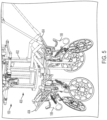
- the second attachment feature 404 is configured to support the clamp 108 and is attached to the rotation device 800 such that rotation of the rotation device 800 can maneuver the clamp 108 into a first position for mounting to the line 110 (e.g., the right-most clamp 108 shown in FIG. 5 ). Additionally, rotation of the rotation device 800 can maneuver the clamp 108 into a second position for mounting to a second line.
- the second line can be defined as the same line 110 that has had a clamp 108 mounted to the line 110 at a different location. In some embodiments, the second line is a different line than line 110.
- the base 610 can provide a mounting location for a driver 802 (e.g., a servo motor).
- the driver 802 can be used to rotate the rotation device 800 a fixed number of degrees to help ensure that a clamp 108 is at the proper location to mount to the line 110.
- a controller on the UAV 100 can receive a signal from the ground-based controller 104 to cycle the rotation device 800 to mount the next clamp 108 in sequence.
- the driver 802 can then rotate the rotation device 800 a fixed number of degrees (e.g., 90 degrees) in order to place the next clamp 108 in a position to be mounted to the line 110.
- an operator using the ground-based controller 104 shown in FIG.
- the rotation device 800 can be used such that the UAV 100 can approach the line 110 from a single orientation for each clamp mounting event. In other words, the operator or pilot of the UAV 100 does not have to consider which direction in which to orient the UAV 100 in order to mount the next clamp 108 in a mounting sequence.
- the rotation device 800 can also include over-distance guards 640 extending generally downward from the rotation device 800.
- the over-distance guards 640 can help protect the clamps 108 if the UAV 100 is driven too far toward/into the line 110.
- the over-distance guards 640 prevent the clamps 108 from being forcibly removed from the second attachment features 404 if the line 110 impacts that part of the guide 400. Any suitable number and construction style of over-distance guards 640 are contemplated.
- a connection feature 804 can include a fitting 806 configured to reliably transmit rotational force from the driver 802 (e.g., the servo motor) to the rotation device 800.
- the fitting 806 can be a splined fitting with a female spline member 808 attached to an output of the driver 802.
- the female spline member 808 is configured to cooperate with a male spline member 810 mounted to the rotation device 800.
- Any suitable device used to transmit rotational force between the driver 802 and the rotation device 800 can be used in the spirit of this disclosure.
- the guide 400 can include a quick disconnect feature 812 configured to disconnect the guide 400 from the UAV 100.
- the quick disconnect feature 812 can include the spline members 808, 810 as described above.
- the quick disconnect feature 812 can foster relatively quick replacement of a rotation device 800 after all of the clamps 108 from a first rotation device 800 have been mounted to a line 110 or multiple lines 110. An operator or pilot can relatively quickly remove the empty rotation device 800 with a rotation device 800 with a full complement of clamps 108.
- the quick disconnect feature 812 includes any plug (e.g., the male spline member 810) and socket (e.g., the female spline member 808) connector that does not require the use of traditional hand tools to operate. When connected properly, the plug and socket lock the joint effectively to resist any tensile forces that tend to pull the connector apart.
- the quick disconnect feature 812 enables the mount 402 and the rotation device 800 to be relatively easily disconnected without tools by disengaging a locking mechanism and separating the plug and socket.
- the quick disconnect feature 812 is shown with the female spline member 808 pulled upward (e.g., by using an operator's hand) against an internal spring force to release the internal lock in preparation for insertion of the male spline member 810.
- the male spline member 810 has been inserted into the female spline member 808 and the female spline member 808 has been released and has moved to a downward locked position.
- the quick disconnect feature 812 is locked and the rotation device 800 is firmly connected to the mount 402 and thus the UAV 100.
- the second attachment feature 404 is configured to attach the clamp 108 to the guide 400
- the quick disconnect feature 812 is configured to disconnect the second attachment feature 404 from the first attachment feature 612 such that the second attachment feature 404 is disconnected from the UAV 100.
- the second attachment feature 404 includes an attachment component 1100.
- the attachment component 1100 may extend outwardly from a center of the second attachment feature 404 and may be sized to fit within an attachment opening defined by the rotation device 800.
- the attachment portion 1100 may have one or more openings 1101 to allow for mechanical fasteners (not shown) to pass therethrough so as to attach the second attachment feature 404 to the rotation device 800.
- the second attachment feature 404 comprises an alignment structure 1102 that is attached to the attachment portion 1100 that will be discussed in greater detail below.
- the alignment structure 1102 configured to direct the clamp 108 to the line 110 for mounting the clamp 108 to the line 110.
- the second attachment feature 404 includes a cross-brace 1104.
- the cross-brace 1104 may be disposed between the attachment portion 1100 and the alignment structure 1102.
- the cross-brace 1104 may extend substantially perpendicular to the attachment portion 1100, with the attachment portion 1100 attached to the cross-brace 1104.
- the alignment structure 1102 may be attached to the cross-brace 1104 opposite the attachment portion 1100. That is, in some embodiments, the attachment portion 1100 may be attached to a first side of the cross-brace 1104 while the alignment structure 1102 may be attached to a second side of the cross-brace 1104.
- the cross-brace 1104 includes one or more attachment walls, such as a first attachment wall 1106 and a second attachment wall 1108.
- the first attachment wall 1106 and the second attachment wall 1108 may be attached to the cross-brace 1104 on the same side as the alignment structure 1102. In this way, the first attachment wall 1106 and the second attachment wall 1108 may be disposed between the elongated arms 1110 of the alignment structure 1102.
- the first attachment wall 1106 and the second attachment wall 1108 may extend a distance outwardly from the cross-brace 1104, and may be spaced apart to define an opening 1112 there-between.
- the first attachment wall 1106 and the second attachment wall 1108 may comprise an attachment component 1114 configured to attach the clamp 108 to the guide 400.
- the attachment component can be a first mating portion 1116 such as a protrusion or nub.
- the first mating portion 1116 may project inwardly from the first attachment wall 1106 toward the second attachment wall 1108.
- another first mating portion 1116 may project inwardly from the second attachment wall 1108 towards the first attachment wall 1106.
- the second attachment feature 404 can include an abutment wall 1118.
- the abutment wall 1118 can be attached to the cross-brace 1104, such as by extending outwardly from the cross-brace 1104.
- the abutment wall 1118 may extend substantially perpendicular to the cross-brace 1104, and may extend downwardly from the cross-brace 1104.
- the abutment wall 1118 may comprise an abutment extension 1120.
- a first end 1122 of the abutment wall 1118 may be attached to the cross-brace 1104 while a second end 1124 of the abutment wall 1118 may be attached to the abutment extension 1120.
- the abutment extension 1120 may extend substantially perpendicular to the abutment wall 1118, such as by extending in the same direction as the elongated arms 1110. In this way, as illustrated in FIG. 11 , one end of the abutment extension 1120 may be attached to the abutment wall 1118 while another end of the abutment extension 1120 may be spaced apart from the abutment wall 1118. In some embodiments, the end of the abutment extension 1120 is in closer proximity to the cross-brace 1104 than the first mating portion 1116.
- the first mating portion 1116 is configured to mate with a second mating portion (to be discussed below) of the clamp 108 to attach the clamp 108 to the second attachment feature 404.
- the first mating portion 1116 may have a non-circular shape. That is, in an example, the first mating portion 1116 may have a half-circular shape. The shape of the first mating portion 1116 can ease attachment and/or detachment of the clamp 108 from the second attachment feature 404, and thus, the guide 400.
- the clamp 108 may comprise a first jaw 1200 and a second jaw 1202 attached to the first jaw 1200.
- the first jaw 1200 and the second jaw 1202 may be movable relative to each other.
- the first jaw 1200 may extend between a gripping end 1204 and an attachment end 1206.
- the gripping end 1204 may be curved and may define one or more inner teeth, for example.
- the first jaw 1200 may extend non-linearly between the gripping end 1204 and the attachment end 1206.
- the second jaw 1202 may be attached to the first jaw 1200 and may define a gripping opening 1208.
- the second jaw 1202 may extend between a gripping end 1210 and an attachment end 1212.
- the gripping end 1210 may be curved and may define one or more inner teeth, for example. In this way, the teeth of the gripping ends 1204, 1210 may provide an increased frictional surface so as to improve the gripping of the line 110 by the clamp 108.
- the inner teeth may be covered by a relatively soft or flexible cover 1214.
- the attachment end 1212 of the second jaw 1202 may be attached to the attachment end 1206 of the first jaw 1200.
- the attachment end 1212 of the second jaw 1202 may be pivotably attached to the attachment end 1206 of the first jaw 1200. That is, the first jaw 1200 may pivot about an axis 1216 relative to the second jaw 1202.
- the axis 1216 may intersect the attachment ends 1206, 1212 of the first jaw 1200 and the second jaw 1202. In this way, the first jaw 1200 and the second jaw 1202 may move (e.g., rotate, pivot, etc.) relative to each other between an over-center position, an arrested position, and a closed position. In some embodiments, both the over-center position and the arrested position can be considered an opened position.
- the first jaw 1200 and the second jaw 1202 may receive the line 110 within the gripping opening 1208 in order to mount the clamp 108 to the line 110.
- the line 110 In the closed position, the line 110 may be gripped by the first jaw 1200 and the second jaw 1202, such that the clamp 108 may remain affixed to the line 110.
- the clamp 108 may comprise a biasing member 1218.
- the biasing member 1218 may extend between a first end 1222 and a second end 1224.
- the biasing member 1218 may comprise a spring, such as a spring that extends along a biasing member axis 1226.
- the first end 1222 of the biasing member 1218 may be attached to the first jaw 1200.
- the second end 1224 of the biasing member 1218 may be attached to the second jaw 1202.
- the biasing member 1218 is configured to at least one of: rotate the first jaw 1200 relative to the second jaw 1202 about the axis 1216 (shown in FIG. 12 ) or rotate the second jaw 1202 relative to the first jaw 1200 about the axis 1216. In this way, the biasing member 1218 may bias the first jaw 1200 and the second jaw 1202 towards a closed position (e.g., with the gripping end 1204 of the first jaw 1200 tending to move towards the gripping end 1210 of the second jaw 1202).
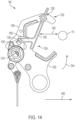
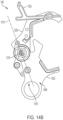
- the first jaw 1200 can be formed of two parts that sandwich the second jaw 1202. In the cross-section view of FIG. 14 , one side of the first jaw 1200 is removed to see the interaction between the components that make up the clamp 108.
- the clamp 108 includes an arresting member 1230 to selectively retain the clamp 108 in an opened position (e.g., the arrested position).
- the arresting member 1230 may hold the first jaw 1200 and the second jaw 1202 in the opened position, such that the clamp 108 may receive the line 110 within the attachment end 1206.
- the arresting member 1230 may extend along an axis between a first end 1232 and a second end 1234.
- the first end 1232 may be attached to the first jaw 1200.
- the first end 1232 may be attached at an attachment location 1236 of the first jaw 1200.
- the arresting member 1230 may be pivotably attached to the first jaw 1200, such that the arresting member 1230 may pivot relative to the first jaw 1200 about an axis 1238 (shown in FIG. 12 ).
- the second end 1234 of the arresting member 1230 may be removably attached to the first jaw 1200.
- the second end 1234 of the arresting member 1230 may comprise a first ledge 1240.
- the first ledge 1240 may comprise a protuberance, an outcropping, or the like that projects along a direction that is non-parallel (e.g., perpendicular, etc.) to an axis along which the arresting member 1230 extends.
- the first ledge 1240 may engage a second ledge 1242 that is defined on the first jaw 1200.
- the first ledge 1240 of the arresting member 1230 may rest upon the second ledge 1242 of the first jaw 1200 when the clamp 108 is in the opened, arrested position (e.g., as illustrated).
- the arresting member 1230 may be removably attached to the second jaw 1202.
- the second jaw 1202 can include a nose area 1250.
- the nose area 1250 can be formed on a relatively narrow portion of the second jaw 1202 that moves between the two halves of the first jaw 1200.
- the nose area 1250 together with the second ledge 1242, sandwiches the first ledge 1240 between the nose area 1250 and the second ledge 1242.
- the first ledge 1240 presents a physical interference preventing rotation of the first jaw 1200 relative to the second jaw 1202.
- the physical interference prevents rotation of the second jaw 1202 relative to the first jaw 1200.
- arresting member 1230 can interact with the first jaw 1200 and the second jaw 1202 to maintain the clamp 108 in the opened position (e.g., the arrested position) despite the force of the biasing member 1218 urging the clamp 108 to move toward the closed position.
- the biasing member 1218 may exert a closing force 1244 (represented by a curved arrow) on the first jaw 1200 and the second jaw 1202 to bias the clamp 108 toward the closed position.
- a closing force 1244 represented by a curved arrow
- the arresting member 1230 may maintain the clamp 108 in the opened, arrested position, with the first jaw 1200 and the second jaw 1202 spaced apart despite the bias of the biasing member 1218 toward the closed position.
- the arresting member 1230 is configured to engage at least one of the first jaw 1200 or the second jaw 1202.
- the arresting member 1230 is movable between a first position relative to at least one of the first jaw 1200 or the second jaw 1202 and a second position relative to at least one of the first jaw 1200 or the second jaw 1202.
- the arresting member 1230 is configured to at least one of: restrain rotation of the first jaw 1200 relative to the second jaw 1202 about the axis 1216 (shown in FIG. 12 ), or restrain rotation of the second jaw 1202 relative to the first jaw 1200 about the axis 1216.
- the arresting member 1230 is configured to at least one of: enable rotation of the first jaw 1200 relative to the second jaw 1202 about the axis 1216, or enable rotation of the second jaw 1202 relative to the first jaw 1200 about the axis 1216.
- the clamp 108 may be moved in a first direction 1400 toward the line 110. As the clamp 108 is moved toward the line 110, a distance 1402 between the line 110 and the arresting member 1230 may be reduced.
- the clamp 108 can be placed into an over-center position, which can aid an operator in placing the clamp 108 in the arrested position.
- the biasing member 1218 (or at least the biasing member axis 1226) will move from a first side 1408 of the axis 1216 to a second side 1410 of the axis 1216. In this position, the biasing member 1218 will thus be biasing the first jaw 1200 and the second jaw 1202 toward the opened position, rather than the closed position, and thus the clamp 108 will remain open without an external force maintaining the clamp 108 in the opened position.
- a stop or limiter may be included on at least one of the jaws 1200, 1202 to limit the rotational travel distance in the over-center position.
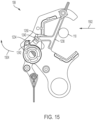
- the line 110 may eventually come into contact with the arresting member 1230 and apply a force in a second direction 1502 onto the arresting member 1230.
- This force in the second direction 1502 causes the first ledge 1240 of the arresting member 1230 to dislodge from its sandwiched location between the second ledge 1242 of the first jaw 1200 and the nose area 1250 of the second jaw 1202.
- the second end 1234 of the arresting member 1230 may therefore pivot in a backwards direction 1504.
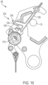
- the arresting member 1230 may not maintain the first jaw 1200 and the second jaw 1202 in the opened (e.g., arrested) position. Rather, the force of the biasing member 1218 may cause the first jaw 1200 and the second jaw 1202 to move towards each other into the closed position.
- the line 110 may be gripped between the first jaw 1200 and the second jaw 1202 to mount the clamp 108 to the line 110.
- the biasing member 1218 is configured to then maintain the clamp 108 in the closed position until it is acted upon by an outside force. As such, the clamp 108 can remain reliably mounted to the line for a relatively long time.
- the biasing member 1218 is configured to urge rotation of at least one of the first jaw 1200 or the second jaw 1202 to at least one of an over-center position, an arrested position, or a closed position.
- the biasing member 1218, or at least the biasing member axis 1406 is located on the first side 1408 of the axis 1216.
- the biasing member 1218 is located on the second side 1410 of the axis 1216.
- the first jaw 1200 may define a slot 1800 that is defined between spaced apart jaw walls of the first jaw 1200. This slot 1800 may be sized to accommodate the arresting member 1230 as the arresting member 1230 pivots in the backwards direction 1504 (shown in FIG. 15 ) and through the first jaw 1200.
- the clamp 108 is shown attached to the second attachment feature 404 of the guide 400.
- the second attachment feature 404 is configured to support the clamp 108 for mounting to the line 110 by flying, toward the line, the UAV 100 to which the guide 400 is attached as has been previously discussed.
- the attachment feature 404 includes an attachment component 1114 (shown in FIG. 11 ) configured to attach the clamp 108 to the guide 400.
- the clamp is shown in the arrested position and the clamp 108 is in position to be mounted to the line 110.
- the line 110 (not shown in this figure), has contacted the arresting member 1230.
- the resultant force between the line 110 and the arresting member 1230 causes the second end 1234 of the arresting member 1230 to leave engagement or contact with the second ledge 1242 of the first jaw 1200 and the nose area 1250 of the second jaw 1202.
- the arresting member 1230 may not maintain the first jaw 1200 and the second jaw 1202 in the opened (e.g., arrested) position, and the clamp 108 is beginning to move to the closed position.
- the backing portion 2000 is configured to exert a detachment force in the direction of arrow 2002 on the clamp 108 to forcibly detach the clamp 108 from the guide 400.
- the detachment force 2002 is a function of kinetic energy (e.g., rapid movement of the second jaw 1202 relative to the first jaw 1200) that causes the clamp 108 to move from the arrested position to the closed position. This detachment occurs as the clamp 108 moves from the arrested position to the closed position whereby a distance between a first jaw 1200 of the clamp 108 and a second jaw 1202 of the clamp 108 is decreased to mount the clamp 108 to the line 110.
- the backing portion 2000 is configured to exert the detachment force 2002 to the arresting member 1230 of the clamp 108 responsive to the arresting member 1230 contacting the backing portion 2000 as the clamp 108 moves from the arrested position to the closed position.
- the arresting member 1230 then translates the force 2002 to at least one of the first jaw 1200 or the second jaw 1202 to overcome the forces maintaining attachment between the clamp 108 and the second attachment feature 404, thus removing the clamp 108 from the second attachment feature 404 and the guide 400.
- the second attachment feature 404 can include the previously discussed abutment wall 1118 and the abutment extension 1120.
- a face 1900 of the abutment extension 1120 can contact the clamp 108 when the clamp 108 is attached to the second attachment feature 404. It is possible that the clamp 108 may have some ability to rotate about the connection with the second attachment feature 404 at the first mating portion 1116 engagement with the second mating portion 2100 of the clamp 108. However, the contact between the clamp 108 and the abutment extension 1120 helps maintain the open side 1902 of the clamp 108 at a particular angle with respect to the plane 226 (shown in FIG. 2 ).
- the contact between the clamp 108 and the abutment extension 1120 enables the guide 400 to be configured to support the clamp 108 such that an imaginary clamp line 1904 between the first jaw 1200 of the clamp 108 and the second jaw 1202 of the clamp 108 when the clamp 108 is in the arrested position is non-parallel to the plane 226 intersecting the first propeller 210, the second propeller 214, and the third propeller 218 (shown in FIG. 2 ).
- the UAV 100 can include a propeller guard 2200 that is at an angle 2202 relative to the plane 226 intersecting the first propeller 210, the second propeller 214, and the third propeller 218 to direct the clamp 108 to the line 110.
- the rotation device 800 enables the UAV 100 to approach the line 110 to mount the clamp 108 to the line 110 from a single orientation (e.g., line 2204).
- the propeller guard 2200 can extend help ensure the line 110 will not contact the propellers on the side of the UAV 100 that approaches the line 110.
- a first side 2206 of the propeller guard 2200 can be located above the propeller, and then angle to a second side 2208 of the propeller that is generally in front of the propeller (e.g., in the direction 2204 of the application of the clamp 108).
- the propeller guard 2200 then extends along a third side 2210 at an angle 2202 relative to the plane 226 to direct the clamp 108 to the line 110.
- the line 110 is shown in contact with the second side 2208 of the propeller guard 2200 to show the propeller guard 2200 inhibiting and or prohibiting contact between the line 110 and the propellers of the UAV 100.
- the line 110 is shown in contact with the third side 2210 of the propeller guard 2200 that is configured to direct the clamp 108 to the line 110.
- a force imparted to the propeller guard 2200 third side 2210 is represented by line 2400.
- the resultant forces on the UAV 100 can be represented in orthogonal directions as vertical force 2402 and horizontal force 2404.
- the resultant vertical force 2402 will urge the UAV 100 in an upward direction to direct the clamp 108 to the line 110.
- the vertical force 2402 will continue to urge the UAV 100 in an upward direction as the UAV 100 is moving in the direction toward the line 110 (e.g., direction 2406).
- the elevation view of the UAV 100 shows cooperation between the third side 2210 of the propeller guard 2200 and the alignment structure 1102 of the second attachment feature 404.
- the line 110 can contact the alignment structure 1102 to further direct the clamp 108 to the line 110.
- any gap between the third side 2210 and the alignment structure 1102 are significantly smaller than a diameter of the line 110 such that the line cannot pass between the third side 2210 and the alignment structure 1102.
- the propeller guard 2200 can include an upward facing stop 2600 extending away from the first side 2206 of the propeller guard 2200.
- the line 110 is shown in contact with the stop 2600 to demonstrate the potential of the stop 2600 to reduce and/or eliminate the possibility of the line 110 passing over a portion of the front side of the UAV 100 and making contact with the propellers on the side opposite the forward side of the UAV 100.
- the UAV 100 can include a first camera to provide visual assistance to a ground-based operator.
- the first camera can include a system of communications 106 between the UAV 100 and the ground-based controller 104 such that the first camera can relay pictures and/or moving images from an aerial location to the ground-based controller 104.
- the ground-based operator can view the images from the first camera in order to properly position the UAV 100 to align the clamp 108 to the line 110.
- the ground-based operator can view a screen on the ground-based controller to fly the UAV 100 to present the clamp 108 to the line 110 and cause contact between the clamp 108 and the line 110 to move the arresting member xxx to automatically close the clamp 108 around the line 110 to mount the clamp 108 to the line 110.
- the first camera can be mounted to face a direction toward what may be considered the "front" of the UAV 100, such that the ground-based operator can watch the line 110 as it is approached by the UAV 100 and guide the UAV 100 to the line 110.
- the UAV 100 can include a second camera mounted on an arm of the UAV 100 and facing toward the clamp 108 that is attached to the guide 400 or the second attachment feature 404.
- the second camera can include a system of communications 106 between the UAV 100 and one or more ground-based controllers.
- a second ground-based operator can view the images from the second camera on a second ground-based controller 114 (shown in FIG. 1 ) in order to limit the amount of information presented at the ground-based controller 104.
- the second camera can relay information regarding the interaction between the clamp 108 and the line 110 that may not be within the viewing range of the first camera.
- a power line protection device 1812 can be provided for protecting a power line (e.g., line 110) from animals (e.g., avifauna) and/or for protecting animals from the power line.
- the animals comprise airborne animals, such as birds, bats, etc.
- the animals may be airborne during the day and/or at night.
- the power line protection device 1812 is provided.
- the power line protection device 1812 is effective in deterring avifauna (e.g., birds, bats, and other flying creatures) from flying into the line 110 during the day and/or at night.
- the power line protection device 1812 can emit light, so as to deter avifauna (e.g., birds, bats, and other flying creatures) at night. Additionally, the power line protection device 1812 is conspicuous during the day and can reflect light, so as to deter animals during the day.
- avifauna e.g., birds, bats, and other flying creatures
- the power line protection device 1812 may be brightly colored, such as by having an orange color, yellow color, red color, etc. However, these bright colors may not be visible in low light conditions (e.g., dawn, dusk, night time). As such, one or more structures, components, etc. may be provided for reflecting and/or emitting light, with this reflected and/or emitted light being visible in low light conditions and during the day.
- the line protection device 1812 may be attached to the clamp 108.
- the line protection device 1812 may be attached in any number of ways, such as with mechanical fasteners, or the like.
- the line protection device 1812 may hang from a bottom side of the clamp 108, such that the line protection device 1812 is relatively visible by birds or other animals.
- the UAV 100 shall include a guide 2700.
- the guide 2700 includes a mount 2702, a first attachment feature 2704, and a second attachment feature 2706 configured to support a clamp 2708.
- the mount 2702 and the second attachment feature 2706 shall be attached to each other with additional components between the mount 2702 and the second attachment feature 2706, as is the case with the embodiment shown in FIG. 5 .
- the second attachment feature 2706 is attached directly to the mount 2702.
- the base 610 of the mount 2702 may define one or more attachment openings 700.
- the base 610 may define a first attachment opening 702, a second attachment opening 704, a third attachment opening 706, and/or a fourth attachment opening 708.
- the attachment openings 700 may be sized to receive the second attachment feature 2706.
- the guide 2700 does not include a rotation device, and an operator is required to orient the UAV 100 for each particular clamp 108 to be mounted to the line 110.
- the second attachment feature 2706 comprises an attachment portion 2802.
- the attachment portion 2802 may extend outwardly from a center of the second attachment feature 2706 and may be sized to fit within one of the attachment openings 700.
- the attachment portion 2802 may have one or more openings to allow for mechanical fasteners to pass there-through so as to attach the second attachment feature 2706 to the mount 2702.
- the second attachment feature 2706 comprises an alignment structure 2804 that is attached to the attachment portion 2802.
- attachment portion 2802 may extend along an axis, with the alignment structure 2804 extending non-parallel to the axis.
- the alignment structure 2804 may define an angle with respect to the axis along which the attachment portion 2802 extends. The angle may be, for example, between about 30 degrees to about 60 degrees.
- the alignment structure 2804 may comprise a pair of elongated arms 2806 that extend substantially parallel to each other, and may be attached to each other by a connection portion 2808. As will be explained above with other embodiments of the second attachment feature, the alignment structure 2804 may assist in aligning the clamp 108 to the line 110.
- the second attachment feature 2706 can include a guide structure 2900.
- the guide structure 2900 may be attached to the connection portion 2808 of the second attachment feature 2706.
- the connection portion 2808 may comprise a wall 2902 that defines a guide opening 2904 into which the guide structure 2900 may be received.
- the guide structure 2900 may extend along an axis outwardly from the second attachment feature 2706.
- the guide structure 2900 may assist a drone operator who is operating the UAV 100 to provide a point of reference relative to the UAV 100 and the line 110.
- the guide structure 2900 can include a ball at a distal end of the guide structure 2900.
- the guide 3000 comprises a mount 3002 and a rotation device 3004.
- the rotation device 3004 is configured to attach several second attachment features 2706 and is configured to rotate to present each second attachment feature 2706 sequentially to a line 110 in order to mount the clamp 108 to the line 110.
- the rotation device 3004 comprises a cover 3006 and a base 3008.
- the cover 3006 may be attached to the base 3008, with the base 3008 being movable relative to the cover 3006.
- the cover 3006 may have a top side and a bottom side. In some embodiments, the top side may face the UAV 100 while the bottom side may face the base 3008.
- the top side of the cover 3006 may comprise one or more attachment structures that assist in attaching the cover 3006 to the UAV 100.
- the cover 3006 may comprise a first attachment structure 3010, a second attachment structure 3012, a third attachment structure 3014, and a fourth attachment structure 3016.
- the first attachment structure 3010, the second attachment structure 3012, the third attachment structure 3014, and the fourth attachment structure 3016 may extend outwardly from the top side of the cover 3006.
- top surfaces of the first attachment structure 3010, the second attachment structure 3012, the third attachment structure 3014, and the fourth attachment structure 3016 may define a first plane, while remaining portions of the cover 3006 may define a second plane that is non-coplanar (e.g., offset) with respect to the first plane.
- a bottom side of the UAV 100 may comprise one or more recesses that are sized and/or shaped to receive the first attachment structure 3010, the second attachment structure 3012, the third attachment structure 3014, and the fourth attachment structure 3016.
- the cover 3006 may receive a fastener 3018 (e.g., a threaded fastener) through the cover opening defined by the cover 3006 so as to attach the cover 3006 to the UAV 100.
- a fastener 3018 e.g., a threaded fastener
- the base 3008 comprises a base wall 3100 that is surrounded by a surrounding wall 3102.
- the cover 3006 may be attached to the surrounding wall 3102 so as to define a gap, a space, a recess, or the like between the cover 3006 and the base wall 3100.
- the base wall 3100 may have a substantially rounded shape, though other shapes (e.g., square, etc.) are envisioned.
- the base 3008 comprises one or more walls that define attachment openings.
- the base 3008 may comprise a first wall 3104 that defines a first attachment opening 3106, a second wall 3108 that defines a second attachment opening 3110, a third wall 3112 that defines a third attachment opening 3114, and a fourth wall 3116 that defines a fourth attachment opening 3118.
- the first wall 3104, the second wall 3108, the third wall 3112, and the fourth wall 3116 may project outwardly from the surrounding wall 3102. In this way, ends of the first wall 3104, the second wall 3108, the third wall 3112, and the fourth wall 3116 may be spaced a distance apart from the surrounding wall 3102.
- first wall 3104, the second wall 3108, the third wall 3112, and the fourth wall 3116 may be spaced apart between about 80 degrees to about 100 degrees about the surrounding wall 3102.
- first wall 3104, the second wall 3108, the third wall 3112, and the fourth wall 3116 may be spaced apart about 90 degrees from one another.
- such a spacing may be different than as illustrated herein.
- the second attachment feature 2706 may be attached to the base 3008.
- the second attachment feature 2706 may be received within one of the attachment openings 700 in a as described herein with respect to FIG. 7 .
- the base 3008 may receive a plurality of second attachment features 2706, such as a second attachment feature 2706 within each of the first attachment opening 232, the second attachment opening 234, the third attachment opening 236, and/or the fourth attachment opening 238 (collectively attachment openings 700).
- the base 3008 may comprise a first stopper 3119 while the cover 3006 may comprise a second stopper 3120.
- the first stopper 3119 comprises a projection, protuberance, or other structure formed along an interior wall of the base 3008.
- the second stopper 3120 may comprise a projection, protuberance, or other structure formed along an interior wall of the cover 3006.
- the first stopper 3119 and the second stopper 3120 may face each other when the cover 3006 is attached to the base 3008.
- a biasing device 3122 may comprise a first biasing end 3124 and a second biasing end 3126.
- the first biasing end 3124 and the second biasing end 3126 may project outwardly from an axis (e.g. central axis 206) along which the biasing device 3122 extends. That is, in some embodiments, the biasing device 3122 may define an opening that extends along an axis, with the first biasing end 3124 and the second biasing end 3126 extending perpendicular to the axis.
- the first biasing end 3124 of the biasing device 3122 may engage the first stopper 3119 while the second biasing end 3126 of the biasing device 3122 may engage the second stopper 3120.
- a protrusion end of a protrusion may be received within an opening 3128 defined within the base 3008. In this way, due to the cover 3006 being attached to and non-movable relative to the UAV 100, the biasing device 3122 may cause the base 3008 to move relative to the cover 3006.
- the biasing device 3122 may apply a biasing force to the base 3008 to cause the base 3008 to rotate relative to the cover 3006.
- a push mechanism (not shown) may be attached to a bottom side of the base 3008.
- the push mechanism may project outwardly from a perimeter of the base 3008, and may be fixedly attached to the fastener.
- the biasing device 3122 may cause the base 3008 to move relative to the cover 3006. In operation, the base 3008 may be limited from further movement due to the clamps 108 contacting the push mechanism. Once a clamp 108 has been attached to the line 110, the force applied by the biasing device 3122 to the base 3008 may cause further rotation of the base 3008, at least until the next clamp 108 contacts the push mechanism. In this way, the base 3008 and the cover 3006 may provide an auto-indexing feature for attaching clamps 108 to one or more lines 110.
- the clamp 3300 can include a first jaw 3302, a second jaw 3304, a biasing member 3306, and an arresting member 3308, etc.
- the arresting member 3308 comprises a first arresting portion 3310 and a second arresting portion 3312.
- the first arresting portion 3310 may have a first end 3314 that is pivotably attached to the first jaw 3302.
- the second arresting portion 3312 may have a first ledge 3316 that engages a second ledge 3318 of the second jaw 3304, similar to previously described embodiments.
- the first arresting portion 3310 and the second arresting portion 3312 may be attached by an arresting pivot 3320. In this way, the first arresting portion 3310 and the second arresting portion 3312 may pivot relative to each other about the arresting pivot 3320.
- the second arresting portion 3312 comprises a stop member 3400.
- the stop member 3400 may selectively abut the first arresting portion 3310.
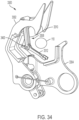
- the arresting member 3308 is movable between an extended position (e.g., as illustrated in FIG. 33 ) in which the first arresting portion 3310 and the second arresting portion 3312 extend along an axis 3402, and a folded position (e.g. as illustrated in FIG. 34 ) in which the first arresting portion 3310 and the second arresting portion 3312 extend non-linearly with respect to each other.
- the stop member 3400 may limit the arresting member 3308 from moving to the folded position by abutting the first arresting portion 3310.
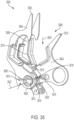
- the clamp 3500 may comprise a first jaw 3502, a second jaw 3504, a biasing member 3506, and an arresting member 3508.
- the arresting member 3508 may extend non-linearly between opposing ends. For example, a center portion 3510 of the arresting member 3508 may form an angle.
- the arresting member 3508 includes a first ledge 3518.
- the first ledge 3518 may comprise a protuberance, an outcropping, or the like.
- the first ledge 3518 may engage a second ledge 3520 that is defined in the first jaw 3502.
- the first jaw 3502 may define an opening in which the second ledge 3520 may be formed.
- the second ledge 3520 may be formed adjacent to an axis 3522.
- the axis 3522 and the second ledge 3520 may be located on a same side (e.g., below) the location of the pivotable attachment between the arresting member 3508 and the second jaw 3504.
- the second ledge 3520 may comprise a shelf, an outcropping, or the like.
- the first ledge 3518 of the arresting member 3508 may rest upon the second ledge 3520 of the first jaw 3502 when the clamp 3500 is in the opened position (e.g., as illustrated in FIG. 35 ).
- the biasing member 3506 may exert a closing force 3524 on the first jaw 3502 and the second jaw 3504 to bias the clamp 3500 towards the closed position.
- the arresting member 3508 may maintain the clamp 3500 in the opened position, with the first jaw 3502 and the second jaw 3504 spaced apart.
- the clamp 3600 can include a first jaw 3602, a second jaw 3604, a biasing member 3606, and an arresting member 3608.
- the arresting member 3608 may be disposed at a rear of the first jaw 3602.
- the arresting member 3608 may be removably attached to the first jaw 3602 at the attachment location 3610.
- the arresting member 3608 can extend between a first end 3612 and a second end 3614.
- the first end 3612 may be removably attached to the first jaw 3602.
- the first jaw 3602 may define a second ledge 3616 that is formed between the walls that define a slot 3618.
- the first end 3612 of the arresting member 3608 may engage and rest upon the second ledge 3616.
- the second jaw 3604 comprises a stopper 3620.
- the stopper 3620 may be positioned within the slot 3618.
- the arresting member 3608 may initially be inserted within the slot 3618 so as to rest upon the second ledge 3616.
- the stopper 3620 may contact and engage the arresting member 3608.
- the second ledge 3616 may be disposed on a first side 3622 of the arresting member 3608 while the stopper 3620 may be disposed on an opposing second side of the arresting member 3608.
- the arresting member 3608 may be moved in a direction away from the clamp 3600 such that the arresting member 3608 may be removed from the second ledge 3616. As the arresting member 3608 is removed from the second ledge 3616, the stopper 3620 may no longer contact and/or engage the arresting member 3608. In this way, the arresting member 3608 may not maintain the first jaw 3602 and the second jaw 3604 in the opened position. Rather, the force of the biasing member 3606 may cause the first jaw 3602 and the second jaw 3604 to move towards each other into the closed position. In this way, the line 110 may be gripped between the first jaw 3602 and the second jaw 3604.
- the clamp 3700 can include a first jaw 3702, a second jaw 3704, a biasing member 3706, and an arresting member 3708.
- the arresting member 3708 may be disposed at a rear of the first jaw 3702.
- the arresting member 3708 comprises one or more arresting arms.
- the arresting member 3708 comprises a first arresting arm 3710, a second arresting arm 3712, and a third arresting arm 3714.
- the first arresting arm 3710 may extend from a rear of the second jaw 3704 and through a slot 3716 defined by the first jaw 3702.
- the second arresting arm 3712 may be pivotably attached to the first arresting arm 3710 at a first pivot attachment 3718. In this way, the first arresting arm 3710 and the second arresting arm 3712 may pivot relative to each other.
- the arresting member 3708 includes the third arresting arm 3714 that is pivotably attached to the second arresting arm 3712 at a second pivot attachment 3720. In this way, the second arresting arm 3712 and the third arresting arm 3714 may pivot relative to each other. Opposite the second pivot attachment 3720, the third arresting arm 3714 may be attached to the first jaw 3702.
- the first jaw 3702 comprises a stopper 3722 that extends between the walls that define the slot 3716.
- the second arresting arm 3712 and/or the third arresting arm 3714 may abut and/or contact the stopper 3722.
- the arresting member 3708 may be moved in a direction away from the stopper 3722.
- the second arresting arm 3712 may comprise a gripping location 3726 that is adjacent to the second pivot attachment 3720. A force may be applied to the gripping location 3726 to move the second arresting arm 3712 away from the stopper 3722.
- the third arresting arm 3714 may likewise move away from the stopper 3722. With the second arresting arm 3712 and the third arresting arm 3714 moving away from the stopper, the first arresting arm 3710 may move towards the third arresting arm 3714 (e.g., downwardly).
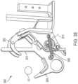
- the clamp 3800 can include a first jaw 3802, a second jaw 3804, and a biasing member 3806.
- the clamp 3800 may not include an arresting member. Rather, the position of the biasing member 3806 may maintain the clamp 3800 in an opened position versus a closed position.
- the biasing member 3806 may be located on a side of the axis 3814, such as by being located below the axis 3814. In this way, the biasing member 3806 may apply a force to the first jaw 3802 and the second jaw 3804. However, due to the biasing member 3806 being located below the axis 3814, the first jaw 3802 and the second jaw 3804 may remain in the opened position. In other words, the biasing member 3806 is urging the first jaw 3802 and the second jaw 3804 to the opened position because the clamp 3800 is in an over-center position.
- the clamp 3800 may be moved into proximity to the line 110.
- the line 110 may contact a jaw wall 3810 of the second jaw 3804.
- Contact between the line 110 and the jaw wall 3810 of the second jaw 3804 may provide a sufficient amount of force for the second jaw 3804 to overcome the biasing force of the biasing member 3806.
- the second jaw 3804 may begin to rotate relative to the first jaw 3802. This rotation may allow for the biasing member 3806 to move upwards such that, the biasing member 3806 may be located on an opposite side of the axis 3814 (e.g., above the axis).
- the biasing member 3806 may no longer maintain the first jaw 3802 and the second jaw 3804 in the opened position. Rather, the force of the biasing member 3806 may cause the first jaw 3802 and the second jaw 3804 to move towards each other into the closed position. In this way, the line 110 may be gripped between the first jaw 3802 and the second jaw 3804.
- the clamp 3900 can include a first jaw 3902, a second jaw 3904, and a biasing member 3906.
- the illustrated clamp of FIG. 39 is similar to the clamp 3800 of FIG. 38 .
- the clamp 3900 can include a disengagement structure, such as a wheel 3910.
- the wheel 3910 may be rotatably attached to the first jaw 3902.
- the line 110 may engage a leg 3912 of the wheel 3910.
- Such an engagement may cause the wheel 3910 to rotate.
- one or more legs 3912 of the wheel 3910 may contact a mounting structure (not shown) to which the clamp 3900 is mounted. This contact may assist in releasing the clamp 3900 from the mounting structure.
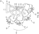
- mounting structure 4000 is illustrated for mounting the clamps 4002 to a line 110.
- the mounting structure 4000 may comprise a base 4004 and a wheel 4006.
- the base 4004 may be attached to the UAV 100, while the wheel 4006 may be attached to the base 4004.
- the mounting structure 4000 comprises a mounting arm 4008 that is movable relative to the wheel 4006.
- the mounting arm 4008 may extend between a gear end 4010 and an engagement end 4012.
- the gear end 4010 may be located in proximity to a center of the wheel 4006 while the engagement end 4012 may be located towards a perimeter of the wheel 4006.
- the gear end 4010 may comprise a stopper 4014 for engaging with gears 4016 of the wheel 4006.
- the gears 4016 define one or more slots, openings, or the like that are formed in a portion of the wheel 4006.
- the mounting arm 4008 may normally be biased to a position in which the engagement end 4012 is in contact with the wheel 4006 and the gear end 4010 is located a distance away from the gears 4016.
- the wheel 4006 may pivot downwardly as represented by arrow 4020.
- the engagement end 4012 may receive a portion of the clamp 4002, such as a wall 4018.
- a wall of the clamp 4002 may be positioned between the engagement end of the mounting arm 4008 and the wheel 4006.
- the outwardly flared shape of the engagement end 4012 may further facilitate receiving a portion of the clamp 4002.
- the gear end 4010 of the mounting arm 4008 may move into engagement with the gears 4016. That is, the stopper 4014 of the mounting arm 4008 may pivot so as to be received within one of the gear openings of the gear 4016. With the stopper 4014 in place, the wheel 4006 is substantially limited from inadvertently rotating. However, once a clamp 4002 has received a line and the clamp is disengaged from the wheel 4006, the wheel 4006 may rotate, thus positioning the next clamp 4002 in place relative to the line 110.
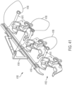
- a mounting structure 4100 for mounting a set of clamps 4102 to a line 110.
- the mounting structure 4100 may comprise a frame 4104 and a clamp holder 4106.
- one or more of the clamps 4102 may be attached to the clamp holder 4106.
- the frame 4104 may be attached to the UAV 100, such that the clamps 4102 may be transported towards the line 110.
- the mounting structure 4100 comprises a wire 4108 that may be attached to the frame 4104 and to a triggering mechanism 4110 of the clamps 4102.
- one of the clamps 4102 may be attached to a line 110.
- the wire 4108 may cause the triggering mechanism 4110 to disengage from the clamp 4102 and, thus, cause the clamp 4102 to move from the opened position to the closed position.
- the clamp 4102 may be attached to the line 110.
- gravity may assist in causing the next clamp 4102 to slide down the clamp holder 4106 towards an end 4112 of the clamp holder 4106.
- an unmanned aerial vehicle e.g., a drone
- a line e.g., overhead conductor
- an auto-triggering clamp is described to enable the clamp to automatically latch onto the line by using kinetic energy that has been converted from potential energy in a biasing member as the clamp triggers itself through contact with a line.
- a carrier system has also been developed to work with available commercial drones to enable the clamp to be carried to the line and then be released once the clamp has latched onto the line. This system may replace conventional bucket truck or helicopter installation methods.
- the drone pilot may mount the drone guide to the drone. Then, the pilot may install a clamp into the carrier and set a trigger so that the clamp may be ready to be installed on a line.
- Some drone guides shall be capable of holding multiple clamps to help accelerate the installation process of multiple clamps (e.g., drone does not have to return to ground for every clamp).
- the pilot shall power up the drone and navigate up to the line.
- the pilot may then maneuver the drone so that the clamp is driven into the line which shall trip the trigger and close the clamp around the line.
- the clamp shall (e.g., nearly) simultaneously release from the guide and shall remain fixed to the line while the pilot navigates the drone to the next install location.
- the pilot shall land the drone and repeat the installation process until all of the clamps have been installed.
- first,” “second,” or the like are not intended to imply a temporal aspect, a spatial aspect, an ordering, etc. Rather, such terms are merely used as identifiers, names, etc. for features, elements, items, etc.
- a first component and a second component correspond to component A and component B or two different or two identical components or the same component.
- exemplary is used herein to mean serving as an example, instance, illustration, etc., and not necessarily as advantageous.
- “or” is intended to mean an inclusive “or” rather than an exclusive “or”.
- “a” and “an” as used in this application are to be construed to mean “one or more” unless specified otherwise or clear from context to be directed to a singular form.
- at least one of A and B or the like means A or B or both A and B.
Landscapes
- Engineering & Computer Science (AREA)
- Mechanical Engineering (AREA)
- General Engineering & Computer Science (AREA)
- Aviation & Aerospace Engineering (AREA)
- Remote Sensing (AREA)
- Clamps And Clips (AREA)
- Catching Or Destruction (AREA)
- Snaps, Bayonet Connections, Set Pins, And Snap Rings (AREA)
- Forklifts And Lifting Vehicles (AREA)
Description
- The instant application is directed towards an unmanned aerial vehicle. For example, the instant application is directed toward an unmanned aerial vehicle for mounting a clamp to a line.
- Unmanned aerial vehicles may be used for mounting a clamp. Unmanned aerial vehicles may be used to mount a clamp to a line.
- The article entitled:" Mitigating avian collision with power lines: a proof of concept for installation of line makers via unmanned aerial vehicle", Journal of Unmanned Vehicle Systems, Vol 3 N°4, 1 december 2015, pages 252-258, the video extract entitled "Ako pracuje specialny drone od syker engineering" published on You tube media on 11 november 2016, and the article of Rick Harness entitled: " Using unmanned aerial vehicles to install wire markers to mitigate bird collisions ENV-VISION: environmental vision" on 25 may 2016 disclose such vehicles.
- The subject matter of the invention is as claimed in appended
claim 1. Optional features are disclosed in dependent claims 2-6. - The following description and annexed drawings set forth certain illustrative aspects and implementations. These are indicative of but a few of the various ways in which one or more aspects may be employed. Other aspects, advantages, and/or novel features of the disclosure will become apparent from the following detailed description when considered in conjunction with the annexed drawings.
-
-
FIG. 1 is an illustration of a clamp mounting system including an unmanned aerial vehicle near a line; -
FIG. 2 is an illustration of an unmanned aerial vehicle; -
FIG. 3 is an illustration of an unmanned aerial vehicle; -
FIG. 4 is an illustration of an unmanned aerial vehicle; -
FIG. 5 is an illustration of a guide with a clamp; -
FIG. 6 is an illustration of an example guide without clamps; -
FIG. 7 is an illustration of an example mounting assembly; -
FIG. 8 is an illustration of an example mounting assembly; -
FIG. 9 is an illustration of an example mounting assembly; -
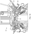
FIG. 10 is an illustration of an example mounting assembly; -
FIG. 11 is an illustration of an example second attachment feature; -
FIG. 12 is an illustration of an example clamp; -
FIG. 13 is an illustration of an example clamp; -
FIG. 14 is an illustration of an example clamp; -
FIG. 15 is an illustration of an example clamp; -
FIG. 16 is an illustration of an example clamp; -
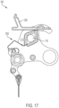
FIG. 17 is an illustration of an example clamp; -
FIG. 18 is an illustration of an example clamp; -
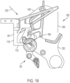
FIG. 19 is an illustration of an example clamp; -
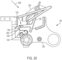
FIG. 20 is an illustration of an example clamp; -
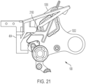
FIG. 21 is an illustration of an example clamp; -
FIG. 22 is an illustration of an example propeller guard; -
FIG. 23 is an illustration of an example propeller guard -
FIG. 24 is an illustration of an example propeller guard; -
FIG. 25 is an illustration of an example propeller guard -
FIG. 26 is an illustration of an example propeller guard; -
FIG. 27 is an illustration of an example unmanned aerial vehicle; -
FIG. 28 is an illustration of an example second attachment feature; -
FIG. 29 is an illustration of an example second attachment feature; -
FIG. 30 is an illustration of an example mounting assembly; -
FIG. 31 is an illustration of an example mounting assembly; -
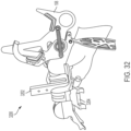
FIG. 32 is an illustration of an example clamp; -
FIG. 33 is an illustration of an example clamp; -
FIG. 34 is an illustration of an example clamp; -
FIG. 35 is an illustration of an example clamp; -
FIG. 36 is an illustration of an example clamp; -
FIG. 37 is an illustration of an example clamp; -
FIG. 38 is an illustration of an example clamp; -
FIG. 39 is an illustration of an example clamp; -
FIG. 40 is an illustration of an example clamp mounting assembly; and -
FIG. 41 is an illustration of an example clamp mounting assembly. - The claimed subject matter is now described with reference to the drawings, wherein like reference numerals are used to refer to like elements throughout. In the following description, for purposes of explanation, numerous specific details are set forth in order to provide an understanding of the claimed subject matter. It is evident, however, that the claimed subject matter may be practiced without these specific details. In other instances, structures and devices are illustrated in block diagram form in order to facilitate describing the claimed subject matter. Relative size, orientation, etc. of parts, components, etc. may differ from that which is illustrated while not falling outside of the scope of the claimed subject matter.
- The present disclosure relates to supporting clamps in flight and mounting clamps to lines using an unmanned aerial vehicle (UAV). For the purposes of the present disclosure, the terms unmanned aerial vehicle, UAV, and drone can be used interchangeably to indicate an aircraft without a human pilot onboard. UAVs can be a component of an unmanned aircraft system (UAS); which can include a UAV, a ground-based controller, and a system of communications between the UAV and the ground-based controller. UAVs may operate and/or fly with various degrees of autonomy, for example, fly under remote control by a human operator, fly autonomously by onboard computers, or fly using a combination of the two.
- While there are many different styles of UAVs in use, some common features of UAVs include a body, propellers to develop lift, an electric motor-driven propulsion apparatus attached to the UAV (e.g., attached to the body), and a rechargeable electrical battery apparatus attached to the UAV. The description and figures within this disclosure relate to a UAV having six propellers attached to arms extending radially away from the body of the UAV, however, this is not meant to be limiting, and various styles, sizes, and propulsion systems are contemplated for use with the present disclosure.
- Referring to
FIG. 1 , an overview of an unmanned aerial vehicle (UAV) 100 in an application environment is illustrated. TheUAV 100 can be one part of aclamp attachment system 102 that also includes (as noted previously) a ground-basedcontroller 104, and a system ofcommunications 106 between theUAV 100 and the ground-basedcontroller 104. - The
UAV 100 as part of theclamp attachment system 102 shall be used to mount or attach aclamp 108 to aline 110. For the purposes of the present disclosure, the line can include, but is not limited to: an overhead conductor, a power line, a cable, a wire, a rope, a cord, a grounding/bonding device, etc. Theline 110 may be positioned at a location that is not easily accessible, such as a distance above the ground, as shown inFIG. 1 . Theline 110 shall comprise an overhead power line such that theline 110 is generally inaccessible (difficult to access, e.g., workers may need a helicopter or bucket truck to access the overhead conductor).Line 110 shall be used in electric power transmission networks to transmit electrical energy. Theline 110 can comprise one or more overhead conductors that are suspended by towers and/orpoles 112. In this way, theUAV 100 may be piloted or flown a distance above the ground, whereupon theUAV 100 is able to mount theclamp 108 to theline 110. - Referring to
FIG. 2 , a perspective view of theUAV 100 is illustrated according to some embodiments. TheUAV 100 includes abody 200. Thebody 200 can be a basic framework for mounting various components of theUAV 100, such as a controller (not shown),rechargeable batteries 202, anantenna 204 to receive communications from the ground-based controller 104 (shown inFIG. 1 ), etc. In some embodiments, thebody 200 can be centered about acentral axis 206. Thebody 200 can also provide a mounting location for afirst arm 208 configured to mount afirst propeller 210 at a distance from thebody 200. As such, thefirst propeller 210 is attached to thebody 200 through thefirst arm 208. Similarly, asecond arm 212 is attached to thebody 200 and provides a mount for asecond propeller 214 to be attached to thebody 200. Athird arm 216 is also attached to thebody 200 and provides a mount for athird propeller 218 that is attached to thebody 200. - The
body 200 is between at least one of thefirst propeller 210 and thesecond propeller 214, thefirst propeller 210 and thethird propeller 218, or thesecond propeller 214 and thethird propeller 218. In some embodiments, the meaning of thebody 200 being between a number of propellers is that the propellers are on opposing sides of theUAV 100. In some embodiments, the meaning of thebody 200 being between a number of propellers is that the propellers are attached to arms and the path of attachment between the propellers extends from one propeller, through an arm, through the body, and finally through another arm to another propeller. A geometric construct of aplane 226 can also be described that intersects thefirst propeller 210, thesecond propeller 214, and thethird propeller 218. In some embodiments, for ease of description, theplane 226 can be defined by the center points of thepropellers - Referring to
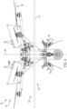
FIG. 3 , a top, or plan, view of theUAV 100 proximate theline 110 is illustrated. As previously discussed, the figures collectively show aUAV 100 having six propellers in a particular orientation (e.g., generally within a single plane and oriented in a hexagonal fashion as shown inFIG. 3 ), however, theUAV 100 can include any suitable number and arrangement of propellers. - Referring to
FIG. 4 , a side, or elevation, view of theUAV 100 is illustrated in proximity to theline 110. It is also to be understood that each of the propellers can be canted such that the axis of rotation of each propeller is not parallel to thecentral axis 206, but angles toward thecentral axis 206 as the axis of rotation extends upward and away from theUAV 100. Canting of the propellers in this way can increase the airborne stability of theUAV 100. - Returning to
FIG. 2 , thebody 200 of theUAV 100 has afirst side 220 and asecond side 222. Asupport structure 224 is attached to thefirst side 220 of thebody 200, for example, a pair of legs. Thesupport structure 224 is configured to support theUAV 100 on a surface (e.g., the ground, a work surface, etc.) when theUAV 100 is not flying. In some embodiments, thesupport structure 224 can be rotated about a mounting joint at thebody 200 duringUAV 100 flight. - Returning to
FIG. 4 , aguide 400 is attached to thefirst side 220 of thebody 200. Thefirst side 220 is the side of thebody 200 that faces downward, or toward the ground. Theguide 400 is configured to support theclamp 108 for mounting theclamp 108 to theline 110 by flying theUAV 100 toward theline 110. Theguide 400 is configured to support theclamp 108 for mounting theclamp 108 to theline 110 by flying theUAV 100 toward theline 110 and causing contact between theclamp 108 and theline 110. - Referring to
FIG. 5 , a detail view of theguide 400 is shown with theclamp 108 attached to theguide 400. Theguide 400 includes a mount 402 a first attachment feature, and asecond attachment feature 404. In some embodiments, themount 402 and thesecond attachment feature 404 may be attached to each other with additional components between themount 402 and thesecond attachment feature 404, as is the case with the embodiment shown inFIG. 5 . In some embodiments, thesecond attachment feature 404 is attached directly to themount 402, as will be discussed below. Regardless of the attachment arrangement between thesecond attachment feature 404 and themount 402, themount 402 can be attached to theUAV 100, while thesecond attachment feature 404 can be attached to theclamp 108. - Referring to
FIG. 6 , a detail view of theguide 400 is shown with theclamp 108 removed from theguide 400 and thesupport structure 224 removed from thebody 200 for clarity. Themount 402 of theguide 400 is shown as mounted to thefirst side 220 of thebody 200. In some embodiments, themount 402 comprises one ormore columns 600. For example, themount 402 may comprise afirst column 602, asecond column 604, athird column 606, and/or afourth column 608. Thefirst column 602, thesecond column 604, thethird column 606, and/or thefourth column 608 may be spaced apart and may extend substantially parallel to one another. In some embodiments, thefirst column 602, thesecond column 604, thethird column 606, and/or thefourth column 608 may be spaced apart to form a rectangular shape, though, other shapes are envisioned. Additionally, first ends of thefirst column 602, thesecond column 604, thethird column 606, and/or thefourth column 608 may be attached to abase 610. - Referring to
FIG. 7 , a detail view of themount 402 is illustrated. Opposing second ends of thefirst column 602, thesecond column 604, thethird column 606, and/or thefourth column 608 may include thefirst attachment feature 612. In some embodiments, thefirst attachment feature 612 may comprise afirst locking bracket 614, asecond locking bracket 616, athird locking bracket 618, and/or afourth locking bracket 620. Thefirst locking bracket 614 may be attached to thefirst column 602. Thesecond locking bracket 616 may be attached to thesecond column 604. Thethird locking bracket 618 may be attached to thethird column 606. Thefourth locking bracket 620 may be attached to thefourth column 608. - The first attachment feature 612 (e.g., the locking
brackets mount 402 to theUAV 100. In some embodiments, the lockingbrackets UAV 100 may be received, such as arail UAV 100, for example. In this way, the lockingbrackets first locking bracket 614 and thesecond locking bracket 616 receiving a first rail 624 (shown inFIG. 6 ) of theUAV 100, and thethird locking bracket 618 and thefourth locking bracket 620 receiving a second rail 626 (shown inFIG. 6 ) of theUAV 100. As such, in some embodiments, thefirst attachment feature 612 may function to removably attach themount 402 of theguide 400 to theUAV 100. - Returning to
FIG. 7 , in some embodiments, themount 402 comprises one or more lateral supports 628 that may extend between thecolumns lateral support 630, a secondlateral support 632, a thirdlateral support 634, and/or a fourthlateral support 636. The firstlateral support 630 may extend between thefirst column 602 and thesecond column 604. The secondlateral support 632 may extend between thethird column 606 and thefourth column 608. The thirdlateral support 634 may extend between thesecond column 604 and thefourth column 608. The fourthlateral support 636 may extend between thefirst column 602 and thethird column 606. In some embodiments, the lateral supports 630, 632, 634, 636 may extend in a direction that is non-parallel to thecolumns columns lateral support 630 may extend substantially parallel to the secondlateral support 632. In some embodiments, the thirdlateral support 634 may extend substantially parallel to the fourthlateral support 636. In this way, the ends of the lateral supports 630, 632, 634, 636 may be attached to therespective columns columns - The
mount 402 can also include thebase 610. In some embodiments, thebase 610 is attached to an end of thecolumns first attachment feature 612. In this way, thebase 610 is spaced a distance apart from theUAV 100. The base 610 may provide additional support to thecolumns 602, 604,606, 608 so as to limit unintended vibration, flexing, deformation, or the like. - Referring to
FIG. 8 , theUAV 100 includes arotation device 800 configured to rotate about an axis (e.g., the central axis 206) that is perpendicular to the plane 226 (shown inFIG. 2 ). Therotation device 800 can also be termed a clamp carrier. Thesecond attachment feature 404 is configured to support theclamp 108 and is attached to therotation device 800 such that rotation of therotation device 800 can maneuver theclamp 108 into a first position for mounting to the line 110 (e.g., theright-most clamp 108 shown inFIG. 5 ). Additionally, rotation of therotation device 800 can maneuver theclamp 108 into a second position for mounting to a second line. In some embodiments, the second line can be defined as thesame line 110 that has had aclamp 108 mounted to theline 110 at a different location. In some embodiments, the second line is a different line thanline 110. - In some embodiments, the base 610 can provide a mounting location for a driver 802 (e.g., a servo motor). The
driver 802 can be used to rotate the rotation device 800 a fixed number of degrees to help ensure that aclamp 108 is at the proper location to mount to theline 110. In some embodiments, a controller on theUAV 100 can receive a signal from the ground-basedcontroller 104 to cycle therotation device 800 to mount thenext clamp 108 in sequence. Thedriver 802 can then rotate the rotation device 800 a fixed number of degrees (e.g., 90 degrees) in order to place thenext clamp 108 in a position to be mounted to theline 110. In some embodiments, an operator using the ground-based controller 104 (shown inFIG. 1 ) can use a single motion (e.g., depress a button), in order to cause thedriver 802 to rotate therotation device 800 to the next position. It is worthy of note that therotation device 800 can be used such that theUAV 100 can approach theline 110 from a single orientation for each clamp mounting event. In other words, the operator or pilot of theUAV 100 does not have to consider which direction in which to orient theUAV 100 in order to mount thenext clamp 108 in a mounting sequence. - Returning to
FIG. 6 , therotation device 800 can also includeover-distance guards 640 extending generally downward from therotation device 800. Theover-distance guards 640 can help protect theclamps 108 if theUAV 100 is driven too far toward/into theline 110. For example, theover-distance guards 640 prevent theclamps 108 from being forcibly removed from the second attachment features 404 if theline 110 impacts that part of theguide 400. Any suitable number and construction style ofover-distance guards 640 are contemplated. - Returning to
FIG. 8 , aconnection feature 804 can include a fitting 806 configured to reliably transmit rotational force from the driver 802 (e.g., the servo motor) to therotation device 800. In some embodiments, the fitting 806 can be a splined fitting with afemale spline member 808 attached to an output of thedriver 802. Thefemale spline member 808 is configured to cooperate with amale spline member 810 mounted to therotation device 800. Any suitable device used to transmit rotational force between thedriver 802 and therotation device 800 can be used in the spirit of this disclosure. - Additionally, the
guide 400 can include aquick disconnect feature 812 configured to disconnect theguide 400 from theUAV 100. Thequick disconnect feature 812 can include thespline members quick disconnect feature 812 can foster relatively quick replacement of arotation device 800 after all of theclamps 108 from afirst rotation device 800 have been mounted to aline 110 ormultiple lines 110. An operator or pilot can relatively quickly remove theempty rotation device 800 with arotation device 800 with a full complement ofclamps 108. - For the purposes of this disclosure, the
quick disconnect feature 812 includes any plug (e.g., the male spline member 810) and socket (e.g., the female spline member 808) connector that does not require the use of traditional hand tools to operate. When connected properly, the plug and socket lock the joint effectively to resist any tensile forces that tend to pull the connector apart. Thequick disconnect feature 812 enables themount 402 and therotation device 800 to be relatively easily disconnected without tools by disengaging a locking mechanism and separating the plug and socket. - Referring to
FIG. 9 , thequick disconnect feature 812 is shown with thefemale spline member 808 pulled upward (e.g., by using an operator's hand) against an internal spring force to release the internal lock in preparation for insertion of themale spline member 810. - Referring to
FIG. 10 , themale spline member 810 has been inserted into thefemale spline member 808 and thefemale spline member 808 has been released and has moved to a downward locked position. In this position, thequick disconnect feature 812 is locked and therotation device 800 is firmly connected to themount 402 and thus theUAV 100. As described, thesecond attachment feature 404 is configured to attach theclamp 108 to theguide 400, and thequick disconnect feature 812 is configured to disconnect thesecond attachment feature 404 from thefirst attachment feature 612 such that thesecond attachment feature 404 is disconnected from theUAV 100. - Referring to
FIG. 11 , a perspective view of asecond attachment feature 404 is shown in detail. Thesecond attachment feature 404 includes anattachment component 1100. Theattachment component 1100 may extend outwardly from a center of thesecond attachment feature 404 and may be sized to fit within an attachment opening defined by therotation device 800. In some embodiments, theattachment portion 1100 may have one ormore openings 1101 to allow for mechanical fasteners (not shown) to pass therethrough so as to attach thesecond attachment feature 404 to therotation device 800. - The
second attachment feature 404 comprises analignment structure 1102 that is attached to theattachment portion 1100 that will be discussed in greater detail below. Thealignment structure 1102 configured to direct theclamp 108 to theline 110 for mounting theclamp 108 to theline 110. In some embodiments, thesecond attachment feature 404 includes across-brace 1104. The cross-brace 1104 may be disposed between theattachment portion 1100 and thealignment structure 1102. In some embodiments, thecross-brace 1104 may extend substantially perpendicular to theattachment portion 1100, with theattachment portion 1100 attached to thecross-brace 1104. In some embodiments, thealignment structure 1102 may be attached to the cross-brace 1104 opposite theattachment portion 1100. That is, in some embodiments, theattachment portion 1100 may be attached to a first side of the cross-brace 1104 while thealignment structure 1102 may be attached to a second side of thecross-brace 1104. - The
cross-brace 1104 includes one or more attachment walls, such as afirst attachment wall 1106 and asecond attachment wall 1108. Thefirst attachment wall 1106 and thesecond attachment wall 1108 may be attached to thecross-brace 1104 on the same side as thealignment structure 1102. In this way, thefirst attachment wall 1106 and thesecond attachment wall 1108 may be disposed between theelongated arms 1110 of thealignment structure 1102. Thefirst attachment wall 1106 and thesecond attachment wall 1108 may extend a distance outwardly from thecross-brace 1104, and may be spaced apart to define anopening 1112 there-between. In some embodiments, thefirst attachment wall 1106 and thesecond attachment wall 1108 may comprise anattachment component 1114 configured to attach theclamp 108 to theguide 400. In some embodiments, the attachment component can be afirst mating portion 1116 such as a protrusion or nub. For example, thefirst mating portion 1116 may project inwardly from thefirst attachment wall 1106 toward thesecond attachment wall 1108. Although hidden inFIG. 11 , anotherfirst mating portion 1116 may project inwardly from thesecond attachment wall 1108 towards thefirst attachment wall 1106. - Remaining with
FIG. 11 , thesecond attachment feature 404 can include anabutment wall 1118. In an example, theabutment wall 1118 can be attached to thecross-brace 1104, such as by extending outwardly from thecross-brace 1104. For example, theabutment wall 1118 may extend substantially perpendicular to thecross-brace 1104, and may extend downwardly from thecross-brace 1104. Theabutment wall 1118 may comprise anabutment extension 1120. In some embodiments, afirst end 1122 of theabutment wall 1118 may be attached to thecross-brace 1104 while asecond end 1124 of theabutment wall 1118 may be attached to theabutment extension 1120. Theabutment extension 1120 may extend substantially perpendicular to theabutment wall 1118, such as by extending in the same direction as theelongated arms 1110. In this way, as illustrated inFIG. 11 , one end of theabutment extension 1120 may be attached to theabutment wall 1118 while another end of theabutment extension 1120 may be spaced apart from theabutment wall 1118. In some embodiments, the end of theabutment extension 1120 is in closer proximity to the cross-brace 1104 than thefirst mating portion 1116. - In some embodiments, the
first mating portion 1116 is configured to mate with a second mating portion (to be discussed below) of theclamp 108 to attach theclamp 108 to thesecond attachment feature 404. Thefirst mating portion 1116 may have a non-circular shape. That is, in an example, thefirst mating portion 1116 may have a half-circular shape. The shape of thefirst mating portion 1116 can ease attachment and/or detachment of theclamp 108 from thesecond attachment feature 404, and thus, theguide 400. - Referring to
FIG. 12 , a perspective view of theclamp 108 is illustrated. Theclamp 108 may comprise afirst jaw 1200 and asecond jaw 1202 attached to thefirst jaw 1200. Thefirst jaw 1200 and thesecond jaw 1202 may be movable relative to each other. Thefirst jaw 1200 may extend between agripping end 1204 and anattachment end 1206. Thegripping end 1204 may be curved and may define one or more inner teeth, for example. In some embodiments, thefirst jaw 1200 may extend non-linearly between thegripping end 1204 and theattachment end 1206. - The
second jaw 1202 may be attached to thefirst jaw 1200 and may define agripping opening 1208. In some embodiments, thesecond jaw 1202 may extend between agripping end 1210 and anattachment end 1212. Thegripping end 1210 may be curved and may define one or more inner teeth, for example. In this way, the teeth of the gripping ends 1204, 1210 may provide an increased frictional surface so as to improve the gripping of theline 110 by theclamp 108. In some embodiments, the inner teeth may be covered by a relatively soft orflexible cover 1214. - The
attachment end 1212 of thesecond jaw 1202 may be attached to theattachment end 1206 of thefirst jaw 1200. In some embodiments, theattachment end 1212 of thesecond jaw 1202 may be pivotably attached to theattachment end 1206 of thefirst jaw 1200. That is, thefirst jaw 1200 may pivot about anaxis 1216 relative to thesecond jaw 1202. In some embodiments, theaxis 1216 may intersect the attachment ends 1206, 1212 of thefirst jaw 1200 and thesecond jaw 1202. In this way, thefirst jaw 1200 and thesecond jaw 1202 may move (e.g., rotate, pivot, etc.) relative to each other between an over-center position, an arrested position, and a closed position. In some embodiments, both the over-center position and the arrested position can be considered an opened position. In the opened position, thefirst jaw 1200 and thesecond jaw 1202 may receive theline 110 within thegripping opening 1208 in order to mount theclamp 108 to theline 110. In the closed position, theline 110 may be gripped by thefirst jaw 1200 and thesecond jaw 1202, such that theclamp 108 may remain affixed to theline 110. - Referring to
FIG. 13 , in order to assist in moving thefirst jaw 1200 and thesecond jaw 1202 between the opened and the closed positions, theclamp 108 may comprise a biasingmember 1218. The biasingmember 1218 may extend between afirst end 1222 and asecond end 1224. In some embodiments, the biasingmember 1218 may comprise a spring, such as a spring that extends along a biasingmember axis 1226. Thefirst end 1222 of the biasingmember 1218 may be attached to thefirst jaw 1200. Thesecond end 1224 of the biasingmember 1218 may be attached to thesecond jaw 1202. In some embodiments, the biasingmember 1218 is configured to at least one of: rotate thefirst jaw 1200 relative to thesecond jaw 1202 about the axis 1216 (shown inFIG. 12 ) or rotate thesecond jaw 1202 relative to thefirst jaw 1200 about theaxis 1216. In this way, the biasingmember 1218 may bias thefirst jaw 1200 and thesecond jaw 1202 towards a closed position (e.g., with thegripping end 1204 of thefirst jaw 1200 tending to move towards thegripping end 1210 of the second jaw 1202). - Referring to
FIG. 14 , in some embodiments, thefirst jaw 1200 can be formed of two parts that sandwich thesecond jaw 1202. In the cross-section view ofFIG. 14 , one side of thefirst jaw 1200 is removed to see the interaction between the components that make up theclamp 108. Theclamp 108 includes an arrestingmember 1230 to selectively retain theclamp 108 in an opened position (e.g., the arrested position). For example, the arrestingmember 1230 may hold thefirst jaw 1200 and thesecond jaw 1202 in the opened position, such that theclamp 108 may receive theline 110 within theattachment end 1206. In some embodiments, the arrestingmember 1230 may extend along an axis between afirst end 1232 and asecond end 1234. Thefirst end 1232 may be attached to thefirst jaw 1200. For example, thefirst end 1232 may be attached at anattachment location 1236 of thefirst jaw 1200. In some embodiments, the arrestingmember 1230 may be pivotably attached to thefirst jaw 1200, such that the arrestingmember 1230 may pivot relative to thefirst jaw 1200 about an axis 1238 (shown inFIG. 12 ). - The
second end 1234 of the arrestingmember 1230 may be removably attached to thefirst jaw 1200. For example, thesecond end 1234 of the arrestingmember 1230 may comprise afirst ledge 1240. Thefirst ledge 1240 may comprise a protuberance, an outcropping, or the like that projects along a direction that is non-parallel (e.g., perpendicular, etc.) to an axis along which the arrestingmember 1230 extends. In some embodiments, thefirst ledge 1240 may engage asecond ledge 1242 that is defined on thefirst jaw 1200. For example, thefirst ledge 1240 of the arrestingmember 1230 may rest upon thesecond ledge 1242 of thefirst jaw 1200 when theclamp 108 is in the opened, arrested position (e.g., as illustrated). - Also, while in the arrested position, the arresting
member 1230 may be removably attached to thesecond jaw 1202. For example, thesecond jaw 1202 can include anose area 1250. In some embodiments, thenose area 1250 can be formed on a relatively narrow portion of thesecond jaw 1202 that moves between the two halves of thefirst jaw 1200. As shown, thenose area 1250, together with thesecond ledge 1242, sandwiches thefirst ledge 1240 between thenose area 1250 and thesecond ledge 1242. As such, thefirst ledge 1240 presents a physical interference preventing rotation of thefirst jaw 1200 relative to thesecond jaw 1202. Similarly, the physical interference prevents rotation of thesecond jaw 1202 relative to thefirst jaw 1200. This is only one example of how the arrestingmember 1230 can interact with thefirst jaw 1200 and thesecond jaw 1202 to maintain theclamp 108 in the opened position (e.g., the arrested position) despite the force of the biasingmember 1218 urging theclamp 108 to move toward the closed position. - In the opened, arrested position as shown in
FIG. 14 , the biasingmember 1218 may exert a closing force 1244 (represented by a curved arrow) on thefirst jaw 1200 and thesecond jaw 1202 to bias theclamp 108 toward the closed position. When the arrestingmember 1230 is in contact with the second jaw 1202 (e.g., by virtue of thenose area 1250 resting upon the first ledge 1240), the arrestingmember 1230 may maintain theclamp 108 in the opened, arrested position, with thefirst jaw 1200 and thesecond jaw 1202 spaced apart despite the bias of the biasingmember 1218 toward the closed position. - As described, the arresting
member 1230 is configured to engage at least one of thefirst jaw 1200 or thesecond jaw 1202. The arrestingmember 1230 is movable between a first position relative to at least one of thefirst jaw 1200 or thesecond jaw 1202 and a second position relative to at least one of thefirst jaw 1200 or thesecond jaw 1202. In the first position, the arrestingmember 1230 is configured to at least one of: restrain rotation of thefirst jaw 1200 relative to thesecond jaw 1202 about the axis 1216 (shown inFIG. 12 ), or restrain rotation of thesecond jaw 1202 relative to thefirst jaw 1200 about theaxis 1216. In the second position, the arrestingmember 1230 is configured to at least one of: enable rotation of thefirst jaw 1200 relative to thesecond jaw 1202 about theaxis 1216, or enable rotation of thesecond jaw 1202 relative to thefirst jaw 1200 about theaxis 1216. - Remaining with
FIG. 14 , theclamp 108 may be moved in afirst direction 1400 toward theline 110. As theclamp 108 is moved toward theline 110, adistance 1402 between theline 110 and the arrestingmember 1230 may be reduced. - Referring to
FIG. 14B , theclamp 108 can be placed into an over-center position, which can aid an operator in placing theclamp 108 in the arrested position. As shown, if thefirst jaw 1200 and thesecond jaw 1202 are a suitable number of degrees away from each other, the biasing member 1218 (or at least the biasing member axis 1226) will move from afirst side 1408 of theaxis 1216 to asecond side 1410 of theaxis 1216. In this position, the biasingmember 1218 will thus be biasing thefirst jaw 1200 and thesecond jaw 1202 toward the opened position, rather than the closed position, and thus theclamp 108 will remain open without an external force maintaining theclamp 108 in the opened position. It is understood that a stop or limiter may be included on at least one of thejaws - Referring to
FIG. 15 , theline 110 may eventually come into contact with the arrestingmember 1230 and apply a force in asecond direction 1502 onto the arrestingmember 1230. This force in thesecond direction 1502 causes thefirst ledge 1240 of the arrestingmember 1230 to dislodge from its sandwiched location between thesecond ledge 1242 of thefirst jaw 1200 and thenose area 1250 of thesecond jaw 1202. Thesecond end 1234 of the arrestingmember 1230 may therefore pivot in abackwards direction 1504. - Referring to
FIG. 16 , as a result of thesecond end 1234 of the arrestingmember 1230 no longer contacting thesecond ledge 1242 of thefirst jaw 1200 and thenose area 1250 of thesecond jaw 1202, the arrestingmember 1230 may not maintain thefirst jaw 1200 and thesecond jaw 1202 in the opened (e.g., arrested) position. Rather, the force of the biasingmember 1218 may cause thefirst jaw 1200 and thesecond jaw 1202 to move towards each other into the closed position. - Referring to
FIG. 17 , in this way, theline 110 may be gripped between thefirst jaw 1200 and thesecond jaw 1202 to mount theclamp 108 to theline 110. The biasingmember 1218 is configured to then maintain theclamp 108 in the closed position until it is acted upon by an outside force. As such, theclamp 108 can remain reliably mounted to the line for a relatively long time. - As a summary of the
clamp 108 positions, the biasingmember 1218 is configured to urge rotation of at least one of thefirst jaw 1200 or thesecond jaw 1202 to at least one of an over-center position, an arrested position, or a closed position. When thefirst jaw 1200 and thesecond jaw 1202 are in the over-center position, the biasingmember 1218, or at least the biasing member axis 1406 is located on thefirst side 1408 of theaxis 1216. When thefirst jaw 1200 and thesecond jaw 1202 are in the closed position, the biasingmember 1218 is located on thesecond side 1410 of theaxis 1216. - Referring to
FIG. 18 , in some embodiments, thefirst jaw 1200 may define aslot 1800 that is defined between spaced apart jaw walls of thefirst jaw 1200. Thisslot 1800 may be sized to accommodate the arrestingmember 1230 as the arrestingmember 1230 pivots in the backwards direction 1504 (shown inFIG. 15 ) and through thefirst jaw 1200. - Referring to
FIG. 19 , theclamp 108 is shown attached to thesecond attachment feature 404 of theguide 400. Thesecond attachment feature 404 is configured to support theclamp 108 for mounting to theline 110 by flying, toward the line, theUAV 100 to which theguide 400 is attached as has been previously discussed. Theattachment feature 404 includes an attachment component 1114 (shown inFIG. 11 ) configured to attach theclamp 108 to theguide 400. InFIG. 19 , the clamp is shown in the arrested position and theclamp 108 is in position to be mounted to theline 110. - Referring to
FIG. 20 , the line 110 (not shown in this figure), has contacted the arrestingmember 1230. The resultant force between theline 110 and the arrestingmember 1230 causes thesecond end 1234 of the arrestingmember 1230 to leave engagement or contact with thesecond ledge 1242 of thefirst jaw 1200 and thenose area 1250 of thesecond jaw 1202. As a result of thesecond end 1234 of the arrestingmember 1230 no longer contacting thesecond ledge 1242 of thefirst jaw 1200 and thenose area 1250 of thesecond jaw 1202, the arrestingmember 1230 may not maintain thefirst jaw 1200 and thesecond jaw 1202 in the opened (e.g., arrested) position, and theclamp 108 is beginning to move to the closed position. - Also in
FIG. 20 , thesecond attachment feature 404 includes a backing portion 2000. In some embodiments, the backing portion 2000 is angled and is configured to be impacted by the arrestingmember 1230. As the biasing member 1218 (not shown) forces thesecond jaw 1202 to rotate relative to thefirst jaw 1200, aportion 1252 of the second jaw 1202 (shown inFIG. 17 ) strikes the arrestingmember 1230 with significant force. This force propels the arresting member 1230 (e.g., the first ledge 1240) into contact with the backing portion 2000 as the arrestingmember 1230 rotates. - The backing portion 2000 is configured to exert a detachment force in the direction of
arrow 2002 on theclamp 108 to forcibly detach theclamp 108 from theguide 400. Thedetachment force 2002 is a function of kinetic energy (e.g., rapid movement of thesecond jaw 1202 relative to the first jaw 1200) that causes theclamp 108 to move from the arrested position to the closed position. This detachment occurs as theclamp 108 moves from the arrested position to the closed position whereby a distance between afirst jaw 1200 of theclamp 108 and asecond jaw 1202 of theclamp 108 is decreased to mount theclamp 108 to theline 110. - The backing portion 2000 is configured to exert the
detachment force 2002 to the arrestingmember 1230 of theclamp 108 responsive to the arrestingmember 1230 contacting the backing portion 2000 as theclamp 108 moves from the arrested position to the closed position. The arrestingmember 1230 then translates theforce 2002 to at least one of thefirst jaw 1200 or thesecond jaw 1202 to overcome the forces maintaining attachment between theclamp 108 and thesecond attachment feature 404, thus removing theclamp 108 from thesecond attachment feature 404 and theguide 400. - Referring to
FIG. 21 , as previously discussed, thesecond attachment feature 404 includes anattachment component 1100 includes a first mating portion 1116 (shown inFIG. 11 ) configured to mate with asecond mating portion 2100 of theclamp 108 to attach theclamp 108 to theguide 400. In some embodiments, thesecond mating portion 2100 is an aperture defined by a portion of thefirst jaw 1200. It is to be understood that the first mating portion 1116 (e.g., the protrusion on the second attachment feature 404) can be located instead on theclamp 108 and the second mating portion 2100 (e.g., the aperture defined by the clamp 108) can be located on thesecond attachment feature 404. In order to ease the forcible, automatic removal of theclamp 108 instantaneously with the mounting of theclamp 108 to theline 110, theattachment component 1100 can be elastically deformable to attach theclamp 108 to theguide 400. - Returning to
FIG. 19 , thesecond attachment feature 404 can include the previously discussedabutment wall 1118 and theabutment extension 1120. In some embodiments, aface 1900 of theabutment extension 1120 can contact theclamp 108 when theclamp 108 is attached to thesecond attachment feature 404. It is possible that theclamp 108 may have some ability to rotate about the connection with thesecond attachment feature 404 at thefirst mating portion 1116 engagement with thesecond mating portion 2100 of theclamp 108. However, the contact between theclamp 108 and theabutment extension 1120 helps maintain theopen side 1902 of theclamp 108 at a particular angle with respect to the plane 226 (shown inFIG. 2 ). - The contact between the
clamp 108 and theabutment extension 1120 enables theguide 400 to be configured to support theclamp 108 such that animaginary clamp line 1904 between thefirst jaw 1200 of theclamp 108 and thesecond jaw 1202 of theclamp 108 when theclamp 108 is in the arrested position is non-parallel to theplane 226 intersecting thefirst propeller 210, thesecond propeller 214, and the third propeller 218 (shown inFIG. 2 ). - Referring to
FIG. 22 , theUAV 100 can include apropeller guard 2200 that is at anangle 2202 relative to theplane 226 intersecting thefirst propeller 210, thesecond propeller 214, and thethird propeller 218 to direct theclamp 108 to theline 110. As has been discussed, therotation device 800 enables theUAV 100 to approach theline 110 to mount theclamp 108 to theline 110 from a single orientation (e.g., line 2204). Thepropeller guard 2200 can extend help ensure theline 110 will not contact the propellers on the side of theUAV 100 that approaches theline 110. Afirst side 2206 of thepropeller guard 2200 can be located above the propeller, and then angle to asecond side 2208 of the propeller that is generally in front of the propeller (e.g., in thedirection 2204 of the application of the clamp 108). Thepropeller guard 2200 then extends along athird side 2210 at anangle 2202 relative to theplane 226 to direct theclamp 108 to theline 110. In some examples there may be an intermediatepropeller guard portion 2212 between thesecond side 2208 and thethird side 2210. - Referring to
FIG. 23 , theline 110 is shown in contact with thesecond side 2208 of thepropeller guard 2200 to show thepropeller guard 2200 inhibiting and or prohibiting contact between theline 110 and the propellers of theUAV 100. - Referring to
FIG. 24 , theline 110 is shown in contact with thethird side 2210 of thepropeller guard 2200 that is configured to direct theclamp 108 to theline 110. At contact, a force imparted to thepropeller guard 2200third side 2210 is represented byline 2400. The resultant forces on theUAV 100 can be represented in orthogonal directions asvertical force 2402 andhorizontal force 2404. The resultantvertical force 2402 will urge theUAV 100 in an upward direction to direct theclamp 108 to theline 110. Thevertical force 2402 will continue to urge theUAV 100 in an upward direction as theUAV 100 is moving in the direction toward the line 110 (e.g., direction 2406). - Referring to
FIG. 25 , the elevation view of theUAV 100 shows cooperation between thethird side 2210 of thepropeller guard 2200 and thealignment structure 1102 of thesecond attachment feature 404. As theline 110 passes away from the end of thethird side 2210 of thepropeller guard 2200, theline 110 can contact thealignment structure 1102 to further direct theclamp 108 to theline 110. In some embodiments, any gap between thethird side 2210 and thealignment structure 1102 are significantly smaller than a diameter of theline 110 such that the line cannot pass between thethird side 2210 and thealignment structure 1102. - Referring to
FIG. 26 , thepropeller guard 2200 can include anupward facing stop 2600 extending away from thefirst side 2206 of thepropeller guard 2200. InFIG. 26 , theline 110 is shown in contact with thestop 2600 to demonstrate the potential of thestop 2600 to reduce and/or eliminate the possibility of theline 110 passing over a portion of the front side of theUAV 100 and making contact with the propellers on the side opposite the forward side of theUAV 100. - In some embodiments, the
UAV 100 can include a first camera to provide visual assistance to a ground-based operator. For example, the first camera can include a system ofcommunications 106 between theUAV 100 and the ground-basedcontroller 104 such that the first camera can relay pictures and/or moving images from an aerial location to the ground-basedcontroller 104. The ground-based operator can view the images from the first camera in order to properly position theUAV 100 to align theclamp 108 to theline 110. In some embodiments, the ground-based operator can view a screen on the ground-based controller to fly theUAV 100 to present theclamp 108 to theline 110 and cause contact between theclamp 108 and theline 110 to move the arresting member xxx to automatically close theclamp 108 around theline 110 to mount theclamp 108 to theline 110. In general, the first camera can be mounted to face a direction toward what may be considered the "front" of theUAV 100, such that the ground-based operator can watch theline 110 as it is approached by theUAV 100 and guide theUAV 100 to theline 110. - Additionally, the
UAV 100 can include a second camera mounted on an arm of theUAV 100 and facing toward theclamp 108 that is attached to theguide 400 or thesecond attachment feature 404. The second camera can include a system ofcommunications 106 between theUAV 100 and one or more ground-based controllers. In some embodiments, a second ground-based operator can view the images from the second camera on a second ground-based controller 114 (shown inFIG. 1 ) in order to limit the amount of information presented at the ground-basedcontroller 104. The second camera can relay information regarding the interaction between theclamp 108 and theline 110 that may not be within the viewing range of the first camera. - Returning to
FIG. 18 , A powerline protection device 1812 can be provided for protecting a power line (e.g., line 110) from animals (e.g., avifauna) and/or for protecting animals from the power line. In some embodiments, the animals comprise airborne animals, such as birds, bats, etc. In some examples, the animals may be airborne during the day and/or at night. To limit animal contact with theline 110, the powerline protection device 1812 is provided. The powerline protection device 1812 is effective in deterring avifauna (e.g., birds, bats, and other flying creatures) from flying into theline 110 during the day and/or at night. For example, the powerline protection device 1812 can emit light, so as to deter avifauna (e.g., birds, bats, and other flying creatures) at night. Additionally, the powerline protection device 1812 is conspicuous during the day and can reflect light, so as to deter animals during the day. - In some embodiments, the power
line protection device 1812 may be brightly colored, such as by having an orange color, yellow color, red color, etc. However, these bright colors may not be visible in low light conditions (e.g., dawn, dusk, night time). As such, one or more structures, components, etc. may be provided for reflecting and/or emitting light, with this reflected and/or emitted light being visible in low light conditions and during the day. - In some embodiments, the
line protection device 1812 may be attached to theclamp 108. Theline protection device 1812 may be attached in any number of ways, such as with mechanical fasteners, or the like. In some embodiments, theline protection device 1812 may hang from a bottom side of theclamp 108, such that theline protection device 1812 is relatively visible by birds or other animals. - Referring to
FIG. 27 , theUAV 100 shall include aguide 2700. Theguide 2700 includes amount 2702, a first attachment feature 2704, and asecond attachment feature 2706 configured to support a clamp 2708.Themount 2702 and thesecond attachment feature 2706 shall be attached to each other with additional components between themount 2702 and thesecond attachment feature 2706, as is the case with the embodiment shown inFIG. 5 . However, in the embodiment inFIG. 27 , thesecond attachment feature 2706 is attached directly to themount 2702. - As shown in
FIG. 7 , thebase 610 of themount 2702 may define one ormore attachment openings 700. For example, thebase 610 may define a first attachment opening 702, a second attachment opening 704, a third attachment opening 706, and/or a fourth attachment opening 708. Theattachment openings 700 may be sized to receive thesecond attachment feature 2706. In some embodiments, theguide 2700 does not include a rotation device, and an operator is required to orient theUAV 100 for eachparticular clamp 108 to be mounted to theline 110. - Referring to
FIG. 28 , asecond attachment feature 2706 according to some embodiments is illustrated. In these embodiments, thesecond attachment feature 2706 comprises anattachment portion 2802. Theattachment portion 2802 may extend outwardly from a center of thesecond attachment feature 2706 and may be sized to fit within one of theattachment openings 700. Theattachment portion 2802 may have one or more openings to allow for mechanical fasteners to pass there-through so as to attach thesecond attachment feature 2706 to themount 2702. - The
second attachment feature 2706 comprises analignment structure 2804 that is attached to theattachment portion 2802. In some embodiments,attachment portion 2802 may extend along an axis, with thealignment structure 2804 extending non-parallel to the axis. In some embodiments, thealignment structure 2804 may define an angle with respect to the axis along which theattachment portion 2802 extends. The angle may be, for example, between about 30 degrees to about 60 degrees. In some embodiments, thealignment structure 2804 may comprise a pair ofelongated arms 2806 that extend substantially parallel to each other, and may be attached to each other by aconnection portion 2808. As will be explained above with other embodiments of the second attachment feature, thealignment structure 2804 may assist in aligning theclamp 108 to theline 110. - Referring to
FIG. 29 , in some embodiments, thesecond attachment feature 2706 can include aguide structure 2900. In some embodiments, theguide structure 2900 may be attached to theconnection portion 2808 of thesecond attachment feature 2706. Theconnection portion 2808 may comprise awall 2902 that defines aguide opening 2904 into which theguide structure 2900 may be received. In this way, theguide structure 2900 may extend along an axis outwardly from thesecond attachment feature 2706. Theguide structure 2900 may assist a drone operator who is operating theUAV 100 to provide a point of reference relative to theUAV 100 and theline 110. In some embodiments, theguide structure 2900 can include a ball at a distal end of theguide structure 2900. - Referring to
FIG. 30 , aguide 3000 according to some embodiments is illustrated. Theguide 3000 comprises amount 3002 and arotation device 3004. Therotation device 3004 is configured to attach several second attachment features 2706 and is configured to rotate to present eachsecond attachment feature 2706 sequentially to aline 110 in order to mount theclamp 108 to theline 110. - The
rotation device 3004 comprises acover 3006 and abase 3008. In some embodiments, thecover 3006 may be attached to thebase 3008, with thebase 3008 being movable relative to thecover 3006. Thecover 3006 may have a top side and a bottom side. In some embodiments, the top side may face theUAV 100 while the bottom side may face thebase 3008. - In some embodiments, the top side of the
cover 3006 may comprise one or more attachment structures that assist in attaching thecover 3006 to theUAV 100. For example, thecover 3006 may comprise afirst attachment structure 3010, asecond attachment structure 3012, athird attachment structure 3014, and afourth attachment structure 3016. In some embodiments, thefirst attachment structure 3010, thesecond attachment structure 3012, thethird attachment structure 3014, and thefourth attachment structure 3016 may extend outwardly from the top side of thecover 3006. In this way, top surfaces of thefirst attachment structure 3010, thesecond attachment structure 3012, thethird attachment structure 3014, and thefourth attachment structure 3016 may define a first plane, while remaining portions of thecover 3006 may define a second plane that is non-coplanar (e.g., offset) with respect to the first plane. It is to be appreciated that a bottom side of theUAV 100 may comprise one or more recesses that are sized and/or shaped to receive thefirst attachment structure 3010, thesecond attachment structure 3012, thethird attachment structure 3014, and thefourth attachment structure 3016. - The
cover 3006 may receive a fastener 3018 (e.g., a threaded fastener) through the cover opening defined by thecover 3006 so as to attach thecover 3006 to theUAV 100. - Referring to
FIG. 31 , thebase 3008 according to some embodiments is illustrated. In some embodiments, thebase 3008 comprises abase wall 3100 that is surrounded by a surroundingwall 3102. Thecover 3006 may be attached to the surroundingwall 3102 so as to define a gap, a space, a recess, or the like between thecover 3006 and thebase wall 3100. In some embodiments, thebase wall 3100 may have a substantially rounded shape, though other shapes (e.g., square, etc.) are envisioned. - In some embodiments, the
base 3008 comprises one or more walls that define attachment openings. For example, thebase 3008 may comprise afirst wall 3104 that defines afirst attachment opening 3106, asecond wall 3108 that defines a second attachment opening 3110, athird wall 3112 that defines athird attachment opening 3114, and afourth wall 3116 that defines afourth attachment opening 3118. In some embodiments, thefirst wall 3104, thesecond wall 3108, thethird wall 3112, and thefourth wall 3116 may project outwardly from the surroundingwall 3102. In this way, ends of thefirst wall 3104, thesecond wall 3108, thethird wall 3112, and thefourth wall 3116 may be spaced a distance apart from the surroundingwall 3102. In some embodiments, thefirst wall 3104, thesecond wall 3108, thethird wall 3112, and thefourth wall 3116 may be spaced apart between about 80 degrees to about 100 degrees about the surroundingwall 3102. For example, thefirst wall 3104, thesecond wall 3108, thethird wall 3112, and thefourth wall 3116 may be spaced apart about 90 degrees from one another. However, in other examples, such a spacing may be different than as illustrated herein. - In some embodiments, the
second attachment feature 2706 may be attached to thebase 3008. For example, thesecond attachment feature 2706 may be received within one of theattachment openings 700 in a as described herein with respect toFIG. 7 . In this way, thebase 3008 may receive a plurality of second attachment features 2706, such as asecond attachment feature 2706 within each of the first attachment opening 232, the second attachment opening 234, the third attachment opening 236, and/or the fourth attachment opening 238 (collectively attachment openings 700). - Remaining with
FIG. 31 , thebase 3008 may comprise afirst stopper 3119 while thecover 3006 may comprise asecond stopper 3120. In some embodiments, thefirst stopper 3119 comprises a projection, protuberance, or other structure formed along an interior wall of thebase 3008. Thesecond stopper 3120 may comprise a projection, protuberance, or other structure formed along an interior wall of thecover 3006. In some embodiments, thefirst stopper 3119 and thesecond stopper 3120 may face each other when thecover 3006 is attached to thebase 3008. - In some embodiments, a
biasing device 3122 may comprise afirst biasing end 3124 and asecond biasing end 3126. Thefirst biasing end 3124 and thesecond biasing end 3126 may project outwardly from an axis (e.g. central axis 206) along which thebiasing device 3122 extends. That is, in some embodiments, thebiasing device 3122 may define an opening that extends along an axis, with thefirst biasing end 3124 and thesecond biasing end 3126 extending perpendicular to the axis. - When the
cover 3006 is attached to thebase 3008, thefirst biasing end 3124 of thebiasing device 3122 may engage thefirst stopper 3119 while thesecond biasing end 3126 of thebiasing device 3122 may engage thesecond stopper 3120. For example, a protrusion end of a protrusion may be received within an opening 3128 defined within thebase 3008. In this way, due to thecover 3006 being attached to and non-movable relative to theUAV 100, thebiasing device 3122 may cause thebase 3008 to move relative to thecover 3006. For example, with thefirst biasing end 3124 of thebiasing device 3122 engaging thefirst stopper 3119 and thesecond biasing end 3126 of thebiasing device 3122 engaging thesecond stopper 3120, thebiasing device 3122 may apply a biasing force to thebase 3008 to cause thebase 3008 to rotate relative to thecover 3006. - In some embodiments, a push mechanism (not shown) may be attached to a bottom side of the
base 3008. The push mechanism may project outwardly from a perimeter of thebase 3008, and may be fixedly attached to the fastener. In some embodiments, thebiasing device 3122 may cause thebase 3008 to move relative to thecover 3006. In operation, thebase 3008 may be limited from further movement due to theclamps 108 contacting the push mechanism. Once aclamp 108 has been attached to theline 110, the force applied by thebiasing device 3122 to thebase 3008 may cause further rotation of thebase 3008, at least until thenext clamp 108 contacts the push mechanism. In this way, thebase 3008 and thecover 3006 may provide an auto-indexing feature for attachingclamps 108 to one ormore lines 110. - Referring to
FIG. 32 , aguide 3200 according to some embodiments is illustrated. In some embodiments, theguide 3200 comprises afirst attachment portion 3202 and asecond attachment portion 3204. Aclamp 108 may be received by thefirst attachment portion 3202 and thesecond attachment portion 3204. In some embodiments, theguide 3200 is configured to receive a plurality ofclamps 108, such as four clamps, for example. - Referring to
FIG. 33 and34 , aclamp 3300 is illustrated according to some embodiments. In some embodiments, theclamp 3300 can include afirst jaw 3302, asecond jaw 3304, a biasingmember 3306, and an arrestingmember 3308, etc. In some embodiments, the arrestingmember 3308 comprises afirst arresting portion 3310 and asecond arresting portion 3312. Thefirst arresting portion 3310 may have afirst end 3314 that is pivotably attached to thefirst jaw 3302. Thesecond arresting portion 3312 may have afirst ledge 3316 that engages asecond ledge 3318 of thesecond jaw 3304, similar to previously described embodiments. In some embodiments, the first arrestingportion 3310 and thesecond arresting portion 3312 may be attached by an arrestingpivot 3320. In this way, the first arrestingportion 3310 and thesecond arresting portion 3312 may pivot relative to each other about the arrestingpivot 3320. - As illustrated in
FIG. 34 , thesecond arresting portion 3312 comprises astop member 3400. Thestop member 3400 may selectively abut the first arrestingportion 3310. In some embodiments, the arrestingmember 3308 is movable between an extended position (e.g., as illustrated inFIG. 33 ) in which the first arrestingportion 3310 and thesecond arresting portion 3312 extend along anaxis 3402, and a folded position (e.g. as illustrated inFIG. 34 ) in which the first arrestingportion 3310 and thesecond arresting portion 3312 extend non-linearly with respect to each other. In some embodiments, when the first arrestingportion 3310 and thesecond arresting portion 3312 are in the extended position, thestop member 3400 may limit the arrestingmember 3308 from moving to the folded position by abutting the first arrestingportion 3310. - In operation, the arresting
member 3308 may maintain thefirst jaw 3302 and thesecond jaw 3304 in the opened position when the arrestingmember 3308 is in the extended position. When theline 110 contacts the arrestingmember 3308, the first arrestingportion 3310 and thesecond arresting portion 3312 may pivot from the extended position to the folded position (e.g., as illustrated inFIG. 34 ). With the arrestingmember 3308 in the folded position, the biasingmember 3306 may move theclamp 3300 from the opened position to the closed position. - Referring to
FIG. 35 , some embodiments of theclamp 3500 is illustrated. In some embodiments, theclamp 3500 may comprise afirst jaw 3502, asecond jaw 3504, a biasingmember 3506, and an arrestingmember 3508. In some embodiments, the arrestingmember 3508 may extend non-linearly between opposing ends. For example, acenter portion 3510 of the arrestingmember 3508 may form an angle. - The arresting
member 3508 may be pivotably attached to thesecond jaw 3504 at theattachment location 3512. In some embodiments, the arrestingmember 3508 may be attached to thesecond jaw 3504 at a location that is between afirst end 3514 and asecond end 3516 of the arrestingmember 3508. For example, a location towards acenter 3510 of the arrestingmember 3508 may be pivotably attached to thesecond jaw 3504, such that the arrestingmember 3508 may pivot relative to thesecond jaw 3504. - In some embodiments, the arresting
member 3508 includes afirst ledge 3518. Thefirst ledge 3518 may comprise a protuberance, an outcropping, or the like. Thefirst ledge 3518 may engage asecond ledge 3520 that is defined in thefirst jaw 3502. For example, thefirst jaw 3502 may define an opening in which thesecond ledge 3520 may be formed. In some embodiments, thesecond ledge 3520 may be formed adjacent to anaxis 3522. In such some embodiments, theaxis 3522 and thesecond ledge 3520 may be located on a same side (e.g., below) the location of the pivotable attachment between the arrestingmember 3508 and thesecond jaw 3504. In some embodiments, thesecond ledge 3520 may comprise a shelf, an outcropping, or the like. - In operation, the
first ledge 3518 of the arrestingmember 3508 may rest upon thesecond ledge 3520 of thefirst jaw 3502 when theclamp 3500 is in the opened position (e.g., as illustrated inFIG. 35 ). In the opened position, the biasingmember 3506 may exert aclosing force 3524 on thefirst jaw 3502 and thesecond jaw 3504 to bias theclamp 3500 towards the closed position. When the arrestingmember 3508 is in contact with the second jaw 3504 (e.g., by virtue of thefirst ledge 3518 resting upon the second ledge 3520), the arrestingmember 3508 may maintain theclamp 3500 in the opened position, with thefirst jaw 3502 and thesecond jaw 3504 spaced apart. - Referring to
FIG. 36 , aclamp 3600 according to some embodiments is illustrated. In some embodiments, theclamp 3600 can include afirst jaw 3602, asecond jaw 3604, a biasingmember 3606, and an arrestingmember 3608. In some embodiments, the arrestingmember 3608 may be disposed at a rear of thefirst jaw 3602. - In some embodiments, the arresting
member 3608 may be removably attached to thefirst jaw 3602 at the attachment location 3610. The arrestingmember 3608 can extend between a first end 3612 and a second end 3614. The first end 3612 may be removably attached to thefirst jaw 3602. For example, thefirst jaw 3602 may define asecond ledge 3616 that is formed between the walls that define aslot 3618. The first end 3612 of the arrestingmember 3608 may engage and rest upon thesecond ledge 3616. In some embodiments, thesecond jaw 3604 comprises a stopper 3620. The stopper 3620 may be positioned within theslot 3618. The arrestingmember 3608 may initially be inserted within theslot 3618 so as to rest upon thesecond ledge 3616. Opposite thesecond ledge 3616, the stopper 3620 may contact and engage the arrestingmember 3608. In this way, thesecond ledge 3616 may be disposed on a first side 3622 of the arrestingmember 3608 while the stopper 3620 may be disposed on an opposing second side of the arrestingmember 3608. - In operation, the arresting
member 3608 may rest upon thesecond ledge 3616 of thefirst jaw 3602 when theclamp 3600 is in the opened position (e.g., as illustrated). In the opened position, the biasingmember 3606 may exert a closing force 3624 on thefirst jaw 3602 and thesecond jaw 3604 to bias theclamp 3600 towards the closed position. When the arrestingmember 3608 is in contact with the stopper 3620, the arrestingmember 3608 may maintain theclamp 3600 in the opened position, with thefirst jaw 3602 and thesecond jaw 3604 spaced apart. - The arresting
member 3608 may be moved in a direction away from theclamp 3600 such that the arrestingmember 3608 may be removed from thesecond ledge 3616. As the arrestingmember 3608 is removed from thesecond ledge 3616, the stopper 3620 may no longer contact and/or engage the arrestingmember 3608. In this way, the arrestingmember 3608 may not maintain thefirst jaw 3602 and thesecond jaw 3604 in the opened position. Rather, the force of the biasingmember 3606 may cause thefirst jaw 3602 and thesecond jaw 3604 to move towards each other into the closed position. In this way, theline 110 may be gripped between thefirst jaw 3602 and thesecond jaw 3604. - Referring to
FIG. 37 , aclamp 3700 according to some embodiments is illustrated. Theclamp 3700 can include afirst jaw 3702, asecond jaw 3704, a biasingmember 3706, and an arrestingmember 3708. In some embodiments, the arrestingmember 3708 may be disposed at a rear of thefirst jaw 3702. - In some embodiments, the arresting
member 3708 comprises one or more arresting arms. For example, the arrestingmember 3708 comprises afirst arresting arm 3710, asecond arresting arm 3712, and athird arresting arm 3714. Thefirst arresting arm 3710 may extend from a rear of thesecond jaw 3704 and through aslot 3716 defined by thefirst jaw 3702. In some embodiments, thesecond arresting arm 3712 may be pivotably attached to thefirst arresting arm 3710 at afirst pivot attachment 3718. In this way, thefirst arresting arm 3710 and thesecond arresting arm 3712 may pivot relative to each other. In some embodiments, the arrestingmember 3708 includes thethird arresting arm 3714 that is pivotably attached to thesecond arresting arm 3712 at asecond pivot attachment 3720. In this way, thesecond arresting arm 3712 and thethird arresting arm 3714 may pivot relative to each other. Opposite thesecond pivot attachment 3720, thethird arresting arm 3714 may be attached to thefirst jaw 3702. - In some embodiments, the
first jaw 3702 comprises astopper 3722 that extends between the walls that define theslot 3716. Thesecond arresting arm 3712 and/or thethird arresting arm 3714 may abut and/or contact thestopper 3722. - In operation the
second arresting arm 3712 and thethird arresting arm 3714 may pivot towards thestopper 3722 so as to contact thestopper 3722 adjacent to thesecond pivot attachment 3720. In the opened position, the biasingmember 3706 may exert aclosing force 3724 on thefirst jaw 3702 and thesecond jaw 3704 to bias theclamp 3700 towards the closed position. When thesecond arresting arm 3712 and thethird arresting arm 3714 are in contact with thestopper 3722, thefirst arresting arm 3710 is limited from pivoting downwardly towards thethird arresting arm 3714. In this way, when the arrestingmember 3708 abuts and/or contacts thestopper 3722, the arrestingmember 3708 may maintain theclamp 3700 in the opened position, with thefirst jaw 3702 and thesecond jaw 3704 spaced apart. - In some embodiments, to move the
clamp 3700 from the opened position toward the closed position, the arrestingmember 3708 may be moved in a direction away from thestopper 3722. For example, thesecond arresting arm 3712 may comprise agripping location 3726 that is adjacent to thesecond pivot attachment 3720. A force may be applied to thegripping location 3726 to move thesecond arresting arm 3712 away from thestopper 3722. In turn, thethird arresting arm 3714 may likewise move away from thestopper 3722. With thesecond arresting arm 3712 and thethird arresting arm 3714 moving away from the stopper, thefirst arresting arm 3710 may move towards the third arresting arm 3714 (e.g., downwardly). In this way, the arrestingmember 3708 may not maintain thefirst jaw 3702 and thesecond jaw 3704 in the opened position. Rather, the force of the biasingmember 3706 may cause thefirst jaw 3702 and thesecond jaw 3704 to move towards each other into the closed position. In this way, theline 110 may be gripped between thefirst jaw 3702 and thesecond jaw 3704. - Referring to
FIG. 38 , aclamp 3800 according to some embodiments is illustrated. Theclamp 3800 can include afirst jaw 3802, asecond jaw 3804, and a biasingmember 3806. In some embodiments, theclamp 3800 may not include an arresting member. Rather, the position of the biasingmember 3806 may maintain theclamp 3800 in an opened position versus a closed position. - For example, in the opened position, as illustrated in
FIG. 38 , the biasingmember 3806 may be located on a side of theaxis 3814, such as by being located below theaxis 3814. In this way, the biasingmember 3806 may apply a force to thefirst jaw 3802 and thesecond jaw 3804. However, due to the biasingmember 3806 being located below theaxis 3814, thefirst jaw 3802 and thesecond jaw 3804 may remain in the opened position. In other words, the biasingmember 3806 is urging thefirst jaw 3802 and thesecond jaw 3804 to the opened position because theclamp 3800 is in an over-center position. - In some embodiments, to move the
clamp 3800 from the opened position towards the closed position, theclamp 3800 may be moved into proximity to theline 110. As theline 110 moves towards theclamp 3800, theline 110 may contact ajaw wall 3810 of thesecond jaw 3804. Contact between theline 110 and thejaw wall 3810 of thesecond jaw 3804 may provide a sufficient amount of force for thesecond jaw 3804 to overcome the biasing force of the biasingmember 3806. In turn, thesecond jaw 3804 may begin to rotate relative to thefirst jaw 3802. This rotation may allow for the biasingmember 3806 to move upwards such that, the biasingmember 3806 may be located on an opposite side of the axis 3814 (e.g., above the axis). In this way, the biasingmember 3806 may no longer maintain thefirst jaw 3802 and thesecond jaw 3804 in the opened position. Rather, the force of the biasingmember 3806 may cause thefirst jaw 3802 and thesecond jaw 3804 to move towards each other into the closed position. In this way, theline 110 may be gripped between thefirst jaw 3802 and thesecond jaw 3804. - Referring to
FIG. 39 , aclamp 3900 according to some embodiments is illustrated. Theclamp 3900 can include afirst jaw 3902, asecond jaw 3904, and a biasingmember 3906. The illustrated clamp ofFIG. 39 is similar to theclamp 3800 ofFIG. 38 . However, in some embodiments, theclamp 3900 can include a disengagement structure, such as awheel 3910. Thewheel 3910 may be rotatably attached to thefirst jaw 3902. In some embodiments, when theclamp 3900 moves into proximity with theline 110, theline 110 may engage aleg 3912 of thewheel 3910. Such an engagement may cause thewheel 3910 to rotate. As thewheel 3910 rotates, one ormore legs 3912 of thewheel 3910 may contact a mounting structure (not shown) to which theclamp 3900 is mounted. This contact may assist in releasing theclamp 3900 from the mounting structure. - Referring to
FIG. 40 , someembodiments mounting structure 4000 is illustrated for mounting theclamps 4002 to aline 110. In some embodiments, one or more of the clamps that have been described herein may be used in association with the mountingstructure 4000. The mountingstructure 4000 may comprise abase 4004 and awheel 4006. In some embodiments, thebase 4004 may be attached to theUAV 100, while thewheel 4006 may be attached to thebase 4004. In some embodiments, the mountingstructure 4000 comprises a mountingarm 4008 that is movable relative to thewheel 4006. - The mounting
arm 4008 may extend between agear end 4010 and anengagement end 4012. In some embodiments, thegear end 4010 may be located in proximity to a center of thewheel 4006 while theengagement end 4012 may be located towards a perimeter of thewheel 4006. Thegear end 4010 may comprise astopper 4014 for engaging withgears 4016 of thewheel 4006. In some embodiments, thegears 4016 define one or more slots, openings, or the like that are formed in a portion of thewheel 4006. In some embodiments, the mountingarm 4008 may normally be biased to a position in which theengagement end 4012 is in contact with thewheel 4006 and thegear end 4010 is located a distance away from thegears 4016. Due to the force of gravity (e.g., from theclamps 4002 being supported on a perimeter of the wheel 4006), thewheel 4006 may pivot downwardly as represented byarrow 4020. As thewheel 4006 rotates, theengagement end 4012 may receive a portion of theclamp 4002, such as awall 4018. In this way, a wall of theclamp 4002 may be positioned between the engagement end of the mountingarm 4008 and thewheel 4006. The outwardly flared shape of theengagement end 4012 may further facilitate receiving a portion of theclamp 4002. - As the portion of the
clamp 4002 is received by theengagement end 4012, thegear end 4010 of the mountingarm 4008 may move into engagement with thegears 4016. That is, thestopper 4014 of the mountingarm 4008 may pivot so as to be received within one of the gear openings of thegear 4016. With thestopper 4014 in place, thewheel 4006 is substantially limited from inadvertently rotating. However, once aclamp 4002 has received a line and the clamp is disengaged from thewheel 4006, thewheel 4006 may rotate, thus positioning thenext clamp 4002 in place relative to theline 110. - Referring to
FIG. 41 , a mountingstructure 4100 according to some embodiments is illustrated for mounting a set ofclamps 4102 to aline 110. In some embodiments, one or more of the clamps that have been described herein may be used in association with the mountingstructure 4100. The mountingstructure 4100 may comprise aframe 4104 and aclamp holder 4106. In some embodiments, one or more of theclamps 4102 may be attached to theclamp holder 4106. Theframe 4104 may be attached to theUAV 100, such that theclamps 4102 may be transported towards theline 110. In some embodiments, the mountingstructure 4100 comprises awire 4108 that may be attached to theframe 4104 and to a triggering mechanism 4110 of theclamps 4102. In this way, one of theclamps 4102 may be attached to aline 110. As theUAV 100 is flying away, thewire 4108 may cause the triggering mechanism 4110 to disengage from theclamp 4102 and, thus, cause theclamp 4102 to move from the opened position to the closed position. In this way, theclamp 4102 may be attached to theline 110. Once one of theclamps 4102 is attached to theline 110, gravity may assist in causing thenext clamp 4102 to slide down theclamp holder 4106 towards an end 4112 of theclamp holder 4106. - As described herein, the present application provides for an unmanned aerial vehicle (e.g., a drone) to maneuver a clamp from the ground to a line (e.g., overhead conductor) and mount the clamp to the line without the physical presence of a line worker near the line. To achieve this, an auto-triggering clamp is described to enable the clamp to automatically latch onto the line by using kinetic energy that has been converted from potential energy in a biasing member as the clamp triggers itself through contact with a line. A carrier system has also been developed to work with available commercial drones to enable the clamp to be carried to the line and then be released once the clamp has latched onto the line. This system may replace conventional bucket truck or helicopter installation methods.
- The drone pilot may mount the drone guide to the drone. Then, the pilot may install a clamp into the carrier and set a trigger so that the clamp may be ready to be installed on a line. Some drone guides shall be capable of holding multiple clamps to help accelerate the installation process of multiple clamps (e.g., drone does not have to return to ground for every clamp). Next, the pilot shall power up the drone and navigate up to the line. The pilot may then maneuver the drone so that the clamp is driven into the line which shall trip the trigger and close the clamp around the line. The clamp shall (e.g., nearly) simultaneously release from the guide and shall remain fixed to the line while the pilot navigates the drone to the next install location. When there are no more clamps left to be installed, the pilot shall land the drone and repeat the installation process until all of the clamps have been installed.
- Although the subject matter has been described in language specific to structural features or methodological acts, it is to be understood that the subject matter defined in the appended claims is not necessarily limited to the specific features or acts described above. Rather, the specific features and acts described above are disclosed as example forms of implementing at least some of the claims.
- Various operations of embodiments are provided herein. The order in which some or all of the operations described should not be construed to imply that these operations are necessarily order dependent. Alternative ordering will be appreciated having the benefit of this description. Further, it will be understood that not all operations are necessarily present in each embodiment provided herein. Also, it will be understood that not all operations are necessary in some embodiments.
- Unless specified otherwise, "first," "second," or the like are not intended to imply a temporal aspect, a spatial aspect, an ordering, etc. Rather, such terms are merely used as identifiers, names, etc. for features, elements, items, etc. For example, a first component and a second component correspond to component A and component B or two different or two identical components or the same component.
- Moreover, "exemplary" is used herein to mean serving as an example, instance, illustration, etc., and not necessarily as advantageous. As used in this application, "or" is intended to mean an inclusive "or" rather than an exclusive "or". In addition, "a" and "an" as used in this application are to be construed to mean "one or more" unless specified otherwise or clear from context to be directed to a singular form. Also, at least one of A and B or the like means A or B or both A and B. Furthermore, to the extent that "includes", "having", "has", "with", or variants thereof are used in either the detailed description or the claims, such terms are intended to be inclusive in a manner similar to "comprising".
- Also, although the disclosure has been illustrated and described with respect to one or more implementations, equivalent alterations and modifications will occur to others skilled in the art based upon a reading and understanding of this specification and the annexed drawings. The disclosure includes all such modifications and alterations and is limited only by the scope of the following claims. In particular regard to the various functions performed by the above described components (e.g., elements, resources, etc.), the terms used to describe such components are intended to correspond, unless otherwise indicated, to any component which performs the specified function of the described component (e.g., that is functionally equivalent), even though not structurally equivalent to the disclosed structure. In addition, while a particular feature of the disclosure may have been disclosed with respect to only one of several implementations, such feature may be combined with one or more other features of the other implementations as may be desired and advantageous for any given or particular application.
Claims (6)
- An unmanned aerial vehicle (100) for mounting a clamp (108) to a line (110) comprising:a body (200);a first propeller (210) attached to the body;a guide (400) attached to the body and configured to support the clamp for mounting to the line by flying the unmanned aerial vehicle toward the line; anda propeller guard (2200) attached to the body and configured to inhibit the propeller from contacting the line and to direct the clamp to the line,characterized in thatthe propeller guard is below the propeller, to an exterior side of the propeller relative to the body, and above the propeller.
- The unmanned aerial vehicle according to claim 1, comprising:a second propeller (214) attached to the body;and a third propeller (218) attached to the body,wherein the body is between at least one of the first propeller and the second propeller, the first propeller and the third propeller, or the second propeller and the third propeller, andthe propeller guard is at an angle (2202) relative to a plane (226) intersecting the first propeller,the second propeller, and the third propeller to direct the clamp to the line.
- The unmanned aerial vehicle according to claim 2, wherein the guide comprises an attachment feature (404) configured to support the clamp (108), and the unmanned aerial vehicle comprises a rotation device (800) configured to rotate about an axis perpendicular to the plane, wherein the attachment feature is attached to the rotation device such that rotation of the rotation device at least one of: maneuvers the clamp (108) into a first position for mounting to the line or maneuvers a second clamp into a second position for mounting to a second line.
- The unmanned aerial vehicle according to any of the preceding claims, wherein the body has a first side (220) and a second side (222); and comprising:- a support structure (224) attached to the first side of the body, wherein the support structure is configured to support the unmanned aerial vehicle on a surface when the unmanned aerialvehicle is not flying.
- The unmanned aerial vehicle of claim 4, comprising a mount (402) attached to the first side of the body, the mount configured to receive the guide to attach the guide to the body.
- The unmanned aerial vehicle according to any of the preceding claims, wherein the guide comprises an alignment structure (1102) configured to direct the clamp to the line for mounting the clamp to the line.
Applications Claiming Priority (3)
| Application Number | Priority Date | Filing Date | Title |
|---|---|---|---|
| US201862658549P | 2018-04-16 | 2018-04-16 | |
| US201962794897P | 2019-01-21 | 2019-01-21 | |
| PCT/US2019/027762 WO2019204362A1 (en) | 2018-04-16 | 2019-04-16 | Unmanned aerial vehicle for mounting a clamp to a power line |
Publications (2)
| Publication Number | Publication Date |
|---|---|
| EP3781477A1 EP3781477A1 (en) | 2021-02-24 |
| EP3781477B1 true EP3781477B1 (en) | 2024-10-09 |
Family
ID=66429575
Family Applications (1)
| Application Number | Title | Priority Date | Filing Date |
|---|---|---|---|
| EP19722350.6A Active EP3781477B1 (en) | 2018-04-16 | 2019-04-16 | Unmanned aerial vehicle for mounting a clamp to a power line |
Country Status (10)
| Country | Link |
|---|---|
| US (2) | US11130572B2 (en) |
| EP (1) | EP3781477B1 (en) |
| CN (2) | CN119872944A (en) |
| AU (1) | AU2019255706B2 (en) |
| BR (1) | BR112020021214A2 (en) |
| DK (1) | DK3781477T3 (en) |
| ES (1) | ES3000745T3 (en) |
| GB (4) | GB2615028B (en) |
| PL (1) | PL3781477T3 (en) |
| WO (1) | WO2019204362A1 (en) |
Families Citing this family (18)
| Publication number | Priority date | Publication date | Assignee | Title |
|---|---|---|---|---|
| CN110854644B (en) * | 2019-11-29 | 2024-10-01 | 国网福建省电力有限公司厦门供电公司 | A grounding device and grounding method for power transformation equipment mounted on an unmanned aerial vehicle |
| CN110854739B (en) * | 2019-11-29 | 2020-10-27 | 国网福建省电力有限公司厦门供电公司 | Overhead transmission line electricity testing grounding method based on unmanned aerial vehicle |
| EP3832822B1 (en) * | 2019-12-02 | 2023-08-16 | Ampacimon S.A. | System for attaching a device onto an overhead power line |
| CN111244822B (en) * | 2020-03-20 | 2021-06-01 | 广东电网有限责任公司 | Fixed-wing unmanned aerial vehicle line patrol method, system and device in complex geographic environment |
| CN112038798A (en) * | 2020-09-28 | 2020-12-04 | 广东电网有限责任公司韶关供电局 | A system and method for assembling and disassembling a ground wire |
| CN112186630B (en) * | 2020-11-02 | 2022-02-22 | 国家电网有限公司 | Anti-doping system and method for power overhaul cable |
| CN114629045B (en) * | 2020-12-10 | 2024-11-01 | 国网福建省电力有限公司三明供电公司 | A live grounding ring installation robot based on drone-assisted online operation |
| CN115366758A (en) * | 2021-05-17 | 2022-11-22 | 宝钜(中国)儿童用品有限公司 | Snap hook structure, riding device including the snap hook structure |
| CN113594967B (en) * | 2021-08-30 | 2022-08-02 | 国网安徽省电力有限公司马鞍山供电公司 | Method for mounting and dismounting overhead distribution network line load abnormity monitoring device |
| CN113708110B (en) * | 2021-09-02 | 2023-10-31 | 广东电网有限责任公司 | Grounding device |
| CN113650778B (en) * | 2021-09-02 | 2023-07-21 | 浙江图盛输变电工程有限公司温州科技分公司 | Power grid inspection unmanned aerial vehicle adapting to complex environment |
| CN113725638B (en) * | 2021-09-02 | 2024-04-30 | 广东电网有限责任公司 | Grounding clamps and grounding devices |
| US12274257B2 (en) * | 2021-10-18 | 2025-04-15 | Hubbell Incorporated | Wildlife guard assemblies for line post insulators |
| FR3132183B1 (en) * | 2022-01-25 | 2024-01-19 | Skydrone Innovations | Device and method for installing a beacon on an aerial cable via a mechanical interface |
| US12534198B2 (en) | 2022-10-21 | 2026-01-27 | SMART Envisioning and Research Inc. | Apparatus and method for installing equipment at a remote location |
| IL299742B2 (en) * | 2023-01-08 | 2025-04-01 | Kronos Aerial Photography Ltd | Method for anchoring a bird deflector to a power cable, and an anchoring element therefor |
| EP4550597A1 (en) * | 2023-10-30 | 2025-05-07 | Rte Reseau De Transport D'electricite | Tool and method for installing a beacon light on an electrically conductive cable |
| CN117410888B (en) * | 2023-12-15 | 2024-03-19 | 中国电建集团西北勘测设计研究院有限公司 | A method and system for laying cross-ravine cables towed by drones |
Family Cites Families (33)
| Publication number | Priority date | Publication date | Assignee | Title |
|---|---|---|---|---|
| US2362707A (en) * | 1943-05-03 | 1944-11-14 | Oscar V Malmquist | Quick-acting clamp |
| GB694682A (en) * | 1951-05-21 | 1953-07-22 | Sidon Gottfrid Johansson | Improved tongs for gripping hooked fish |
| US3629912A (en) * | 1970-04-13 | 1971-12-28 | Chem Rubber Co | Clamp and method of making same |
| US4172472A (en) * | 1977-07-18 | 1979-10-30 | Rockwell International Corporation | Method of applying a repair clamp to a pipe |
| US5603643A (en) * | 1995-05-17 | 1997-02-18 | Snap-On Technologies, Inc. | Booster clamp with elastomeric joint element |
| GB2322402A (en) * | 1997-02-19 | 1998-08-26 | Doughty Engineering Limited | Lighting and sound equipment clamp for scaffolding |
| US20050160567A1 (en) * | 2004-01-22 | 2005-07-28 | Ferng-Jong Liou | Auxiliary locating mechanism for spring clamp |
| AU2005267520A1 (en) | 2004-06-24 | 2006-02-02 | Timothy Michael Chervick | Firefly bird flapper unit |
| UY29780A1 (en) | 2005-09-05 | 2007-03-30 | Interconexion Electrica S A E | BIRD FLIGHT DEVICE DEVICE AND ITS CABLE OR AIR WIRE HOLDING SYSTEM |
| USD557746S1 (en) | 2005-12-22 | 2007-12-18 | Ab Hammarprodukter | Sign support |
| US8162263B2 (en) * | 2009-03-31 | 2012-04-24 | Honeywell International Inc. | Payload quick release for an aerial system |
| CA132755S (en) | 2009-05-04 | 2010-05-19 | Hammar Lars | Sign support |
| US8869732B1 (en) | 2009-06-02 | 2014-10-28 | Ab Hammarprodukter | Bird diverter |
| US8874283B1 (en) * | 2012-12-04 | 2014-10-28 | United Dynamics Advanced Technologies Corporation | Drone for inspection of enclosed space and method thereof |
| EP2845797B1 (en) * | 2013-09-10 | 2016-06-01 | Airbus Operations GmbH | Arrangement for guiding a cable between a wing and an aerodynamic body movably supported relative thereto; wing of an aircraft having such an arrangement and aircraft having such a wing |
| DE102014201999A1 (en) * | 2014-02-04 | 2015-08-06 | Richard Bergner Elektroarmaturen Gmbh & Co. Kg | Fixing clamp and method for fixing a fixing clamp to a cable of an overhead line |
| US9932110B2 (en) * | 2014-07-22 | 2018-04-03 | Jonathan McNally | Method for installing an object using an unmanned aerial vehicle |
| US9688400B2 (en) * | 2014-10-29 | 2017-06-27 | Qualcomm Incorporated | Unmanned aerial vehicle |
| US9550400B2 (en) * | 2014-10-29 | 2017-01-24 | Qualcomm Incorporated | Unmanned aerial vehicle |
| US20160144954A1 (en) * | 2014-11-26 | 2016-05-26 | Skymetro UAV Technology Inc. | Unmanned aerial vehicle |
| US9764838B2 (en) * | 2015-04-14 | 2017-09-19 | ETAK Systems, LLC | Unmanned aerial vehicle-based systems and methods associated with cell sites and cell towers with robotic arms for performing operations |
| CN205989812U (en) * | 2015-06-25 | 2017-03-01 | 瑞德利斯技术公司 | Many rotor wing unmanned aerial vehicles |
| US10358213B2 (en) * | 2015-10-23 | 2019-07-23 | Roger Freeman | Unmanned aerial vehicle protective frame configuration |
| CA3007120A1 (en) | 2016-01-13 | 2017-07-20 | General Cable Technologies Corporation | System and method for applying coating on overhead power transmission conductors using an unmanned aerial vehicle |
| US9753461B1 (en) * | 2016-04-07 | 2017-09-05 | Google Inc. | Autonomous aerial cable inspection system |
| US10726381B2 (en) * | 2016-04-29 | 2020-07-28 | United Parcel Service Of America, Inc. | Methods for dispatching unmanned aerial delivery vehicles |
| EP3452254B1 (en) * | 2016-05-05 | 2023-04-19 | EMD Millipore Corporation | Filtration clamp with optional alignment collar and filtration system |
| KR101808073B1 (en) * | 2016-06-28 | 2017-12-13 | 주식회사 성우하이텍 | Unmanned aerial device |
| JP6371959B2 (en) * | 2016-09-02 | 2018-08-15 | 株式会社プロドローン | Robot arm and unmanned aircraft equipped with the same |
| KR101806040B1 (en) * | 2016-09-23 | 2017-12-07 | 한국전력공사 | System for fransformable flying robot for maintenance of power lines and operation method thereof |
| CN206362918U (en) * | 2016-10-20 | 2017-07-28 | 国网天津市电力公司 | Remote control termination for altitude test wiring unmanned aerial vehicle platform |
| JP6245566B1 (en) * | 2017-05-26 | 2017-12-13 | 株式会社 ホーペック | Drone flight safety frame |
| US20190254457A1 (en) * | 2018-02-16 | 2019-08-22 | Raoul East Drapeau | Clamp for headwear and other objects |
-
2019
- 2019-04-16 ES ES19722350T patent/ES3000745T3/en active Active
- 2019-04-16 DK DK19722350.6T patent/DK3781477T3/en active
- 2019-04-16 WO PCT/US2019/027762 patent/WO2019204362A1/en not_active Ceased
- 2019-04-16 BR BR112020021214-8A patent/BR112020021214A2/en not_active Application Discontinuation
- 2019-04-16 AU AU2019255706A patent/AU2019255706B2/en active Active
- 2019-04-16 GB GB2306179.9A patent/GB2615028B/en active Active
- 2019-04-16 GB GB2301784.1A patent/GB2612513B/en active Active
- 2019-04-16 GB GB2018003.0A patent/GB2585999B/en active Active
- 2019-04-16 CN CN202510036805.XA patent/CN119872944A/en active Pending
- 2019-04-16 GB GB2210836.9A patent/GB2606667B/en active Active
- 2019-04-16 EP EP19722350.6A patent/EP3781477B1/en active Active
- 2019-04-16 PL PL19722350.6T patent/PL3781477T3/en unknown
- 2019-04-16 CN CN201980035483.XA patent/CN112243422B/en active Active
- 2019-04-16 US US16/386,166 patent/US11130572B2/en active Active
-
2021
- 2021-09-27 US US17/486,748 patent/US11905015B2/en active Active
Also Published As
| Publication number | Publication date |
|---|---|
| US11905015B2 (en) | 2024-02-20 |
| GB2615028B (en) | 2023-10-18 |
| CN119872944A (en) | 2025-04-25 |
| US20220089282A1 (en) | 2022-03-24 |
| NZ769025A (en) | 2025-05-02 |
| GB202018003D0 (en) | 2020-12-30 |
| EP3781477A1 (en) | 2021-02-24 |
| US20190315464A1 (en) | 2019-10-17 |
| GB2612513B (en) | 2023-09-27 |
| GB2606667A (en) | 2022-11-16 |
| US11130572B2 (en) | 2021-09-28 |
| WO2019204362A9 (en) | 2019-12-12 |
| ES3000745T3 (en) | 2025-03-03 |
| AU2019255706B2 (en) | 2024-04-04 |
| GB2585999B (en) | 2022-09-07 |
| GB2606667B (en) | 2023-05-17 |
| CN112243422A (en) | 2021-01-19 |
| GB202210836D0 (en) | 2022-09-07 |
| GB202306179D0 (en) | 2023-06-07 |
| GB2615028A (en) | 2023-07-26 |
| GB2612513A (en) | 2023-05-03 |
| DK3781477T3 (en) | 2024-12-16 |
| CN112243422B (en) | 2025-02-07 |
| PL3781477T3 (en) | 2025-06-09 |
| WO2019204362A1 (en) | 2019-10-24 |
| BR112020021214A2 (en) | 2021-01-19 |
| AU2019255706A1 (en) | 2020-11-12 |
| GB2585999A (en) | 2021-01-27 |
Similar Documents
| Publication | Publication Date | Title |
|---|---|---|
| US11905015B2 (en) | Mounting assembly for mounting clamp | |
| EP3917834B1 (en) | Device, system and method for installing an object on a power line | |
| EP3712075B1 (en) | Line capture devices for unmanned aircraft, and associated systems and methods | |
| US20190100331A1 (en) | Unmanned aerial vehicle (uav) recharging/refuelling station | |
| US9656765B2 (en) | Helicopter-mediated system and method for launching and retrieving an aircraft | |
| CA3166890C (en) | Force-calibrated magnetic coupling for use in multirotor aerial cranes | |
| US8944373B2 (en) | Line capture devices for unmanned aircraft, and associated systems and methods | |
| US20090314883A1 (en) | Uav launch and recovery system | |
| WO2014080387A2 (en) | Rescue drone | |
| WO2016167849A1 (en) | Helicopter-mediated system and method for launching and retrieving an aircraft | |
| WO2018102798A1 (en) | Method for using an unmanned aerial vehicle to deliver an end of a load-bearing line to a destination | |
| CN107640326B (en) | Have quick assembly and out of control unmanned aerial vehicle mounting nacelle with protection function | |
| CN108780988B (en) | Line erection device installed on unmanned aerial vehicle and line erection method using same | |
| CN105539856A (en) | Automatic release device of unmanned aerial vehicle parachute | |
| JP2022097298A (en) | Aircraft takeoff and landing system, aircraft takeoff and landing equipment and aircraft | |
| RU2791625C1 (en) | Aircraft docking method, docking system and hitching device | |
| CN221189083U (en) | Integrated forest fire-extinguishing unmanned aerial vehicle | |
| AU2015271974B2 (en) | Line capture devices for unmanned aircraft, and associated systems and methods |
Legal Events
| Date | Code | Title | Description |
|---|---|---|---|
| STAA | Information on the status of an ep patent application or granted ep patent |
Free format text: STATUS: UNKNOWN |
|
| STAA | Information on the status of an ep patent application or granted ep patent |
Free format text: STATUS: THE INTERNATIONAL PUBLICATION HAS BEEN MADE |
|
| PUAI | Public reference made under article 153(3) epc to a published international application that has entered the european phase |
Free format text: ORIGINAL CODE: 0009012 |
|
| STAA | Information on the status of an ep patent application or granted ep patent |
Free format text: STATUS: REQUEST FOR EXAMINATION WAS MADE |
|
| 17P | Request for examination filed |
Effective date: 20201116 |
|
| AK | Designated contracting states |
Kind code of ref document: A1 Designated state(s): AL AT BE BG CH CY CZ DE DK EE ES FI FR GB GR HR HU IE IS IT LI LT LU LV MC MK MT NL NO PL PT RO RS SE SI SK SM TR |
|
| AX | Request for extension of the european patent |
Extension state: BA ME |
|
| DAV | Request for validation of the european patent (deleted) | ||
| DAX | Request for extension of the european patent (deleted) | ||
| STAA | Information on the status of an ep patent application or granted ep patent |
Free format text: STATUS: EXAMINATION IS IN PROGRESS |
|
| 17Q | First examination report despatched |
Effective date: 20230131 |
|
| REG | Reference to a national code |
Ref country code: DE Ref legal event code: R079 Free format text: PREVIOUS MAIN CLASS: B64C0027080000 Ipc: B64U0010160000 Ref country code: DE Ref legal event code: R079 Ref document number: 602019060043 Country of ref document: DE Free format text: PREVIOUS MAIN CLASS: B64C0027080000 Ipc: B64U0010160000 |
|
| GRAP | Despatch of communication of intention to grant a patent |
Free format text: ORIGINAL CODE: EPIDOSNIGR1 |
|
| STAA | Information on the status of an ep patent application or granted ep patent |
Free format text: STATUS: GRANT OF PATENT IS INTENDED |
|
| RIC1 | Information provided on ipc code assigned before grant |
Ipc: H02G 1/02 20060101ALI20240416BHEP Ipc: B64U 101/60 20230101ALI20240416BHEP Ipc: B64U 101/30 20230101ALI20240416BHEP Ipc: B64U 30/26 20230101ALI20240416BHEP Ipc: B64U 10/16 20230101AFI20240416BHEP |
|
| INTG | Intention to grant announced |
Effective date: 20240503 |
|
| GRAS | Grant fee paid |
Free format text: ORIGINAL CODE: EPIDOSNIGR3 |
|
| GRAA | (expected) grant |
Free format text: ORIGINAL CODE: 0009210 |
|
| STAA | Information on the status of an ep patent application or granted ep patent |
Free format text: STATUS: THE PATENT HAS BEEN GRANTED |
|
| AK | Designated contracting states |
Kind code of ref document: B1 Designated state(s): AL AT BE BG CH CY CZ DE DK EE ES FI FR GB GR HR HU IE IS IT LI LT LU LV MC MK MT NL NO PL PT RO RS SE SI SK SM TR |
|
| REG | Reference to a national code |
Ref country code: CH Ref legal event code: EP |
|
| REG | Reference to a national code |
Ref country code: DE Ref legal event code: R096 Ref document number: 602019060043 Country of ref document: DE |
|
| REG | Reference to a national code |
Ref country code: IE Ref legal event code: FG4D |
|
| REG | Reference to a national code |
Ref country code: NL Ref legal event code: FP |
|
| REG | Reference to a national code |
Ref country code: DK Ref legal event code: T3 Effective date: 20241210 |
|
| REG | Reference to a national code |
Ref country code: SE Ref legal event code: TRGR |
|
| REG | Reference to a national code |
Ref country code: LT Ref legal event code: MG9D |
|
| REG | Reference to a national code |
Ref country code: ES Ref legal event code: FG2A Ref document number: 3000745 Country of ref document: ES Kind code of ref document: T3 Effective date: 20250303 |
|
| PG25 | Lapsed in a contracting state [announced via postgrant information from national office to epo] |
Ref country code: HR Free format text: LAPSE BECAUSE OF FAILURE TO SUBMIT A TRANSLATION OF THE DESCRIPTION OR TO PAY THE FEE WITHIN THE PRESCRIBED TIME-LIMIT Effective date: 20241009 Ref country code: IS Free format text: LAPSE BECAUSE OF FAILURE TO SUBMIT A TRANSLATION OF THE DESCRIPTION OR TO PAY THE FEE WITHIN THE PRESCRIBED TIME-LIMIT Effective date: 20250209 Ref country code: PT Free format text: LAPSE BECAUSE OF FAILURE TO SUBMIT A TRANSLATION OF THE DESCRIPTION OR TO PAY THE FEE WITHIN THE PRESCRIBED TIME-LIMIT Effective date: 20250210 |
|
| PG25 | Lapsed in a contracting state [announced via postgrant information from national office to epo] |
Ref country code: FI Free format text: LAPSE BECAUSE OF FAILURE TO SUBMIT A TRANSLATION OF THE DESCRIPTION OR TO PAY THE FEE WITHIN THE PRESCRIBED TIME-LIMIT Effective date: 20241009 |
|
| PG25 | Lapsed in a contracting state [announced via postgrant information from national office to epo] |
Ref country code: BG Free format text: LAPSE BECAUSE OF FAILURE TO SUBMIT A TRANSLATION OF THE DESCRIPTION OR TO PAY THE FEE WITHIN THE PRESCRIBED TIME-LIMIT Effective date: 20241009 |
|
| PG25 | Lapsed in a contracting state [announced via postgrant information from national office to epo] |
Ref country code: LV Free format text: LAPSE BECAUSE OF FAILURE TO SUBMIT A TRANSLATION OF THE DESCRIPTION OR TO PAY THE FEE WITHIN THE PRESCRIBED TIME-LIMIT Effective date: 20241009 Ref country code: GR Free format text: LAPSE BECAUSE OF FAILURE TO SUBMIT A TRANSLATION OF THE DESCRIPTION OR TO PAY THE FEE WITHIN THE PRESCRIBED TIME-LIMIT Effective date: 20250110 |
|
| PG25 | Lapsed in a contracting state [announced via postgrant information from national office to epo] |
Ref country code: RS Free format text: LAPSE BECAUSE OF FAILURE TO SUBMIT A TRANSLATION OF THE DESCRIPTION OR TO PAY THE FEE WITHIN THE PRESCRIBED TIME-LIMIT Effective date: 20250109 |
|
| PG25 | Lapsed in a contracting state [announced via postgrant information from national office to epo] |
Ref country code: SM Free format text: LAPSE BECAUSE OF FAILURE TO SUBMIT A TRANSLATION OF THE DESCRIPTION OR TO PAY THE FEE WITHIN THE PRESCRIBED TIME-LIMIT Effective date: 20241009 |
|
| REG | Reference to a national code |
Ref country code: DE Ref legal event code: R097 Ref document number: 602019060043 Country of ref document: DE |
|
| PG25 | Lapsed in a contracting state [announced via postgrant information from national office to epo] |
Ref country code: EE Free format text: LAPSE BECAUSE OF FAILURE TO SUBMIT A TRANSLATION OF THE DESCRIPTION OR TO PAY THE FEE WITHIN THE PRESCRIBED TIME-LIMIT Effective date: 20241009 |
|
| PG25 | Lapsed in a contracting state [announced via postgrant information from national office to epo] |
Ref country code: RO Free format text: LAPSE BECAUSE OF FAILURE TO SUBMIT A TRANSLATION OF THE DESCRIPTION OR TO PAY THE FEE WITHIN THE PRESCRIBED TIME-LIMIT Effective date: 20241009 |
|
| PG25 | Lapsed in a contracting state [announced via postgrant information from national office to epo] |
Ref country code: SK Free format text: LAPSE BECAUSE OF FAILURE TO SUBMIT A TRANSLATION OF THE DESCRIPTION OR TO PAY THE FEE WITHIN THE PRESCRIBED TIME-LIMIT Effective date: 20241009 |
|
| PLBE | No opposition filed within time limit |
Free format text: ORIGINAL CODE: 0009261 |
|
| STAA | Information on the status of an ep patent application or granted ep patent |
Free format text: STATUS: NO OPPOSITION FILED WITHIN TIME LIMIT |
|
| 26N | No opposition filed |
Effective date: 20250710 |
|
| REG | Reference to a national code |
Ref country code: CH Ref legal event code: U11 Free format text: ST27 STATUS EVENT CODE: U-0-0-U10-U11 (AS PROVIDED BY THE NATIONAL OFFICE) Effective date: 20251027 |
|
| PGFP | Annual fee paid to national office [announced via postgrant information from national office to epo] |
Ref country code: NL Payment date: 20251025 Year of fee payment: 7 |
|
| PG25 | Lapsed in a contracting state [announced via postgrant information from national office to epo] |
Ref country code: LU Free format text: LAPSE BECAUSE OF NON-PAYMENT OF DUE FEES Effective date: 20250416 |
|
| PG25 | Lapsed in a contracting state [announced via postgrant information from national office to epo] |
Ref country code: MC Free format text: LAPSE BECAUSE OF FAILURE TO SUBMIT A TRANSLATION OF THE DESCRIPTION OR TO PAY THE FEE WITHIN THE PRESCRIBED TIME-LIMIT Effective date: 20241009 |
|
| PGFP | Annual fee paid to national office [announced via postgrant information from national office to epo] |
Ref country code: DE Payment date: 20251027 Year of fee payment: 7 |
|
| PGFP | Annual fee paid to national office [announced via postgrant information from national office to epo] |
Ref country code: GB Payment date: 20251027 Year of fee payment: 7 |
|
| PGFP | Annual fee paid to national office [announced via postgrant information from national office to epo] |
Ref country code: NO Payment date: 20251027 Year of fee payment: 7 |
|
| PGFP | Annual fee paid to national office [announced via postgrant information from national office to epo] |
Ref country code: AT Payment date: 20251027 Year of fee payment: 7 |
|
| PGFP | Annual fee paid to national office [announced via postgrant information from national office to epo] |
Ref country code: DK Payment date: 20251027 Year of fee payment: 7 Ref country code: IT Payment date: 20251027 Year of fee payment: 7 |
|
| PGFP | Annual fee paid to national office [announced via postgrant information from national office to epo] |
Ref country code: FR Payment date: 20251027 Year of fee payment: 7 |
|
| PGFP | Annual fee paid to national office [announced via postgrant information from national office to epo] |
Ref country code: BE Payment date: 20251025 Year of fee payment: 7 |
|
| PGFP | Annual fee paid to national office [announced via postgrant information from national office to epo] |
Ref country code: CH Payment date: 20251027 Year of fee payment: 7 Ref country code: SE Payment date: 20251025 Year of fee payment: 7 |
|
| PGFP | Annual fee paid to national office [announced via postgrant information from national office to epo] |
Ref country code: CZ Payment date: 20251016 Year of fee payment: 7 Ref country code: IE Payment date: 20251027 Year of fee payment: 7 |
|
| PGFP | Annual fee paid to national office [announced via postgrant information from national office to epo] |
Ref country code: PL Payment date: 20251016 Year of fee payment: 7 |
|
| PGFP | Annual fee paid to national office [announced via postgrant information from national office to epo] |
Ref country code: ES Payment date: 20251016 Year of fee payment: 7 |
|
| REG | Reference to a national code |
Ref country code: CH Ref legal event code: U11 Free format text: ST27 STATUS EVENT CODE: U-0-0-U10-U11 (AS PROVIDED BY THE NATIONAL OFFICE) Effective date: 20260501 |