EP3781454B1 - Method for controlling a steer-by-wire steering system comprising a limiter for reaching a safety level - Google Patents
Method for controlling a steer-by-wire steering system comprising a limiter for reaching a safety level Download PDFInfo
- Publication number
- EP3781454B1 EP3781454B1 EP19720786.3A EP19720786A EP3781454B1 EP 3781454 B1 EP3781454 B1 EP 3781454B1 EP 19720786 A EP19720786 A EP 19720786A EP 3781454 B1 EP3781454 B1 EP 3781454B1
- Authority
- EP
- European Patent Office
- Prior art keywords
- steering
- basic
- motor torque
- limiter
- function
- Prior art date
- Legal status (The legal status is an assumption and is not a legal conclusion. Google has not performed a legal analysis and makes no representation as to the accuracy of the status listed.)
- Active
Links
- 238000000034 method Methods 0.000 title claims description 18
- 238000006243 chemical reaction Methods 0.000 claims description 10
- 230000001419 dependent effect Effects 0.000 claims description 5
- 238000013016 damping Methods 0.000 claims description 4
- 230000006978 adaptation Effects 0.000 claims description 3
- FNAWJOBKLWLHTA-UHFFFAOYSA-N [4-(trifluoromethyl)benzoyl] 4-(trifluoromethyl)benzoate Chemical compound C1=CC(C(F)(F)F)=CC=C1C(=O)OC(=O)C1=CC=C(C(F)(F)F)C=C1 FNAWJOBKLWLHTA-UHFFFAOYSA-N 0.000 claims 3
- 238000010586 diagram Methods 0.000 description 4
- 238000012544 monitoring process Methods 0.000 description 3
- 230000001133 acceleration Effects 0.000 description 2
- 230000000694 effects Effects 0.000 description 2
- 230000001629 suppression Effects 0.000 description 2
- 238000011161 development Methods 0.000 description 1
- 230000018109 developmental process Effects 0.000 description 1
Images

Classifications
-
- B—PERFORMING OPERATIONS; TRANSPORTING
- B62—LAND VEHICLES FOR TRAVELLING OTHERWISE THAN ON RAILS
- B62D—MOTOR VEHICLES; TRAILERS
- B62D5/00—Power-assisted or power-driven steering
- B62D5/001—Mechanical components or aspects of steer-by-wire systems, not otherwise provided for in this maingroup
- B62D5/005—Mechanical components or aspects of steer-by-wire systems, not otherwise provided for in this maingroup means for generating torque on steering wheel or input member, e.g. feedback
- B62D5/006—Mechanical components or aspects of steer-by-wire systems, not otherwise provided for in this maingroup means for generating torque on steering wheel or input member, e.g. feedback power actuated
-
- B—PERFORMING OPERATIONS; TRANSPORTING
- B62—LAND VEHICLES FOR TRAVELLING OTHERWISE THAN ON RAILS
- B62D—MOTOR VEHICLES; TRAILERS
- B62D6/00—Arrangements for automatically controlling steering depending on driving conditions sensed and responded to, e.g. control circuits
- B62D6/008—Control of feed-back to the steering input member, e.g. simulating road feel in steer-by-wire applications
Definitions
- the present invention relates to a method for controlling a steer-by-wire steering system having the features of the preamble of claim 1 and a steer-by-wire steering system having the features of the preamble of claim 7.
- the position of the steered wheels is not directly coupled to the steering input means, such as a steering wheel.
- the driver's steering request is picked up by a steering angle sensor, and depending on the driver's steering request, the position of the steered wheels is controlled via a steering actuator.
- a mechanical connection to the wheels is not provided, so that no immediate force feedback is transmitted to the driver after the steering wheel is actuated.
- a correspondingly adapted feedback is provided, for example when parking or when driving straight ahead, in which a steering torque adapted to the vehicle reaction and different depending on the vehicle manufacturer is desired as force feedback.
- reaction forces act as transverse forces on the steering gear, which the feedback actuator simulates in the form of a torque in the opposite direction to the steering direction.
- the driver experiences a steering feel that can be predetermined as a result.
- FBA feedback actuator
- EP 2 905 203 A1 , EP 2 905 205 A1 and EP 2 905 207 A1 there is known a stability control device capable of reducing an uncomfortable feeling given to a driver.
- the stability controller generates an external disturbance suppression turning angle command for suppressing a deviation from the center of lane in a steer-by-wire steering system, and meanwhile limits the steering reaction force corresponding to the external disturbance suppression turning angle command to a predetermined value or less.
- U.S. 2014/0121904 A1 describes a method for reducing the steering torque in an EPAS steering system.
- the reduction of steering torques involves monitoring the torque applied by a driver of the vehicle, and the reduction of torques is imposed by means of a central reduction factor if the monitoring indicates a violation of a safety criterion.
- the safety criterion may include monitoring the maximum allowable driver torque and/or lateral dynamic responses or yaw rates of the vehicle.
- This method can be used to ensure that the values calculated by the at least one steering function result in a safe motor torque or restoring torque.
- safe is understood to mean that the feedback actuator does not block or perform an undesired movement of the steering handle as part of self-steering.
- the at least one steering function has a steering function for providing steering damping, steering hysteresis and/or for returning the steering wheel to the center. These steering functions reflect the steering feel of a conventional, electromechanical steering system.
- the first limiter limits the output value of the at least one steering function depending on at least one parameter selected from the group comprising a vehicle speed, an angular velocity of the motor of the feedback actuator, a torque applied by the driver to the steering wheel and a steering wheel steering angle.
- the limiter has preferably stored a maximum permissible engine torque for each value of the relevant parameter.
- the limiter limits the output value of the at least one steering function to a limited base engine torque, the limited base engine torque being calculated by applying an upper limit value and a lower limit value to the base engine torque.
- the upper and lower limit values are preferred calculated depending on the vehicle speed.
- a second subgroup of steering functions can be provided with at least one steering function, the output value of which flows into the adder for adapting the base motor torque. Should this steering function determine output values with a safety level that is too low, a further limiter can be provided.
- the task is also performed by a steer-by-wire steering system for motor vehicles comprising a steering actuator that acts on the steered wheels and is electronically controlled as a function of a driver's steering request, a feedback actuator that transmits reactions from the road to a steering wheel, and a control unit that transmits the feedback -Actuator controls solved, wherein the control unit is set up to perform the method described above.
- FIG. 1 a block diagram of a steer-by-wire system is shown.
- a rotation angle sensor attached to a steering shaft detects the driver's steering torque T driver applied by turning a steering wheel.
- the driver's steering torque T driver is transmitted via a signal line 1 to a feedback actuator 2, which is used to transmit the reactions from the road to the steering wheel or to represent a steering effort and thus to provide the driver with feedback about the steering wheel To give steering and driving behavior of the vehicle.
- the feedback actuator 2 controls depending on the signal from the angle of rotation sensor and other input variables such.
- B. vehicle speed, yaw rate and the like to an electric steering actuator 3 via a signal line 4, which controls the position of the steered wheels.
- the steering actuator 3 acts indirectly on the steered wheels via a rack and pinion steering gear and tie rods and other components.
- the feedback characteristics of the steering are determined by the rack force F load acting on the rack from the tie rods, which are connected to the wheels via the chassis.
- the rack force F load is significantly influenced by the current cornering forces. A significant part of the current rack force F load thus corresponds to a lateral acceleration.
- the rack force F load is not only determined by the lateral forces occurring when negotiating a curve, but a large number of other variables of a current driving situation have an influence on the rack force F load .
- An example of this is the condition of the road (unevenness, ruts, coefficient of friction).
- a control unit 5 calculates a motor torque T FBA required to provide a steering feel.
- the engine torque T FBA results in a restoring torque applied to the steering wheel, which counteracts a steering command applied by the driver.
- a basic engine torque T basic is determined using the angle of rotation ⁇ and the vehicle speed v. It can be used in the calculation of other sizes, such as the yaw angle and the Lateral acceleration of the vehicle flow.
- the basic curve provided for this purpose which is dependent on steering speed and vehicle speed, always delivers a safe basic engine torque T basic , which creates a basic steering feel on the steering wheel.
- a steering function for providing steering damping 9 is provided in a first subgroup 8, which dampens violent or abrupt steering reactions and steering movements.
- the first subgroup 8 preferably includes a steering function 10 that provides a steering hysteresis (steering torque-steering angle) that determines the steering friction.
- Further steering functions 11 can be provided in the first subgroup 8, for example a function for returning the steering wheel to the center and the like.
- the output values of the steering functions of the first subgroup 8 are supplied to a first adder 12 .
- the output signal of the first adder 12 is limited in a first limiter 13 in order to achieve the required safety level.
- the first limiter 13 can limit the output signal of the first adder 12 depending on the following parameters: the vehicle speed, the angular velocity of the motor, the torque applied by the driver to the steering wheel and/or the steering wheel steering angle. A limitation as a function of the vehicle speed v is shown here.
- the first limiter 13 thus ensures that the engine torque output by the first summer 12 is within an allowable range and an uncontrollable engine torque request is not passed on to the feedback actuator.
- the first limiter 13 has the maximum permissible engine torque for the corresponding values of the parameters listed above.
- a vehicle speed dependent engine torque limit is provided. The values can be measured values or estimated values that have the required level of confidence.
- the maximum permissible motor torque is determined by the maximum permissible aligning torque of the feedback actuator am steering wheel defined.
- a second subgroup 14 which contains the damping functions and the limiter, with steering functions 15, 16 whose output values are calculated in a second adder 17 and are limited by a second limiter 18.
- This second limiter 18 carries out a limitation as a function of the vehicle speed v and the angular speed of the motor ⁇ .
- a third adder 19 calculates the basic engine torque T basic with the first output engine torque of the first limiter 13 and the second output engine torque of the second limiter 18. Additional steering functions can also be provided which already meet the required safety level and also flow into the third adder 19.
- the output signal of the third adder 19 is the resultant motor torque T FBA used to control the feedback actuator.
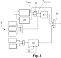
- FIG figure 3 shows a second embodiment of the invention in contrast to the previously described embodiment of FIG figure 2 , a limit value calculation with an upper limit value and a lower limit value takes place.
- the limit values are calculated as a function of the vehicle speed v in a limit value calculation unit 20.
- the basic engine torque T basic is limited to the calculated limit values.
- the limited basic engine torque T basic,limit is forwarded to the first limiter 13 so that it limits the signal of the first subgroup 8 to the limited basic engine torque T basic,limit .
- the output values of the first limiter 13 and the second limiter 18 and the originally calculated basic engine torque T basic then flow into the third adder 19 . It can thus be ensured that the resulting motor torque used to control the motor has the required safety level.
Description
Die vorliegende Erfindung betrifft ein Verfahren zur Steuerung eines Steer-by-Wire-Lenksystems mit den Merkmalen des Oberbegriffs des Anspruchs 1 und ein Steer-by-Wire-Lenksystem mit den Merkmalen des Oberbegriffs des Anspruchs 7.The present invention relates to a method for controlling a steer-by-wire steering system having the features of the preamble of
Bei Steer-by-Wire-Lenksystemen ist die Stellung der gelenkten Räder nicht direkt mit dem Lenkeingabemittel, beispielsweise einem Lenkrad, gekoppelt. Es besteht eine Verbindung zwischen dem Lenkrad und den gelenkten Rädern über elektrische Signale. Der Fahrerlenkwunsch wird von einem Lenkwinkelsensor abgegriffen, und in Abhängigkeit von dem Fahrerlenkwunsch wird über einen Lenksteller die Stellung der gelenkten Räder geregelt. Eine mechanische Verbindung zu den Rädern ist nicht vorgesehen, sodass nach Betätigung des Lenkrads keine unmittelbare Kraft-Rückmeldung an den Fahrer übermittelt wird. Allerdings ist eine entsprechend angepasste Rückmeldung, beispielsweise beim Parken oder bei einer Geradeausfahrt, bei der ein der Fahrzeugreaktion angepasstes, je nach Fahrzeughersteller unterschiedliches Lenkmoment als Kraft-Rückmeldung gewünscht ist, vorgesehen. Bei einer Kurvenfahrt wirken Reaktionskräfte als Querkräfte auf das Lenkgetriebe, welche der Feedback-Aktuator in Form eines der Lenkrichtung entgegengesetzten Moments nachbildet. Der Fahrer erfährt ein dadurch vorgebbares Lenkgefühl. Um bei Steer-by-Wire-Lenkungen die Rückwirkungen der Straße auf das Lenkrad zu simulieren, ist es notwendig, am Lenkrad oder der Lenksäule einen Feedback-Aktuator (FBA) vorzusehen, welcher in Abhängigkeit von den gewünschten Rückwirkungen der Lenkhandhabe ein Lenkgefühl aufprägt. Das Bereitstellen dieses Lenkgefühls ist sicherheitskritisch für eine zuverlässige und sichere Steuerung des Fahrzeuges.In steer-by-wire steering systems, the position of the steered wheels is not directly coupled to the steering input means, such as a steering wheel. There is a connection between the steering wheel and the steered wheels via electrical signals. The driver's steering request is picked up by a steering angle sensor, and depending on the driver's steering request, the position of the steered wheels is controlled via a steering actuator. A mechanical connection to the wheels is not provided, so that no immediate force feedback is transmitted to the driver after the steering wheel is actuated. However, a correspondingly adapted feedback is provided, for example when parking or when driving straight ahead, in which a steering torque adapted to the vehicle reaction and different depending on the vehicle manufacturer is desired as force feedback. When cornering, reaction forces act as transverse forces on the steering gear, which the feedback actuator simulates in the form of a torque in the opposite direction to the steering direction. The driver experiences a steering feel that can be predetermined as a result. In order to simulate the effects of the road on the steering wheel with steer-by-wire steering, it is necessary to provide a feedback actuator (FBA) on the steering wheel or the steering column, which impresses a steering feel depending on the desired reactions of the steering handle. Providing this steering feel is safety critical for reliable and safe control of the vehicle.
Aus
Es ist Aufgabe der vorliegenden Erfindung, ein verbessertes Verfahren zur sicheren Bereitstellung eines Lenkgefühls eines Feedback-Aktuators für eine Steer-by-Wire Lenkung eines Kraftfahrzeuges anzugeben.It is the object of the present invention to specify an improved method for reliably providing a steering feel of a feedback actuator for steer-by-wire steering of a motor vehicle.
Diese Aufgabe wird von einem Verfahren zur Steuerung eines Steer-by-Wire-Lenksystems für Kraftfahrzeuge mit den Merkmalen des Anspruchs 1 und einem Steer-by-Wire-Lenksystems für Kraftfahrzeuge mit den Merkmalen des Anspruchs 7 gelöst. In den Unteransprüchen sind vorteilhafte Weiterbildungen der Erfindung genannt.This object is achieved by a method for controlling a steer-by-wire steering system for motor vehicles having the features of
Demnach ist ein Verfahren zur Steuerung eines Steer-by-Wire-Lenksystems für Kraftfahrzeuge umfassend einen auf die gelenkten Räder wirkenden, in Abhängigkeit eines Fahrerlenkwunsches elektronisch geregelten Lenksteller, einen Rückwirkungen der Straße auf ein Lenkrad übertragenden Feedback-Aktuator, und eine Steuereinheit, die den Feedback-Aktuator steuert, vorgesehen, wobei das Verfahren folgende Verfahrensschritte zur Berechnung eines Motordrehmomentes umfasst:
- Bestimmen eines Basis-Motordrehmoments, welches fahrzeugzustands- und lageabhängig ist;
- Bereitstellen wenigstens einer Lenkfunktion, die Teil einer ersten Untergruppe von Lenkfunktionen ist;
- Begrenzen des Ausgangswertes der wenigstens einen Lenkfunktion zum Erreichen eines vorgegebenen Sicherheitsniveaus in einem ersten Begrenzer;
- Adaption des Basis-Motordrehmoments mittels des begrenzten Ausgangswert der wenigstens einen Lenkfunktion in einem Summierer;
- Ansteuern des Feedback-Aktuators mit dem von dem Summierer ausgegebenen resultierenden Motordrehmoment.
- determining a base engine torque which is dependent on vehicle condition and location;
- Providing at least one steering function that is part of a first subset of steering functions is;
- Limiting the initial value of the at least one steering function to achieve a predetermined safety level in a first limiter;
- Adaptation of the base engine torque by means of the limited output value of the at least one steering function in an adder;
- Driving the feedback actuator with the resulting motor torque output from the summer.
Durch dieses Verfahren kann auf eine Weise sichergestellt werden, dass die von der wenigstens einen Lenkfunktion berechneten Werte in einem sicheren Motordrehmoment bzw. Rückstellmoment resultieren. Unter "sicher" wird in diesem Fall verstanden, dass der Feedback-Aktuator nicht blockiert oder eine ungewünschte Bewegung der Lenkhandhabe im Rahmen einer Selbstlenkung vornimmt.This method can be used to ensure that the values calculated by the at least one steering function result in a safe motor torque or restoring torque. In this case, “safe” is understood to mean that the feedback actuator does not block or perform an undesired movement of the steering handle as part of self-steering.
Die wenigstens eine Lenkfunktion weist eine Lenkfunktion zum Bereitstellen einer Lenkungsdämpfung, einer Lenkungshysterese und/oder zum Rückstellen des Lenkrades zur Mitte auf. Diese Lenkfunktionen bilden ein Lenkgefühl einer konventionellen, elektromechanischen Lenkung ab.The at least one steering function has a steering function for providing steering damping, steering hysteresis and/or for returning the steering wheel to the center. These steering functions reflect the steering feel of a conventional, electromechanical steering system.
Der erste Begrenzer begrenzt den Ausgangswert der wenigstens einen Lenkfunktion in Abhängigkeit von wenigstens einem Parameter ausgewählt aus der Gruppe umfassend eine Fahrzeuggeschwindigkeit, eine Winkelgeschwindigkeit des Motors des Feedback-Aktuators, ein vom dem Fahrer aufgebrachtes Drehmoment am Lenkrad und ein Lenkradlenkwinkel. Dazu hat der Begrenzer vorzugsweise für jeden Wert des relevanten Parameters ein maximal zulässiges Motordrehmoment hinterlegt.The first limiter limits the output value of the at least one steering function depending on at least one parameter selected from the group comprising a vehicle speed, an angular velocity of the motor of the feedback actuator, a torque applied by the driver to the steering wheel and a steering wheel steering angle. For this purpose, the limiter has preferably stored a maximum permissible engine torque for each value of the relevant parameter.
Es kann aber auch vorgesehen sein, dass der Begrenzer den Ausgangswert der wenigstens einen Lenkfunktion auf ein begrenztes Basismotordrehmoment begrenzt, wobei das begrenzte Basismotordrehmoment durch Anwenden eines oberen Grenzwertes und eines unteren Grenzwertes auf das Basismotordrehmoment berechnet wird. Dabei wird bevorzugt der obere und untere Grenzwert in Abhängigkeit der Fahrzeuggeschwindigkeit berechnet.However, it can also be provided that the limiter limits the output value of the at least one steering function to a limited base engine torque, the limited base engine torque being calculated by applying an upper limit value and a lower limit value to the base engine torque. The upper and lower limit values are preferred calculated depending on the vehicle speed.
In dem Fall, dass wenigstens zwei Lenkfunktionen vorgesehen sind, deren Ausgangswerte nicht das benötigte Sicherheitsniveau aufweisen, werden diese in einem ersten Summierer verrechnet, bevor sie in dem ersten Begrenzer begrenzt werden.If at least two steering functions are provided, the output values of which do not have the required safety level, these are calculated in a first adder before they are limited in the first limiter.
Es kann weiterhin eine zweite Untergruppe an Lenkfunktionen mit wenigstens einer Lenkfunktion vorgesehen sein, deren Ausgangswert in den Summierer zur Adaption des Basis-Motordrehmoments einfließt. Sollte diese Lenkfunktion Ausgangswerte mit einem zu niedrigen Sicherheitsniveau ermitteln, kann ein weiterer Begrenzer vorgesehen sein.Furthermore, a second subgroup of steering functions can be provided with at least one steering function, the output value of which flows into the adder for adapting the base motor torque. Should this steering function determine output values with a safety level that is too low, a further limiter can be provided.
Die Aufgabe wird zudem von einem Steer-by-Wire-Lenksystem für Kraftfahrzeuge umfassend einen auf die gelenkten Räder wirkenden, in Abhängigkeit eines Fahrerlenkwunsches elektronisch geregelten Lenksteller, einen Rückwirkungen der Straße auf ein Lenkrad übertragenden Feedback-Aktuator, und eine Steuereinheit, die den Feedback-Aktuator steuert, gelöst, wobei die Steuereinheit dazu eingerichtet ist das zuvor beschriebene Verfahren auszuführen.The task is also performed by a steer-by-wire steering system for motor vehicles comprising a steering actuator that acts on the steered wheels and is electronically controlled as a function of a driver's steering request, a feedback actuator that transmits reactions from the road to a steering wheel, and a control unit that transmits the feedback -Actuator controls solved, wherein the control unit is set up to perform the method described above.
Zwei bevorzugte Ausführungsformen der Erfindung werden nachfolgend anhand der Zeichnungen näher erläutert. Gleichartige oder gleichwirkende Bauteile werden in den Figuren mit denselben Bezugszeichen bezeichnet. Es zeigen:
- Fig. 1:
- ein Blockdiagramm einer Steuerung eines Steer-by-Wire-Lenksystems,
- Fig. 2:
- ein Blockdiagramm einer erfindungsgemäßen Berechnung eines Motordrehmomentes zur Ansteuerung eines Feedback-Aktuators, sowie
- Fig. 3:
- ein Blockdiagramm einer zweiten erfindungsgemäßen Berechnung eines Motordrehmomentes zur Ansteuerung eines Feedback-Aktuators.
- Figure 1:
- a block diagram of a controller of a steer-by-wire steering system,
- Figure 2:
- a block diagram of an inventive calculation of a motor torque for controlling a feedback actuator, and
- Figure 3:
- a block diagram of a second inventive calculation of a motor torque for controlling a feedback actuator.
In der
Wie in
Es findet dabei eine Vielzahl an Lenkfunktionen Verwendung. Im Wesentlichen teilt sich die Berechnung des Motordrehmomentes TFBA in zwei Hauptteile auf. In einem ersten Teil 6 wird ein Basismotordrehmoment Tbasic anhand des Drehwinkels α und der Fahrzeuggeschwindigkeit v bestimmt. Es können bei der Berechnung weitere Größen, wie beispielsweise der Gierwinkel und die Querbeschleunigung des Fahrzeuges einfließen. Die dazu vorgesehene Basiskurve, die Lenkgeschwindigkeit und Fahrzeuggeschwindigkeit abhängig ist, liefert stets ein sicheres Basismotordrehmoment Tbasic was ein Basislenkgefühl am Lenkrad hervorruft.A large number of steering functions are used. Basically, the calculation of the engine torque T FBA is divided into two main parts. In a
In einem zweiten Teil 7 wird eine Vielzahl an Lenkfunktionen zur Adaption des Basislenkgefühls verwendet. Um dem Fahrer bei einer Steer-by-Wire-Lenkung das Gefühl einer konventionellen Lenkung zu vermitteln, ist in einer ersten Untergruppe 8 eine Lenkfunktion zum Bereitstellen einer Lenkungsdämpfung 9 vorgesehen, die heftige oder abrupte Lenkreaktionen und Lenkbewegungen dämpft. Zudem umfasst die erste Untergruppe 8 bevorzugt eine Lenkfunktion 10, die eine Lenkungshysterese (Lenkmoment-Lenkwinkel) bereitstellt, die die Lenkungsreibung bestimmt. Es können in der ersten Untergruppe 8 weitere Lenkfunktionen 11 vorgesehen sein, beispielsweise eine Funktion zum Rückstellen des Lenkrades zur Mitte und dergleichen. Die Ausgangswerte der Lenkfunktionen der ersten Untergruppe 8 werden einem ersten Summierer 12 zugeführt. Da die Ausgangswerte nicht das benötigte Sicherheitsniveau aufweisen, wird das Ausgangssignal des ersten Summierers 12 in einem ersten Begrenzer 13 zum Erreichen des benötigten Sicherheitsniveaus begrenzt. Der erste Begrenzer 13 kann dabei das Ausgangssignal des ersten Summierers 12 in Abhängigkeit von den folgenden Parametern begrenzen: der Fahrzeuggeschwindigkeit, der Winkelgeschwindigkeit des Motors, dem vom Fahrer aufgebrachten Drehmoment am Lenkrad und/oder dem Lenkradlenkwinkel. Hier dargestellt ist eine Begrenzung in Abhängigkeit der Fahrzeuggeschwindigkeit v. Der erste Begrenzer 13 stellt somit sicher, dass das von dem ersten Summierer 12 ausgegebene Motordrehmoment innerhalb eines zulässigen Bereichs ist und eine unkontrollierbare Motordrehmomentanfrage nicht an den Feedback-Aktuator weitergegeben wird. Dafür weist der erste Begrenzer 13 das maximal zulässige Motordrehmoment für die entsprechenden Werte der zuvor aufgelisteten Parameter auf. Es ist eine fahrzeuggeschwindigkeitsabhängige Motordrehmomentgrenze vorgesehen. Bei den Werten kann es sich um Messwerte oder Schätzwerte handeln, die das benötigte Sicherheitsniveau haben. Das maximal zulässige Motordrehmoment wird über das maximal zulässige Rückstellmoment des Feedback-Aktuators am Lenkrad definiert.In a
Es ist weiterhin eine zweite Untergruppe 14, die die Dämpfungsfunktionen und den Begrenzer enthält, mit Lenkfunktionen 15,16 vorgesehen, deren Ausgangswerte in einem zweiten Summierer 17 verrechnet werden und durch einen zweiten Begrenzer 18 begrenzt werden. Dieser zweite Begrenzer 18 nimmt eine Begrenzung in Abhängigkeit von der Fahrzeuggeschwindigkeit v und der Winkelgeschwindigkeit des Motors ω vor.There is also a
Ein dritter Summierer 19 verrechnet des Basismotordrehmomentes Tbasic mit dem ersten Ausgangsmotordrehmoment des ersten Begrenzers 13 und dem zweiten Ausgangsmotordrehmoment des zweiten Begrenzers 18. Es können auch noch weitere Lenkfunktionen vorgesehen sein, die bereits das benötigte Sicherheitsniveau erfüllen und ebenfalls in den dritten Summierer 19 einfließen. Das Ausgangssignal des dritten Summierers 19 ist das zu Ansteuerung des Feedback-Aktuators verwendete resultierende Motordrehmoment TFBA.A
Claims (7)
- A method for controlling a steer-by-wire steering system for motor vehicles, comprising a steering actuator (3) which acts on the steered wheels and is electronically controlled in accordance with a driver's steering request, a feedback actuator (2) which transmits reactions of the road to a steering wheel, and a control unit (5) which controls the feedback actuator (2), wherein the following method steps for calculating a motor torque (TFBA) for controlling the motor of the feedback actuator (2) are provided:• determining a basic motor torque (Tbasic) which is dependent on the driving state and on the position;• providing at least one steering function (9, 10, 11) which is part of a first subgroup of steering functions (8);• limiting the output value of the at least one steering function (9, 10, 11) to reach a predefined safety level in a first limiter (13);• adaptation of the basic motor torque (Tbasic) by means of the limited output value of the at least one steering function in a summing element (19) to obtain a resulting motor torque (TFBA);• actuating the feedback actuator (2) with the resulting motor torque (TFBA) which is output by the summing element (19),characterized in that the at least one steering function (9, 10, 11) has a steering function for providing a damping of the steering, a steering hysteresis and/or for resetting the steering wheel to the center, wherein the first limiter (13) limits the output value of the at least one steering function (9, 10, 11) in accordance with at least one parameter selected from the group comprising a vehicle speed (v), an angular speed (ω) of the motor of the feedback actuator, a torque, applied by the driver, at the steering wheel, and a steering wheel steering angle (α).
- The method as claimed in claim 1, characterized in that the first limiter (13) has a maximum permissible motor torque for each value of the relevant parameter.
- The method as claimed in claim 1, characterized in that the first limiter (13) limits the output value of the at least one steering function (9, 10, 11) to a limited basic motor torque (Tbasic,limit), wherein the limited basic motor torque (Tbasic,limit) is calculated by applying an upper limiting value and a lower limiting value to the basic motor torque (Tbasic).
- The method as claimed in claim 3, characterized in that the upper and lower limiting values are calculated as a function of the vehicle speed (v).
- The method as claimed in one of the preceding claims, characterized in that at least two steering functions (9, 10, 11) are provided, the output values of which are combined in a first summing element (12) before the output value of the first summing element (12) is limited in the first limiter (13).
- The method as claimed in one of the preceding claims, characterized in that a second subgroup of steering functions (14) is provided with at least one steering function (15, 16) whose output value is input into the summing element (19) for the adaptation of the basic motor torque (Tbasic) .
- A steer-by-wire steering system for motor vehicles, comprising a steering actuator (3) which acts on the steered wheels and is electronically controlled in accordance with a driver's steering request, a feedback actuator (2) which transmits reactions at the road to a steering wheel, and a control unit (5) which controls the feedback actuator (2), characterized in that the control unit (5) is configured to execute the method as claimed in one of the preceding claims 1 to 6.
Applications Claiming Priority (2)
| Application Number | Priority Date | Filing Date | Title |
|---|---|---|---|
| DE102018109084.6A DE102018109084A1 (en) | 2018-04-17 | 2018-04-17 | Method for controlling a steer-by-wire steering system with a limiter to achieve a safety level |
| PCT/EP2019/059509 WO2019201792A1 (en) | 2018-04-17 | 2019-04-12 | Method for controlling a steer-by-wire steering system comprising a limiter for reaching a safety level |
Publications (2)
| Publication Number | Publication Date |
|---|---|
| EP3781454A1 EP3781454A1 (en) | 2021-02-24 |
| EP3781454B1 true EP3781454B1 (en) | 2023-07-19 |
Family
ID=66349491
Family Applications (1)
| Application Number | Title | Priority Date | Filing Date |
|---|---|---|---|
| EP19720786.3A Active EP3781454B1 (en) | 2018-04-17 | 2019-04-12 | Method for controlling a steer-by-wire steering system comprising a limiter for reaching a safety level |
Country Status (5)
| Country | Link |
|---|---|
| US (1) | US11485405B2 (en) |
| EP (1) | EP3781454B1 (en) |
| CN (1) | CN111989250B (en) |
| DE (1) | DE102018109084A1 (en) |
| WO (1) | WO2019201792A1 (en) |
Families Citing this family (4)
| Publication number | Priority date | Publication date | Assignee | Title |
|---|---|---|---|---|
| DE102020209961A1 (en) | 2020-08-06 | 2022-02-10 | Zf Friedrichshafen Ag | Method for operating a steer-by-wire system in a motor vehicle and control device, computer program and steer-by-wire system |
| US11541862B2 (en) | 2020-08-27 | 2023-01-03 | Deere & Company | Operator selectable steering mode with variable torque feedback and system thereof |
| DE102020211657A1 (en) * | 2020-09-17 | 2022-03-17 | Ford Global Technologies, Llc | Steering system and method of operating a steering system |
| BE1030678B1 (en) * | 2022-06-29 | 2024-01-29 | Thyssenkrupp Presta Ag | Steer-by-wire steering system and method for operating a feedback actuator comprising an electric machine in a steering system of a motor vehicle |
Family Cites Families (12)
| Publication number | Priority date | Publication date | Assignee | Title |
|---|---|---|---|---|
| DE19912169A1 (en) * | 1998-12-29 | 2000-07-06 | Bosch Gmbh Robert | Steer-by-wire steering system for vehicles has electronic steering regulator connected to steering control devices that modifies driver's steering demand depending on dynamic parameters |
| JP3593110B2 (en) * | 2002-02-14 | 2004-11-24 | 三菱電機株式会社 | Vehicle steering system |
| JP2004009857A (en) | 2002-06-05 | 2004-01-15 | Mitsubishi Motors Corp | Steering control device for vehicle |
| US8116943B2 (en) * | 2008-04-24 | 2012-02-14 | GM Global Technology Operations LLC | Method and apparatus for minimizing driver disturbance in a limited by-wire active steering system |
| DE102009000868B4 (en) * | 2009-02-16 | 2011-12-29 | Ford Global Technologies, Llc | Device and method for controlling a steering system in a vehicle |
| JP5131324B2 (en) * | 2010-07-09 | 2013-01-30 | トヨタ自動車株式会社 | Vehicle steering system |
| WO2014054474A1 (en) * | 2012-10-01 | 2014-04-10 | 日産自動車株式会社 | Stability control device |
| MX2015004135A (en) | 2012-10-04 | 2015-07-06 | Nissan Motor | Steering control device. |
| JP5994861B2 (en) * | 2012-10-04 | 2016-09-21 | 日産自動車株式会社 | Steering control device |
| DE102013218721B4 (en) * | 2012-10-16 | 2017-11-16 | Ford Global Technologies, Llc | Method for reducing steering torque of a steering of a motor vehicle |
| DE102014216574B4 (en) * | 2014-08-21 | 2017-12-21 | Ford Global Technologies, Llc | Limitation of torque requirements of steering assistance equipment |
| KR102419260B1 (en) * | 2016-07-12 | 2022-07-12 | 현대모비스 주식회사 | Apparatus for controlling steering in steer-by-wire system and method thereof |
-
2018
- 2018-04-17 DE DE102018109084.6A patent/DE102018109084A1/en active Pending
-
2019
- 2019-04-12 WO PCT/EP2019/059509 patent/WO2019201792A1/en unknown
- 2019-04-12 EP EP19720786.3A patent/EP3781454B1/en active Active
- 2019-04-12 CN CN201980026092.1A patent/CN111989250B/en active Active
- 2019-04-12 US US17/040,097 patent/US11485405B2/en active Active
Also Published As
| Publication number | Publication date |
|---|---|
| DE102018109084A1 (en) | 2019-10-17 |
| CN111989250B (en) | 2022-12-06 |
| WO2019201792A1 (en) | 2019-10-24 |
| EP3781454A1 (en) | 2021-02-24 |
| US11485405B2 (en) | 2022-11-01 |
| CN111989250A (en) | 2020-11-24 |
| US20210024123A1 (en) | 2021-01-28 |
Similar Documents
| Publication | Publication Date | Title |
|---|---|---|
| EP3496995B1 (en) | Controlling a steer-by-wire steering system | |
| EP3781454B1 (en) | Method for controlling a steer-by-wire steering system comprising a limiter for reaching a safety level | |
| EP3717332B1 (en) | Method for controlling a steer-by-wire steering system with an active return function | |
| EP2393701B1 (en) | Determining a target steering torque in a steering device | |
| EP3595958B1 (en) | Estimating the rack force in a steer-by-wire system | |
| EP1849682B1 (en) | Method for controlling steering | |
| EP3740416B1 (en) | Method for controlling a steer-by-wire steering system when a maximum available power of the steering adjuster is reached | |
| WO2011038865A1 (en) | Control method for electric servo steering systems | |
| DE10248343A1 (en) | Control process for motor vehicle steer by wire system, adjusts operating force simulator on basis of driving and road wheel parameters | |
| DE10141425A1 (en) | Method for generating driving-related additional torque on a motor vehicle's steering wheel, forms extra torque using a factor and a floating angle to set a steering wheel position in advance to match steerable wheel positions. | |
| DE102018130664B4 (en) | NOTIFICATION OF RACK LIMITATION CONDITIONS FOR STEER-BY-WIRE STEERING SYSTEMS | |
| EP3227164A1 (en) | Steering device and method for controlling a steering device | |
| DE102019214446A1 (en) | Method and device for simultaneous lateral vehicle guidance by the driver and assistance system with electric steering actuators | |
| WO2012065961A1 (en) | Method for operating a power steering mechanism | |
| EP3481703B1 (en) | Steer-by-wire steering system having different damping as a turn is entered and exited | |
| DE102020213553B4 (en) | Steering system and method of operating a steering system | |
| EP3727998A1 (en) | Method for operating a steer-by-wire steering system for a motor vehicle, and steering system for a motor vehicle | |
| EP3833593B1 (en) | Steering-rack-force optimised steering sensation of a steer-by-wire motor vehicle steering system | |
| DE102019134568A1 (en) | Method for operating a power steering system of a vehicle, power steering system and vehicle | |
| EP1377493B1 (en) | Electronic end stop for a power steering unit | |
| DE102018202483A1 (en) | Method for operating a steering system and steering system | |
| EP3980314B1 (en) | Setting a vehicle steering angle with a vehicle steering system while taking into consideration dynamic variables | |
| DE102008056472A1 (en) | Servo steering system i.e. electromechanical servo steering system, for motor vehicle, has superimposing device superimposing target moment signal on compensation signal, and drive unit controlled based on corrected moment signal |
Legal Events
| Date | Code | Title | Description |
|---|---|---|---|
| STAA | Information on the status of an ep patent application or granted ep patent |
Free format text: STATUS: UNKNOWN |
|
| STAA | Information on the status of an ep patent application or granted ep patent |
Free format text: STATUS: THE INTERNATIONAL PUBLICATION HAS BEEN MADE |
|
| PUAI | Public reference made under article 153(3) epc to a published international application that has entered the european phase |
Free format text: ORIGINAL CODE: 0009012 |
|
| STAA | Information on the status of an ep patent application or granted ep patent |
Free format text: STATUS: REQUEST FOR EXAMINATION WAS MADE |
|
| 17P | Request for examination filed |
Effective date: 20201117 |
|
| AK | Designated contracting states |
Kind code of ref document: A1 Designated state(s): AL AT BE BG CH CY CZ DE DK EE ES FI FR GB GR HR HU IE IS IT LI LT LU LV MC MK MT NL NO PL PT RO RS SE SI SK SM TR |
|
| AX | Request for extension of the european patent |
Extension state: BA ME |
|
| RAP1 | Party data changed (applicant data changed or rights of an application transferred) |
Owner name: THYSSENKRUPP PRESTA AG Owner name: THYSSENKRUPP AG |
|
| DAV | Request for validation of the european patent (deleted) | ||
| DAX | Request for extension of the european patent (deleted) | ||
| GRAP | Despatch of communication of intention to grant a patent |
Free format text: ORIGINAL CODE: EPIDOSNIGR1 |
|
| STAA | Information on the status of an ep patent application or granted ep patent |
Free format text: STATUS: GRANT OF PATENT IS INTENDED |
|
| INTG | Intention to grant announced |
Effective date: 20230320 |
|
| GRAS | Grant fee paid |
Free format text: ORIGINAL CODE: EPIDOSNIGR3 |
|
| GRAA | (expected) grant |
Free format text: ORIGINAL CODE: 0009210 |
|
| STAA | Information on the status of an ep patent application or granted ep patent |
Free format text: STATUS: THE PATENT HAS BEEN GRANTED |
|
| AK | Designated contracting states |
Kind code of ref document: B1 Designated state(s): AL AT BE BG CH CY CZ DE DK EE ES FI FR GB GR HR HU IE IS IT LI LT LU LV MC MK MT NL NO PL PT RO RS SE SI SK SM TR |
|
| REG | Reference to a national code |
Ref country code: GB Ref legal event code: FG4D Free format text: NOT ENGLISH |
|
| REG | Reference to a national code |
Ref country code: CH Ref legal event code: EP |
|
| REG | Reference to a national code |
Ref country code: DE Ref legal event code: R096 Ref document number: 502019008584 Country of ref document: DE |
|
| REG | Reference to a national code |
Ref country code: IE Ref legal event code: FG4D Free format text: LANGUAGE OF EP DOCUMENT: GERMAN |
|
| REG | Reference to a national code |
Ref country code: DE Ref legal event code: R084 Ref document number: 502019008584 Country of ref document: DE |
|
| REG | Reference to a national code |
Ref country code: LT Ref legal event code: MG9D |
|
| REG | Reference to a national code |
Ref country code: NL Ref legal event code: MP Effective date: 20230719 |
|
| PG25 | Lapsed in a contracting state [announced via postgrant information from national office to epo] |
Ref country code: NL Free format text: LAPSE BECAUSE OF FAILURE TO SUBMIT A TRANSLATION OF THE DESCRIPTION OR TO PAY THE FEE WITHIN THE PRESCRIBED TIME-LIMIT Effective date: 20230719 |
|
| PG25 | Lapsed in a contracting state [announced via postgrant information from national office to epo] |
Ref country code: GR Free format text: LAPSE BECAUSE OF FAILURE TO SUBMIT A TRANSLATION OF THE DESCRIPTION OR TO PAY THE FEE WITHIN THE PRESCRIBED TIME-LIMIT Effective date: 20231020 |
|
| PG25 | Lapsed in a contracting state [announced via postgrant information from national office to epo] |
Ref country code: IS Free format text: LAPSE BECAUSE OF FAILURE TO SUBMIT A TRANSLATION OF THE DESCRIPTION OR TO PAY THE FEE WITHIN THE PRESCRIBED TIME-LIMIT Effective date: 20231119 |
|
| PG25 | Lapsed in a contracting state [announced via postgrant information from national office to epo] |
Ref country code: SE Free format text: LAPSE BECAUSE OF FAILURE TO SUBMIT A TRANSLATION OF THE DESCRIPTION OR TO PAY THE FEE WITHIN THE PRESCRIBED TIME-LIMIT Effective date: 20230719 Ref country code: RS Free format text: LAPSE BECAUSE OF FAILURE TO SUBMIT A TRANSLATION OF THE DESCRIPTION OR TO PAY THE FEE WITHIN THE PRESCRIBED TIME-LIMIT Effective date: 20230719 Ref country code: PT Free format text: LAPSE BECAUSE OF FAILURE TO SUBMIT A TRANSLATION OF THE DESCRIPTION OR TO PAY THE FEE WITHIN THE PRESCRIBED TIME-LIMIT Effective date: 20231120 Ref country code: NO Free format text: LAPSE BECAUSE OF FAILURE TO SUBMIT A TRANSLATION OF THE DESCRIPTION OR TO PAY THE FEE WITHIN THE PRESCRIBED TIME-LIMIT Effective date: 20231019 Ref country code: LV Free format text: LAPSE BECAUSE OF FAILURE TO SUBMIT A TRANSLATION OF THE DESCRIPTION OR TO PAY THE FEE WITHIN THE PRESCRIBED TIME-LIMIT Effective date: 20230719 Ref country code: LT Free format text: LAPSE BECAUSE OF FAILURE TO SUBMIT A TRANSLATION OF THE DESCRIPTION OR TO PAY THE FEE WITHIN THE PRESCRIBED TIME-LIMIT Effective date: 20230719 Ref country code: IS Free format text: LAPSE BECAUSE OF FAILURE TO SUBMIT A TRANSLATION OF THE DESCRIPTION OR TO PAY THE FEE WITHIN THE PRESCRIBED TIME-LIMIT Effective date: 20231119 Ref country code: HR Free format text: LAPSE BECAUSE OF FAILURE TO SUBMIT A TRANSLATION OF THE DESCRIPTION OR TO PAY THE FEE WITHIN THE PRESCRIBED TIME-LIMIT Effective date: 20230719 Ref country code: GR Free format text: LAPSE BECAUSE OF FAILURE TO SUBMIT A TRANSLATION OF THE DESCRIPTION OR TO PAY THE FEE WITHIN THE PRESCRIBED TIME-LIMIT Effective date: 20231020 Ref country code: FI Free format text: LAPSE BECAUSE OF FAILURE TO SUBMIT A TRANSLATION OF THE DESCRIPTION OR TO PAY THE FEE WITHIN THE PRESCRIBED TIME-LIMIT Effective date: 20230719 |
|
| PG25 | Lapsed in a contracting state [announced via postgrant information from national office to epo] |
Ref country code: PL Free format text: LAPSE BECAUSE OF FAILURE TO SUBMIT A TRANSLATION OF THE DESCRIPTION OR TO PAY THE FEE WITHIN THE PRESCRIBED TIME-LIMIT Effective date: 20230719 |