EP3781421B1 - Exchanger element for a vehicle and vehicle equipped with such an exchanger element - Google Patents
Exchanger element for a vehicle and vehicle equipped with such an exchanger element Download PDFInfo
- Publication number
- EP3781421B1 EP3781421B1 EP19727060.6A EP19727060A EP3781421B1 EP 3781421 B1 EP3781421 B1 EP 3781421B1 EP 19727060 A EP19727060 A EP 19727060A EP 3781421 B1 EP3781421 B1 EP 3781421B1
- Authority
- EP
- European Patent Office
- Prior art keywords
- exchanger element
- installation space
- packing
- vehicle
- flow path
- Prior art date
- Legal status (The legal status is an assumption and is not a legal conclusion. Google has not performed a legal analysis and makes no representation as to the accuracy of the status listed.)
- Active
Links
- 238000009434 installation Methods 0.000 claims description 82
- 238000012856 packing Methods 0.000 claims description 71
- 239000004566 building material Substances 0.000 claims description 43
- 239000000463 material Substances 0.000 claims description 36
- 239000002861 polymer material Substances 0.000 claims description 23
- 238000004519 manufacturing process Methods 0.000 claims description 14
- 238000011144 upstream manufacturing Methods 0.000 claims description 13
- 238000000034 method Methods 0.000 claims description 12
- 239000012530 fluid Substances 0.000 claims description 10
- 239000007788 liquid Substances 0.000 claims description 7
- 235000011837 pasties Nutrition 0.000 claims description 7
- 238000005192 partition Methods 0.000 claims description 6
- XLYOFNOQVPJJNP-UHFFFAOYSA-N water Chemical compound O XLYOFNOQVPJJNP-UHFFFAOYSA-N 0.000 claims description 6
- 238000005187 foaming Methods 0.000 claims description 5
- 230000009969 flowable effect Effects 0.000 claims description 4
- 239000012768 molten material Substances 0.000 claims description 4
- 239000003795 chemical substances by application Substances 0.000 claims description 3
- 230000000295 complement effect Effects 0.000 claims description 3
- 239000012784 inorganic fiber Substances 0.000 claims description 3
- 238000005485 electric heating Methods 0.000 claims description 2
- 239000002657 fibrous material Substances 0.000 claims description 2
- 239000002245 particle Substances 0.000 description 9
- -1 polypropylene Polymers 0.000 description 8
- PPBRXRYQALVLMV-UHFFFAOYSA-N Styrene Chemical compound C=CC1=CC=CC=C1 PPBRXRYQALVLMV-UHFFFAOYSA-N 0.000 description 6
- 238000009413 insulation Methods 0.000 description 6
- JVTAAEKCZFNVCJ-UHFFFAOYSA-N lactic acid Chemical compound CC(O)C(O)=O JVTAAEKCZFNVCJ-UHFFFAOYSA-N 0.000 description 6
- 239000004743 Polypropylene Substances 0.000 description 5
- 238000002485 combustion reaction Methods 0.000 description 5
- 238000001746 injection moulding Methods 0.000 description 5
- 229920001155 polypropylene Polymers 0.000 description 5
- CURLTUGMZLYLDI-UHFFFAOYSA-N Carbon dioxide Chemical compound O=C=O CURLTUGMZLYLDI-UHFFFAOYSA-N 0.000 description 4
- 239000007789 gas Substances 0.000 description 4
- 238000010438 heat treatment Methods 0.000 description 4
- VGGSQFUCUMXWEO-UHFFFAOYSA-N Ethene Chemical compound C=C VGGSQFUCUMXWEO-UHFFFAOYSA-N 0.000 description 3
- 239000005977 Ethylene Substances 0.000 description 3
- 239000004698 Polyethylene Substances 0.000 description 3
- 238000004378 air conditioning Methods 0.000 description 3
- 238000010276 construction Methods 0.000 description 3
- 229920001577 copolymer Polymers 0.000 description 3
- 239000000835 fiber Substances 0.000 description 3
- 239000006260 foam Substances 0.000 description 3
- 229920001519 homopolymer Polymers 0.000 description 3
- 239000004310 lactic acid Substances 0.000 description 3
- 235000014655 lactic acid Nutrition 0.000 description 3
- 239000000203 mixture Substances 0.000 description 3
- 229920000747 poly(lactic acid) Polymers 0.000 description 3
- 229920000573 polyethylene Polymers 0.000 description 3
- 229920000642 polymer Polymers 0.000 description 3
- 229920002635 polyurethane Polymers 0.000 description 3
- 239000004814 polyurethane Substances 0.000 description 3
- QQONPFPTGQHPMA-UHFFFAOYSA-N propylene Natural products CC=C QQONPFPTGQHPMA-UHFFFAOYSA-N 0.000 description 3
- 125000004805 propylene group Chemical group [H]C([H])([H])C([H])([*:1])C([H])([H])[*:2] 0.000 description 3
- 238000000110 selective laser sintering Methods 0.000 description 3
- 239000000126 substance Substances 0.000 description 3
- 238000012546 transfer Methods 0.000 description 3
- 238000010146 3D printing Methods 0.000 description 2
- IJGRMHOSHXDMSA-UHFFFAOYSA-N Atomic nitrogen Chemical compound N#N IJGRMHOSHXDMSA-UHFFFAOYSA-N 0.000 description 2
- 229930040373 Paraformaldehyde Natural products 0.000 description 2
- 239000004793 Polystyrene Substances 0.000 description 2
- 238000010521 absorption reaction Methods 0.000 description 2
- 239000000654 additive Substances 0.000 description 2
- 230000000996 additive effect Effects 0.000 description 2
- 230000015572 biosynthetic process Effects 0.000 description 2
- 239000001569 carbon dioxide Substances 0.000 description 2
- 229910002092 carbon dioxide Inorganic materials 0.000 description 2
- 238000004891 communication Methods 0.000 description 2
- 238000005755 formation reaction Methods 0.000 description 2
- 239000000446 fuel Substances 0.000 description 2
- 239000012528 membrane Substances 0.000 description 2
- 229920001707 polybutylene terephthalate Polymers 0.000 description 2
- 229920000139 polyethylene terephthalate Polymers 0.000 description 2
- 239000005020 polyethylene terephthalate Substances 0.000 description 2
- 229920005597 polymer membrane Polymers 0.000 description 2
- 229920006324 polyoxymethylene Polymers 0.000 description 2
- 239000011148 porous material Substances 0.000 description 2
- 230000005855 radiation Effects 0.000 description 2
- 230000035939 shock Effects 0.000 description 2
- 239000007787 solid Substances 0.000 description 2
- 229920001169 thermoplastic Polymers 0.000 description 2
- 239000004416 thermosoftening plastic Substances 0.000 description 2
- 230000001960 triggered effect Effects 0.000 description 2
- 239000012855 volatile organic compound Substances 0.000 description 2
- NIXOWILDQLNWCW-UHFFFAOYSA-M Acrylate Chemical compound [O-]C(=O)C=C NIXOWILDQLNWCW-UHFFFAOYSA-M 0.000 description 1
- 235000017166 Bambusa arundinacea Nutrition 0.000 description 1
- 235000017491 Bambusa tulda Nutrition 0.000 description 1
- 244000025254 Cannabis sativa Species 0.000 description 1
- 235000012766 Cannabis sativa ssp. sativa var. sativa Nutrition 0.000 description 1
- 235000012765 Cannabis sativa ssp. sativa var. spontanea Nutrition 0.000 description 1
- 229920000049 Carbon (fiber) Polymers 0.000 description 1
- UGFAIRIUMAVXCW-UHFFFAOYSA-N Carbon monoxide Chemical compound [O+]#[C-] UGFAIRIUMAVXCW-UHFFFAOYSA-N 0.000 description 1
- 229920002292 Nylon 6 Polymers 0.000 description 1
- 229920002302 Nylon 6,6 Polymers 0.000 description 1
- 244000082204 Phyllostachys viridis Species 0.000 description 1
- 235000015334 Phyllostachys viridis Nutrition 0.000 description 1
- 229920005830 Polyurethane Foam Polymers 0.000 description 1
- 239000004676 acrylonitrile butadiene styrene Substances 0.000 description 1
- 229920001893 acrylonitrile styrene Polymers 0.000 description 1
- QVGXLLKOCUKJST-UHFFFAOYSA-N atomic oxygen Chemical compound [O] QVGXLLKOCUKJST-UHFFFAOYSA-N 0.000 description 1
- 239000011425 bamboo Substances 0.000 description 1
- 239000011324 bead Substances 0.000 description 1
- 235000009120 camo Nutrition 0.000 description 1
- 239000004917 carbon fiber Substances 0.000 description 1
- 229910002091 carbon monoxide Inorganic materials 0.000 description 1
- 239000012876 carrier material Substances 0.000 description 1
- 235000005607 chanvre indien Nutrition 0.000 description 1
- 230000003750 conditioning effect Effects 0.000 description 1
- 238000001816 cooling Methods 0.000 description 1
- 238000013016 damping Methods 0.000 description 1
- 238000013461 design Methods 0.000 description 1
- 238000001035 drying Methods 0.000 description 1
- 239000013536 elastomeric material Substances 0.000 description 1
- 238000005516 engineering process Methods 0.000 description 1
- 239000004794 expanded polystyrene Substances 0.000 description 1
- 239000000945 filler Substances 0.000 description 1
- 239000011521 glass Substances 0.000 description 1
- 239000003365 glass fiber Substances 0.000 description 1
- 239000011487 hemp Substances 0.000 description 1
- 229910052500 inorganic mineral Inorganic materials 0.000 description 1
- 230000010354 integration Effects 0.000 description 1
- 150000002605 large molecules Chemical class 0.000 description 1
- 229920002521 macromolecule Polymers 0.000 description 1
- 238000013017 mechanical damping Methods 0.000 description 1
- 239000000155 melt Substances 0.000 description 1
- 239000011707 mineral Substances 0.000 description 1
- 229910052757 nitrogen Inorganic materials 0.000 description 1
- 229910052756 noble gas Inorganic materials 0.000 description 1
- 150000002835 noble gases Chemical class 0.000 description 1
- 229910052760 oxygen Inorganic materials 0.000 description 1
- 239000001301 oxygen Substances 0.000 description 1
- 229920000515 polycarbonate Polymers 0.000 description 1
- 239000004417 polycarbonate Substances 0.000 description 1
- 229920001296 polysiloxane Polymers 0.000 description 1
- 239000011496 polyurethane foam Substances 0.000 description 1
- SCUZVMOVTVSBLE-UHFFFAOYSA-N prop-2-enenitrile;styrene Chemical compound C=CC#N.C=CC1=CC=CC=C1 SCUZVMOVTVSBLE-UHFFFAOYSA-N 0.000 description 1
- 238000000926 separation method Methods 0.000 description 1
- 239000000454 talc Substances 0.000 description 1
- 229910052623 talc Inorganic materials 0.000 description 1
- 239000012815 thermoplastic material Substances 0.000 description 1
- 239000002918 waste heat Substances 0.000 description 1
Images

Classifications
-
- F—MECHANICAL ENGINEERING; LIGHTING; HEATING; WEAPONS; BLASTING
- F24—HEATING; RANGES; VENTILATING
- F24F—AIR-CONDITIONING; AIR-HUMIDIFICATION; VENTILATION; USE OF AIR CURRENTS FOR SCREENING
- F24F12/00—Use of energy recovery systems in air conditioning, ventilation or screening
- F24F12/001—Use of energy recovery systems in air conditioning, ventilation or screening with heat-exchange between supplied and exhausted air
- F24F12/006—Use of energy recovery systems in air conditioning, ventilation or screening with heat-exchange between supplied and exhausted air using an air-to-air heat exchanger
-
- B—PERFORMING OPERATIONS; TRANSPORTING
- B60—VEHICLES IN GENERAL
- B60H—ARRANGEMENTS OF HEATING, COOLING, VENTILATING OR OTHER AIR-TREATING DEVICES SPECIALLY ADAPTED FOR PASSENGER OR GOODS SPACES OF VEHICLES
- B60H1/00—Heating, cooling or ventilating [HVAC] devices
- B60H1/02—Heating, cooling or ventilating [HVAC] devices the heat being derived from the propulsion plant
- B60H1/03—Heating, cooling or ventilating [HVAC] devices the heat being derived from the propulsion plant and from a source other than the propulsion plant
- B60H1/039—Heating, cooling or ventilating [HVAC] devices the heat being derived from the propulsion plant and from a source other than the propulsion plant from air leaving the interior of the vehicle, i.e. heat recovery
-
- B—PERFORMING OPERATIONS; TRANSPORTING
- B60—VEHICLES IN GENERAL
- B60H—ARRANGEMENTS OF HEATING, COOLING, VENTILATING OR OTHER AIR-TREATING DEVICES SPECIALLY ADAPTED FOR PASSENGER OR GOODS SPACES OF VEHICLES
- B60H1/00—Heating, cooling or ventilating [HVAC] devices
- B60H1/00507—Details, e.g. mounting arrangements, desaeration devices
- B60H1/00514—Details of air conditioning housings
-
- B—PERFORMING OPERATIONS; TRANSPORTING
- B60—VEHICLES IN GENERAL
- B60H—ARRANGEMENTS OF HEATING, COOLING, VENTILATING OR OTHER AIR-TREATING DEVICES SPECIALLY ADAPTED FOR PASSENGER OR GOODS SPACES OF VEHICLES
- B60H1/00—Heating, cooling or ventilating [HVAC] devices
- B60H1/00007—Combined heating, ventilating, or cooling devices
- B60H1/00207—Combined heating, ventilating, or cooling devices characterised by the position of the HVAC devices with respect to the passenger compartment
-
- B—PERFORMING OPERATIONS; TRANSPORTING
- B60—VEHICLES IN GENERAL
- B60H—ARRANGEMENTS OF HEATING, COOLING, VENTILATING OR OTHER AIR-TREATING DEVICES SPECIALLY ADAPTED FOR PASSENGER OR GOODS SPACES OF VEHICLES
- B60H3/00—Other air-treating devices
- B60H3/06—Filtering
-
- F—MECHANICAL ENGINEERING; LIGHTING; HEATING; WEAPONS; BLASTING
- F28—HEAT EXCHANGE IN GENERAL
- F28D—HEAT-EXCHANGE APPARATUS, NOT PROVIDED FOR IN ANOTHER SUBCLASS, IN WHICH THE HEAT-EXCHANGE MEDIA DO NOT COME INTO DIRECT CONTACT
- F28D21/00—Heat-exchange apparatus not covered by any of the groups F28D1/00 - F28D20/00
- F28D21/0001—Recuperative heat exchangers
- F28D21/0003—Recuperative heat exchangers the heat being recuperated from exhaust gases
-
- F—MECHANICAL ENGINEERING; LIGHTING; HEATING; WEAPONS; BLASTING
- F28—HEAT EXCHANGE IN GENERAL
- F28D—HEAT-EXCHANGE APPARATUS, NOT PROVIDED FOR IN ANOTHER SUBCLASS, IN WHICH THE HEAT-EXCHANGE MEDIA DO NOT COME INTO DIRECT CONTACT
- F28D21/00—Heat-exchange apparatus not covered by any of the groups F28D1/00 - F28D20/00
- F28D21/0001—Recuperative heat exchangers
- F28D21/0014—Recuperative heat exchangers the heat being recuperated from waste air or from vapors
-
- F—MECHANICAL ENGINEERING; LIGHTING; HEATING; WEAPONS; BLASTING
- F28—HEAT EXCHANGE IN GENERAL
- F28D—HEAT-EXCHANGE APPARATUS, NOT PROVIDED FOR IN ANOTHER SUBCLASS, IN WHICH THE HEAT-EXCHANGE MEDIA DO NOT COME INTO DIRECT CONTACT
- F28D21/00—Heat-exchange apparatus not covered by any of the groups F28D1/00 - F28D20/00
- F28D21/0015—Heat and mass exchangers, e.g. with permeable walls
-
- F—MECHANICAL ENGINEERING; LIGHTING; HEATING; WEAPONS; BLASTING
- F24—HEATING; RANGES; VENTILATING
- F24F—AIR-CONDITIONING; AIR-HUMIDIFICATION; VENTILATION; USE OF AIR CURRENTS FOR SCREENING
- F24F1/00—Room units for air-conditioning, e.g. separate or self-contained units or units receiving primary air from a central station
- F24F1/02—Self-contained room units for air-conditioning, i.e. with all apparatus for treatment installed in a common casing
- F24F1/0373—Self-contained room units for air-conditioning, i.e. with all apparatus for treatment installed in a common casing characterised by heating arrangements
- F24F1/0375—Self-contained room units for air-conditioning, i.e. with all apparatus for treatment installed in a common casing characterised by heating arrangements with additional radiant heat-discharging elements, e.g. electric heaters
-
- Y—GENERAL TAGGING OF NEW TECHNOLOGICAL DEVELOPMENTS; GENERAL TAGGING OF CROSS-SECTIONAL TECHNOLOGIES SPANNING OVER SEVERAL SECTIONS OF THE IPC; TECHNICAL SUBJECTS COVERED BY FORMER USPC CROSS-REFERENCE ART COLLECTIONS [XRACs] AND DIGESTS
- Y02—TECHNOLOGIES OR APPLICATIONS FOR MITIGATION OR ADAPTATION AGAINST CLIMATE CHANGE
- Y02B—CLIMATE CHANGE MITIGATION TECHNOLOGIES RELATED TO BUILDINGS, e.g. HOUSING, HOUSE APPLIANCES OR RELATED END-USER APPLICATIONS
- Y02B30/00—Energy efficient heating, ventilation or air conditioning [HVAC]
- Y02B30/56—Heat recovery units
-
- Y—GENERAL TAGGING OF NEW TECHNOLOGICAL DEVELOPMENTS; GENERAL TAGGING OF CROSS-SECTIONAL TECHNOLOGIES SPANNING OVER SEVERAL SECTIONS OF THE IPC; TECHNICAL SUBJECTS COVERED BY FORMER USPC CROSS-REFERENCE ART COLLECTIONS [XRACs] AND DIGESTS
- Y02—TECHNOLOGIES OR APPLICATIONS FOR MITIGATION OR ADAPTATION AGAINST CLIMATE CHANGE
- Y02T—CLIMATE CHANGE MITIGATION TECHNOLOGIES RELATED TO TRANSPORTATION
- Y02T50/00—Aeronautics or air transport
- Y02T50/40—Weight reduction
Definitions
- the invention relates to a vehicle equipped with an exchanger element.
- the invention also relates to a method for producing an exchanger element pack for arrangement in an installation space on board a vehicle, in particular in a installation space assigned to a passenger cabin and/or an engine compartment, between the inner walls of the installation space and an exchanger element to be installed in the installation space.
- the use of a heat exchanger for heating passenger cabins is known.
- the waste heat from an internal combustion engine is used to preheat the supply air introduced into the passenger cabin using a heat exchanger. This use relies on the heat energy that occurs when the fuel is burned in the internal combustion engine.
- the WO 2005/036083 A1 discloses a heat exchanger for a fan.
- the invention is based on the object of enabling the heating or air conditioning of a vehicle area, in particular a passenger cabin and/or an engine compartment, with as little or no additional energy expenditure as possible.
- the invention provides a vehicle to which an exchanger element and a packing (4) are assigned, the exchanger element having an exhaust air flow path and a supply air flow path, and wherein the exhaust air flow path and the supply air flow path are separated from one another by partition wall sections which have heat-transferring wall areas, the exhaust air flow path providing a fluid connection from the interior of the vehicle, in particular from the passenger cabin or from Engine compartment, to the external environment of the vehicle, and wherein the supply air flow path forms a fluid connection from the external environment of the vehicle to a location on board the vehicle, in particular to the interior of the passenger cabin and / or the engine compartment, characterized in that the exchanger element in the pack is embedded, the external surface shape of which is complementary to the internal dimensions of an installation space on board the vehicle, in particular in the passenger cabin and / or in the engine compartment, for the installation of the exchanger element.
- the exchanger element according to the invention makes it possible to transfer part of the thermal energy of the exhaust air leaving the vehicle to the supply air entering the vehicle. This makes it possible to keep the passenger cabin warm for longer in winter, for example if there is no internal combustion engine (pure electric drive) or the internal combustion engine is not always switched on (hybrid drive).
- the packing therefore serves as an interface between the installation space and the exchanger element.
- the pack is a lining of at least a portion of the passenger cabin or the engine compartment with recesses for the exchanger element.
- the pack or part thereof serves to define air flows outside the exchanger element, which flow towards or away from the exchanger element.
- the packing also provides thermal insulation and sound insulation.
- the pack contains an expanded and/or foamed polymer material and/or a fiber material, in particular made of organic or inorganic fibers. It is particularly advantageous if the pack is made entirely of an expanded and/or foamed polymer material. This makes it possible to achieve good thermal insulation and sound insulation for the exchanger element with a low mass.
- a material with closed pores in particular a foamed polymer material, and / or a material with open pores, in particular an organic one or inorganic fiber material can be used.
- An expanded homopolymer such as expanded polypropylene (EPP), expanded polystyrene (EPS), expanded polyethylene (EPE) or expanded polylactide (EPLA) can be used as the expanded polymer material.
- EPP expanded polypropylene
- EPS expanded polystyrene
- EPE expanded polyethylene
- EPLA expanded polylactide
- an expanded copolymer can be used as the expanded polymer material, which has at least one of the components propylene, styrene, ethylene or lactic acid as a component.
- a mixture of expanded homopolymer can be used as the expanded polymer material, which has at least one of the components polypropylene (PP), polystyrene (PS), polyethylene (PE) or polylactide (PLA) as a component.
- PP polypropylene
- PS polystyrene
- PE polyethylene
- PLA polylactide
- a mixture of expanded copolymer can be used as the expanded polymer material, which has at least one of the components propylene, styrene, ethylene or lactic acid as a component.
- a mixture of expanded homopolymer and copolymer can be used as the expanded polymer material at least one of the components propylene, styrene, ethylene or lactic acid as a component.
- the expanded polymer material may have a density of 20 to 120 kg/m 3 , preferably 30 to 60 kg/m 3 and particularly preferably 40 to 60 kg/m 3 .
- the particle diameters of the particles of the expanded polymer fused together are 2 to 6 mm. 3 to 5 mm are particularly preferred.
- polyurethane can also be used as the material for the pack, with the inner part of the pack preferably having polyurethane foam and the outer part of the pack having solid or less foamed polyurethane.
- the pack contains several pack parts.
- a pack which contains two pack parts is particularly preferred. This enables the exchanger element and its packing to be installed in the vehicle's installation space in just a few simple steps.
- the pack expediently contains a further polymer material which envelops the expanded polymer material of the pack on the inside and/or outside, the further polymer material preferably being a less expanded or a compact, non-expanded polymer material.
- the further polymer material preferably being a less expanded or a compact, non-expanded polymer material.
- thermoplastic can be used as the material for the enclosure, such as acrylonitrile butadiene styrene (ABS), polycarbonate (PC), polypropylene (PP), polyamide 6 (PA6), polyamide 66 (PA66), polyoxymethylene (POM), acrylonitrile styrene.
- ABS acrylonitrile butadiene styrene
- PC polycarbonate
- PP polypropylene
- PA6 polyamide 6
- PA66 polyamide 66
- POM polyoxymethylene
- ASA Acrylate
- PS Polystyrene
- PET Polyethylene terephthalate
- PBT Polybutylene terephthalate
- thermoplastics used can be provided with fillers, such as glass beads, talc, minerals, etc., and/or can be reinforced with fibers, such as glass fibers, carbon fibers, hemp fibers, bamboo fibers, etc.
- thermoplastic material is physically and/or chemically foamed during the production of the enclosure. This takes over the enclosure also serves the function of the insulating body, which means that it can then be eliminated as a separate component.
- the packing in which the exchanger element is embedded is expediently hermetically sealed, with the exception of its openings for the supply air flow path and the exhaust air flow path.
- seals made of an elastomeric material such as silicone or polyurethane can be used.
- the packing parts expediently contain fastening formations with which adjacent packing parts can be fastened to one another.
- the packing parts can be arranged around the exchanger element and fastened to one another.
- the unit assembled in this way consisting of exchanger element and packing can then be inserted into the available installation space in a second step.
- the attachment formations are attached to the further, less expanded or compact polymeric material of the enclosure.
- the exchanger element is assigned a first fan, which is arranged upstream or downstream of the exchanger element in the supply air flow path and is embedded in the pack.
- the exchanger element is assigned a second fan, which is arranged upstream or downstream of the exchanger element in the exhaust air flow path and is embedded in the packing.
- the exchanger element is assigned a first air filter, which is arranged upstream of the exchanger element in the supply air flow path and is embedded in the pack.
- the exchanger element is assigned a second air filter, which is arranged upstream of the exchanger element in the exhaust air flow path and is embedded in the pack.
- the exchanger element expediently contains an electrical heating element which can be fed by an accumulator assigned to the electric drive or the hybrid drive. This electrical heating element can be activated as needed to heat the exchanger element should the exchanger element freeze.
- the exchanger element contains at least one temperature sensor for detecting an air temperature in the exchanger element.
- the exchanger element contains at least one moisture sensor for detecting air humidity in the exchanger element.
- the exchanger element contains at least one pressure sensor for detecting an air pressure in the exchanger element.
- An air quality sensor is preferably contained in the exchanger element.
- the exchanger element contains a volatile organic compound (VOC) sensor and/or a carbon dioxide sensor and/or a carbon monoxide sensor.
- VOC volatile organic compound
- the pack preferably contains a control unit or regulation unit, which is connected to at least one of the functional elements mentioned above, i.e. fan or electric heating element, and with at least one of the sensors mentioned above, i.e. temperature sensor, humidity sensor or pressure sensor. Together with the sensors, the control unit or regulation unit enables controlled operation of the exchanger element.
- a control unit or regulation unit which is connected to at least one of the functional elements mentioned above, i.e. fan or electric heating element, and with at least one of the sensors mentioned above, i.e. temperature sensor, humidity sensor or pressure sensor.
- the control unit or regulation unit enables controlled operation of the exchanger element.
- the partition wall sections contain wall areas that are selectively permeable to water vapor.
- Such wall areas preferably contain polymer membranes that are selectively permeable to water vapor and are applied to air-permeable carrier materials.
- the selectively permeable polymer membranes allow the relatively small and polar water molecules to pass through the membrane material, while they allow large and/or less or non-polar molecules, such as molecules of oxygen, nitrogen, carbon dioxide or noble gases or relatively large molecules of pleasant or unpleasant smelling substances , by the Do not allow membrane material to pass through.
- the exchanger element according to the invention makes it possible to transfer part of the air humidity of the exhaust air exiting the passenger cabin to the supply air entering the passenger cabin.
- the exchanger element according to the invention makes it possible to transfer part of the air humidity of the supply air entering the passenger cabin to the exhaust air exiting the passenger cabin.
- this also makes it possible to maintain a pleasant, sufficiently low level of humidity in the passenger cabin.
- the pack contains areas of a first hardness and areas of a second hardness.
- the packing has areas adjacent to the exchanger element with a greater hardness and areas adjacent to the installation space with a smaller hardness, or the packing has areas adjacent to the exchanger element with a lower hardness and areas adjacent to the installation space with a greater hardness.
- the expanded polymer materials described above are elastic, but absorb a large part of the deformation energy introduced into the material during mechanical deformation, so that good damping is achieved.
- the invention provides a vehicle, in particular an aircraft, ship, cable car or elevator, in particular with an electric drive or with a hybrid drive or with a sail drive, the vehicle, in particular the passenger cabin and/or the engine compartment, being provided with an exchanger element and a packing of the type described above Design is assigned.
- a fan can be connected in the exhaust air flow path and/or in the supply air flow path in order to transport exhaust air along the exhaust air flow path and/or supply air along the supply air flow path.
- the exhaust air flow path is in fluid communication with its external environment at a low-pressure outer area of the passenger cabin. This means that the exhaust air can be extracted from the passenger cabin even without a fan.
- the supply air flow path is in fluid communication with its external environment at a high-pressure outer area of the passenger cabin. This means that the supply air can be pushed into the passenger cabin even without a fan.
- the passenger cabin preferably contains at least one temperature sensor for detecting an air temperature in the passenger cabin.
- the passenger cabin preferably contains at least one humidity sensor for detecting air humidity in the passenger cabin.
- the passenger cabin preferably contains at least one pressure sensor for detecting an air pressure in the passenger cabin.
- control unit or regulation unit enables controlled operation of the exchanger element in order to achieve pleasant climatic conditions in the passenger cabin.
- a pack with an exchanger element embedded therein may be disposed in at least one of the following locations on the automobile: on the ceiling of the passenger cabin; on the roof of the automobile; on the front of the automobile; in the A-pillar of the automobile; in the B-pillar of the automobile; in the C-pillar of the automobile; in the rear of the automobile; under the hood of the automobile; in the floor of the automobile.
- the supply air flow path preferably runs from an entry area on the front of the automobile through the engine compartment, through at least one of the A-pillars, through the exchanger element and finally through at least one of the B -Columns in the footwell of the passenger cabin.
- the exhaust air flow path can run from the cabin space through the rear area, through at least one of the C-pillars and through the exchanger element with an exit area on the vehicle roof.
- the exhaust air flow path from the cabin space through at least one of the C-pillars and through the exchanger element with an exit area on the vehicle roof.
- the supply air flow path preferably runs from an entry area on the front of the automobile through the exchanger element and through the engine compartment into the cabin compartment.
- the exhaust air flow path can run from the cabin compartment through the engine compartment and through the exchanger element with an exit area on at least one side of the vehicle.
- the supply air flow path preferably runs from an entry area on the front of the automobile through the engine compartment, through at least one of the A-pillars, through part of the vehicle roof and finally through the exchanger element into the Footwell of the passenger cabin.
- the exhaust air flow path can run from the cabin space through at least one of the B-pillars, through the exchanger element and through a rear part of the vehicle roof with an exit area at the rear of the vehicle.
- the supply air flow path preferably runs from an entry area on the front of the automobile through the exchanger element, through a part of the engine compartment and finally into the front area of the cabin compartment.
- the exhaust air flow path can run from the cabin space through the rear area, along the floor of the vehicle into the front area of the cabin area and through the exchanger element with an exit area on at least one side of the vehicle.
- Steps a), b) and c) are carried out once for each type of passenger cabin.
- Steps d), e), f) and g) are then repeated to produce a plurality of exchanger element packages suitable for a given passenger cabin.
- Steps a), b) and c) are carried out once for each type of passenger cabin. Steps d), e) and f) are then repeated to produce a plurality of exchanger element packages suitable for a given passenger cabin.
- Such an injection molding process can be carried out to produce the exchanger element packing as a compact injection molding process, as a foam injection molding process with physical and/or chemical foaming, as an internal gas pressure injection molding process or as a gas counterpressure injection molding process.
- Steps a) and b) are carried out once for each type of passenger cabin. Steps c), d), e) and f) are then repeated to produce a plurality of exchanger element packages suitable for a given passenger cabin.
- highly focused laser beams are used for powdery building material (average particle diameters less than 1 mm), i.e. fine selective laser sintering.
- coarse-grained building materials average particle diameters greater than 1 mm
- less strongly focused laser beams are preferably used, i.e. coarse selective laser sintering.
- coarse-grained building material can be used, which softens and/or melts through the action of energy, in particular laser radiation and/or heat through physically and/or chemically triggered gas production in the building material grains and thereby expands or foams, wherein a bonding or fusing of expanded or foamed particles is achieved within an applied layer and with a previously applied layer.
- the particle diameters of the particles of the expanded polymer that are glued or fused together are preferably 2 to 6 mm. 3 to 5 mm are particularly preferred. This has the advantage that short construction times can be achieved if the surface is sufficiently smooth for an exchanger element packing manufactured using this additive process.
- Steps a) and b) are carried out once for each type of passenger cabin. Steps c), d) and e) are then repeated to produce a plurality of exchanger element packages suitable for a given passenger cabin.
- a rough application of the building material is used (average drop diameter or strand diameter greater than 1 mm), ie a rough selective application or a rough 3D printing.
- a building material mass can be used that emerges from a building material storage container via a nozzle and/or through the action of Energy, in particular from radiation and/or heat, expands or foams through physically and/or chemically triggered gas production in the building material mass, whereby a bonding or fusing of expanded or foamed particles within an applied layer and with a previously applied layer is achieved .
- the diameters of the drops or strands of the expanded or foamed polymer which are glued or fused together are preferably 2 to 6 mm. 3 to 5 mm are particularly preferred. This has the advantage that if the surface is sufficiently smooth, short construction times can also be achieved for an exchanger element packing manufactured using this additive process.
- the exchanger element according to the invention or the passenger cabin according to the invention are not limited to "winter operation” (low outside temperature and low outside humidity), which involves removing as much heat and possibly water vapor as possible from people in the to restrain the passenger cabin. Rather, the exchanger element according to the invention or the passenger cabin according to the invention is also suitable for "summer operation" (high outside temperature and high outside humidity), in which the aim is to keep as much heat and possibly water vapor away from people in the passenger cabin, i.e. to pre-cool and, if necessary, pre-dry the relatively warm and relatively humid supply air by the relatively cool and relatively dry exhaust air.
- FIG. 1 An exchanger element 1 for a passenger cabin of a vehicle is shown.
- the exchanger element 1 has an exhaust air flow path 2 and a supply air flow path 3.
- the exhaust air flow path 2 and the supply air flow path 3 are separated from one another by partition wall sections (not shown). These partition wall sections contain heat transferring wall areas.
- the exhaust air flow path 2 forms a fluid connection from the interior of the passenger cabin to the exterior of the passenger cabin, while the supply air flow path 3 forms a fluid connection from the exterior of the passenger cabin to the interior of the passenger cabin.
- the exhaust air flow path 2 and the supply air flow path 3 cross each other.
- the countercurrent area 1b the exhaust air flow path 2 and the supply air flow path 3 run parallel to one another.
- the exchanger element 1 is embedded in a packing 4, the external surface shape of which is complementary to the internal dimensions of an installation space in the passenger cabin for the installation of the exchanger element 1.
- the pack 4 is made of an expanded polymer material and consists of a first packing part 41 and a second packing part 42, which, depending on the situation, can be symmetrical to one another or even identical or can have a very special "unshaped" shape that corresponds to the conditions of the The available installation space in the passenger cabin is adapted.
- the exchanger element 1 is assigned a first fan 5, which is arranged downstream of the exchanger element 1 in the supply air flow path 3 and is embedded in the pack 4.
- the exchanger element 1 is assigned a second fan 6, which is arranged downstream of the exchanger element 1 in the exhaust air flow path 2 and is embedded in the packing 4.
- the exchanger element 1 is assigned a first air filter 7, which is arranged upstream of the exchanger element in the supply air flow path 3 and is embedded in the pack 4.
- the exchanger element 1 is assigned a second air filter 8, which is arranged upstream of the exchanger element in the exhaust air flow path 2 and is embedded in the packing 4.
- FIG. 5 An arrangement of exchanger element 1 and packing 4 is shown.
- the exchanger element 1 is assigned a first fan 5, which is arranged downstream of the exchanger element 1 in the supply air flow path 3 and is embedded in the pack 4.
- the exchanger element 1 is assigned a second fan 6, which is arranged upstream or downstream of the exchanger element 1 in the exhaust air flow path 2 and is embedded in the packing 4.
- the exchanger element 1 is assigned a first air filter 7, which is arranged upstream of the exchanger element 1 in the supply air flow path 3 and is embedded in the pack 4.
- the exchanger element 1 is assigned a second air filter 8, which is arranged upstream of the exchanger element 1 in the exhaust air flow path 2 and is embedded in the pack 4.
- the two fans 5 and 6 each work in suction mode.
- Fig. 5 a schematic view of a first arrangement of exchanger element 1 and packing 4 is shown.
- the exchanger element 1 here is a symmetrical countercurrent heat exchanger with a first cross-flow area on the left side and a second cross-flow area on the right side, in which the exhaust air flow path 2 and the supply air flow path 3 intersect.
- a countercurrent area is arranged in between, in which the exhaust air flow path 2 and the supply air flow path 3 are parallel and in opposite directions.
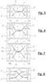
- Fig. 6 a schematic view of a second arrangement of exchanger element 1 and packing 4 is shown.
- the exchanger element 1 here is an asymmetrical countercurrent heat exchanger with a first cross-flow area on the left side and a second cross-flow area on the right side, in which the exhaust air flow path 2 and the supply air flow path 3 intersect.
- a countercurrent area is arranged in between, in which the exhaust air flow path 2 and the supply air flow path 3 are parallel and in opposite directions.
- a first large fan 5 is assigned to a first large outflow area 1a of the exchanger element 1.
- a second large outflow area 1b of the Exchanger element 1 is assigned a second large fan 6.
- a first small air filter 7 is assigned to a first small inflow area 1c of the exchanger element 1.
- a second small air filter 8 is assigned to a second small inflow area 1d of the exchanger element 1.
- Fig. 7 a schematic view of a third arrangement of exchanger element 1 and packing 4 is shown.
- the exchanger element 1 here is also an asymmetrical countercurrent heat exchanger with a first cross-flow area on the left side and a second cross-flow area on the right side, in which the exhaust air flow path 2 and the supply air flow path 3 intersect.
- a countercurrent area is arranged in between, in which the exhaust air flow path 2 and the supply air flow path 3 are parallel and in opposite directions.
- a first small fan 5 is assigned to a first small outflow area 1a of the exchanger element 1.
- a second small fan 6 is assigned to a second small outflow area 1b of the exchanger element 1.
- a first large air filter 7 is assigned to a first large inflow area 1c of the exchanger element 1.
- a second large air filter 8 is assigned to a second large inflow area 1d of the exchanger element 1.
- Fig. 8 a schematic view of a fourth arrangement of exchanger element 1 and packing 4 is shown.
- the exchanger element 1 here is a cross-flow heat exchanger with only one cross-flow area in which the exhaust air flow path 2 and the supply air flow path 3 intersect.
Description
Die Erfindung bezieht sich auf ein mit einem Tauscherelement ausgestatteten Fahrzeug. Ausserdem bezieht sich die Erfindung auf ein Verfahren zum Herstellen einer Tauscherelement-Packung zur Anordnung in einem Bauraum an Bord eines Fahrzeugs, insbesondere in einem einer Fahrgastkabine und/oder einem Motorraum zugeordneten Bauraum, zwischen den Innenwänden des Bauraums und einem in den Bauraum einzubauenden Tauscherelement.The invention relates to a vehicle equipped with an exchanger element. The invention also relates to a method for producing an exchanger element pack for arrangement in an installation space on board a vehicle, in particular in a installation space assigned to a passenger cabin and/or an engine compartment, between the inner walls of the installation space and an exchanger element to be installed in the installation space.
Die Verwendung eines Wärmetauschers zur Heizung von Fahrgastkabinen ist bekannt. Typischerweise verwendet man die Abwärme eines Verbrennungsmotors, um mittels eines Wärmetauschers die in die Fahrgastkabine eingeleitete Zuluft vorzuwärmen. Bei dieser Verwendung ist man auf die Wärmeenergie angewiesen, die bei der Verbrennung des Treibstoffs in dem Verbrennungsmotor anfällt. Die
Ausserdem ist die Verwendung einer Klimaanlage zur Konditionierung der Luft in Fahrzeugkabinen bekannt. Typische Anwendungen sind die Trocknung und/oder Kühlung der in die Fahrgastkabine eingeleiteten Zuluft. Auch bei dieser Verwendung ist man auf Energie, die bei der Verbrennung des Treibstoffs in dem Verbrennungsmotor anfällt, für den Betrieb der Klimaanlage (Kompressor) angewiesen.The use of an air conditioning system for conditioning the air in vehicle cabins is also known. Typical applications are the drying and/or cooling of the supply air introduced into the passenger cabin. With this use, too, one relies on energy that is generated when the fuel is burned in the internal combustion engine to operate the air conditioning system (compressor).
Der Erfindung liegt die Aufgabe zugrunde, das Beheizen oder Klimatisieren eines Fahrzeugbereichs, insbesondere einer Fahrgastkabine und/oder eines Motorraums, mit möglichst geringem oder gar keinem zusätzlichen Energieaufwand zu ermöglichen.The invention is based on the object of enabling the heating or air conditioning of a vehicle area, in particular a passenger cabin and/or an engine compartment, with as little or no additional energy expenditure as possible.
Zur Lösung dieser Aufgabe stellt die Erfindung ein Fahrzeug bereit, dem ein Tauscherelement und eine Packung (4) zugeordnet ist, wobei das Tauscherelement einen Abluft-Strömungsweg sowie einen Zuluft-Strömungsweg aufweist, und wobei der Abluft-Strömungsweg und der Zuluft-Strömungsweg durch Trennwand-Abschnitte voneinander getrennt sind, welche Wärme übertragende Wandbereiche aufweisen, wobei der Abluft-Strömungsweg eine Fluidverbindung vom Innern des Fahrzeugs, insbesondere von der Fahrgastkabine oder vom Motorraum, zur äusseren Umgebung des Fahrzeugs bildet, und wobei der Zuluft-Strömungsweg eine Fluidverbindung von der äusseren Umgebung des Fahrzeugs zu einem Ort an Bord des Fahrzeugs, insbesondere zum Innern der Fahrgastkabine und/oder des Motorraums bildet, dadurch gekennzeichnet, dass das Tauscherelement in die Packung eingebettet ist, deren äussere Oberflächenform komplementär zu den inneren Abmessungen eines Bauraums an Bord des Fahrzeugs, insbesondere in der Fahrgastkabine und/oder im Motorraum, für den Einbau des Tauscherelements ist.To solve this problem, the invention provides a vehicle to which an exchanger element and a packing (4) are assigned, the exchanger element having an exhaust air flow path and a supply air flow path, and wherein the exhaust air flow path and the supply air flow path are separated from one another by partition wall sections which have heat-transferring wall areas, the exhaust air flow path providing a fluid connection from the interior of the vehicle, in particular from the passenger cabin or from Engine compartment, to the external environment of the vehicle, and wherein the supply air flow path forms a fluid connection from the external environment of the vehicle to a location on board the vehicle, in particular to the interior of the passenger cabin and / or the engine compartment, characterized in that the exchanger element in the pack is embedded, the external surface shape of which is complementary to the internal dimensions of an installation space on board the vehicle, in particular in the passenger cabin and / or in the engine compartment, for the installation of the exchanger element.
Das erfindungsgemässe Tauscherelement ermöglicht es, einen Teil der Wärmeenergie der aus dem Fahrzeug austretenden Abluft auf die in das Fahrzeug eintretende Zuluft zu übertragen. Dadurch wird z.B. bei nicht vorhandenem Verbrennungsmotor (reiner Elektroantrieb) oder nicht immer eingeschaltetem Verbrennungsmotor (Hybridantrieb) ein längeres Warmhalten der Fahrgastkabine im Winter ermöglicht. Durch das Einbetten des Tauscherelements in eine Packung, die speziell an den zur Verfügung stehenden Bauraum angepasst ist, wird eine solide Integration des Tauscherelements in den Bauraum an Bord eines Fahrzeugs ermöglicht. Die Packung dient somit einbautechnisch als Schnittstelle zwischen dem Bauraum und dem Tauscherelement. Insbesondere ist die Packung eine Auskleidung zumindest eines Teilbereichs der Fahrgastkabine oder des Motorraums mit Aussparungen für das Tauscherelement. Vorzugsweise dient die Packung oder ein Teil davon zur Festlegung von Luftströmen ausserhalb des Tauscherelements, welche zu dem Tauscherelement hin oder von dem Tauscherelement weg strömen. Neben einer solchen Luftführung oder Lufttrennung ausserhalb des Tauscherelements bewirkt die Packung auch eine Wärmedämmung sowie Schalldämmung.The exchanger element according to the invention makes it possible to transfer part of the thermal energy of the exhaust air leaving the vehicle to the supply air entering the vehicle. This makes it possible to keep the passenger cabin warm for longer in winter, for example if there is no internal combustion engine (pure electric drive) or the internal combustion engine is not always switched on (hybrid drive). By embedding the exchanger element in a pack that is specifically adapted to the available installation space, a solid integration of the exchanger element into the installation space on board a vehicle is made possible. In terms of installation technology, the packing therefore serves as an interface between the installation space and the exchanger element. In particular, the pack is a lining of at least a portion of the passenger cabin or the engine compartment with recesses for the exchanger element. Preferably, the pack or part thereof serves to define air flows outside the exchanger element, which flow towards or away from the exchanger element. In addition to such air guidance or air separation outside the exchanger element, the packing also provides thermal insulation and sound insulation.
Im Folgenden werden die Begriffe «Packung» und «Tauscherelement-Packung» verwendet. Sie haben im Zusammenhang mit der vorliegenden Erfindung dieselbe Bedeutung.The terms “packing” and “exchanger element packing” are used below. They have the same meaning in the context of the present invention.
Bei einer vorteilhaften Ausführung enthält die Packung ein expandiertes und/oder geschäumtes Polymermaterial und/oder ein Fasermaterial, insbesondere aus organischen oder anorganischen Fasern. Besonders vorteilhaft ist es, wenn die Packung vollständig aus einem expandierten und/oder geschäumten Polymermaterial gefertigt ist. Dadurch lässt sich mit geringer Masse eine gute Wärmeisolierung und Schallisolierung für das Tauscherelement erzielen.In an advantageous embodiment, the pack contains an expanded and/or foamed polymer material and/or a fiber material, in particular made of organic or inorganic fibers. It is particularly advantageous if the pack is made entirely of an expanded and/or foamed polymer material. This makes it possible to achieve good thermal insulation and sound insulation for the exchanger element with a low mass.
Um eine für die Wärmeisolierung, die Schallisolierung und die mechanische Dämpfung, insbesondere die Stossdämpfung des Tauscherelements, vorteilhafte Porosität der Packung zu erzielen, kann ein Material mit geschlossenen Poren, insbesondere ein geschäumtes Polymermaterial, und/oder ein Material mit offenen Poren, insbesondere ein organisches oder anorganisches Fasermaterial, verwendet werden.In order to achieve a porosity of the pack that is advantageous for thermal insulation, sound insulation and mechanical damping, in particular the shock absorption of the exchanger element, a material with closed pores, in particular a foamed polymer material, and / or a material with open pores, in particular an organic one or inorganic fiber material can be used.
Als expandiertes Polymermaterial können ein expandiertes Homo-Polymerisat wie z.B. expandiertes Polypropylen (EPP), expandiertes Polystyrol (EPS), expandiertes Polyethylen (EPE) oder expandiertes Polylactid (EPLA) verwendet werden.An expanded homopolymer such as expanded polypropylene (EPP), expanded polystyrene (EPS), expanded polyethylene (EPE) or expanded polylactide (EPLA) can be used as the expanded polymer material.
Gemäss einer ersten Alternative kann als expandiertes Polymermaterial ein expandiertes Co-Polymerisat verwendet werden, welches zumindest eine der Komponenten Propylen, Styrol, Ethylen oder Milchsäure als Komponente aufweist.According to a first alternative, an expanded copolymer can be used as the expanded polymer material, which has at least one of the components propylene, styrene, ethylene or lactic acid as a component.
Gemäss einerzweiten Alternative kann als expandiertes Polymermaterial ein Gemisch aus expandiertem Homo-Polymerisat verwendet werden, welches zumindest eine der Komponenten Polypropylen (PP), Polystyrol (PS), Polyethylen (PE) oder Polylactid (PLA) als Komponente aufweist.According to a second alternative, a mixture of expanded homopolymer can be used as the expanded polymer material, which has at least one of the components polypropylene (PP), polystyrene (PS), polyethylene (PE) or polylactide (PLA) as a component.
Gemäss einer dritten Alternative kann als expandiertes Polymermaterial ein Gemisch aus expandiertem Co-Polymerisat verwendet werden, welches zumindest eine der Komponenten Propylen, Styrol, Ethylen oder Milchsäure als Komponente aufweist.According to a third alternative, a mixture of expanded copolymer can be used as the expanded polymer material, which has at least one of the components propylene, styrene, ethylene or lactic acid as a component.
Gemäss einer vierten Alternative kann als expandiertes Polymermaterial ein Gemisch aus expandiertem Homo-Polymerisat und Co-Polymerisat verwendet werden, welches zumindest eine der Komponenten Propylen, Styrol, Ethylen oder Milchsäure als Komponente aufweist.According to a fourth alternative, a mixture of expanded homopolymer and copolymer can be used as the expanded polymer material at least one of the components propylene, styrene, ethylene or lactic acid as a component.
Das expandierte Polymermaterial kann eine Dichte von 20 bis 120 kg/m3 haben, vorzugsweise von 30 bis 60 kg/m3 und besonders bevorzugt von 40 bis 60 kg/m3.The expanded polymer material may have a density of 20 to 120 kg/m 3 , preferably 30 to 60 kg/m 3 and particularly preferably 40 to 60 kg/m 3 .
Vorzugsweise betragen die Partikeldurchmesser der miteinander verschmolzenen Partikel des expandierten Polymers 2 bis 6 mm. Besonders bevorzugt sind 3 bis 5 mm.Preferably, the particle diameters of the particles of the expanded polymer fused together are 2 to 6 mm. 3 to 5 mm are particularly preferred.
Alternativ kann als Material für die Packung auch Polyurethan verwendet werden, wobei vorzugsweise der innere Teil der Packung Polyurethan-Schaum aufweist und der äussere Teil der Packung massives bzw. weniger geschäumtes Polyurethan aufweist.Alternatively, polyurethane can also be used as the material for the pack, with the inner part of the pack preferably having polyurethane foam and the outer part of the pack having solid or less foamed polyurethane.
Bei einer weiteren vorteilhaften Ausführung enthält die Packung mehrere Packungsteile. Besonders bevorzugt ist eine Packung, welche zwei Packungsteile enthält. Dies ermöglicht den Einbau der Tauscherelements mit seiner Packung in den Bauraum des Fahrzeugs mit nur wenigen Handgriffen.In a further advantageous embodiment, the pack contains several pack parts. A pack which contains two pack parts is particularly preferred. This enables the exchanger element and its packing to be installed in the vehicle's installation space in just a few simple steps.
Zweckmässigerweise enthält die Packung neben dem als Isolierkörper wirkenden expandierten Polymermaterial ein weiteres Polymermaterial, welches das expandierte Polymermaterial der Packung innen und/oder aussen umhüllt, wobei das weitere Polymermaterial vorzugsweise ein weniger expandiertes oder ein kompaktes, nicht-expandiertes Polymermaterial ist. Als Einhausung trägt es zum Schutz des Isolierkörpers vor mechanischer oder chemischer Beschädigung bei.In addition to the expanded polymer material acting as an insulating body, the pack expediently contains a further polymer material which envelops the expanded polymer material of the pack on the inside and/or outside, the further polymer material preferably being a less expanded or a compact, non-expanded polymer material. As an enclosure, it helps protect the insulating body from mechanical or chemical damage.
Als Material der Einhausung kann ein Thermoplast verwendet werden, wie z.B. AcrylnitrilButadien-Styrol (ABS), Polycarbonat (PC), Polypropylen (PP), Polyamid 6 (PA6), Polyamid 66 (PA66), Polyoxymethylen (POM), Acrylnitril-Styrol-Acrylat (ASA), Polystyrol (PS), Polyethylenterephthalat (PET), Polybutylenterephthalat (PBT), etc.A thermoplastic can be used as the material for the enclosure, such as acrylonitrile butadiene styrene (ABS), polycarbonate (PC), polypropylene (PP), polyamide 6 (PA6), polyamide 66 (PA66), polyoxymethylene (POM), acrylonitrile styrene. Acrylate (ASA), Polystyrene (PS), Polyethylene terephthalate (PET), Polybutylene terephthalate (PBT), etc.
Die verwendeten Thermoplaste können mit Füllstoffen versehen sein, wie z.B. Glaskügelchen, Talkum, Mineralstoffen, etc., und/oder können mit Fasern verstärkt sein, wie z.B. Glasfasern, Kohlenstofffasern, Hanffasern, Bambusfasern, etc.The thermoplastics used can be provided with fillers, such as glass beads, talc, minerals, etc., and/or can be reinforced with fibers, such as glass fibers, carbon fibers, hemp fibers, bamboo fibers, etc.
Bei einer weiteren vorteilhaften Ausführung wird das Thermoplast-Material bei der Herstellung der Einhausung physikalisch und/oder chemisch geschäumt. Dadurch übernimmt die Einhausung gleichzeitig die Funktion des Isolierkörpers, wodurch dieser dann als separates Bauteil entfallen kann.In a further advantageous embodiment, the thermoplastic material is physically and/or chemically foamed during the production of the enclosure. This takes over the enclosure also serves the function of the insulating body, which means that it can then be eliminated as a separate component.
Zweckmässigerweise ist die Packung, in welche das Tauscherelement eingebettet ist, mit Ausnahme ihrer Öffnungen für den Zuluft-Strömungsweg und den Abluft-Strömungsweg hermetisch dicht. Zur Erzielung einer hermetischen Abdichtung zwischen dem Tauscherelement und der Packung können Dichtungen aus einem Elastomer-Material, wie z.B. Silikon oder Polyurethan, verwendet werden.The packing in which the exchanger element is embedded is expediently hermetically sealed, with the exception of its openings for the supply air flow path and the exhaust air flow path. To achieve a hermetic seal between the exchanger element and the packing, seals made of an elastomeric material such as silicone or polyurethane can be used.
Zweckmässigerweise enthalten die Packungsteile Befestigungsformationen, mit denen aneinandergrenzende Packungsteile aneinander befestigt werden können. So können die Packungsteile in einem ersten Schritt um das Tauscherelement herum angeordnet und aneinander befestigt werden. Die so zusammengebaute Einheit aus Tauscherelement und Packung kann dann in einem zweiten Schritt in den zur Verfügung stehenden Bauraum eingesetzt werden. Vorzugsweise sind die Befestigungsformationen an dem weiteren, weniger expandierten oder kompakten Polymermaterial der Einhausung befestigt.The packing parts expediently contain fastening formations with which adjacent packing parts can be fastened to one another. In a first step, the packing parts can be arranged around the exchanger element and fastened to one another. The unit assembled in this way consisting of exchanger element and packing can then be inserted into the available installation space in a second step. Preferably, the attachment formations are attached to the further, less expanded or compact polymeric material of the enclosure.
Vorzugsweise ist dem Tauscherelement ein erster Ventilator zugeordnet, der stromauf oder stromab von dem Tauscherelement in dem Zuluft-Strömungsweg angeordnet und in die Packung eingebettet ist.Preferably, the exchanger element is assigned a first fan, which is arranged upstream or downstream of the exchanger element in the supply air flow path and is embedded in the pack.
Vorzugsweise ist dem Tauscherelement ein zweiter Ventilator zugeordnet, der stromauf oder stromab von dem Tauscherelement in dem Abluft-Strömungsweg angeordnet und in die Packung eingebettet ist.Preferably, the exchanger element is assigned a second fan, which is arranged upstream or downstream of the exchanger element in the exhaust air flow path and is embedded in the packing.
Vorzugsweise ist dem Tauscherelement ein erster Luftfilter zugeordnet, der stromaufseitig von dem Tauscherelement in dem Zuluft-Strömungsweg angeordnet und in die Packung eingebettet ist.Preferably, the exchanger element is assigned a first air filter, which is arranged upstream of the exchanger element in the supply air flow path and is embedded in the pack.
Vorzugsweise ist dem Tauscherelement ein zweiter Luftfilter zugeordnet, der stromaufseitig von dem Tauscherelement in dem Abluft-Strömungsweg angeordnet und in die Packung eingebettet ist.Preferably, the exchanger element is assigned a second air filter, which is arranged upstream of the exchanger element in the exhaust air flow path and is embedded in the pack.
Durch das Einbetten solcher Funktionselemente, wie z.B. Ventilator(en) und/oder Luftfilter, wird der Einbau der kompletten Baugruppe, welche das Tauscherelement sowie Ventilatoren und Luftfilter aufweist, noch weiter erleichtert.By embedding such functional elements, such as fan(s) and/or air filters, the installation of the complete assembly, which has the exchanger element as well as fans and air filters, is made even easier.
Zweckmässigerweise enthält das Tauscherelement ein elektrisches Heizelement, das von einem dem Elektroantrieb oder dem Hybridantrieb zugeordneten Akkumulator gespeist werden kann. Dieses elektrische Heizelement kann bei Bedarf aktiviert werden, um das Tauscherelement zu erwärmen, falls es zu einem Einfrieren des Tauscherelements kommen sollte.The exchanger element expediently contains an electrical heating element which can be fed by an accumulator assigned to the electric drive or the hybrid drive. This electrical heating element can be activated as needed to heat the exchanger element should the exchanger element freeze.
Vorzugsweise ist in dem Tauscherelement mindestens ein Temperatursensor zur Erfassung einer Lufttemperatur in dem Tauscherelement enthalten.Preferably, the exchanger element contains at least one temperature sensor for detecting an air temperature in the exchanger element.
Vorzugsweise ist in dem Tauscherelement mindestens ein Feuchtigkeitssensor zur Erfassung einer Luftfeuchtigkeit in dem Tauscherelement enthalten.Preferably, the exchanger element contains at least one moisture sensor for detecting air humidity in the exchanger element.
Vorzugsweise ist in dem Tauscherelement mindestens ein Drucksensor zur Erfassung eines Luftdrucks in dem Tauscherelement enthalten.Preferably, the exchanger element contains at least one pressure sensor for detecting an air pressure in the exchanger element.
Vorzugsweise ist in dem Tauscherelement ein Luftgütesensor enthalten. In einer besonders bevorzugten Ausführung enthält das Tauscherelement einen Sensor für flüchtige organische Verbindungen (VOC-Sensor) und/oder einen Kohlendioxid-Sensor und/oder einen Kohlenmonoxid-Sensor.An air quality sensor is preferably contained in the exchanger element. In a particularly preferred embodiment, the exchanger element contains a volatile organic compound (VOC) sensor and/or a carbon dioxide sensor and/or a carbon monoxide sensor.
Vorzugsweise ist in der Packung eine Steuerungseinheit oder Regelungseinheit enthalten, welche mit mindestens einem der weiter oben genannten Funktionselemente, d.h. Ventilator oder elektrisches Heizelement, sowie mit mindestens einem der weiter oben genannten Sensoren, d.h. Temperatursensor, Feuchtigkeitssensor oder Drucksensor, verbunden ist. Zusammen mit den Sensoren ermöglicht die Steuerungseinheit oder Regelungseinheit einen geregelten Betrieb des Tauscherelements.The pack preferably contains a control unit or regulation unit, which is connected to at least one of the functional elements mentioned above, i.e. fan or electric heating element, and with at least one of the sensors mentioned above, i.e. temperature sensor, humidity sensor or pressure sensor. Together with the sensors, the control unit or regulation unit enables controlled operation of the exchanger element.
Bei einer weiteren vorteilhaften Ausführung enthalten die Trennwand-Abschnitte für Wasserdampf selektiv durchlässige Wandbereiche. Derartige Wandbereiche enthalten vorzugsweise für Wasserdampf selektiv durchlässige Polymermembranen, die auf luftdurchlässigen Trägermaterialien aufgetragen sind. Die selektiv durchlässigen Polymermembranen lassen die relativ kleinen und polaren Wassermoleküle durch das Membranmaterial hindurchtreten, während sie grosse und/oder weniger bis gar nicht polare Moleküle, wie z.B. Moleküle von Sauerstoff, Stickstoff, Kohlendioxid oder Edelgasen oder von relativ grossen Molekülen angenehm oder unangenehm riechender Stoffe, durch das Membranmaterial nicht hindurchtreten lassen. Das erfindungsgemässe Tauscherelement ermöglicht damit einerseits, einen Teil der Luftfeuchtigkeit der aus der Fahrgastkabine austretenden Abluft auf die in die Fahrgastkabine eintretende Zuluft zu übertragen. Dies ermöglicht im Winter zusätzlich zur Aufrechterhaltung einer angenehmen Raumtemperatur auch die Aufrechterhaltung einer angenehmen, ausreichend hohen Luftfeuchtigkeit in der Fahrgastkabine. Das erfindungsgemässe Tauscherelement ermöglicht damit andererseits, einen Teil der Luftfeuchtigkeit der in die Fahrgastkabine eintretenden Zuluft auf die aus der Fahrgastkabine austretenden Abluft zu übertragen. Dies ermöglicht im Sommer zusätzlich zur Aufrechterhaltung einer angenehmen Raumtemperatur auch die Aufrechterhaltung einer angenehmen, ausreichend tiefen Luftfeuchtigkeit in der Fahrgastkabine.In a further advantageous embodiment, the partition wall sections contain wall areas that are selectively permeable to water vapor. Such wall areas preferably contain polymer membranes that are selectively permeable to water vapor and are applied to air-permeable carrier materials. The selectively permeable polymer membranes allow the relatively small and polar water molecules to pass through the membrane material, while they allow large and/or less or non-polar molecules, such as molecules of oxygen, nitrogen, carbon dioxide or noble gases or relatively large molecules of pleasant or unpleasant smelling substances , by the Do not allow membrane material to pass through. On the one hand, the exchanger element according to the invention makes it possible to transfer part of the air humidity of the exhaust air exiting the passenger cabin to the supply air entering the passenger cabin. In winter, in addition to maintaining a pleasant room temperature, this also makes it possible to maintain a pleasant, sufficiently high level of humidity in the passenger cabin. On the other hand, the exchanger element according to the invention makes it possible to transfer part of the air humidity of the supply air entering the passenger cabin to the exhaust air exiting the passenger cabin. In summer, in addition to maintaining a pleasant room temperature, this also makes it possible to maintain a pleasant, sufficiently low level of humidity in the passenger cabin.
Vorzugsweise enthält die Packung Bereiche mit einer ersten Härte und Bereiche mit einer zweiten Härte.Preferably the pack contains areas of a first hardness and areas of a second hardness.
Vorzugsweise hat die Packung am Tauscherelement anliegende Bereiche mit einer grösseren Härte und am Bauraum anliegende Bereiche mit einer kleineren Härte oder hat die Packung am Tauscherelement anliegende Bereiche mit einer kleineren Härte und am Bauraum anliegende Bereiche mit einer grösseren Härte.Preferably, the packing has areas adjacent to the exchanger element with a greater hardness and areas adjacent to the installation space with a smaller hardness, or the packing has areas adjacent to the exchanger element with a lower hardness and areas adjacent to the installation space with a greater hardness.
Diese Massnahmen tragen zur Stossdämpfung bei. Insbesondere die weiter oben beschriebenen expandierten Polymermaterialien sind zwar elastisch, absorbieren aber einen grossen Teil der in das Material bei mechanischer Verformung eingetragenen Verformungsenergie, so dass eine gute Dämpfung erzielt wird.These measures contribute to shock absorption. In particular, the expanded polymer materials described above are elastic, but absorb a large part of the deformation energy introduced into the material during mechanical deformation, so that good damping is achieved.
Durch die Erfindung wird ein Fahrzeug, insbesondere Flugzeug, Schiff, Seilbahn oder Aufzug, insbesondere mit Elektroantrieb oder mit Hybridantrieb oder mit Segelantrieb, bereitgestellt, wobei dem Fahrzeug, insbesondere der Fahrgastkabine und/oder dem Motorraum, ein Tauscherelement und eine Packung der weiter oben beschriebenen Bauart zugeordnet ist.The invention provides a vehicle, in particular an aircraft, ship, cable car or elevator, in particular with an electric drive or with a hybrid drive or with a sail drive, the vehicle, in particular the passenger cabin and/or the engine compartment, being provided with an exchanger element and a packing of the type described above Design is assigned.
In dem Abluft-Strömungsweg und/oder in dem Zuluft-Strömungsweg kann ein Ventilator geschaltet sein, um Abluft entlang des Abluft-Strömungswegs und/oder Zuluft entlang des Zuluft-Strömungswegs zu transportieren.A fan can be connected in the exhaust air flow path and/or in the supply air flow path in order to transport exhaust air along the exhaust air flow path and/or supply air along the supply air flow path.
Vorzugsweise steht der Abluft-Strömungsweg an einem Tiefdruck-Aussenbereich der Fahrgastkabine mit deren äusserer Umgebung in Fluidverbindung. Dadurch kann auch ohne Ventilator die Abluft aus der Fahrgastkabine abgezogen werden.Preferably, the exhaust air flow path is in fluid communication with its external environment at a low-pressure outer area of the passenger cabin. This means that the exhaust air can be extracted from the passenger cabin even without a fan.
Vorzugsweise steht der Zuluft-Strömungsweg an einem Hochdruck-Aussenbereich der Fahrgastkabine mit deren äusserer Umgebung in Fluidverbindung. Dadurch kann auch ohne Ventilator die Zuluft in die Fahrgastkabine hineingedrückt werden.Preferably, the supply air flow path is in fluid communication with its external environment at a high-pressure outer area of the passenger cabin. This means that the supply air can be pushed into the passenger cabin even without a fan.
Vorzugsweise ist in der Fahrgastkabine mindestens ein Temperatursensor zur Erfassung einer Lufttemperatur in der Fahrgastkabine enthalten.The passenger cabin preferably contains at least one temperature sensor for detecting an air temperature in the passenger cabin.
Vorzugsweise ist in der Fahrgastkabine mindestens ein Feuchtigkeitssensor zur Erfassung einer Luftfeuchtigkeit in der Fahrgastkabine enthalten.The passenger cabin preferably contains at least one humidity sensor for detecting air humidity in the passenger cabin.
Vorzugsweise ist in der Fahrgastkabine mindestens ein Drucksensor zur Erfassung eines Luftdrucks in der Fahrgastkabine enthalten.The passenger cabin preferably contains at least one pressure sensor for detecting an air pressure in the passenger cabin.
Zusammen mit den Sensoren in der Fahrgastkabine und/oder den Sensoren in dem Tauscherelement ermöglicht die Steuerungseinheit oder Regelungseinheit einen geregelten Betrieb des Tauscherelements, um angenehme Klimabedingungen in der Fahrgastkabine zu erzielen.Together with the sensors in the passenger cabin and/or the sensors in the exchanger element, the control unit or regulation unit enables controlled operation of the exchanger element in order to achieve pleasant climatic conditions in the passenger cabin.
Wenn das Fahrzeug ein Automobil ist, kann eine Packung mit einem in ihr eingebetteten Tauscherelement an mindestens einem der folgenden Orte des Automobils angeordnet werden: an der Decke der Fahrgastkabine; am Dach des Automobils; an der Frontseite des Automobils; in der A-Säule des Automobils; in der B-Säule des Automobils; in der C-Säule des Automobils; im Heck des Automobils; unter der Motorhaube des Automobils; im Boden des Automobils.If the vehicle is an automobile, a pack with an exchanger element embedded therein may be disposed in at least one of the following locations on the automobile: on the ceiling of the passenger cabin; on the roof of the automobile; on the front of the automobile; in the A-pillar of the automobile; in the B-pillar of the automobile; in the C-pillar of the automobile; in the rear of the automobile; under the hood of the automobile; in the floor of the automobile.
Bei Anordnung der Packung an der Decke bzw. im Dachhimmel der Fahrgastkabine verläuft der Zuluft-Strömungsweg vorzugsweise von einem Eintrittsbereich an der Frontseite des Automobils durch den Motorraum, durch mindestens eine der A-Säulen, durch das Tauscherelement hindurch und schliesslich durch mindestens eine der B-Säulen in den Fussraum der Fahrgastkabine. Der Abluft-Strömungsweg kann vom Kabinenraum durch den Heckbereich, durch mindestens eine der C-Säulen und durch das Tauscherelement hindurch mit einem Austrittsbereich am Fahrzeugdach verlaufen. Alternativ kann der Abluft-Strömungsweg vom Kabinenraum durch mindestens eine der C-Säulen und durch das Tauscherelement hindurch mit einem Austrittsbereich am Fahrzeugdach verlaufen.When the pack is arranged on the ceiling or in the headliner of the passenger cabin, the supply air flow path preferably runs from an entry area on the front of the automobile through the engine compartment, through at least one of the A-pillars, through the exchanger element and finally through at least one of the B -Columns in the footwell of the passenger cabin. The exhaust air flow path can run from the cabin space through the rear area, through at least one of the C-pillars and through the exchanger element with an exit area on the vehicle roof. Alternatively, the exhaust air flow path from the cabin space through at least one of the C-pillars and through the exchanger element with an exit area on the vehicle roof.
Bei Anordnung der Packung an der Frontseite des Automobils verläuft der Zuluft-Strömungsweg vorzugsweise von einem Eintrittsbereich an der Frontseite des Automobils durch das Tauscherelement und durch den Motorraum hindurch in den Kabinenraum. Der Abluft-Strömungsweg kann vom Kabinenraum durch den Motorraum und durch das Tauscherelement hindurch mit einem Austrittsbereich an mindestens einer Fahrzeugseite verlaufen.When the pack is arranged on the front of the automobile, the supply air flow path preferably runs from an entry area on the front of the automobile through the exchanger element and through the engine compartment into the cabin compartment. The exhaust air flow path can run from the cabin compartment through the engine compartment and through the exchanger element with an exit area on at least one side of the vehicle.
Bei Anordnung der Packung in der B-Säule des Automobils verläuft der Zuluft-Strömungsweg vorzugsweise von einem Eintrittsbereich an der Frontseite des Automobils durch den Motorraum, durch mindestens eine der A-Säulen, durch einen Teil des Fahrzeugdaches und schliesslich durch das Tauscherelement hindurch in den Fussraum der Fahrgastkabine. Der Abluft-Strömungsweg kann vom Kabinenraum durch mindestens eine der B-Säulen, durch das Tauscherelement hindurch und durch einen hinteren Teil des Fahrzeugdaches mit einem Austrittsbereich an der Heckseite des Fahrzeugs verlaufen.When the packing is arranged in the B-pillar of the automobile, the supply air flow path preferably runs from an entry area on the front of the automobile through the engine compartment, through at least one of the A-pillars, through part of the vehicle roof and finally through the exchanger element into the Footwell of the passenger cabin. The exhaust air flow path can run from the cabin space through at least one of the B-pillars, through the exchanger element and through a rear part of the vehicle roof with an exit area at the rear of the vehicle.
Bei Anordnung der Packung unter der Motorhaube eines Automobils verläuft der Zuluft-Strömungsweg vorzugsweise von einem Eintrittsbereich an der Frontseite des Automobils durch das Tauscherelement hindurch, durch einen Teil des Motorraum und schliesslich in den vorderen Bereich des Kabinenraums. Der Abluft-Strömungsweg kann vom Kabinenraum durch den Heckbereich, entlang des Bodens des Fahrzeugs in den vorderen Bereich des Kabinenraums und durch das Tauscherelement hindurch mit einem Austrittsbereich an mindestens einer Fahrzeugseite verlaufen.When the pack is arranged under the hood of an automobile, the supply air flow path preferably runs from an entry area on the front of the automobile through the exchanger element, through a part of the engine compartment and finally into the front area of the cabin compartment. The exhaust air flow path can run from the cabin space through the rear area, along the floor of the vehicle into the front area of the cabin area and through the exchanger element with an exit area on at least one side of the vehicle.
Die Erfindung stellt auch ein Verfahren bereit zum Herstellen einer Tauscherelement-Packung zur Anordnung in einem Bauraum an Bord eines Fahrzeugs, insbesondere in einem einer Fahrgastkabine und/oder einem Motorraum zugeordneten Bauraum, zwischen den Innenwänden des Bauraums und einem in den Bauraum einzubauenden Tauscherelement, wobei das Verfahren die folgenden Schritte aufweist:
- a) Bereitstellen eines Tauscherelements;
- b) Erfassen der inneren Abmessungen des Bauraums;
- c) Erfassen der äusseren Abmessungen des Tauscherelements;
- d) Bereitstellen einer Form mit einem Formhohlraum, welcher durch eine äussere Formwand und eine innere Formwand begrenzt ist, wobei die Gestalt der äusseren Formwand durch die inneren Abmessungen bzw. Innenwandbereiche des Bauraums definiert ist und die Gestalt der inneren Formwand durch die äusseren Abmessungen bzw. Aussenwandbereiche des Tauscherelements definiert ist;
- e) partielles Füllen des Formhohlraums mit einem fliessfähigen oder rieselfähigen Material;
- f) Expandieren bzw. Schäumen des fliessfähigen oder rieselfähigen Materials, wobei der Formhohlraum mit dem expandierten bzw. geschäumten Material ausgefüllt wird; und
- g) Öffnen der Form und Entnehmen des expandierten bzw. geschäumten Materials aus dem Formhohlraum als Tauscherelement-Packung, nachdem sich das expandierte bzw. geschäumte Material verfestigt hat.
- a) Providing an exchange element;
- b) recording the internal dimensions of the installation space;
- c) recording the external dimensions of the exchanger element;
- d) Providing a mold with a mold cavity which is delimited by an outer mold wall and an inner mold wall, the shape of the outer mold wall being defined by the inner dimensions or inner wall areas of the installation space and the shape of the inner mold wall being defined by the outer dimensions or Outer wall areas of the exchanger element are defined;
- e) partially filling the mold cavity with a flowable or free-flowing material;
- f) expanding or foaming the flowable or free-flowing material, the mold cavity being filled with the expanded or foamed material; and
- g) Opening the mold and removing the expanded or foamed material from the mold cavity as an exchanger element packing after the expanded or foamed material has solidified.
Die Schritte a), b) und c) werden für jede Art von Fahrgastkabine einmal durchgeführt. Die Schritte d), e), f) und g) werden dann zur Herstellung einer Vielzahl von Tauscherelement-Packungen, die für eine gegebene Fahrgastkabine passend sind, wiederholt durchgeführt.Steps a), b) and c) are carried out once for each type of passenger cabin. Steps d), e), f) and g) are then repeated to produce a plurality of exchanger element packages suitable for a given passenger cabin.
Die Erfindung stellt auch ein alternatives Verfahren bereit zum Herstellen einer Tauscherelement-Packung in einem Bauraum an Bord eines Fahrzeugs, insbesondere in einem einer Fahrgastkabine und/oder einem Motorraum zugeordneten Bauraum, zwischen den Innenwänden des Bauraums und einem in den Bauraum einzubauenden Tauscherelement, wobei das Verfahren die folgenden Schritte aufweist:
- a) Bereitstellen eines Tauscherelements;
- b) Anordnen des Tauscherelements in dem Bauraum, wodurch ein Formhohlraum definiert wird zwischen den inneren Abmessungen bzw. Innenwandbereichen des Bauraums und äusseren Abmessungen bzw. Aussenwandbereichen des Tauscherelements;
- c) Ausschäumen des Formhohlraums mit einem schäumbaren Polymermaterial; und
- d) Warten, bis sich das geschäumte Polymermaterial verfestigt hat.
- a) Providing an exchange element;
- b) arranging the exchanger element in the installation space, whereby a mold cavity is defined between the inner dimensions or inner wall areas of the installation space and outer dimensions or outer wall areas of the exchanger element;
- c) foaming the mold cavity with a foamable polymer material; and
- d) Wait until the foamed polymer material has solidified.
Die Erfindung stellt auch ein weiteres alternatives Verfahren bereit zum Herstellen einer Tauscherelement-Packung zur Anordnung in einem Bauraum an Bord eines Fahrzeugs, insbesondere in einem einer Fahrgastkabine und/oder einem Motorraum zugeordneten Bauraum, zwischen den Innenwänden des Bauraums und einem in den Bauraum einzubauenden Tauscherelement, wobei das Verfahren die folgenden Schritte aufweist:
- a) Bereitstellen eines Tauscherelements;
- b) Erfassen der inneren Abmessungen des Bauraums;
- c) Erfassen der äusseren Abmessungen des Tauscherelements;
- d) Bereitstellen einer Form mit einem Formhohlraum, welcher durch eine äussere Formwand und eine innere Formwand begrenzt ist, wobei die Gestalt der äusseren Formwand durch die inneren Abmessungen bzw. Innenwandbereiche des Bauraums definiert ist und die Gestalt der inneren Formwand durch die äusseren Abmessungen bzw. Aussenwandbereiche des Tauscherelements definiert ist;
- e) Füllen des Formhohlraums mit einem geschmolzenen Material durch Einspritzen des geschmolzenen Materials in den Formhohlraum; und
- f) Öffnen der Form und Entnehmen des eingespritzten Materials aus dem Formhohlraum als Tauscherelement-Packung, nachdem sich das eingespritzte Material verfestigt hat.
- a) Providing an exchange element;
- b) recording the internal dimensions of the installation space;
- c) recording the external dimensions of the exchanger element;
- d) Providing a mold with a mold cavity which is delimited by an outer mold wall and an inner mold wall, the shape of the outer mold wall being defined by the inner dimensions or inner wall areas of the installation space and the shape of the inner mold wall being defined by the outer dimensions or Outer wall areas of the exchanger element are defined;
- e) filling the mold cavity with a molten material by injecting the molten material into the mold cavity; and
- f) Opening the mold and removing the injected material from the mold cavity as an exchanger element packing after the injected material has solidified.
Die Schritte a), b) und c) werden für jede Art von Fahrgastkabine einmal durchgeführt. Die Schritte d), e) und f) werden dann zur Herstellung einer Vielzahl von Tauscherelement-Packungen, die für eine gegebene Fahrgastkabine passend sind, wiederholt durchgeführt.Steps a), b) and c) are carried out once for each type of passenger cabin. Steps d), e) and f) are then repeated to produce a plurality of exchanger element packages suitable for a given passenger cabin.
Ein derartiges Spritzguss-Verfahren kann zur Herstellung der Tauscherelement-Packung als Kompaktspritzguss-Verfahren, als Schaumspritzguss-Verfahren mit physikalischem und/oder chemischem Schäumen, als Gasinnendruck-Spritzgussverfahren oder als Gasgegendruck-Spritzgussverfahren durchgeführt werden.Such an injection molding process can be carried out to produce the exchanger element packing as a compact injection molding process, as a foam injection molding process with physical and/or chemical foaming, as an internal gas pressure injection molding process or as a gas counterpressure injection molding process.
Die Erfindung stellt auch ein noch weiteres alternatives Verfahren bereit zum Herstellen einerTauscherelement-Packung zur Anordnung in einem Bauraum an Bord eines Fahrzeugs, insbesondere in einem einer Fahrgastkabine und/oder einem Motorraum zugeordneten Bauraum, zwischen den Innenwänden des Bauraums und einem in den Bauraum einzubauenden Tauscherelement, wobei das Verfahren die folgenden Schritte aufweist:
- a) Bereitstellen eines Tauscherelements;
- b) Anordnen des Tauscherelements in dem Bauraum, wodurch ein Formhohlraum definiert wird zwischen den inneren Abmessungen bzw. Innenwandbereichen des Bauraums und äusseren Abmessungen bzw. Aussenwandbereichen des Tauscherelements;
- c) Bereitstellen von pulverförmigem oder grobkörnigem, schmelzbaren Baumaterial;
- d) Aufbringen einer das pulverförmige oder grobkörnige Baumaterial aufweisenden Baumaterial-Schicht auf eine Zieloberfläche in einem Baubereich mittels eines Aufbringungsmittels;
- e) gezieltes Einwirkenlassen von Energie auf ausgewählte Stellen der Baumaterial-Schicht, die einem Querschnitt der zu bildenden Tauscherelement-Packung bzw. des Formhohlraums innerhalb der Baumaterial-Schicht entsprechen, um das pulverförmige oder grobkörnige Baumaterial an den ausgewählten Stellen innerhalb der Baumaterial-Schicht und mit einer zuvor aufgebrachten und verschmolzenen Baumaterial-Schicht zu verschmelzen; und
- f) ggfs. Entfernen von nicht verschmolzenem pulverförmigem oder grobkörnigem Baumaterial;
- a) Providing an exchange element;
- b) arranging the exchanger element in the installation space, whereby a mold cavity is defined between the inner dimensions or inner wall areas of the installation space and outer dimensions or outer wall areas of the exchanger element;
- c) Providing powdered or coarse-grained, fusible building material;
- d) applying a layer of building material comprising the powdery or coarse-grained building material to a target surface in a construction area by means of an application agent;
- e) selectively allowing energy to act on selected locations of the building material layer, which correspond to a cross section of the exchanger element packing to be formed or of the mold cavity within the building material layer, in order to move the powdery or coarse-grained building material to the selected locations within the building material layer and to fuse with a previously applied and fused layer of building material; and
- f) if necessary, removal of unfused powdery or coarse-grained building material;
Die Schritte a) und b) werden für jede Art von Fahrgastkabine einmal durchgeführt. Die Schritte c), d), e) und f) werden dann zur Herstellung einer Vielzahl von Tauscherelement-Packungen, die für eine gegebene Fahrgastkabine passend sind, wiederholt durchgeführt.Steps a) and b) are carried out once for each type of passenger cabin. Steps c), d), e) and f) are then repeated to produce a plurality of exchanger element packages suitable for a given passenger cabin.
Je nach Feinheit der Baumaterial-Partikel des pulverförmigen bis grobkörnigen Baumaterials können verschiedene Energiequellen verwendet werden.Depending on the fineness of the building material particles of the powdery to coarse-grained building material, different energy sources can be used.
Vorzugsweise verwendet man für pulverförmiges Baumaterial (mittlere Partikel-Durchmesser kleiner als 1 mm) stark fokussierte Laserstrahlen, d.h. ein Feines Selektives Lasersintern.Preferably, highly focused laser beams are used for powdery building material (average particle diameters less than 1 mm), i.e. fine selective laser sintering.
Vorzugsweise verwendet man für grobkörniges Baumaterial (mittlere Partikel-Durchmesser grösser als 1 mm) weniger stark fokussierte Laserstrahlen, d.h. ein Grobes Selektives Lasersintern. Bei diesem groben selektiven Lasersintern kann grobkörniges Baumaterial verwendet werden, das durch die Einwirkung von Energie, insbesondere von Laserstrahlung und/oder Wärme durch physikalisch und/oder chemisch ausgelöste Gasproduktion in den Baumaterial-Körnern erweicht und/oder schmilzt und dabei expandiert bzw. schäumt, wobei ein Verkleben bzw. Verschmelzen expandierter bzw. geschäumter Partikel innerhalb einer aufgebrachten Schicht und mit einer zuvor aufgebrachten Schicht erzielt wird.For coarse-grained building materials (average particle diameters greater than 1 mm), less strongly focused laser beams are preferably used, i.e. coarse selective laser sintering. In this coarse selective laser sintering, coarse-grained building material can be used, which softens and/or melts through the action of energy, in particular laser radiation and/or heat through physically and/or chemically triggered gas production in the building material grains and thereby expands or foams, wherein a bonding or fusing of expanded or foamed particles is achieved within an applied layer and with a previously applied layer.
Vorzugsweise betragen die Partikeldurchmesser der miteinander verklebten bzw. miteinander verschmolzenen Partikel des expandierten Polymers 2 bis 6 mm. Besonders bevorzugt sind 3 bis 5 mm. Dies hat den Vorteil, dass man bei ausreichender Glattheit der Oberfläche für eine mit diesem additiven Verfahren hergestellte Tauscherelement-Packung kurze Bauzeiten erzielen kann.The particle diameters of the particles of the expanded polymer that are glued or fused together are preferably 2 to 6 mm. 3 to 5 mm are particularly preferred. This has the advantage that short construction times can be achieved if the surface is sufficiently smooth for an exchanger element packing manufactured using this additive process.
Die Erfindung stellt auch ein noch zusätzliches weiteres alternatives Verfahren bereit zum Herstellen einer Tauscherelement-Packung zur Anordnung in einem Bauraum eines Fahrzeugs, insbesondere in einem einer Fahrgastkabine und/oder einem Motorraum zugeordneten Bauraum, zwischen den Innenwänden des Bauraums und einem in den Bauraum einzubauenden Tauscherelement, wobei das Verfahren die folgenden Schritte aufweist:
- a) Bereitstellen eines Tauscherelements;
- b) Anordnen des Tauscherelements in dem Bauraum, wodurch ein Formhohlraum definiert wird zwischen den inneren Abmessungen bzw. Innenwandbereichen des Bauraums und äusseren Abmessungen bzw. Aussenwandbereichen des Tauscherelements;
- c) Bereitstellen von flüssigem oder pastösem, aushärtbarem Baumaterial;
- d) gezieltes Auftragen des flüssigen oder pastösen, aushärtbaren Baumaterials an ausgewählten Stellen als Baumaterial-Schicht auf eine Zieloberfläche in einem Baubereich mittels eines Auftragungsmittels, wobei die Baumaterial-Schicht einem Querschnitt der zu bildenden Tauscherelement-Packung bzw. des Formhohlraums entspricht;
- e) Aushärtenlassen der Baumaterial-Schicht, um das flüssige oder pastöse Baumaterial innerhalb der Baumaterial-Schicht zu verfestigen und mit einer zuvor aufgetragenen und ausgehärteten Baumaterial-Schicht zu verbinden;
- a) Providing an exchange element;
- b) arranging the exchanger element in the installation space, whereby a mold cavity is defined between the inner dimensions or inner wall areas of the installation space and outer dimensions or outer wall areas of the exchanger element;
- c) Providing liquid or pasty, curable building material;
- d) targeted application of the liquid or pasty, curable building material at selected locations as a building material layer on a target surface in a building area by means of an application agent, the building material layer corresponding to a cross section of the exchanger element packing to be formed or of the mold cavity;
- e) allowing the building material layer to harden in order to solidify the liquid or pasty building material within the building material layer and to connect it to a previously applied and hardened building material layer;
Die Schritte a) und b) werden für jede Art von Fahrgastkabine einmal durchgeführt. Die Schritte c), d) und e) werden dann zur Herstellung einer Vielzahl von Tauscherelement-Packungen, die für eine gegebene Fahrgastkabine passend sind, wiederholt durchgeführt.Steps a) and b) are carried out once for each type of passenger cabin. Steps c), d) and e) are then repeated to produce a plurality of exchanger element packages suitable for a given passenger cabin.
Je nach Feinheit bzw. Portionsgrösse des punktförmig und/oder linienförmig aufgetragenen flüssigen oder pastösen Baumaterials können verschiedene Energiequellen verwendet werden.Depending on the fineness or portion size of the liquid or pasty building material applied in dots and/or lines, different energy sources can be used.
Vorzugsweise verwendet man ein grobes Auftragen des Baumaterials (mittlere Tropfen-Durchmesser oder Strang-Durchmesser grösser als 1 mm), d.h. ein Grobes Selektives Auftragen bzw. einen Groben 3D-Druck. Bei diesem groben selektiven Auftragen bzw. groben 3D-Druck kann eine Baumaterial-Masse verwendet werden, die beim Austreten aus einem Baumaterial-Vorratsbehälter über eine Düse und/oder durch die Einwirkung von Energie, insbesondere von Strahlung und/oder Wärme durch physikalisch und/oder chemisch ausgelöste Gasproduktion in der Baumaterial-Masse expandiert bzw. schäumt, wobei ein Verkleben bzw. Verschmelzen expandierter bzw. geschäumter Partikel innerhalb einer aufgebrachten Schicht und mit einer zuvor aufgebrachten Schicht erzielt wird.Preferably, a rough application of the building material is used (average drop diameter or strand diameter greater than 1 mm), ie a rough selective application or a rough 3D printing. In this coarse selective application or coarse 3D printing, a building material mass can be used that emerges from a building material storage container via a nozzle and/or through the action of Energy, in particular from radiation and/or heat, expands or foams through physically and/or chemically triggered gas production in the building material mass, whereby a bonding or fusing of expanded or foamed particles within an applied layer and with a previously applied layer is achieved .
Vorzugsweise betragen auch hier die Durchmesser der miteinander verklebten bzw. miteinander verschmolzenen Tropfen oder Stränge des expandierten bzw. geschäumten Polymers 2 bis 6 mm. Besonders bevorzugt sind 3 bis 5 mm. Dies hat den Vorteil, dass man bei ausreichender Glattheit der Oberfläche auch für eine mit diesem additiven Verfahren hergestellte Tauscherelement-Packung kurze Bauzeiten erzielen kann.Here too, the diameters of the drops or strands of the expanded or foamed polymer which are glued or fused together are preferably 2 to 6 mm. 3 to 5 mm are particularly preferred. This has the advantage that if the surface is sufficiently smooth, short construction times can also be achieved for an exchanger element packing manufactured using this additive process.
Wie weiter oben erwähnt, sind das erfindungsgemässe Tauscherelement bzw. die erfindungsgemässe Fahrgastkabine nicht auf den "Winterbetrieb" (tiefe Aussen-Temperatur und geringe Aussen-Luftfeuchtigkeit) beschränkt, bei dem es darum geht, möglichst viel Wärme und ggfs. Wasserdampf von Personen in der Fahrgastkabine zurückzuhalten. Vielmehr eignet sich das erfindungsgemässe Tauscherelement bzw. die erfindungsgemässe Fahrgastkabine auch für den "Sommerbetrieb" (hohe Aussen-Temperatur und hohe Aussen-Luftfeuchtigkeit), bei dem es darum geht, möglichst viel Wärme und ggfs. Wasserdampf von Personen in der Fahrgastkabine fernzuhalten, d.h. die relativ warme und relativ feuchte Zuluft durch die relativ kühle und relativ trockene Abluft vorzukühlen und ggfs. vorzutrocknen.As mentioned above, the exchanger element according to the invention or the passenger cabin according to the invention are not limited to "winter operation" (low outside temperature and low outside humidity), which involves removing as much heat and possibly water vapor as possible from people in the to restrain the passenger cabin. Rather, the exchanger element according to the invention or the passenger cabin according to the invention is also suitable for "summer operation" (high outside temperature and high outside humidity), in which the aim is to keep as much heat and possibly water vapor away from people in the passenger cabin, i.e. to pre-cool and, if necessary, pre-dry the relatively warm and relatively humid supply air by the relatively cool and relatively dry exhaust air.
Weitere Merkmale, Vorteile und Anwendungsmöglichkeiten der Erfindung ergeben sich aus der nun folgenden Beschreibung nicht einschränkend aufzufassender Ausführungsbeispiele der Erfindung anhand der Zeichnung.Further features, advantages and possible applications of the invention result from the following description of exemplary embodiments of the invention, which are not to be viewed as restrictive, based on the drawing.
Es zeigen:
- Fig. 1
- eine Perspektivansicht des Tauscherelements mit Packung;
- Fig. 2
- eine Schnittansicht des Tauscherelements mit Packung;
- Fig. 3
- eine erste Seitenansicht des Tauscherelements mit Packung;
- Fig. 4
- eine zweite Seitenansicht des Tauscherelements mit Packung;
- Fig. 5
- eine schematische Ansicht einer ersten Tauscherelement/Packung-Anordnung;
- Fig. 6
- eine schematische Ansicht einer zweiten Tauscherelement/Packung-Anordnung;
- Fig. 7
- eine schematische Ansicht einer dritten Tauscherelement/Packung-Anordnung;
- Fig. 8
- eine schematische Ansicht einer vierten Tauscherelement/Packung-Anordnung.
- Fig. 1
- a perspective view of the exchanger element with packing;
- Fig. 2
- a sectional view of the exchanger element with packing;
- Fig. 3
- a first side view of the exchanger element with packing;
- Fig. 4
- a second side view of the exchanger element with packing;
- Fig. 5
- a schematic view of a first exchanger element/packing arrangement;
- Fig. 6
- a schematic view of a second exchanger element/packing arrangement;
- Fig. 7
- a schematic view of a third exchanger element/packing arrangement;
- Fig. 8
- a schematic view of a fourth exchanger element/packing arrangement.
In
Das Tauscherelement 1 ist in eine Packung 4 eingebettet, deren äussere Oberflächenform komplementär zu den inneren Abmessungen eines Bauraums in der Fahrgastkabine für den Einbau des Tauscherelements 1 ist. Die Packung 4 ist aus einem expandierten Polymermaterial gefertigt und besteht aus einem ersten Packungsteil 41 und einem zweiten Packungsteil 42, die je nach Situation symmetrisch zueinander oder sogar identisch sein können oder aber eine ganz spezielle «unförmige» Gestalt haben können, die den Gegebenheiten des zur Verfügung stehenden Bauraums in der Fahrgastkabine angepasst ist.The exchanger element 1 is embedded in a
Dem Tauscherelement 1 ist ein erster Ventilator 5 zugeordnet, der stromab von dem Tauscherelement 1 in dem Zuluft-Strömungsweg 3 angeordnet und in die Packung 4 eingebettet ist. Ausserdem ist dem Tauscherelement 1 ein zweiter Ventilator 6 zugeordnet, der stromab von dem Tauscherelement 1 in dem Abluft-Strömungsweg 2 angeordnet und in die Packung 4 eingebettet ist.The exchanger element 1 is assigned a
Dem Tauscherelement 1 ist ein erster Luftfilter 7 zugeordnet, der stromaufseitig von dem Tauscherelement in dem Zuluft-Strömungsweg 3 angeordnet und in die Packung 4 eingebettet ist. Ausserdem ist dem Tauscherelement 1 ein zweiter Luftfilter 8 zugeordnet, der stromaufseitig von dem Tauscherelement in dem Abluft-Strömungsweg 2 angeordnet und in die Packung 4 eingebettet ist.The exchanger element 1 is assigned a
In
In
In
In
In
Claims (15)
- Vehicle, wherein an exchanger element (1) and a packing (4) are assigned to the vehicle, in particular a passenger compartment and/or an engine bay of the vehicle, wherein the exchanger element comprises an exhaust air flow path (2) and a supply air flow path (3), and wherein the exhaust air flow path and the feed air flow path are separated from one another by partition wall sections which have heat-transferring wall regions, wherein the exhaust air flow path (2) forms a fluid connection from the interior of the vehicle, in particular from the passenger compartment or the engine bay, to the outer surroundings of the vehicle, and wherein the supply air flow path (3) forms a fluid connection from the outer surroundings of the vehicle to a location on board the vehicle, in particular to the interior of the passenger compartment and/or the engine bay, wherein the exchanger element (1) is embedded in a packing (4), whose outer surface shape is complementary to the inner dimensions of an installation space on board the vehicle, in particular in the passenger compartment and/or the engine bay, for the installation of the exchanger element (1).
- Vehicle according to claim 1, characterized in that the packing (4) comprises an expanded and/or foamed polymer material and/or a fiber material, in particular of organic or inorganic fibers, and/or characterized in that the packing (4) comprises several packing parts (41, 42).
- Vehicle according to any one of claims 1 or 2, characterized in that the packing (4) comprises a further polymeric material which inside and/or outside enclose the expanded polymeric material of the packing and wherein preferably the further polymeric material is a less expanded or a compact non-expanded polymeric material.
- Vehicle according to any one of claims 1 to 3, characterized in that a first fan (5) is assigned to the exchanger element, arranged upstream or downstream of the exchanger element in the supply air flow path (3) and embedded in the packing (4); and/or characterized in that a second fan (6) is assigned to the exchanger element, arranged upstream or downstream of the exchanger element in the exhaust air flow path (2) and embedded in the packing (4).
- Vehicle according to any one of the claims 1 to 4, characterized in that a first air filter (7) is assigned to the exchanger element, arranged on the upstream side of the exchanger element in the supply air flow path (3) and embedded in the packing (4); and/or characterized in that a second air filter (8) is assigned to the exchanger element, arranged on the upstream side of the exchanger element in the exhaust air flow path (2) and embedded in the packing (4).
- Vehicle according to any one of claims 1 to 5, characterized in that the partition sections have wall regions selectively permeable to water vapor.
- Vehicle according to any one of claims 1 to 6, characterized in that the packing (4) has regions with a first hardness and regions with a second hardness, wherein preferably the packing (4) has regions adjacent to the exchanger element with a greater hardness and regions adjacent the installation space with less hardness, or that the packing (4) has regions adjacent the exchanger element with less hardness and regions adjacent the installation space with a greater hardness.
- Vehicle according to any one of the preceding claims, wherein the vehicle is an automobile and the one packing (4) with an exchanger element (1) embedded therein is disposed in at least one of the following locations of the automobile: on the ceiling of the passenger compartment; on the roof of the automobile; on the front side of the automobile; in the A-pillar of the automobile; in the B-pillar of the automobile; in the C-pillar of the automobile; in the rear of the automobile; under the hood of the automobile; in the floor of the automobile.
- Vehicle according to claim 8, characterized in that the exhaust air flow path (2) is in fluid connection with the outer surroundings of the vehicle at a low-pressure external region of the vehicle; and/or characterized in that the supply air flow path (3) is in fluid connection with the outer surroundings of the vehicle at a high-pressure external region of the vehicle.
- Vehicle according to one of claims 8 or 9, characterized in that the exchanger element (1) comprises an electric heating element, which can be fed by an accumulator assigned with the electric drive or the hybrid drive.
- Method for producing an exchanger element packing (4) for arrangement in an installation space on board a vehicle, in particular in an installation space assigned with a passenger compartment and/or an engine bay, between the inner walls of the installation space and an exchanger element (1) to be installed in the installation space, wherein the method comprises the following steps:a) providing an exchanger element;b) detecting the inner dimensions of the installation space;c) detecting the outer dimensions of the exchanger element;d) providing a mold with a mold cavity, which is limited by an outer mold wall and an inner mold wall, wherein the shape of the outer mold wall is defined by the inner dimensions or inner wall regions of the installation space and the shape of the inner mold wall is defined by the outer dimensions or outer wall regions of the exchanger element;e) partial filling of the mold cavity with a flowable or pourable material;f) expanding or foaming of the flowable or pourable material, whereby the mold cavity is filled with the expanded or foamed material; andg) opening the mold and removing the expanded or foamed material from the mold cavity as an exchanger element packing (4) after the expanded or foamed material has solidified.
- Method for producing an exchanger element packing (4) in an installation space on board a vehicle, in particular in an installation space assigned with a passenger compartment and/or an engine bay, between the inner walls of the installation space and an exchanger element (1) to be installed in the installation space, wherein the method comprises the following steps:a) providing an exchanger element;b) arranging the exchanger element in the installation space, thereby defining a mold cavity between the inner dimensions or inner wall regions of the installation space and outer dimensions or outer wall regions of the exchanger element;c) foaming the mold cavity with a foamable polymer material; andd) waiting until the foamed polymer material has solidified.
- Method for producing an exchanger element packing (4) for arrangement in an installation space on board a vehicle, in particular in an installation space assigned with a passenger compartment and/or an engine bay, between the inner walls of the installation space and an exchanger element (1) to be installed in the installation space, wherein the method comprises the following steps:a) providing an exchanger element;b) detecting the inner dimensions of the installation space;c) detecting the outer dimensions of the exchanger element;d) providing a mold with a mold cavity limited by an outer mold wall and an inner mold wall, wherein the shape of the outer mold wall is defined by the inner dimensions or inner wall regions of the installation space and the shape of the inner mold wall is defined by the outer dimensions or outer wall regions of the exchanger element;e) filling the mold cavity with a molten material by injecting the molten material into the mold cavity; andf) opening the mold and removing the injected material from the mold cavity as an exchanger element packing (4) after the injected material has solidified.
- Method for producing an exchanger element package (4) for arrangement in an installation space on board a vehicle, in particular in an installation space assigned with a passenger compartment and/or an engine bay, between the inner walls of the installation space and an exchanger element (1) to be installed in the installation space, wherein the method comprises the following steps:a) providing an exchanger element;b) arranging the exchanger element in the installation space, whereby a mold cavity is defined between the inner dimensions or inner wall regions of the installation space and outer dimensions or outer wall regions of the exchanger element;c) providing powdery or coarse-grained, fusible building material;d) applying of a building material layer comprising the powdery or coarse-grained building material to a target surface in a building region by means of an application agent;e) selectively applying energy to selected locations of the building material layer corresponding to a cross-section of the exchanger element packing to be formed or of the mold cavity within the building material layer to fuse the powdery or coarse-grained building material at the selected locations; andf) if necessary, removing of non-fused powdery or coarse-grained building material; wherein steps d) and e) are carried out repeatedly to build up the exchanger element packing to be formed layer by layer.
- Method for producing an exchanger element packing (4) for arrangement in an installation space of a vehicle, in particular in an installation space assigned with a passenger compartment and/or an engine bay, between the inner walls of the installation space and an exchanger element (1) to be installed in the installation space, wherein the method comprises the following steps:a) providing an exchanger element;b) arranging the exchanger element in the installation space, thereby defining a mold cavity between the inner dimensions of inner wall regions of the installation space and outer dimensions or outer wall regions of the exchanger element;c) providing liquid or pasty, curable building material;d) selectively applying the liquid or pasty, curable building material at selected points as a building material layer to a target surface in a building region by means of an applicator, wherein the building material layer corresponds to a cross-section of the exchanger element packing to be formed or of the mold cavity;e) allowing the building material layer to cure to solidify and bond the liquid or pasty building material within the building material layer to a previously applied and cured building material layer;wherein steps d) and e) are performed repeatedly to build up the exchanger element packing to be formed layer by layer.
Applications Claiming Priority (2)
| Application Number | Priority Date | Filing Date | Title |
|---|---|---|---|
| CH4422018 | 2018-04-05 | ||
| PCT/IB2019/052831 WO2019193573A1 (en) | 2018-04-05 | 2019-04-05 | Exchanger element for a vehicle and vehicle equipped with such an exchanger element |
Publications (3)
| Publication Number | Publication Date |
|---|---|
| EP3781421A1 EP3781421A1 (en) | 2021-02-24 |
| EP3781421C0 EP3781421C0 (en) | 2023-10-11 |
| EP3781421B1 true EP3781421B1 (en) | 2023-10-11 |
Family
ID=66668962
Family Applications (1)
| Application Number | Title | Priority Date | Filing Date |
|---|---|---|---|
| EP19727060.6A Active EP3781421B1 (en) | 2018-04-05 | 2019-04-05 | Exchanger element for a vehicle and vehicle equipped with such an exchanger element |
Country Status (7)
| Country | Link |
|---|---|
| US (1) | US20210148597A1 (en) |
| EP (1) | EP3781421B1 (en) |
| JP (1) | JP2021521060A (en) |
| KR (1) | KR20200141052A (en) |
| CN (1) | CN112292275A (en) |
| CA (1) | CA3096238A1 (en) |
| WO (1) | WO2019193573A1 (en) |
Families Citing this family (4)
| Publication number | Priority date | Publication date | Assignee | Title |
|---|---|---|---|---|
| CN112955295A (en) * | 2018-11-05 | 2021-06-11 | 亿康先达国际集团股份有限公司 | Method for providing a housing for a heat exchanger block and heat exchanger block having such a housing |
| EP4242536A1 (en) * | 2022-03-11 | 2023-09-13 | BDR Thermea Group B.V. | Modular air guiding assembly |
| WO2023169927A1 (en) * | 2022-03-11 | 2023-09-14 | Bdr Thermea Group B.V. | Air guiding duct |
| US11920821B1 (en) * | 2023-07-31 | 2024-03-05 | Nu-Air Ventilation Systems Incorporated | Energy recovery ventilator |
Family Cites Families (38)
| Publication number | Priority date | Publication date | Assignee | Title |
|---|---|---|---|---|
| FR1165665A (en) * | 1957-01-23 | 1958-10-28 | Renault | Improvements to vehicle ventilation |
| US3847211A (en) * | 1969-01-28 | 1974-11-12 | Sub Marine Syst Inc | Property interchange system for fluids |
| JPS4819659B1 (en) * | 1969-11-04 | 1973-06-15 | ||
| US4016081A (en) * | 1974-04-22 | 1977-04-05 | Baxter Laboratories, Inc. | Staged membrane diffusion device and membrane support |
| US4110220A (en) * | 1976-10-18 | 1978-08-29 | Lavender Ardis R | Mass transfer device |
| JPS57138413A (en) * | 1981-02-18 | 1982-08-26 | Nippon Soken Inc | Air conditioning ventilator for car |
| US4744414A (en) * | 1986-09-02 | 1988-05-17 | Arco Chemical Company | Plastic film plate-type heat exchanger |
| US4742870A (en) * | 1986-10-29 | 1988-05-10 | Cobe Laboratories | Heat exchanger |
| JPS63152782U (en) * | 1987-03-27 | 1988-10-06 | ||
| FI79810C (en) * | 1988-03-30 | 1990-03-12 | Kalervo Virtanen | UPPVAERMNINGS- OCH LUFTKONDITIONERINGSSYSTEM I EN BUSS. |
| JPH04109292U (en) * | 1991-03-07 | 1992-09-22 | 東洋化学株式会社 | piping cover |
| JPH0662613U (en) * | 1993-01-29 | 1994-09-02 | 株式会社小電力高速通信研究所 | Car antenna |
| JP3651938B2 (en) * | 1994-10-24 | 2005-05-25 | 松下エコシステムズ株式会社 | Heat exchange element |
| US20050145372A1 (en) * | 2004-01-02 | 2005-07-07 | Noel Thomas P. | Method and thermally active multi-phase heat transfer apparatus and method for abstracting heat using liquid bi-phase heat exchanging composition |
| US7055575B2 (en) * | 2002-10-18 | 2006-06-06 | Noel Thomas P | Thermally active convection apparatus |
| DE10106045A1 (en) * | 2001-02-09 | 2002-08-29 | Christian Mueller | Foamed plastic component for internal linings or equipment in a vehicle passenger compartment is permeable by gas and/or fluid and incorporates fittings for temperature control |
| DK176335B1 (en) * | 2001-11-13 | 2007-08-20 | Siemens Wind Power As | Process for manufacturing wind turbine blades |
| US20050044712A1 (en) * | 2003-08-28 | 2005-03-03 | Gideon David E. | Sidewall panel integrated with insulation and air ducts |
| ATE382835T1 (en) * | 2003-10-14 | 2008-01-15 | Lg Electronics Inc | HEAT EXCHANGER FOR FAN |
| JP4529799B2 (en) * | 2005-06-01 | 2010-08-25 | 株式会社デンソー | Air conditioning unit |
| WO2007042065A1 (en) * | 2005-10-14 | 2007-04-19 | Truma Gerätetechnick Gmbh & Co. Kg | Air-conditioning unit for mobile devices |
| US8689859B2 (en) * | 2006-10-03 | 2014-04-08 | Mitsubishi Electric Corporation | Total heat exchanging element and total heat exchanger |
| KR20080060932A (en) * | 2006-12-27 | 2008-07-02 | 엘지전자 주식회사 | Heat exchanger for a ventilating apparatus |
| US20100132930A1 (en) * | 2007-05-02 | 2010-06-03 | Creare, Inc. | Flexible Heat/Mass Exchanger |
| DE102009014377A1 (en) * | 2009-03-23 | 2010-09-30 | Airbus Deutschland Gmbh | Aircraft structure with air ducts integrated in structural elements |
| FR2962711B1 (en) * | 2010-07-13 | 2013-03-29 | Airbus Operations Sas | INTERIOR COATING DEVICE OF AN AIRCRAFT CAR INCORPORATING AT LEAST ONE SYSTEM. |
| DE102011085667A1 (en) * | 2011-11-03 | 2013-05-08 | Robert Bosch Gmbh | Air conditioning device and motor vehicle |
| US20140326432A1 (en) * | 2011-12-19 | 2014-11-06 | Dpoint Technologies Inc. | Counter-flow energy recovery ventilator (erv) core |
| US9446540B2 (en) * | 2014-05-06 | 2016-09-20 | Ford Global Technologies, Llc | Hybrid composite utilizing injection-expansion molding |
| JP2016023909A (en) * | 2014-07-24 | 2016-02-08 | 富士電機株式会社 | On-vehicle cooling unit and refrigeration vehicle |
| MX2016005813A (en) * | 2015-05-13 | 2016-11-14 | Ford Global Tech Llc | Hybrid composite utilizing injection-expansion molding. |
| JP2017026561A (en) * | 2015-07-28 | 2017-02-02 | 株式会社オプティコン | Housing, apparatus, lighting device, coaxial lighting device, and method for manufacturing housing |
| DE102015115196B4 (en) * | 2015-09-09 | 2021-10-21 | Denso Automotive Deutschland Gmbh | Ventilation system for a motor vehicle and associated control method |
| JP6390574B2 (en) * | 2015-09-29 | 2018-09-19 | マツダ株式会社 | Transmission and manufacturing method thereof |
| CN107759056A (en) * | 2016-01-26 | 2018-03-06 | 广东欧珀移动通信有限公司 | A kind of cover-plate glass mould |
| CN112955295A (en) * | 2018-11-05 | 2021-06-11 | 亿康先达国际集团股份有限公司 | Method for providing a housing for a heat exchanger block and heat exchanger block having such a housing |
| KR101995250B1 (en) * | 2018-12-05 | 2019-07-02 | 이응기 | A multi-layered polylactic acid foam article manufactured by co-extrusion foaming method and a method for manufacturing the same |
| US20230100049A1 (en) * | 2021-09-28 | 2023-03-30 | Spirit Aerosystems, Inc. | Injection molding of composite parts |
-
2019
- 2019-04-05 CA CA3096238A patent/CA3096238A1/en active Pending
- 2019-04-05 CN CN201980037435.4A patent/CN112292275A/en active Pending
- 2019-04-05 EP EP19727060.6A patent/EP3781421B1/en active Active
- 2019-04-05 WO PCT/IB2019/052831 patent/WO2019193573A1/en active Application Filing
- 2019-04-05 KR KR1020207030409A patent/KR20200141052A/en not_active Application Discontinuation
- 2019-04-05 US US17/045,331 patent/US20210148597A1/en active Pending
- 2019-04-05 JP JP2021503226A patent/JP2021521060A/en active Pending
Also Published As
| Publication number | Publication date |
|---|---|
| KR20200141052A (en) | 2020-12-17 |
| CA3096238A1 (en) | 2019-10-10 |
| US20210148597A1 (en) | 2021-05-20 |
| EP3781421A1 (en) | 2021-02-24 |
| WO2019193573A1 (en) | 2019-10-10 |
| EP3781421C0 (en) | 2023-10-11 |
| CN112292275A (en) | 2021-01-29 |
| JP2021521060A (en) | 2021-08-26 |
Similar Documents
| Publication | Publication Date | Title |
|---|---|---|
| EP3781421B1 (en) | Exchanger element for a vehicle and vehicle equipped with such an exchanger element | |
| EP3022093B1 (en) | Instrument panel for a vehicle | |
| DE102006009134B4 (en) | Improved process for producing a lightweight, soundproofing panel for automobiles and related trim | |
| DE102007020832B4 (en) | Lightweight, sound-insulating panel for a body part of a motor vehicle and method for its production | |
| EP3458311B1 (en) | Mounting element, system and method for producing a mounting element | |
| DE19620919A1 (en) | Instrument panel for a motor vehicle | |
| EP3393743B1 (en) | Method for producing a molded body from a particle foam material | |
| DE69826218T2 (en) | Fuel tank | |
| DE102012216039A1 (en) | Housing for an air conditioner | |
| EP1522472B1 (en) | Wiper blade | |
| WO2018028740A1 (en) | Noise-reducing casing of a fan motor unit of a vacuum cleaner, and vacuum cleaner | |
| DE102011013516A1 (en) | Method for manufacturing mold part e.g. A-column, in cladding part in body construction of automobile, involves processing mold part, where preferential direction of foaming lies perpendicular to propagation direction of foaming material | |
| DE102013208235A1 (en) | Method for spray coating | |
| DE102013207973A1 (en) | Active cushion with gas ducts | |
| DE102004031414B4 (en) | Method of manufacturing an interior fitting system | |
| EP1502726A1 (en) | Materials for moldings | |
| DE10237366A1 (en) | Noise insulating material (1) especially for automobiles, prepared from rubber matrix containing gas-filled hollow bodies and PUR-plastic useful for noise damping in automobiles | |
| DE19833337A1 (en) | Back-injected plastic molding for internal and external vehicle cladding includes open-pore material through which plastic is injected, forming safe non-splintering product fronting e.g. explosively-deployed air bag | |
| DE102015223769A1 (en) | Support device for a body part | |
| DE10106045A1 (en) | Foamed plastic component for internal linings or equipment in a vehicle passenger compartment is permeable by gas and/or fluid and incorporates fittings for temperature control | |
| DE102005049836B4 (en) | A vehicle trim assembly with impact protection structures and method of making the same | |
| DE102018122793B4 (en) | INTERIOR TRIM FOR MOTOR VEHICLES AND METHOD OF MANUFACTURE THE SAME | |
| EP1479547A1 (en) | Housing, particularly air guide housing, and method of producing the same | |
| DE10257754A1 (en) | Air outflow device and method for its production | |
| DE102016108454A1 (en) | Hybrid composite material from geometries of gas injection technology |
Legal Events
| Date | Code | Title | Description |
|---|---|---|---|
| STAA | Information on the status of an ep patent application or granted ep patent |
Free format text: STATUS: THE INTERNATIONAL PUBLICATION HAS BEEN MADE |
|
| PUAI | Public reference made under article 153(3) epc to a published international application that has entered the european phase |
Free format text: ORIGINAL CODE: 0009012 |
|
| STAA | Information on the status of an ep patent application or granted ep patent |
Free format text: STATUS: REQUEST FOR EXAMINATION WAS MADE |
|
| 17P | Request for examination filed |
Effective date: 20201015 |
|
| AK | Designated contracting states |
Kind code of ref document: A1 Designated state(s): AL AT BE BG CH CY CZ DE DK EE ES FI FR GB GR HR HU IE IS IT LI LT LU LV MC MK MT NL NO PL PT RO RS SE SI SK SM TR |
|
| AX | Request for extension of the european patent |
Extension state: BA ME |
|
| DAV | Request for validation of the european patent (deleted) | ||
| DAX | Request for extension of the european patent (deleted) | ||
| STAA | Information on the status of an ep patent application or granted ep patent |
Free format text: STATUS: EXAMINATION IS IN PROGRESS |
|
| 17Q | First examination report despatched |
Effective date: 20220228 |
|
| GRAP | Despatch of communication of intention to grant a patent |
Free format text: ORIGINAL CODE: EPIDOSNIGR1 |
|
| STAA | Information on the status of an ep patent application or granted ep patent |
Free format text: STATUS: GRANT OF PATENT IS INTENDED |
|
| INTG | Intention to grant announced |
Effective date: 20230519 |
|
| GRAS | Grant fee paid |
Free format text: ORIGINAL CODE: EPIDOSNIGR3 |
|
| GRAA | (expected) grant |
Free format text: ORIGINAL CODE: 0009210 |
|
| STAA | Information on the status of an ep patent application or granted ep patent |
Free format text: STATUS: THE PATENT HAS BEEN GRANTED |
|
| AK | Designated contracting states |
Kind code of ref document: B1 Designated state(s): AL AT BE BG CH CY CZ DE DK EE ES FI FR GB GR HR HU IE IS IT LI LT LU LV MC MK MT NL NO PL PT RO RS SE SI SK SM TR |
|
| REG | Reference to a national code |
Ref country code: GB Ref legal event code: FG4D Free format text: NOT ENGLISH |
|
| REG | Reference to a national code |
Ref country code: CH Ref legal event code: EP |
|
| REG | Reference to a national code |
Ref country code: DE Ref legal event code: R096 Ref document number: 502019009636 Country of ref document: DE |
|
| REG | Reference to a national code |
Ref country code: IE Ref legal event code: FG4D Free format text: LANGUAGE OF EP DOCUMENT: GERMAN |
|
| U01 | Request for unitary effect filed |
Effective date: 20231011 |
|
| U07 | Unitary effect registered |
Designated state(s): AT BE BG DE DK EE FI FR IT LT LU LV MT NL PT SE SI Effective date: 20231016 |
|
| PG25 | Lapsed in a contracting state [announced via postgrant information from national office to epo] |
Ref country code: GR Free format text: LAPSE BECAUSE OF FAILURE TO SUBMIT A TRANSLATION OF THE DESCRIPTION OR TO PAY THE FEE WITHIN THE PRESCRIBED TIME-LIMIT Effective date: 20240112 |
|
| PG25 | Lapsed in a contracting state [announced via postgrant information from national office to epo] |
Ref country code: IS Free format text: LAPSE BECAUSE OF FAILURE TO SUBMIT A TRANSLATION OF THE DESCRIPTION OR TO PAY THE FEE WITHIN THE PRESCRIBED TIME-LIMIT Effective date: 20240211 |