EP3781377B1 - Process for preparing layered foamed polymeric materials - Google Patents
Process for preparing layered foamed polymeric materials Download PDFInfo
- Publication number
- EP3781377B1 EP3781377B1 EP19702485.4A EP19702485A EP3781377B1 EP 3781377 B1 EP3781377 B1 EP 3781377B1 EP 19702485 A EP19702485 A EP 19702485A EP 3781377 B1 EP3781377 B1 EP 3781377B1
- Authority
- EP
- European Patent Office
- Prior art keywords
- foamed
- pressure
- layer
- morphology
- polymeric material
- Prior art date
- Legal status (The legal status is an assumption and is not a legal conclusion. Google has not performed a legal analysis and makes no representation as to the accuracy of the status listed.)
- Active
Links
Images








Classifications
-
- B—PERFORMING OPERATIONS; TRANSPORTING
- B29—WORKING OF PLASTICS; WORKING OF SUBSTANCES IN A PLASTIC STATE IN GENERAL
- B29C—SHAPING OR JOINING OF PLASTICS; SHAPING OF MATERIAL IN A PLASTIC STATE, NOT OTHERWISE PROVIDED FOR; AFTER-TREATMENT OF THE SHAPED PRODUCTS, e.g. REPAIRING
- B29C44/00—Shaping by internal pressure generated in the material, e.g. swelling or foaming ; Producing porous or cellular expanded plastics articles
- B29C44/34—Auxiliary operations
- B29C44/3442—Mixing, kneading or conveying the foamable material
- B29C44/3446—Feeding the blowing agent
- B29C44/3453—Feeding the blowing agent to solid plastic material
-
- A—HUMAN NECESSITIES
- A61—MEDICAL OR VETERINARY SCIENCE; HYGIENE
- A61L—METHODS OR APPARATUS FOR STERILISING MATERIALS OR OBJECTS IN GENERAL; DISINFECTION, STERILISATION OR DEODORISATION OF AIR; CHEMICAL ASPECTS OF BANDAGES, DRESSINGS, ABSORBENT PADS OR SURGICAL ARTICLES; MATERIALS FOR BANDAGES, DRESSINGS, ABSORBENT PADS OR SURGICAL ARTICLES
- A61L27/00—Materials for grafts or prostheses or for coating grafts or prostheses
- A61L27/14—Macromolecular materials
- A61L27/18—Macromolecular materials obtained otherwise than by reactions only involving carbon-to-carbon unsaturated bonds
-
- A—HUMAN NECESSITIES
- A61—MEDICAL OR VETERINARY SCIENCE; HYGIENE
- A61L—METHODS OR APPARATUS FOR STERILISING MATERIALS OR OBJECTS IN GENERAL; DISINFECTION, STERILISATION OR DEODORISATION OF AIR; CHEMICAL ASPECTS OF BANDAGES, DRESSINGS, ABSORBENT PADS OR SURGICAL ARTICLES; MATERIALS FOR BANDAGES, DRESSINGS, ABSORBENT PADS OR SURGICAL ARTICLES
- A61L27/00—Materials for grafts or prostheses or for coating grafts or prostheses
- A61L27/28—Materials for coating prostheses
- A61L27/34—Macromolecular materials
-
- A—HUMAN NECESSITIES
- A61—MEDICAL OR VETERINARY SCIENCE; HYGIENE
- A61L—METHODS OR APPARATUS FOR STERILISING MATERIALS OR OBJECTS IN GENERAL; DISINFECTION, STERILISATION OR DEODORISATION OF AIR; CHEMICAL ASPECTS OF BANDAGES, DRESSINGS, ABSORBENT PADS OR SURGICAL ARTICLES; MATERIALS FOR BANDAGES, DRESSINGS, ABSORBENT PADS OR SURGICAL ARTICLES
- A61L27/00—Materials for grafts or prostheses or for coating grafts or prostheses
- A61L27/50—Materials characterised by their function or physical properties, e.g. injectable or lubricating compositions, shape-memory materials, surface modified materials
-
- B—PERFORMING OPERATIONS; TRANSPORTING
- B29—WORKING OF PLASTICS; WORKING OF SUBSTANCES IN A PLASTIC STATE IN GENERAL
- B29C—SHAPING OR JOINING OF PLASTICS; SHAPING OF MATERIAL IN A PLASTIC STATE, NOT OTHERWISE PROVIDED FOR; AFTER-TREATMENT OF THE SHAPED PRODUCTS, e.g. REPAIRING
- B29C44/00—Shaping by internal pressure generated in the material, e.g. swelling or foaming ; Producing porous or cellular expanded plastics articles
- B29C44/02—Shaping by internal pressure generated in the material, e.g. swelling or foaming ; Producing porous or cellular expanded plastics articles for articles of definite length, i.e. discrete articles
- B29C44/04—Shaping by internal pressure generated in the material, e.g. swelling or foaming ; Producing porous or cellular expanded plastics articles for articles of definite length, i.e. discrete articles consisting of at least two parts of chemically or physically different materials, e.g. having different densities
- B29C44/06—Making multilayered articles
-
- B—PERFORMING OPERATIONS; TRANSPORTING
- B29—WORKING OF PLASTICS; WORKING OF SUBSTANCES IN A PLASTIC STATE IN GENERAL
- B29C—SHAPING OR JOINING OF PLASTICS; SHAPING OF MATERIAL IN A PLASTIC STATE, NOT OTHERWISE PROVIDED FOR; AFTER-TREATMENT OF THE SHAPED PRODUCTS, e.g. REPAIRING
- B29C44/00—Shaping by internal pressure generated in the material, e.g. swelling or foaming ; Producing porous or cellular expanded plastics articles
- B29C44/34—Auxiliary operations
- B29C44/3469—Cell or pore nucleation
- B29C44/348—Cell or pore nucleation by regulating the temperature and/or the pressure, e.g. suppression of foaming until the pressure is rapidly decreased
-
- C—CHEMISTRY; METALLURGY
- C08—ORGANIC MACROMOLECULAR COMPOUNDS; THEIR PREPARATION OR CHEMICAL WORKING-UP; COMPOSITIONS BASED THEREON
- C08J—WORKING-UP; GENERAL PROCESSES OF COMPOUNDING; AFTER-TREATMENT NOT COVERED BY SUBCLASSES C08B, C08C, C08F, C08G or C08H
- C08J9/00—Working-up of macromolecular substances to porous or cellular articles or materials; After-treatment thereof
- C08J9/0061—Working-up of macromolecular substances to porous or cellular articles or materials; After-treatment thereof characterized by the use of several polymeric components
-
- C—CHEMISTRY; METALLURGY
- C08—ORGANIC MACROMOLECULAR COMPOUNDS; THEIR PREPARATION OR CHEMICAL WORKING-UP; COMPOSITIONS BASED THEREON
- C08J—WORKING-UP; GENERAL PROCESSES OF COMPOUNDING; AFTER-TREATMENT NOT COVERED BY SUBCLASSES C08B, C08C, C08F, C08G or C08H
- C08J9/00—Working-up of macromolecular substances to porous or cellular articles or materials; After-treatment thereof
- C08J9/04—Working-up of macromolecular substances to porous or cellular articles or materials; After-treatment thereof using blowing gases generated by a previously added blowing agent
- C08J9/12—Working-up of macromolecular substances to porous or cellular articles or materials; After-treatment thereof using blowing gases generated by a previously added blowing agent by a physical blowing agent
- C08J9/122—Hydrogen, oxygen, CO2, nitrogen or noble gases
-
- C—CHEMISTRY; METALLURGY
- C08—ORGANIC MACROMOLECULAR COMPOUNDS; THEIR PREPARATION OR CHEMICAL WORKING-UP; COMPOSITIONS BASED THEREON
- C08J—WORKING-UP; GENERAL PROCESSES OF COMPOUNDING; AFTER-TREATMENT NOT COVERED BY SUBCLASSES C08B, C08C, C08F, C08G or C08H
- C08J9/00—Working-up of macromolecular substances to porous or cellular articles or materials; After-treatment thereof
- C08J9/04—Working-up of macromolecular substances to porous or cellular articles or materials; After-treatment thereof using blowing gases generated by a previously added blowing agent
- C08J9/12—Working-up of macromolecular substances to porous or cellular articles or materials; After-treatment thereof using blowing gases generated by a previously added blowing agent by a physical blowing agent
- C08J9/14—Working-up of macromolecular substances to porous or cellular articles or materials; After-treatment thereof using blowing gases generated by a previously added blowing agent by a physical blowing agent organic
- C08J9/141—Hydrocarbons
-
- C—CHEMISTRY; METALLURGY
- C08—ORGANIC MACROMOLECULAR COMPOUNDS; THEIR PREPARATION OR CHEMICAL WORKING-UP; COMPOSITIONS BASED THEREON
- C08J—WORKING-UP; GENERAL PROCESSES OF COMPOUNDING; AFTER-TREATMENT NOT COVERED BY SUBCLASSES C08B, C08C, C08F, C08G or C08H
- C08J9/00—Working-up of macromolecular substances to porous or cellular articles or materials; After-treatment thereof
- C08J9/04—Working-up of macromolecular substances to porous or cellular articles or materials; After-treatment thereof using blowing gases generated by a previously added blowing agent
- C08J9/12—Working-up of macromolecular substances to porous or cellular articles or materials; After-treatment thereof using blowing gases generated by a previously added blowing agent by a physical blowing agent
- C08J9/14—Working-up of macromolecular substances to porous or cellular articles or materials; After-treatment thereof using blowing gases generated by a previously added blowing agent by a physical blowing agent organic
- C08J9/143—Halogen containing compounds
- C08J9/144—Halogen containing compounds containing carbon, halogen and hydrogen only
- C08J9/146—Halogen containing compounds containing carbon, halogen and hydrogen only only fluorine as halogen atoms
-
- C—CHEMISTRY; METALLURGY
- C08—ORGANIC MACROMOLECULAR COMPOUNDS; THEIR PREPARATION OR CHEMICAL WORKING-UP; COMPOSITIONS BASED THEREON
- C08J—WORKING-UP; GENERAL PROCESSES OF COMPOUNDING; AFTER-TREATMENT NOT COVERED BY SUBCLASSES C08B, C08C, C08F, C08G or C08H
- C08J9/00—Working-up of macromolecular substances to porous or cellular articles or materials; After-treatment thereof
- C08J9/16—Making expandable particles
- C08J9/18—Making expandable particles by impregnating polymer particles with the blowing agent
-
- C—CHEMISTRY; METALLURGY
- C08—ORGANIC MACROMOLECULAR COMPOUNDS; THEIR PREPARATION OR CHEMICAL WORKING-UP; COMPOSITIONS BASED THEREON
- C08J—WORKING-UP; GENERAL PROCESSES OF COMPOUNDING; AFTER-TREATMENT NOT COVERED BY SUBCLASSES C08B, C08C, C08F, C08G or C08H
- C08J9/00—Working-up of macromolecular substances to porous or cellular articles or materials; After-treatment thereof
- C08J9/34—Chemical features in the manufacture of articles consisting of a foamed macromolecular core and a macromolecular surface layer having a higher density than the core
-
- A—HUMAN NECESSITIES
- A61—MEDICAL OR VETERINARY SCIENCE; HYGIENE
- A61L—METHODS OR APPARATUS FOR STERILISING MATERIALS OR OBJECTS IN GENERAL; DISINFECTION, STERILISATION OR DEODORISATION OF AIR; CHEMICAL ASPECTS OF BANDAGES, DRESSINGS, ABSORBENT PADS OR SURGICAL ARTICLES; MATERIALS FOR BANDAGES, DRESSINGS, ABSORBENT PADS OR SURGICAL ARTICLES
- A61L2420/00—Materials or methods for coatings medical devices
- A61L2420/02—Methods for coating medical devices
-
- A—HUMAN NECESSITIES
- A61—MEDICAL OR VETERINARY SCIENCE; HYGIENE
- A61L—METHODS OR APPARATUS FOR STERILISING MATERIALS OR OBJECTS IN GENERAL; DISINFECTION, STERILISATION OR DEODORISATION OF AIR; CHEMICAL ASPECTS OF BANDAGES, DRESSINGS, ABSORBENT PADS OR SURGICAL ARTICLES; MATERIALS FOR BANDAGES, DRESSINGS, ABSORBENT PADS OR SURGICAL ARTICLES
- A61L2430/00—Materials or treatment for tissue regeneration
- A61L2430/02—Materials or treatment for tissue regeneration for reconstruction of bones; weight-bearing implants
-
- A—HUMAN NECESSITIES
- A61—MEDICAL OR VETERINARY SCIENCE; HYGIENE
- A61L—METHODS OR APPARATUS FOR STERILISING MATERIALS OR OBJECTS IN GENERAL; DISINFECTION, STERILISATION OR DEODORISATION OF AIR; CHEMICAL ASPECTS OF BANDAGES, DRESSINGS, ABSORBENT PADS OR SURGICAL ARTICLES; MATERIALS FOR BANDAGES, DRESSINGS, ABSORBENT PADS OR SURGICAL ARTICLES
- A61L2430/00—Materials or treatment for tissue regeneration
- A61L2430/24—Materials or treatment for tissue regeneration for joint reconstruction
-
- A—HUMAN NECESSITIES
- A61—MEDICAL OR VETERINARY SCIENCE; HYGIENE
- A61L—METHODS OR APPARATUS FOR STERILISING MATERIALS OR OBJECTS IN GENERAL; DISINFECTION, STERILISATION OR DEODORISATION OF AIR; CHEMICAL ASPECTS OF BANDAGES, DRESSINGS, ABSORBENT PADS OR SURGICAL ARTICLES; MATERIALS FOR BANDAGES, DRESSINGS, ABSORBENT PADS OR SURGICAL ARTICLES
- A61L2430/00—Materials or treatment for tissue regeneration
- A61L2430/38—Materials or treatment for tissue regeneration for reconstruction of the spine, vertebrae or intervertebral discs
-
- B—PERFORMING OPERATIONS; TRANSPORTING
- B29—WORKING OF PLASTICS; WORKING OF SUBSTANCES IN A PLASTIC STATE IN GENERAL
- B29K—INDEXING SCHEME ASSOCIATED WITH SUBCLASSES B29B, B29C OR B29D, RELATING TO MOULDING MATERIALS OR TO MATERIALS FOR MOULDS, REINFORCEMENTS, FILLERS OR PREFORMED PARTS, e.g. INSERTS
- B29K2023/00—Use of polyalkenes or derivatives thereof as moulding material
-
- B—PERFORMING OPERATIONS; TRANSPORTING
- B29—WORKING OF PLASTICS; WORKING OF SUBSTANCES IN A PLASTIC STATE IN GENERAL
- B29K—INDEXING SCHEME ASSOCIATED WITH SUBCLASSES B29B, B29C OR B29D, RELATING TO MOULDING MATERIALS OR TO MATERIALS FOR MOULDS, REINFORCEMENTS, FILLERS OR PREFORMED PARTS, e.g. INSERTS
- B29K2025/00—Use of polymers of vinyl-aromatic compounds or derivatives thereof as moulding material
- B29K2025/04—Polymers of styrene
- B29K2025/06—PS, i.e. polystyrene
-
- B—PERFORMING OPERATIONS; TRANSPORTING
- B29—WORKING OF PLASTICS; WORKING OF SUBSTANCES IN A PLASTIC STATE IN GENERAL
- B29K—INDEXING SCHEME ASSOCIATED WITH SUBCLASSES B29B, B29C OR B29D, RELATING TO MOULDING MATERIALS OR TO MATERIALS FOR MOULDS, REINFORCEMENTS, FILLERS OR PREFORMED PARTS, e.g. INSERTS
- B29K2067/00—Use of polyesters or derivatives thereof, as moulding material
-
- B—PERFORMING OPERATIONS; TRANSPORTING
- B29—WORKING OF PLASTICS; WORKING OF SUBSTANCES IN A PLASTIC STATE IN GENERAL
- B29K—INDEXING SCHEME ASSOCIATED WITH SUBCLASSES B29B, B29C OR B29D, RELATING TO MOULDING MATERIALS OR TO MATERIALS FOR MOULDS, REINFORCEMENTS, FILLERS OR PREFORMED PARTS, e.g. INSERTS
- B29K2075/00—Use of PU, i.e. polyureas or polyurethanes or derivatives thereof, as moulding material
-
- B—PERFORMING OPERATIONS; TRANSPORTING
- B29—WORKING OF PLASTICS; WORKING OF SUBSTANCES IN A PLASTIC STATE IN GENERAL
- B29K—INDEXING SCHEME ASSOCIATED WITH SUBCLASSES B29B, B29C OR B29D, RELATING TO MOULDING MATERIALS OR TO MATERIALS FOR MOULDS, REINFORCEMENTS, FILLERS OR PREFORMED PARTS, e.g. INSERTS
- B29K2077/00—Use of PA, i.e. polyamides, e.g. polyesteramides or derivatives thereof, as moulding material
-
- C—CHEMISTRY; METALLURGY
- C08—ORGANIC MACROMOLECULAR COMPOUNDS; THEIR PREPARATION OR CHEMICAL WORKING-UP; COMPOSITIONS BASED THEREON
- C08J—WORKING-UP; GENERAL PROCESSES OF COMPOUNDING; AFTER-TREATMENT NOT COVERED BY SUBCLASSES C08B, C08C, C08F, C08G or C08H
- C08J2203/00—Foams characterized by the expanding agent
- C08J2203/06—CO2, N2 or noble gases
-
- C—CHEMISTRY; METALLURGY
- C08—ORGANIC MACROMOLECULAR COMPOUNDS; THEIR PREPARATION OR CHEMICAL WORKING-UP; COMPOSITIONS BASED THEREON
- C08J—WORKING-UP; GENERAL PROCESSES OF COMPOUNDING; AFTER-TREATMENT NOT COVERED BY SUBCLASSES C08B, C08C, C08F, C08G or C08H
- C08J2203/00—Foams characterized by the expanding agent
- C08J2203/14—Saturated hydrocarbons, e.g. butane; Unspecified hydrocarbons
- C08J2203/142—Halogenated saturated hydrocarbons, e.g. H3C-CF3
-
- C—CHEMISTRY; METALLURGY
- C08—ORGANIC MACROMOLECULAR COMPOUNDS; THEIR PREPARATION OR CHEMICAL WORKING-UP; COMPOSITIONS BASED THEREON
- C08J—WORKING-UP; GENERAL PROCESSES OF COMPOUNDING; AFTER-TREATMENT NOT COVERED BY SUBCLASSES C08B, C08C, C08F, C08G or C08H
- C08J2203/00—Foams characterized by the expanding agent
- C08J2203/18—Binary blends of expanding agents
- C08J2203/182—Binary blends of expanding agents of physical blowing agents, e.g. acetone and butane
-
- C—CHEMISTRY; METALLURGY
- C08—ORGANIC MACROMOLECULAR COMPOUNDS; THEIR PREPARATION OR CHEMICAL WORKING-UP; COMPOSITIONS BASED THEREON
- C08J—WORKING-UP; GENERAL PROCESSES OF COMPOUNDING; AFTER-TREATMENT NOT COVERED BY SUBCLASSES C08B, C08C, C08F, C08G or C08H
- C08J2207/00—Foams characterised by their intended use
-
- C—CHEMISTRY; METALLURGY
- C08—ORGANIC MACROMOLECULAR COMPOUNDS; THEIR PREPARATION OR CHEMICAL WORKING-UP; COMPOSITIONS BASED THEREON
- C08J—WORKING-UP; GENERAL PROCESSES OF COMPOUNDING; AFTER-TREATMENT NOT COVERED BY SUBCLASSES C08B, C08C, C08F, C08G or C08H
- C08J2207/00—Foams characterised by their intended use
- C08J2207/10—Medical applications, e.g. biocompatible scaffolds
-
- C—CHEMISTRY; METALLURGY
- C08—ORGANIC MACROMOLECULAR COMPOUNDS; THEIR PREPARATION OR CHEMICAL WORKING-UP; COMPOSITIONS BASED THEREON
- C08J—WORKING-UP; GENERAL PROCESSES OF COMPOUNDING; AFTER-TREATMENT NOT COVERED BY SUBCLASSES C08B, C08C, C08F, C08G or C08H
- C08J2300/00—Characterised by the use of unspecified polymers
- C08J2300/22—Thermoplastic resins
-
- C—CHEMISTRY; METALLURGY
- C08—ORGANIC MACROMOLECULAR COMPOUNDS; THEIR PREPARATION OR CHEMICAL WORKING-UP; COMPOSITIONS BASED THEREON
- C08J—WORKING-UP; GENERAL PROCESSES OF COMPOUNDING; AFTER-TREATMENT NOT COVERED BY SUBCLASSES C08B, C08C, C08F, C08G or C08H
- C08J2300/00—Characterised by the use of unspecified polymers
- C08J2300/24—Thermosetting resins
-
- C—CHEMISTRY; METALLURGY
- C08—ORGANIC MACROMOLECULAR COMPOUNDS; THEIR PREPARATION OR CHEMICAL WORKING-UP; COMPOSITIONS BASED THEREON
- C08J—WORKING-UP; GENERAL PROCESSES OF COMPOUNDING; AFTER-TREATMENT NOT COVERED BY SUBCLASSES C08B, C08C, C08F, C08G or C08H
- C08J2323/00—Characterised by the use of homopolymers or copolymers of unsaturated aliphatic hydrocarbons having only one carbon-to-carbon double bond; Derivatives of such polymers
- C08J2323/02—Characterised by the use of homopolymers or copolymers of unsaturated aliphatic hydrocarbons having only one carbon-to-carbon double bond; Derivatives of such polymers not modified by chemical after treatment
-
- C—CHEMISTRY; METALLURGY
- C08—ORGANIC MACROMOLECULAR COMPOUNDS; THEIR PREPARATION OR CHEMICAL WORKING-UP; COMPOSITIONS BASED THEREON
- C08J—WORKING-UP; GENERAL PROCESSES OF COMPOUNDING; AFTER-TREATMENT NOT COVERED BY SUBCLASSES C08B, C08C, C08F, C08G or C08H
- C08J2325/00—Characterised by the use of homopolymers or copolymers of compounds having one or more unsaturated aliphatic radicals, each having only one carbon-to-carbon double bond, and at least one being terminated by an aromatic carbocyclic ring; Derivatives of such polymers
- C08J2325/02—Homopolymers or copolymers of hydrocarbons
- C08J2325/04—Homopolymers or copolymers of styrene
- C08J2325/06—Polystyrene
-
- C—CHEMISTRY; METALLURGY
- C08—ORGANIC MACROMOLECULAR COMPOUNDS; THEIR PREPARATION OR CHEMICAL WORKING-UP; COMPOSITIONS BASED THEREON
- C08J—WORKING-UP; GENERAL PROCESSES OF COMPOUNDING; AFTER-TREATMENT NOT COVERED BY SUBCLASSES C08B, C08C, C08F, C08G or C08H
- C08J2361/00—Characterised by the use of condensation polymers of aldehydes or ketones; Derivatives of such polymers
- C08J2361/20—Condensation polymers of aldehydes or ketones with only compounds containing hydrogen attached to nitrogen
-
- C—CHEMISTRY; METALLURGY
- C08—ORGANIC MACROMOLECULAR COMPOUNDS; THEIR PREPARATION OR CHEMICAL WORKING-UP; COMPOSITIONS BASED THEREON
- C08J—WORKING-UP; GENERAL PROCESSES OF COMPOUNDING; AFTER-TREATMENT NOT COVERED BY SUBCLASSES C08B, C08C, C08F, C08G or C08H
- C08J2363/00—Characterised by the use of epoxy resins; Derivatives of epoxy resins
-
- C—CHEMISTRY; METALLURGY
- C08—ORGANIC MACROMOLECULAR COMPOUNDS; THEIR PREPARATION OR CHEMICAL WORKING-UP; COMPOSITIONS BASED THEREON
- C08J—WORKING-UP; GENERAL PROCESSES OF COMPOUNDING; AFTER-TREATMENT NOT COVERED BY SUBCLASSES C08B, C08C, C08F, C08G or C08H
- C08J2367/00—Characterised by the use of polyesters obtained by reactions forming a carboxylic ester link in the main chain; Derivatives of such polymers
-
- C—CHEMISTRY; METALLURGY
- C08—ORGANIC MACROMOLECULAR COMPOUNDS; THEIR PREPARATION OR CHEMICAL WORKING-UP; COMPOSITIONS BASED THEREON
- C08J—WORKING-UP; GENERAL PROCESSES OF COMPOUNDING; AFTER-TREATMENT NOT COVERED BY SUBCLASSES C08B, C08C, C08F, C08G or C08H
- C08J2367/00—Characterised by the use of polyesters obtained by reactions forming a carboxylic ester link in the main chain; Derivatives of such polymers
- C08J2367/04—Polyesters derived from hydroxy carboxylic acids, e.g. lactones
-
- C—CHEMISTRY; METALLURGY
- C08—ORGANIC MACROMOLECULAR COMPOUNDS; THEIR PREPARATION OR CHEMICAL WORKING-UP; COMPOSITIONS BASED THEREON
- C08J—WORKING-UP; GENERAL PROCESSES OF COMPOUNDING; AFTER-TREATMENT NOT COVERED BY SUBCLASSES C08B, C08C, C08F, C08G or C08H
- C08J2375/00—Characterised by the use of polyureas or polyurethanes; Derivatives of such polymers
- C08J2375/04—Polyurethanes
-
- C—CHEMISTRY; METALLURGY
- C08—ORGANIC MACROMOLECULAR COMPOUNDS; THEIR PREPARATION OR CHEMICAL WORKING-UP; COMPOSITIONS BASED THEREON
- C08J—WORKING-UP; GENERAL PROCESSES OF COMPOUNDING; AFTER-TREATMENT NOT COVERED BY SUBCLASSES C08B, C08C, C08F, C08G or C08H
- C08J2377/00—Characterised by the use of polyamides obtained by reactions forming a carboxylic amide link in the main chain; Derivatives of such polymers
-
- C—CHEMISTRY; METALLURGY
- C08—ORGANIC MACROMOLECULAR COMPOUNDS; THEIR PREPARATION OR CHEMICAL WORKING-UP; COMPOSITIONS BASED THEREON
- C08J—WORKING-UP; GENERAL PROCESSES OF COMPOUNDING; AFTER-TREATMENT NOT COVERED BY SUBCLASSES C08B, C08C, C08F, C08G or C08H
- C08J2379/00—Characterised by the use of macromolecular compounds obtained by reactions forming in the main chain of the macromolecule a linkage containing nitrogen with or without oxygen, or carbon only, not provided for in groups C08J2361/00 - C08J2377/00
- C08J2379/04—Polycondensates having nitrogen-containing heterocyclic rings in the main chain; Polyhydrazides; Polyamide acids or similar polyimide precursors
- C08J2379/08—Polyimides; Polyester-imides; Polyamide-imides; Polyamide acids or similar polyimide precursors
-
- C—CHEMISTRY; METALLURGY
- C08—ORGANIC MACROMOLECULAR COMPOUNDS; THEIR PREPARATION OR CHEMICAL WORKING-UP; COMPOSITIONS BASED THEREON
- C08J—WORKING-UP; GENERAL PROCESSES OF COMPOUNDING; AFTER-TREATMENT NOT COVERED BY SUBCLASSES C08B, C08C, C08F, C08G or C08H
- C08J2429/00—Characterised by the use of homopolymers or copolymers of compounds having one or more unsaturated aliphatic radicals, each having only one carbon-to-carbon double bond, and at least one being terminated by an alcohol, ether, aldehydo, ketonic, acetal, or ketal radical; Hydrolysed polymers of esters of unsaturated alcohols with saturated carboxylic acids; Derivatives of such polymer
- C08J2429/02—Homopolymers or copolymers of unsaturated alcohols
- C08J2429/04—Polyvinyl alcohol; Partially hydrolysed homopolymers or copolymers of esters of unsaturated alcohols with saturated carboxylic acids
Definitions
- the present invention concerns a process for preparing layered foamed polymeric materials, both in terms of cell morphology and in terms of density.
- the process uses a procedure for the solubilisation of physical foaming agents, necessary for the subsequent foaming, characterised by variable conditions over time. More specifically, the variable conditions over time of the solubilisation step generate non-uniform profiles of the concentrations of the physical foaming agents in the polymer, which, upon foaming, generate correspondingly non-uniform morphologies and densities.
- sintering also known as steam-chest moulding or bead-foaming
- sintering also known as steam-chest moulding or bead-foaming
- pre-foamed beads almost spherical in shape and with dimensions nearing a millimetre
- the final foaming is mainly due to foaming agents, for example pentane, which are still contained in the pre-foamed bead and evolve with heating.
- Some commercial products such as golf balls or sports impact protection devices, are layered products with one or more foamed layers (see, for example, Sullivan et al., US 2015/0283432 and Donzis, US 4486901 ).
- European patent application EP1878450A1 cellular gradient polymer composites are disclosed.
- EP1452191A2 and EP1878450A1 procedures are described for the creation of layered structures via the use of composite materials.
- mixtures of two polymeric materials are used with a concentration gradient varying from a step mainly constituted by a first material to a step mainly constituted by a second component
- EP1878450A1 composite preforms are made using the precise positioning of fillers and/or fibres in a mould together with a foamable polymeric material.
- EP0610953A1 Another procedure is disclosed in EP0610953A1 .
- the most remote portions (with respect to the free surfaces in contact with the foaming agent under pressure, thus the innermost portions) of the samples to be foamed contain a lower concentration of the foaming agent with respect to the portions adjacent to said surfaces (more external portions), in which the concentration of the foaming agent readily reaches equilibrium conditions with the foaming agent's external pressure.
- the internal portion of the sample will be less foamed or lack foam, while the outer portions will be completely foamed.
- the process of the present invention aims to overcome the disadvantages of the methods known in the art.
- the Applicant has observed that the layered foamed structures obtained with the process of the present invention do not present discontinuities at the interface between the layers, but on the contrary show a gradual variation of both the density and morphology of the bubbles present in the foamed material.
- the Applicant has observed that the use of one or more variable conditions over time in the solubilisation step of one or more foaming agents in a polymer generate non-uniform profiles of the concentrations of the foaming agents in the same polymer, which upon foaming correspondingly generate non-uniform morphologies and densities.
- the relation itself indicates the thickness, at each time T after the imposition of the variation itself, within which the effect of the variation is relevant.
- the Applicant has first found that the pressure variation can be appropriately adjusted through the use of a management program capable of causing periodic variations characterised by a certain period T and by the waveform, which can be, for example, sinusoidal, triangular, square, sawtooth, and so on.
- the Applicant has also found that the pressure variation can be appropriately adjusted through the use of a management program capable of operating non-periodic variations, quickly or slowly, following linear, parabolic, exponential, impulsive profiles, and so on.
- the Applicant has found that the variation in the composition of the expanding gas can be suitably adjusted by varying the partial pressures of two or more foaming agents (such as nitrogen and carbon dioxide) characterised by different diffusivities, D.
- two or more foaming agents such as nitrogen and carbon dioxide
- thermo diffusivity a parameter that influences the dynamics of mass transport dependent on the pressure and the composition of the expanding gas to obtain different layers.
- the Applicant has therefore found that, by appropriately designing the solubilisation step by means of periodic variations in the pressure of one or more foaming agents, also by using temperature variations, it is possible to obtain foamed polymers with a multi-layer structure, each layer having a specific and different morphology and density.
- a first object of the present invention is represented by a process for preparing layered foamed polymeric materials by means of the use of one or more foaming agents, where said process comprises the following steps:
- a second object of the present invention is represented by a foamed polymeric material with a multi-layer structure obtained by the process according to the first object of the present invention.
- a third object of the present invention is represented by a foamed polymeric material with a multi-layer structure and uniform composition, where said multi-layer structure comprises at least two layers and where each of said at least two layers has a specific and different morphology and/or density, characterised in that it presents a gradual variation in density and/or morphology at the interface between said at least two layers present in the foamed material.
- the foamed polymeric material in accordance with the third object of the present invention, is characterised in that it does not present discontinuities in morphology and/or density at the interface between said at least two layers.
- a fourth object of the present invention is represented by a manufactured product made wholly or in part with a foamed polymeric material with a multi-layer structure and uniform composition, where said multi-layer structure comprises at least two layers and where each of said at least two layers has a specific and different morphology and/or density, characterised in that it presents a gradual variation in density and/or morphology at the interface between said at least two layers present in the foamed material.
- polymeric material indicates a polymeric material comprising a thermoplastic or thermosetting homo-polymer or co-polymer, or mixtures thereof.
- fluable polymeric material indicates a polymeric material capable of absorbing a foaming agent at a certain temperature and under pressure, allowing the nucleation of bubbles upon the release of the same pressure and resisting the straightening stresses during the growth of the bubbles, up to solidification.
- foaming agent indicates a substance capable of causing the expansion of the polymeric material through the formation of bubbles inside the polymeric material.
- multi-layer structure indicates a structure comprising two or more layers, preferably three or more layers.
- uniform composition indicates a composition consisting of a polymeric material of uniform and constant composition in all its points.
- discontinuity indicates a net and distinct boundary between two adjacent layers, typical of composite materials made by hot junction means or with adhesives of two layers with different structures made separately.
- density indicates the ratio between the weight of a given volume of a layer of polymeric material and this volume.
- morphology indicates the shape, size and number of units per volume of the bubbles formed within the foamed polymeric material.
- foaming agent indicates a polymeric material inside which bubbles have been formed by means of a foaming agent.
- a first object of the present invention is represented by a process for preparing layered foamed polymeric materials by means of the use of one or more foaming agents, where said process comprises the following steps:
- said pressure profile preferably varies over time in a periodic or non-periodic manner.
- said pressure profile preferably varies over time in a periodic manner with a waveform selected from the group consisting of the sinusoidal, triangular, square or sawtooth type, or combinations thereof.
- said pressure profile preferably varies over time in a non-periodic manner following a linear, sectioned, curvilinear, parabolic, exponential, impulsive profile or combinations thereof.
- said pressure profile varies from a minimum pressure equal to atmospheric pressure to a maximum of 300 bars, more preferably from atmospheric pressure to 250 bars, and advantageously from atmospheric pressure to 200 bars.
- said pressure profile preferably comprises at least one step with an increasing pressure profile over time and at least one step with a decreasing pressure profile over time.
- said pressure profile can advantageously comprise at least one step with a constant pressure profile over time.
- the solubilisation step is carried out with a foaming agent or with a mixture of two or more foaming agents, preferably with a mixture of two foaming agents.
- the solubilisation step can be carried out by varying the concentration of the foaming agent over time.
- the concentration of the foaming agents of said mixture can vary over time.
- the solubilisation step is preferably carried out at a temperature comprised between 20° and 350°C, more preferably between 30° and 250°C, and advantageously between 50° and 200°C.
- said one or more foaming agents are selected from the group consisting of inert gases, carbon dioxide, and substituted or not substituted aliphatic hydrocarbons (linear, branched or cyclic), having from 3 to 8 carbon atoms.
- the foaming agent is selected from the group comprising nitrogen, carbon dioxide, n-butane, iso-butane, n-pentane, and iso-pentane.
- the substituted aliphatic hydrocarbons comprise halogenated hydrocarbons, in particular chlorocarbons, chlorofluorocarbons and fluorocarbons, such as, for example, 1,1,1,2-tetrafluoroethane (Freon R-134a), 1,1-difluoroethane (Freon R-152a), difluoromethane (Freon R-32), pentafluoroethane (Freon R-125).
- halogenated hydrocarbons in particular chlorocarbons, chlorofluorocarbons and fluorocarbons, such as, for example, 1,1,1,2-tetrafluoroethane (Freon R-134a), 1,1-difluoroethane (Freon R-152a), difluoromethane (Freon R-32), pentafluoroethane (Freon R-125).
- said polymeric material is preferably selected from the group consisting of thermoplastic or thermosetting polymeric materials.
- thermoplastic polymeric materials are selected from the group which comprises polyolefins, polyurethanes, polyesters and polyamides.
- thermosetting polymeric materials are selected from the group comprising polyurethanes, epoxy resins, melamine resins, polyphenols, and polyimides.
- said polymeric materials are polymers and copolymers of styrene, ethylene, propylene, and other olefins, such as polystyrene, polyethylene, and polypropylene.
- said polymeric materials can comprise one or more co-monomers.
- the co-monomers can include, for example, alkylstyrenes, divinylbenzene, acrylonitrile, diphenylether, alpha-methylstyrene, or combinations thereof.
- the polymeric material can comprise from about 0% by weight to about 30% by weight, preferably from about 0.1 % by weight to about 15% by weight, and more preferably from about 1 % by weight to about 10% by weight of co-monomer.
- the polymeric materials can have a molecular weight Mw (measured by GPC) from about 10,000 Daltons to about 500,000 Daltons, more preferably from about 150,000 Daltons to about 400,000 Daltons, and even more preferably from about 200,000 Daltons to about 350,000 Daltons.
- Mw measured by GPC
- the polymeric materials have a sliding index, measured according to standard ASTM D 1238 at a temperature of 200°C and a load of 10 kg, comprised between 1.0 and 20 g/10 min.
- the polymeric material used in the present invention has a uniform composition for its entire thickness, i.e. it has a uniform and constant composition in all its points.
- the process of the present invention makes it possible to produce multi-layer products with two or more layers while avoiding the use of composite materials comprising a composition gradient as described in EP1452191A2 and EP1878450A1 .
- the process of the present invention advantageously makes it possible to create multiple gradients during the solubilisation procedure of the foaming agent (or of the mixture of foaming agents), thus producing a multi-layer material with three, four, five or even more layers having a different morphology and/or density.
- the pressure is released instantaneously at a speed of no less than 10 bars/s, more preferably no less than 100 bars/s.
- a second object of the present invention is represented by a foamed polymeric material with a multi-layer structure obtained by the process according to the first object of the present invention.
- said foamed polymeric material comprises at least two layers having different density and/or morphology without having discontinuities in morphology and/or density at the interface between said at least two layers.
- said foamed polymeric material comprises at least two layers having different density and/or morphology and has a gradual variation in the density and/or morphology present in the foamed material.
- the foamed polymeric material preferably consists of multi-layer pre-foamed beads or multi-layer foamed sheets.
- said multi-layer foamed sheets comprise at least one layer with lower density and finer morphology and at least one layer with higher density and coarser morphology.
- said multi-layer foamed sheets comprise at least one layer with lower density and coarser morphology and at least one layer with higher density and finer morphology.
- said multi-layer foamed sheets comprise at least one layer with lower density and at least one layer with higher density, with uniform morphology.
- said multi-layer foamed sheets comprise at least one layer with coarser morphology and at least one layer with finer morphology, with uniform density.
- said multi-layer pre-foamed beads comprise at least one non-foamed layer and at least one pre-foamed layer, where said non-foamed layer is in a radially external position with respect to the pre-foamed layer.
- a third object of the present invention is therefore represented by a foamed polymeric material with a multi-layer structure and uniform composition, where said multi-layer structure comprises at least two layers and where each of said at least two layers has a specific and different morphology and/or density, characterised in that it presents a gradual variation in density and / or morphology at the interface between said at least two layers present in the foamed material.
- the foamed polymeric material in accordance with the third object of the present invention, is characterised in that it does not present discontinuities in morphology and density at the interface between said at least two layers.
- said foamed polymeric material comprises at least two layers having different density and/or morphology and having a gradual variation in the density and/or morphology present in the foamed material.
- the multi-layer structure comprises at least three layers, and more particularly comprises three, four, five or more layers with specific and different morphology and/or density.
- the three-layer materials are particularly preferred, the embodiment of which is described in examples 1, 4, 5, and 6, and illustrated in Figures 2C , 5B , 6B , and 7B , as well as the five-layer materials, the embodiment of which is described in examples 2 and 10, and illustrated in Figures 3B and 11B .
- the polymeric material according to the second and third objects of the present invention lends itself to being used for the creation of manufactured products of complex shape with multi-gradient and anisotropic morphology, that is to say with a morphology determined by the porosity.
- a fourth object of the present invention is represented by a manufactured product made wholly or in part with a foamed polymeric material with a multi-layer structure and uniform composition, where said multi-layer structure comprises at least two layers and where each of said at least two layers has a specific and different morphology and/or density, characterised in that it presents a gradual variation in density and/or morphology at the interface between said at least two layers present in the foamed material.
- said multi-layer structure comprises a multi-gradient morphology.
- said multi-layer structure comprises an anisotropic morphology.
- said manufactured product is represented, for example, by protection systems (shin guards, back braces, shoulder and elbow pads, knee pads, shells and pads, bullet-proof vests), helmets and helms, orthopaedic prostheses, dental prostheses, epidermis prostheses, tissue engineering scaffolds, absorption and soundproofing slabs and systems, thermal insulation systems and slabs, soles and elements for sports shoes, panels for cars, sports equipment, furnishings, packaging, filtration membranes and systems, sacrificial foams for ceramic materials and porous metals, foams for diffusers and aerators, biomedical systems, pads and patches for controlled drug delivery, progressive mechanical response systems, progressive functional response systems, electromagnetic shielding systems, catalytic systems, foams for aeronautics and aerospace, foams for optoelectronics, flotation systems, frames and chassis, and glasses frames.
- protection systems shin guards, back braces, shoulder and elbow pads, knee pads, shells and pads, bullet-proof vests
- helmets and helms ortho
- said manufactured product is represented, for example, by orthopaedic prostheses, i.e. medical devices capable of replicating the bone structure of a skeletal segment of a human or animal body with the same structural characteristics.
- orthopaedic prostheses i.e. medical devices capable of replicating the bone structure of a skeletal segment of a human or animal body with the same structural characteristics.
- the orthopaedic prosthesis according to the fourth object of the present invention comprises orthopaedic endoprostheses of the lower limbs (foot, ankle, knee, femur, hip), of the upper limbs (hand, wrist, elbow, humerus, shoulder), and of the vertebral column.
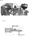
- Figure 1 shows a photograph ( Figure 1A ) and a diagram ( Figure 1B ) of the discontinuous foaming apparatus used in the present invention.
- the reactor is cylindrical, thermoregulated and pressurised, with a volume of 0.3 L (HiP, model BC-1).
- HiP model BC-1
- the reactor was modified to allow the measurement and control of the process parameters of interest.
- an electric heater (11) was used as a heating element and a heat exchanger with an oil bath (12) as a cooling element.
- the heater (11) and the exchanger (12) were controlled by a PID thermoregulator (Ascon, model X1), which read the temperature inside the reactor using a Pt100 probe (4).
- the valve (1) was connected to the expanding gas supply while the valve (2) was connected to a vacuum pump.
- the pressure release system consists of an HiP ball discharge valve, model 15-71 NFB (5), an HiP electromechanical actuator, model 15-72 NFB TSR8 (6), and a solenoid valve (7) connected to the piping for the compressed air (8) and the cable (9) for the solenoid valve actuation signal (7).
- This system allowed the opening of the valve to be reproduced.
- the pressure pattern over time during pressure release, P (t) was recorded using a DAQ PCI6036E data acquisition system, National Instruments, Austin, TX, USA.
- the pressure program was managed by the Teledyne ISCO 500D volumetric pump (Lincoln NE, USA). Through the serial interface of the pump controller it was possible to control the pump via a computer and implement any pressure program. In addition, the controller can handle up to four pumps for different fluids.
- variable condition of the solubilisation step can occur through a variation of the solubilisation pressure of the foaming agent, with a periodic pattern (for example, a triangular or sinusoidal wave), or with a non-periodic pattern (for example, a linear or curvilinear profile), as described in the following examples.
- a periodic pattern for example, a triangular or sinusoidal wave
- a non-periodic pattern for example, a linear or curvilinear profile
- the polymer used is a polystyrene (PS), code N2380, supplied by Versalis SpA (Mantua, Italy) with a mean molecular weight, density and melt flow index respectively equal to 300 kDa, 1.05 g/cm 3 and 2.0 g/10 min at 200°C and 10 kg, respectively.
- PS polystyrene
- code N2380 supplied by Versalis SpA (Mantua, Italy) with a mean molecular weight, density and melt flow index respectively equal to 300 kDa, 1.05 g/cm 3 and 2.0 g/10 min at 200°C and 10 kg, respectively.
- the sample consists of a cylindrical disk of PS with a diameter of 25 mm and thickness of 2.2 mm.
- mass transport occurs in the direction of the cylinder axis and can be studied as a one-dimensional problem.
- the use of the barrier film is, in this case and in those described in examples 2, 3, 4, 5 and 6, in which the sample to be foamed is cylindrical, dictated solely by the need to render the one-dimensional treatment of the material transport more rigorous. It is not considered necessary for the purpose of obtaining the multi-layer structure.
- the sample was housed in the batch foaming system illustrated in Figure 1 and described above, at room temperature. The reactor was then closed and brought to a temperature of 100°C.
- step 3 the pressure was instantaneously released (at a maximum speed of 1000 bars/s) for foaming.
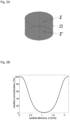
- the concentration profile as calculated using Comsol Multiphysics 10.0 simulation software, using data on CO 2 diffusivity in PS at 100°C reported by Sato et al., in "Solubilities and diffusion coefficients of carbon dioxide in poly(vinyl acetate) and polystyrene", The Journal of Supercritical Fluids 19 (2001) 187-198 , and the geometry described above resulted in that shown in Figure 2B .
- the areas with a high concentration of foaming agent were foamed with a morphology and density depending on the foaming conditions (here in particular the temperature of 100°C, the concentration of about 6% by weight and the pressure release rate of 1000 bars/s), while the central area lacking foaming agent was not foamed, even though it had the same operating conditions as the high concentration areas.
- Figure 2C shows a scanned electron microscope image of the section of the produced foam, with an evident three-layer structure.
- the two areas near the base surfaces were foamed, with a density of about 0.1 g/cm 3 , and minimum pore size of about 20 ⁇ m, while the central area was not foamed.
- the pressure profile comprised four phases:
- step 4 the pressure was instantaneously released (at a maximum speed of 1000 bars/s) for foaming.
- foamed areas were recognised and distinguished in the foamed cylindrical disk, two near the base surfaces, with a high concentration of foaming agent, two intermediate areas with a lesser concentration, and a central area with again a high concentration of foaming agent.
- the areas with a high concentration of foaming agent were foamed (indicated in Figure 3B with "highly foamed area") with a morphology and density depending on the foaming conditions (here in particular the temperature of 100°C, the concentration of about 5% by weight and the pressure release rate of 1000 bars/s), while the two intermediate areas with less foaming agent (concentration of about 3%), had a lower degree of foaming (shown in Figure 3B with "less foamed area").
- Figures 3B-D show some images of the section of foam produced at different magnifications taken with a scanning electron microscope, with a clear five-layer structure.
- the two areas near the base surfaces and the central area were foamed, with a density of about 0.1 g/cm 3 , and pore size of about 20 ⁇ m.
- the two intermediate areas were less foamed, with a density of 0.3g/cm 3 and pore size of about 80 ⁇ m.
- Images 3C and 3D show some enlargements of the transition zones, where the variation in the size of the bubbles can be noted.
- the process of the present invention allows broad freedom in design, differently from the method described in Zhou C. et al., in "Fabrication of functionally graded porous polymer via supercritical CO2 foaming", Composites: Part B 42 (2011) 318-325 .
- step 2 the pressure was instantaneously released (at a maximum speed of 1000 bars/s) for foaming.
- the concentration profile is constant and equal to about 6% by weight of CO 2 .
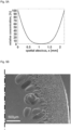
- FIG. 4A A graph showing the concentration values of CO 2 at the end of phase 2 (immediately before foaming), expressed as a percentage with respect to the equilibrium concentration at maximum pressure, as a function of the spatial abscissa "cylinder axis", x, is shown in Figure 4A .
- Figure 4B A scanned electron microscope image of the resulting foam is shown in Figure 4B .
- step 2 the pressure was instantaneously released (at a maximum speed of 1000 bars/s) for foaming.
- the concentration profile is that described by the error function (erf), widely described in scientific and technical literature.
- the concentration of foaming agent in the cylindrical disk progressively changes from the outside to the inside, as described in Zhou C. et al., in "Fabrication of functionally graded porous polymer via supercritical CO2 foaming", Composites: Part B 42 (2011) 318-325 .
- the gas concentration is 6% by weight, while in the inner layer it is null, as the solubilisation time (20 minutes in this case) is much lower than that necessary for complete solubilisation.
- FIG. 5A A graph showing the concentration values of CO 2 at the end of phase 2 (immediately before foaming), expressed as a percentage with respect to the equilibrium concentration at maximum pressure, as a function of the spatial abscissa "cylinder axis", x, is shown in Figure 5A .
- Figure 5B A scanned electron microscope image of the resulting foam is shown in Figure 5B .
- foamed areas can be recognised and distinguished, two near the base surfaces, foamed with a density of about 0.1 g/cm 3 and fine morphology, and a non-foamed central area.
- the foamed area has a non-uniform morphology, with the number of bubbles per unit of volume decreasing gradually from the outer surface towards the inner one (and, correspondingly, a larger bubble size), indicating the lower concentration of gas from the outside inward.
- This type of structure known in the state of the art ( Zhou C.
- step 4 the pressure was instantaneously released (at a maximum speed of 1000 bars/s) for foaming.
- the areas with a high concentration of foaming agent were foamed with a morphology and density depending on the foaming conditions, while the central area lacking foaming agent was not foamed, even though it had the same operating conditions as the high concentration areas.
- Figure 6B shows a scanned electron microscope image of the section of the produced foam, with an evident three-layer structure.
- the two areas near the base surfaces were foamed, with a density of about 0.1 g/cm 3 , and minimum pore size of about 20 ⁇ m, while the central area was not foamed.
- the foamed morphology is more uniform, as a consequence of the outermost area with a constant concentration, and only further inside does the number of bubbles decrease (and the average size increases) as a consequence of the lower concentration of gas.
- step 4 the pressure was instantaneously released (at a maximum speed of 1000 bars/s) for foaming.
- the concentration profile as calculated using Comsol Multiphysics 10.0 simulation software, using data on CO 2 diffusivity in PS at 100°C reported by Sato et al., in "Solubilities and diffusion coefficients of carbon dioxide in poly(vinyl acetate) and polystyrene", The Journal of Supercritical Fluids 19 (2001) 187-198 , and the geometry described above resulted in that shown in Figure 7A .
- the diffusion coefficient of the gas 134a was set much higher than that of the CO 2 , neglecting, for all practical effects, the absorption of 134a in the polymer.
- the areas with a high concentration of foaming agent were foamed with a morphology and density depending on the foaming conditions, while the central area lacking foaming agent was not foamed.
- Figure 7B shows a scanned electron microscope image of the section of the produced foam, with an evident three-layer structure. The two areas near the base surfaces were foamed, but the central area was not foamed. Differently from the case described in Figure 5B , however, in this case the foamed morphology can be described by two gradients, with a density of bubbles, moving from the outside towards the inside, first increasing and then decreasing, corresponding to the pressure profile shown in Figure 7A .
- the polymer used is a polystyrene (PS), code N2380, supplied by Versalis SpA (Mantua, Italy) with a mean molecular weight, density and melt flow index respectively equal to 300 kDa, 1.05 g/cm 3 and 2.0 g/10 min at 200°C and 10 kg, respectively.
- PS polystyrene
- code N2380 supplied by Versalis SpA (Mantua, Italy) with a mean molecular weight, density and melt flow index respectively equal to 300 kDa, 1.05 g/cm 3 and 2.0 g/10 min at 200°C and 10 kg, respectively.
- the sample consists of a sphere of PS with a diameter of 1 mm, schematically shown in Fig. 8 .
- These objects are used to make the so-called pre-foamed beads to be sintered in systems using water vapours to create a finished product downstream of a sintering process of the pre-foamed beads.
- mass transport occurs in the radial direction and can be studied as a one-dimensional problem.
- the sample devoid of any barrier layer was housed in the batch foaming system illustrated in Figure 1 and described above, at room temperature. The reactor was then closed and brought to a temperature of 100°C.
- step 2 the pressure was instantaneously released (at a maximum speed of 1000 bars/s) for foaming.
- the concentration profile is constant and equal to about 6% by weight of CO 2 .
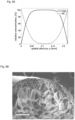
- the gas concentration profile is shown in Figure 8A .
- FIG. 8B A scanned electron microscope image of the resulting foam is shown in Figure 8B .
- step 4 the pressure was instantaneously released (at a maximum speed of 1000 bars/s) for foaming.
- FIG. 9B A scanned electron microscope image of the resulting foam is shown in Figure 9B .
- N 2 has a greater nucleating power than CO 2 , despite the lower concentration (at the same pressure), which determines lower densities in the case of the use of CO 2 .
- the pressure profile comprised four phases:
- step 4 the pressure was instantaneously released (at a maximum speed of 1000 bars/s) for foaming.
- FIG. 10B A scanned electron microscope image of the resulting foam is shown in Figure 10B .
- an outer layer of about 50 micrometres, not foamed, and then a foamed inner core. This morphology cannot be obtained except by varying the saturation conditions.
- This polymer has a carbon dioxide diffusivity of about two orders of magnitude lower than those of the polystyrene in question and can be effectively used to obtain an unsymmetrical concentration profile with respect to the plane, parallel to the base planes, of the centre line of the cylindrical sample.
- This sample was housed in the reactor of the batch foaming system illustrated in Figure 1 and previously described at room temperature. The reactor was then closed and brought to a temperature of 100°C.
- the pressure profile comprised four phases:
- step 4 the pressure was instantaneously released (at a maximum speed of 1000 bars/s) for foaming.
- the areas with a high concentration of foaming agent were more foamed with a morphology and density depending on the foaming conditions, while the areas with a low concentration of foaming agent were less foamed.
- Figure 11B and 11C show a scanned electron microscope image of a section of the foam produced, with an evident unsymmetrical four-layer structure with respect to the centre of the sample (indicated in the image in Figure 11C as the "centre line of the sample").
- a diagram has been inserted that shows the qualitative trend of the pore size at the different areas of the SEM micrograph.
- the vertical dotted lines outline the different areas.
- step 4 the temperature was brought to 40°C, and at the end of step 4 the pressure was instantaneously released (at a maximum speed of 1000 bars/s) for the foaming.
- Figure 12B illustrates a longitudinal section
- Figure 12C illustrates a transversal section
- the similarity with the bone structure of the femur, illustrated in Figure 12D is surprising.
- the straight dotted line of Figure 12D indicates an area of the actual femur structure which is very similar to that shown in Figure 12B of the foamed sample
- the circular line of Figure 12D indicates an area of the actual femur structure which is very similar to that shown in Figure 12C of the foamed sample.
- Note the orientation and the elongated pore shape in Figure 12C just like in an actual femur, obtained during the filling of the mould (the pores follow the flow lines of the polymer during the foaming phase).
Landscapes
- Chemical & Material Sciences (AREA)
- Health & Medical Sciences (AREA)
- Medicinal Chemistry (AREA)
- Chemical Kinetics & Catalysis (AREA)
- Organic Chemistry (AREA)
- Polymers & Plastics (AREA)
- Materials Engineering (AREA)
- Engineering & Computer Science (AREA)
- Transplantation (AREA)
- General Health & Medical Sciences (AREA)
- Public Health (AREA)
- Veterinary Medicine (AREA)
- Animal Behavior & Ethology (AREA)
- Life Sciences & Earth Sciences (AREA)
- Epidemiology (AREA)
- Oral & Maxillofacial Surgery (AREA)
- Dermatology (AREA)
- Manufacture Of Porous Articles, And Recovery And Treatment Of Waste Products (AREA)
- Laminated Bodies (AREA)
- Optical Fibers, Optical Fiber Cores, And Optical Fiber Bundles (AREA)
- Glass Compositions (AREA)
Description
- The present invention concerns a process for preparing layered foamed polymeric materials, both in terms of cell morphology and in terms of density.
- In particular, the process uses a procedure for the solubilisation of physical foaming agents, necessary for the subsequent foaming, characterised by variable conditions over time. More specifically, the variable conditions over time of the solubilisation step generate non-uniform profiles of the concentrations of the physical foaming agents in the polymer, which, upon foaming, generate correspondingly non-uniform morphologies and densities.
- Recently there has been an interest in "gradient" foamed materials, whose structural and functional properties are improved with respect to foamed materials characterised by uniform structures in terms of cell density and/or morphology. This has been demonstrated through recent scientific studies, both theoretical-numerical and experimental. The patent literature describes the use and advantage of such layered foamed structures or those with gradient morphology and/or density. The publication of patent application no.
US2015125663 describes the use of different layers of polymer foams, assembled in a "gradient" manner, in the absorption of energy from impact in helmets. - Another area in which layered foams are of interest is that of expansion for sintering (also known as steam-chest moulding or bead-foaming), which is very common in the production of sintered foamed polystyrene products, but more recently also using, among others, polypropylene, thermoplastic polyurethane and polylactic acid. In this field, pre-foamed beads (almost spherical in shape and with dimensions nearing a millimetre) are used which, in the manufacture of a product, are inserted into a mould and covered with water vapour or hot gases to achieve the final foaming and sintering of the beads. The final foaming is mainly due to foaming agents, for example pentane, which are still contained in the pre-foamed bead and evolve with heating.
- Indeed, the possibility of preventing the loss of the foaming agent via diffusion in the period between pre-foaming and final foaming is of significant technological importance. This loss by diffusion phenomenon is a limit in terms of the conservation of the pre-foamed beads and a process standardisation issue, when products must be produced with beads that have been subject to a different conservation period (seasoning).
- Having a pre-foamed bead available with a radially layered morphology, for example with a dense intermediate or external layer, which acts as a barrier to prevent the loss of the foaming agent in the inner layers, would solve the aforementioned problem.
- Some commercial products, such as golf balls or sports impact protection devices, are layered products with one or more foamed layers (see, for example,
Sullivan et al., US 2015/0283432 andDonzis, US 4486901 ). In European patent applicationEP1878450A1 , cellular gradient polymer composites are disclosed. - The technologies adapted to create such stratified structures, however, appear artificial, long and/or difficult to industrialise.
- For example, Nikhil Gupta et al., in "Comparison of compressive properties of layered syntactic foams having gradient in microballoon volume fraction and wall thickness" Mater. Sci. Eng A 427 (2006) 331-342, describe a laboratory strategy that involves placing hollow glass micro-spheres with different dimensions in the polymer.
- In European patent applications
EP1452191A2 andEP1878450A1 , procedures are described for the creation of layered structures via the use of composite materials. In particular, inEP1452191A2 mixtures of two polymeric materials are used with a concentration gradient varying from a step mainly constituted by a first material to a step mainly constituted by a second component, and inEP1878450A1 composite preforms are made using the precise positioning of fillers and/or fibres in a mould together with a foamable polymeric material. These procedures require both the use of composite materials and a complex preparation and distribution of the components of these materials. Another procedure is disclosed inEP0610953A1 . - More frequently the coupling, by means of bonding or welding, of several layers of foams with different morphologies and/or densities is described and used, as described in
WO2016102291 A1 ,WO2014041516A1 andTW200918316, and by Erheng Wang et al. - Although the process described is simple to manufacture, it is rather limited, as it only allows the construction of single-gradient foamed materials, characterised by less foamed layers inside the sample and more foamed layers outside. The symmetries of the gradient clearly depend on the sample shape and which sample surfaces can be accessed by the foaming agent.
- The process of the present invention aims to overcome the disadvantages of the methods known in the art.
- In particular, the Applicant has observed that with the process of the present invention, layered foamed structures can be obtained with a simple, low-cost process.
- Moreover, the Applicant has observed that the layered foamed structures obtained with the process of the present invention do not present discontinuities at the interface between the layers, but on the contrary show a gradual variation of both the density and morphology of the bubbles present in the foamed material.
- The Applicant has also observed that the process of the present invention makes it possible to obtain layered foamed structures with a wide choice of design, both in terms of number of layers, and of their morphology and density.
- The Applicant has observed that these and other advantages can be obtained by means of a process for preparing layered foamed materials which comprises at least one step of non-equilibrium in the mass transport of a foaming agent in a polymer using at least one variable condition over time in the solubilisation step before the foaming.
- The Applicant has observed that the use of one or more variable conditions over time in the solubilisation step of one or more foaming agents in a polymer generate non-uniform profiles of the concentrations of the foaming agents in the same polymer, which upon foaming correspondingly generate non-uniform morphologies and densities.
- The Applicant has considered that the penetration depth Lpen in the polymer of any variation of the boundary conditions in mass transport characterised by a certain characteristic time T (as, for example, the period of a sine wave) is given by the equation (1):

- If the variation of the boundary conditions in the mass transport is instantaneous, the relation itself indicates the thickness, at each time T after the imposition of the variation itself, within which the effect of the variation is relevant.
- The Applicant has observed that the variation of boundary conditions in mass transport can be substantially influenced by three variables which consist of:
- pressure variations
- variations in the composition of the expanding gas
- temperature variations
- The Applicant has first found that the pressure variation can be appropriately adjusted through the use of a management program capable of causing periodic variations characterised by a certain period T and by the waveform, which can be, for example, sinusoidal, triangular, square, sawtooth, and so on.
- The Applicant has also found that the pressure variation can be appropriately adjusted through the use of a management program capable of operating non-periodic variations, quickly or slowly, following linear, parabolic, exponential, impulsive profiles, and so on.
- Similarly, the Applicant has found that the variation in the composition of the expanding gas can be suitably adjusted by varying the partial pressures of two or more foaming agents (such as nitrogen and carbon dioxide) characterised by different diffusivities, D.
- Finally, the Applicant has observed that temperature variations, whose dynamics follow those of energy transport and are characterised by other properties of the system (thermal diffusivity), can be superimposed/coupled in a calibrated manner to the dynamics of mass transport dependent on the pressure and the composition of the expanding gas to obtain different layers.
- The Applicant has therefore found that, by appropriately designing the solubilisation step by means of periodic variations in the pressure of one or more foaming agents, also by using temperature variations, it is possible to obtain foamed polymers with a multi-layer structure, each layer having a specific and different morphology and density.
- Therefore, a first object of the present invention is represented by a process for preparing layered foamed polymeric materials by means of the use of one or more foaming agents, where said process comprises the following steps:
- providing a foamable polymeric material;
- solubilising said one or more foaming agents in the foamable polymeric material under pressure and at a temperature greater than 20°C; and
- releasing the pressure instantaneously;
- A second object of the present invention is represented by a foamed polymeric material with a multi-layer structure obtained by the process according to the first object of the present invention.
- A third object of the present invention is represented by a foamed polymeric material with a multi-layer structure and uniform composition, where said multi-layer structure comprises at least two layers and where each of said at least two layers has a specific and different morphology and/or density, characterised in that it presents a gradual variation in density and/or morphology at the interface between said at least two layers present in the foamed material.
- In particular, the foamed polymeric material, in accordance with the third object of the present invention, is characterised in that it does not present discontinuities in morphology and/or density at the interface between said at least two layers.
- A fourth object of the present invention is represented by a manufactured product made wholly or in part with a foamed polymeric material with a multi-layer structure and uniform composition, where said multi-layer structure comprises at least two layers and where each of said at least two layers has a specific and different morphology and/or density, characterised in that it presents a gradual variation in density and/or morphology at the interface between said at least two layers present in the foamed material.
-
-
Figure 1A shows a photograph of the discontinuous foaming apparatus used in the present invention. -
Figure 1B shows a diagram of the discontinuous foaming apparatus used in the present invention. -
Figure 2A shows a diagram of the sample used in examples 1-6, with the base surfaces Σ e Σ' and the side surface ,SZ highlighted. -
Figure 2B shows the axial concentration profile of the foaming agent along the entire axial profile of the sample, immediately prior to the release of pressure to allow the foaming used in example 1. -
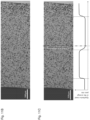
Figure 2C shows a scanning electron microscope photograph of the foam section resulting from the sample subjected to the procedure of example 1 (scale bar equal to 500 µm). For clarity, only half of the sample is shown, symmetrical with respect to the vertical line indicated in the figure. -
Figure 3A shows the axial concentration profile of the foaming agent immediately prior to the release of pressure to allow the foaming used in example 2. -
Figure 3B shows a scanning electron microscope photograph of the foam section resulting from the sample subjected to the procedure of example 2 (scale bar equal to 500 µm). An entire section of the sample is shown to highlight the 5 symmetrical layers. -
Figure 3C shows the same image shown inFigure 3B , with a superimposed graph showing the qualitative trend of the pore size. -
Figure 4A shows the axial concentration profile of the foaming agent along the entire axial profile of the sample, immediately prior to the release of pressure to allow the foaming used in example 3. -
Figure 4B shows a scanning electron microscope photograph of the foam section resulting from the sample subjected to the procedure of example 3 (scale bar equal to 500 µm). -
Figure 5A shows the axial concentration profile of the foaming agent along the entire axial profile of the sample, immediately prior to the release of pressure to allow the foaming used in example 4. -
Figure 5B shows a scanning electron microscope photograph of the foam section resulting from the sample subjected to the procedure of example 4 (scale bar equal to 500 µm). For clarity, only half of the sample is shown, symmetrical with respect to the vertical line indicated in the figure. -
Figure 6A shows the axial concentration profile of the foaming agent immediately prior to the release of pressure to allow the foaming used in example 5. -
Figure 6B shows a scanning electron microscope photograph of the foam section resulting from the sample subjected to the procedure of example 5 (scale bar equal to 500 µm). For clarity, only half of the sample is shown, symmetrical with respect to the vertical line indicated in the figure. -
Figure 7A shows the axial concentration profile of the foaming agent immediately prior to the release of pressure to allow the foaming used in example 6. -
Figure 7B shows a scanning electron microscope photograph of the foam section resulting from the sample subjected to the procedure of example 6 (scale bar equal to 500 µm). For clarity, only half of the sample is shown, symmetrical with respect to the vertical line indicated in the figure. -
Figure 8 shows a diagram of a sample used in examples 7-9, with radius r highlighted. -
Figure 8A shows the axial concentration profile of the foaming agent immediately prior to the release of pressure to allow the foaming used in example 7. -
Figure 8B shows a scanning electron microscope photograph of the foam section resulting from the sample subjected to the procedure of example 7 (scale bar equal to 200 µm). -
Figure 9A shows the axial concentration profile of the foaming agent immediately prior to the release of pressure to allow the foaming used in example 8. -
Figure 9B shows a scanning electron microscope photograph of the foam section resulting from the sample subjected to the procedure of example 8 (scale bar equal to 200 µm). -
Figure 10A shows the axial concentration profile of the foaming agent immediately prior to the release of pressure to allow the foaming used in example 9. -
Figure 10B shows a scanning electron microscope photograph of the foam section resulting from the sample subjected to the procedure of example 9 (scale bar equal to 100 µm). -
Figure 11A shows the axial concentration profile of the foaming agent along the entire axial profile of the sample, immediately prior to the release of pressure to allow the foaming used in example 10. -
Figure 11B and 11C show a scanning electron microscope photograph of the foam section resulting from the sample subjected to the procedure of example 10 (scale bar equal to 500 µm). An entire section of the sample is shown to highlight the 4 non-symmetrical layers. InFigure 11C a diagram has been inserted showing the qualitative trend of the pore size at the different areas of the SEM micrograph. -
Figure 12A shows a porous metal container having the shape of the upper end portion of the femur used in example 11. -
Figure 12B shows a scanning electron microscope photograph of the longitudinal foam section resulting from the sample subjected to the procedure of example 11 (scale bar equal to 1 mm). -
Figure 12C shows a scanning electron microscope photograph of the transversal foam section resulting from the sample subjected to the procedure of example 11 (scale bar equal to 1 mm). -
Figure 12D shows a transversal section of the head of a femur. - The expression "polymeric material" indicates a polymeric material comprising a thermoplastic or thermosetting homo-polymer or co-polymer, or mixtures thereof. The expression "foamable polymeric material" indicates a polymeric material capable of absorbing a foaming agent at a certain temperature and under pressure, allowing the nucleation of bubbles upon the release of the same pressure and resisting the straightening stresses during the growth of the bubbles, up to solidification.
- The expression "foaming agent" indicates a substance capable of causing the expansion of the polymeric material through the formation of bubbles inside the polymeric material.
- The expression "multi-layer structure" indicates a structure comprising two or more layers, preferably three or more layers.
- The expression "uniform composition" indicates a composition consisting of a polymeric material of uniform and constant composition in all its points.
- The term "discontinuity" indicates a net and distinct boundary between two adjacent layers, typical of composite materials made by hot junction means or with adhesives of two layers with different structures made separately.
- The term "density" indicates the ratio between the weight of a given volume of a layer of polymeric material and this volume.
- The term "morphology" indicates the shape, size and number of units per volume of the bubbles formed within the foamed polymeric material.
- The term "foamed polymeric material" indicates a polymeric material inside which bubbles have been formed by means of a foaming agent.
- A first object of the present invention is represented by a process for preparing layered foamed polymeric materials by means of the use of one or more foaming agents, where said process comprises the following steps:
- providing a foamable polymeric material;
- solubilising said one or more foaming agents in the foamable polymeric material under pressure and at a temperature greater than 20°C; and
- releasing the pressure instantaneously;
- In accordance with the first object of the invention, said pressure profile preferably varies over time in a periodic or non-periodic manner.
- In accordance with the first object of the invention, said pressure profile preferably varies over time in a periodic manner with a waveform selected from the group consisting of the sinusoidal, triangular, square or sawtooth type, or combinations thereof.
- In accordance with the first object of the invention, said pressure profile preferably varies over time in a non-periodic manner following a linear, sectioned, curvilinear, parabolic, exponential, impulsive profile or combinations thereof.
- In accordance with the first object of the invention, said pressure profile varies from a minimum pressure equal to atmospheric pressure to a maximum of 300 bars, more preferably from atmospheric pressure to 250 bars, and advantageously from atmospheric pressure to 200 bars.
- In accordance with the first object of the invention, said pressure profile preferably comprises at least one step with an increasing pressure profile over time and at least one step with a decreasing pressure profile over time.
- In accordance with the first object of the invention, said pressure profile can advantageously comprise at least one step with a constant pressure profile over time.
- In accordance with the first object of the invention, the solubilisation step is carried out with a foaming agent or with a mixture of two or more foaming agents, preferably with a mixture of two foaming agents. Advantageously, the solubilisation step can be carried out by varying the concentration of the foaming agent over time. In particular, the concentration of the foaming agents of said mixture can vary over time.
- In accordance with the first object of the invention, the solubilisation step is preferably carried out at a temperature comprised between 20° and 350°C, more preferably between 30° and 250°C, and advantageously between 50° and 200°C.
- In accordance with the first object of the invention, said one or more foaming agents are selected from the group consisting of inert gases, carbon dioxide, and substituted or not substituted aliphatic hydrocarbons (linear, branched or cyclic), having from 3 to 8 carbon atoms. Advantageously, the foaming agent is selected from the group comprising nitrogen, carbon dioxide, n-butane, iso-butane, n-pentane, and iso-pentane. Preferably, the substituted aliphatic hydrocarbons comprise halogenated hydrocarbons, in particular chlorocarbons, chlorofluorocarbons and fluorocarbons, such as, for example, 1,1,1,2-tetrafluoroethane (Freon R-134a), 1,1-difluoroethane (Freon R-152a), difluoromethane (Freon R-32), pentafluoroethane (Freon R-125).
- In accordance with the first object of the invention, said polymeric material is preferably selected from the group consisting of thermoplastic or thermosetting polymeric materials.
- Advantageously, said thermoplastic polymeric materials are selected from the group which comprises polyolefins, polyurethanes, polyesters and polyamides. Preferably, said thermosetting polymeric materials are selected from the group comprising polyurethanes, epoxy resins, melamine resins, polyphenols, and polyimides.
- Preferably, said polymeric materials are polymers and copolymers of styrene, ethylene, propylene, and other olefins, such as polystyrene, polyethylene, and polypropylene. Optionally, said polymeric materials can comprise one or more co-monomers. The co-monomers can include, for example, alkylstyrenes, divinylbenzene, acrylonitrile, diphenylether, alpha-methylstyrene, or combinations thereof. By way of example, the polymeric material can comprise from about 0% by weight to about 30% by weight, preferably from about 0.1 % by weight to about 15% by weight, and more preferably from about 1 % by weight to about 10% by weight of co-monomer.
- Preferably, the polymeric materials can have a molecular weight Mw (measured by GPC) from about 10,000 Daltons to about 500,000 Daltons, more preferably from about 150,000 Daltons to about 400,000 Daltons, and even more preferably from about 200,000 Daltons to about 350,000 Daltons.
- Advantageously, the polymeric materials have a sliding index, measured according to standard ASTM D 1238 at a temperature of 200°C and a load of 10 kg, comprised between 1.0 and 20 g/10 min.
- Preferably, the polymeric material used in the present invention has a uniform composition for its entire thickness, i.e. it has a uniform and constant composition in all its points.
- Advantageously, the process of the present invention makes it possible to produce multi-layer products with two or more layers while avoiding the use of composite materials comprising a composition gradient as described in
EP1452191A2 andEP1878450A1 . - Moreover, the process of the present invention advantageously makes it possible to create multiple gradients during the solubilisation procedure of the foaming agent (or of the mixture of foaming agents), thus producing a multi-layer material with three, four, five or even more layers having a different morphology and/or density. Preferably, in accordance with the first object of the present invention, the pressure is released instantaneously at a speed of no less than 10 bars/s, more preferably no less than 100 bars/s.
- A second object of the present invention is represented by a foamed polymeric material with a multi-layer structure obtained by the process according to the first object of the present invention.
- Advantageously, in accordance with the second object of the present invention, said foamed polymeric material comprises at least two layers having different density and/or morphology without having discontinuities in morphology and/or density at the interface between said at least two layers. Preferably, said foamed polymeric material comprises at least two layers having different density and/or morphology and has a gradual variation in the density and/or morphology present in the foamed material.
- In accordance with the second object of the present invention, the foamed polymeric material preferably consists of multi-layer pre-foamed beads or multi-layer foamed sheets.
- Advantageously, said multi-layer foamed sheets comprise at least one layer with lower density and finer morphology and at least one layer with higher density and coarser morphology.
- Advantageously, said multi-layer foamed sheets comprise at least one layer with lower density and coarser morphology and at least one layer with higher density and finer morphology.
- Advantageously, said multi-layer foamed sheets comprise at least one layer with lower density and at least one layer with higher density, with uniform morphology. Advantageously, said multi-layer foamed sheets comprise at least one layer with coarser morphology and at least one layer with finer morphology, with uniform density.
- Advantageously, said multi-layer pre-foamed beads comprise at least one non-foamed layer and at least one pre-foamed layer, where said non-foamed layer is in a radially external position with respect to the pre-foamed layer.
- With the process of the present invention it is therefore for the first time possible to obtain a foamed polymeric material with a multi-layer structure lacking discontinuities, typical of the materials obtained by bonding or welding separately obtained layers together, and with a uniform composition, thus avoiding the use of composite materials.
- A third object of the present invention is therefore represented by a foamed polymeric material with a multi-layer structure and uniform composition, where said multi-layer structure comprises at least two layers and where each of said at least two layers has a specific and different morphology and/or density, characterised in that it presents a gradual variation in density and / or morphology at the interface between said at least two layers present in the foamed material.
- In particular, the foamed polymeric material, in accordance with the third object of the present invention, is characterised in that it does not present discontinuities in morphology and density at the interface between said at least two layers. Advantageously, in accordance with the second and third objects of the present invention, said foamed polymeric material comprises at least two layers having different density and/or morphology and having a gradual variation in the density and/or morphology present in the foamed material.
- In particular, the multi-layer structure comprises at least three layers, and more particularly comprises three, four, five or more layers with specific and different morphology and/or density.
- The three-layer materials are particularly preferred, the embodiment of which is described in examples 1, 4, 5, and 6, and illustrated in
Figures 2C ,5B ,6B , and7B , as well as the five-layer materials, the embodiment of which is described in examples 2 and 10, and illustrated inFigures 3B and11B . - The polymeric material according to the second and third objects of the present invention lends itself to being used for the creation of manufactured products of complex shape with multi-gradient and anisotropic morphology, that is to say with a morphology determined by the porosity.
- A fourth object of the present invention is represented by a manufactured product made wholly or in part with a foamed polymeric material with a multi-layer structure and uniform composition, where said multi-layer structure comprises at least two layers and where each of said at least two layers has a specific and different morphology and/or density, characterised in that it presents a gradual variation in density and/or morphology at the interface between said at least two layers present in the foamed material.
- Preferably, in accordance with the fourth object of the present invention, said multi-layer structure comprises a multi-gradient morphology.
- Advantageously, in accordance with the fourth object of the present invention, said multi-layer structure comprises an anisotropic morphology.
- In particular, in accordance with the fourth object of the present invention, said manufactured product is represented, for example, by protection systems (shin guards, back braces, shoulder and elbow pads, knee pads, shells and pads, bullet-proof vests), helmets and helms, orthopaedic prostheses, dental prostheses, epidermis prostheses, tissue engineering scaffolds, absorption and soundproofing slabs and systems, thermal insulation systems and slabs, soles and elements for sports shoes, panels for cars, sports equipment, furnishings, packaging, filtration membranes and systems, sacrificial foams for ceramic materials and porous metals, foams for diffusers and aerators, biomedical systems, pads and patches for controlled drug delivery, progressive mechanical response systems, progressive functional response systems, electromagnetic shielding systems, catalytic systems, foams for aeronautics and aerospace, foams for optoelectronics, flotation systems, frames and chassis, and glasses frames.
- In particular, in accordance with the fourth object of the present invention, said manufactured product is represented, for example, by orthopaedic prostheses, i.e. medical devices capable of replicating the bone structure of a skeletal segment of a human or animal body with the same structural characteristics.
- In particular, the orthopaedic prosthesis according to the fourth object of the present invention comprises orthopaedic endoprostheses of the lower limbs (foot, ankle, knee, femur, hip), of the upper limbs (hand, wrist, elbow, humerus, shoulder), and of the vertebral column.
- The present invention will now be illustrated with reference to materials and methods described for explanatory, but not limiting, purposes in the following experimental part.
- For the preparation of the foam samples, the batch foaming system illustrated in
Figure 1 was used, of which some details are given below.Figure 1 shows a photograph (Figure 1A ) and a diagram (Figure 1B ) of the discontinuous foaming apparatus used in the present invention. - The reactor is cylindrical, thermoregulated and pressurised, with a volume of 0.3 L (HiP, model BC-1). The reactor was modified to allow the measurement and control of the process parameters of interest.
- For temperature control, an electric heater (11) was used as a heating element and a heat exchanger with an oil bath (12) as a cooling element.
- The heater (11) and the exchanger (12) were controlled by a PID thermoregulator (Ascon, model X1), which read the temperature inside the reactor using a Pt100 probe (4).
- A Schaevitz pressure transducer, model P943 (3), was used to measure pressures during the saturation step and to record the pressure pattern during the release of the foaming agent. The valve (1) was connected to the expanding gas supply while the valve (2) was connected to a vacuum pump.
- The pressure release system consists of an HiP ball discharge valve, model 15-71 NFB (5), an HiP electromechanical actuator, model 15-72 NFB TSR8 (6), and a solenoid valve (7) connected to the piping for the compressed air (8) and the cable (9) for the solenoid valve actuation signal (7). This system allowed the opening of the valve to be reproduced. The pressure pattern over time during pressure release, P (t), was recorded using a DAQ PCI6036E data acquisition system, National Instruments, Austin, TX, USA.
- The pressure program was managed by the Teledyne ISCO 500D volumetric pump (Lincoln NE, USA). Through the serial interface of the pump controller it was possible to control the pump via a computer and implement any pressure program. In addition, the controller can handle up to four pumps for different fluids.
- The creation of a variable condition of the solubilisation step can occur through a variation of the solubilisation pressure of the foaming agent, with a periodic pattern (for example, a triangular or sinusoidal wave), or with a non-periodic pattern (for example, a linear or curvilinear profile), as described in the following examples.
- In this example, the polymer used is a polystyrene (PS), code N2380, supplied by Versalis SpA (Mantua, Italy) with a mean molecular weight, density and melt flow index respectively equal to 300 kDa, 1.05 g/cm3 and 2.0 g/10 min at 200°C and 10 kg, respectively.
- The sample consists of a cylindrical disk of PS with a diameter of 25 mm and thickness of 2.2 mm. Protecting its side surface (,SZ in
Figure 2A ) with a metal barrier film (perfectly impermeable to foaming agents), the only surfaces exposed to contact with the foaming agent are the two upper and lower bases (Σ and Σ' inFigure 2A ). In this way mass transport occurs in the direction of the cylinder axis and can be studied as a one-dimensional problem. The use of the barrier film is, in this case and in those described in examples 2, 3, 4, 5 and 6, in which the sample to be foamed is cylindrical, dictated solely by the need to render the one-dimensional treatment of the material transport more rigorous. It is not considered necessary for the purpose of obtaining the multi-layer structure. - The sample was housed in the batch foaming system illustrated in
Figure 1 and described above, at room temperature. The reactor was then closed and brought to a temperature of 100°C. - The system was then subjected to the solubilisation step of the expanding CO2 gas using the pressure profile described in Table 1.
TABLE 1 Initial pressure (bars) Final pressure (bars) Duration (minutes) Step 10 150 0.2 Step 2150 200 2.6 Step 3200 100 5.2 - As shown in Table 1, the pressure profile comprised three phases:
- in
step 1, the pressure of the expanding CO2 gas was brought from atmospheric pressure to 150 bars with a linear ramp in 0.2 minutes (12 seconds); - in
step 2, the pressure of the expanding CO2 gas was increased from 150 to 200 bars with a linear ramp in 2.6 minutes (156 seconds); - in
step 3, the pressure of the expanding CO2 gas was decreased from 200 to 100 bars with a linear ramp in 5.2 minutes (312 seconds). - At the end of
step 3 the pressure was instantaneously released (at a maximum speed of 1000 bars/s) for foaming. - Immediately before the release of pressure, at the end of
step 3, the concentration profile, as calculated using Comsol Multiphysics 10.0 simulation software, using data on CO2 diffusivity in PS at 100°C reported by Sato et al., in "Solubilities and diffusion coefficients of carbon dioxide in poly(vinyl acetate) and polystyrene", The Journal of Supercritical Fluids 19 (2001) 187-198, and the geometry described above resulted in that shown inFigure 2B . - In particular, three different foamed areas were recognised and distinguished in the foamed cylindrical disk, two near the base surfaces, with a high concentration of foaming agent, and a central area with a low concentration of foaming agent. From this concentration profile, upon the release of pressure, the different foaming capacities of the different areas were found.
- The areas with a high concentration of foaming agent were foamed with a morphology and density depending on the foaming conditions (here in particular the temperature of 100°C, the concentration of about 6% by weight and the pressure release rate of 1000 bars/s), while the central area lacking foaming agent was not foamed, even though it had the same operating conditions as the high concentration areas.
- In particular,
Figure 2C shows a scanned electron microscope image of the section of the produced foam, with an evident three-layer structure. The two areas near the base surfaces were foamed, with a density of about 0.1 g/cm3, and minimum pore size of about 20 µm, while the central area was not foamed. - Through the use of a gradual variation in the concentration profile, a clear separation between the three areas was not created. On the contrary, a gradual variation of both density and morphology was detected. In particular, the lessening concentration of the foaming agent towards the centre of the disc led to an increase in the size of the bubbles (from about 20 µm to about 300 µm) and an increase in density from 0.1 to 1 g/cm3.
- Using specific solubilisation programs, it is possible to design the number, thicknesses, morphologies and densities of the different layers, as described in the following examples.
- An analogous sample of PS, for composition, geometry and positioning of the barrier film, to that described in Example 1, was housed in the reactor of the batch foaming apparatus illustrated in
Figure 1 and previously described at room temperature. The reactor was then closed and brought to a temperature of 100°C. - The system was then subjected to the solubilisation step of the expanding CO2 gas using the pressure profile described in Table 2.
TABLE 2 Initial pressure (bars) Final pressure (bars) Duration (minutes) Step 10 130 0.2 Step 2130 130 120 Step 3130 80 9.6 Step 480 130 15.6 - As shown in Table 2, the pressure profile comprised four phases:
- in
step 1, the pressure of the expanding CO2 gas was brought from atmospheric pressure to 130 bars with a linear ramp in 0.2 minutes (12 seconds); - in
step 2, the pressure was maintained at 130 bars for 120 minutes; - in
step 3, the pressure of the expanding CO2 gas was decreased from 130 to 80 bars with a linear ramp in 9.6 minutes (576 seconds); - in
step 4, the pressure of the expanding CO2 gas was increased from 80 to 130 bars with a linear ramp in 15.6 minutes (936 seconds). - At the end of
step 4 the pressure was instantaneously released (at a maximum speed of 1000 bars/s) for foaming. - Immediately before the release of pressure, at the end of
step 4, the concentration profile, as calculated using Comsol Multiphysics 10.0 simulation software, using data on CO2 diffusivity in PS at 100°C reported by Sato et al., in "Solubilities and diffusion coefficients of carbon dioxide in poly(vinyl acetate) and polystyrene", The Journal of Supercritical Fluids 19 (2001) 187-198, and the geometry described above resulted in that shown inFigure 3A . - In particular, five different foamed areas were recognised and distinguished in the foamed cylindrical disk, two near the base surfaces, with a high concentration of foaming agent, two intermediate areas with a lesser concentration, and a central area with again a high concentration of foaming agent.
- From this concentration profile, upon the release of pressure, the different foaming capacities of the different areas were found.
- The areas with a high concentration of foaming agent (the two near the surface and the central one) were foamed (indicated in
Figure 3B with "highly foamed area") with a morphology and density depending on the foaming conditions (here in particular the temperature of 100°C, the concentration of about 5% by weight and the pressure release rate of 1000 bars/s), while the two intermediate areas with less foaming agent (concentration of about 3%), had a lower degree of foaming (shown inFigure 3B with "less foamed area"). - In particular, Figures 3B-D show some images of the section of foam produced at different magnifications taken with a scanning electron microscope, with a clear five-layer structure. The two areas near the base surfaces and the central area were foamed, with a density of about 0.1 g/cm3, and pore size of about 20 µm. The two intermediate areas were less foamed, with a density of 0.3g/cm3 and pore size of about 80 µm.
- Also in this example, through the use of a gradual variation of the observed concentration profile, a clear separation between the different areas was not created. On the contrary, a gradual variation of both density and morphology was detected. Images 3C and 3D show some enlargements of the transition zones, where the variation in the size of the bubbles can be noted.
- The process of the present invention allows broad freedom in design, differently from the method described in Zhou C. et al., in "Fabrication of functionally graded porous polymer via supercritical CO2 foaming", Composites: Part B 42 (2011) 318-325.
- Furthermore, in the foamed sample it was observed, as can be seen in
Figures 2C and3B , that no discontinuity in morphologies was formed, differently from the products layered by coupling present in the products obtained with the methods known in the art. - An analogous sample of PS, for composition, geometry and positioning of the barrier film, to that described in Example 1, was housed in the reactor of the batch foaming apparatus illustrated in
Figure 1 and previously described at room temperature. The reactor was then closed and brought to a temperature of 100°C. - The system was then subjected to the solubilisation step of the expanding CO2 gas using the pressure profile described in Table 3.
TABLE 3 Initial pressure (bars) Final pressure (bars) Duration (minutes) Step 10 100 0.2 Step 2100 100 180 - As shown in Table 3, the pressure profile comprised two steps:
- in
step 1, the pressure of the expanding CO2 gas was brought from atmospheric pressure to 100 bars with a linear ramp in 0.2 minutes (12 seconds); - in
step 2, the expanding CO2 gas pressure was kept at 100 bars for 180 minutes to allow the complete solubilisation of the foaming agent. - At the end of
step 2 the pressure was instantaneously released (at a maximum speed of 1000 bars/s) for foaming. - Immediately before the release of pressure, at the end of
step 2 the concentration profile is constant and equal to about 6% by weight of CO2. - From this concentration profile, there was uniform foaming with the release of pressure, both in terms of density (about 0.1 g/cm3) and in terms of morphology (average bubble size of 50 µm).
- This type of uniform structure is typical of the state of the art.
- A graph showing the concentration values of CO2 at the end of phase 2 (immediately before foaming), expressed as a percentage with respect to the equilibrium concentration at maximum pressure, as a function of the spatial abscissa "cylinder axis", x, is shown in
Figure 4A . A scanned electron microscope image of the resulting foam is shown inFigure 4B . - An analogous sample of PS, for composition, geometry and positioning of the barrier film, to that described in Example 1, was housed in the reactor of the batch foaming apparatus illustrated in
Figure 1 and previously described at room temperature. The reactor was then closed and brought to a temperature of 100°C. - The system was then subjected to the solubilisation step of the expanding CO2 gas using the pressure profile described in Table 4.
TABLE 4 Initial pressure (bars) Final pressure (bars) Duration (minutes) Step 10 100 0.2 Step 2100 100 20 - As shown in Table 4, the pressure profile comprised two steps:
- in
step 1, the pressure of the expanding CO2 gas was brought from atmospheric pressure to 100 bars with a linear ramp in 0.2 minutes (12 seconds); - in
step 2, the pressure was maintained at 100 bars for 20 minutes; - At the end of
step 2 the pressure was instantaneously released (at a maximum speed of 1000 bars/s) for foaming. - Immediately prior to the release of pressure, at the end of
step 2, the concentration profile is that described by the error function (erf), widely described in scientific and technical literature. - In particular, the concentration of foaming agent in the cylindrical disk progressively changes from the outside to the inside, as described in Zhou C. et al., in "Fabrication of functionally graded porous polymer via supercritical CO2 foaming", Composites: Part B 42 (2011) 318-325. In the outer layer, near the external surface the gas concentration is 6% by weight, while in the inner layer it is null, as the solubilisation time (20 minutes in this case) is much lower than that necessary for complete solubilisation.
- A graph showing the concentration values of CO2 at the end of phase 2 (immediately before foaming), expressed as a percentage with respect to the equilibrium concentration at maximum pressure, as a function of the spatial abscissa "cylinder axis", x, is shown in
Figure 5A . A scanned electron microscope image of the resulting foam is shown inFigure 5B . - In this foam three different foaming areas can be recognised and distinguished, two near the base surfaces, foamed with a density of about 0.1 g/cm3 and fine morphology, and a non-foamed central area. In particular, the foamed area has a non-uniform morphology, with the number of bubbles per unit of volume decreasing gradually from the outer surface towards the inner one (and, correspondingly, a larger bubble size), indicating the lower concentration of gas from the outside inward. This type of structure, known in the state of the art (Zhou C. et al., in "Fabrication of functionally graded porous polymer via supercritical CO2 foaming", Composites: Part B 42 (2011) 318-325), derives from the "error function" solution to the problem of mass transport of the foaming agent, at constant external pressure. As such, there is no possibility of modulating the structure, for example to modify the thicknesses of the foamed/non-foamed layers and/or the width of the gradient area. Moreover, a fortiori, it is impossible to have non-monotonic patterns in the thickness concentration, if not those dictated by reasons of symmetry with respect to the external surfaces exposed to the atmosphere of the foaming agent.
- An analogous sample of PS, for composition, geometry and positioning of the barrier film, to that described in Example 1, was housed in the reactor of the batch foaming apparatus illustrated in
Figure 1 and previously described at room temperature. The reactor was then closed and brought to a temperature of 100°C. - The system was then subjected to the solubilisation step of the expanding CO2 gas using the pressure profile described in Table 5.
TABLE 5 Initial pressure (bars) Final pressure (bars) Duration (minutes) Step 10 200 0.2 Step 2200 200 9.6 Step 3200 100 0.2 Step 4100 100 5 - As shown in Table 5, the pressure profile comprised four phases:
- in
step 1, the pressure of the expanding CO2 gas was brought from atmospheric pressure to 200 bars with a linear ramp in 0.2 minutes (12 seconds); - in
step 2, the expanding CO2 gas pressure was kept at 200 bars for 9.6 minutes; - in
step 3, the pressure of the expanding CO2 gas was decreased from 200 to 100 bars in 0.2 minutes (12 seconds); - in
step 4, the expanding CO2 gas pressure was kept at 100 bars for 5 minutes; - At the end of
step 4 the pressure was instantaneously released (at a maximum speed of 1000 bars/s) for foaming. - Immediately before the release of pressure, at the end of
step 4, the concentration profile, as calculated using Comsol Multiphysics 10.0 simulation software, using data on CO2 diffusivity in PS at 100°C reported by Sato et al., in "Solubilities and diffusion coefficients of carbon dioxide in poly(vinyl acetate) and polystyrene", The Journal of Supercritical Fluids 19 (2001) 187-198, and the geometry described above resulted in that shown inFigure 6A . - In particular, three different foamed areas were recognised and distinguished in the foamed cylindrical disk, two near the base surfaces, with a high concentration of foaming agent, and a central area with a low concentration of foaming agent. Unlike the concentration profile shown in
Figure 5A , in this case the profile is initially flat in the areas of high concentration, then decreasing inwards. In the case ofFigure 5A , on the other hand, no area with a constant concentration of gas was obtained. From this concentration profile, upon the release of pressure, the different foaming capacities of the different areas were found. - The areas with a high concentration of foaming agent were foamed with a morphology and density depending on the foaming conditions, while the central area lacking foaming agent was not foamed, even though it had the same operating conditions as the high concentration areas.
- In particular,
Figure 6B shows a scanned electron microscope image of the section of the produced foam, with an evident three-layer structure. The two areas near the base surfaces were foamed, with a density of about 0.1 g/cm3, and minimum pore size of about 20 µm, while the central area was not foamed. Differently from the case described inFigure 5B , however, in this case the foamed morphology is more uniform, as a consequence of the outermost area with a constant concentration, and only further inside does the number of bubbles decrease (and the average size increases) as a consequence of the lower concentration of gas. - An analogous sample of PS, for composition, geometry and positioning of the barrier film, to that described in Example 1, was housed in the reactor of the batch foaming apparatus illustrated in
Figure 1 and previously described at room temperature. The reactor was then closed and brought to a temperature of 100°C. - The system was then subjected to the solubilisation step of the expanding CO2 and 134a (1,1,1,2-tetrafluoroethane) gas using the pressure profile described in Table 6.
TABLE 6 Initial pressure (bars) Final pressure (bars) Duration (minutes) Step 10 100 (CO2) 0.2 Step 2100 (CO2) 100 (CO2) 9.6 Step 3100 (CO2) 100 (134a) 0.2 Step 4100 (134a) 100 (134a) 2 - As shown in Table 6, the pressure profile comprised four phases:
- in
step 1, the pressure of the expanding CO2 gas was brought from atmospheric pressure to 100 bars with a linear ramp in 0.2 minutes (12 seconds); - in
step 2, the expanding CO2 gas pressure was kept at 100 bars for 9.6 minutes; - in
step 3, the pressure of the expanding CO2 gas was decreased from 100 to 0 bars in 0.2 minutes (12 seconds); at the same time, in the same step, the external pressure was equilibrated, while still maintaining the total external pressure equal to 100 bars, using a second 134a gas of higher molecular weight; - in
step 4, the 134a gas pressure was kept at 100 bars for 2 minutes; - At the end of
step 4 the pressure was instantaneously released (at a maximum speed of 1000 bars/s) for foaming. - Immediately before the release of pressure, at the end of
step 4, the concentration profile, as calculated using Comsol Multiphysics 10.0 simulation software, using data on CO2 diffusivity in PS at 100°C reported by Sato et al., in "Solubilities and diffusion coefficients of carbon dioxide in poly(vinyl acetate) and polystyrene", The Journal of Supercritical Fluids 19 (2001) 187-198, and the geometry described above resulted in that shown inFigure 7A . To use this calculation, the diffusion coefficient of the gas 134a was set much higher than that of the CO2, neglecting, for all practical effects, the absorption of 134a in the polymer. - In particular, three different foamed areas were recognised and distinguished in the foamed cylindrical disk, two near the base surfaces, with a high concentration of foaming agent, and a central area with a low (near zero) concentration of foaming agent. Differently from the concentration profile shown in
Figure 5A , in this case the concentration of CO2 is low near the surface. - From this concentration profile, upon the release of pressure, the different foaming capacities of the different areas were found.
- The areas with a high concentration of foaming agent were foamed with a morphology and density depending on the foaming conditions, while the central area lacking foaming agent was not foamed.
- In particular,
Figure 7B shows a scanned electron microscope image of the section of the produced foam, with an evident three-layer structure. The two areas near the base surfaces were foamed, but the central area was not foamed. Differently from the case described inFigure 5B , however, in this case the foamed morphology can be described by two gradients, with a density of bubbles, moving from the outside towards the inside, first increasing and then decreasing, corresponding to the pressure profile shown inFigure 7A . - In this example, the polymer used is a polystyrene (PS), code N2380, supplied by Versalis SpA (Mantua, Italy) with a mean molecular weight, density and melt flow index respectively equal to 300 kDa, 1.05 g/cm3 and 2.0 g/10 min at 200°C and 10 kg, respectively.
- The sample consists of a sphere of PS with a diameter of 1 mm, schematically shown in
Fig. 8 . These objects are used to make the so-called pre-foamed beads to be sintered in systems using water vapours to create a finished product downstream of a sintering process of the pre-foamed beads. In this system, mass transport occurs in the radial direction and can be studied as a one-dimensional problem. The sample devoid of any barrier layer was housed in the batch foaming system illustrated inFigure 1 and described above, at room temperature. The reactor was then closed and brought to a temperature of 100°C. - The system was then subjected to the solubilisation step of the expanding CO2 gas using the pressure profile described in Table 7.
TABLE 7 Initial pressure (bars) Final pressure (bars) Duration (minutes) Step 10 100 0.2 Step 2100 100 10 - As shown in Table 7, the pressure profile comprised two steps:
- in
step 1, the pressure of the expanding CO2 gas was brought from atmospheric pressure to 100 bars with a linear ramp in 0.2 minutes (12 seconds); - in
step 2, the expanding CO2 gas pressure was kept at 100 bars for 10 minutes to allow the complete solubilisation of the foaming agent. - At the end of
step 2 the pressure was instantaneously released (at a maximum speed of 1000 bars/s) for foaming. - Immediately before the release of pressure, at the end of
step 2 the concentration profile is constant and equal to about 6% by weight of CO2. The gas concentration profile is shown inFigure 8A . - From this concentration profile, there was uniform foaming with the release of pressure, both in terms of density (about 0.1 g/cm3) and in terms of morphology (average bubble size of 50 µm).
- This type of uniform structure is typical of the state of the art.
- A scanned electron microscope image of the resulting foam is shown in
Figure 8B . - An analogous sample of PS, for composition, geometry and absence of the barrier film, to that described in Example 7, was housed in the reactor of the batch foaming apparatus illustrated in
Figure 1 and previously described at room temperature. The reactor was then closed and brought to a temperature of 100°C. - The system was then subjected to the solubilisation phase of the expanding CO2 and N2 gas using the pressure profile described in Table 8.
TABLE 8 Initial pressure (bars) Final pressure (bars) Duration (minutes) Step 10 100 (CO2) 0.2 Step 2100 (CO2) 100 (CO2) 10 Step 3100 (CO2) 100 (N2) 0.2 Step 4100 (N2) 100 (N2) 0.5 - As shown in Table 8, the pressure profile comprised four phases:
- in
step 1, the pressure of the expanding CO2 gas was brought from atmospheric pressure to 100 bars with a linear ramp in 0.2 minutes (12 seconds); - in
step 2, the expanding CO2 gas pressure was kept at 100 bars for 10 minutes to allow the complete solubilisation of the foaming agent. - in
step 3 the CO2 was exchanged with N2 - in
step 4, the pressure of the expanding N2 gas was kept at 100 bars for 0.5 minutes. - At the end of
step 4 the pressure was instantaneously released (at a maximum speed of 1000 bars/s) for foaming. - Immediately before the release of pressure, at the end of
step 2, the concentration profile of the two gases is shown inFigure 9A . - From this concentration profile, with the release of pressure there was a bimodal foaming, both in terms of density and in terms of morphology.
- A scanned electron microscope image of the resulting foam is shown in
Figure 9B . In particular, note how in the outer layers the morphology is very fine, having been foamed using N2 as a foaming agent, while in the central area foamed with CO2, the bubble density is lower. In literature it has been widely proved that N2 has a greater nucleating power than CO2, despite the lower concentration (at the same pressure), which determines lower densities in the case of the use of CO2. - An analogous sample of PS, for composition, geometry and absence of the barrier film, to that described in Example 7, was housed in the reactor of the batch foaming apparatus illustrated in
Figure 1 and previously described at room temperature. The reactor was then closed and brought to a temperature of 100°C. - The system was then subjected to the solubilisation step of the expanding CO2 and 134a (1,1,1,2-tetrafluoroethane) gas using the pressure profile described in Table 9.
TABLE 9 Initial pressure (bars) Final pressure (bars) Duration (minutes) Step 10 100 (CO2) 0.2 Step 2100 (CO2) 100 (CO2) 10 Step 3100 (CO2) 100 (134a) 0.2 Step 4100 (134a) 100 (134a) 2 - As shown in Table 1, the pressure profile comprised four phases:
- in
step 1, the pressure of the expanding CO2 gas was brought from atmospheric pressure to 100 bars with a linear ramp in 0.2 minutes (12 seconds); - in
step 2, the expanding CO2 gas pressure was kept at 100 bars for 10 minutes to allow the complete solubilisation of the foaming agent; - in
step 3 the CO2 was exchanged with another gas (134a); - in
step 4, the expanding 134a gas pressure was kept at 100 bars for 2 minutes. - At the end of
step 4 the pressure was instantaneously released (at a maximum speed of 1000 bars/s) for foaming. - Immediately before the release of pressure, at the end of
step 2, the concentration profile of the two gases is shown inFigure 10A . - From this concentration profile, at the release of pressure, foaming was only found in the central layer.
- A scanned electron microscope image of the resulting foam is shown in
Figure 10B . In particular, it is noted how there exists an outer layer of about 50 micrometres, not foamed, and then a foamed inner core. This morphology cannot be obtained except by varying the saturation conditions. - An analogous sample of PS, for composition, geometry and positioning of the barrier film, to that described in Example 1, was coated on one of the two base surfaces (the surface Σ of
figure 2A ), with a polymeric film of poly(vinyl alcohol), PVA, 100 microns thick. This polymer has a carbon dioxide diffusivity of about two orders of magnitude lower than those of the polystyrene in question and can be effectively used to obtain an unsymmetrical concentration profile with respect to the plane, parallel to the base planes, of the centre line of the cylindrical sample. This sample was housed in the reactor of the batch foaming system illustrated inFigure 1 and previously described at room temperature. The reactor was then closed and brought to a temperature of 100°C. - The system was then subjected to the solubilisation step of the expanding CO2 gas using the pressure profile described in Table 10.
TABLE 10 Initial pressure (bars) Final pressure (bars) Duration (minutes) Step 10 130 (CO2) 0.2 Step 2130 (CO2) 130 (CO2) 600 Step 3130 (CO2) 80 (CO2) 10 Step 480 (CO2) 130 (CO2) 10 - As shown in Table 10, the pressure profile comprised four phases:
- in
step 1, the pressure of the expanding CO2 gas was brought from atmospheric pressure to 130 bars with a linear ramp in 0.2 minutes (12 seconds); - in
step 2, the expanding CO2 gas pressure was kept at 130 bars for 10 hours (600 minutes) to allow the complete solubilisation of the foaming agent; - in
step 3, the pressure of the expanding CO2 gas was decreased to 80 bars with a linear ramp in 10 minutes; - in
step 4, the pressure of the expanding CO2 gas was increased to 130 bars with a linear ramp in 10 minutes. - At the end of
step 4 the pressure was instantaneously released (at a maximum speed of 1000 bars/s) for foaming. - Immediately before the release of pressure, at the end of
step 2, the concentration profile of the two gases is shown inFigure 11A . - From this concentration profile, upon the release of pressure, the different foaming capacities of the different areas were found.
- The areas with a high concentration of foaming agent were more foamed with a morphology and density depending on the foaming conditions, while the areas with a low concentration of foaming agent were less foamed.
- In particular,
Figure 11B and 11C show a scanned electron microscope image of a section of the foam produced, with an evident unsymmetrical four-layer structure with respect to the centre of the sample (indicated in the image inFigure 11C as the "centre line of the sample"). To guide the eye, a diagram has been inserted that shows the qualitative trend of the pore size at the different areas of the SEM micrograph. The vertical dotted lines outline the different areas. - A sample of polycaprolactone, PCL, a biocompatible polyester used in the field of tissue engineering, was introduced into a porous metal container having the shape of the upper end portion of the femur, illustrated in
Figure 12A , so as to limit and shape the foamed material, and the container was housed in the reactor of the batch foaming apparatus illustrated inFigure 1 and previously described at room temperature. The reactor was then closed and brought to a temperature of 80°C for 5 minutes and then to 60°C. - The system was then subjected to the solubilisation phase of the expanding CO2 and N2 gas using the pressure profile described in Table 11.
TABLE 11 Initial pressure (bars) Final pressure (bars) Duration (minutes) Step 10 100 (CO2) 0.2 Step 2100 (CO2) 100 (CO2) 600 Step 3100 (CO2) 100 (N2) 0.2 Step 4100 (N2) 100 (N2) 3 - As shown in Table 8, the pressure profile comprised four phases:
- in
step 1, the pressure of the expanding CO2 gas was brought from atmospheric pressure to 100 bars with a linear ramp in 0.2 minutes (12 seconds); - in
step 2, the expanding CO2 gas pressure was kept at 100 bars for 10 minutes to allow the complete solubilisation of the foaming agent. - in
step 3 the CO2 was exchanged with N2 - in
step 4, the pressure of the expanding N2 gas was kept at 100 bars for 3 minutes. - During
step 4, the temperature was brought to 40°C, and at the end ofstep 4 the pressure was instantaneously released (at a maximum speed of 1000 bars/s) for the foaming. - Immediately before the release of pressure, at the end of
step 4, the concentration profile of the two gases was similar to that shown inFigure 9A . - From this concentration profile, with the release of pressure there was a dual foaming, both in terms of density and in terms of morphology.
- A scanned electron microscope image of the resulting foam is shown in
Figures 12B and12C .Figure 12B illustrates a longitudinal section, whileFigure 12C illustrates a transversal section. The similarity with the bone structure of the femur, illustrated inFigure 12D , is surprising. In particular, the straight dotted line ofFigure 12D indicates an area of the actual femur structure which is very similar to that shown inFigure 12B of the foamed sample, while the circular line ofFigure 12D indicates an area of the actual femur structure which is very similar to that shown inFigure 12C of the foamed sample. Note the orientation and the elongated pore shape inFigure 12C , just like in an actual femur, obtained during the filling of the mould (the pores follow the flow lines of the polymer during the foaming phase). - With the process of the present invention it is therefore possible to create artificial bone prostheses easily and at a low cost. In general, by appropriately designing the mould, the level of polymer filling, the solubilisation steps and the fluid dynamics of the mould filling of the polymer during the foaming, it is possible to create multi-gradient porous structures with the desired cell morphologies, densities and orientations, optimizing the structural and functional anisotropic properties of the foamed material.
Claims (23)
- A process for preparing layered foamed polymeric materials by means of the use of one or more foaming agents, where said method comprises the following steps:• providing a foamable polymeric material;• solubilising said one or more foaming agents in the foamable polymeric material under pressure and at a temperature greater than 20°C; and• releasing the pressure instantaneously;characterised in that the solubilisation step is carried out with a pressure profile of said one or more foaming agents that is variable over time.
- The process according to claim 1, characterised in that said pressure profile varies over time in a periodic or non-periodic manner.
- The process according to claim 2, characterised in that said pressure profile varies over time in a periodic manner with a waveform selected from the group consisting of the sinusoidal, triangular, square or sawtooth type, or combinations thereof.
- The process according to claim 2, characterised in that said pressure profile varies over time in a non-periodic manner following a linear, sectioned, curvilinear, parabolic, exponential, impulsive profile, or combinations thereof.
- The process according to any one of the previous claims 1 to 4, characterised in that said pressure profile varies from a minimum pressure equal to atmospheric pressure to a maximum of 300 bars, preferably from atmospheric pressure to 250 bars, and advantageously from atmospheric pressure to 200 bars.
- The process according to any one of the previous claims 1 to 5, characterised in that said pressure profile comprises at least one step with a pressure profile increasing over time and at least one step with a pressure profile decreasing over time.
- The process according to claim 6, characterised in that said pressure profile comprises at least one step with a constant pressure profile over time.
- The process according to claim 1, characterised in that one foaming agent is used.
- The process according to claim 1, characterised in that a mixture of two or more foaming agents is used.
- The process according to claim 9, characterised in that the concentration of said foaming agents in said mixture varies over time.
- The process according to claim 1, characterised in that said polymeric material is selected from the group consisting of thermoplastic and thermosetting polymeric materials, wherein said thermoplastic polymeric materials are preferably selected from the group that comprises polyolefins, polyurethanes, polyesters and polyamides, and wherein said thermosetting polymeric materials are preferably selected from the group that comprises polyurethanes, epoxy resins, melamine resins, polyphenols, and polyimides.
- A foamed polymeric material obtained with the process of claim 1, where said foamed polymeric material has a multi-layer structure and a uniform and constant composition in all its points, where said multi-layer structure comprises at least two layers, where each of said at least two layers has a specific and different morphology and/or density, characterised in that it presents a gradual variation in density and/or morphology at the interface between said at least two layers present in the foamed material.
- The foamed polymeric material according to claim 12, characterised in that said foamed polymeric material consists of multi-layer pre-foamed beads or multi-layer foamed sheets.
- The foamed polymeric material according to claim 13, characterised in that said multi-layer pre-foamed beads comprise at least one non-foamed layer and at least one pre-foamed layer, where said non-foamed layer is located in a radially outer position with respect to the pre-foamed layer.
- The foamed polymeric material according to claim 13, characterised in that said multi-layer foamed sheets comprise (i) at least one layer with lower density and finer morphology and at least one layer with greater density and coarser morphology, or (ii) at least one layer with lower density and coarser morphology and at least one layer with greater density and finer morphology, or (iii) at least one layer with lower density and at least one layer with greater density, having uniform morphology, or (iv) at least one layer with coarser morphology and at least one layer with finer morphology, having uniform density.
- The foamed polymeric material according to claim 12, characterised in that said multi-layer structure comprises at least three layers.
- The foamed polymeric material according to claim 12, characterised in that said multi-layer structure comprises from three to five layers.
- A manufactured product made wholly or in part with the foamed polymeric material with a multi-layer structure and a uniform and constant composition in all its points as claimed in claim 12.
- The manufactured product according to claim 18, where said multi-layer structure comprises a multi-gradient morphology.
- The manufactured product according to claim 18, where said multi-layer structure comprises an anisotropic morphology.
- The manufactured product according to claim 18, where said manufactured product is selected from the group consisting of protection systems (shin guards, back braces, shoulder and elbow pads, knee pads, shells and pads, bullet-proof vests), helmets, orthopaedic prostheses, dental prostheses, epidermis prostheses, tissue engineering scaffolds, absorption and soundproofing slabs and systems, thermal insulation systems and slabs, soles and elements for sports shoes, panels for cars, sports equipment, furnishings, packaging, filtration membranes and systems, sacrificial foams for ceramic materials and porous metals, foams for diffusers and aerators, biomedical systems, pads and patches for controlled drug delivery, progressive mechanical response systems, progressive functional response systems, electromagnetic shielding systems, catalytic systems, foams for aeronautics and aerospace, foams for optoelectronics, flotation systems, frames and chassis, and glasses frames.
- The manufactured product according to claim 18, wherein said manufactured product is selected from the group consisting of orthopaedic prostheses.
- The manufactured product according to claim 22, where said orthopaedic prostheses are selected from the group consisting of orthopaedic endoprostheses of the lower limbs (foot, ankle, knee, femur, hip), of the upper limbs (hand, wrist, elbow, humerus, shoulder), and of the vertebral column.
Applications Claiming Priority (2)
| Application Number | Priority Date | Filing Date | Title |
|---|---|---|---|
| IT102018000004727A IT201800004727A1 (en) | 2018-04-19 | 2018-04-19 | METHOD FOR THE REALIZATION OF STRATIFIED POLYMERIC MATERIALS |
| PCT/IB2019/050068 WO2019202407A1 (en) | 2018-04-19 | 2019-01-04 | Process for preparing layered foamed polymeric materials |
Publications (2)
| Publication Number | Publication Date |
|---|---|
| EP3781377A1 EP3781377A1 (en) | 2021-02-24 |
| EP3781377B1 true EP3781377B1 (en) | 2024-04-03 |
Family
ID=62952259
Family Applications (1)
| Application Number | Title | Priority Date | Filing Date |
|---|---|---|---|
| EP19702485.4A Active EP3781377B1 (en) | 2018-04-19 | 2019-01-04 | Process for preparing layered foamed polymeric materials |
Country Status (8)
| Country | Link |
|---|---|
| US (1) | US20210114266A1 (en) |
| EP (1) | EP3781377B1 (en) |
| JP (1) | JP7698573B2 (en) |
| CN (1) | CN111989202B (en) |
| CA (1) | CA3095536A1 (en) |
| ES (1) | ES2983872T3 (en) |
| IT (1) | IT201800004727A1 (en) |
| WO (1) | WO2019202407A1 (en) |
Families Citing this family (9)
| Publication number | Priority date | Publication date | Assignee | Title |
|---|---|---|---|---|
| IT201900012666A1 (en) * | 2019-07-23 | 2021-01-23 | Materias S R L | Expanded beads with morphology and / or density gradients, and sintered foams obtained from them |
| US12275520B2 (en) | 2020-02-11 | 2025-04-15 | The Boeing Company | Liquid-diverting panel assemblies |
| US12269574B2 (en) * | 2020-02-11 | 2025-04-08 | The Boeing Company | Methods for forming liquid flow paths on a surface of a structure |
| JP7853673B2 (en) * | 2020-09-03 | 2026-04-30 | 国立研究開発法人産業技術総合研究所 | Method for producing nanofoamed polymers and nanofoamed polymers |
| USD1100451S1 (en) | 2020-12-03 | 2025-11-04 | Puma SE | Shoe |
| USD1022420S1 (en) | 2020-12-03 | 2024-04-16 | Puma SE | Shoe |
| IT202200003512A1 (en) | 2022-02-24 | 2023-08-24 | Materias S R L | PROCEDURE FOR THE CREATION OF EXPANDED POLYMERIC MATERIALS |
| CN114872399B (en) * | 2022-05-06 | 2025-02-25 | 江苏中科聚合新材料产业技术研究院有限公司 | A supercritical sandwich polyaryletherketone foamed board and preparation method thereof |
| CN116333371B (en) * | 2023-04-10 | 2025-04-29 | 哈尔滨工程大学 | Preparation method and product of polyimide foam with multi-level cell structure |
Family Cites Families (15)
| Publication number | Priority date | Publication date | Assignee | Title |
|---|---|---|---|---|
| US3787542A (en) * | 1971-10-14 | 1974-01-22 | Ici Ltd | Production of extruded foamed synthetic thermoplastic polymeric materials |
| US5670102A (en) * | 1993-02-11 | 1997-09-23 | Minnesota Mining And Manufacturing Company | Method of making thermoplastic foamed articles using supercritical fluid |
| JPH07102103A (en) * | 1993-09-30 | 1995-04-18 | Sekisui Chem Co Ltd | Method of manufacturing foam |
| AU782297B2 (en) * | 1999-06-30 | 2005-07-14 | Ethicon Inc. | Porous tissue scaffoldings for the repair or regeneration of tissue |
| US6306424B1 (en) * | 1999-06-30 | 2001-10-23 | Ethicon, Inc. | Foam composite for the repair or regeneration of tissue |
| DE60042901D1 (en) * | 1999-06-30 | 2009-10-15 | Ethicon Inc | Porous support tissue for tissue repair or regeneration |
| US20030211310A1 (en) * | 2001-06-21 | 2003-11-13 | Haas Christopher K. | Foam and method of making |
| JP2003049018A (en) * | 2001-08-08 | 2003-02-21 | Idemitsu Petrochem Co Ltd | Foam, method for producing the same, and reflector |
| US20050261387A1 (en) * | 2004-05-20 | 2005-11-24 | Stevenson James F | Noise suppression structure manufacturing method |
| WO2006053132A2 (en) * | 2004-11-10 | 2006-05-18 | Ohio University | Prosthetic bone implants |
| EP1878450A1 (en) * | 2006-07-10 | 2008-01-16 | Ecole Polytechnique Federale De Lausanne (Epfl) | Cellular gradient polymer composites |
| US7807260B2 (en) | 2007-01-17 | 2010-10-05 | Microgreen Polymers, Inc. | Multi-layered foamed polymeric objects and related methods |
| US20080281011A1 (en) | 2007-05-10 | 2008-11-13 | William Strauss | High temperature resistant, structural polymer foam |
| WO2014041516A1 (en) * | 2012-09-14 | 2014-03-20 | Ecole Polytechnique Federale De Lausanne (Epfl) | Biocompatible multi-layered structure comprising foam layers and a functional interface |
| JP2019137726A (en) | 2018-02-06 | 2019-08-22 | 株式会社クレハ | Vinylidene fluoride homopolymer foamed body and method for producing foamed body |
-
2018
- 2018-04-19 IT IT102018000004727A patent/IT201800004727A1/en unknown
-
2019
- 2019-01-04 CN CN201980026327.7A patent/CN111989202B/en active Active
- 2019-01-04 ES ES19702485T patent/ES2983872T3/en active Active
- 2019-01-04 JP JP2021506079A patent/JP7698573B2/en active Active
- 2019-01-04 CA CA3095536A patent/CA3095536A1/en active Pending
- 2019-01-04 WO PCT/IB2019/050068 patent/WO2019202407A1/en not_active Ceased
- 2019-01-04 EP EP19702485.4A patent/EP3781377B1/en active Active
- 2019-01-04 US US17/047,486 patent/US20210114266A1/en active Pending
Also Published As
| Publication number | Publication date |
|---|---|
| CN111989202B (en) | 2024-07-05 |
| CA3095536A1 (en) | 2019-10-24 |
| JP7698573B2 (en) | 2025-06-25 |
| CN111989202A (en) | 2020-11-24 |
| ES2983872T3 (en) | 2024-10-25 |
| WO2019202407A1 (en) | 2019-10-24 |
| JP2021522400A (en) | 2021-08-30 |
| IT201800004727A1 (en) | 2019-10-19 |
| US20210114266A1 (en) | 2021-04-22 |
| EP3781377A1 (en) | 2021-02-24 |
Similar Documents
| Publication | Publication Date | Title |
|---|---|---|
| US20210114266A1 (en) | Process for preparing layered foamed polymeric materials | |
| CN114207002B (en) | Expanded beads with density and/or cell morphology gradients and sintered foams obtained therefrom | |
| Peng et al. | Microstructure of ceramic foams | |
| EP0610953B1 (en) | Thermoplastic foamed articles and a method of making thereof | |
| Liu et al. | Porous morphology, porosity, mechanical properties of poly (α‐hydroxy acid)–tricalcium phosphate composite scaffolds fabricated by low‐temperature deposition | |
| KR20170035915A (en) | Material systems and methods of manufacture for auxetic foams | |
| DK172678B1 (en) | Microporous polytetrafluoroethylene in the form of a cylindrical rod or film, and process for making it | |
| JP7096873B2 (en) | Method of manufacturing a laminate | |
| KR20180132646A (en) | Thermoplastic polyurethane expanded particles | |
| Barry et al. | Porous methacrylate tissue engineering scaffolds: using carbon dioxide to control porosity and interconnectivity | |
| Di Maio et al. | Foams and their applications | |
| JP7706167B2 (en) | Method for manufacturing a multi-gradient foamed polymer material product - Patents.com | |
| CA1128268A (en) | Panel based on polycondensable resin and a method for the manufacture of this panel | |
| Di Maio et al. | Foaming with Supercritical Fluids | |
| Kunsági et al. | Exploring the potential of in-situ foam 3D printing: Effects of printing parameters and the development of functionally graded foams. | |
| Domingos et al. | BioExtruder: Study of the influence of process parameters on PCL scaffolds properties | |
| Grigolato et al. | Components by Polylactic Acid Foaming | |
| JP5306137B2 (en) | Method for producing foamed polylactic acid resin particles for in-mold foam molding | |
| Jianga et al. | Article published in Composites Part B: Engineering, Vol. 235 (2022) 109733 | |
| Ali et al. | for Engineering Artificial Bone | |
| JPH0428739B2 (en) | ||
| Bajpai et al. | Macroporous Polymeric Materials: Synthetic Strategies and Morphological Characterizations | |
| Shastri et al. | Polymer Foams | |
| Shastri et al. | Foams: Polymer | |
| Bernardo García et al. | Highly anisotropic crosslinked HDPE foams with a controlled anisotropy ratio: Production and characterization of the cellular structure and mechanical properties |
Legal Events
| Date | Code | Title | Description |
|---|---|---|---|
| STAA | Information on the status of an ep patent application or granted ep patent |
Free format text: STATUS: UNKNOWN |
|
| STAA | Information on the status of an ep patent application or granted ep patent |
Free format text: STATUS: THE INTERNATIONAL PUBLICATION HAS BEEN MADE |
|
| PUAI | Public reference made under article 153(3) epc to a published international application that has entered the european phase |
Free format text: ORIGINAL CODE: 0009012 |
|
| STAA | Information on the status of an ep patent application or granted ep patent |
Free format text: STATUS: REQUEST FOR EXAMINATION WAS MADE |
|
| 17P | Request for examination filed |
Effective date: 20200922 |
|
| AK | Designated contracting states |
Kind code of ref document: A1 Designated state(s): AL AT BE BG CH CY CZ DE DK EE ES FI FR GB GR HR HU IE IS IT LI LT LU LV MC MK MT NL NO PL PT RO RS SE SI SK SM TR |
|
| AX | Request for extension of the european patent |
Extension state: BA ME |
|
| DAV | Request for validation of the european patent (deleted) | ||
| DAX | Request for extension of the european patent (deleted) | ||
| RAP3 | Party data changed (applicant data changed or rights of an application transferred) |
Owner name: MATERIAS S.R.L. |
|
| STAA | Information on the status of an ep patent application or granted ep patent |
Free format text: STATUS: EXAMINATION IS IN PROGRESS |
|
| 17Q | First examination report despatched |
Effective date: 20211115 |
|
| P01 | Opt-out of the competence of the unified patent court (upc) registered |
Effective date: 20230526 |
|
| REG | Reference to a national code |
Ref country code: DE Ref legal event code: R079 Free format text: PREVIOUS MAIN CLASS: B29C0044340000 Ipc: C08J0009120000 Ref country code: DE Ref legal event code: R079 Ref document number: 602019049398 Country of ref document: DE Free format text: PREVIOUS MAIN CLASS: B29C0044340000 Ipc: C08J0009120000 |
|
| GRAP | Despatch of communication of intention to grant a patent |
Free format text: ORIGINAL CODE: EPIDOSNIGR1 |
|
| STAA | Information on the status of an ep patent application or granted ep patent |
Free format text: STATUS: GRANT OF PATENT IS INTENDED |
|
| RIC1 | Information provided on ipc code assigned before grant |
Ipc: C08J 9/18 20060101ALI20231012BHEP Ipc: B29C 44/34 20060101ALI20231012BHEP Ipc: C08J 9/14 20060101ALI20231012BHEP Ipc: C08J 9/34 20060101ALI20231012BHEP Ipc: B29K 23/00 20060101ALI20231012BHEP Ipc: B29K 67/00 20060101ALI20231012BHEP Ipc: B29K 75/00 20060101ALI20231012BHEP Ipc: B29K 77/00 20060101ALI20231012BHEP Ipc: C08J 9/12 20060101AFI20231012BHEP |
|
| INTG | Intention to grant announced |
Effective date: 20231031 |
|
| GRAS | Grant fee paid |
Free format text: ORIGINAL CODE: EPIDOSNIGR3 |
|
| GRAA | (expected) grant |
Free format text: ORIGINAL CODE: 0009210 |
|
| STAA | Information on the status of an ep patent application or granted ep patent |
Free format text: STATUS: THE PATENT HAS BEEN GRANTED |
|
| AK | Designated contracting states |
Kind code of ref document: B1 Designated state(s): AL AT BE BG CH CY CZ DE DK EE ES FI FR GB GR HR HU IE IS IT LI LT LU LV MC MK MT NL NO PL PT RO RS SE SI SK SM TR |
|
| REG | Reference to a national code |
Ref country code: CH Ref legal event code: EP |
|
| REG | Reference to a national code |
Ref country code: IE Ref legal event code: FG4D |
|
| REG | Reference to a national code |
Ref country code: DE Ref legal event code: R096 Ref document number: 602019049398 Country of ref document: DE |
|
| REG | Reference to a national code |
Ref country code: LT Ref legal event code: MG9D |
|
| REG | Reference to a national code |
Ref country code: NL Ref legal event code: MP Effective date: 20240403 |
|
| REG | Reference to a national code |
Ref country code: AT Ref legal event code: MK05 Ref document number: 1672285 Country of ref document: AT Kind code of ref document: T Effective date: 20240403 |
|
| PG25 | Lapsed in a contracting state [announced via postgrant information from national office to epo] |
Ref country code: NL Free format text: LAPSE BECAUSE OF FAILURE TO SUBMIT A TRANSLATION OF THE DESCRIPTION OR TO PAY THE FEE WITHIN THE PRESCRIBED TIME-LIMIT Effective date: 20240403 |
|
| PG25 | Lapsed in a contracting state [announced via postgrant information from national office to epo] |
Ref country code: NL Free format text: LAPSE BECAUSE OF FAILURE TO SUBMIT A TRANSLATION OF THE DESCRIPTION OR TO PAY THE FEE WITHIN THE PRESCRIBED TIME-LIMIT Effective date: 20240403 |
|
| PG25 | Lapsed in a contracting state [announced via postgrant information from national office to epo] |
Ref country code: IS Free format text: LAPSE BECAUSE OF FAILURE TO SUBMIT A TRANSLATION OF THE DESCRIPTION OR TO PAY THE FEE WITHIN THE PRESCRIBED TIME-LIMIT Effective date: 20240803 |
|
| PG25 | Lapsed in a contracting state [announced via postgrant information from national office to epo] |
Ref country code: BG Free format text: LAPSE BECAUSE OF FAILURE TO SUBMIT A TRANSLATION OF THE DESCRIPTION OR TO PAY THE FEE WITHIN THE PRESCRIBED TIME-LIMIT Effective date: 20240403 |
|
| PG25 | Lapsed in a contracting state [announced via postgrant information from national office to epo] |
Ref country code: HR Free format text: LAPSE BECAUSE OF FAILURE TO SUBMIT A TRANSLATION OF THE DESCRIPTION OR TO PAY THE FEE WITHIN THE PRESCRIBED TIME-LIMIT Effective date: 20240403 Ref country code: FI Free format text: LAPSE BECAUSE OF FAILURE TO SUBMIT A TRANSLATION OF THE DESCRIPTION OR TO PAY THE FEE WITHIN THE PRESCRIBED TIME-LIMIT Effective date: 20240403 |
|
| PG25 | Lapsed in a contracting state [announced via postgrant information from national office to epo] |
Ref country code: GR Free format text: LAPSE BECAUSE OF FAILURE TO SUBMIT A TRANSLATION OF THE DESCRIPTION OR TO PAY THE FEE WITHIN THE PRESCRIBED TIME-LIMIT Effective date: 20240704 |
|
| PG25 | Lapsed in a contracting state [announced via postgrant information from national office to epo] |
Ref country code: PT Free format text: LAPSE BECAUSE OF FAILURE TO SUBMIT A TRANSLATION OF THE DESCRIPTION OR TO PAY THE FEE WITHIN THE PRESCRIBED TIME-LIMIT Effective date: 20240805 |
|
| PG25 | Lapsed in a contracting state [announced via postgrant information from national office to epo] |
Ref country code: CZ Free format text: LAPSE BECAUSE OF FAILURE TO SUBMIT A TRANSLATION OF THE DESCRIPTION OR TO PAY THE FEE WITHIN THE PRESCRIBED TIME-LIMIT Effective date: 20240403 |
|
| PG25 | Lapsed in a contracting state [announced via postgrant information from national office to epo] |
Ref country code: AT Free format text: LAPSE BECAUSE OF FAILURE TO SUBMIT A TRANSLATION OF THE DESCRIPTION OR TO PAY THE FEE WITHIN THE PRESCRIBED TIME-LIMIT Effective date: 20240403 |
|
| REG | Reference to a national code |
Ref country code: ES Ref legal event code: FG2A Ref document number: 2983872 Country of ref document: ES Kind code of ref document: T3 Effective date: 20241025 |
|
| PG25 | Lapsed in a contracting state [announced via postgrant information from national office to epo] |
Ref country code: PL Free format text: LAPSE BECAUSE OF FAILURE TO SUBMIT A TRANSLATION OF THE DESCRIPTION OR TO PAY THE FEE WITHIN THE PRESCRIBED TIME-LIMIT Effective date: 20240403 |
|
| PG25 | Lapsed in a contracting state [announced via postgrant information from national office to epo] |
Ref country code: LV Free format text: LAPSE BECAUSE OF FAILURE TO SUBMIT A TRANSLATION OF THE DESCRIPTION OR TO PAY THE FEE WITHIN THE PRESCRIBED TIME-LIMIT Effective date: 20240403 |
|
| PG25 | Lapsed in a contracting state [announced via postgrant information from national office to epo] |
Ref country code: PT Free format text: LAPSE BECAUSE OF FAILURE TO SUBMIT A TRANSLATION OF THE DESCRIPTION OR TO PAY THE FEE WITHIN THE PRESCRIBED TIME-LIMIT Effective date: 20240805 Ref country code: PL Free format text: LAPSE BECAUSE OF FAILURE TO SUBMIT A TRANSLATION OF THE DESCRIPTION OR TO PAY THE FEE WITHIN THE PRESCRIBED TIME-LIMIT Effective date: 20240403 Ref country code: NO Free format text: LAPSE BECAUSE OF FAILURE TO SUBMIT A TRANSLATION OF THE DESCRIPTION OR TO PAY THE FEE WITHIN THE PRESCRIBED TIME-LIMIT Effective date: 20240703 Ref country code: LV Free format text: LAPSE BECAUSE OF FAILURE TO SUBMIT A TRANSLATION OF THE DESCRIPTION OR TO PAY THE FEE WITHIN THE PRESCRIBED TIME-LIMIT Effective date: 20240403 Ref country code: IS Free format text: LAPSE BECAUSE OF FAILURE TO SUBMIT A TRANSLATION OF THE DESCRIPTION OR TO PAY THE FEE WITHIN THE PRESCRIBED TIME-LIMIT Effective date: 20240803 Ref country code: HR Free format text: LAPSE BECAUSE OF FAILURE TO SUBMIT A TRANSLATION OF THE DESCRIPTION OR TO PAY THE FEE WITHIN THE PRESCRIBED TIME-LIMIT Effective date: 20240403 Ref country code: GR Free format text: LAPSE BECAUSE OF FAILURE TO SUBMIT A TRANSLATION OF THE DESCRIPTION OR TO PAY THE FEE WITHIN THE PRESCRIBED TIME-LIMIT Effective date: 20240704 Ref country code: FI Free format text: LAPSE BECAUSE OF FAILURE TO SUBMIT A TRANSLATION OF THE DESCRIPTION OR TO PAY THE FEE WITHIN THE PRESCRIBED TIME-LIMIT Effective date: 20240403 Ref country code: CZ Free format text: LAPSE BECAUSE OF FAILURE TO SUBMIT A TRANSLATION OF THE DESCRIPTION OR TO PAY THE FEE WITHIN THE PRESCRIBED TIME-LIMIT Effective date: 20240403 Ref country code: BG Free format text: LAPSE BECAUSE OF FAILURE TO SUBMIT A TRANSLATION OF THE DESCRIPTION OR TO PAY THE FEE WITHIN THE PRESCRIBED TIME-LIMIT Effective date: 20240403 Ref country code: AT Free format text: LAPSE BECAUSE OF FAILURE TO SUBMIT A TRANSLATION OF THE DESCRIPTION OR TO PAY THE FEE WITHIN THE PRESCRIBED TIME-LIMIT Effective date: 20240403 Ref country code: RS Free format text: LAPSE BECAUSE OF FAILURE TO SUBMIT A TRANSLATION OF THE DESCRIPTION OR TO PAY THE FEE WITHIN THE PRESCRIBED TIME-LIMIT Effective date: 20240703 |
|
| REG | Reference to a national code |
Ref country code: DE Ref legal event code: R097 Ref document number: 602019049398 Country of ref document: DE |
|
| PG25 | Lapsed in a contracting state [announced via postgrant information from national office to epo] |
Ref country code: DK Free format text: LAPSE BECAUSE OF FAILURE TO SUBMIT A TRANSLATION OF THE DESCRIPTION OR TO PAY THE FEE WITHIN THE PRESCRIBED TIME-LIMIT Effective date: 20240403 |
|
| PG25 | Lapsed in a contracting state [announced via postgrant information from national office to epo] |
Ref country code: EE Free format text: LAPSE BECAUSE OF FAILURE TO SUBMIT A TRANSLATION OF THE DESCRIPTION OR TO PAY THE FEE WITHIN THE PRESCRIBED TIME-LIMIT Effective date: 20240403 |
|
| PG25 | Lapsed in a contracting state [announced via postgrant information from national office to epo] |
Ref country code: RO Free format text: LAPSE BECAUSE OF FAILURE TO SUBMIT A TRANSLATION OF THE DESCRIPTION OR TO PAY THE FEE WITHIN THE PRESCRIBED TIME-LIMIT Effective date: 20240403 Ref country code: SK Free format text: LAPSE BECAUSE OF FAILURE TO SUBMIT A TRANSLATION OF THE DESCRIPTION OR TO PAY THE FEE WITHIN THE PRESCRIBED TIME-LIMIT Effective date: 20240403 |
|
| PG25 | Lapsed in a contracting state [announced via postgrant information from national office to epo] |
Ref country code: SM Free format text: LAPSE BECAUSE OF FAILURE TO SUBMIT A TRANSLATION OF THE DESCRIPTION OR TO PAY THE FEE WITHIN THE PRESCRIBED TIME-LIMIT Effective date: 20240403 |
|
| PG25 | Lapsed in a contracting state [announced via postgrant information from national office to epo] |
Ref country code: SM Free format text: LAPSE BECAUSE OF FAILURE TO SUBMIT A TRANSLATION OF THE DESCRIPTION OR TO PAY THE FEE WITHIN THE PRESCRIBED TIME-LIMIT Effective date: 20240403 Ref country code: SK Free format text: LAPSE BECAUSE OF FAILURE TO SUBMIT A TRANSLATION OF THE DESCRIPTION OR TO PAY THE FEE WITHIN THE PRESCRIBED TIME-LIMIT Effective date: 20240403 Ref country code: RO Free format text: LAPSE BECAUSE OF FAILURE TO SUBMIT A TRANSLATION OF THE DESCRIPTION OR TO PAY THE FEE WITHIN THE PRESCRIBED TIME-LIMIT Effective date: 20240403 Ref country code: EE Free format text: LAPSE BECAUSE OF FAILURE TO SUBMIT A TRANSLATION OF THE DESCRIPTION OR TO PAY THE FEE WITHIN THE PRESCRIBED TIME-LIMIT Effective date: 20240403 Ref country code: DK Free format text: LAPSE BECAUSE OF FAILURE TO SUBMIT A TRANSLATION OF THE DESCRIPTION OR TO PAY THE FEE WITHIN THE PRESCRIBED TIME-LIMIT Effective date: 20240403 |
|
| PLBE | No opposition filed within time limit |
Free format text: ORIGINAL CODE: 0009261 |
|
| STAA | Information on the status of an ep patent application or granted ep patent |
Free format text: STATUS: NO OPPOSITION FILED WITHIN TIME LIMIT |
|
| 26N | No opposition filed |
Effective date: 20250106 |
|
| PG25 | Lapsed in a contracting state [announced via postgrant information from national office to epo] |
Ref country code: SI Free format text: LAPSE BECAUSE OF FAILURE TO SUBMIT A TRANSLATION OF THE DESCRIPTION OR TO PAY THE FEE WITHIN THE PRESCRIBED TIME-LIMIT Effective date: 20240403 |
|
| REG | Reference to a national code |
Ref country code: CH Ref legal event code: PL |
|
| PG25 | Lapsed in a contracting state [announced via postgrant information from national office to epo] |
Ref country code: SE Free format text: LAPSE BECAUSE OF FAILURE TO SUBMIT A TRANSLATION OF THE DESCRIPTION OR TO PAY THE FEE WITHIN THE PRESCRIBED TIME-LIMIT Effective date: 20240403 |
|
| PG25 | Lapsed in a contracting state [announced via postgrant information from national office to epo] |
Ref country code: MC Free format text: LAPSE BECAUSE OF FAILURE TO SUBMIT A TRANSLATION OF THE DESCRIPTION OR TO PAY THE FEE WITHIN THE PRESCRIBED TIME-LIMIT Effective date: 20240403 Ref country code: LU Free format text: LAPSE BECAUSE OF NON-PAYMENT OF DUE FEES Effective date: 20250104 |
|
| GBPC | Gb: european patent ceased through non-payment of renewal fee |
Effective date: 20250104 |
|
| PG25 | Lapsed in a contracting state [announced via postgrant information from national office to epo] |
Ref country code: BE Free format text: LAPSE BECAUSE OF NON-PAYMENT OF DUE FEES Effective date: 20250131 Ref country code: GB Free format text: LAPSE BECAUSE OF NON-PAYMENT OF DUE FEES Effective date: 20250104 |
|
| PG25 | Lapsed in a contracting state [announced via postgrant information from national office to epo] |
Ref country code: CH Free format text: LAPSE BECAUSE OF NON-PAYMENT OF DUE FEES Effective date: 20250131 |
|
| REG | Reference to a national code |
Ref country code: BE Ref legal event code: MM Effective date: 20250131 |
|
| PG25 | Lapsed in a contracting state [announced via postgrant information from national office to epo] |
Ref country code: IT Free format text: LAPSE BECAUSE OF NON-PAYMENT OF DUE FEES Effective date: 20250104 |
|
| PG25 | Lapsed in a contracting state [announced via postgrant information from national office to epo] |
Ref country code: IE Free format text: LAPSE BECAUSE OF NON-PAYMENT OF DUE FEES Effective date: 20250104 |
|
| PGFP | Annual fee paid to national office [announced via postgrant information from national office to epo] |
Ref country code: ES Payment date: 20260210 Year of fee payment: 8 |
|
| PGFP | Annual fee paid to national office [announced via postgrant information from national office to epo] |
Ref country code: DE Payment date: 20260127 Year of fee payment: 8 |
|
| PG25 | Lapsed in a contracting state [announced via postgrant information from national office to epo] |
Ref country code: IT Free format text: LAPSE BECAUSE OF NON-PAYMENT OF DUE FEES Effective date: 20250104 |
|
| PGFP | Annual fee paid to national office [announced via postgrant information from national office to epo] |
Ref country code: IT Payment date: 20260122 Year of fee payment: 8 |
|
| PGRI | Patent reinstated in contracting state [announced from national office to epo] |
Ref country code: IT Effective date: 20250603 |
|
| PGFP | Annual fee paid to national office [announced via postgrant information from national office to epo] |
Ref country code: FR Payment date: 20260126 Year of fee payment: 8 |