EP3781361B1 - Sealing apparatus and articulated robot - Google Patents
Sealing apparatus and articulated robot Download PDFInfo
- Publication number
- EP3781361B1 EP3781361B1 EP19869323.6A EP19869323A EP3781361B1 EP 3781361 B1 EP3781361 B1 EP 3781361B1 EP 19869323 A EP19869323 A EP 19869323A EP 3781361 B1 EP3781361 B1 EP 3781361B1
- Authority
- EP
- European Patent Office
- Prior art keywords
- enclosure
- seal
- protrusion
- sealing apparatus
- robot
- Prior art date
- Legal status (The legal status is an assumption and is not a legal conclusion. Google has not performed a legal analysis and makes no representation as to the accuracy of the status listed.)
- Active
Links
Images



Classifications
-
- B—PERFORMING OPERATIONS; TRANSPORTING
- B25—HAND TOOLS; PORTABLE POWER-DRIVEN TOOLS; MANIPULATORS
- B25J—MANIPULATORS; CHAMBERS PROVIDED WITH MANIPULATION DEVICES
- B25J19/00—Accessories fitted to manipulators, e.g. for monitoring, for viewing; Safety devices combined with or specially adapted for use in connection with manipulators
- B25J19/0075—Means for protecting the manipulator from its environment or vice versa
-
- B—PERFORMING OPERATIONS; TRANSPORTING
- B25—HAND TOOLS; PORTABLE POWER-DRIVEN TOOLS; MANIPULATORS
- B25J—MANIPULATORS; CHAMBERS PROVIDED WITH MANIPULATION DEVICES
- B25J19/00—Accessories fitted to manipulators, e.g. for monitoring, for viewing; Safety devices combined with or specially adapted for use in connection with manipulators
-
- B—PERFORMING OPERATIONS; TRANSPORTING
- B25—HAND TOOLS; PORTABLE POWER-DRIVEN TOOLS; MANIPULATORS
- B25J—MANIPULATORS; CHAMBERS PROVIDED WITH MANIPULATION DEVICES
- B25J17/00—Joints
-
- B—PERFORMING OPERATIONS; TRANSPORTING
- B25—HAND TOOLS; PORTABLE POWER-DRIVEN TOOLS; MANIPULATORS
- B25J—MANIPULATORS; CHAMBERS PROVIDED WITH MANIPULATION DEVICES
- B25J9/00—Program-controlled manipulators
- B25J9/10—Program-controlled manipulators characterised by positioning means for manipulator elements
- B25J9/12—Program-controlled manipulators characterised by positioning means for manipulator elements electric
- B25J9/126—Rotary actuators
Definitions
- the present disclosure generally relates to robotic systems and techniques, and in particular to a sealing apparatus and an articulated robot.
- a driving device may be incorporated into a joint section of an articulated robot to drive an arm or a wrist of the robot.
- a seal e.g., an oil seal
- Such seals usually have complex designs with a bulky size and high friction, which leads to a high cost of the sealing structure and the robot.
- a robot comprising a robot arm which has a plurality of joints connected by members that are adjustable automatically according to a robot program by drive motors coupled to the joints in order to change the configuration of the robot arm.
- the robot arm includes a sealing arrangement that comprises a sealing lip of a sealing strip that seals a housing shell against a hollow structural part.
- CN 104 812 536 A discloses a joint seal structure of robot that includes a fitting end portion provided on an end portion of a second member and fittingly inserted into tubular end portion of a first member.
- a peripheral groove is provided on an inner peripheral surface of the tubular end portion to extend over an entire periphery; and an annular seal member is accommodated into peripheral groove and in sealing contact with outer peripheral surface of fitting end portion.
- the present disclosure provides a sealing apparatus and a robot including the sealing apparatus in order to address the above-identified problems.
- the seal may be directly disposed in the gap between the first enclosure and the second enclosure, and an elastomer may be compressed by the seal and the second enclosure such that the gap may be sealed by the seal and the elastomer.
- the implementation of the present disclosure may achieve the sealing between the first enclosure and the second enclosure of the robot with a simple structure. Therefore, the cost and the assembling effort of the robot may be reduced.
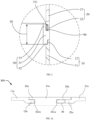
- FIGS. 1 and 2 show a sealing apparatus 100 for a robot according to the prior art.
- the sealing apparatus 100 as illustrated includes a first enclosure 10, a second enclosure 20, a seal 30, and an elastomer 40.
- the first enclosure 10 and the second enclosure 20 may be the enclosures of two adjacent arms of a robot.
- the second enclosure 20 may be rotatably connected to the first enclosure 10.
- a driving device 60 e.g., a motor or a rotary cylinder, including a stator 61 and a rotor 62 may be disposed within the two enclosures 10, 20, and one of the stator 61 and rotor 62 of the driving device may be connected to the first enclosure 10 while the other one of the stator 61 and rotor 62 of the driving device may be connected to the second enclosure 20 such that the first enclosure 10 may rotate relative to the second enclosure 20.
- the stator 61 is connected to the second enclosure 20 while the rotor 62 is connected to the first enclosure 10.
- the first enclosure 10 and the second enclosure 20 may be made of the same material, such as steel, aluminum, or an alloy. In other embodiments, the first enclosure 10 and the second enclosure 20 may be made of different materials.
- the first enclosure 10 and the second enclosure 20 may cooperatively define a gap 50 therebetween. In other words, the end of the first enclosure 10 facing the second enclosure 20 may be spaced apart from the end of the second enclosure 20 facing the first enclosure 10.
- the seal 30 may be made of plastic, silicone rubber or other materials suitable for sealing structure.
- the seal 30 may be disposed in the gap 50 and configured to seal the gap 50.
- the seal 30 and the second enclosure 20 may cooperatively define a chamber 331.
- the elastomer 40 may be disposed in the chamber 331 where the elastomer 40 is compressed by the seal 30 and the second enclosure 20.
- the elastomer 40 may be made of material with a certain elasticity such as rubber, plastic, and the like.
- the size and shape of the elastomer 40 may be in accordance with that of the chamber 311. Accordingly, the seal 30 may press against the first enclosure 10 due to an elastic force generated by the deformation of the elastomer 40.
- the gap 50 may thereby be sealed by the seal 30 and the elastomer 40.
- the end of the first enclosure 10 facing the second enclosure 20 may have a circular profile as well as the end of the second enclosure 20 facing the first enclosure 10, such that when connected together the first enclosure 10 and the second enclosure 20 may rotate smoothly.
- the seal 30 may also have an annular configuration corresponding to the first enclosure 10 and the second enclosure 20.
- the seal 30 may be directly disposed in the gap 50 between the first enclosure 10 and the second enclosure 20, and an elastomer 40 may be compressed by the seal 30 and the second enclosure 20 such that the gap 50 may be sealed by the seal 30 and the elastomer 40.
- the above-discussed example may therefore achieve adequate sealing between the first enclosure 10 and the second enclosure 20 of the robot with a simpler structure than conventional designs. Therefore, the cost of the robot may be reduced.
- the first enclosure 10 includes a first body 11 and a first protrusion 12.
- the first protrusion 12 extends from the first body 11 towards the second enclosure 20.
- the second enclosure 20 includes a second body 21 and a second protrusion 22.
- the second protrusion 22 extends from the second body 21 towards the first enclosure 10.
- the first protrusion 12 (and/or the first body 11) is spaced apart from the second protrusion 22 (and/or the second body 21) such that the gap 50 is formed therebetween.
- the seal 30 includes a main body 31, a first end 32, and a second end 33.
- the first end 32 of the seal 30 protrudes from the main body 31 towards the first enclosure 10, and matches the shape of the first protrusion 12.
- the second end 33 of the seal 30 protrudes from the main body 31 towards the second enclosure 20.
- the second end 33 of the seal 30 and the second protrusion 22 cooperatively define the chamber 331 mentioned above.
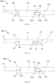
- FIGS. 3a-3d show several exemplary sealing apparatuses 300, 302, 304, 306.
- the first end 32a, 32b of the seal 30 may defines a first annular recess 321a, 321b, such as in the sealing apparatuses 300, 302 of FIGS. 3a and 3b .
- first annular recess 321a, 321b may extend along a circumference of the seal 30.
- first protrusion 12a, 12b may extend along a circumference of the first enclosure 10. All or part of the first protrusion 12a, 12b may be located within the first annular recess 321a, 321b.
- the first end 32a, 32b of the seal 30 may abut the first body 11a, 11b of the first enclosure 10. In other words, once sealed there may be no gap or opening between the first end 32a, 32b of the seal 30 and the first body 11a, 11b of the first enclosure 10, and water or dust may be prevented from entering an inner side of the first enclosure 10 and the seal 30.
- the first end 32c, 32d and the main body 31c, 31d of the seal 30 may both have annular cylindrical configurations, such as in the sealing apparatuses 304, 306 of FIGS. 3c and 3d .
- the thickness of the first end 32c, 32d may be less than the thickness of the main body 31c, 31d, and may thereby form a first flanged surface 322c, 322d at an outer side of the seal 30.
- the first protrusion 12c, 12d of the first enclosure 10 may abut the first flanged surface 322c, 322d such that dust or water is prevented from entering the inner side of the sealing apparatus 304, 306.
- the second end 33a, 33c of the seal 30 defines a second annular recess 331a, 331c, as with the sealing apparatuses 300, 304 shown in FIGS. 3a , 3c .
- the second annular recess 331a, 331c may extend along a circumference of the seal 30.
- the second protrusion 22a, 22c extends along a circumference of the second enclosure 20. All or part of the second protrusion 22a, 22c is located within the second annular recess 331a, 331c.
- the second end 33a, 33c of the seal 30 abuts the second body 21a, 21c of the second enclosure 20 while the second protrusion 22a, 22c is spaced apart from the bottom wall of the second annular recess 331a.
- the chamber 331 is formed between the bottom wall of the second annular recess 331a, 331c and the second protrusion 22a, 22c.
- the chamber 331 may be a portion of the second annular recess 331a, 331c which is not occupied by the second protrusion 22a, 22c. Since the elastomer 40 may be compressed in the chamber 331, water and dust may be prevented from entering the inner side of the sealing apparatus 300, 304.
- the second end 33b, 33d and the main body 31b, 31d of the seal 30 may both have an annular cylindrical configuration, as shown in the sealing apparatuses 302, 306 of FIGS. 3b and 3d .
- the thickness of the second end 33b, 33d may be less than the thickness of the main body 31b, 31d, and thereby forming a second flanged surface 332b, 332d at an outer side of the seal 30.
- the second protrusion 22b, 22d of the second enclosure 20 may be spaced apart from the second flanged surface 332b, 332d, and the chamber 331b, 331d may thereby be formed between the second protrusion 22b, 226 and the second enclosure 20. Since the elastomer 40 may be compressed in the chamber 331b, 331d, to prevent water or dust from entering the inner side of the seal 30.
- the seal 30 may be made of transparent or translucent plastic material, which does not cause a significant friction when the first enclosure 10 rotates relative to the second enclosure 20.
- the sealing apparatus may further include a lighting device 70.
- the lighting device 70 may be disposed at an inner side of the seal 30 and corresponding to the location of the seal 30. In this embodiment, the lighting device 70 is connected to the second enclosure 20. In other embodiments, the lighting device 70 may alternative be connected to the first enclosure 10.
- the lighting device 70 may include any kind of light-emitting components.
- the lighting device 70 may have an annular configuration extending along the entire circumference of the first and second enclosures 10, 20.
- the lighting device 70 may include several separated sub-lighting elements arranged along the circumference of the first and second enclosures 10, 20.
- the light-emitting surface of the lighting device may face the seal 30 such that the lighting device 70 may be utilized to illuminate the transparent or translucent seal 30, allowing the operator of the robot to easily observe the condition of the seal 30 and/or the robot.
- the sealing apparatus may further include a processor (not shown) coupled to the lighting device 70
- the robot on which the sealing apparatus is installed may include several sensors, such as vibration detectors and temperature sensors. The information collected by these sensors may be utilized to determine an operation condition of the robot.
- the processor may receive the robot condition information and instruct the lighting device 70 to change a lighting mode based on the operation condition. For example, when the robot functions normally, the processor may instruct the lighting device 70 to emit light continuously. When vibration levels of the robot are too high, the processor may instruct the lighting device 70 to flash at a certain frequency. Or when the temperature of the robot is above a pre-determined threshold, the processor may control the lighting device 70 to change its light color. It should be appreciated that the foregoing are merely exemplary lighting modes of the lighting device 70.
- the designer of the sealing apparatus or the robot may employ other lighting modes, which are also considered within the scope of the present disclosure.
- One or more of the above-discussed functions of the processor may be implemented in combination with a memory.
- the memory may store instructions which, when executed by the processor, cause the processor to implement the above-described functions.
- FIG. 5 depicts a robotic joint 500 according to an exemplary embodiment of the present disclosure.
- the robotic joint 500 includes a first enclosure 10 and a second enclosure 20 cooperatively constituting a pitch joint, sealed by a seal 30.
- the first enclosure 10 and the second enclosure 20 may cooperatively constitute a roll joint.
- the present disclosure further provides an articulated robot with a sealing apparatus as recited in any of the embodiments described above.
- the articulated robot may include one or more robotic joints 500.
- the articulated robot may include a first enclosure, a second enclosure, a driving device, a seal, and an elastomer.
- the first enclosure and the second enclosure may cooperatively define a gap therebetween.
- the driving device may be connected to the first enclosure and the second enclosure, and may be utilized to drive the first enclosure and the second enclosure to rotate relative to each other based on movement indication of the articulated robot.
- the seal may be disposed in the gap, where the seal and the second enclosure may cooperatively define a chamber.
- the elastomer may be disposed in the chamber.
- the elastomer may be compressed by the seal and the second enclosure such that the seal may cling to the first enclosure under an elastic force generated by the deformation of the elastomer.
- the gap between the first enclosure and the second enclosure may be sealed by the seal and the elastomer.
- first enclosure the second enclosure
- seal the seal
- elastomer the driving device or any other components of the articulated robot
Landscapes
- Engineering & Computer Science (AREA)
- Robotics (AREA)
- Mechanical Engineering (AREA)
- Gasket Seals (AREA)
- Manipulator (AREA)
- Sealing Devices (AREA)
Description
- The present disclosure generally relates to robotic systems and techniques, and in particular to a sealing apparatus and an articulated robot.
- Waterproof and dustproof structures are often provided to protect the internal electrical components of robots. In related art, a driving device may be incorporated into a joint section of an articulated robot to drive an arm or a wrist of the robot. A seal, e.g., an oil seal, may be set in a relatively moveable region of an output shaft of the driving device. Such seals usually have complex designs with a bulky size and high friction, which leads to a high cost of the sealing structure and the robot.
-
DE 10 2015 209547 A1 discloses a robot comprising a robot arm which has a plurality of joints connected by members that are adjustable automatically according to a robot program by drive motors coupled to the joints in order to change the configuration of the robot arm. The robot arm includes a sealing arrangement that comprises a sealing lip of a sealing strip that seals a housing shell against a hollow structural part. -
CN 104 812 536 A discloses a joint seal structure of robot that includes a fitting end portion provided on an end portion of a second member and fittingly inserted into tubular end portion of a first member. A peripheral groove is provided on an inner peripheral surface of the tubular end portion to extend over an entire periphery; and an annular seal member is accommodated into peripheral groove and in sealing contact with outer peripheral surface of fitting end portion. - Aspects of the invention are set out in the appended claims. The present disclosure provides a sealing apparatus and a robot including the sealing apparatus in order to address the above-identified problems.
- According to the present disclosure, the seal may be directly disposed in the gap between the first enclosure and the second enclosure, and an elastomer may be compressed by the seal and the second enclosure such that the gap may be sealed by the seal and the elastomer. Thus, the implementation of the present disclosure may achieve the sealing between the first enclosure and the second enclosure of the robot with a simple structure. Therefore, the cost and the assembling effort of the robot may be reduced.
- The features and advantages described herein are not all-inclusive and, in particular, many additional features and advantages will be apparent to one of ordinary skill in the art in view of the figures and description. Moreover, it should be noted that the language used in the specification has been principally selected for readability and instructional purposes, and not to limit the scope of the disclosed subject matter.
- To more clearly explain the technical solutions in the embodiments of the present disclosure, the drawings used in the description of the embodiments will be briefly described below. The drawings in the following description are merely exemplary embodiments of the present disclosure. For those of ordinary skill in the art, other drawings may also be obtained based on these drawings without any creative work.
-
FIG. 1 illustrates a section view of a sealing apparatus for a robot according to the prior art. -
FIG. 2 illustrates an enlarged view of zone II of the exemplary depiction depicted inFIG. 1 . -
FIGS. 3a and3c illustrate configurations of the sealing apparatus according to exemplary embodiments of the present invention. -
FIGS. 3b and 3d illustrate a sealing apparatus according to the prior art. -
FIG. 4 illustrates a section view of a sealing apparatus for a robot according to the prior art. -
FIG. 5 shows a perspective view of an articulated robot according to an exemplary embodiment of the present disclosure. - The disclosure will now be described in detail with reference to the accompanying drawings and examples. The described embodiments are only a part of the embodiments of the present disclosure, not all of the embodiments. The scope of the invention is defined by the appended claims.
-
FIGS. 1 and2 show a sealingapparatus 100 for a robot according to the prior art. Thesealing apparatus 100 as illustrated includes afirst enclosure 10, asecond enclosure 20, aseal 30, and anelastomer 40. - The
first enclosure 10 and thesecond enclosure 20 may be the enclosures of two adjacent arms of a robot. Thesecond enclosure 20 may be rotatably connected to thefirst enclosure 10. Specifically, adriving device 60, e.g., a motor or a rotary cylinder, including astator 61 and arotor 62 may be disposed within the twoenclosures stator 61 androtor 62 of the driving device may be connected to thefirst enclosure 10 while the other one of thestator 61 androtor 62 of the driving device may be connected to thesecond enclosure 20 such that thefirst enclosure 10 may rotate relative to thesecond enclosure 20. For example, in the embodiment ofFIG. 1 , thestator 61 is connected to thesecond enclosure 20 while therotor 62 is connected to thefirst enclosure 10. - The
first enclosure 10 and thesecond enclosure 20 may be made of the same material, such as steel, aluminum, or an alloy. In other embodiments, thefirst enclosure 10 and thesecond enclosure 20 may be made of different materials. Thefirst enclosure 10 and thesecond enclosure 20 may cooperatively define agap 50 therebetween. In other words, the end of thefirst enclosure 10 facing thesecond enclosure 20 may be spaced apart from the end of thesecond enclosure 20 facing thefirst enclosure 10. - In certain embodiments, the
seal 30 may be made of plastic, silicone rubber or other materials suitable for sealing structure. Theseal 30 may be disposed in thegap 50 and configured to seal thegap 50. Specifically, theseal 30 and thesecond enclosure 20 may cooperatively define achamber 331. Theelastomer 40 may be disposed in thechamber 331 where theelastomer 40 is compressed by theseal 30 and thesecond enclosure 20. Theelastomer 40 may be made of material with a certain elasticity such as rubber, plastic, and the like. The size and shape of theelastomer 40 may be in accordance with that of the chamber 311. Accordingly, theseal 30 may press against thefirst enclosure 10 due to an elastic force generated by the deformation of theelastomer 40. Thegap 50 may thereby be sealed by theseal 30 and theelastomer 40. - Optionally, the end of the
first enclosure 10 facing thesecond enclosure 20 may have a circular profile as well as the end of thesecond enclosure 20 facing thefirst enclosure 10, such that when connected together thefirst enclosure 10 and thesecond enclosure 20 may rotate smoothly. In this circumstance, theseal 30 may also have an annular configuration corresponding to thefirst enclosure 10 and thesecond enclosure 20. - The
seal 30 may be directly disposed in thegap 50 between thefirst enclosure 10 and thesecond enclosure 20, and anelastomer 40 may be compressed by theseal 30 and thesecond enclosure 20 such that thegap 50 may be sealed by theseal 30 and theelastomer 40. The above-discussed example may therefore achieve adequate sealing between thefirst enclosure 10 and thesecond enclosure 20 of the robot with a simpler structure than conventional designs. Therefore, the cost of the robot may be reduced. - According to the invention, the
first enclosure 10 includes a first body 11 and afirst protrusion 12. Thefirst protrusion 12 extends from the first body 11 towards thesecond enclosure 20. Similarly, thesecond enclosure 20 includes asecond body 21 and asecond protrusion 22. Thesecond protrusion 22 extends from thesecond body 21 towards thefirst enclosure 10. The first protrusion 12 (and/or the first body 11) is spaced apart from the second protrusion 22 (and/or the second body 21) such that thegap 50 is formed therebetween. According to the invention, theseal 30 includes a main body 31, afirst end 32, and a second end 33. Thefirst end 32 of theseal 30 protrudes from the main body 31 towards thefirst enclosure 10, and matches the shape of thefirst protrusion 12. The second end 33 of theseal 30 protrudes from the main body 31 towards thesecond enclosure 20. The second end 33 of theseal 30 and thesecond protrusion 22 cooperatively define thechamber 331 mentioned above. - Referring to
FIGS. 3a-3d , thefirst enclosure 10, thesecond enclosure 20, theseal 30, and theelastomer 40 may have different configurations.FIGS. 3a-3d show severalexemplary sealing apparatuses - In some embodiments, the
first end seal 30 may defines a firstannular recess apparatuses FIGS. 3a and3b . Although only an exemplary section view is shown inFIGS. 3a and3b , those skilled in the art should understand that the firstannular recess seal 30. Similarly, thefirst protrusion first enclosure 10. All or part of thefirst protrusion annular recess first end seal 30 may abut thefirst body first enclosure 10. In other words, once sealed there may be no gap or opening between thefirst end seal 30 and thefirst body first enclosure 10, and water or dust may be prevented from entering an inner side of thefirst enclosure 10 and theseal 30. - In other embodiments, the
first end main body seal 30 may both have annular cylindrical configurations, such as in the sealingapparatuses FIGS. 3c and 3d . In such implementations, the thickness of thefirst end main body flanged surface seal 30. Thefirst protrusion first enclosure 10 may abut the firstflanged surface sealing apparatus - According to the invention, the
second end seal 30 defines a secondannular recess apparatuses FIGS. 3a ,3c . Although only an exemplary section view is shown inFIGS. 3a ,3c , one skilled in the art should understand that the secondannular recess seal 30. Similarly, thesecond protrusion second enclosure 20. All or part of thesecond protrusion annular recess second end seal 30 abuts thesecond body second enclosure 20 while thesecond protrusion annular recess 331a. Thus, thechamber 331 is formed between the bottom wall of the secondannular recess second protrusion chamber 331 may be a portion of the secondannular recess second protrusion elastomer 40 may be compressed in thechamber 331, water and dust may be prevented from entering the inner side of thesealing apparatus - In other embodiments, the
second end main body seal 30 may both have an annular cylindrical configuration, as shown in the sealingapparatuses FIGS. 3b and 3d . In such embodiments, the thickness of thesecond end main body flanged surface 332b, 332d at an outer side of theseal 30. Thesecond protrusion second enclosure 20 may be spaced apart from the secondflanged surface 332b, 332d, and thechamber second protrusion 22b, 226 and thesecond enclosure 20. Since theelastomer 40 may be compressed in thechamber seal 30. - In some embodiments, the
seal 30 may be made of transparent or translucent plastic material, which does not cause a significant friction when thefirst enclosure 10 rotates relative to thesecond enclosure 20. In certain implementations, as shown inFIG. 4 , the sealing apparatus may further include alighting device 70. Thelighting device 70 may be disposed at an inner side of theseal 30 and corresponding to the location of theseal 30. In this embodiment, thelighting device 70 is connected to thesecond enclosure 20. In other embodiments, thelighting device 70 may alternative be connected to thefirst enclosure 10. Thelighting device 70 may include any kind of light-emitting components. Thelighting device 70 may have an annular configuration extending along the entire circumference of the first andsecond enclosures lighting device 70 may include several separated sub-lighting elements arranged along the circumference of the first andsecond enclosures seal 30 such that thelighting device 70 may be utilized to illuminate the transparent ortranslucent seal 30, allowing the operator of the robot to easily observe the condition of theseal 30 and/or the robot. - In some embodiments, the sealing apparatus may further include a processor (not shown) coupled to the
lighting device 70 The robot on which the sealing apparatus is installed may include several sensors, such as vibration detectors and temperature sensors. The information collected by these sensors may be utilized to determine an operation condition of the robot. The processor may receive the robot condition information and instruct thelighting device 70 to change a lighting mode based on the operation condition. For example, when the robot functions normally, the processor may instruct thelighting device 70 to emit light continuously. When vibration levels of the robot are too high, the processor may instruct thelighting device 70 to flash at a certain frequency. Or when the temperature of the robot is above a pre-determined threshold, the processor may control thelighting device 70 to change its light color. It should be appreciated that the foregoing are merely exemplary lighting modes of thelighting device 70. In practice, the designer of the sealing apparatus or the robot may employ other lighting modes, which are also considered within the scope of the present disclosure. One or more of the above-discussed functions of the processor may be implemented in combination with a memory. For example, the memory may store instructions which, when executed by the processor, cause the processor to implement the above-described functions. -
FIG. 5 depicts a robotic joint 500 according to an exemplary embodiment of the present disclosure. The robotic joint 500 includes afirst enclosure 10 and asecond enclosure 20 cooperatively constituting a pitch joint, sealed by aseal 30. In other implementations, thefirst enclosure 10 and thesecond enclosure 20 may cooperatively constitute a roll joint. - The present disclosure further provides an articulated robot with a sealing apparatus as recited in any of the embodiments described above. The articulated robot may include one or more
robotic joints 500. For example, the articulated robot may include a first enclosure, a second enclosure, a driving device, a seal, and an elastomer. The first enclosure and the second enclosure may cooperatively define a gap therebetween. The driving device may be connected to the first enclosure and the second enclosure, and may be utilized to drive the first enclosure and the second enclosure to rotate relative to each other based on movement indication of the articulated robot. The seal may be disposed in the gap, where the seal and the second enclosure may cooperatively define a chamber. The elastomer may be disposed in the chamber. The elastomer may be compressed by the seal and the second enclosure such that the seal may cling to the first enclosure under an elastic force generated by the deformation of the elastomer. Thus, the gap between the first enclosure and the second enclosure may be sealed by the seal and the elastomer. - The detailed structure of the first enclosure, the second enclosure, the seal, the elastomer, the driving device or any other components of the articulated robot may be similar to the embodiments described above.
- The foregoing are merely exemplary embodiments of the present disclosure, and is not intended to limit the scope of the invention as defined by the appended claims.
Claims (5)
- A sealing apparatus (100) for a robot, the sealing apparatus comprising:a first enclosure (10);a second enclosure (20) rotatably connected to the first enclosure (10), wherein the first enclosure (10) and the second enclosure (20) cooperatively define a gap (50) between the first enclosure (10) and the second enclosure (20);a seal (30) disposed in the gap (50), wherein the seal (30) and the second enclosure (20) cooperatively define a chamber (331); andan elastomer (40) disposed in the chamber (331), wherein the elastomer (40) is compressed by the seal (30) and the second enclosure (20), generating an elastic force that presses the seal (30) against the first enclosure (10), whereinthe first enclosure (10) comprises a first body (11) and a first protrusion (12) extending from the first body (11) towards the second enclosure (20),the second enclosure (20) comprises a second body (21) and a second protrusion (22), the second protrusion (22) extends from the second body (20) towards the first enclosure (10) and is spaced apart from the first protrusion (12) such that the gap (50) is formed, andthe seal (30) comprises a main body (31), a first end (32), and a second end (33), the first end (32) of the seal (30) protrudes from the main body (31) towards the first enclosure (10) and matches the first protrusion (12), the second end (33) of the seal (30) protrudes from the main body (31) towards the second enclosure (20), and the second end (33) of the seal (30) and the second protrusion (22) cooperatively define the chamber (331),characterised in that:the second end (33a, 33c) of the seal (30) defines a second annular recess (331a, 331c) extending along a circumference of the seal (30); andthe second protrusion (22a, 22c) extends along a circumference of the second enclosure (20), wherein at least a portion of the second protrusion (22a, 22c) is located within the second annular recess (331a, 331c), wherein the second end (33a, 33c) of the seal (30) abuts the second body (21a, 21c) of the second enclosure (20), and wherein the second protrusion (22a, 22c) is spaced apart from a bottom wall of the second annular recess (331a) such that the chamber (331) is formed between the bottom wall of the second annular recess (331a, 331c) and the second protrusion (22a, 22c).
- The sealing apparatus (100) of claim 1, whereinthe first end (32) of the seal (30) defines a first annular recess (321a, 321b) extending along a circumference of the seal (30), andthe first protrusion (12a, 12b) extends along a circumference of the first enclosure (10), at least a portion of the first protrusion (12a, 12b) is located within the first annular recess (321a, 321b), and the first end (32a, 32b) of the seal (30) abuts the first body (11a, 11b) of the first enclosure (10).
- The sealing apparatus (100) of claim 1, whereinthe first end (32c, 32d) and the main body (31c, 31d) of the seal (30) both have an annular cylindrical configuration, and a thickness of the first end (32c, 32d) is less than a thickness of the main body (31c, 31d) to form a first flanged surface (322c, 322d) at an outer side of the seal (30), andthe first protrusion (12c, 12d) abuts the first flanged surface (322c, 322d).
- The sealing apparatus (100) of claim 1, wherein the first enclosure (10) and the second enclosure (20) cooperatively constitute a pitch joint or a roll joint.
- An articulated robot comprising:the sealing apparatus of any one of claims 1 to 4; anda driving device connected to the first enclosure (10) and the second enclosure (20), wherein the driving device is configured to drive the first enclosure (10) and the second enclosure (20) to rotate relative to each other based on movement indication of the articulated robot.
Priority Applications (1)
| Application Number | Priority Date | Filing Date | Title |
|---|---|---|---|
| EP21181891.9A EP3912766B1 (en) | 2018-10-02 | 2019-09-24 | Sealing apparatus and articulated robot |
Applications Claiming Priority (3)
| Application Number | Priority Date | Filing Date | Title |
|---|---|---|---|
| US201862740190P | 2018-10-02 | 2018-10-02 | |
| US16/545,433 US11167433B2 (en) | 2018-10-02 | 2019-08-20 | Sealing apparatus and articulated robot |
| PCT/CN2019/107393 WO2020069653A1 (en) | 2018-10-02 | 2019-09-24 | Sealing apparatus and articulated robot |
Related Child Applications (2)
| Application Number | Title | Priority Date | Filing Date |
|---|---|---|---|
| EP21181891.9A Division EP3912766B1 (en) | 2018-10-02 | 2019-09-24 | Sealing apparatus and articulated robot |
| EP21181891.9A Division-Into EP3912766B1 (en) | 2018-10-02 | 2019-09-24 | Sealing apparatus and articulated robot |
Publications (3)
| Publication Number | Publication Date |
|---|---|
| EP3781361A1 EP3781361A1 (en) | 2021-02-24 |
| EP3781361A4 EP3781361A4 (en) | 2021-10-06 |
| EP3781361B1 true EP3781361B1 (en) | 2024-02-14 |
Family
ID=69947065
Family Applications (2)
| Application Number | Title | Priority Date | Filing Date |
|---|---|---|---|
| EP19869323.6A Active EP3781361B1 (en) | 2018-10-02 | 2019-09-24 | Sealing apparatus and articulated robot |
| EP21181891.9A Active EP3912766B1 (en) | 2018-10-02 | 2019-09-24 | Sealing apparatus and articulated robot |
Family Applications After (1)
| Application Number | Title | Priority Date | Filing Date |
|---|---|---|---|
| EP21181891.9A Active EP3912766B1 (en) | 2018-10-02 | 2019-09-24 | Sealing apparatus and articulated robot |
Country Status (4)
| Country | Link |
|---|---|
| US (1) | US11167433B2 (en) |
| EP (2) | EP3781361B1 (en) |
| CN (1) | CN110944810B (en) |
| WO (1) | WO2020069653A1 (en) |
Families Citing this family (6)
| Publication number | Priority date | Publication date | Assignee | Title |
|---|---|---|---|---|
| US11331814B2 (en) * | 2018-09-13 | 2022-05-17 | Kinova Inc. | Articulated mechanism with protective sleeve at joint |
| CN116209846B (en) * | 2020-09-10 | 2025-12-23 | Abb瑞士股份有限公司 | Sealing structure for robot joints and robot joint including the sealing structure |
| CN113696226B (en) * | 2021-08-13 | 2023-02-03 | 万勋科技(深圳)有限公司 | Mechanical arm protection method and mechanical arm |
| DE102022205077A1 (en) | 2022-05-20 | 2023-11-23 | Kuka Deutschland Gmbh | Sealing a radial gap between two links of a robot arm |
| CN115899265B (en) * | 2022-12-21 | 2026-05-05 | 上海非夕机器人科技有限公司 | Sealing devices and equipment and robots having them |
| KR102619169B1 (en) * | 2023-02-20 | 2023-12-29 | 주식회사 새비로보틱스 | Modular robot provided with waterproof structure and manufacturing method thereof |
Family Cites Families (19)
| Publication number | Priority date | Publication date | Assignee | Title |
|---|---|---|---|---|
| DE3045855A1 (en) * | 1980-12-05 | 1982-07-08 | Howaldtswerke-Deutsche Werft Ag Hamburg Und Kiel, 2300 Kiel | SEALING ARRANGEMENT FOR ROTATING SHAFTS |
| US5394766A (en) | 1992-07-21 | 1995-03-07 | The Walt Disney Company | Robotic human torso |
| JPH08330777A (en) | 1995-06-02 | 1996-12-13 | Fanuc Ltd | Panel protecting structure |
| US5979903A (en) * | 1997-12-04 | 1999-11-09 | Sanford Acquisition Company | Translucent slinger with centrifugal seal |
| JP3806312B2 (en) | 2001-04-25 | 2006-08-09 | ファナック株式会社 | Main shaft protection structure in spindle through coolant |
| US7587863B2 (en) * | 2006-08-17 | 2009-09-15 | Fike Corporation | Seal for sanitary overpressure vent structure |
| US7503790B2 (en) * | 2007-07-03 | 2009-03-17 | Rockwell Automation Technologies, Inc. | Industrial automation input output module with elastomeric sealing |
| WO2014087615A1 (en) | 2012-12-05 | 2014-06-12 | 川崎重工業株式会社 | Robot joint sealing structure |
| DE102015001504B4 (en) * | 2014-02-11 | 2025-11-13 | GIMATIC S.r.l. | Protective housing for robot grippers |
| CN204054079U (en) * | 2014-05-28 | 2014-12-31 | 赵海亮 | A kind of knuckle type industrial robot compensating cylinder |
| CN104047640B (en) * | 2014-06-10 | 2015-11-18 | 清华大学 | A kind of brush seal structure of adjustable radial gap |
| US10113644B2 (en) * | 2014-08-29 | 2018-10-30 | Parker-Hannifin Corporation | Self-lubricating and draining, contacting face, rotating shaft seal |
| DE102014226144A1 (en) * | 2014-12-16 | 2016-06-16 | Kuka Roboter Gmbh | Industrial robots and method for moving a robot arm in a clean room |
| CN105619380B (en) | 2015-01-12 | 2017-09-05 | 浙江琦星电子有限公司 | A kind of assembly method of mechanical arm |
| DE102015209547A1 (en) | 2015-05-22 | 2016-11-24 | Kuka Roboter Gmbh | Robot with a power line |
| EP3130305B1 (en) * | 2015-08-12 | 2021-01-13 | medineering GmbH | Medical holding arm |
| JP6506227B2 (en) * | 2016-08-31 | 2019-04-24 | ファナック株式会社 | Joint structure and robot |
| JP6382906B2 (en) * | 2016-10-17 | 2018-08-29 | ファナック株式会社 | Robot and indicator light installation method for robot |
| CN108582163B (en) | 2018-06-26 | 2024-08-20 | 埃夫特智能装备股份有限公司 | Robot swivel mount structure based on dustproof damp proof seals |
-
2019
- 2019-08-20 US US16/545,433 patent/US11167433B2/en active Active
- 2019-09-24 CN CN201980003206.0A patent/CN110944810B/en active Active
- 2019-09-24 EP EP19869323.6A patent/EP3781361B1/en active Active
- 2019-09-24 EP EP21181891.9A patent/EP3912766B1/en active Active
- 2019-09-24 WO PCT/CN2019/107393 patent/WO2020069653A1/en not_active Ceased
Also Published As
| Publication number | Publication date |
|---|---|
| EP3912766B1 (en) | 2024-02-28 |
| EP3912766A1 (en) | 2021-11-24 |
| CN110944810A (en) | 2020-03-31 |
| EP3781361A1 (en) | 2021-02-24 |
| EP3781361A4 (en) | 2021-10-06 |
| WO2020069653A1 (en) | 2020-04-09 |
| CN110944810B (en) | 2020-09-04 |
| US11167433B2 (en) | 2021-11-09 |
| US20200101628A1 (en) | 2020-04-02 |
Similar Documents
| Publication | Publication Date | Title |
|---|---|---|
| EP3912766B1 (en) | Sealing apparatus and articulated robot | |
| KR940701506A (en) | Compressor assembly with fixed shell | |
| EP3184864B1 (en) | Sealing structure | |
| US5431414A (en) | Seal device | |
| US20190203825A1 (en) | Actuator | |
| US8436502B2 (en) | Electric motor with sealing means | |
| US11300207B2 (en) | Seal member and robot | |
| US8534254B2 (en) | Starter device | |
| JPH11108202A (en) | Labyrinth seal | |
| EP1553336B1 (en) | Multistage oil seal for machine tool motor | |
| JP5568119B2 (en) | Electric motor with holes for hermetic testing | |
| JP4448105B2 (en) | Compressor seal structure | |
| CN211709349U (en) | Two-degree-of-freedom underwater manipulator | |
| JP2020183776A (en) | Sealing device | |
| JP7309295B2 (en) | Vertical sealing device | |
| CN221391125U (en) | Seal assembly of joint module, joint module and mechanical arm | |
| RU1786607C (en) | Automobile generator | |
| US11255439B2 (en) | Axial shaft seal ring and seal arrangement | |
| CN109245394A (en) | Sealing structure, shaft sealing device and motor | |
| JPH066691Y2 (en) | Waterproof structure of fan motor | |
| JPH0726611Y2 (en) | Sealing device | |
| JP4165315B2 (en) | Seal structure of constant velocity joint boot | |
| JPH08540Y2 (en) | Air bleeding structure for rotating equipment | |
| KR20190124586A (en) | Mechanical seal including advanced plate structure and cap structure | |
| JPH0680064U (en) | Oil seal |
Legal Events
| Date | Code | Title | Description |
|---|---|---|---|
| STAA | Information on the status of an ep patent application or granted ep patent |
Free format text: STATUS: THE INTERNATIONAL PUBLICATION HAS BEEN MADE |
|
| PUAI | Public reference made under article 153(3) epc to a published international application that has entered the european phase |
Free format text: ORIGINAL CODE: 0009012 |
|
| STAA | Information on the status of an ep patent application or granted ep patent |
Free format text: STATUS: REQUEST FOR EXAMINATION WAS MADE |
|
| 17P | Request for examination filed |
Effective date: 20201120 |
|
| AK | Designated contracting states |
Kind code of ref document: A1 Designated state(s): AL AT BE BG CH CY CZ DE DK EE ES FI FR GB GR HR HU IE IS IT LI LT LU LV MC MK MT NL NO PL PT RO RS SE SI SK SM TR |
|
| AX | Request for extension of the european patent |
Extension state: BA ME |
|
| RIC1 | Information provided on ipc code assigned before grant |
Ipc: B25J 9/00 20060101AFI20210521BHEP Ipc: B25J 17/00 20060101ALI20210521BHEP Ipc: B25J 19/00 20060101ALI20210521BHEP |
|
| DAV | Request for validation of the european patent (deleted) | ||
| DAX | Request for extension of the european patent (deleted) | ||
| A4 | Supplementary search report drawn up and despatched |
Effective date: 20210903 |
|
| RIC1 | Information provided on ipc code assigned before grant |
Ipc: B25J 19/00 20060101ALI20210830BHEP Ipc: B25J 17/00 20060101ALI20210830BHEP Ipc: B25J 9/00 20060101AFI20210830BHEP |
|
| GRAP | Despatch of communication of intention to grant a patent |
Free format text: ORIGINAL CODE: EPIDOSNIGR1 |
|
| STAA | Information on the status of an ep patent application or granted ep patent |
Free format text: STATUS: GRANT OF PATENT IS INTENDED |
|
| INTG | Intention to grant announced |
Effective date: 20230907 |
|
| GRAS | Grant fee paid |
Free format text: ORIGINAL CODE: EPIDOSNIGR3 |
|
| GRAA | (expected) grant |
Free format text: ORIGINAL CODE: 0009210 |
|
| STAA | Information on the status of an ep patent application or granted ep patent |
Free format text: STATUS: THE PATENT HAS BEEN GRANTED |
|
| AK | Designated contracting states |
Kind code of ref document: B1 Designated state(s): AL AT BE BG CH CY CZ DE DK EE ES FI FR GB GR HR HU IE IS IT LI LT LU LV MC MK MT NL NO PL PT RO RS SE SI SK SM TR |
|
| REG | Reference to a national code |
Ref country code: GB Ref legal event code: FG4D |
|
| REG | Reference to a national code |
Ref country code: CH Ref legal event code: EP |
|
| REG | Reference to a national code |
Ref country code: DE Ref legal event code: R096 Ref document number: 602019046690 Country of ref document: DE |
|
| P01 | Opt-out of the competence of the unified patent court (upc) registered |
Effective date: 20240207 |
|
| REG | Reference to a national code |
Ref country code: IE Ref legal event code: FG4D |
|
| REG | Reference to a national code |
Ref country code: LT Ref legal event code: MG9D |
|
| REG | Reference to a national code |
Ref country code: NL Ref legal event code: MP Effective date: 20240214 |
|
| PG25 | Lapsed in a contracting state [announced via postgrant information from national office to epo] |
Ref country code: IS Free format text: LAPSE BECAUSE OF FAILURE TO SUBMIT A TRANSLATION OF THE DESCRIPTION OR TO PAY THE FEE WITHIN THE PRESCRIBED TIME-LIMIT Effective date: 20240614 |
|
| PG25 | Lapsed in a contracting state [announced via postgrant information from national office to epo] |
Ref country code: LT Free format text: LAPSE BECAUSE OF FAILURE TO SUBMIT A TRANSLATION OF THE DESCRIPTION OR TO PAY THE FEE WITHIN THE PRESCRIBED TIME-LIMIT Effective date: 20240214 |
|
| PG25 | Lapsed in a contracting state [announced via postgrant information from national office to epo] |
Ref country code: GR Free format text: LAPSE BECAUSE OF FAILURE TO SUBMIT A TRANSLATION OF THE DESCRIPTION OR TO PAY THE FEE WITHIN THE PRESCRIBED TIME-LIMIT Effective date: 20240515 |
|
| REG | Reference to a national code |
Ref country code: AT Ref legal event code: MK05 Ref document number: 1656650 Country of ref document: AT Kind code of ref document: T Effective date: 20240214 |
|
| PG25 | Lapsed in a contracting state [announced via postgrant information from national office to epo] |
Ref country code: HR Free format text: LAPSE BECAUSE OF FAILURE TO SUBMIT A TRANSLATION OF THE DESCRIPTION OR TO PAY THE FEE WITHIN THE PRESCRIBED TIME-LIMIT Effective date: 20240214 Ref country code: RS Free format text: LAPSE BECAUSE OF FAILURE TO SUBMIT A TRANSLATION OF THE DESCRIPTION OR TO PAY THE FEE WITHIN THE PRESCRIBED TIME-LIMIT Effective date: 20240514 Ref country code: NL Free format text: LAPSE BECAUSE OF FAILURE TO SUBMIT A TRANSLATION OF THE DESCRIPTION OR TO PAY THE FEE WITHIN THE PRESCRIBED TIME-LIMIT Effective date: 20240214 |
|
| PG25 | Lapsed in a contracting state [announced via postgrant information from national office to epo] |
Ref country code: ES Free format text: LAPSE BECAUSE OF FAILURE TO SUBMIT A TRANSLATION OF THE DESCRIPTION OR TO PAY THE FEE WITHIN THE PRESCRIBED TIME-LIMIT Effective date: 20240214 |
|
| PG25 | Lapsed in a contracting state [announced via postgrant information from national office to epo] |
Ref country code: AT Free format text: LAPSE BECAUSE OF FAILURE TO SUBMIT A TRANSLATION OF THE DESCRIPTION OR TO PAY THE FEE WITHIN THE PRESCRIBED TIME-LIMIT Effective date: 20240214 |
|
| PG25 | Lapsed in a contracting state [announced via postgrant information from national office to epo] |
Ref country code: RS Free format text: LAPSE BECAUSE OF FAILURE TO SUBMIT A TRANSLATION OF THE DESCRIPTION OR TO PAY THE FEE WITHIN THE PRESCRIBED TIME-LIMIT Effective date: 20240514 Ref country code: NO Free format text: LAPSE BECAUSE OF FAILURE TO SUBMIT A TRANSLATION OF THE DESCRIPTION OR TO PAY THE FEE WITHIN THE PRESCRIBED TIME-LIMIT Effective date: 20240514 Ref country code: NL Free format text: LAPSE BECAUSE OF FAILURE TO SUBMIT A TRANSLATION OF THE DESCRIPTION OR TO PAY THE FEE WITHIN THE PRESCRIBED TIME-LIMIT Effective date: 20240214 Ref country code: LT Free format text: LAPSE BECAUSE OF FAILURE TO SUBMIT A TRANSLATION OF THE DESCRIPTION OR TO PAY THE FEE WITHIN THE PRESCRIBED TIME-LIMIT Effective date: 20240214 Ref country code: IS Free format text: LAPSE BECAUSE OF FAILURE TO SUBMIT A TRANSLATION OF THE DESCRIPTION OR TO PAY THE FEE WITHIN THE PRESCRIBED TIME-LIMIT Effective date: 20240614 Ref country code: HR Free format text: LAPSE BECAUSE OF FAILURE TO SUBMIT A TRANSLATION OF THE DESCRIPTION OR TO PAY THE FEE WITHIN THE PRESCRIBED TIME-LIMIT Effective date: 20240214 Ref country code: GR Free format text: LAPSE BECAUSE OF FAILURE TO SUBMIT A TRANSLATION OF THE DESCRIPTION OR TO PAY THE FEE WITHIN THE PRESCRIBED TIME-LIMIT Effective date: 20240515 Ref country code: FI Free format text: LAPSE BECAUSE OF FAILURE TO SUBMIT A TRANSLATION OF THE DESCRIPTION OR TO PAY THE FEE WITHIN THE PRESCRIBED TIME-LIMIT Effective date: 20240214 Ref country code: ES Free format text: LAPSE BECAUSE OF FAILURE TO SUBMIT A TRANSLATION OF THE DESCRIPTION OR TO PAY THE FEE WITHIN THE PRESCRIBED TIME-LIMIT Effective date: 20240214 Ref country code: BG Free format text: LAPSE BECAUSE OF FAILURE TO SUBMIT A TRANSLATION OF THE DESCRIPTION OR TO PAY THE FEE WITHIN THE PRESCRIBED TIME-LIMIT Effective date: 20240214 Ref country code: AT Free format text: LAPSE BECAUSE OF FAILURE TO SUBMIT A TRANSLATION OF THE DESCRIPTION OR TO PAY THE FEE WITHIN THE PRESCRIBED TIME-LIMIT Effective date: 20240214 |
|
| PG25 | Lapsed in a contracting state [announced via postgrant information from national office to epo] |
Ref country code: PT Free format text: LAPSE BECAUSE OF FAILURE TO SUBMIT A TRANSLATION OF THE DESCRIPTION OR TO PAY THE FEE WITHIN THE PRESCRIBED TIME-LIMIT Effective date: 20240614 Ref country code: PL Free format text: LAPSE BECAUSE OF FAILURE TO SUBMIT A TRANSLATION OF THE DESCRIPTION OR TO PAY THE FEE WITHIN THE PRESCRIBED TIME-LIMIT Effective date: 20240214 |
|
| PG25 | Lapsed in a contracting state [announced via postgrant information from national office to epo] |
Ref country code: SE Free format text: LAPSE BECAUSE OF FAILURE TO SUBMIT A TRANSLATION OF THE DESCRIPTION OR TO PAY THE FEE WITHIN THE PRESCRIBED TIME-LIMIT Effective date: 20240214 Ref country code: PT Free format text: LAPSE BECAUSE OF FAILURE TO SUBMIT A TRANSLATION OF THE DESCRIPTION OR TO PAY THE FEE WITHIN THE PRESCRIBED TIME-LIMIT Effective date: 20240614 Ref country code: PL Free format text: LAPSE BECAUSE OF FAILURE TO SUBMIT A TRANSLATION OF THE DESCRIPTION OR TO PAY THE FEE WITHIN THE PRESCRIBED TIME-LIMIT Effective date: 20240214 Ref country code: LV Free format text: LAPSE BECAUSE OF FAILURE TO SUBMIT A TRANSLATION OF THE DESCRIPTION OR TO PAY THE FEE WITHIN THE PRESCRIBED TIME-LIMIT Effective date: 20240214 |
|
| PG25 | Lapsed in a contracting state [announced via postgrant information from national office to epo] |
Ref country code: DK Free format text: LAPSE BECAUSE OF FAILURE TO SUBMIT A TRANSLATION OF THE DESCRIPTION OR TO PAY THE FEE WITHIN THE PRESCRIBED TIME-LIMIT Effective date: 20240214 |
|
| PG25 | Lapsed in a contracting state [announced via postgrant information from national office to epo] |
Ref country code: SM Free format text: LAPSE BECAUSE OF FAILURE TO SUBMIT A TRANSLATION OF THE DESCRIPTION OR TO PAY THE FEE WITHIN THE PRESCRIBED TIME-LIMIT Effective date: 20240214 |
|
| PG25 | Lapsed in a contracting state [announced via postgrant information from national office to epo] |
Ref country code: EE Free format text: LAPSE BECAUSE OF FAILURE TO SUBMIT A TRANSLATION OF THE DESCRIPTION OR TO PAY THE FEE WITHIN THE PRESCRIBED TIME-LIMIT Effective date: 20240214 Ref country code: CZ Free format text: LAPSE BECAUSE OF FAILURE TO SUBMIT A TRANSLATION OF THE DESCRIPTION OR TO PAY THE FEE WITHIN THE PRESCRIBED TIME-LIMIT Effective date: 20240214 |
|
| PG25 | Lapsed in a contracting state [announced via postgrant information from national office to epo] |
Ref country code: SK Free format text: LAPSE BECAUSE OF FAILURE TO SUBMIT A TRANSLATION OF THE DESCRIPTION OR TO PAY THE FEE WITHIN THE PRESCRIBED TIME-LIMIT Effective date: 20240214 |
|
| PG25 | Lapsed in a contracting state [announced via postgrant information from national office to epo] |
Ref country code: SM Free format text: LAPSE BECAUSE OF FAILURE TO SUBMIT A TRANSLATION OF THE DESCRIPTION OR TO PAY THE FEE WITHIN THE PRESCRIBED TIME-LIMIT Effective date: 20240214 Ref country code: SK Free format text: LAPSE BECAUSE OF FAILURE TO SUBMIT A TRANSLATION OF THE DESCRIPTION OR TO PAY THE FEE WITHIN THE PRESCRIBED TIME-LIMIT Effective date: 20240214 Ref country code: RO Free format text: LAPSE BECAUSE OF FAILURE TO SUBMIT A TRANSLATION OF THE DESCRIPTION OR TO PAY THE FEE WITHIN THE PRESCRIBED TIME-LIMIT Effective date: 20240214 Ref country code: EE Free format text: LAPSE BECAUSE OF FAILURE TO SUBMIT A TRANSLATION OF THE DESCRIPTION OR TO PAY THE FEE WITHIN THE PRESCRIBED TIME-LIMIT Effective date: 20240214 Ref country code: DK Free format text: LAPSE BECAUSE OF FAILURE TO SUBMIT A TRANSLATION OF THE DESCRIPTION OR TO PAY THE FEE WITHIN THE PRESCRIBED TIME-LIMIT Effective date: 20240214 Ref country code: CZ Free format text: LAPSE BECAUSE OF FAILURE TO SUBMIT A TRANSLATION OF THE DESCRIPTION OR TO PAY THE FEE WITHIN THE PRESCRIBED TIME-LIMIT Effective date: 20240214 |
|
| REG | Reference to a national code |
Ref country code: DE Ref legal event code: R097 Ref document number: 602019046690 Country of ref document: DE |
|
| PLBE | No opposition filed within time limit |
Free format text: ORIGINAL CODE: 0009261 |
|
| STAA | Information on the status of an ep patent application or granted ep patent |
Free format text: STATUS: NO OPPOSITION FILED WITHIN TIME LIMIT |
|
| 26N | No opposition filed |
Effective date: 20241115 |
|
| PG25 | Lapsed in a contracting state [announced via postgrant information from national office to epo] |
Ref country code: SI Free format text: LAPSE BECAUSE OF FAILURE TO SUBMIT A TRANSLATION OF THE DESCRIPTION OR TO PAY THE FEE WITHIN THE PRESCRIBED TIME-LIMIT Effective date: 20240214 Ref country code: MC Free format text: LAPSE BECAUSE OF FAILURE TO SUBMIT A TRANSLATION OF THE DESCRIPTION OR TO PAY THE FEE WITHIN THE PRESCRIBED TIME-LIMIT Effective date: 20240214 |
|
| REG | Reference to a national code |
Ref country code: CH Ref legal event code: PL |
|
| PG25 | Lapsed in a contracting state [announced via postgrant information from national office to epo] |
Ref country code: LU Free format text: LAPSE BECAUSE OF NON-PAYMENT OF DUE FEES Effective date: 20240924 |
|
| REG | Reference to a national code |
Ref country code: BE Ref legal event code: MM Effective date: 20240930 |
|
| PG25 | Lapsed in a contracting state [announced via postgrant information from national office to epo] |
Ref country code: BE Free format text: LAPSE BECAUSE OF NON-PAYMENT OF DUE FEES Effective date: 20240930 |
|
| PG25 | Lapsed in a contracting state [announced via postgrant information from national office to epo] |
Ref country code: CH Free format text: LAPSE BECAUSE OF NON-PAYMENT OF DUE FEES Effective date: 20240930 |
|
| PG25 | Lapsed in a contracting state [announced via postgrant information from national office to epo] |
Ref country code: IE Free format text: LAPSE BECAUSE OF NON-PAYMENT OF DUE FEES Effective date: 20240924 |
|
| PGFP | Annual fee paid to national office [announced via postgrant information from national office to epo] |
Ref country code: DE Payment date: 20250919 Year of fee payment: 7 |
|
| PGFP | Annual fee paid to national office [announced via postgrant information from national office to epo] |
Ref country code: GB Payment date: 20250825 Year of fee payment: 7 |
|
| PGFP | Annual fee paid to national office [announced via postgrant information from national office to epo] |
Ref country code: FR Payment date: 20250820 Year of fee payment: 7 |
|
| PGFP | Annual fee paid to national office [announced via postgrant information from national office to epo] |
Ref country code: IT Payment date: 20250930 Year of fee payment: 7 |
|
| PG25 | Lapsed in a contracting state [announced via postgrant information from national office to epo] |
Ref country code: CY Free format text: LAPSE BECAUSE OF FAILURE TO SUBMIT A TRANSLATION OF THE DESCRIPTION OR TO PAY THE FEE WITHIN THE PRESCRIBED TIME-LIMIT; INVALID AB INITIO Effective date: 20190924 |
|
| PG25 | Lapsed in a contracting state [announced via postgrant information from national office to epo] |
Ref country code: HU Free format text: LAPSE BECAUSE OF FAILURE TO SUBMIT A TRANSLATION OF THE DESCRIPTION OR TO PAY THE FEE WITHIN THE PRESCRIBED TIME-LIMIT; INVALID AB INITIO Effective date: 20190924 |