JP2020183776A - Sealing device - Google Patents
Sealing device Download PDFInfo
- Publication number
- JP2020183776A JP2020183776A JP2019087419A JP2019087419A JP2020183776A JP 2020183776 A JP2020183776 A JP 2020183776A JP 2019087419 A JP2019087419 A JP 2019087419A JP 2019087419 A JP2019087419 A JP 2019087419A JP 2020183776 A JP2020183776 A JP 2020183776A
- Authority
- JP
- Japan
- Prior art keywords
- seal
- lip
- sealing device
- seal lip
- cylindrical portion
- Prior art date
- Legal status (The legal status is an assumption and is not a legal conclusion. Google has not performed a legal analysis and makes no representation as to the accuracy of the status listed.)
- Granted
Links
Images


Landscapes
- Sealing With Elastic Sealing Lips (AREA)
- Sealing Devices (AREA)
Abstract
Description
本発明は、密封装置に関する。 The present invention relates to a sealing device.
関節型ロボットのリンク(例えばアーム)は、直接モーターで回転させることもできるが、モーターから歯車減速機を介して回転させることもできる。関節型ロボットのリンクを駆動するための歯車減速機に使用されるオイルシールが知られている(特許文献1)。このオイルシールは、ケースに配置された回転するシャフトとケースの間の隙間を封止する。 The link (for example, arm) of the articulated robot can be rotated directly by a motor, but can also be rotated from the motor via a gear reducer. An oil seal used in a gear reducer for driving a link of an articulated robot is known (Patent Document 1). This oil seal seals the gap between the rotating shaft located on the case and the case.
この種のオイルシールについては、リップの摩耗が小さく、回転体に与えるトルクが小さいことが望ましい。 For this type of oil seal, it is desirable that the lip wear is small and the torque applied to the rotating body is small.
そこで、本発明は、リップの摩耗が小さく、回転体に与えるトルクが小さい密封装置を提供する。 Therefore, the present invention provides a sealing device in which the wear of the lip is small and the torque applied to the rotating body is small.
本発明のある態様に係る密封装置は、ハウジングと、前記ハウジングに設けられた孔内に配置された回転体との間の隙間を封止し、前記ハウジングの内部空間と大気側とを隔てる密封装置であって、前記ハウジングに取り付けられる取付け円筒部と、前記取付け円筒部より径方向内側に配置されたシール円筒部と、前記取付け円筒部の大気側の端部と前記シール円筒部の大気側の端部を径方向において連結する連結円環部と、前記シール円筒部の内周面から突出し、前記回転体の外周面に摺動可能に接触させられる主シールリップと、前記シール円筒部の内周面から突出し、前記主シールリップよりも大気側に配置されており、前記主シールリップよりも内径が大きい副シールリップとを有する。前記副シールリップは、圧力が与えられないときに、前記回転体の外周面に接触せず、前記シール円筒部に外側から圧力が与えられるときに、前記回転体の外周面に摺動可能に接触させられる。前記シール円筒部、前記主シールリップおよび前記副シールリップは、弾性材料のみから形成されている。前記取付け円筒部および前記連結円環部は、前記弾性材料と剛性材料から形成されている。前記シール円筒部の大気側の端部の最小厚さは、密封装置の軸線方向における前記連結円環部から前記主シールリップのリップエッジまでの長さの1/2以下である。 The sealing device according to an aspect of the present invention seals a gap between a housing and a rotating body arranged in a hole provided in the housing, and seals the internal space of the housing and the atmosphere side. A device, which is a mounting cylindrical portion mounted on the housing, a sealed cylindrical portion arranged radially inside the mounting cylindrical portion, an end portion of the mounting cylindrical portion on the atmospheric side, and an atmospheric side of the sealed cylindrical portion. A connecting ring portion that connects the ends of the seal cylinder portion in the radial direction, a main seal lip that protrudes from the inner peripheral surface of the seal cylinder portion and is slidably contacted with the outer peripheral surface of the rotating body, and the seal cylinder portion. It has a sub-seal lip that protrudes from the inner peripheral surface, is arranged on the atmosphere side of the main seal lip, and has an inner diameter larger than that of the main seal lip. The sub-seal lip does not come into contact with the outer peripheral surface of the rotating body when no pressure is applied, and can slide on the outer peripheral surface of the rotating body when pressure is applied to the seal cylindrical portion from the outside. Be brought into contact. The seal cylindrical portion, the main seal lip and the sub seal lip are formed only from an elastic material. The mounting cylindrical portion and the connecting annular portion are formed of the elastic material and the rigid material. The minimum thickness of the end portion of the seal cylinder portion on the atmosphere side is ½ or less of the length from the connecting annular portion to the lip edge of the main seal lip in the axial direction of the sealing device.
この態様においては、副シールリップは、圧力が与えられないときに、回転体の外周面に接触しないが、シール円筒部に外側から圧力が与えられるときに、回転体の外周面に摺動可能に接触させられ、常に回転体の外周面に摺動可能に接触させられる主シールリップが回転体に与える緊縛力の増加を抑制する。したがって、主シールリップの摩耗が低減されるとともに、回転体に与えられるトルクの増加が抑制される。連結円環部は弾性材料と剛性材料から形成されており、高い剛性を有するが、連結円環部に支持されたシール円筒部は弾性材料のみから形成され、低い剛性を有しており、シール円筒部の大気側の端部の厚さは小さい。したがって、シール円筒部に外側から圧力が与えられるときに、シール円筒部は、副シールリップとともに径方向内側に変形しやすく、回転体の外周面に摺動可能に接触させられやすい。このため、主シールリップが回転体に与える緊縛力の増加を効果的に抑制することができる。 In this embodiment, the secondary seal lip does not contact the outer peripheral surface of the rotating body when no pressure is applied, but can slide on the outer peripheral surface of the rotating body when pressure is applied to the seal cylinder portion from the outside. The main seal lip, which is brought into contact with the rotating body and is always slidably contacted with the outer peripheral surface of the rotating body, suppresses an increase in the binding force applied to the rotating body. Therefore, the wear of the main seal lip is reduced, and the increase in torque applied to the rotating body is suppressed. The connecting ring portion is formed of an elastic material and a rigid material and has high rigidity, but the seal cylindrical portion supported by the connecting ring portion is formed only of the elastic material and has low rigidity and has a seal. The thickness of the end of the cylinder on the atmosphere side is small. Therefore, when pressure is applied to the seal cylindrical portion from the outside, the seal cylindrical portion is likely to be deformed radially inward together with the sub-seal lip, and is easily brought into slidable contact with the outer peripheral surface of the rotating body. Therefore, it is possible to effectively suppress an increase in the binding force exerted by the main seal lip on the rotating body.
以下、添付の図面を参照しながら本発明に係る様々な実施の形態を説明する。図面の縮尺は必ずしも正確ではなく、一部の特徴は誇張または省略されることもある。 Hereinafter, various embodiments according to the present invention will be described with reference to the accompanying drawings. Drawing scales are not always accurate and some features may be exaggerated or omitted.
実施形態に係る密封装置は、関節型ロボットのリンクを駆動するための歯車減速機のハウジングの内部空間内にグリースを密封するために使用される。 The sealing device according to the embodiment is used to seal grease in the internal space of the housing of the gear reducer for driving the link of the articulated robot.
第1実施形態
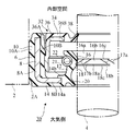
図1に示すように、第1実施形態に係る密封装置1は、歯車減速機のハウジング2と、ハウジング2に設けられた孔2A内に配置された回転シャフト(回転体)4との間の隙間を封止し、ハウジング2の内部空間と大気側とを隔てる。回転シャフト4は、ロボットのリンク(例えばアーム)を駆動するためのシャフトである。回転シャフト4は、図示しない軸受により回転可能に支持され、孔2Aに同軸に配置されている。回転シャフト4は、歯車減速機の最終最終出力軸であってよいが、他の回転体であってもよい。
First Embodiment As shown in FIG. 1, the
回転シャフト4は円柱状であり、孔2Aは断面円形であり、密封装置1は環状であるが、図1においては、それらの左半分のみが示されている。
The
ハウジング2と回転シャフト4は仮想線で示されている。密封装置1がハウジング2と回転シャフト4との間の隙間に配備された使用状態では、密封装置1は径方向において圧縮されて変形する。
The
密封装置1は、弾性環6と剛性環8を有する複合構造を有する。弾性環6は、弾性材料、例えばエラストマーから形成されている。剛性環8は、剛性材料、例えば金属から形成されており、弾性環6を補強する。剛性環8は、L字形の断面を有しており、スリーブ8Aと、スリーブ8Aの大気側の端部から径方向内側に延びる円環部8Bを有する。
The
密封装置1は、取付け円筒部10、シール円筒部12、連結円環部14、主シールリップ16、副シールリップ18およびダストリップ20を有する。
The
取付け円筒部10は、ハウジング2に取り付けられる。取付け方式は限定されないが、例えば、取付け円筒部10は孔2Aに締まり嵌めされてもよい。取付け円筒部10は、弾性環6と剛性環8から構成されている。より具体的には、取付け円筒部10において、弾性環6は、剛性環8のスリーブ8Aの外周面全体に固着され、剛性環8のスリーブ8Aの内周面全体にも固着されている。したがって、取付け円筒部10は、スリーブ8Aの外周面全体を覆う弾性部10aと、スリーブ8Aの内周面全体を覆う弾性部10bを有する。但し、スリーブ8Aの内周面を弾性材料で覆うことは不可欠ではない。
The mounting
シール円筒部12は、弾性環6のみから構成されており、取付け円筒部10より径方向内側に配置されている。シール円筒部12は、径方向において取付け円筒部10に重なっている。
The seal
連結円環部14は、取付け円筒部10の大気側の端部とシール円筒部12の大気側の端部を径方向において連結する。連結円環部14は、弾性環6と剛性環8から構成されている。より具体的には、連結円環部14において、弾性環6は、剛性環8の円環部8Bの大気側の面全体に固着され、剛性環8の円環部8Bの内部空間側の面の一部にも固着されている。したがって、連結円環部14は、円環部8Bの大気側の面全体を覆う弾性部14aと、円環部8Bの内部空間側の面の一部を覆う弾性部14bを有する。
The connecting
主シールリップ16は、シール円筒部12の内周面から突出する突起であり、内部空間側に配置されたグリース側傾斜面16aと、大気側に配置された大気側傾斜面16bと、グリース側傾斜面16aと大気側傾斜面16bの間の境界にあって周方向に延びるリップエッジ16cを有する。グリース側傾斜面16aは、円錐台の側面の形状を有し、リップエッジ16cから離れるほど回転軸4から離れるよう傾斜する。大気側傾斜面16bも、円錐台の側面の形状を有し、リップエッジ16cから離れるほど回転軸4から離れるよう傾斜する。密封装置1がハウジング2と回転シャフト4との間の隙間に配備された使用状態では、主シールリップ16のリップエッジ16cおよびその付近は、常に回転シャフト4の外周面に摺動可能に接触させられる。
The
主シールリップ16の大気側傾斜面16bには、螺旋リブ17a,17bが形成されている。螺旋リブ17a,17bは、特許第4702517号明細書に記載されているように、リップエッジ16cから大気側に漏れたグリースを回転軸4の回転に伴って、内部空間に戻すポンピング作用をもたらす。但し、螺旋リブ17a,17bは不可欠ではない。
副シールリップ18も、シール円筒部12の内周面から突出する突起である。副シールリップ18は、主シールリップ16よりも大気側に配置されており、主シールリップ16の内径よりも大きい内径を有する。副シールリップ18は、内部空間側に配置されたグリース側傾斜面18aと、大気側に配置された大気側傾斜面18bと、グリース側傾斜面18aと大気側傾斜面18bの間の境界にあって周方向に延びるリップエッジ18cを有する。グリース側傾斜面18aは、円錐台の側面の形状を有し、リップエッジ18cから離れるほど回転軸4から離れるよう傾斜する。大気側傾斜面18bも、円錐台の側面の形状を有し、リップエッジ18cから離れるほど回転軸4から離れるよう傾斜する。密封装置1がハウジング2と回転シャフト4との間の隙間に配備された使用状態で、圧力が与えられないときには、副シールリップ18は、回転シャフト4の外周面に接触しない。すなわち、副シールリップ18と回転シャフト4の外周面の間には隙間がある。但し、シール円筒部12に外側から圧力が与えられるときに、副シールリップ18のリップエッジ18cおよびその付近は、回転シャフト4の外周面に摺動可能に接触させられる。
The
ダストリップ20は、連結円環部14の内周面から径方向内側かつ大気側に向けて斜めに延びる円錐台状の板である。ダストリップ20は、大気側から内部空間側への異物(水または塵埃を含む)の侵入を抑制する役割を有する。この実施形態では、密封装置1が回転シャフト4に与えるトルクを低減するため、ダストリップ20は回転シャフト4に接触させられない。しかし、異物の侵入をさらに低減するため、ダストリップ20の先端が回転シャフト4の外周面に摺動可能に接触させられてもよい。
The
主シールリップ16、副シールリップ18およびダストリップ20は、弾性環6のみから構成されている。
The
シール円筒部12の外周面には周溝21が形成され、周溝21にはガータースプリング22が配置されている。ガータースプリング22は、主シールリップ16およびダストリップ20を径方向内側に向けて押圧する。
A
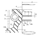
図2および図3の各々は、シール円筒部12、主シールリップ16および副シールリップ18を拡大した断面図である。図2は、密封装置1がハウジング2と回転シャフト4との間の隙間に配備されておらず、シール円筒部12に外側から圧力が与えられない初期状態を示す。
Each of FIGS. 2 and 3 is an enlarged cross-sectional view of the seal
他方、図3は、密封装置1がハウジング2と回転シャフト4との間の隙間に配備された使用状態であって、かつ、シール円筒部12に外側から圧力が与えられた状態(以下、この状態を「圧力付与状態」と呼ぶ)を示す。具体的には、図3において、初期状態(図2の状態)のシール円筒部12、主シールリップ16および副シールリップ18が仮想線で示され、圧力Pによって径方向内側に変位させられた状態のシール円筒部12、主シールリップ16および副シールリップ18が実線で示されている。内部空間のグリースの圧力が高まると、シール円筒部12に外側から圧力Pが加わる。具体的には、シール円筒部12の周囲にグリースが存在する場合には、グリースからシール円筒部12に圧力Pが加わる。シール円筒部12の周囲にグリースが存在しない場合でも、グリースに押圧されたシール円筒部12の周囲の空気からシール円筒部12に圧力Pが加わる。
On the other hand, FIG. 3 shows a state in which the
密封装置1がハウジング2と回転シャフト4との間の隙間に配備されると、主シールリップ16は、常に回転シャフト4の外周面に接触させられるので、圧力Pがなくても初期状態に比べて変形する。さらに、主シールリップ16は、圧力Pによって回転シャフト4の外周面に押し付けられて大きく変形する。したがって、主シールリップ16が回転シャフト4に与える緊縛力が増加する。副シールリップ18は、使用状態であっても圧力Pが与えられないときに、回転シャフト4の外周面に接触しないが、シール円筒部12に外側から圧力Pが与えられるときに、回転シャフト4の外周面に摺動可能に接触させられ、主シールリップ16が回転シャフト4に与える緊縛力の増加を抑制する。したがって、主シールリップ16の摩耗が低減されるとともに、回転シャフト4に与えられるトルクの増加が抑制される。
When the
図2に示すように、シール円筒部12の大気側の端部の最小厚さAは、密封装置1の軸線方向における連結円環部14(具体的には弾性部14b)から主シールリップ16のリップエッジ16cまでの長さBの1/2以下である。連結円環部14は弾性材料と剛性材料から形成されており、高い剛性を有するが、連結円環部14に支持されたシール円筒部12は弾性材料のみから形成され、低い剛性を有しており、シール円筒部12の大気側の端部の最小厚さAは小さい。したがって、シール円筒部12に外側から圧力Pが与えられるときに、シール円筒部12は、副シールリップ18とともに径方向内側に変形しやすく、回転シャフト4の外周面に摺動可能に接触させられやすい。このため、主シールリップ16が回転シャフト4に与える緊縛力の増加を効果的に抑制することができる。
As shown in FIG. 2, the minimum thickness A of the end portion of the seal
また、図2および図3に示すように、副シールリップ18は、ガータースプリング22と径方向において重なる領域に配置されている。図2において、領域Cは、ガータースプリング22と径方向において重なり、この領域Cに副シールリップ18のリップエッジ18cが配置されている。副シールリップ18がガータースプリング22と径方向において重なる領域に配置されていない場合に比べて、ガータースプリング22の圧縮力によって、副シールリップ18は回転シャフト4の外周面に摺動可能に接触させられやすい。このため、主シールリップ16が回転シャフト4に与える緊縛力の増加を効果的に抑制することができる。
Further, as shown in FIGS. 2 and 3, the
発明者は、主シールリップ16に対する副シールリップ18の好適な位置関係を調べるために、有限要素法(FEM)を用いた解析シミュレーションによって、初期状態(図2の状態)での主シールリップ16に対する副シールリップ18の位置と、圧力付与状態(図3の状態)での主シールリップ16の回転シャフト4への接触幅Wの関係を計算した。密封装置1が回転シャフト4に与えるトルクおよび主シールリップ16の摩耗を考慮すると、接触幅Wが小さいことが好ましい。
In order to investigate the suitable positional relationship of the
解析シミュレーションにおいては、圧力付与状態での圧力Pは、0.04MPaに設定した。回転シャフト4の外径Dは49.8mmに設定した。初期状態での主シールリップ16のリップエッジ16cの内径d1は、回転シャフト4の外径Dより小さい49.4mmに設定した。
In the analysis simulation, the pressure P in the pressure-applied state was set to 0.04 MPa. The outer diameter D of the
そして、初期状態での密封装置1の軸線方向における主シールリップ16のリップエッジ16cと副シールリップ18のリップエッジ18cの間の距離(リップ間距離)L、および初期状態での副シールリップ18のリップエッジ18cの内径d2を変更した。初期状態での主シールリップ16の大気側傾斜面16bと副シールリップ18のグリース側傾斜面18aの境界、すなわち谷部24の内径d3は、リップエッジ18cの内径d2より大きくなるよう変更した。
Then, the distance (inter-lip distance) L between the
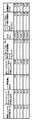
図4は、解析シミュレーションで使用されたパラメータとシミュレーションの結果を示す。初期状態でのリップエッジ18cの内径d2の変更に伴って、初期状態でのリップエッジ16cとリップエッジ18cの間の径方向距離gは変化し、初期状態でのリップエッジ18cと回転シャフト4の間の隙間Gも変化する。初期状態での軸線方向のリップ間距離Lに対するリップエッジ16cとリップエッジ18cの間の径方向距離gの比であるtanθも変化する。θは、密封装置1の軸線に対する初期状態でのリップエッジ16cとリップエッジ18cを結ぶ仮想的な円錐の母線の傾斜角である。
FIG. 4 shows the parameters used in the analysis simulation and the simulation results. With the change of the inner diameter d 2 of the
図4から明らかなように、初期状態での軸線方向のリップ間距離Lが大きいほど、圧力付与状態での主シールリップ16の回転シャフト4への接触幅Wは大きかった。tanθの変化と接触幅Wの関係は判然としなかった。
As is clear from FIG. 4, the larger the distance L between the lips in the axial direction in the initial state, the larger the contact width W of the
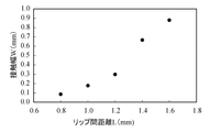
図5は、初期状態での軸線方向のリップ間距離Lと圧力付与状態での接触幅Wの関係を示す。図5から明らかなように、リップ間距離Lが0.8mm〜1.2mmまでは接触幅Wの上昇率は小さいが、リップ間距離Lが1.2mmを超えると接触幅Wの上昇率が大きい。つまり、リップ間距離Lが1.2mmを超えると、使用状態での主シールリップ16の回転シャフト4への接触幅Wが顕著に大きくなり、回転シャフト4に与えられるトルクおよび主シールリップ16の摩耗が顕著に増加する。リップ間距離Lが1.2mm以下であれば、回転シャフト4に与えられるトルクの増加および主シールリップ16の摩耗を抑制することができる。したがって、初期状態での密封装置1の軸線方向における主シールリップ16のリップエッジ16cから副シールリップ18のリップエッジ18cまでの距離が1.2mm以下であることが好ましい。
FIG. 5 shows the relationship between the distance between lips in the axial direction in the initial state and the contact width W in the pressure-applied state. As is clear from FIG. 5, the rate of increase of the contact width W is small when the distance L between lips is 0.8 mm to 1.2 mm, but the rate of increase of the contact width W increases when the distance L between lips exceeds 1.2 mm. large. That is, when the distance L between lips exceeds 1.2 mm, the contact width W of the
第2実施形態
図6は、本発明の第2実施形態に係る密封装置30の部分断面図である。図6において、すでに説明した構成要素を示すため、同一の符号が使用され、それらの構成要素については詳細には説明しない。
Second Embodiment FIG. 6 is a partial cross-sectional view of the sealing
密封装置30は、第1実施形態に係る密封装置1と類似の基本構成に加え、さらに補助シール32を有する。補助シール32は、基本構成に対して着脱自在であり、基本構成の取付け円筒部10の内側に配置されている。
The sealing
補助シール32は、弾性環34と剛性環36を有する複合構造を有する。弾性環34は、弾性材料、例えばエラストマーから形成されている。剛性環36は、剛性材料、例えば金属から形成されており、弾性環34を補強する。剛性環36は、ほぼL字形の断面を有しており、スリーブ36Aと、スリーブ36Aの内部空間側の端部から径方向内側に延びる円環部36Bを有する。剛性環36のスリーブ36Aは、取付け円筒部10の弾性部10bに締まり嵌め方式で嵌め込まれている。
The auxiliary seal 32 has a composite structure having an
弾性環34は、剛性環36の円環部36Bより径方向内側に配置された補助リップ38を有する。補助リップ38は、基本構成の主シールリップ16より内部空間側に配置されている。補助リップ38の先端は、回転シャフト4の外周面に摺動可能に接触させられる。
The
この実施形態によれば、補助シール32によって、内部空間に配置されたグリースが大気側に漏出することが抑制される。但し、補助リップ38と回転シャフト4の外周面の間の微小隙間がありうるので、内部空間内のグリースの圧力が高まると、シール円筒部12に外側から圧力Pが加わりうる。また、補助リップ38の摩耗に伴って、内部空間内のグリースが補助リップ38を乗り越えて大気側に侵入しうるので、この場合もシール円筒部12に外側から圧力Pが加わりうる。第1実施形態と同様に、シール円筒部12、主シールリップ16および副シールリップ18を形成することにより、主シールリップ16が回転シャフト4に与える緊縛力の増加を抑制し、主シールリップ16の摩耗を低減し、回転シャフト4に与えられるトルクの増加を抑制することができる。
According to this embodiment, the auxiliary seal 32 prevents the grease arranged in the internal space from leaking to the atmosphere side. However, since there may be a minute gap between the
変形例
以上、本発明の好ましい実施形態を参照しながら本発明を図示して説明したが、当業者にとって特許請求の範囲に記載された発明の範囲から逸脱することなく、形式および詳細の変更が可能であることが理解されるであろう。このような変更、改変および修正は本発明の範囲に包含されるはずである。
Modified Examples Although the present invention has been illustrated and described with reference to preferred embodiments of the present invention, those skilled in the art can change the form and details without departing from the scope of the invention described in the claims. It will be understood that it is possible. Such changes, modifications and modifications should be within the scope of the present invention.
例えば、上記の実施形態において、密封装置は、関節型ロボットのリンクを駆動するための歯車減速機のハウジングの内部空間内にグリースを密封するために、歯車減速機のハウジング2と、ハウジング2に設けられた孔2A内に配置された回転シャフト4との間の隙間を封止する。しかし、密封装置は、他の歯車減速機のハウジングの内部空間内にグリースを密封するために使用されてもよい。
For example, in the above embodiment, the sealing device is applied to the
また、密封装置は、歯車減速機以外の装置のハウジングの内部空間内にグリースを密封するために、ハウジングと、ハウジングに設けられた孔内で低速回転する回転体との間の隙間を封止する使用されてもよい。例えば、精密機械のターンテーブルの回転軸と、回転軸のハウジングとの間の隙間を封止するために、密封装置が使用されてもよい。あるいは、旋回型カメラまたは旋回型送風機の回転軸と、回転軸のハウジングとの間の隙間を封止するために、密封装置が使用されてもよい。 Further, the sealing device seals a gap between the housing and a rotating body that rotates at a low speed in a hole provided in the housing in order to seal the grease in the internal space of the housing of the device other than the gear reducer. May be used. For example, a sealing device may be used to seal the gap between the rotating shaft of the turntable of a precision machine and the housing of the rotating shaft. Alternatively, a sealing device may be used to seal the gap between the rotating shaft of the swivel camera or swivel blower and the housing of the swivel shaft.
回転シャフト4の周囲に他の部品(例えば、スリーブ)を配置し、主シールリップ16がこの部品の外周面に摺動可能に接触させられてもよく、副シールリップ18は、圧力が与えられないときに、この部品の外周面に接触せず、シール円筒部12に外側から圧力が与えられるときに、この部品の外周面に摺動可能に接触させられるようにしてもよい。この場合、回転シャフト4とこの部品の組み合わせを回転体とみなすことができる。
Another component (eg, a sleeve) may be placed around the
本発明の態様は、下記の番号付けされた条項にも記載される。 Aspects of the invention are also described in the numbered clauses below.
条項1. ハウジングと、前記ハウジングに設けられた孔内に配置された回転体との間の隙間を封止し、前記ハウジングの内部空間と大気側とを隔てる密封装置であって、
前記ハウジングに取り付けられる取付け円筒部と、
前記取付け円筒部より径方向内側に配置されたシール円筒部と、
前記取付け円筒部の大気側の端部と前記シール円筒部の大気側の端部を径方向において連結する連結円環部と、
前記シール円筒部の内周面から突出し、前記回転体の外周面に摺動可能に接触させられる主シールリップと、
前記シール円筒部の内周面から突出し、前記主シールリップよりも大気側に配置されており、前記主シールリップよりも内径が大きい副シールリップとを有しており、
前記副シールリップは、圧力が与えられないときに、前記回転体の外周面に接触せず、前記シール円筒部に外側から圧力が与えられるときに、前記回転体の外周面に摺動可能に接触させられ、
前記シール円筒部、前記主シールリップおよび前記副シールリップは、弾性材料のみから形成され、
前記取付け円筒部および前記連結円環部は、前記弾性材料と剛性材料から形成されており、
前記シール円筒部の大気側の端部の最小厚さは、密封装置の軸線方向における前記連結円環部から前記主シールリップのリップエッジまでの長さの1/2以下である
ことを特徴とする密封装置。
The mounting cylinder to be mounted on the housing and
A seal cylindrical portion arranged radially inside the mounting cylindrical portion,
A connecting ring portion that connects the end portion of the mounting cylinder portion on the atmosphere side and the end portion of the seal cylinder portion on the atmosphere side in the radial direction,
A main seal lip that protrudes from the inner peripheral surface of the seal cylindrical portion and is slidably contacted with the outer peripheral surface of the rotating body.
It has a secondary seal lip that protrudes from the inner peripheral surface of the seal cylindrical portion, is arranged on the atmosphere side of the main seal lip, and has an inner diameter larger than that of the main seal lip.
The sub-seal lip does not come into contact with the outer peripheral surface of the rotating body when no pressure is applied, and is slidable on the outer peripheral surface of the rotating body when pressure is applied to the seal cylindrical portion from the outside. Be contacted,
The seal cylinder, the main seal lip and the sub seal lip are made of elastic material only.
The mounting cylindrical portion and the connecting annular portion are formed of the elastic material and the rigid material.
The minimum thickness of the end portion of the seal cylinder portion on the atmosphere side is ½ or less of the length from the connecting ring portion to the lip edge of the main seal lip in the axial direction of the sealing device. Sealing device.
条項2. 前記シール円筒部の周囲に配置されたガータースプリングをさらに有しており、
前記副シールリップは、前記ガータースプリングと径方向において重なる領域に配置されている
ことを特徴とする条項1に記載の密封装置。
The sealing device according to
この条項によれば、副シールリップがガータースプリングと径方向において重なる領域に配置されていない場合に比べて、ガータースプリングの圧縮力によって、副シールリップは回転体の外周面に摺動可能に接触させられやすい。このため、主シールリップが回転体に与える緊縛力の増加を効果的に抑制することができる。 According to this clause, the compressive force of the garter spring causes the secondary seal lip to slidably contact the outer peripheral surface of the rotating body, as compared to the case where the secondary seal lip is not located in the area where it radially overlaps the garter spring. Easy to be forced. Therefore, it is possible to effectively suppress an increase in the binding force exerted by the main seal lip on the rotating body.
条項3. 密封装置の軸線方向における前記主シールリップの前記リップエッジから前記副シールリップのリップエッジまでの距離が1.2mm以下である
ことを特徴とする条項1または2に記載の密封装置。
Clause 3. The sealing device according to
この距離が1.2mmを超えると、使用状態での主シールリップの回転体への接触幅が顕著に大きくなり、回転体に与えられるトルクおよび主シールリップの摩耗が顕著に増加する。この距離が1.2mm以下であれば、回転体に与えられるトルクの増加および主シールリップの摩耗を抑制することができる。 When this distance exceeds 1.2 mm, the contact width of the main seal lip with the rotating body in the used state becomes remarkably large, and the torque applied to the rotating body and the wear of the main seal lip increase remarkably. When this distance is 1.2 mm or less, an increase in torque applied to the rotating body and wear of the main seal lip can be suppressed.
条項4. 前記取付け円筒部の内側に配置された補助シールをさらに有しており、
前記補助シールは、前記取付け円筒部に嵌め込まれるスリーブと、前記スリーブより径方向内側かつ前記主シールリップより内部空間側に配置されて、前記回転体の外周面に摺動可能に接触させられる補助リップとを有する
ことを特徴とする条項1から3のいずれか1項に記載の密封装置。
The auxiliary seal is arranged on the sleeve fitted in the mounting cylinder portion in the radial direction from the sleeve and on the internal space side from the main seal lip, and is slidably brought into contact with the outer peripheral surface of the rotating body. The sealing device according to any one of
この条項によれば、補助シールによって、内部空間に配置されたグリースが大気側に漏出することが抑制される。 According to this clause, the auxiliary seal prevents the grease placed in the internal space from leaking to the atmosphere.
1 密封装置
2 ハウジング
2A 孔
4 回転シャフト(回転体)
10 取付け円筒部
12 シール円筒部
14 連結円環部
16 主シールリップ
16c リップエッジ
18 副シールリップ
18c リップエッジ
22 ガータースプリング
30 密封装置
32 補助シール
38 補助リップ
1
10
Claims (4)
前記ハウジングに取り付けられる取付け円筒部と、
前記取付け円筒部より径方向内側に配置されたシール円筒部と、
前記取付け円筒部の大気側の端部と前記シール円筒部の大気側の端部を径方向において連結する連結円環部と、
前記シール円筒部の内周面から突出し、前記回転体の外周面に摺動可能に接触させられる主シールリップと、
前記シール円筒部の内周面から突出し、前記主シールリップよりも大気側に配置されており、前記主シールリップよりも内径が大きい副シールリップとを有しており、
前記副シールリップは、圧力が与えられないときに、前記回転体の外周面に接触せず、前記シール円筒部に外側から圧力が与えられるときに、前記回転体の外周面に摺動可能に接触させられ、
前記シール円筒部、前記主シールリップおよび前記副シールリップは、弾性材料のみから形成され、
前記取付け円筒部および前記連結円環部は、前記弾性材料と剛性材料から形成されており、
前記シール円筒部の大気側の端部の最小厚さは、密封装置の軸線方向における前記連結円環部から前記主シールリップのリップエッジまでの長さの1/2以下である
ことを特徴とする密封装置。 A sealing device that seals a gap between a housing and a rotating body arranged in a hole provided in the housing and separates the internal space of the housing from the atmosphere side.
The mounting cylinder to be mounted on the housing and
A seal cylindrical portion arranged radially inside the mounting cylindrical portion,
A connecting ring portion that connects the end portion of the mounting cylinder portion on the atmosphere side and the end portion of the seal cylinder portion on the atmosphere side in the radial direction,
A main seal lip that protrudes from the inner peripheral surface of the seal cylindrical portion and is slidably contacted with the outer peripheral surface of the rotating body.
It has a secondary seal lip that protrudes from the inner peripheral surface of the seal cylindrical portion, is arranged on the atmosphere side of the main seal lip, and has an inner diameter larger than that of the main seal lip.
The sub-seal lip does not come into contact with the outer peripheral surface of the rotating body when no pressure is applied, and can slide on the outer peripheral surface of the rotating body when pressure is applied to the seal cylindrical portion from the outside. Be contacted,
The seal cylinder, the main seal lip and the sub seal lip are made of elastic material only.
The mounting cylindrical portion and the connecting annular portion are formed of the elastic material and the rigid material.
The minimum thickness of the end portion of the seal cylinder portion on the atmosphere side is ½ or less of the length from the connecting ring portion to the lip edge of the main seal lip in the axial direction of the sealing device. Sealing device.
前記副シールリップは、前記ガータースプリングと径方向において重なる領域に配置されている
ことを特徴とする請求項1に記載の密封装置。 It further has a garter spring arranged around the seal cylinder.
The sealing device according to claim 1, wherein the sub-seal lip is arranged in a region overlapping the garter spring in the radial direction.
ことを特徴とする請求項1または2に記載の密封装置。 The sealing device according to claim 1 or 2, wherein the distance from the lip edge of the main sealing lip to the lip edge of the secondary sealing lip in the axial direction of the sealing device is 1.2 mm or less.
前記補助シールは、前記取付け円筒部に嵌め込まれるスリーブと、前記スリーブより径方向内側かつ前記主シールリップより内部空間側に配置されて、前記回転体の外周面に摺動可能に接触させられる補助リップとを有する
ことを特徴とする請求項1から3のいずれか1項に記載の密封装置。 It also has an auxiliary seal located inside the mounting cylinder.
The auxiliary seal is arranged on the sleeve fitted in the mounting cylinder portion in the radial direction from the sleeve and on the internal space side from the main seal lip, and is slidably brought into contact with the outer peripheral surface of the rotating body. The sealing device according to any one of claims 1 to 3, further comprising a lip.
Priority Applications (2)
| Application Number | Priority Date | Filing Date | Title |
|---|---|---|---|
| JP2019087419A JP7378958B2 (en) | 2019-05-07 | 2019-05-07 | sealing device |
| CN202020470609.6U CN212251132U (en) | 2019-05-07 | 2020-04-02 | Sealing device |
Applications Claiming Priority (1)
| Application Number | Priority Date | Filing Date | Title |
|---|---|---|---|
| JP2019087419A JP7378958B2 (en) | 2019-05-07 | 2019-05-07 | sealing device |
Publications (2)
| Publication Number | Publication Date |
|---|---|
| JP2020183776A true JP2020183776A (en) | 2020-11-12 |
| JP7378958B2 JP7378958B2 (en) | 2023-11-14 |
Family
ID=73044927
Family Applications (1)
| Application Number | Title | Priority Date | Filing Date |
|---|---|---|---|
| JP2019087419A Active JP7378958B2 (en) | 2019-05-07 | 2019-05-07 | sealing device |
Country Status (2)
| Country | Link |
|---|---|
| JP (1) | JP7378958B2 (en) |
| CN (1) | CN212251132U (en) |
Families Citing this family (2)
| Publication number | Priority date | Publication date | Assignee | Title |
|---|---|---|---|---|
| CN117052905B (en) * | 2023-10-11 | 2023-12-29 | 万向钱潮股份公司 | Sealing device for universal joint |
| IT202300022824A1 (en) * | 2023-10-30 | 2025-04-30 | Skf Ab | SEALING ASSEMBLY FOR INTERPOSITION BETWEEN A STATIONARY ANNUAL ELEMENT AND A SLIDING ANNUAL ELEMENT, IN PARTICULAR A SHEATH AND A VEHICLE SHOCK ABSORBER STEM |
Citations (7)
| Publication number | Priority date | Publication date | Assignee | Title |
|---|---|---|---|---|
| JPH0673547U (en) * | 1993-03-31 | 1994-10-18 | 株式会社荒井製作所 | Oil seal with auxiliary lip |
| JPH1194093A (en) * | 1997-09-19 | 1999-04-09 | Nok Corp | Sealing device |
| JP2003240126A (en) * | 2002-02-15 | 2003-08-27 | Koyo Sealing Techno Co Ltd | Seal ring |
| JP2006083955A (en) * | 2004-09-16 | 2006-03-30 | Arai Pump Mfg Co Ltd | Sealing device |
| CN202612644U (en) * | 2012-05-07 | 2012-12-19 | 李加宝 | Oil seal ring of high-pressure plunger pump |
| JP2015048855A (en) * | 2013-08-29 | 2015-03-16 | 光洋シーリングテクノ株式会社 | Seal member |
| JP2015169279A (en) * | 2014-03-07 | 2015-09-28 | 光洋シーリングテクノ株式会社 | sealing device |
-
2019
- 2019-05-07 JP JP2019087419A patent/JP7378958B2/en active Active
-
2020
- 2020-04-02 CN CN202020470609.6U patent/CN212251132U/en active Active
Patent Citations (7)
| Publication number | Priority date | Publication date | Assignee | Title |
|---|---|---|---|---|
| JPH0673547U (en) * | 1993-03-31 | 1994-10-18 | 株式会社荒井製作所 | Oil seal with auxiliary lip |
| JPH1194093A (en) * | 1997-09-19 | 1999-04-09 | Nok Corp | Sealing device |
| JP2003240126A (en) * | 2002-02-15 | 2003-08-27 | Koyo Sealing Techno Co Ltd | Seal ring |
| JP2006083955A (en) * | 2004-09-16 | 2006-03-30 | Arai Pump Mfg Co Ltd | Sealing device |
| CN202612644U (en) * | 2012-05-07 | 2012-12-19 | 李加宝 | Oil seal ring of high-pressure plunger pump |
| JP2015048855A (en) * | 2013-08-29 | 2015-03-16 | 光洋シーリングテクノ株式会社 | Seal member |
| JP2015169279A (en) * | 2014-03-07 | 2015-09-28 | 光洋シーリングテクノ株式会社 | sealing device |
Also Published As
| Publication number | Publication date |
|---|---|
| JP7378958B2 (en) | 2023-11-14 |
| CN212251132U (en) | 2020-12-29 |
Similar Documents
| Publication | Publication Date | Title |
|---|---|---|
| WO2021182057A1 (en) | Sealing device and reduction gear | |
| WO2020045070A1 (en) | Sealing device | |
| JP4471079B2 (en) | Sealing device | |
| JP7378958B2 (en) | sealing device | |
| JP7042909B2 (en) | Sealing device and sealing method using a sealing device | |
| JP2018119681A (en) | Rotary machine seal structure, rotary machine and seal member | |
| JP6378548B2 (en) | Sealing device | |
| JP4448105B2 (en) | Compressor seal structure | |
| EP1553336A1 (en) | Multistage oil seal for machine tool motor | |
| JP2009097607A (en) | Oil seal | |
| WO2017094599A1 (en) | Seal device | |
| JP2020186768A (en) | Seal device | |
| JP6868386B2 (en) | Sealing device | |
| JP4415600B2 (en) | Sealing structure with oil seal | |
| JP7011716B2 (en) | Sealing device | |
| JP2017067268A (en) | Sealing device | |
| JP7133640B2 (en) | Sealing device and sealing structure | |
| CN111902662B (en) | Sealing means | |
| JP2020067106A (en) | Sealing device | |
| JP2008169933A (en) | Sealing device | |
| JP3186473U (en) | Sealing device | |
| JP2006083955A (en) | Sealing device | |
| JP6368152B2 (en) | Sealing device | |
| JP6116877B2 (en) | Sealing device | |
| JP2011106494A (en) | Sealing device |
Legal Events
| Date | Code | Title | Description |
|---|---|---|---|
| A621 | Written request for application examination |
Free format text: JAPANESE INTERMEDIATE CODE: A621 Effective date: 20220406 |
|
| A977 | Report on retrieval |
Free format text: JAPANESE INTERMEDIATE CODE: A971007 Effective date: 20221215 |
|
| A131 | Notification of reasons for refusal |
Free format text: JAPANESE INTERMEDIATE CODE: A131 Effective date: 20230110 |
|
| A521 | Request for written amendment filed |
Free format text: JAPANESE INTERMEDIATE CODE: A523 Effective date: 20230307 |
|
| A02 | Decision of refusal |
Free format text: JAPANESE INTERMEDIATE CODE: A02 Effective date: 20230620 |
|
| A521 | Request for written amendment filed |
Free format text: JAPANESE INTERMEDIATE CODE: A523 Effective date: 20230914 |
|
| A911 | Transfer to examiner for re-examination before appeal (zenchi) |
Free format text: JAPANESE INTERMEDIATE CODE: A911 Effective date: 20230922 |
|
| TRDD | Decision of grant or rejection written | ||
| A01 | Written decision to grant a patent or to grant a registration (utility model) |
Free format text: JAPANESE INTERMEDIATE CODE: A01 Effective date: 20231017 |
|
| A61 | First payment of annual fees (during grant procedure) |
Free format text: JAPANESE INTERMEDIATE CODE: A61 Effective date: 20231101 |
|
| R150 | Certificate of patent or registration of utility model |
Ref document number: 7378958 Country of ref document: JP Free format text: JAPANESE INTERMEDIATE CODE: R150 |