EP3781237B1 - Syringe adapter with aspiration assembly - Google Patents
Syringe adapter with aspiration assembly Download PDFInfo
- Publication number
- EP3781237B1 EP3781237B1 EP19719145.5A EP19719145A EP3781237B1 EP 3781237 B1 EP3781237 B1 EP 3781237B1 EP 19719145 A EP19719145 A EP 19719145A EP 3781237 B1 EP3781237 B1 EP 3781237B1
- Authority
- EP
- European Patent Office
- Prior art keywords
- aspiration
- housing
- opening
- cannula
- way valve
- Prior art date
- Legal status (The legal status is an assumption and is not a legal conclusion. Google has not performed a legal analysis and makes no representation as to the accuracy of the status listed.)
- Active
Links
Images


Classifications
-
- A—HUMAN NECESSITIES
- A61—MEDICAL OR VETERINARY SCIENCE; HYGIENE
- A61M—DEVICES FOR INTRODUCING MEDIA INTO, OR ONTO, THE BODY; DEVICES FOR TRANSDUCING BODY MEDIA OR FOR TAKING MEDIA FROM THE BODY; DEVICES FOR PRODUCING OR ENDING SLEEP OR STUPOR
- A61M5/00—Devices for bringing media into the body in a subcutaneous, intra-vascular or intramuscular way; Accessories therefor, e.g. filling or cleaning devices, arm-rests
- A61M5/178—Syringes
- A61M5/31—Details
- A61M5/3148—Means for causing or aiding aspiration or plunger retraction
-
- A—HUMAN NECESSITIES
- A61—MEDICAL OR VETERINARY SCIENCE; HYGIENE
- A61J—CONTAINERS SPECIALLY ADAPTED FOR MEDICAL OR PHARMACEUTICAL PURPOSES; DEVICES OR METHODS SPECIALLY ADAPTED FOR BRINGING PHARMACEUTICAL PRODUCTS INTO PARTICULAR PHYSICAL OR ADMINISTERING FORMS; DEVICES FOR ADMINISTERING FOOD OR MEDICINES ORALLY; BABY COMFORTERS; DEVICES FOR RECEIVING SPITTLE
- A61J1/00—Containers specially adapted for medical or pharmaceutical purposes
- A61J1/14—Details; Accessories therefor
- A61J1/20—Arrangements for transferring or mixing fluids, e.g. from vial to syringe
- A61J1/2096—Combination of a vial and a syringe for transferring or mixing their contents
-
- A—HUMAN NECESSITIES
- A61—MEDICAL OR VETERINARY SCIENCE; HYGIENE
- A61J—CONTAINERS SPECIALLY ADAPTED FOR MEDICAL OR PHARMACEUTICAL PURPOSES; DEVICES OR METHODS SPECIALLY ADAPTED FOR BRINGING PHARMACEUTICAL PRODUCTS INTO PARTICULAR PHYSICAL OR ADMINISTERING FORMS; DEVICES FOR ADMINISTERING FOOD OR MEDICINES ORALLY; BABY COMFORTERS; DEVICES FOR RECEIVING SPITTLE
- A61J1/00—Containers specially adapted for medical or pharmaceutical purposes
- A61J1/14—Details; Accessories therefor
- A61J1/20—Arrangements for transferring or mixing fluids, e.g. from vial to syringe
- A61J1/2003—Accessories used in combination with means for transfer or mixing of fluids, e.g. for activating fluid flow, separating fluids, filtering fluid or venting
- A61J1/2006—Piercing means
- A61J1/201—Piercing means having one piercing end
-
- A—HUMAN NECESSITIES
- A61—MEDICAL OR VETERINARY SCIENCE; HYGIENE
- A61J—CONTAINERS SPECIALLY ADAPTED FOR MEDICAL OR PHARMACEUTICAL PURPOSES; DEVICES OR METHODS SPECIALLY ADAPTED FOR BRINGING PHARMACEUTICAL PRODUCTS INTO PARTICULAR PHYSICAL OR ADMINISTERING FORMS; DEVICES FOR ADMINISTERING FOOD OR MEDICINES ORALLY; BABY COMFORTERS; DEVICES FOR RECEIVING SPITTLE
- A61J1/00—Containers specially adapted for medical or pharmaceutical purposes
- A61J1/14—Details; Accessories therefor
- A61J1/20—Arrangements for transferring or mixing fluids, e.g. from vial to syringe
- A61J1/2003—Accessories used in combination with means for transfer or mixing of fluids, e.g. for activating fluid flow, separating fluids, filtering fluid or venting
- A61J1/202—Separating means
- A61J1/2037—Separating means having valve means
-
- A—HUMAN NECESSITIES
- A61—MEDICAL OR VETERINARY SCIENCE; HYGIENE
- A61J—CONTAINERS SPECIALLY ADAPTED FOR MEDICAL OR PHARMACEUTICAL PURPOSES; DEVICES OR METHODS SPECIALLY ADAPTED FOR BRINGING PHARMACEUTICAL PRODUCTS INTO PARTICULAR PHYSICAL OR ADMINISTERING FORMS; DEVICES FOR ADMINISTERING FOOD OR MEDICINES ORALLY; BABY COMFORTERS; DEVICES FOR RECEIVING SPITTLE
- A61J1/00—Containers specially adapted for medical or pharmaceutical purposes
- A61J1/14—Details; Accessories therefor
- A61J1/20—Arrangements for transferring or mixing fluids, e.g. from vial to syringe
- A61J1/2003—Accessories used in combination with means for transfer or mixing of fluids, e.g. for activating fluid flow, separating fluids, filtering fluid or venting
- A61J1/2048—Connecting means
-
- A—HUMAN NECESSITIES
- A61—MEDICAL OR VETERINARY SCIENCE; HYGIENE
- A61J—CONTAINERS SPECIALLY ADAPTED FOR MEDICAL OR PHARMACEUTICAL PURPOSES; DEVICES OR METHODS SPECIALLY ADAPTED FOR BRINGING PHARMACEUTICAL PRODUCTS INTO PARTICULAR PHYSICAL OR ADMINISTERING FORMS; DEVICES FOR ADMINISTERING FOOD OR MEDICINES ORALLY; BABY COMFORTERS; DEVICES FOR RECEIVING SPITTLE
- A61J1/00—Containers specially adapted for medical or pharmaceutical purposes
- A61J1/14—Details; Accessories therefor
- A61J1/20—Arrangements for transferring or mixing fluids, e.g. from vial to syringe
- A61J1/2003—Accessories used in combination with means for transfer or mixing of fluids, e.g. for activating fluid flow, separating fluids, filtering fluid or venting
- A61J1/2079—Filtering means
- A61J1/2082—Filtering means for gas filtration
-
- A—HUMAN NECESSITIES
- A61—MEDICAL OR VETERINARY SCIENCE; HYGIENE
- A61J—CONTAINERS SPECIALLY ADAPTED FOR MEDICAL OR PHARMACEUTICAL PURPOSES; DEVICES OR METHODS SPECIALLY ADAPTED FOR BRINGING PHARMACEUTICAL PRODUCTS INTO PARTICULAR PHYSICAL OR ADMINISTERING FORMS; DEVICES FOR ADMINISTERING FOOD OR MEDICINES ORALLY; BABY COMFORTERS; DEVICES FOR RECEIVING SPITTLE
- A61J1/00—Containers specially adapted for medical or pharmaceutical purposes
- A61J1/14—Details; Accessories therefor
- A61J1/20—Arrangements for transferring or mixing fluids, e.g. from vial to syringe
- A61J1/2003—Accessories used in combination with means for transfer or mixing of fluids, e.g. for activating fluid flow, separating fluids, filtering fluid or venting
- A61J1/2068—Venting means
- A61J1/2075—Venting means for external venting
-
- A—HUMAN NECESSITIES
- A61—MEDICAL OR VETERINARY SCIENCE; HYGIENE
- A61M—DEVICES FOR INTRODUCING MEDIA INTO, OR ONTO, THE BODY; DEVICES FOR TRANSDUCING BODY MEDIA OR FOR TAKING MEDIA FROM THE BODY; DEVICES FOR PRODUCING OR ENDING SLEEP OR STUPOR
- A61M5/00—Devices for bringing media into the body in a subcutaneous, intra-vascular or intramuscular way; Accessories therefor, e.g. filling or cleaning devices, arm-rests
- A61M5/178—Syringes
- A61M5/31—Details
- A61M2005/3123—Details having air entrapping or venting means, e.g. purging channels in pistons
-
- A—HUMAN NECESSITIES
- A61—MEDICAL OR VETERINARY SCIENCE; HYGIENE
- A61M—DEVICES FOR INTRODUCING MEDIA INTO, OR ONTO, THE BODY; DEVICES FOR TRANSDUCING BODY MEDIA OR FOR TAKING MEDIA FROM THE BODY; DEVICES FOR PRODUCING OR ENDING SLEEP OR STUPOR
- A61M39/00—Tubes, tube connectors, tube couplings, valves, access sites or the like, specially adapted for medical use
- A61M39/10—Tube connectors; Tube couplings
- A61M2039/1072—Tube connectors; Tube couplings with a septum present in the connector
-
- A—HUMAN NECESSITIES
- A61—MEDICAL OR VETERINARY SCIENCE; HYGIENE
- A61M—DEVICES FOR INTRODUCING MEDIA INTO, OR ONTO, THE BODY; DEVICES FOR TRANSDUCING BODY MEDIA OR FOR TAKING MEDIA FROM THE BODY; DEVICES FOR PRODUCING OR ENDING SLEEP OR STUPOR
- A61M39/00—Tubes, tube connectors, tube couplings, valves, access sites or the like, specially adapted for medical use
- A61M39/22—Valves or arrangement of valves
- A61M39/24—Check- or non-return valves
- A61M2039/2433—Valve comprising a resilient or deformable element, e.g. flap valve, deformable disc
-
- A—HUMAN NECESSITIES
- A61—MEDICAL OR VETERINARY SCIENCE; HYGIENE
- A61M—DEVICES FOR INTRODUCING MEDIA INTO, OR ONTO, THE BODY; DEVICES FOR TRANSDUCING BODY MEDIA OR FOR TAKING MEDIA FROM THE BODY; DEVICES FOR PRODUCING OR ENDING SLEEP OR STUPOR
- A61M39/00—Tubes, tube connectors, tube couplings, valves, access sites or the like, specially adapted for medical use
- A61M39/22—Valves or arrangement of valves
- A61M39/26—Valves closing automatically on disconnecting the line and opening on reconnection thereof
- A61M2039/261—Valves closing automatically on disconnecting the line and opening on reconnection thereof where the fluid space within the valve is increasing upon disconnection
Definitions
- the clinician or care provider may be exposed to the medical fluid resulting in contamination from, for example, vaporized medical fluids or from contaminants released as an aerosol.
- contamination may occur by breathing the vaporized or aerosol contaminates into the lungs.
- Contamination may also occur when vaporized or aerosol contaminants condense on and then penetrate the clinician's or care provider's skin. In some instances, such condensed contaminates may even penetrate protective gloves.
- a CSTD generally includes a syringe adapter for connection to a syringe and another adapter for connection to a vial, a second syringe, a fluid container, or a conduit providing fluid access to the patient's circulatory system.
- the clinician or care provider may reconstitute a powdered or lyophilized compound with saline or some other reconstitution medium by attaching the syringe to the vial via connection of the respective adapters.
- the drug is then reconstituted by injecting fluid from the syringe, through the respective adapters, and into the vial.
- the reconstituted infusion may then be aspirated into the syringe.
- the adapters can be disconnected from one another.
- the clinician or care provider may then attach the syringe to another adapter to transfer fluid from the syringe to a fluid conduit or patient delivery device, such as an IV line or syringe, for administration to the patient.
- a syringe adapter includes a housing having a first end and a second end positioned opposite the first end, with the housing including a connector body positioned at the first end of the housing and configured to be secured to a syringe barrel, a cannula positioned within the housing, with the cannula having a first end and a second end opposite the first end and defining a transfer opening and a valve opening, a seal arrangement positioned within the housing and movable within the housing, with the seal arrangement including a membrane, and an aspiration assembly positioned within the housing.
- the aspiration housing includes an aspiration housing defining an aspiration opening, a filter received by the aspiration housing, and one-way valve received by the aspiration housing, where the valve opening of the cannula is positioned within the aspiration housing, and where air is configured to flow into the filter via the aspiration opening, into the one-way valve, and into the valve opening of the cannula.
- the aspiration assembly may further include a base secured to the aspiration housing and engaging the filter and the one-way valve.
- the base may be secured to the connector body.
- the first end of the cannula may be secured to the connector body, with the cannula extending through the base, the one-way valve, the filter, and the aspiration housing with the second end of the cannula configured to be received by the seal arrangement.
- the one-way valve may prevent the flow of fluid from the one-way valve to the filter and to the aspiration opening of the aspiration housing.
- the seal arrangement may have a first position with the second end of the cannula received within the membrane of the seal arrangement and a second position with the second end of the cannula positioned outside of the membrane of the seal arrangement, with the membrane of the seal arrangement engaging and sealing the aspiration opening of the aspiration housing when the seal arrangement is in the second position. At least a portion of the aspiration assembly may be received within the connector body.
- the valve opening of the cannula may include a plurality of openings.
- the filter and the one-way valve may be annular, with the one-way valve received within the filter.
- the one-way valve may include a valve body and a valve member moveable radially inward relative to the valve body.
- the valve member of the one-way valve may be elastomeric.
- a syringe adapter in a further aspect, includes a housing having a first end and a second end positioned opposite the first end, with the housing including a connector body positioned at the first end of the housing and configured to be secured to a syringe barrel, a cannula positioned within the housing, with the cannula having a first end and a second end opposite the first end, a seal arrangement positioned within the housing and movable within the housing, with the seal arrangement including a membrane, and an aspiration assembly positioned within the housing.
- the aspiration assembly includes an aspiration housing defining an aspiration opening, a filter received by the aspiration housing, and a one-way valve received by the aspiration housing, where air is configured to flow into the aspiration housing via the aspiration opening, through the one way valve, and through the filter.
- the aspiration assembly may further include a base secured to the aspiration housing and engaging the filter.
- the base may define an opening and the connector body may define an opening in fluid communication with the opening of the base and a central passageway of the connector body.
- the connector body may define an opening in fluid communication with the aspiration housing and a central passageway of the connector body, where air is configured to pass through the filter and enter the opening of the connector body.
- the first end of the cannula may be secured to the connector body, with the cannula extending through the filter, the one-way valve, and the aspiration housing with the second end of the cannula configured to be received by the seal arrangement.
- the one-way valve may prevent the flow of fluid from within the aspiration housing to the aspiration opening.
- the seal arrangement may have a first position with the second end of the cannula received within the membrane of the seal arrangement and a second position with the second end of the cannula positioned outside of the membrane of the seal arrangement, with the seal arrangement engaging and sealing the aspiration opening of the aspiration housing when the seal arrangement is in the second position.
- One of the membrane and a sealing gasket may seal the aspiration opening of the aspiration housing when the seal arrangement is in the second position.
- the one-way valve may be an umbrella valve.
- proximal refers to the direction toward the center or central region of the device.
- distal refers to the outward direction extending away from the central region of the device.
- a syringe adapter 10 for connecting a syringe 12 to another medical device, such as a patient connector 14, or fluid container.
- the medical device can be, for example, a patient line, vial adapter, fluid container, or infusion adapter.
- the container can be a medical vial, syringe barrel, IV bag, or similar container for holding a fluid to be administered to a patient.
- the syringe adapter 10 can be used to facilitate closed transfer of fluids between the syringe 12 and medical device or fluid container.
- the syringe adapter 10 includes a housing 20, a cannula 22 positioned within the housing 20, a seal arrangement 24 positioned within the housing 20 and movable within the housing 20 between first and second positions, and an aspiration assembly 26 positioned within the housing 20.
- the aspiration assembly 26 is configured allow the syringe 12 to aspirate air into the syringe 12 while the syringe adapter 10 is connected to the syringe 12.
- aspirating air into the syringe 12 while connected to the syringe adapter 10 is desirable to allow air to be injected into a vial or other container. Without the aspiration arrangement, the seal arrangement 24 would prevent air from being aspirated into the syringe 12 when connected to the syringe adapter 10.
- the housing 20 has a first end 30 and a second end 32 positioned opposite the first end 30 and includes a connector body 34 positioned at the first end 30 of the housing 20.
- the connector body 34 is configured to be secured to the syringe 12.
- the connector body 34 includes a female luer connector 36, although other suitable connection arrangements may be utilized.
- the cannula 22 has a first end 40 and a second end 42 opposite the first end 40.
- the cannula 22 defines a transfer opening 44 and a valve opening 46.
- the transfer opening 44 is positioned adjacent to the second end 42 of the cannula 22.
- the valve opening 46 is positioned intermediate the first and second ends 40, 42 of the cannula 22.
- the seal arrangement 24 includes a collet 50 and a membrane 52 received within the collet 50, although other suitable seal arrangements 24 may be utilized.
- the seal arrangement 24 has a first position with the second end 42 of the cannula 22 received within the membrane 52 of the seal arrangement 24 and a second position with the second end 42 of the cannula 22 positioned outside of the membrane 52 of the seal arrangement 24.
- the seal arrangement 24 facilitates the closed transfer of fluid utilizing the syringe adapter 10.
- the collet 50 cooperates with a mating connector, such as the patient connector 14, to connect the collet 50 to the mating connector and to transition the seal arrangement 24 from the first position to the second position to allow fluid to flow through the cannula 22.
- the seal arrangement 24 is not discussed in detail herein and may function similarly to the seal arrangement shown and described in United States Patent Appl. Pub. No. 2015/0297454 .
- the aspiration assembly 26 includes an aspiration housing 56 defining an aspiration opening 58, a filter 60 received by the aspiration housing 56, and a one-way valve 62 received by the aspiration housing 56. As shown in FIG. 6 , air is configured to flow into the filter 60 via the aspiration opening 58, into the one-way valve 62, and into the valve opening 46 of the cannula 22.
- a pressure drop is created within the aspiration housing 56 to open the one-way valve 62 to aspirate air through the housing 20, through the aspiration opening 58, through the filter 60, through the one-way valve 62, into the cannula 22 via the valve opening 46, through a central passageway 65 of the connector body 34, and into the syringe 12.
- the aspiration assembly 26 may also include a base 66 secured to the aspiration housing 56 and engaging the filter 60 and one-way valve 62.
- the base 66 may be secured to the connector body 34.
- the base 66 may be secured to the aspiration housing 56 and the connector body 34 via ultrasonic welding, although other suitable securing arrangements may also be utilized.
- the first end 40 of the cannula 22 is secured to the connector body 34 with the cannula 22 extending through the base 66, the one-way valve 62, the filter 60, and the aspiration housing 56, with the second end 42 of the cannula 22 configured to be received by the seal arrangement 24, as discussed above.
- the one-way valve 62 prevents the flow of fluid from the one-way valve 62 to the filter 60 and to the aspiration opening 58 of the aspiration housing 56.
- the membrane 52 of the seal arrangement 24 engages and seals the aspiration opening 58 of the aspiration housing 56 when the seal arrangement 24 is in the second position.
- the membrane 52 of the seal arrangement 24 forms a sealed interface 68 with the aspiration assembly 26, as highlighted in FIG. 8 , to prevent the possibility of any fluid or contamination from entering or exiting the housing 20 via the aspiration assembly 26.
- a separate sealing gasket or surface may be secured to the sealing arrangement 24 rather than utilizing the membrane 52 to seal against the aspiration assembly 26.
- the filter 60 and one-way valve 62 are annular with the one-way valve 62 received within the filter 60.
- the aspiration housing 56 is cylindrical, although other suitable shapes and configurations may be utilized.
- the base 66 includes a planar, circular portion 70 with a cylindrical extension 72 extending from the planar, circular portion 70.
- the cylindrical extension 72 defines one or more openings 74 that are in fluid communication with the aspiration housing 56.
- the valve opening 46 of the cannula 22 is positioned within the base 66, with the opening 74 of the base 66 in fluid communication with the valve opening 46 of the cannula 22.
- the valve opening 46 of the cannula 22 may include one or more openings 46 as shown in FIGS. 6-9 .
- the one-way valve 62 includes a valve body 76 and a valve member 78 moveable radially inward relative to the valve body 76.
- the valve member 78 of the one-way valve 62 is elastomeric, although other suitable materials may be utilized.
- the valve member 78 may be over-molded onto the valve body 76, although other suitable arrangements may be utilized.
- the valve member 78 includes angled surfaces 80 that cooperate with corresponding angled surfaces 82 of the valve body 76 to only allow radially inward movement of the valve member 78. Accordingly, the one-way valve 62 only permits aspiration of air into the one-way valve 62 ( FIG.
- the filter 60 is also configured to prevent the valve member 78 from moving radially outward. In other words, the filter 60 restricts any radially outward movement of the valve member 78.
- the filter 60 is configured to filter any contamination from the air as the air is aspirated into the syringe 12 through the aspiration assembly 26.
- the filter 60 may be hydrophobic and/or oleophobic.
- an aspiration assembly 126 according to a further aspect of the present invention is provided.
- the aspiration assembly 126 is similar to the aspiration assembly 26 of FIGS. 1-9 and functions in a similar manner.
- the aspiration assembly 126 is incorporated within a syringe adapter in a similar manner as the aspiration assembly 26 of FIGS. 1-9 .
- the 10-18 includes an aspiration housing 156 defining an aspiration opening 158, a filter 160 received by the aspiration housing 156, and a one-way valve 162 received by the aspiration housing 156, where air is configured to flow into the aspiration housing 156 via the aspiration opening 158, through the one-way valve 162, and through the filter 160.
- the aspiration assembly 126 includes a base 166 secured to the aspiration housing 156 and engaging the filter 160. Rather than providing the valve opening 46 in the cannula 22 as in the syringe adapter 10 of FIGS. 1-9 , the base 166 defines an opening 170 and the connector body 34 defines an opening 172.
- the opening 172 of the connector body 34 is in fluid communication with the opening 170 of the base 166 and the central passageway 65 of the connector body 34. Accordingly, as shown in FIG. 12 , a flow path is provided through the aspiration opening 158 of the aspiration housing 156, past the one-way valve 162, through the filter 160, through the opening 170 in the base 166, through the opening 172 of the connector body 34, and into the central passageway 65 of the connector body 34.
- the first end 40 of the cannula 22 is secured to the connector body 34, with the cannula 22 extending through the filter 160, the one-way valve 162, and the aspiration housing 158 with the second end 42 of the cannula 22 configured to be received by the seal arrangement 24.
- the one-way valve 162 prevents the flow of fluid from within the aspiration housing 156 to the aspiration opening 158.
- the seal arrangement 24 engages and seals the aspiration opening 158 of the aspiration housing 156 when the seal arrangement 24 is in the second position.
- the membrane 52 of the seal arrangement 24 may engage and seal the aspiration opening 158 as shown in FIGS. 14 and 17 .
- a sealing gasket 176 is received by the collet 50 with the sealing gasket 176 engaging and sealing the aspiration opening 158 of the aspiration housing 156.
- the one-way valve 162 is an umbrella valve, although other suitable arrangements may be provided.
- the one-way valve 162 includes a central body 180 defining a passageway 182 and an umbrella-shaped flange 184 extending from the central body 180. As shown in FIG.
- the umbrella-shaped flange 184 is resilient and configured to lift away from the aspiration opening 158 of the aspiration housing 156 when air is aspirated via the syringe 12 through the aspiration opening 158 towards the opening 170 in the base 166 and the opening 172 in the connector body 34.
- withdrawing the plunger 64 of the syringe 12 will cause a pressure drop within the aspiration housing 156, which opens the one-way valve 162 and draws in air via the aspiration opening 158 as discussed above. As shown in FIGS.
- air or fluid flowing through the central passageway 65 of the connector body 34, into the opening 172 of the connector body 34, into the opening 170 of the base 166, and into the aspiration housing 156 will force the umbrella-shaped flange 184 of the one-way valve 162 against the aspiration housing 156 to block the aspiration opening 158.
- aspiration openings 158 may be provided.
- the filter 160 will filter any contamination passing through the aspiration housing 156 to the connector body 34.
- the filter 160 may be hydrophobic and/or oleophobic.
- the aspiration housing 156 is cylindrical, although other suitable shapes and configurations may be utilized.
- the base 166 includes a planar, circular portion 188 with a cylindrical extension 190 extending from the planar, circular portion 188.
- the filter 160 is annular and positioned over the cylindrical extension 190 of the base 166.
- the cylindrical extension 190 of the base 166 also extends through the passageway 182 of the central body 180 of the one-way valve 162. A portion of the one-way valve 162 and the base 166 extend from the aspiration housing 156, although other suitable arrangements may be utilized.
- the connector body 34 may be provided with a cylindrical extension 194 that extends through the filter 160, the one-way valve 162, and the aspiration housing 156.
- the opening 172 of the connector body 34 is directly in fluid communication with the aspiration housing 156 with a fluid path formed through the aspiration opening 158, past the one-way valve 162, into the aspiration housing 156, through the filter 160, into the opening 172 of the connector body 34, which leads to the central passageway 65 of the connector body 34.
Landscapes
- Health & Medical Sciences (AREA)
- Life Sciences & Earth Sciences (AREA)
- Veterinary Medicine (AREA)
- Public Health (AREA)
- General Health & Medical Sciences (AREA)
- Animal Behavior & Ethology (AREA)
- Pharmacology & Pharmacy (AREA)
- Physics & Mathematics (AREA)
- Fluid Mechanics (AREA)
- Hematology (AREA)
- Heart & Thoracic Surgery (AREA)
- Biomedical Technology (AREA)
- Anesthesiology (AREA)
- Engineering & Computer Science (AREA)
- Vascular Medicine (AREA)
- Infusion, Injection, And Reservoir Apparatuses (AREA)
- Medical Preparation Storing Or Oral Administration Devices (AREA)
- External Artificial Organs (AREA)
- Dental Tools And Instruments Or Auxiliary Dental Instruments (AREA)
Description
- The present application claims priority to
United States Provisional Application Serial No. 62/659,840, entitled "Syringe Adapter with Aspiration Assembly", filed April 19, 2018 - The present invention relates to a syringe adapter for connecting a syringe to another medical device or fluid container and, more particularly, to a syringe adapter including an aspiration assembly.
- Healthcare clinicians, such as pharmacists and nurses, can be subject to acute and long term health risks as a result of repeated exposure to drugs or solvents, which may escape into the air during drug preparation, drug administration, and other similar handling activities. For example, when performing infusions, it is often necessary to inject a drug or other medical substance into an infusion fluid inside an infusion bag or other infusion fluid container. This injection is often performed by penetrating a septum or other fluid barrier of an injection port on the infusion bag or on the infusion fluid line with a needle of a syringe filled with the medical fluid in question. Before penetrating the septum, it may also be necessary to transfer the medical fluid from a vial to a syringe and then from the syringe to the container. In each of these steps, the clinician or care provider may be exposed to the medical fluid resulting in contamination from, for example, vaporized medical fluids or from contaminants released as an aerosol. For example, contamination may occur by breathing the vaporized or aerosol contaminates into the lungs. Contamination may also occur when vaporized or aerosol contaminants condense on and then penetrate the clinician's or care provider's skin. In some instances, such condensed contaminates may even penetrate protective gloves.
- Unfortunately, exposure to contaminants may, on a long term basis, give rise to unacceptably high concentrations of medicament or contaminants in the clinician's or care provider's blood or body tissue. Risk of contamination is increased due to the many transferring steps between containers which must occur during preparation of complex infusions. For these reasons, closed system transfer devices (CSTDs) have been developed to ensure that the medicament is contained in the transfer device during transfer of the medicament. A CSTD generally includes a syringe adapter for connection to a syringe and another adapter for connection to a vial, a second syringe, a fluid container, or a conduit providing fluid access to the patient's circulatory system. In use, the clinician or care provider may reconstitute a powdered or lyophilized compound with saline or some other reconstitution medium by attaching the syringe to the vial via connection of the respective adapters. The drug is then reconstituted by injecting fluid from the syringe, through the respective adapters, and into the vial. In some instances, the reconstituted infusion may then be aspirated into the syringe. After aspiration, the adapters can be disconnected from one another. The clinician or care provider may then attach the syringe to another adapter to transfer fluid from the syringe to a fluid conduit or patient delivery device, such as an IV line or syringe, for administration to the patient. In certain circumstances, air is first aspirated into a syringe and injected into a vial prior to withdrawal of fluid from the vial. Injecting the vial with air pressurizes the vial such that when fluid is withdrawn from the vial, the pressure within the vial returns to its original pressure. Document
US2014/0261877A1 discloses a system for closed transfer of fluids. - According to the invention, and as defined in the independent claim 1, a syringe adapter includes a housing having a first end and a second end positioned opposite the first end, with the housing including a connector body positioned at the first end of the housing and configured to be secured to a syringe barrel, a cannula positioned within the housing, with the cannula having a first end and a second end opposite the first end and defining a transfer opening and a valve opening, a seal arrangement positioned within the housing and movable within the housing, with the seal arrangement including a membrane, and an aspiration assembly positioned within the housing. The aspiration housing includes an aspiration housing defining an aspiration opening, a filter received by the aspiration housing, and one-way valve received by the aspiration housing, where the valve opening of the cannula is positioned within the aspiration housing, and where air is configured to flow into the filter via the aspiration opening, into the one-way valve, and into the valve opening of the cannula.
- The aspiration assembly may further include a base secured to the aspiration housing and engaging the filter and the one-way valve. The base may be secured to the connector body. The first end of the cannula may be secured to the connector body, with the cannula extending through the base, the one-way valve, the filter, and the aspiration housing with the second end of the cannula configured to be received by the seal arrangement. The one-way valve may prevent the flow of fluid from the one-way valve to the filter and to the aspiration opening of the aspiration housing. The seal arrangement may have a first position with the second end of the cannula received within the membrane of the seal arrangement and a second position with the second end of the cannula positioned outside of the membrane of the seal arrangement, with the membrane of the seal arrangement engaging and sealing the aspiration opening of the aspiration housing when the seal arrangement is in the second position. At least a portion of the aspiration assembly may be received within the connector body. The valve opening of the cannula may include a plurality of openings. The filter and the one-way valve may be annular, with the one-way valve received within the filter. The one-way valve may include a valve body and a valve member moveable radially inward relative to the valve body. The valve member of the one-way valve may be elastomeric.
- In a further aspect, a syringe adapter includes a housing having a first end and a second end positioned opposite the first end, with the housing including a connector body positioned at the first end of the housing and configured to be secured to a syringe barrel, a cannula positioned within the housing, with the cannula having a first end and a second end opposite the first end, a seal arrangement positioned within the housing and movable within the housing, with the seal arrangement including a membrane, and an aspiration assembly positioned within the housing. The aspiration assembly includes an aspiration housing defining an aspiration opening, a filter received by the aspiration housing, and a one-way valve received by the aspiration housing, where air is configured to flow into the aspiration housing via the aspiration opening, through the one way valve, and through the filter.
- The aspiration assembly may further include a base secured to the aspiration housing and engaging the filter. The base may define an opening and the connector body may define an opening in fluid communication with the opening of the base and a central passageway of the connector body. The connector body may define an opening in fluid communication with the aspiration housing and a central passageway of the connector body, where air is configured to pass through the filter and enter the opening of the connector body. The first end of the cannula may be secured to the connector body, with the cannula extending through the filter, the one-way valve, and the aspiration housing with the second end of the cannula configured to be received by the seal arrangement. The one-way valve may prevent the flow of fluid from within the aspiration housing to the aspiration opening. The seal arrangement may have a first position with the second end of the cannula received within the membrane of the seal arrangement and a second position with the second end of the cannula positioned outside of the membrane of the seal arrangement, with the seal arrangement engaging and sealing the aspiration opening of the aspiration housing when the seal arrangement is in the second position. One of the membrane and a sealing gasket may seal the aspiration opening of the aspiration housing when the seal arrangement is in the second position. The one-way valve may be an umbrella valve.
- These and other features and characteristics of the present invention, as well as the methods of operation and functions of the related elements of structures and the combination of parts and economies of manufacture, will become more apparent upon consideration of the following description and the appended claims with reference to the accompanying drawings, all of which form a part of this specification, wherein like reference numerals designate corresponding parts in the various figures. It is to be expressly understood, however, that the drawings are for the purpose of illustration and description only and are not intended as a definition of the limits of the invention. As used in the specification and the claims, the singular form of "a", "an", and "the" include plural referents unless the context clearly dictates otherwise.
-
-
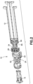
FIG. 1 is a perspective view of a syringe adapter according to one aspect of the present invention. -
FIG. 2 is a cross-sectional view of the syringe adapter ofFIG. 1 . -
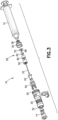
FIG. 3 is an exploded perspective view of the syringe adapter ofFIG. 1 . -
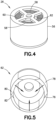
FIG. 4 is a perspective view of an aspiration assembly according to one aspect of the present invention. -
FIG. 5 is a perspective view of a one-way valve according to one aspect of the present invention. -
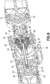
FIG. 6 is a partial cross-sectional view of the syringe adapter ofFIG. 1 , showing an aspiration flow path. -
FIG. 7 is a partial cross-sectional view of the syringe adapter ofFIG. 1 , showing a closed path through a one-way valve. -
FIG. 8 is a partial cross-sectional view of the syringe adapter ofFIG. 1 , showing a second position of a seal arrangement and highlighting a seal interface between the seal arrangement and an aspiration assembly. -
FIG. 9 is a partial cross-sectional view of the syringe adapter ofFIG. 1 , showing a second position of a seal arrangement and a flow path through the syringe adapter into a syringe. -
FIG. 10 is a cross-sectional view of an aspiration assembly according to a further aspect of the present invention. -
FIG. 11 is an exploded perspective view of the aspiration assembly ofFIG. 10 . -
FIG. 12 is a cross-sectional view of the aspiration assembly ofFIG. 10 , showing a flow path through the aspiration assembly. -
FIG. 13 is a cross-sectional view of the aspiration assembly ofFIG. 10 , showing a closed path through a one-way valve. -
FIG. 14 is a cross-sectional view of the aspiration assembly ofFIG. 10 , showing a seal arrangement in a second position. -
FIG. 15 is a cross-sectional view of the aspiration assembly ofFIG. 10 , showing a flow path through the aspiration assembly and into a connector body. -
FIG. 16 . is a cross-sectional view of the aspiration assembly ofFIG. 10 , showing a flow path arrangement and configuration pursuant to a further aspect of the present invention. -
FIG. 17 is a cross-sectional view of a seal arrangement according to one aspect of the present invention. -
FIG. 18 is a cross-sectional view of a seal arrangement according to a further aspect of the present invention. - The illustrations generally show preferred and non-limiting aspects of the systems and methods of the present disclosure. While the descriptions present various aspects of the devices, it should not be interpreted in any way as limiting the disclosure. Furthermore, modifications, concepts, and applications of the disclosure's aspects are to be interpreted by those skilled in the art as being encompassed by, but not limited to, the illustrations and descriptions herein.
- Further, for purposes of the description hereinafter, the terms "end", "upper", "lower", "right", "left", "vertical", "horizontal", "top", "bottom", "lateral", "longitudinal", and derivatives thereof shall relate to the disclosure as it is oriented in the drawing figures. The term "proximal" refers to the direction toward the center or central region of the device. The term "distal" refers to the outward direction extending away from the central region of the device. However, it is to be understood that the disclosure may assume various alternative variations and step sequences, except where expressly specified to the contrary. It is also to be understood that the specific devices and processes illustrated in the attached drawings, and described in the following specification, are simply exemplary aspects of the disclosure. Hence, specific dimensions and other physical characteristics related to the aspects disclosed herein are not to be considered as limiting. For the purpose of facilitating understanding of the disclosure, the accompanying drawings and description illustrate preferred aspects thereof, from which the disclosure, various aspects of its structures, construction and method of operation, and many advantages may be understood and appreciated.
- According to an aspect of the disclosure, a
syringe adapter 10 for connecting asyringe 12 to another medical device, such as apatient connector 14, or fluid container is provided. The medical device can be, for example, a patient line, vial adapter, fluid container, or infusion adapter. In other examples, the container can be a medical vial, syringe barrel, IV bag, or similar container for holding a fluid to be administered to a patient. Thesyringe adapter 10 can be used to facilitate closed transfer of fluids between thesyringe 12 and medical device or fluid container. - Referring to
FIGS. 1-9 , thesyringe adapter 10 according to one aspect of the present invention includes ahousing 20, acannula 22 positioned within thehousing 20, aseal arrangement 24 positioned within thehousing 20 and movable within thehousing 20 between first and second positions, and anaspiration assembly 26 positioned within thehousing 20. Theaspiration assembly 26 is configured allow thesyringe 12 to aspirate air into thesyringe 12 while thesyringe adapter 10 is connected to thesyringe 12. As noted above, in certain circumstances, aspirating air into thesyringe 12 while connected to thesyringe adapter 10 is desirable to allow air to be injected into a vial or other container. Without the aspiration arrangement, theseal arrangement 24 would prevent air from being aspirated into thesyringe 12 when connected to thesyringe adapter 10. - The
housing 20 has afirst end 30 and asecond end 32 positioned opposite thefirst end 30 and includes aconnector body 34 positioned at thefirst end 30 of thehousing 20. Theconnector body 34 is configured to be secured to thesyringe 12. In one aspect, theconnector body 34 includes afemale luer connector 36, although other suitable connection arrangements may be utilized. Thecannula 22 has afirst end 40 and asecond end 42 opposite thefirst end 40. Thecannula 22 defines atransfer opening 44 and avalve opening 46. Thetransfer opening 44 is positioned adjacent to thesecond end 42 of thecannula 22. Thevalve opening 46 is positioned intermediate the first and second ends 40, 42 of thecannula 22. Theseal arrangement 24 includes acollet 50 and amembrane 52 received within thecollet 50, although othersuitable seal arrangements 24 may be utilized. Theseal arrangement 24 has a first position with thesecond end 42 of thecannula 22 received within themembrane 52 of theseal arrangement 24 and a second position with thesecond end 42 of thecannula 22 positioned outside of themembrane 52 of theseal arrangement 24. Theseal arrangement 24 facilitates the closed transfer of fluid utilizing thesyringe adapter 10. Thecollet 50 cooperates with a mating connector, such as thepatient connector 14, to connect thecollet 50 to the mating connector and to transition theseal arrangement 24 from the first position to the second position to allow fluid to flow through thecannula 22. Theseal arrangement 24 is not discussed in detail herein and may function similarly to the seal arrangement shown and described inUnited States Patent Appl. Pub. No. 2015/0297454 . - Referring to
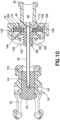
FIGS. 3-9 , theaspiration assembly 26 includes anaspiration housing 56 defining anaspiration opening 58, afilter 60 received by theaspiration housing 56, and a one-way valve 62 received by theaspiration housing 56. As shown inFIG. 6 , air is configured to flow into thefilter 60 via the aspiration opening 58, into the one-way valve 62, and into thevalve opening 46 of thecannula 22. More specifically, when asyringe plunger 64 is withdrawn, a pressure drop is created within theaspiration housing 56 to open the one-way valve 62 to aspirate air through thehousing 20, through the aspiration opening 58, through thefilter 60, through the one-way valve 62, into thecannula 22 via thevalve opening 46, through acentral passageway 65 of theconnector body 34, and into thesyringe 12. - The
aspiration assembly 26 may also include a base 66 secured to theaspiration housing 56 and engaging thefilter 60 and one-way valve 62. The base 66 may be secured to theconnector body 34. The base 66 may be secured to theaspiration housing 56 and theconnector body 34 via ultrasonic welding, although other suitable securing arrangements may also be utilized. Thefirst end 40 of thecannula 22 is secured to theconnector body 34 with thecannula 22 extending through thebase 66, the one-way valve 62, thefilter 60, and theaspiration housing 56, with thesecond end 42 of thecannula 22 configured to be received by theseal arrangement 24, as discussed above. - As shown in
FIG. 7 , the one-way valve 62 prevents the flow of fluid from the one-way valve 62 to thefilter 60 and to the aspiration opening 58 of theaspiration housing 56. As shown inFIGS. 8 and9 , themembrane 52 of theseal arrangement 24 engages and seals the aspiration opening 58 of theaspiration housing 56 when theseal arrangement 24 is in the second position. In particular, themembrane 52 of theseal arrangement 24 forms a sealedinterface 68 with theaspiration assembly 26, as highlighted inFIG. 8 , to prevent the possibility of any fluid or contamination from entering or exiting thehousing 20 via theaspiration assembly 26. A separate sealing gasket or surface may be secured to the sealingarrangement 24 rather than utilizing themembrane 52 to seal against theaspiration assembly 26. - Referring to
FIGS. 6-9 , at least a portion of theaspiration assembly 26 is received within theconnector body 34. In one aspect, thefilter 60 and one-way valve 62 are annular with the one-way valve 62 received within thefilter 60. Theaspiration housing 56 is cylindrical, although other suitable shapes and configurations may be utilized. Thebase 66 includes a planar,circular portion 70 with acylindrical extension 72 extending from the planar,circular portion 70. Thecylindrical extension 72 defines one ormore openings 74 that are in fluid communication with theaspiration housing 56. Thevalve opening 46 of thecannula 22 is positioned within thebase 66, with theopening 74 of the base 66 in fluid communication with thevalve opening 46 of thecannula 22. Thevalve opening 46 of thecannula 22 may include one ormore openings 46 as shown inFIGS. 6-9 . - Referring to
FIGS. 4-9 , the one-way valve 62 includes avalve body 76 and avalve member 78 moveable radially inward relative to thevalve body 76. Thevalve member 78 of the one-way valve 62 is elastomeric, although other suitable materials may be utilized. Thevalve member 78 may be over-molded onto thevalve body 76, although other suitable arrangements may be utilized. Thevalve member 78 includesangled surfaces 80 that cooperate with correspondingangled surfaces 82 of thevalve body 76 to only allow radially inward movement of thevalve member 78. Accordingly, the one-way valve 62 only permits aspiration of air into the one-way valve 62 (FIG. 6 ) and into theaspiration assembly 26 with air moving from thesyringe 12 into the aspiration assembly 26 (FIG. 7 ) causing theangled surfaces 80 of thevalve member 78 to engage and seal against theangled surfaces 82 of thevalve body 76 hereby preventing flow through the one-way valve 62. Due to the positioning of the one-way valve 62 within thefilter 60, thefilter 60 is also configured to prevent thevalve member 78 from moving radially outward. In other words, thefilter 60 restricts any radially outward movement of thevalve member 78. During aspiration into thesyringe 12, thefilter 60 is configured to filter any contamination from the air as the air is aspirated into thesyringe 12 through theaspiration assembly 26. Thefilter 60 may be hydrophobic and/or oleophobic. - Referring to
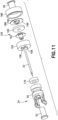
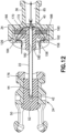
FIGS. 10-18 , anaspiration assembly 126 according to a further aspect of the present invention is provided. Theaspiration assembly 126 is similar to theaspiration assembly 26 ofFIGS. 1-9 and functions in a similar manner. Theaspiration assembly 126 is incorporated within a syringe adapter in a similar manner as theaspiration assembly 26 ofFIGS. 1-9 . Theaspiration assembly 126 ofFIGS. 10-18 includes anaspiration housing 156 defining anaspiration opening 158, afilter 160 received by theaspiration housing 156, and a one-way valve 162 received by theaspiration housing 156, where air is configured to flow into theaspiration housing 156 via the aspiration opening 158, through the one-way valve 162, and through thefilter 160. Theaspiration assembly 126 includes a base 166 secured to theaspiration housing 156 and engaging thefilter 160. Rather than providing thevalve opening 46 in thecannula 22 as in thesyringe adapter 10 ofFIGS. 1-9 , thebase 166 defines anopening 170 and theconnector body 34 defines anopening 172. Theopening 172 of theconnector body 34 is in fluid communication with theopening 170 of thebase 166 and thecentral passageway 65 of theconnector body 34. Accordingly, as shown inFIG. 12 , a flow path is provided through the aspiration opening 158 of theaspiration housing 156, past the one-way valve 162, through thefilter 160, through theopening 170 in thebase 166, through theopening 172 of theconnector body 34, and into thecentral passageway 65 of theconnector body 34. - Referring to
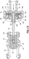
FIGS. 12-18 , thefirst end 40 of thecannula 22 is secured to theconnector body 34, with thecannula 22 extending through thefilter 160, the one-way valve 162, and theaspiration housing 158 with thesecond end 42 of thecannula 22 configured to be received by theseal arrangement 24. The one-way valve 162 prevents the flow of fluid from within theaspiration housing 156 to theaspiration opening 158. As with thesyringe adapter 10 discussed above in connection withFIGS. 1-9 , theseal arrangement 24 engages and seals the aspiration opening 158 of theaspiration housing 156 when theseal arrangement 24 is in the second position. Themembrane 52 of theseal arrangement 24 may engage and seal the aspiration opening 158 as shown inFIGS. 14 and17 . Alternatively, in a further aspect shown inFIG. 18 , a sealinggasket 176 is received by thecollet 50 with the sealinggasket 176 engaging and sealing the aspiration opening 158 of theaspiration housing 156. The one-way valve 162 is an umbrella valve, although other suitable arrangements may be provided. The one-way valve 162 includes acentral body 180 defining apassageway 182 and an umbrella-shapedflange 184 extending from thecentral body 180. As shown inFIG. 12 , the umbrella-shapedflange 184 is resilient and configured to lift away from the aspiration opening 158 of theaspiration housing 156 when air is aspirated via thesyringe 12 through the aspiration opening 158 towards the opening 170 in thebase 166 and theopening 172 in theconnector body 34. In particular, withdrawing theplunger 64 of thesyringe 12 will cause a pressure drop within theaspiration housing 156, which opens the one-way valve 162 and draws in air via the aspiration opening 158 as discussed above. As shown inFIGS. 13 and14 , air or fluid flowing through thecentral passageway 65 of theconnector body 34, into theopening 172 of theconnector body 34, into theopening 170 of thebase 166, and into theaspiration housing 156 will force the umbrella-shapedflange 184 of the one-way valve 162 against theaspiration housing 156 to block theaspiration opening 158. Although a plurality ofaspiration openings 158 are shown, one ormore aspiration openings 158 may be provided. During aspiration, thefilter 160 will filter any contamination passing through theaspiration housing 156 to theconnector body 34. Thefilter 160 may be hydrophobic and/or oleophobic. - The
aspiration housing 156 is cylindrical, although other suitable shapes and configurations may be utilized. Thebase 166 includes a planar,circular portion 188 with acylindrical extension 190 extending from the planar,circular portion 188. Thefilter 160 is annular and positioned over thecylindrical extension 190 of thebase 166. Thecylindrical extension 190 of the base 166 also extends through thepassageway 182 of thecentral body 180 of the one-way valve 162. A portion of the one-way valve 162 and the base 166 extend from theaspiration housing 156, although other suitable arrangements may be utilized. - Referring to
FIG. 16 , rather than providing the base 166 as shown inFIG. 15 , theconnector body 34 may be provided with acylindrical extension 194 that extends through thefilter 160, the one-way valve 162, and theaspiration housing 156. Theopening 172 of theconnector body 34 is directly in fluid communication with theaspiration housing 156 with a fluid path formed through the aspiration opening 158, past the one-way valve 162, into theaspiration housing 156, through thefilter 160, into theopening 172 of theconnector body 34, which leads to thecentral passageway 65 of theconnector body 34.
Claims (10)
- A syringe adapter (10) comprising:a housing (20) having a first end (30) and a second end (32) positioned opposite the first end (30), the housing (20) including a connector body (34) positioned at the first end (30) of the housing (20) and configured to be secured to a syringe barrel;a cannula (22) positioned within the housing (20), the cannula (22) having a first end (40) and a second end (42) opposite the first end (40), the cannula (22) defining a transfer opening (44) and a valve opening (46);a seal arrangement (24) positioned within the housing (20) and movable within the housing (20), the seal arrangement (24) comprising a membrane (52); and characterized inan aspiration assembly (26) positioned within the housing (20) comprising:an aspiration housing (56) defining an aspiration opening (58);a filter (60) received by the aspiration housing (56); anda one-way valve (62) received by the aspiration housing (56), wherein the valve opening (46) of the cannula (22) is positioned within the aspiration housing (56), wherein air is configured to flow into the filter (60) via the aspiration opening (58), into the one-way valve (62), and into the valve opening (46) of the cannula (22), andwherein the seal arrangement (24) has a first position with the second end (42) of the cannula (22) received within the membrane (52) of the seal arrangement (24) and a second position with the second end (42) of the cannula (22) positioned outside of the membrane (52) of the seal arrangement (24), the membrane (52) of the seal arrangement (24) engaging and sealing the aspiration opening (58) of the aspiration housing (56) when the seal arrangement (24) is in the second position.
- The syringe adapter (10) of claim 1, wherein the aspiration assembly (26) further comprises a base (66) secured to the aspiration housing (56) and engaging the filter (60) and the one-way valve (62).
- The syringe adapter (10) of claim 2, wherein the base (66) is secured to the connector body (34).
- The syringe adapter (10) of claim 2, wherein the first end (40) of the cannula (22) is secured to the connector body (34), the cannula (22) extending through the base (66), the one-way valve (62), the filter (60), and the aspiration housing (56) with the second end (42) of the cannula (22) configured to be received by the seal arrangement (24).
- The syringe adapter (10) of claim 1, wherein the one-way valve (62) prevents the flow of fluid from the one-way valve (62) to the filter (60) and to the aspiration opening (58) of the aspiration housing (56).
- The syringe adapter (10) of claim 1, wherein at least a portion of the aspiration assembly (26) is received within the connector body (34).
- The syringe adapter (10) of claim 1, wherein the valve opening (46) of the cannula (22) comprises a plurality of openings.
- The syringe adapter (10) of claim 1, wherein the filter (60) and the one-way valve (62) are annular, and wherein the one-way valve (62) is received within the filter (60).
- The syringe adapter (10) of claim 1, wherein the one-way valve (62) comprises a valve body (76) and a valve member (78) moveable radially inward relative to the valve body (76).
- The syringe adapter of claim 1, wherein the valve member (78) of the one-way valve (62) is elastomeric.
Priority Applications (1)
| Application Number | Priority Date | Filing Date | Title |
|---|---|---|---|
| EP23212490.9A EP4324445A3 (en) | 2018-04-19 | 2019-04-11 | Syringe adapter with aspiration assembly |
Applications Claiming Priority (2)
| Application Number | Priority Date | Filing Date | Title |
|---|---|---|---|
| US201862659840P | 2018-04-19 | 2018-04-19 | |
| PCT/US2019/026946 WO2019204111A1 (en) | 2018-04-19 | 2019-04-11 | Syringe adapter with aspiration assembly |
Related Child Applications (2)
| Application Number | Title | Priority Date | Filing Date |
|---|---|---|---|
| EP23212490.9A Division EP4324445A3 (en) | 2018-04-19 | 2019-04-11 | Syringe adapter with aspiration assembly |
| EP23212490.9A Division-Into EP4324445A3 (en) | 2018-04-19 | 2019-04-11 | Syringe adapter with aspiration assembly |
Publications (3)
| Publication Number | Publication Date |
|---|---|
| EP3781237A1 EP3781237A1 (en) | 2021-02-24 |
| EP3781237B1 true EP3781237B1 (en) | 2024-01-03 |
| EP3781237C0 EP3781237C0 (en) | 2024-01-03 |
Family
ID=66248875
Family Applications (2)
| Application Number | Title | Priority Date | Filing Date |
|---|---|---|---|
| EP19719145.5A Active EP3781237B1 (en) | 2018-04-19 | 2019-04-11 | Syringe adapter with aspiration assembly |
| EP23212490.9A Pending EP4324445A3 (en) | 2018-04-19 | 2019-04-11 | Syringe adapter with aspiration assembly |
Family Applications After (1)
| Application Number | Title | Priority Date | Filing Date |
|---|---|---|---|
| EP23212490.9A Pending EP4324445A3 (en) | 2018-04-19 | 2019-04-11 | Syringe adapter with aspiration assembly |
Country Status (9)
| Country | Link |
|---|---|
| US (3) | US11311459B2 (en) |
| EP (2) | EP3781237B1 (en) |
| JP (3) | JP7068497B2 (en) |
| CN (2) | CN112165965B (en) |
| AU (2) | AU2019257279B2 (en) |
| CA (1) | CA3097126C (en) |
| ES (1) | ES2973081T3 (en) |
| MX (1) | MX2020011047A (en) |
| WO (1) | WO2019204111A1 (en) |
Families Citing this family (10)
| Publication number | Priority date | Publication date | Assignee | Title |
|---|---|---|---|---|
| JP7068497B2 (en) * | 2018-04-19 | 2022-05-16 | ベクトン ディキンソン アンド カンパニー リミテッド | Syringe adapter with suction assembly |
| US11865076B2 (en) * | 2019-11-22 | 2024-01-09 | Aktivax, Inc. | Closed system for transferring medication from a flexible container |
| DE102020202941A1 (en) | 2020-03-06 | 2021-09-09 | B. Braun Melsungen Aktiengesellschaft | Coupling element and coupling system for a closed fluid transfer system |
| DE102020202935A1 (en) | 2020-03-06 | 2021-09-09 | B. Braun Melsungen Aktiengesellschaft | Coupling element for a closed fluid transfer system, mating coupling element for such a coupling element and coupling system |
| DE102020202939A1 (en) | 2020-03-06 | 2021-09-09 | B. Braun Melsungen Aktiengesellschaft | Coupling element for a closed fluid transfer system, mating coupling element for such a coupling element and coupling system |
| DE102020203153A1 (en) | 2020-03-11 | 2021-09-16 | B. Braun Melsungen Aktiengesellschaft | Coupling element for a closed fluid transfer system, attachment for such a coupling element, coupling system and coupling kit |
| DE102020210629A1 (en) * | 2020-08-20 | 2022-02-24 | B. Braun Melsungen Aktiengesellschaft | Filter system for a closed fluid transfer system with pressure equalization |
| CN112890813B (en) * | 2021-02-23 | 2022-12-06 | 河北医科大学第一医院 | arterial blood collection needle |
| CN116687513A (en) * | 2023-07-04 | 2023-09-05 | 上海市肺科医院(上海市职业病防治院) | Valves and thrombus aspiration devices |
| WO2025008457A1 (en) * | 2023-07-04 | 2025-01-09 | Fresenius Kabi Deutschland Gmbh | Air injector for an infusion system |
Family Cites Families (17)
| Publication number | Priority date | Publication date | Assignee | Title |
|---|---|---|---|---|
| IT1173370B (en) * | 1984-02-24 | 1987-06-24 | Erba Farmitalia | SAFETY DEVICE TO CONNECT A SYRINGE TO THE MOUTH OF A BOTTLE CONTAINING A DRUG OR A TUBE FOR DISPENSING THE SYRINGE DRUG |
| US7134641B2 (en) | 2004-10-21 | 2006-11-14 | International Engine Intellectual Property Company, Llc | Valve having axial and radial passages |
| CN102784058B (en) | 2007-04-23 | 2014-12-17 | 普拉斯特米德有限公司 | Method and apparatus for contamination-free transfer of a hazardous drug |
| CN101288786A (en) | 2008-06-19 | 2008-10-22 | 李英 | Disposable air-intake installation of infusion device |
| US8454579B2 (en) | 2009-03-25 | 2013-06-04 | Icu Medical, Inc. | Medical connector with automatic valves and volume regulator |
| EP2589367A4 (en) * | 2010-06-30 | 2014-09-03 | Terumo Corp | Connector and connector assembly |
| WO2012008285A1 (en) * | 2010-07-12 | 2012-01-19 | 株式会社ジェイ・エム・エス | Drug solution delivery device for medical use |
| US9597260B2 (en) * | 2013-03-15 | 2017-03-21 | Becton Dickinson and Company Ltd. | System for closed transfer of fluids |
| US9414990B2 (en) * | 2013-03-15 | 2016-08-16 | Becton Dickinson and Company Ltd. | Seal system for cannula |
| CN107252523B (en) * | 2013-03-15 | 2020-09-22 | 贝克顿·迪金森有限公司 | Cannula Sealing System |
| US10813837B2 (en) * | 2014-03-05 | 2020-10-27 | Yukon Medical, Llc | Pre-filled diluent syringe vial adapter |
| CN106470657B (en) | 2014-04-21 | 2020-03-17 | 贝克顿迪金森有限公司 | System for closed transfer of fluids |
| AU2015249947B9 (en) * | 2014-04-21 | 2017-11-30 | Becton Dickinson and Company Limited | System for closed transfer of fluids and membrane arrangements for use thereof |
| IL237788B (en) * | 2015-03-16 | 2019-10-31 | Kriheli Marino | Septum holders for use in syringe connectors |
| KR101572663B1 (en) * | 2015-05-20 | 2015-11-27 | (주)상아프론테크 | Filter structure for syringe and syringe having the same |
| AU2016276956B2 (en) * | 2015-06-12 | 2018-08-09 | Becton Dickinson and Company Limited | Syringe adapter with spinning connector |
| JP7068497B2 (en) * | 2018-04-19 | 2022-05-16 | ベクトン ディキンソン アンド カンパニー リミテッド | Syringe adapter with suction assembly |
-
2019
- 2019-04-11 JP JP2020557957A patent/JP7068497B2/en active Active
- 2019-04-11 CN CN201980034887.7A patent/CN112165965B/en active Active
- 2019-04-11 CN CN202211142453.9A patent/CN115475308B/en active Active
- 2019-04-11 ES ES19719145T patent/ES2973081T3/en active Active
- 2019-04-11 US US16/381,464 patent/US11311459B2/en active Active
- 2019-04-11 EP EP19719145.5A patent/EP3781237B1/en active Active
- 2019-04-11 CA CA3097126A patent/CA3097126C/en active Active
- 2019-04-11 AU AU2019257279A patent/AU2019257279B2/en active Active
- 2019-04-11 WO PCT/US2019/026946 patent/WO2019204111A1/en not_active Ceased
- 2019-04-11 MX MX2020011047A patent/MX2020011047A/en unknown
- 2019-04-11 EP EP23212490.9A patent/EP4324445A3/en active Pending
-
2022
- 2022-02-15 US US17/672,399 patent/US11806309B2/en active Active
- 2022-04-28 JP JP2022074609A patent/JP7442568B2/en active Active
- 2022-06-28 AU AU2022204547A patent/AU2022204547B2/en active Active
-
2023
- 2023-10-03 US US18/376,107 patent/US20240024201A1/en active Pending
- 2023-12-08 JP JP2023207757A patent/JP7807422B2/en active Active
Also Published As
| Publication number | Publication date |
|---|---|
| EP4324445A2 (en) | 2024-02-21 |
| AU2019257279B2 (en) | 2022-03-31 |
| CN112165965A (en) | 2021-01-01 |
| JP7807422B2 (en) | 2026-01-27 |
| JP2024015299A (en) | 2024-02-01 |
| AU2022204547B2 (en) | 2023-11-16 |
| WO2019204111A1 (en) | 2019-10-24 |
| US20190321261A1 (en) | 2019-10-24 |
| AU2022204547A1 (en) | 2022-07-21 |
| CA3097126A1 (en) | 2019-10-24 |
| EP3781237A1 (en) | 2021-02-24 |
| AU2019257279A1 (en) | 2020-12-03 |
| US20240024201A1 (en) | 2024-01-25 |
| JP2022093563A (en) | 2022-06-23 |
| JP7442568B2 (en) | 2024-03-04 |
| US11806309B2 (en) | 2023-11-07 |
| JP2021521929A (en) | 2021-08-30 |
| ES2973081T3 (en) | 2024-06-18 |
| CN115475308B (en) | 2024-12-03 |
| US11311459B2 (en) | 2022-04-26 |
| JP7068497B2 (en) | 2022-05-16 |
| EP4324445A3 (en) | 2024-05-22 |
| EP3781237C0 (en) | 2024-01-03 |
| CN115475308A (en) | 2022-12-16 |
| US20220168186A1 (en) | 2022-06-02 |
| MX2020011047A (en) | 2021-01-15 |
| CA3097126C (en) | 2022-11-29 |
| CN112165965B (en) | 2022-10-14 |
Similar Documents
| Publication | Publication Date | Title |
|---|---|---|
| AU2022204547B2 (en) | Syringe adapter with aspiration assembly | |
| US11559633B2 (en) | Syringe adapter with spinning connector | |
| US12383466B2 (en) | Fluid transfer device and packaging therefor | |
| US9833605B2 (en) | Fluid transfer device and packaging therefor | |
| AU2019238179B2 (en) | Connection arrangement for closed system transfer of fluids | |
| AU2022201951B2 (en) | Syringe adapter with secure connection |
Legal Events
| Date | Code | Title | Description |
|---|---|---|---|
| STAA | Information on the status of an ep patent application or granted ep patent |
Free format text: STATUS: UNKNOWN |
|
| STAA | Information on the status of an ep patent application or granted ep patent |
Free format text: STATUS: THE INTERNATIONAL PUBLICATION HAS BEEN MADE |
|
| PUAI | Public reference made under article 153(3) epc to a published international application that has entered the european phase |
Free format text: ORIGINAL CODE: 0009012 |
|
| STAA | Information on the status of an ep patent application or granted ep patent |
Free format text: STATUS: REQUEST FOR EXAMINATION WAS MADE |
|
| 17P | Request for examination filed |
Effective date: 20201113 |
|
| AK | Designated contracting states |
Kind code of ref document: A1 Designated state(s): AL AT BE BG CH CY CZ DE DK EE ES FI FR GB GR HR HU IE IS IT LI LT LU LV MC MK MT NL NO PL PT RO RS SE SI SK SM TR |
|
| AX | Request for extension of the european patent |
Extension state: BA ME |
|
| RIN1 | Information on inventor provided before grant (corrected) |
Inventor name: OSHINSKI, MATTHEW Inventor name: RIGHEZ MESQUITA, ANTONIO |
|
| DAV | Request for validation of the european patent (deleted) | ||
| DAX | Request for extension of the european patent (deleted) | ||
| GRAP | Despatch of communication of intention to grant a patent |
Free format text: ORIGINAL CODE: EPIDOSNIGR1 |
|
| STAA | Information on the status of an ep patent application or granted ep patent |
Free format text: STATUS: GRANT OF PATENT IS INTENDED |
|
| INTG | Intention to grant announced |
Effective date: 20230807 |
|
| RIN1 | Information on inventor provided before grant (corrected) |
Inventor name: OSHINSKI, MATTHEW Inventor name: RIGHEZ MESQUITA, ANTONIO |
|
| GRAS | Grant fee paid |
Free format text: ORIGINAL CODE: EPIDOSNIGR3 |
|
| GRAA | (expected) grant |
Free format text: ORIGINAL CODE: 0009210 |
|
| STAA | Information on the status of an ep patent application or granted ep patent |
Free format text: STATUS: THE PATENT HAS BEEN GRANTED |
|
| AK | Designated contracting states |
Kind code of ref document: B1 Designated state(s): AL AT BE BG CH CY CZ DE DK EE ES FI FR GB GR HR HU IE IS IT LI LT LU LV MC MK MT NL NO PL PT RO RS SE SI SK SM TR |
|
| REG | Reference to a national code |
Ref country code: GB Ref legal event code: FG4D |
|
| REG | Reference to a national code |
Ref country code: CH Ref legal event code: EP |
|
| REG | Reference to a national code |
Ref country code: DE Ref legal event code: R096 Ref document number: 602019044418 Country of ref document: DE |
|
| REG | Reference to a national code |
Ref country code: IE Ref legal event code: FG4D |
|
| U01 | Request for unitary effect filed |
Effective date: 20240104 |
|
| U07 | Unitary effect registered |
Designated state(s): AT BE BG DE DK EE FI FR IT LT LU LV MT NL PT SE SI Effective date: 20240115 |
|
| U20 | Renewal fee for the european patent with unitary effect paid |
Year of fee payment: 6 Effective date: 20240320 |
|
| REG | Reference to a national code |
Ref country code: ES Ref legal event code: FG2A Ref document number: 2973081 Country of ref document: ES Kind code of ref document: T3 Effective date: 20240618 |
|
| PG25 | Lapsed in a contracting state [announced via postgrant information from national office to epo] |
Ref country code: IS Free format text: LAPSE BECAUSE OF FAILURE TO SUBMIT A TRANSLATION OF THE DESCRIPTION OR TO PAY THE FEE WITHIN THE PRESCRIBED TIME-LIMIT Effective date: 20240503 |
|
| PG25 | Lapsed in a contracting state [announced via postgrant information from national office to epo] |
Ref country code: GR Free format text: LAPSE BECAUSE OF FAILURE TO SUBMIT A TRANSLATION OF THE DESCRIPTION OR TO PAY THE FEE WITHIN THE PRESCRIBED TIME-LIMIT Effective date: 20240404 |
|
| PG25 | Lapsed in a contracting state [announced via postgrant information from national office to epo] |
Ref country code: HR Free format text: LAPSE BECAUSE OF FAILURE TO SUBMIT A TRANSLATION OF THE DESCRIPTION OR TO PAY THE FEE WITHIN THE PRESCRIBED TIME-LIMIT Effective date: 20240103 Ref country code: RS Free format text: LAPSE BECAUSE OF FAILURE TO SUBMIT A TRANSLATION OF THE DESCRIPTION OR TO PAY THE FEE WITHIN THE PRESCRIBED TIME-LIMIT Effective date: 20240403 |
|
| PG25 | Lapsed in a contracting state [announced via postgrant information from national office to epo] |
Ref country code: CZ Free format text: LAPSE BECAUSE OF FAILURE TO SUBMIT A TRANSLATION OF THE DESCRIPTION OR TO PAY THE FEE WITHIN THE PRESCRIBED TIME-LIMIT Effective date: 20240103 |
|
| PG25 | Lapsed in a contracting state [announced via postgrant information from national office to epo] |
Ref country code: RS Free format text: LAPSE BECAUSE OF FAILURE TO SUBMIT A TRANSLATION OF THE DESCRIPTION OR TO PAY THE FEE WITHIN THE PRESCRIBED TIME-LIMIT Effective date: 20240403 Ref country code: NO Free format text: LAPSE BECAUSE OF FAILURE TO SUBMIT A TRANSLATION OF THE DESCRIPTION OR TO PAY THE FEE WITHIN THE PRESCRIBED TIME-LIMIT Effective date: 20240403 Ref country code: IS Free format text: LAPSE BECAUSE OF FAILURE TO SUBMIT A TRANSLATION OF THE DESCRIPTION OR TO PAY THE FEE WITHIN THE PRESCRIBED TIME-LIMIT Effective date: 20240503 Ref country code: HR Free format text: LAPSE BECAUSE OF FAILURE TO SUBMIT A TRANSLATION OF THE DESCRIPTION OR TO PAY THE FEE WITHIN THE PRESCRIBED TIME-LIMIT Effective date: 20240103 Ref country code: GR Free format text: LAPSE BECAUSE OF FAILURE TO SUBMIT A TRANSLATION OF THE DESCRIPTION OR TO PAY THE FEE WITHIN THE PRESCRIBED TIME-LIMIT Effective date: 20240404 Ref country code: CZ Free format text: LAPSE BECAUSE OF FAILURE TO SUBMIT A TRANSLATION OF THE DESCRIPTION OR TO PAY THE FEE WITHIN THE PRESCRIBED TIME-LIMIT Effective date: 20240103 |
|
| PG25 | Lapsed in a contracting state [announced via postgrant information from national office to epo] |
Ref country code: PL Free format text: LAPSE BECAUSE OF FAILURE TO SUBMIT A TRANSLATION OF THE DESCRIPTION OR TO PAY THE FEE WITHIN THE PRESCRIBED TIME-LIMIT Effective date: 20240103 |
|
| PG25 | Lapsed in a contracting state [announced via postgrant information from national office to epo] |
Ref country code: PL Free format text: LAPSE BECAUSE OF FAILURE TO SUBMIT A TRANSLATION OF THE DESCRIPTION OR TO PAY THE FEE WITHIN THE PRESCRIBED TIME-LIMIT Effective date: 20240103 |
|
| REG | Reference to a national code |
Ref country code: DE Ref legal event code: R097 Ref document number: 602019044418 Country of ref document: DE |
|
| PG25 | Lapsed in a contracting state [announced via postgrant information from national office to epo] |
Ref country code: SM Free format text: LAPSE BECAUSE OF FAILURE TO SUBMIT A TRANSLATION OF THE DESCRIPTION OR TO PAY THE FEE WITHIN THE PRESCRIBED TIME-LIMIT Effective date: 20240103 |
|
| PG25 | Lapsed in a contracting state [announced via postgrant information from national office to epo] |
Ref country code: SK Free format text: LAPSE BECAUSE OF FAILURE TO SUBMIT A TRANSLATION OF THE DESCRIPTION OR TO PAY THE FEE WITHIN THE PRESCRIBED TIME-LIMIT Effective date: 20240103 |
|
| PG25 | Lapsed in a contracting state [announced via postgrant information from national office to epo] |
Ref country code: SM Free format text: LAPSE BECAUSE OF FAILURE TO SUBMIT A TRANSLATION OF THE DESCRIPTION OR TO PAY THE FEE WITHIN THE PRESCRIBED TIME-LIMIT Effective date: 20240103 Ref country code: SK Free format text: LAPSE BECAUSE OF FAILURE TO SUBMIT A TRANSLATION OF THE DESCRIPTION OR TO PAY THE FEE WITHIN THE PRESCRIBED TIME-LIMIT Effective date: 20240103 Ref country code: RO Free format text: LAPSE BECAUSE OF FAILURE TO SUBMIT A TRANSLATION OF THE DESCRIPTION OR TO PAY THE FEE WITHIN THE PRESCRIBED TIME-LIMIT Effective date: 20240103 |
|
| PLBE | No opposition filed within time limit |
Free format text: ORIGINAL CODE: 0009261 |
|
| STAA | Information on the status of an ep patent application or granted ep patent |
Free format text: STATUS: NO OPPOSITION FILED WITHIN TIME LIMIT |
|
| PG25 | Lapsed in a contracting state [announced via postgrant information from national office to epo] |
Ref country code: MC Free format text: LAPSE BECAUSE OF FAILURE TO SUBMIT A TRANSLATION OF THE DESCRIPTION OR TO PAY THE FEE WITHIN THE PRESCRIBED TIME-LIMIT Effective date: 20240103 |
|
| PG25 | Lapsed in a contracting state [announced via postgrant information from national office to epo] |
Ref country code: MC Free format text: LAPSE BECAUSE OF FAILURE TO SUBMIT A TRANSLATION OF THE DESCRIPTION OR TO PAY THE FEE WITHIN THE PRESCRIBED TIME-LIMIT Effective date: 20240103 |
|
| REG | Reference to a national code |
Ref country code: CH Ref legal event code: PL |
|
| 26N | No opposition filed |
Effective date: 20241007 |
|
| PG25 | Lapsed in a contracting state [announced via postgrant information from national office to epo] |
Ref country code: CH Free format text: LAPSE BECAUSE OF NON-PAYMENT OF DUE FEES Effective date: 20240430 |
|
| PG25 | Lapsed in a contracting state [announced via postgrant information from national office to epo] |
Ref country code: IE Free format text: LAPSE BECAUSE OF NON-PAYMENT OF DUE FEES Effective date: 20240411 |
|
| U20 | Renewal fee for the european patent with unitary effect paid |
Year of fee payment: 7 Effective date: 20250319 |
|
| PGFP | Annual fee paid to national office [announced via postgrant information from national office to epo] |
Ref country code: ES Payment date: 20250502 Year of fee payment: 7 |
|
| PG25 | Lapsed in a contracting state [announced via postgrant information from national office to epo] |
Ref country code: CY Free format text: LAPSE BECAUSE OF FAILURE TO SUBMIT A TRANSLATION OF THE DESCRIPTION OR TO PAY THE FEE WITHIN THE PRESCRIBED TIME-LIMIT; INVALID AB INITIO Effective date: 20190411 |
|
| PG25 | Lapsed in a contracting state [announced via postgrant information from national office to epo] |
Ref country code: HU Free format text: LAPSE BECAUSE OF FAILURE TO SUBMIT A TRANSLATION OF THE DESCRIPTION OR TO PAY THE FEE WITHIN THE PRESCRIBED TIME-LIMIT; INVALID AB INITIO Effective date: 20190411 |
|
| PGFP | Annual fee paid to national office [announced via postgrant information from national office to epo] |
Ref country code: GB Payment date: 20260319 Year of fee payment: 8 |
|
| U20 | Renewal fee for the european patent with unitary effect paid |
Year of fee payment: 8 Effective date: 20260319 |