EP3780840B1 - Drahtlose betriebsmittelplanung - Google Patents
Drahtlose betriebsmittelplanung Download PDFInfo
- Publication number
- EP3780840B1 EP3780840B1 EP19778053.9A EP19778053A EP3780840B1 EP 3780840 B1 EP3780840 B1 EP 3780840B1 EP 19778053 A EP19778053 A EP 19778053A EP 3780840 B1 EP3780840 B1 EP 3780840B1
- Authority
- EP
- European Patent Office
- Prior art keywords
- length
- transmission
- time unit
- parameter value
- channel
- Prior art date
- Legal status (The legal status is an assumption and is not a legal conclusion. Google has not performed a legal analysis and makes no representation as to the accuracy of the status listed.)
- Active
Links
Images


Classifications
-
- H—ELECTRICITY
- H04—ELECTRIC COMMUNICATION TECHNIQUE
- H04L—TRANSMISSION OF DIGITAL INFORMATION, e.g. TELEGRAPHIC COMMUNICATION
- H04L5/00—Arrangements affording multiple use of the transmission path
- H04L5/14—Two-way operation using the same type of signal, i.e. duplex
- H04L5/1469—Two-way operation using the same type of signal, i.e. duplex using time-sharing
-
- H—ELECTRICITY
- H04—ELECTRIC COMMUNICATION TECHNIQUE
- H04W—WIRELESS COMMUNICATION NETWORKS
- H04W72/00—Local resource management
- H04W72/20—Control channels or signalling for resource management
- H04W72/21—Control channels or signalling for resource management in the uplink direction of a wireless link, i.e. towards the network
-
- H—ELECTRICITY
- H04—ELECTRIC COMMUNICATION TECHNIQUE
- H04L—TRANSMISSION OF DIGITAL INFORMATION, e.g. TELEGRAPHIC COMMUNICATION
- H04L5/00—Arrangements affording multiple use of the transmission path
- H04L5/003—Arrangements for allocating sub-channels of the transmission path
- H04L5/0048—Allocation of pilot signals, i.e. of signals known to the receiver
-
- H—ELECTRICITY
- H04—ELECTRIC COMMUNICATION TECHNIQUE
- H04L—TRANSMISSION OF DIGITAL INFORMATION, e.g. TELEGRAPHIC COMMUNICATION
- H04L5/00—Arrangements affording multiple use of the transmission path
- H04L5/003—Arrangements for allocating sub-channels of the transmission path
- H04L5/0078—Timing of allocation
- H04L5/0082—Timing of allocation at predetermined intervals
-
- H—ELECTRICITY
- H04—ELECTRIC COMMUNICATION TECHNIQUE
- H04L—TRANSMISSION OF DIGITAL INFORMATION, e.g. TELEGRAPHIC COMMUNICATION
- H04L5/00—Arrangements affording multiple use of the transmission path
- H04L5/0091—Signalling for the administration of the divided path, e.g. signalling of configuration information
- H04L5/0092—Indication of how the channel is divided
-
- H—ELECTRICITY
- H04—ELECTRIC COMMUNICATION TECHNIQUE
- H04W—WIRELESS COMMUNICATION NETWORKS
- H04W72/00—Local resource management
- H04W72/20—Control channels or signalling for resource management
- H04W72/23—Control channels or signalling for resource management in the downlink direction of a wireless link, i.e. towards a terminal
-
- H—ELECTRICITY
- H04—ELECTRIC COMMUNICATION TECHNIQUE
- H04L—TRANSMISSION OF DIGITAL INFORMATION, e.g. TELEGRAPHIC COMMUNICATION
- H04L5/00—Arrangements affording multiple use of the transmission path
- H04L5/0001—Arrangements for dividing the transmission path
- H04L5/0003—Two-dimensional division
- H04L5/0005—Time-frequency
- H04L5/0007—Time-frequency the frequencies being orthogonal, e.g. OFDM(A) or DMT
-
- H—ELECTRICITY
- H04—ELECTRIC COMMUNICATION TECHNIQUE
- H04L—TRANSMISSION OF DIGITAL INFORMATION, e.g. TELEGRAPHIC COMMUNICATION
- H04L5/00—Arrangements affording multiple use of the transmission path
- H04L5/003—Arrangements for allocating sub-channels of the transmission path
- H04L5/0044—Allocation of payload; Allocation of data channels, e.g. PDSCH or PUSCH
Definitions
- the present application relates to a wireless resource scheduling method, a network side equipment, and a UE.
- LTE long term evolution
- UE user equipment
- TDD time division duplexing
- the base station During the communication between the base station and the UE, the base station indicates the configured TDD frame structure to the UE in the cell, and communicates with the UE based on the configured TDD frame structure.
- WO 2016/074250A1 provides a resource scheduling method, a resource determining method, an eNB, and a user equipment.
- CATT "Simultaneous PUCCH-PUSCH transmission in NR”
- 3GPP DRAFT R1-1712408
- provides simultaneous PUCCH-PUSCH transmission in NR and specifically discuss the UCI and data/SRS multiplexing for both short duration PUCCH format and long duration PUCCH format.
- WO 2018/031623A1 provides an apparatus of a New Radio (NR) NodeB (gNB) comprises one or more baseband processors to configure a physical downlink control channel (PDCCH) for the transmission of data to a user equipment (UE) in a physical downlink shared channel (PDSCH).
- NR New Radio
- gNB comprises one or more baseband processors to configure a physical downlink control channel (PDCCH) for the transmission of data to a user equipment (UE) in a physical downlink shared channel (PDSCH).
- PDCCH physical downlink control channel
- UE user equipment
- PDSCH physical downlink shared channel
- the network side equipment and the UE may agree and set it as default that transmission on the PUCCH also exists, after the transmission time lengths in the number of the first parameter value elapse, and the transmission length type may be the short type.
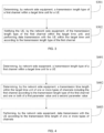
- FIG. 7 is a flowchart of the wireless resource scheduling method provided in another example of the present disclosure.
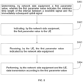
- the resource scheduling method comprises: At block S701a: determining, by a network side equipment, a value set of first parameters, and then sending the value set to UE; wherein a first parameter is a parameter for indicating a minimum time length of an interval between a downlink signal and the immediately subsequent uplink signal.
- the network side equipment determining the value set of first parameters may refer to receiving a value set input by a network administrator, that is, the value set of first parameters may be preset empirically.
- the network side equipment may also determine the value set of first parameters based on a cell coverage distance and the counted processing time of each UE in the cell, and send the same to the UEs in the cell concurrently.
- the processing time of each UE includes at least one of the following: time required for receiving and decoding a downlink channel, time required for generating an uplink sending signal, and time required for switching from downlink receiving to uplink sending.
- the network side equipment selects one value for the UE from the value set of first parameters based on the cell coverage distance and the processing time of the UE.
- the UE here may be one UE, a group of UEs, or all the UEs within a cell.
- the network side equipment may select a first parameter value for the group of UEs or the UEs within the cell based on the processing time of the UE with the lowest processing capability among the group of UEs or the UEs within the cell.
- a first parameter value may be selected for the group of UEs from the value set of first parameters, based on the cell coverage distance and the processing time of the UE with the lowest processing capability in the group of UEs. If different UEs or different groups of UEs vary greatly in processing capability, the network side equipment may select a first parameter value from the value set of first parameters for each UE or each group of UEs separately.
- the network side equipment sends the first bit identifier to the above-described one UE, one group of UEs or UEs within the cell, and the one UE, one group of UEs or UEs within the cell determine(s) the first parameter value from the value set of first parameters based on the first bit identifier, as detailed in S704a.
- the decimal value set of first parameters is ⁇ 1, 4, 7, 11 ⁇
- the corresponding binary bit identifier set is ⁇ 00, 01, 10, 11 ⁇
- the bit identifiers in the identifier set indicate the parameter values in the value set, respectively.
- the first parameter value selected by the network side equipment for the UE is decimal 11 (corresponding to binary 1011), and the first bit identifier corresponding to the first parameter value is determined to be binary 11. If the first parameter value is not indicated using the first bit identifier, it is also feasible to indicate the first parameter value using 4 bits.
- the Cell-Specific Physical Layer Control Information may be used, and in the case of configuring a first parameter value for the groups of UEs in the cell concurrently, the UE-group-Specific Physical Layer Control Information may be used.
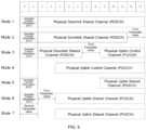
- FIG. 9 is a flowchart of the wireless resource scheduling method provided by another example of the present disclosure.
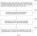
- the wireless resource scheduling method comprises: At block S901: determining, by a network side equipment, a second parameter value, wherein the second parameter value indicates a minimum time length of downlink transmission within one time unit, and the downlink transmission starts at the starting position of the time unit.
- the network side equipment determining the second parameter value may refer to the network side equipment receiving the second parameter value input by the network administrator, or the network side equipment determining the second parameter value based on the number of symbols required to be occupied for transmitting the downlink control information (DCI) and the number of symbols required to be occupied for transmitting the downlink measurement reference signals, wherein the number of symbols may refer to the number of orthogonal frequency division multiplexing (OFDM) symbols.
- DCI downlink control information
- OFDM orthogonal frequency division multiplexing
- the UE determines, based on the second parameter value indicated by the network side equipment, the minimum time length of downlink transmission in one sub-frame, one time slot or other time units, and during the dynamic scheduling stage, the length of transmission time occupied by the downlink signal may be greater than or equal to the above second parameter value.
- the network side equipment may also indicate the above second parameter value to the UE based on different message forms, for example, in the examples of the present disclosure, the second parameter value may also be indicated to the UE by one or more types of message forms: a system message, a UE-specific higher-layer signaling, cell-specific physical layer control information, UE-group-specific physical layer control information, and UE-specific physical layer control information.
- the value set of second parameters may be determined before the second parameter value is determined.
- the network side equipment determining the value set of second parameters may refer to the network side equipment receiving the value set of second parameters input by the network administrator, that is, the value set of second parameters may be defined empirically.
- the network side equipment may also determine the value set of second parameters based on the number of symbols that the UE needs to occupy for transmitting the DCI and/or the number of symbols that the UE needs to occupy for transmitting the downlink measurement reference signals.
- the network side equipment may select one second parameter value for one UE, or concurrently select one second parameter value for a group of UEs or all the UEs within a cell.
- one value may be selected as the second parameter value from the value set of second parameters based on the maximum of the numbers of symbols that the UEs in the group or all the UEs in the cell need to occupy for transmitting the DCI and/or the maximum of the numbers of symbols that the UEs in the group or all the UEs in the cell need to occupy for transmitting downlink measurement reference signals.
- the value set may be sent to the UE.
- the value set of second parameters may be sent by one or more of a system message, a UE-specific higher-layer signaling, cell-specific physical layer control information, UE-group-specific physical layer control information, and UE-specific physical layer control information.
- the network side equipment may select one value from the value set of second parameters as the second parameter value indicated to the UE, and send to the UE a second bit identifier indicating the second parameter value.
- the UE After receiving the second bit identifier, the UE searches the received value set of second parameters for the second parameter value corresponding to the second bit identifier from based on a predefined mapping rule.
- the predefined mapping rule may be, for example, that the bit identifiers are sequentially arranged in ascending order of 00, 01, 10, 11 and correspond to the parameter values arranged in ascending order in the value set of second parameters, respectively.
- the network side equipment may also send to the UE the mapping relation between the value set of second parameters and the bit identifiers.
- the above first parameter value and/or the second parameter value may also be determined by the network side equipment and then dynamically notified to the UE, or a semi-static manner may be used to predefine a value set, select a value from the value set for the UE, and dynamically indicate the same to the UE.
- the network side equipment may indicate the first parameter value and the second parameter value together to the UE, or indicate them separately. In the example below, the network side equipment may simultaneously indicate the first parameter value and the second parameter value to the UE.
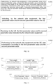
- FIG. 10 is a flowchart of the wireless resource scheduling method provided by another example of the present disclosure.
- the wireless resource scheduling method comprises:
- the network side equipment may indicate the first parameter value and the second parameter value to the UE after determining the first parameter value and the second parameter value, and then the network side equipment and the UE may perform data transmission with each other based on the indicated first parameter value and second parameter value.
- the present disclosure also provides examples of a wireless resource scheduling device corresponding to the wireless resource scheduling method, and examples of network side equipment and a UE. Since the problem-solving principle of the network side equipment and the UE in the examples of the present disclosure is similar to that of the wireless resource scheduling method in the examples of the present disclosure, as to the network side equipment and the UE, reference may be made to the examples of the method.
- FIG. 11 illustrates a wireless resource scheduling device provided by an example of the present disclosure, comprising:
- the above data transmission module 112 performing data transmission with the UE within the target time unit comprises:
- the wireless resource scheduling device further comprises:
- the dashed lines in the drawings illustrate that the time length determining module 113 may be connected with the length type determining module 111, representing that the time length determining module 113 may determine the transmission time length by acquiring the transmission length type from the length type determining module 111; moreover, the time length determining module 113 may be considered as a part of the data transmission module 112, or it may be construed that the data transmission module 112 may specifically realize calculation of the transmission time length by calling the time length determining module 113.
- the wireless resource scheduling device further comprises: a transmission type determining module 114 configured to determine a transmission type of the next time unit following the target time unit based on the time division duplexing (TDD) frame structure for data transmission between the network side equipment and the UE, with the transmission type being uplink or downlink.
- a transmission type determining module 114 configured to determine a transmission type of the next time unit following the target time unit based on the time division duplexing (TDD) frame structure for data transmission between the network side equipment and the UE, with the transmission type being uplink or downlink.
- TDD time division duplexing
- the above wireless resource scheduling device further comprises:
- the above data transmission module 112 notifying the UE of the transmission length type of the first channel within the target time unit comprises:
- the above wireless resource scheduling device further comprises:
- the first parameter value determining module 151 determines the first parameter value based on one or more the following information:
- the first parameter value indicating module 152 indicates the first parameter value to the UE in one of the following message forms: a system message, a UE-specific higher-layer signaling, cell-specific physical layer control information, UE-group-specific physical layer control information, and UE-specific physical layer control information.
- the first parameter value indicating module 152 selects, from a value set of the first parameter, one value as the first parameter value indicated to the UE based on one or more of types of the following information:
- the above device also comprises:
- the above wireless resource scheduling device also comprises: a first value set sending module 156 configured to send the value set of the first parameter to the UE in one of the following message forms: a system message, a UE-specific higher-layer signaling, cell-specific physical layer control information, UE-group-specific physical layer control information, and UE-specific physical layer control information.
- a first value set sending module 156 configured to send the value set of the first parameter to the UE in one of the following message forms: a system message, a UE-specific higher-layer signaling, cell-specific physical layer control information, UE-group-specific physical layer control information, and UE-specific physical layer control information.
- the second parameter value determining module 153 determines the second parameter value based on the following step: determining the second parameter value based on the number of symbols required to be occupied for transmitting the downlink control information (DCI) and/or the number of symbols required to be occupied for transmitting the downlink measurement reference signals.
- DCI downlink control information
- the second parameter value indicating module 154 is configured to send the second parameter value to the UE in one of the following message forms: a system message, a UE-specific higher-layer signaling, cell-specific physical layer control information, UE-group-specific physical layer control information, and UE-specific physical layer control information.
- the second parameter value determining module 153 determines the second parameter value based on the following step: selecting, based on the number of symbols required to be occupied for transmitting the downlink control information (DCI) and/or the number of symbols required to be occupied for transmitting the downlink measurement reference signals, one value from the value set of second parameters as the second parameter value indicated to the UE.
- DCI downlink control information
- the second parameter value indicating module 154 is configured to: send to the UE a second bit identifier indicating the second parameter value selected from the value set of second parameters.
- the above wireless resource scheduling device also comprises: a second value set sending module 157 configured to send the value set of second parameters to the UE in one of the following message forms: a system message, a UE-specific higher-layer signaling, cell-specific physical layer control information, UE-group-specific physical layer control information, and UE-specific physical layer control information.
- a second value set sending module 157 configured to send the value set of second parameters to the UE in one of the following message forms: a system message, a UE-specific higher-layer signaling, cell-specific physical layer control information, UE-group-specific physical layer control information, and UE-specific physical layer control information.
- FIG. 16 is a schematic diagram of the wireless resource scheduling device provided by another example of the present disclosure, comprising:
- the above wireless resource scheduling device also comprises:
- the above wireless resource scheduling device also comprises: a processing time reporting module 164 configured to report processing time of the UE so that the network side equipment determines the first parameter value for the UE based on the processing time of the UE, wherein the processing time of the UE includes at least one of the followings: time required by the UE for receiving and decoding a downlink channel, time required by the UE for generating an uplink transmission signal, and time required by the UE for switching from downlink reception to uplink transmission.
- a processing time reporting module 164 configured to report processing time of the UE so that the network side equipment determines the first parameter value for the UE based on the processing time of the UE, wherein the processing time of the UE includes at least one of the followings: time required by the UE for receiving and decoding a downlink channel, time required by the UE for generating an uplink transmission signal, and time required by the UE for switching from downlink reception to uplink transmission.
- the first parameter value receiving module 161 is configured to receive the first parameter value in one of the following message forms: a system message, a UE-specific higher-layer signaling, cell-specific physical layer control information, UE-group-specific physical layer control information, and UE-specific physical layer control information.
- the first parameter value receiving module 161 is configured to: receive a first bit identifier indicating the first parameter value, with the first bit identifier sent by the network side equipment, and determine the first parameter value indicated by the network side equipment from a value set of the first parameter based on the first bit identifier.
- the above wireless resource scheduling device also comprises: a first value set receiving module 165 configured to receive the value set of the first parameter in one of the following message forms: a system message, a UE-specific higher-layer signaling, cell-specific physical layer control information, UE-group-specific physical layer control information, and UE-specific physical layer control information.
- a first value set receiving module 165 configured to receive the value set of the first parameter in one of the following message forms: a system message, a UE-specific higher-layer signaling, cell-specific physical layer control information, UE-group-specific physical layer control information, and UE-specific physical layer control information.
- the second parameter value receiving module 163 is configured to: receive a second bit identifier indicating the second parameter value sent by the network side equipment, and determine from a value set of second parameters, based on the second bit identifier, the second parameter value indicated by the network side equipment.
- the above wireless resource scheduling device also comprises:
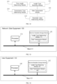
- an example of the present disclosure also provides network side equipment 170, the network side equipment 170 comprises a processor 171, a machine-readable storage medium 172 and a bus 173, wherein machine-readable instructions executable by the processor 171 are stored in the machine-readable storage medium 172, the processor 171 communicates with the machine-readable storage medium 172 via the bus 173, and when the machine-readable instructions are executed by the processor 171, the following processing is executed:
- the following processing is further executed: determining a second parameter value, wherein the second parameter value indicates the minimum time length of downlink transmission within the time unit, with the downlink transmission starting at the starting position of the time unit; and indicating the second parameter value to the UE.
- the following processing is executed: determining the first parameter value based on one or more the following information: a cell coverage distance; and processing time of the UE, including at least one of the following: time required for receiving and decoding a downlink channel, time required for generating an uplink transmission signal, and time required for switching from downlink reception to uplink transmission.
- the following processing is executed: indicating the first parameter value to the UE in one of the following message forms: a system message, a UE-specific higher-layer signaling, cell-specific physical layer control information, UE-group-specific physical layer control information, and UE-specific physical layer control information.
- the following processing is executed: selecting, from a value set of the first parameter, one value as the first parameter value indicated to the UE.
- the following processing is executed: selecting one value from a value set of the first parameter as the first parameter value indicated to the UE based on one or more the following information:
- the following processing is further executed: receiving the processing time reported by the UE.
- the following processing is further executed: sending to the UE a first bit identifier indicating the first parameter value selected from the value set of the first parameter.
- the following processing is executed: selecting one value from the value set of second parameters as the second parameter value indicated to the UE based on the number of symbols required to be occupied for transmitting the downlink control information (DCI) and/or the number of symbols required to be occupied for transmitting the downlink measurement reference signals.
- DCI downlink control information
- the following processing is executed: sending the value set of second parameters to the UE in one of the following message forms: a system message, a UE-specific higher-layer signaling, cell-specific physical layer control information, UE-group-specific physical layer control information, and UE-specific physical layer control information.
- the following processing is executed: receiving the value set of the first parameter in one of the following message forms: a system message, a UE-specific higher-layer signaling, cell-specific physical layer control information, UE-group-specific physical layer control information, and UE-specific physical layer control information.
- the following processing is executed: receiving a second bit identifier indicating the second parameter value sent by the network side equipment, and determining the second parameter value indicated by the network side equipment from the value set of second parameters based on the second bit identifier.
- the following processing is further executed: receiving the value set of second parameters in one of the following message forms: a system message, a UE-specific higher-layer signaling, cell-specific physical layer control information, UE-group-specific physical layer control information, and UE-specific physical layer control information.
- An example of the present disclosure also provides a computer-readable storage medium on which a computer program is stored a computer program, when the computer program is executed by the processor 181, the above functions of the user equipment 180 as shown in FIG. 18 are executed.
- the storage medium may be a general-purpose storage medium such as a removable disk, a hard disk, or the like, and when the computer program on the storage medium is executed, the above-described wireless resource scheduling method may be executed, so as to solve the problem that the current wireless resource scheduling method is poor in flexibility, and further achieve the effect of flexible resource scheduling.
- the functions can be stored on a computer readable storage medium.
- the substance of the technical solutions of the present disclosure, the part of the technical solutions of the present disclosure that makes contributions to the prior art, or part of the technical solutions can be embodied in the form of a software product, and the computer software product is stored on a storage medium and comprises some instructions for enabling one computer device (which can be a personal computer, a server, a network device or the like) to execute all or some of the steps of the methods in the examples of the present disclosure.
- the storage medium includes various mediums capable of storing program codes, such as a USB flash disk, a mobile hard disk, a read-only memory (ROM), a random access memory (RAM), a magnetic disk, or an optical disk.
Landscapes
- Engineering & Computer Science (AREA)
- Signal Processing (AREA)
- Computer Networks & Wireless Communication (AREA)
- Mobile Radio Communication Systems (AREA)
Claims (12)
- Verfahren zur drahtlosen Ressourcenplanung, wobei das Verfahren umfasst:Bestimmen (S301) eines Übertragungslängentyps eines ersten Kanals innerhalb einer Zielzeiteinheit für ein Benutzerendgerät UE (140) durch ein netzwerkseitiges Gerät (130); undBenachrichtigen (S302) des UE (140) durch das netzwerkseitige Gerät (130) über den Übertragungslängentyp des ersten Kanals innerhalb der Zielzeiteinheit und Durchführen einer Datenübertragung mit dem UE (140) innerhalb der Zielzeiteinheit basierend auf dem Übertragungslängentyp des ersten Kanals,wobei das netzwerkseitige Gerät (130), das eine Datenübertragung mit dem UE (140) innerhalb der Zielzeiteinheit basierend auf dem Übertragungslängentyp des ersten Kanals durchführt, umfasst:Bestimmen (S402), durch das netzwerkseitige Gerät (130), einer Übertragungszeitdauer innerhalb der Zielzeiteinheit eines oder mehrerer Kanaltypen, einschließlich des ersten Kanals, basierend auf dem Übertragungslängentyp des ersten Kanals, einem oder beiden eines ersten Parameterwerts und eines zweiten Parameterwerts und einem Kanaltyp des ersten Kanals; wobei der erste Parameterwert eine minimale Zeitdauer eines Intervalls zwischen einem Downlink-Signal und einem unmittelbar nachfolgenden Uplink-Signal angibt und der zweite Parameterwert eine minimale Zeitdauer der Downlink-Übertragung innerhalb der Zielzeiteinheit angibt, wobei die Downlink-Übertragung an der Startposition der Zielzeiteinheit beginnt; undDurchführen (S403) einer Datenübertragung mit dem UE (140) durch das netzwerkseitige Gerät (130) basierend auf der Übertragungszeitdauer des einen oder der mehreren Kanaltypen.
- Verfahren zur drahtlosen Ressourcenplanung nach Anspruch 1, wobei das Bestimmen (S402), durch das netzwerkseitige Gerät (130), einer Übertragungszeitdauer innerhalb der Zielzeiteinheit eines oder mehrerer Kanaltypen, einschließlich des ersten Kanals, basierend auf dem Übertragungslängentyp des ersten Kanals, einem oder beiden eines ersten Parameterwerts und eines zweiten Parameterwerts und einem Kanaltyp des ersten Kanals, umfasst:Bestimmen, ob der erste Kanal ein Physical Downlink Shared Channel PDSCH ist, die nächste Zeiteinheit nach der Zielzeiteinheit für den Downlink ist und der Übertragungslängentyp des PDSCH vom langen Typ ist, dass innerhalb der Zielzeiteinheit die Übertragungszeitdauer des PDSCH = die Länge der Zielzeiteinheit - der zweite Parameterwert - α1, worin α1 eine Konstante größer oder gleich 0 ist; wobei die Übertragungszeitdauer des PDSCH des langen Typs größer als die Länge der Zielzeiteinheit/2 ist;Bestimmen, ob der erste Kanal der PDSCH ist, die nächste Zeiteinheit nach der Zielzeiteinheit für den Uplink ist und der Übertragungslängentyp des PDSCH vom langen Typ ist, dass innerhalb der Zielzeiteinheit die Übertragungszeitdauer des PDSCH = die Länge der Zielzeiteinheit - der erste Parameterwert - der zweite Parameterwert - α1;Bestimmen, wenn der erste Kanal der PDSCH ist und der Übertragungslängentyp des PDSCH vom kurzen Typ ist, dass innerhalb der Zielzeiteinheit die Übertragungszeitdauer des PDSCH vom kurzen Typ = |die Länge der Zielzeiteinheit/β| - der zweite Parameterwert - α2, und dass innerhalb der Zielzeiteinheit die Übertragungszeitdauer eines Physical Uplink Control Channel PUCCH des kurzen Typs = |die Länge der Zielzeiteinheit/β| - der erste Parameterwert - α2; wobei β eine Konstante größer oder gleich 2 ist und α2 eine Konstante größer oder gleich 0 ist;Bestimmen, wenn der erste Kanal der PUCCH ist und der Übertragungslängentyp des PUCCH der lange Typ ist, dass innerhalb der Zielzeiteinheit die Übertragungszeitdauer des PUCCH = die Länge der Zielzeiteinheit - der erste Parameterwert - der zweite Parameterwert - α1, wobei die Übertragungszeitdauer des PUCCH des langen Typs größer als die Länge der Zielzeiteinheit/2 ist;Bestimmen, wenn der erste Kanal ein Physical Uplink Shared Channel PUSCH ist und der Übertragungslängentyp des PUSCH der kurze Typ ist, dass innerhalb der Zielzeiteinheit die Übertragungszeitdauer des PUSCH = |die Länge der Zielzeiteinheit/β| - der erste Parameterwert - α2; undBestimmen, wenn der erste Kanal der PUSCH ist und der Übertragungslängentyp des PUSCH der lange Typ ist, dass innerhalb der Zielzeiteinheit die Übertragungszeitdauer des PUSCH = die Länge der Zielzeiteinheit - der erste Parameterwert - der zweite Parameterwert - α1, worin α1 eine Konstante größer oder gleich 0 ist; wobei die Übertragungszeitdauer des PUSCH des langen Typs größer als die Länge der Zielzeiteinheit/2 ist.
- Verfahren zur drahtlosen Ressourcenplanung nach Anspruch 1 oder 2, ferner umfassend:Auswählen, durch das netzwerkseitige Gerät (130), eines Werts aus einem Wertesatz erster Parameter als ersten Parameterwert und Senden einer ersten Bitkennung, die den ausgewählten ersten Parameterwert angibt, an das UE (140); und/oderAuswählen, durch das netzwerkseitige Gerät (130), eines Werts aus einem Wertesatz zweiter Parameter als zweiten Parameterwert basierend auf der Anzahl der Symbole, die zum Übertragen von Downlink-Steuerinformationen DCI belegt werden müssen, und/oder der Anzahl der Symbole, die zum Übertragen von Downlink-Messreferenzsignalen belegt werden müssen, und Senden einer zweiten Bitkennung an das UE (140), die den ausgewählten zweiten Parameterwert angibt.
- Verfahren zur drahtlosen Ressourcenplanung nach einem der Ansprüche 1 bis 3, wobei die Benachrichtigung des UE (140) durch das netzwerkseitige Gerät (130) über den Übertragungslängentyp des ersten Kanals innerhalb der Zielzeiteinheit umfasst:
Senden einer dritten Bitkennung durch das netzwerkseitige Gerät (130) an das UE (140) mittels Downlink-Steuerinformationen DCI, wobei die dritte Bitkennung den Übertragungslängentyp des ersten Kanals angibt - Netzwerkseitiges Gerät, wobei das netzwerkseitige Gerät umfasst:
einen Prozessor (171), ein nichtflüchtiges Speichermedium und einen Bus (173), eine vom Prozessor (171) ausführbare maschinenlesbare Anweisung ist im nichtflüchtigen Speichermedium gespeichert, der Prozessor (171) kommuniziert über den Bus (173) mit dem nichtflüchtigen Speichermedium, und wenn die maschinenlesbare Anweisung vom Prozessor (171) ausgeführt wird, wird die folgende Verarbeitung ausgeführt:Bestimmen (S301) eines Übertragungslängentyps eines ersten Kanals innerhalb einer Zielzeiteinheit für ein UE (140); undBenachrichtigen (S302) des UE (140) über den Übertragungslängentyp des ersten Kanals innerhalb der Zielzeiteinheit und Durchführen einer Datenübertragung mit der UE-Einheit (140) basierend auf dem Übertragungslängentyp des ersten Kanals innerhalb der Zielzeiteinheit,wobei hinsichtlich der Durchführung einer Datenübertragung mit dem UE (140) basierend auf dem Übertragungslängentyp des ersten Kanals, wenn die maschinenlesbare Anweisung durch den Prozessor (171) ausgeführt wird, die folgende Verarbeitung ausgeführt wird:Bestimmen (S402) einer Übertragungszeitdauer innerhalb der Zielzeiteinheit eines oder mehrerer Kanaltypen, einschließlich des ersten Kanals, basierend auf dem Übertragungslängentyp des ersten Kanals oder beiden eines ersten Parameterwerts und eines zweiten Parameterwerts und einem Kanaltyp des ersten Kanals; wobei der erste Parameterwert eine minimale Zeitdauer eines Intervalls zwischen einem Downlink-Signal und einem unmittelbar nachfolgenden Uplink-Signal angibt; und der zweite Parameterwert eine Mindestzeitdauer der Downlink-Übertragung innerhalb der Zielzeiteinheit angibt, wobei die Downlink-Übertragung an einer Startposition der Zielzeiteinheit beginnt; undDurchführen (S403) einer Datenübertragung mit dem UE (140) basierend auf der Übertragungszeitdauer des einen oder der mehreren Kanaltypen. - Netzwerkseitiges Gerät nach Anspruch 5, wobei zum Bestimmen einer Übertragungszeitdauer innerhalb der Zielzeiteinheit eines oder mehrerer Kanaltypen, einschließlich des ersten Kanals, basierend auf dem Übertragungslängentyp des ersten Kanals, einem oder beiden eines ersten Parameterwerts und eines zweiten Parameterwerts und einem Kanaltyp des ersten Kanals, wenn die maschinenlesbare Anweisung durch den Prozessor (171) ausgeführt wird, die folgende Verarbeitung ausgeführt wird:Bestimmen, ob der erste Kanal ein Physical Downlink Shared Channel PDSCH ist, die nächste Zeiteinheit nach der Zielzeiteinheit für den Downlink ist und der Übertragungslängentyp des PDSCH vom langen Typ ist, dass innerhalb der Zielzeiteinheit die Übertragungszeitdauer des PDSCH = die Länge der Zielzeiteinheit - der zweite Parameterwert - α1, worin α1 eine Konstante größer oder gleich 0 ist; wobei die Übertragungszeitdauer des PDSCH des langen Typs größer als die Länge der Zielzeiteinheit/2 ist;Bestimmen, ob der erste Kanal der PDSCH ist, die nächste Zeiteinheit nach der Zielzeiteinheit für den Uplink ist und der Übertragungslängentyp des PDSCH vom langen Typ ist, dass innerhalb der Zielzeiteinheit die Übertragungszeitdauer des PDSCH = die Länge der Zielzeiteinheit - der erste Parameterwert - der zweite Parameterwert - α1;Bestimmen, wenn der erste Kanal der PDSCH ist und der Übertragungslängentyp des PDSCH vom kurzen Typ ist, dass innerhalb der Zielzeiteinheit die Übertragungszeitdauer des PDSCH vom kurzen Typ = |die Länge der Zielzeiteinheit/β| - der zweite Parameterwert - α2, und dass innerhalb der Zielzeiteinheit die Übertragungszeitdauer eines Physical Uplink Control Channel PUCCH des kurzen Typs = |die Länge der Zielzeiteinheit/β| - der erste Parameterwert - α2; wobei β eine Konstante größer oder gleich 2 ist und α2 eine Konstante größer oder gleich 0 ist;Bestimmen, wenn der erste Kanal der PUCCH ist und der Übertragungslängentyp des PUCCH der lange Typ ist, dass innerhalb der Zielzeiteinheit die Übertragungszeitdauer des PUCCH = die Länge der Zielzeiteinheit - der erste Parameterwert - der zweite Parameterwert - α1, wobei die Übertragungszeitdauer des PUCCH des langen Typs größer als die Länge der Zielzeiteinheit/2 ist;Bestimmen, wenn der erste Kanal ein Physical Uplink Shared Channel PUSCH ist und der Übertragungslängentyp des PUSCH der kurze Typ ist, dass innerhalb der Zielzeiteinheit die Übertragungszeitdauer des PUSCH = |die Länge der Zielzeiteinheit/β| - der erste Parameterwert - α2; undBestimmen, wenn der erste Kanal der PUSCH ist und der Übertragungslängentyp des PUSCH der lange Typ ist, dass innerhalb der Zielzeiteinheit die Übertragungszeitdauer des PUSCH = die Länge der Zielzeiteinheit - der erste Parameterwert - der zweite Parameterwert - α1, worin α1 eine Konstante größer oder gleich 0 ist; wobei die Übertragungszeitdauer des PUSCH des langen Typs größer als die Länge der Zielzeiteinheit/2 ist.
- Netzwerkseitiges Gerät nach Anspruch 5 oder 6, wobei, wenn die maschinenlesbare Anweisung durch den Prozessor (171) ausgeführt wird, folgende Verarbeitung ferner ausgeführt wird:Auswählen eines Wertes aus einem Wertesatz erster Parameter als den ersten Parameterwert und Senden einer ersten Bitkennung, die den ausgewählten ersten Parameterwert angibt, an das UE (140); und/oderAuswählen eines Wertes aus einem Wertesatz zweiter Parameter als zweiten Parameterwert basierend auf der Anzahl der Symbole, die zum Senden von Downlink-Steuerinformationen DCI belegt werden müssen, und/oder der Anzahl der Symbole, die zum Senden von Downlink-Messreferenzsignalen belegt werden müssen, und Senden einer zweiten Bitkennung an das UE (140), die den ausgewählten zweiten Parameterwert angibt.
- Netzwerkseitiges Gerät nach einem der Ansprüche 5 bis 7, wobei hinsichtlich der Benachrichtigung des UE (140) über den Übertragungslängentyp des ersten Kanals innerhalb der Zielzeiteinheit, wenn die maschinenlesbare Anweisung durch den Prozessor (171) ausgeführt wird, die folgende Verarbeitung ausgeführt wird: Senden einer dritten Bitkennung an das UE (140) mittels der Downlink-Steuerinformationen DCI, wobei die dritte Bitkennung den Übertragungslängentyp des ersten Kanals angibt.
- UE, wobei das UE einen Prozessor (181), ein nichtflüchtiges Speichermedium und einen Bus (183) umfasst, eine vom Prozessor (181) ausführbare maschinenlesbare Anweisung ist im nichtflüchtigen Speichermedium gespeichert, der Prozessor (181) kommuniziert über den Bus (183) mit dem nichtflüchtigen Speichermedium, und wenn die maschinenlesbare Anweisung vom Prozessor (181) ausgeführt wird, wird die folgende Verarbeitung ausgeführt:Empfangen eines Übertragungslängentyps eines ersten Kanals innerhalb einer Zielzeiteinheit, wobei der Übertragungslängentyp von einem netzwerkseitigen Gerät (130) mitgeteilt wird; undDurchführen einer Datenübertragung mit dem netzwerkseitigen Gerät (130) innerhalb der Zielzeiteinheit basierend auf dem Übertragungslängentyp des ersten Kanals,wobei hinsichtlich der Durchführung der Datenübertragung mit dem netzwerkseitigen Gerät (130) innerhalb der Zielzeiteinheit basierend auf dem Übertragungslängentyp des ersten Kanals, wenn die maschinenlesbare Anweisung durch den Prozessor (181) ausgeführt wird, die folgende Verarbeitung ausgeführt wird:Bestimmen einer Übertragungszeitdauer innerhalb der Zielzeiteinheit eines oder mehrerer Kanaltypen, einschließlich des ersten Kanals, basierend auf dem Übertragungslängentyp des ersten Kanals oder beiden eines ersten Parameterwerts und eines zweiten Parameterwerts und einem Kanaltyp des ersten Kanals; wobei der erste Parameterwert eine minimale Zeitdauer eines Intervalls zwischen einem Downlink-Signal und einem unmittelbar nachfolgenden Uplink-Signal angibt; und der zweite Parameterwert eine Mindestzeitdauer der Downlink-Übertragung innerhalb der Zielzeiteinheit angibt, wobei die Downlink-Übertragung an einer Startposition der Zielzeiteinheit beginnt; undDurchführen einer Datenübertragung mit dem netzwerkseitigen Gerät (130) basierend auf der Übertragungszeitdauer des einen oder der mehreren Kanaltypen.
- UE nach Anspruch 9, wobei zum Bestimmen einer Übertragungszeitdauer innerhalb der Zielzeiteinheit eines oder mehrerer Kanaltypen, einschließlich des ersten Kanals, basierend auf dem Übertragungslängentyp des ersten Kanals, einem oder beiden eines ersten Parameterwerts und eines zweiten Parameterwerts und einem Kanaltyp des ersten Kanals, wenn die maschinenlesbare Anweisung durch den Prozessor (181) ausgeführt wird, die folgende Verarbeitung ausgeführt wird:Bestimmen, ob der erste Kanal ein Physical Downlink Shared Channel PDSCH ist, die nächste Zeiteinheit nach der Zielzeiteinheit für den Downlink ist und der Übertragungslängentyp des PDSCH vom langen Typ ist, dass innerhalb der Zielzeiteinheit die Übertragungszeitdauer des PDSCH = die Länge der Zielzeiteinheit - der zweite Parameterwert - α1, worin α1 eine Konstante größer oder gleich 0 ist; wobei die Übertragungszeitdauer des PDSCH des langen Typs größer als die Länge der Zielzeiteinheit/2 ist;Bestimmen, ob der erste Kanal der PDSCH ist, die nächste Zeiteinheit nach der Zielzeiteinheit für den Uplink ist und der Übertragungslängentyp des PDSCH vom langen Typ ist, dass innerhalb der Zielzeiteinheit die Übertragungszeitdauer des PDSCH = die Länge der Zielzeiteinheit - der erste Parameterwert - der zweite Parameterwert - α1;Bestimmen, wenn der erste Kanal der PDSCH ist und der Übertragungslängentyp des PDSCH vom kurzen Typ ist, dass innerhalb der Zielzeiteinheit die Übertragungszeitdauer des PDSCH vom kurzen Typ = |die Länge der Zielzeiteinheit/β| - der zweite Parameterwert - α2, und dass innerhalb der Zielzeiteinheit die Übertragungszeitdauer eines Physical Uplink Control Channel PUCCH des kurzen Typs = |die Länge der Zielzeiteinheit/β| - der erste Parameterwert - α2; wobei β eine Konstante größer oder gleich 2 ist und α2 eine Konstante größer oder gleich 0 ist;Bestimmen, wenn der erste Kanal der PUCCH ist und der Übertragungslängentyp des PUCCH der lange Typ ist, dass innerhalb der Zielzeiteinheit die Übertragungszeitdauer des PUCCH = die Länge der Zielzeiteinheit - der erste Parameterwert - der zweite Parameterwert - α1, wobei die Übertragungszeitdauer des PUCCH des langen Typs größer als die Länge der Zielzeiteinheit/2 ist;Bestimmen, wenn der erste Kanal ein Physical Uplink Shared Channel PUSCH ist und der Übertragungslängentyp des PUSCH der kurze Typ ist, dass innerhalb der Zielzeiteinheit die Übertragungszeitdauer des PUSCH = |die Länge der Zielzeiteinheit/β| - der erste Parameterwert - α2; undBestimmen, wenn der erste Kanal der PUSCH ist und der Übertragungslängentyp des PUSCH der lange Typ ist, dass innerhalb der Zielzeiteinheit die Übertragungszeitdauer des PUSCH = die Länge der Zielzeiteinheit - der erste Parameterwert - der zweite Parameterwert - α1, worin α1 eine Konstante größer oder gleich 0 ist; wobei die Übertragungszeitdauer des PUSCH des langen Typs größer als die Länge der Zielzeiteinheit/2 ist.
- UE nach Anspruch 9 oder 10, wobei, wenn die maschinenlesbare Anweisung durch den Prozessor (181) ausgeführt wird, folgende Verarbeitung ferner ausgeführt wird:
Empfangen einer ersten Bitkennung, die den ersten Parameterwert angibt und von dem netzwerkseitigen Gerät (130) gesendet wurde, und Bestimmen des ersten Parameterwerts, der von dem netzwerkseitigen Gerät (130) angegeben wird, aus einem Wertesatz erster Parameter basierend auf der ersten Bitkennung; und/oder Empfangen einer zweiten Bitkennung durch das UE, die den zweiten Parameterwert angibt und von dem netzwerkseitigen Gerät (130) gesendet wurde, und Bestimmen des zweiten Parameterwerts, der von dem netzwerkseitigen Gerät (130) angegeben wird, aus einem Wertesatz zweiter Parameter basierend auf der zweiten Bitkennung. - UE nach einem der Ansprüche 9 bis 11, wobei hinsichtlich des Empfangs eines Übertragungslängentyps eines ersten Kanals innerhalb einer Zielzeiteinheit mit dem Übertragungslängentyp, der von einem netzwerkseitigen Gerät (130) mitgeteilt wird, wenn die maschinenlesbare Anweisung durch den Prozessor (181) ausgeführt wird, die folgende Verarbeitung ausgeführt wird:
Empfangen einer dritten Bitkennung, die den Übertragungslängentyp des ersten Kanals angibt, wobei die dritte Bitkennung von dem netzwerkseitigen Gerät (130) mittels Downlink-Steuerinformationen DCI gesendet wird.
Applications Claiming Priority (2)
| Application Number | Priority Date | Filing Date | Title |
|---|---|---|---|
| CN201810273913.9A CN109688627B (zh) | 2018-03-29 | 2018-03-29 | 一种无线资源调度方法、网络侧设备及用户设备 |
| PCT/CN2019/080615 WO2019185055A1 (zh) | 2018-03-29 | 2019-03-29 | 无线资源调度 |
Publications (3)
| Publication Number | Publication Date |
|---|---|
| EP3780840A1 EP3780840A1 (de) | 2021-02-17 |
| EP3780840A4 EP3780840A4 (de) | 2021-05-19 |
| EP3780840B1 true EP3780840B1 (de) | 2025-07-09 |
Family
ID=66184420
Family Applications (1)
| Application Number | Title | Priority Date | Filing Date |
|---|---|---|---|
| EP19778053.9A Active EP3780840B1 (de) | 2018-03-29 | 2019-03-29 | Drahtlose betriebsmittelplanung |
Country Status (5)
| Country | Link |
|---|---|
| US (2) | US11716731B2 (de) |
| EP (1) | EP3780840B1 (de) |
| JP (1) | JP7053875B2 (de) |
| CN (1) | CN109688627B (de) |
| WO (1) | WO2019185055A1 (de) |
Families Citing this family (4)
| Publication number | Priority date | Publication date | Assignee | Title |
|---|---|---|---|---|
| CN109688627B (zh) * | 2018-03-29 | 2022-05-10 | 新华三技术有限公司 | 一种无线资源调度方法、网络侧设备及用户设备 |
| CN111278131B (zh) | 2019-08-12 | 2023-12-05 | 维沃移动通信有限公司 | 一种调度方法、网络设备及终端 |
| KR20210049612A (ko) * | 2019-10-25 | 2021-05-06 | 삼성전자주식회사 | 무선 통신 시스템에서 데이터를 송수신하는 방법 및 장치 |
| WO2022011503A1 (en) * | 2020-07-13 | 2022-01-20 | Qualcomm Incorporated | Frame structures for uplink carrier aggregation of two time division duplex carriers |
Family Cites Families (17)
| Publication number | Priority date | Publication date | Assignee | Title |
|---|---|---|---|---|
| US6240083B1 (en) | 1997-02-25 | 2001-05-29 | Telefonaktiebolaget L.M. Ericsson | Multiple access communication network with combined contention and reservation mode access |
| KR20010056132A (ko) | 1999-12-14 | 2001-07-04 | 서평원 | 압축 모드를 위한 데이터 전송 방법 |
| KR101559295B1 (ko) * | 2009-12-04 | 2015-10-12 | 삼성전자주식회사 | 공간 분할 다중 사용자 다중 입력 다중 출력 방식을 이용하는 통신 시스템 |
| CN102413576B (zh) * | 2011-12-21 | 2014-04-09 | 电信科学技术研究院 | 一种pdcch发送、接收方法及设备 |
| US9444891B2 (en) | 2013-07-01 | 2016-09-13 | Emoire Technology Development LLC | Data migration in a storage network |
| WO2015013862A1 (en) * | 2013-07-29 | 2015-02-05 | Qualcomm Incorporated | Dynamic indication of time division (tdd) duplex uplink/downlink subframe configurations |
| MX381821B (es) | 2014-11-15 | 2025-03-13 | Panasonic Ip Corp America | Método de programación de recursos, método de determinación de recursos, equipo de enodob y de usuario. |
| CN106550465B (zh) * | 2015-09-22 | 2022-04-19 | 中兴通讯股份有限公司 | 发送、接收短传输时间间隔通信的资源分配信息的方法和装置 |
| ES3013564T3 (en) * | 2015-12-07 | 2025-04-14 | Ericsson Telefon Ab L M | Uplink control channel configuration for unlicensed carriers |
| CN106954278B (zh) * | 2016-01-07 | 2021-09-28 | 中兴通讯股份有限公司 | 确定随机接入无线网络临时标识的方法、用户设备和基站 |
| BR112018015381A2 (pt) | 2016-02-03 | 2018-12-18 | Sony Corp | aparelho, método e sistema para comunicação sem fio, e, programa de computador |
| CN108352975B (zh) | 2016-02-04 | 2021-09-07 | 韩国电子通信研究院 | 支持授权和非授权频带的网络中的通信方法 |
| CN106231677B (zh) * | 2016-07-29 | 2020-01-10 | 宇龙计算机通信科技(深圳)有限公司 | 一种通信的方法及基站 |
| WO2018031623A1 (en) * | 2016-08-11 | 2018-02-15 | Intel Corporation | Flexible transmission time interval and on slot aggregation for data transmission for new radio |
| US10708938B2 (en) * | 2016-10-31 | 2020-07-07 | Samsung Electronics Co., Ltd. | Transmission of UL control channels with dynamic structures |
| CN116685000A (zh) * | 2017-06-16 | 2023-09-01 | 华为技术有限公司 | 一种无线通信方法和设备 |
| CN109688627B (zh) * | 2018-03-29 | 2022-05-10 | 新华三技术有限公司 | 一种无线资源调度方法、网络侧设备及用户设备 |
-
2018
- 2018-03-29 CN CN201810273913.9A patent/CN109688627B/zh active Active
-
2019
- 2019-03-29 EP EP19778053.9A patent/EP3780840B1/de active Active
- 2019-03-29 WO PCT/CN2019/080615 patent/WO2019185055A1/zh not_active Ceased
- 2019-03-29 US US17/042,733 patent/US11716731B2/en active Active
- 2019-03-29 JP JP2020552229A patent/JP7053875B2/ja active Active
-
2023
- 2023-06-14 US US18/209,969 patent/US12309787B2/en active Active
Also Published As
| Publication number | Publication date |
|---|---|
| US20210022164A1 (en) | 2021-01-21 |
| JP2021516925A (ja) | 2021-07-08 |
| JP7053875B2 (ja) | 2022-04-12 |
| US12309787B2 (en) | 2025-05-20 |
| WO2019185055A1 (zh) | 2019-10-03 |
| EP3780840A1 (de) | 2021-02-17 |
| CN109688627A (zh) | 2019-04-26 |
| US11716731B2 (en) | 2023-08-01 |
| CN109688627B (zh) | 2022-05-10 |
| US20230328737A1 (en) | 2023-10-12 |
| EP3780840A4 (de) | 2021-05-19 |
Similar Documents
| Publication | Publication Date | Title |
|---|---|---|
| KR102696445B1 (ko) | 면허 및 비면허 대역들을 지원하는 네트워크에서 통신 노드의 동작 방법 | |
| US11075719B2 (en) | Wireless communication method supporting HARQ, user equipment, and base station | |
| EP4213565B1 (de) | Nutzergerät, basisstation und entprechende verfahren | |
| CN114826499B (zh) | 识别用于发送第一上行链路信道的资源 | |
| US11425697B2 (en) | Dynamic management of uplink control signaling resources in wireless network | |
| US11985635B2 (en) | Wireless communication method, system, network device, and user equipment for improving transmission performance | |
| KR102138532B1 (ko) | 기기-대-기기 통신을 위한 스케줄링 방법 및 이를 위한 장치 | |
| US12185280B2 (en) | Resource management for wireless backhaul networks | |
| EP2536203A1 (de) | Verfahren, system und vorrichtung zur terminierung nicht konfligierender direktzugangs- und sendepräambeln | |
| US10517091B2 (en) | Data transmission method and device | |
| US20150016410A1 (en) | Device to device communication method and device for performing same | |
| EP3160201A1 (de) | Verfahren zur bestimmung einer ressource für kommunikation zwischen zwei vorrichtungen in einem drahtloskommunikationssystem und vorrichtung dafür | |
| US12309787B2 (en) | Wireless resource scheduling | |
| EP3499773B1 (de) | Verfahren und vorrichtung zur übertragung eines uplink-kanals | |
| US20180338306A1 (en) | Uplink information transmission method and apparatus | |
| WO2015009123A1 (ko) | 무선 통신 시스템에서 d2d(device-to-device) 통신을 위한 탐색 신호 검출방법 및 이를 위한 장치 | |
| US10980013B2 (en) | Data transmission method and device | |
| US10433322B2 (en) | Base station and wireless device used in wireless communication system | |
| WO2014116078A1 (ko) | 무선 통신 시스템에서 단말의 통신 방법 및 장치 | |
| CN110830172B (zh) | 非授权频段harq反馈的指示、发送方法及装置、存储介质、基站、终端 | |
| JPWO2016117645A1 (ja) | ユーザ端末、無線基地局及び無線通信方法 | |
| US20200214004A1 (en) | Data communication method, terminal device, and network device | |
| CN108271251A (zh) | 一种上行控制的资源确定方法、装置、发送端和接收端 | |
| US20170273091A1 (en) | Method and device for receiving signal in wireless access system supporting fdr transmission | |
| US11115993B2 (en) | Data transmission method, terminal device, and access network device |
Legal Events
| Date | Code | Title | Description |
|---|---|---|---|
| STAA | Information on the status of an ep patent application or granted ep patent |
Free format text: STATUS: THE INTERNATIONAL PUBLICATION HAS BEEN MADE |
|
| PUAI | Public reference made under article 153(3) epc to a published international application that has entered the european phase |
Free format text: ORIGINAL CODE: 0009012 |
|
| STAA | Information on the status of an ep patent application or granted ep patent |
Free format text: STATUS: REQUEST FOR EXAMINATION WAS MADE |
|
| 17P | Request for examination filed |
Effective date: 20201009 |
|
| AK | Designated contracting states |
Kind code of ref document: A1 Designated state(s): AL AT BE BG CH CY CZ DE DK EE ES FI FR GB GR HR HU IE IS IT LI LT LU LV MC MK MT NL NO PL PT RO RS SE SI SK SM TR |
|
| AX | Request for extension of the european patent |
Extension state: BA ME |
|
| A4 | Supplementary search report drawn up and despatched |
Effective date: 20210419 |
|
| RIC1 | Information provided on ipc code assigned before grant |
Ipc: H04W 72/12 20090101AFI20210413BHEP Ipc: H04L 5/00 20060101ALI20210413BHEP |
|
| DAV | Request for validation of the european patent (deleted) | ||
| DAX | Request for extension of the european patent (deleted) | ||
| STAA | Information on the status of an ep patent application or granted ep patent |
Free format text: STATUS: EXAMINATION IS IN PROGRESS |
|
| 17Q | First examination report despatched |
Effective date: 20230209 |
|
| REG | Reference to a national code |
Ref country code: DE Ref legal event code: R079 Free format text: PREVIOUS MAIN CLASS: H04W0072120000 Ipc: H04L0005000000 Ref country code: DE Ref legal event code: R079 Ref document number: 602019072325 Country of ref document: DE Free format text: PREVIOUS MAIN CLASS: H04W0072120000 Ipc: H04L0005000000 |
|
| GRAP | Despatch of communication of intention to grant a patent |
Free format text: ORIGINAL CODE: EPIDOSNIGR1 |
|
| STAA | Information on the status of an ep patent application or granted ep patent |
Free format text: STATUS: GRANT OF PATENT IS INTENDED |
|
| RIC1 | Information provided on ipc code assigned before grant |
Ipc: H04W 72/23 20230101ALI20250314BHEP Ipc: H04L 5/14 20060101ALI20250314BHEP Ipc: H04L 5/00 20060101AFI20250314BHEP |
|
| INTG | Intention to grant announced |
Effective date: 20250402 |
|
| GRAS | Grant fee paid |
Free format text: ORIGINAL CODE: EPIDOSNIGR3 |
|
| GRAA | (expected) grant |
Free format text: ORIGINAL CODE: 0009210 |
|
| STAA | Information on the status of an ep patent application or granted ep patent |
Free format text: STATUS: THE PATENT HAS BEEN GRANTED |
|
| AK | Designated contracting states |
Kind code of ref document: B1 Designated state(s): AL AT BE BG CH CY CZ DE DK EE ES FI FR GB GR HR HU IE IS IT LI LT LU LV MC MK MT NL NO PL PT RO RS SE SI SK SM TR |
|
| REG | Reference to a national code |
Ref country code: GB Ref legal event code: FG4D |
|
| REG | Reference to a national code |
Ref country code: CH Ref legal event code: EP |
|
| REG | Reference to a national code |
Ref country code: IE Ref legal event code: FG4D |
|
| REG | Reference to a national code |
Ref country code: DE Ref legal event code: R096 Ref document number: 602019072325 Country of ref document: DE |
|
| P01 | Opt-out of the competence of the unified patent court (upc) registered |
Free format text: CASE NUMBER: UPC_APP_7759_3780840/2025 Effective date: 20250924 |
|
| REG | Reference to a national code |
Ref country code: NL Ref legal event code: MP Effective date: 20250709 |