EP3780827B1 - Radio base station, user terminal, radio communication system and radio communication method - Google Patents
Radio base station, user terminal, radio communication system and radio communication method Download PDFInfo
- Publication number
- EP3780827B1 EP3780827B1 EP20198034.9A EP20198034A EP3780827B1 EP 3780827 B1 EP3780827 B1 EP 3780827B1 EP 20198034 A EP20198034 A EP 20198034A EP 3780827 B1 EP3780827 B1 EP 3780827B1
- Authority
- EP
- European Patent Office
- Prior art keywords
- frequency resource
- downlink control
- user terminal
- control information
- enhanced pdcch
- Prior art date
- Legal status (The legal status is an assumption and is not a legal conclusion. Google has not performed a legal analysis and makes no representation as to the accuracy of the status listed.)
- Active
Links
Images


Classifications
-
- H—ELECTRICITY
- H04—ELECTRIC COMMUNICATION TECHNIQUE
- H04L—TRANSMISSION OF DIGITAL INFORMATION, e.g. TELEGRAPHIC COMMUNICATION
- H04L5/00—Arrangements affording multiple use of the transmission path
- H04L5/003—Arrangements for allocating sub-channels of the transmission path
- H04L5/0053—Allocation of signalling, i.e. of overhead other than pilot signals
-
- H—ELECTRICITY
- H04—ELECTRIC COMMUNICATION TECHNIQUE
- H04W—WIRELESS COMMUNICATION NETWORKS
- H04W72/00—Local resource management
- H04W72/20—Control channels or signalling for resource management
- H04W72/23—Control channels or signalling for resource management in the downlink direction of a wireless link, i.e. towards a terminal
-
- H—ELECTRICITY
- H04—ELECTRIC COMMUNICATION TECHNIQUE
- H04L—TRANSMISSION OF DIGITAL INFORMATION, e.g. TELEGRAPHIC COMMUNICATION
- H04L5/00—Arrangements affording multiple use of the transmission path
- H04L5/003—Arrangements for allocating sub-channels of the transmission path
- H04L5/0037—Inter-user or inter-terminal allocation
-
- H—ELECTRICITY
- H04—ELECTRIC COMMUNICATION TECHNIQUE
- H04W—WIRELESS COMMUNICATION NETWORKS
- H04W72/00—Local resource management
- H04W72/04—Wireless resource allocation
- H04W72/044—Wireless resource allocation based on the type of the allocated resource
- H04W72/0453—Resources in frequency domain, e.g. a carrier in FDMA
Definitions
- the present invention relates to a radio base station, a user terminal, a radio communication system and a radio communication method in a next-generation radio communication system.
- LTE-Advanced or “LTE enhancement” (hereinafter referred to as "LTE-A")
- LTE-A LTE enhancement
- MIMO Multi-Input Multi-Output
- a plurality of transmitting/receiving antennas are provided in the transmitter/receiver, so that different transmission information sequences are transmitted from different transmitting antennas at the same time.
- a radio base station a user terminal, a radio communication method and a radio communication system that can adequately allocate radio resources to downlink control information in an expanded radio resource region for downlink control channels. Especially, it is possible to prevent the deterioration of the efficiency of use of radio resources when there is little downlink control information to be transmitted in predetermined time resource units such as subframes.
- MU-MIMO transmission it is possible to transmit data to a plurality of user terminal UEs in the same time and in the same frequency. Consequently, in the PDSCH region of FIG. 2 , it may be possible to multiplex data for user terminal UE #1 and data for user terminal UE #5 over the same frequency region. Similarly, it may also be possible to multiplex data for user terminal UE #4 and data for user terminal UE #6 over the same frequency region.
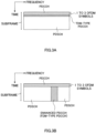
- a PDCCH that is frequency-division-multiplexed with the PDSCH in the FDM approach will be referred to as an “enhanced PDCCH.”
- This enhanced PDCCH may also be referred to as an “enhanced downlink control channel (enhanced physical downlink control channel),” "ePDCCH,” “E-PDCCH,” “FDM-type PDCCH,” “UE-PDCCH,” and so on.
- enhanced PDCCH resources are comprised of a predetermined number of resource block pairs (hereinafter referred to as "PRB (Physical Resource Block) pairs") that are distributed over the system band.
- PRB Physical Resource Block
- a PRB pair is formed with two PRBs that are consecutive along the time direction, and is identified by a PRB index that is assigned along the frequency direction.
- a plurality of PRB pairs to constitute enhanced PDCCH resources are determined by a higher layer. The PRB indices to identify each of these plurality of PRB pairs are reported to a user terminal UE through higher layer signaling.
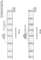
- FIG. 5B limiting the number of PRB pairs where the division units of one piece of DCI are mapped in a distributed manner is under study.
- the number of PRB pairs where the division units of one piece of DCI are mapped in a distributed manner is limited to four.
- eight division units of one piece of DCI are mapped in twos to four PRB pairs in a distributed manner.
- FIG. 5B compared with the case shown in FIG. 5A , it is possible to increase the number of PRB pairs where the PDSCH can be mapped.
- DCI for each user terminal UE is mapped to a plurality of PRB pairs forming the enhanced PDCCH set allocated to that user terminal UE in a distributed manner.
- DCI for user terminal UEs #1 to #5 is mapped to four PRB pairs which form enhanced PDCCH set #1 in a distributed manner.
- DCI for user terminal UEs #6 to #10 is mapped to four PRB pairs which form enhanced PDCCH set #2 in a distributed manner.
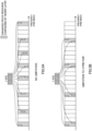
- enhanced PDCCH sets are selected so that the number of enhanced PDCCH sets to use to transmit DCI becomes minimum, and the DCI is mapped to the PRB pairs constituting the selected enhanced PDCCH sets.
- both enhanced PDCCH sets #1 and #2 are selected because one enhanced PDCCH set cannot provide sufficient resources.
- DCI for part of the user terminal UEs (for example, user terminal UEs #1 to #4) are mapped to the PRB pairs constituting enhanced PDCCH set #1, and DCI for the rest of the user terminal UEs (for example, user terminal UEs #5 to #8) is mapped to the PRB pairs constituting enhanced PDCCH set #2.
- the occurrence of blocking in one of the enhanced PDCCH sets is prevented by using both enhanced PDCCH sets #1 and #2.
- DCI for both user terminals #1 and #6 is mapped to the PRB pairs constituting the selected enhanced PDCCH (for example, enhanced PDCCH set #1), and the PDSCH is mapped to the PRB pairs constituting the other enhanced PDCCH set (for example, enhanced PDCCH set #2).
- the number of PRB pairs to which the PDSCH can be mapped increases, and the efficiency of use of radio resources improves in the subframe.
- the shared DM-RS is not multiplied by a beam forming weight so that a plurality of user terminal UEs are able to share this shared DM-RS. Consequently, the shared DM-RS is suitable for distributed mapping where DCI for a plurality of user terminal UEs is mapped to one PRB pair.
- the number of candidate search spaces per enhanced PDCCH set may be configured not to increase the number of candidate search spaces for a plurality of enhanced PDCCH sets as a whole.
- each user terminal UE blind-decodes a total of sixteen candidate search spaces, which are shown in FIG. 7B , on a per DCI format basis. That is, the total number of times of blind decoding in each user terminal UE is the same as FIG. 6B .
- each enhanced PDCCH set shown in FIG. 7A is simply an example and is by no means limiting.
- the number of PRB pairs constituting each enhanced PDCCH set is not limited to four, and may be three or less, or five or more.
- the PRB pairs to constitute each enhanced PDCCH set are distributed and placed over the entire system band, part of the PRBs may be placed in continuous frequency regions.
- the PRB pairs to constitute enhanced PDCCH sets #1 and #2 are placed alternately along the frequency direction, this is by no means limiting. For example, it is possible to place the PRB pairs constituting one enhanced PDCCH set on the lower frequency side and place the PRB pairs constituting the other enhanced PDCCH set on the high frequency side.
- FIG. 8 provides diagrams to show an example of DCI mapping according to a second example of the present embodiment.
- enhanced PDCCH sets #1 to #3 are each formed to include a predetermined number of PRB pairs that are provided for the enhanced PDCCHs. Although not shown, different PRB pairs are included in each of enhanced PDCCH sets #1 to #3.
- two enhanced PDCCH sets #x and #y are allocated to each user terminal UE so that at least one enhanced PDCCH set overlaps with other user terminal UEs.
- two enhanced PDCCH sets #1 and #2 are allocated to user terminal UE #1.
- enhanced PDCCH sets #1 and #2 allocated to user terminal #UE 1 both overlap with enhanced PDCCH sets #1 and #2 allocated to other user terminal UEs #2 to #5.
- one enhanced PDCCH set #1 overlaps with enhanced PDCCH sets #1 and #3 allocated to other user terminal UEs #6 to #10.
- one enhanced PDCCH set #2 overlaps with enhanced PDCCH sets #2 and #3 allocated to other user terminal UEs #11 to #15.
- enhanced PDCCH sets are selected so that the number of enhanced PDCCH sets to use to transmit DCI in a given subframe becomes minimum, and DCI for each user terminal UE is mapped to the PRB pairs constituting the selected enhanced PDCCH sets.
- enhanced PDCCH set #1 is a primary set (a first frequency resource set) that is allocated to all user terminals UEs #1 to #15 in common.
- enhanced PDCCH sets #2 and #3 are secondary sets (second frequency resource sets) that are allocated to each user terminal UE separately. That is, in FIG. 10A , a primary set that is common to all user terminal UEs and a secondary set that is user terminal-UE specific are allocated to each user terminal UE.
- DCI is preferentially mapped to the PRB pairs forming the primary set.
- DCI is mapped to the PRB pairs constituting the secondary sets. In this way, by mapping DCI preferentially to the PRB pairs forming the primary set, when little DCI is transmitted in a given subframe, it is possible to prevent the degradation of the efficiency of use of radio resources due to a decreased number of PRB pairs to which the PDSCH can be mapped.
- the secondary sets are blind-decoded by separate user terminal UEs and are therefore suitable for transmitting user-specific UE control information (for example, DCI formats 2, 4, 0 and 3). Consequently, the secondary sets may be used as UE-specific search spaces that are specific per user terminal UE. The indices of eCCEs that constitute these UE-specific search spaces may be reported to the user terminal UE by higher layer signaling.
- Each frequency resource unit may be a PRB, or may be an RBG (Resource Block Group) that is formed with PRBs that are consecutive along the frequency direction.
- RBG Resource Block Group
- a predetermined time resource unit is not limited to a subframe.
- eCCEs constituted by dividing a PRB pair are shown as an example of an enhanced PDCCH resource allocation unit, this is by no means limiting.
- eREGs enhanced Resource Element Groups
- these enhanced PDCCH resource allocation units may be multiplexed over PRB pairs by using one of time-division-multiplexing, frequency-division-multiplexing, code-division-multiplexing, and space-division-multiplexing, or by using combinations of these.
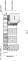
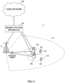
- a radio communication system 1 includes a radio base station 11 that forms a macro cell Cl, and radio base stations 12a and 12b that form small cells C2, which are placed inside the macro cell Cl and narrower than the macro cell Cl. Also, in the macro cell Cl and in each small cell C2, user terminals 20 are placed. The user terminals 20 are configured to be able to perform radio communication with both the radio base station 11 and radio base stations 12.
- the radio base station 11 and each radio base station 12 are connected with a higher station apparatus 30, and are connected with a core network 40 via the higher station apparatus 30.
- the higher station apparatus 30 may be, for example, an access gateway apparatus, a radio network controller (RNC), a mobility management entity (MME) and so on, but is by no means limited to these.
- RNC radio network controller
- MME mobility management entity
- each radio base station 12 may be connected with the higher station apparatus via the radio base station 11.
- the radio base stations 12a and 12b use enhanced PDCCHs that are frequency-division-multiplexed with the PDSCH from the top OFDM symbol of the subframe, and do not use the PDCCH. Note that, as shown in FIGs. 12B and 12C , to prevent interference between the radio base stations 12, in frequency resources where enhanced PDCCHs (primary) are placed in one radio base station 12, muting resources are placed in the other radio base station 12 (see FIG. 12C ).
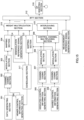
- FIG. 14 is a diagram to show an overall structure of a user terminal 20 according to the present embodiment.
- the user terminal 20 has a plurality of transmitting/receiving antennas 201 for MIMO transmission, amplifying sections 202, transmitting/receiving sections (receiving sections) 203, a baseband signal processing section 204, and an application section 205.
- the radio base station 10 has a higher layer control information generating section 300, a data generating section 301, a channel coding section 302, a modulation section 303, a mapping section 304, a downlink control information generating section 305, a shared control information generating section 306, channel coding sections 307, modulation sections 308, a control channel multiplexing section 309, an interleaving section 310, a measurement reference signal generating section 311, an IFFT section 312, a mapping section 313, a demodulation reference signal generating section 314, a weight multiplication section 315, a CP inserting section 316, and a scheduling section 317.
- the control channel multiplexing section 309 and the interleaving section 310 may be omitted.
- the higher layer control information generating section 300 generates higher layer control information on a per user terminal 20 basis. Also, the higher layer control information is control information that is sent through higher layer signaling (for example, RRC signaling) and includes, for example, enhanced PDCCH set allocation information (to be described later).
- the data generating section 301 generates downlink user data per user terminal 20.
- the downlink user data that is generated in the data generating section 301 and the higher layer control information that is generated in the higher layer control information generating section 300 are input in the channel coding section 302 as downlink data to be transmitted in the PDSCH.
- the channel coding section 302 performs channel coding of the downlink data for each user terminal 20 in accordance with the coding rate determined based on feedback information from each user terminal 20.
- the modulation section 303 modulates the downlink data having been subjected to channel coding, in accordance with the modulation scheme determined based on feedback information from each user terminal 20.
- the mapping section 304 maps the modulated downlink data in accordance with commands from the scheduling section 317.
- the downlink control information generating section 305 generates UE-specific downlink control information on a per user terminal 20 basis.
- the UE-specific downlink control information includes PDSCH allocation information (DL grants, DCI formats 1A and 1C and so on), and PUSCH allocation information (UL grants, DCI formats 0 and 4 and so on).
- the shared control information generating section 306 generates shared (cell-specific) control information that is shared between cells.
- the cell-shared control information includes, for example, control information for DCI formats 1A and 1.
- the downlink control information generated in the downlink control information generating section 305 and the shared control information generated in the shared control information generating section 306 are input in the channel coding sections 307 as downlink control information to be transmitted in the PDCCH or enhanced PDCCHs.
- the channel coding sections 307 perform channel coding of the downlink control information received as input, in accordance with the coding rate designated by a scheduling section 317, which will be described later.
- the modulation sections 308 modulate the downlink control information having been subjected to channel coding, in accordance with the modulation scheme designated by the scheduling section 317.
- the mapped downlink control information is input in the weight multiplication section 315 with the downlink data transmitted in the PDSCH (that is, the downlink data that is mapped in the mapping section 304) and the demodulation reference signals (DM-RSs) generated in the demodulation reference signal generating section 314.
- the weight multiplication section 315 multiplies the downlink data to be transmitted by the PDCSH, the downlink control information to be transmitted by the enhanced PDCCHs and the demodulation reference signals, by user terminal 20-specific precoding weights, and pre-encodes them. Also, when using a shared DM-RS, a precoding weight that is common between user terminals is used.
- the scheduling section 317 schedules the downlink data to be transmitted by the PDSCH, the downlink control information to be transmitted by the enhanced PDCCHs, and the downlink control information to be transmitted by the PDCCH. To be more specific, the scheduling section 317 allocates radio resources based on command information from the higher station apparatus 30 and feedback information from each user terminal 20 (for example, CSI (Channel State Information), which includes CQIs (Channel Quality Indicators) and RIs (Rank Indicators)).
- CSI Channel State Information
- CQIs Channel Quality Indicators
- RIs Rank Indicators
- the scheduling section 317 allocates a plurality of enhanced PDCCH sets (frequency resource sets) to each user terminal 20 so that at least part of the enhanced PDCCH sets overlap with other user terminal UEs.
- each enhanced PDCCH set is constituted to include a plurality of PRB pairs (frequency resource units) that are provided for the enhanced PDCCHs, and each PDCCH set is formed with different PRB pairs.
- the frequency resource units forming each enhanced PDCCH set are not limited to PRB pairs, and may be PRBs or RBGs.
- the allocation section and the reporting section of the present invention are configured with this scheduling section 317.
- the scheduling section 317 selects enhanced PDCCH sets from the enhanced PDCCH sets allocated to each user terminal 20 so that the number of enhanced PDCCH sets used to transmit downlink control information (DCI) in a given subframe (for example, an arbitrary time resource unit such as 1 ms) becomes minimum.
- the scheduling section 317 commands the mapping section 313 to map the downlink control information (DCI) to the PRB pairs constituting the selected enhanced PDCCH sets.
- the mapping section of the present invention is configured with the scheduling section 317 and the mapping section 313.
- the scheduling section 317 may command the mapping section 304 to map the downlink control information using distributed mapping, or may command the mapping section 304 to map the downlink control information using localized mapping. Also, whether or not to use distributed mapping or localized mapping may be changed per enhanced PDCCH set.
- Downlink signals received from the radio base station 10 as received data have the cyclic prefixes (CPs) removed in the CP removing section 401.
- the downlink signals, from which the CPs have been removed, are input in the FFT section 402.
- the FFT section 402 performs a fast Fourier transform (FFT) on the downlink signals, converts the time domain signals into frequency domain signals, and inputs these signals in the demapping section 403.
- the demapping section 403 demaps the downlink signals. Note that the demapping process by the demapping section 403 is performed based on higher layer control information that is received as input from the application section 205. Downlink control information that is output from the demapping section 403 is deinterleaved in the deinterleaving section 404.
- the enhanced PDCCH demodulation section 407 blind-decodes the candidate search spaces of a plurality of enhanced PDCCH sets based on the allocation information reported from the radio base station 10, and acquires the DCI for this user terminal.
- the enhanced PDCCH sets where the DCI is mapped are selected by the radio base station 10 so that the enhanced PDCCH sets used to transmit DCI in a given subframe become minimum.
- the channel estimation section 408 performs channel estimation using demodulation reference signals (DM-RSs), measurement reference signals (CRSs and CSI-RSs) and so on.
- the channel estimation section 408 outputs the result of channel estimation by the measurement reference signals (CRSs and CSI-RSs) to the PDCCH demodulation section 405.
- the channel estimation section 408 outputs the result of channel estimation by the demodulation reference signals (DM-RSs) to the PDSCH demodulation section 406 and the enhanced PDCCH demodulation section 407.
- DM-RSs demodulation reference signals
- the radio base station 10 allocates a plurality of enhanced PDCCH sets to each user terminal 20 so that at least one enhanced PDCCH set overlaps with other user terminals 20. Also, the radio base station 10 selects enhanced PDCCH sets so that the enhanced PDCCH sets to use to transmit DCI in a given subframe become minimum, and maps DCI to the PRB pairs that constitute the selected enhanced PDCCH sets. Consequently, when the number of user terminal UEs for which DCI is transmitted in a given subframe is small, it is possible to prevent the degradation of the efficiency of use of radio resources due to a decreased number of PRB pairs to which the PDSCH can be mapped.
Landscapes
- Engineering & Computer Science (AREA)
- Signal Processing (AREA)
- Computer Networks & Wireless Communication (AREA)
- Mobile Radio Communication Systems (AREA)
Applications Claiming Priority (3)
| Application Number | Priority Date | Filing Date | Title |
|---|---|---|---|
| JP2012107921A JP5809103B2 (ja) | 2012-05-09 | 2012-05-09 | 無線基地局、ユーザ端末、無線通信システム及び無線通信方法 |
| EP13787269.3A EP2849510B1 (en) | 2012-05-09 | 2013-05-09 | Wireless base station, user terminal, wireless communications system, and wireless communications method |
| PCT/JP2013/062993 WO2013168750A1 (ja) | 2012-05-09 | 2013-05-09 | 無線基地局、ユーザ端末、無線通信システム及び無線通信方法 |
Related Parent Applications (2)
| Application Number | Title | Priority Date | Filing Date |
|---|---|---|---|
| EP13787269.3A Division EP2849510B1 (en) | 2012-05-09 | 2013-05-09 | Wireless base station, user terminal, wireless communications system, and wireless communications method |
| EP13787269.3A Division-Into EP2849510B1 (en) | 2012-05-09 | 2013-05-09 | Wireless base station, user terminal, wireless communications system, and wireless communications method |
Publications (2)
| Publication Number | Publication Date |
|---|---|
| EP3780827A1 EP3780827A1 (en) | 2021-02-17 |
| EP3780827B1 true EP3780827B1 (en) | 2025-04-09 |
Family
ID=49550783
Family Applications (2)
| Application Number | Title | Priority Date | Filing Date |
|---|---|---|---|
| EP20198034.9A Active EP3780827B1 (en) | 2012-05-09 | 2013-05-09 | Radio base station, user terminal, radio communication system and radio communication method |
| EP13787269.3A Active EP2849510B1 (en) | 2012-05-09 | 2013-05-09 | Wireless base station, user terminal, wireless communications system, and wireless communications method |
Family Applications After (1)
| Application Number | Title | Priority Date | Filing Date |
|---|---|---|---|
| EP13787269.3A Active EP2849510B1 (en) | 2012-05-09 | 2013-05-09 | Wireless base station, user terminal, wireless communications system, and wireless communications method |
Country Status (7)
Families Citing this family (26)
| Publication number | Priority date | Publication date | Assignee | Title |
|---|---|---|---|---|
| CN110505044B (zh) | 2013-01-29 | 2022-03-01 | 太阳专利托管公司 | 通信装置及通信方法 |
| EP3041154B1 (en) * | 2013-08-29 | 2021-05-05 | LG Electronics Inc. | Method and device for transmitting channel state information in wireless access system supporting machine type communication |
| US10292143B2 (en) * | 2015-04-09 | 2019-05-14 | Intel IP Corporation | Methods, apparatuses, and systems for enhancement of evolved physical downlink control channel for machine type communications |
| US10652768B2 (en) | 2015-04-20 | 2020-05-12 | Qualcomm Incorporated | Control channel based broadcast messaging |
| US10129101B2 (en) * | 2015-04-30 | 2018-11-13 | Futurewei Technologies, Inc. | Application driven and adaptive unified resource management for data centers with Multi-Resource Schedulable Unit (MRSU) |
| CN107006041B (zh) * | 2015-08-14 | 2020-02-14 | 华为技术有限公司 | 下行控制信息的接收、发送方法及装置 |
| US10425200B2 (en) | 2016-04-13 | 2019-09-24 | Qualcomm Incorporated | System and method for beam adjustment request |
| US10069555B2 (en) | 2016-04-13 | 2018-09-04 | Qualcomm Incorporated | System and method for beam management |
| US10615862B2 (en) | 2016-04-13 | 2020-04-07 | Qualcomm Incorporated | System and method for beam adjustment request |
| RU2759693C2 (ru) * | 2016-07-29 | 2021-11-16 | Нтт Докомо, Инк. | Пользовательский терминал, способ радиосвязи и система связи |
| US10582397B2 (en) * | 2016-11-09 | 2020-03-03 | Qualcomm Incorporated | Beam refinement reference signal transmissions during control symbol |
| CN108235340B (zh) * | 2016-12-21 | 2021-08-20 | 展讯通信(上海)有限公司 | 下行调度方法、装置及基站 |
| MX2019007209A (es) * | 2016-12-26 | 2019-08-16 | Guangdong Oppo Mobile Telecommunications Corp Ltd | Procedimiento de comunicaciones inalambricas, dispositivo de red y dispositivo terminal. |
| CN108271259B (zh) | 2016-12-30 | 2023-10-24 | 华为技术有限公司 | 控制信道的资源指示方法、用户设备和网络设备 |
| US10368353B2 (en) * | 2017-01-27 | 2019-07-30 | Qualcomm Incorporated | Adaptive subcarrier spacing configuration |
| CN108401292B (zh) * | 2017-02-04 | 2023-07-18 | 中兴通讯股份有限公司 | 控制信息的传输方法、接收方法、装置、基站及终端 |
| US11122552B2 (en) * | 2017-02-06 | 2021-09-14 | Apple Inc. | Downlink control signaling segmentation |
| CN108419293B (zh) * | 2017-02-10 | 2021-05-18 | 华为技术有限公司 | 传输下行控制信息的方法和装置 |
| BR112020001618A2 (pt) * | 2017-07-28 | 2020-07-21 | Ntt Docomo, Inc. | terminal e método de radiocomunicação para um terminal |
| CN109391962B (zh) | 2017-08-11 | 2022-02-25 | 华为技术有限公司 | 通信方法及通信装置 |
| CN109756949B (zh) * | 2017-08-22 | 2021-01-22 | 大唐移动通信设备有限公司 | 一种资源分配方法和装置 |
| PT3627927T (pt) * | 2017-09-07 | 2023-06-06 | Guangdong Oppo Mobile Telecommunications Corp Ltd | Método e dispositivo de transmissão de informações |
| US11510193B2 (en) | 2017-09-13 | 2022-11-22 | Qualcomm Incorporated | Techniques for establishing a beam pair link |
| KR102808691B1 (ko) * | 2018-05-11 | 2025-05-20 | 한국전자통신연구원 | 고신뢰 및 저지연 통신을 위한 신호의 송수신 방법 |
| CN114175745A (zh) * | 2019-05-02 | 2022-03-11 | 瑞典爱立信有限公司 | 稳健的ue自主天线自适应 |
| US11870626B1 (en) * | 2022-07-25 | 2024-01-09 | Qualcomm Incorporated | Multi-cluster low peak to average power ratio waveform design |
Family Cites Families (9)
| Publication number | Priority date | Publication date | Assignee | Title |
|---|---|---|---|---|
| CN104301081B (zh) | 2007-10-29 | 2018-06-15 | 奥普蒂斯无线技术有限责任公司 | 终端和基站装置、响应信号发送和接收方法以及集成电路 |
| WO2010013960A2 (en) * | 2008-07-31 | 2010-02-04 | Samsung Electronics Co., Ltd. | Method and apparatus for allocating resource of multiple carriers in ofdma system |
| US9215705B2 (en) * | 2010-03-30 | 2015-12-15 | Lg Electronics Inc. | Method and apparatus for monitoring control channel in wireless communication system |
| US9014081B2 (en) * | 2010-04-09 | 2015-04-21 | Futurewei Technologies, Inc. | System and method for transmitting control information |
| JP2012107921A (ja) | 2010-11-16 | 2012-06-07 | Seiko Epson Corp | 受信信号判定方法、プログラム、測位装置、及び電子機器 |
| KR102109408B1 (ko) * | 2011-04-03 | 2020-05-26 | 엘지전자 주식회사 | 무선 통신 시스템에서 하향링크 제어 채널을 송수신하는 방법 및 장치 |
| WO2012144801A2 (ko) * | 2011-04-18 | 2012-10-26 | 엘지전자 주식회사 | 무선통신시스템에서 신호 전송 방법 및 장치 |
| CN102404076B (zh) * | 2011-11-07 | 2014-12-10 | 电信科学技术研究院 | 信息发送及盲检方法和设备 |
| CN102395206B (zh) * | 2011-11-08 | 2015-07-15 | 电信科学技术研究院 | 下行控制信息的传输方法和设备 |
-
2012
- 2012-05-09 JP JP2012107921A patent/JP5809103B2/ja active Active
-
2013
- 2013-05-09 CN CN201380024327.6A patent/CN104335651B/zh active Active
- 2013-05-09 MX MX2014013506A patent/MX343731B/es active IP Right Grant
- 2013-05-09 EP EP20198034.9A patent/EP3780827B1/en active Active
- 2013-05-09 US US14/398,985 patent/US9756622B2/en active Active
- 2013-05-09 EP EP13787269.3A patent/EP2849510B1/en active Active
- 2013-05-09 ES ES13787269T patent/ES2838198T3/es active Active
- 2013-05-09 WO PCT/JP2013/062993 patent/WO2013168750A1/ja active Application Filing
Also Published As
| Publication number | Publication date |
|---|---|
| EP3780827A1 (en) | 2021-02-17 |
| EP2849510A1 (en) | 2015-03-18 |
| CN104335651A (zh) | 2015-02-04 |
| JP5809103B2 (ja) | 2015-11-10 |
| CN104335651B (zh) | 2018-07-03 |
| MX2014013506A (es) | 2015-10-22 |
| EP2849510A4 (en) | 2016-01-06 |
| JP2013236278A (ja) | 2013-11-21 |
| US20150110031A1 (en) | 2015-04-23 |
| WO2013168750A1 (ja) | 2013-11-14 |
| EP2849510B1 (en) | 2020-11-25 |
| ES2838198T3 (es) | 2021-07-01 |
| MX343731B (es) | 2016-11-18 |
| US9756622B2 (en) | 2017-09-05 |
Similar Documents
| Publication | Publication Date | Title |
|---|---|---|
| EP3780827B1 (en) | Radio base station, user terminal, radio communication system and radio communication method | |
| US9763240B2 (en) | Blind decoding method, radio base station, user terminal and radio communication system | |
| US9893863B2 (en) | Determining UL radio resources for delivery acknowledgement information of a DSCH when a plurality of resource sets of an enhanced DCCH are configured | |
| EP2903371B1 (en) | Radio base station, user terminal, radio communication system, and radio communication method | |
| US9380570B2 (en) | Radio base station apparatus, user terminal, radio communication system and radio communication method | |
| US9408204B2 (en) | Radio base station apparatus, user terminal, radio communication system and radio communication method | |
| US9491749B2 (en) | Radio communication method, radio communication system and radio base station | |
| US20150016370A1 (en) | Radio base station apparatus, user terminal, radio communication system and radio communication method | |
| US9882694B2 (en) | Radio base station, user terminal, radio communication system and radio communication method | |
| JP6068860B2 (ja) | 無線通信方法、無線基地局、ユーザ端末及び無線通信システム | |
| JP6106725B2 (ja) | 無線基地局、ユーザ端末、無線通信システム及び無線通信方法 |
Legal Events
| Date | Code | Title | Description |
|---|---|---|---|
| PUAI | Public reference made under article 153(3) epc to a published international application that has entered the european phase |
Free format text: ORIGINAL CODE: 0009012 |
|
| STAA | Information on the status of an ep patent application or granted ep patent |
Free format text: STATUS: REQUEST FOR EXAMINATION WAS MADE |
|
| 17P | Request for examination filed |
Effective date: 20200924 |
|
| AC | Divisional application: reference to earlier application |
Ref document number: 2849510 Country of ref document: EP Kind code of ref document: P |
|
| AK | Designated contracting states |
Kind code of ref document: A1 Designated state(s): AL AT BE BG CH CY CZ DE DK EE ES FI FR GB GR HR HU IE IS IT LI LT LU LV MC MK MT NL NO PL PT RO RS SE SI SK SM TR |
|
| RAP3 | Party data changed (applicant data changed or rights of an application transferred) |
Owner name: NTT DOCOMO, INC. |
|
| STAA | Information on the status of an ep patent application or granted ep patent |
Free format text: STATUS: EXAMINATION IS IN PROGRESS |
|
| 17Q | First examination report despatched |
Effective date: 20221215 |
|
| P01 | Opt-out of the competence of the unified patent court (upc) registered |
Effective date: 20230517 |
|
| GRAP | Despatch of communication of intention to grant a patent |
Free format text: ORIGINAL CODE: EPIDOSNIGR1 |
|
| STAA | Information on the status of an ep patent application or granted ep patent |
Free format text: STATUS: GRANT OF PATENT IS INTENDED |
|
| RIC1 | Information provided on ipc code assigned before grant |
Ipc: H04W 72/23 20230101ALN20241107BHEP Ipc: H04W 72/0453 20230101ALN20241107BHEP Ipc: H04L 5/00 20060101ALN20241107BHEP Ipc: H04W 72/12 20090101ALI20241107BHEP Ipc: H04W 72/04 20090101AFI20241107BHEP |
|
| INTG | Intention to grant announced |
Effective date: 20241203 |
|
| RAP3 | Party data changed (applicant data changed or rights of an application transferred) |
Owner name: NTT DOCOMO, INC. |
|
| GRAS | Grant fee paid |
Free format text: ORIGINAL CODE: EPIDOSNIGR3 |
|
| GRAA | (expected) grant |
Free format text: ORIGINAL CODE: 0009210 |
|
| STAA | Information on the status of an ep patent application or granted ep patent |
Free format text: STATUS: THE PATENT HAS BEEN GRANTED |
|
| AC | Divisional application: reference to earlier application |
Ref document number: 2849510 Country of ref document: EP Kind code of ref document: P |
|
| AK | Designated contracting states |
Kind code of ref document: B1 Designated state(s): AL AT BE BG CH CY CZ DE DK EE ES FI FR GB GR HR HU IE IS IT LI LT LU LV MC MK MT NL NO PL PT RO RS SE SI SK SM TR |
|
| REG | Reference to a national code |
Ref country code: GB Ref legal event code: FG4D |
|
| REG | Reference to a national code |
Ref country code: CH Ref legal event code: EP |
|
| REG | Reference to a national code |
Ref country code: DE Ref legal event code: R096 Ref document number: 602013086674 Country of ref document: DE |
|
| REG | Reference to a national code |
Ref country code: IE Ref legal event code: FG4D |
|
| REG | Reference to a national code |
Ref country code: NL Ref legal event code: FP |
|
| PGFP | Annual fee paid to national office [announced via postgrant information from national office to epo] |
Ref country code: NL Payment date: 20250522 Year of fee payment: 13 |
|
| PGFP | Annual fee paid to national office [announced via postgrant information from national office to epo] |
Ref country code: DE Payment date: 20250520 Year of fee payment: 13 |
|
| PGFP | Annual fee paid to national office [announced via postgrant information from national office to epo] |
Ref country code: GB Payment date: 20250522 Year of fee payment: 13 |
|
| PGFP | Annual fee paid to national office [announced via postgrant information from national office to epo] |
Ref country code: IE Payment date: 20250411 Year of fee payment: 13 |