EP3780751B1 - Procédé et dispositif d'indication d'informations, et support d'informations d'ordinateur - Google Patents
Procédé et dispositif d'indication d'informations, et support d'informations d'ordinateur Download PDFInfo
- Publication number
- EP3780751B1 EP3780751B1 EP18912512.3A EP18912512A EP3780751B1 EP 3780751 B1 EP3780751 B1 EP 3780751B1 EP 18912512 A EP18912512 A EP 18912512A EP 3780751 B1 EP3780751 B1 EP 3780751B1
- Authority
- EP
- European Patent Office
- Prior art keywords
- synchronization raster
- frequency band
- ssb
- synchronization
- formula
- Prior art date
- Legal status (The legal status is an assumption and is not a legal conclusion. Google has not performed a legal analysis and makes no representation as to the accuracy of the status listed.)
- Active
Links
Images


Classifications
-
- H—ELECTRICITY
- H04—ELECTRIC COMMUNICATION TECHNIQUE
- H04W—WIRELESS COMMUNICATION NETWORKS
- H04W56/00—Synchronisation arrangements
- H04W56/001—Synchronization between nodes
-
- H—ELECTRICITY
- H04—ELECTRIC COMMUNICATION TECHNIQUE
- H04J—MULTIPLEX COMMUNICATION
- H04J11/00—Orthogonal multiplex systems, e.g. using WALSH codes
- H04J11/0069—Cell search, i.e. determining cell identity [cell-ID]
-
- H—ELECTRICITY
- H04—ELECTRIC COMMUNICATION TECHNIQUE
- H04W—WIRELESS COMMUNICATION NETWORKS
- H04W48/00—Access restriction; Network selection; Access point selection
- H04W48/08—Access restriction or access information delivery, e.g. discovery data delivery
- H04W48/10—Access restriction or access information delivery, e.g. discovery data delivery using broadcasted information
-
- H—ELECTRICITY
- H04—ELECTRIC COMMUNICATION TECHNIQUE
- H04W—WIRELESS COMMUNICATION NETWORKS
- H04W48/00—Access restriction; Network selection; Access point selection
- H04W48/16—Discovering, processing access restriction or access information
-
- H—ELECTRICITY
- H04—ELECTRIC COMMUNICATION TECHNIQUE
- H04W—WIRELESS COMMUNICATION NETWORKS
- H04W56/00—Synchronisation arrangements
-
- H—ELECTRICITY
- H04—ELECTRIC COMMUNICATION TECHNIQUE
- H04W—WIRELESS COMMUNICATION NETWORKS
- H04W72/00—Local resource management
- H04W72/04—Wireless resource allocation
- H04W72/044—Wireless resource allocation based on the type of the allocated resource
- H04W72/0453—Resources in frequency domain, e.g. a carrier in FDMA
-
- H—ELECTRICITY
- H04—ELECTRIC COMMUNICATION TECHNIQUE
- H04W—WIRELESS COMMUNICATION NETWORKS
- H04W72/00—Local resource management
- H04W72/20—Control channels or signalling for resource management
Definitions
- the present disclosure relates to the field of wireless communication technology, and more particularly to a method and device for information indication, and a computer storage medium.
- the access system is a licensed carrier system or an unlicensed carrier system based on the received Synchronization Signal Block (SSB).
- SSB Synchronization Signal Block
- EP 3 755 027 A1 relates to a communication method for determining the working frequency band attribute or system attribute of the network device.
- a method for information indication is provided by an embodiment of the present disclosure, which includes operations as follows.
- a terminal device receives a synchronization signal block (SSB) sent by a network device.
- SSB synchronization signal block
- the terminal device acquires indication information according to frequency domain position information of the SSB, and the indication information is used to indicate an attribute of a carrier associated with the SSB, and the attribute of the carrier includes whether the carrier is used by a licensed carrier system or an unlicensed carrier system.
- the operation that the terminal device acquires indication information according to the frequency domain position information of the SSB includes operations as follows.
- the terminal device acquires the indication information according to a position of a synchronization raster where the detected SSB is located.
- the terminal device in response to detecting that the SSB is located at a position of a first synchronization raster, determines that the carrier associated with the SSB is used by a licensed carrier system.
- the terminal device determines that the carrier associated with the SSB is used by an unlicensed carrier system.
- the method further includes operation as follows.
- the terminal device determines the position of the first synchronization raster based on a first set of formulas.
- the terminal device determines the position of the second synchronization raster based on a second set of formulas.
- the position of the first synchronization raster determined by the first set of formulas and the position of the second synchronization raster determined by the second set of formulas meet the following relationship: the first synchronization raster and the second synchronization raster have synchronization rasters at different positions within an overlapping bandwidth of a first frequency band and a second frequency band.
- the first frequency band is a licensed spectrum and the second frequency band is an unlicensed spectrum.
- O1, O2 and O3 denote synchronization raster offsets.
- the operation that the terminal device determines the position of the first synchronization raster based on the first set of formulas includes operations as follows.
- a method for information indication is provided by an embodiment of the present disclosure, which includes operations as follows.
- a network device transmits a synchronization signal block (SSB) to a terminal device, so that the terminal device acquires indication information according to frequency domain position information of the SSB.
- the indication information is used to indicate an attribute of a carrier associated with the SSB, and the attribute of the carrier includes whether the carrier is used by a licensed carrier system or an unlicensed carrier system.
- the operation that the network device transmits the SSB to the terminal device includes operations as follows.
- the network device transmits an SSB to the terminal device in a position of a first synchronization raster, so that the terminal device detects that the SSB is located at the position of the first synchronization raster to determine that the carrier associated with the SSB is used by a licensed carrier system.
- the network device transmits an SSB to the terminal device in a position of a second synchronization raster, so that the terminal device detects that the SSB is located at the position of the second synchronization raster to determine that the carrier associated with the SSB is used by an unlicensed carrier system.
- the method further includes operations as follows.
- the network device determines the position of the first synchronization raster based on a first set of formulas.
- the network device determines the position of the second synchronization raster based on a second set of formulas.
- the position of the first synchronization raster determined by the first set of formulas and the position of the second synchronization raster determined by the second set of formulas meet the following relationship: the first synchronization raster and the second synchronization raster have synchronization rasters at different positions within an overlapping bandwidth of a first frequency band and a second frequency band.
- the first frequency band is a licensed spectrum and the second frequency band is an unlicensed spectrum.
- the network device determines the position of the second synchronization raster based on the second set of formulas includes operations as follows.
- O1, O2, and O3 denote synchronization raster offsets.
- the operation that the network device determines the position of the first synchronization raster based on the first set of formulas includes operations as follows.
- a device for information indication is provided by an embodiment of the present disclosure, which includes a receiving unit and an acquiring unit.
- the receiving unit is configured to receive a synchronization signal block (SSB) sent by a network device.
- SSB synchronization signal block
- the acquiring unit is configured to acquire indication information according to frequency domain position information of the SSB, and the indication information is used to indicate an attribute of a carrier associated with the SSB, and the attribute of the carrier includes whether the carrier is used by a licensed carrier system or an unlicensed carrier system.
- the acquiring unit is configured to acquire the indication information according to a position of a synchronization raster where the detected SSB is located.
- the device further includes a determining unit.
- the determining unit is configured to determine that the carrier associated with the SSB is used by the licensed carrier system in response to detecting that the SSB is located at a position of a first synchronization raster; and determine that the carrier associated with the SSB is used by the unlicensed carrier system in response to detecting that that the SSB is located at a position of a second synchronization raster.
- the determining unit includes a first determining subunit and a second determining subunit.
- the first determining subunit is configured to determine the position of the first synchronization raster based on a first set of formulas.
- the second determining subunit is configured to determine the position of the second synchronization raster based on a second set of formulas.
- the position of the first synchronization raster determined by the first set of formulas and the position of the second synchronization raster determined by the second set of formulas meet the following relationship: the first synchronization raster and the second synchronization raster have synchronization rasters at different positions within an overlapping bandwidth of a first frequency band and a second frequency band.
- the first frequency band is a licensed spectrum and the second frequency band is an unlicensed spectrum.
- the second determining subunit is configured to perform operations as follows.
- the transmitting unit is configured to transmit an SSB to the terminal device in a position of a first synchronization raster, so that the terminal device detects that the SSB is located in the position of the first synchronization raster to determine that the carrier associated with the SSB is used by the licensed carrier system; and transmit an SSB to the terminal device in a position of a second synchronization raster, so that the terminal device detects that the SSB is located in the position of the second synchronization raster to determine that the carrier associated with the SSB is used by the unlicensed carrier system
- the device further includes a determining unit.
- the determining unit includes a first determining subunit and a second determining subunit.
- the first determining subunit is configured to determine the position of the first synchronization raster based on a first set of formulas.
- the second determining subunit is configured to determine the position of the second synchronization raster based on a second set of formulas.
- the position of the first synchronization raster determined by the first set of formulas and the position of the second synchronization raster determined by the second set of formulas meet the following relationship: the first synchronization raster and the second synchronization raster have synchronization rasters at different positions within an overlapping bandwidth of a first frequency band and a second frequency band.
- the first frequency band is a licensed spectrum and the second frequency band is an unlicensed spectrum.
- the second determining subunit is configured to perform operations as follows.
- O1, O2, and O3 denote synchronization raster offsets.
- the first determining subunit is configured to perform operations as follows.
- the computer storage medium having stored thereon computer executable instructions is provided by the embodiments of the present disclosure.
- the computer executable instructions are executed by the processor, the above method for information indication is implemented.
- the terminal device receives an SSB transmitted by the network device, and the terminal device acquires indication information according to frequency domain position information of the SSB.
- the indication information is used to indicate an attribute of a carrier associated with the SSB, and the attribute of the carrier includes whether the carrier is used by a licensed carrier system or an unlicensed carrier system.
- the terminal device when detecting the SSB, can acquires whether the carrier associated with the SSB is used by an licensed carrier system (such as a NR licensed system) or an unlicensed carrier system (such as a NR unlicensed system), thereby correctly performing transmission and reception of subsequent signals, and avoiding further blind detection and reducing signaling overhead.
- a feasible method is to form a beam by using the beamforming technology through a multi-antenna system of a base station, to improve a gain of the wireless signal and remedy the path loss.
- the beam is directional, and a narrow beam can only cover a part area of the cell, and cannot cover all users in the cell.
- the base station can transmit signals through four beams in different directions.
- Beam B2 can only cover User Equipment (UE) 1, and cannot cover UE2.
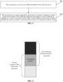
- Multi-beam transmission of Synchronization Signal is implemented by defining an SS burst set.
- the SS burst set contains one or more SS bursts, and an SS burst contains one or more SS Blocks (also referred to as SSB).
- the SS block is used to carry a synchronization signal and a broadcast channel of a beam. Therefore, the SS burst set can contain the synchronization signals of the beams, the number of beams is equal to the number of SS blocks in the cell.
- the SS block contains a Primary Synchronization Signal (PSS) of one symbol, a Secondary Synchronization Signal (SSS) of one symbol, and New Radio access Technology-Physical Broadcast Channel (NR-PBCH) of two symbols, as shown in FIG. 2 .
- PSS Primary Synchronization Signal
- SSS Secondary Synchronization Signal
- NR-PBCH New Radio access Technology-Physical Broadcast Channel
- a period of the SS burst set is configurable, and the SS burst set transmitted within one period is transmitted within a time window of 5ms. Taking a sub-carrier interval of 15kHz as an example, a slot contains 14 symbols and can carry two SS blocks.
- RMSI Remaining Minimum System Information
- paging messages also need to be transmitted by multi-beam scanning.
- the UE When the UE needs to access the network, the UE obtains system messages from the network, a part of which is carried by the NR-PBCH and a part of which is carried by the NR-PDSCH.
- the system message carried by the NR-PDSCH includes RMSI.
- Downlink Control Information (DCI) corresponding to the NR-PDSCH is carried by the NR-PDCCH, and a location of a time-frequency resource where the NR-PDCCH is arranged is indicated by CORESET information carried by the NR-PBCH, that is, Type0-PDCCH common search space information.
- DCI Downlink Control Information
- the NR-PBCH also carries information, that is, RMSI presence flag information, for indicating whether the SS block is associated with the RMSI or the Type0-PDCCH common search space.
- the RMSI presence flag information indicates that the current SS block is not associated with RMSI or Type0-PDCCH common search space through a reserved value in the PRB grid offset information field.
- the PRB grid offset information field includes 4 or 5 bits, which is used to indicate an offset between physical resource block (PRB) grids between channels or signals of the synchronous signal block and the non-synchronous signal block.
- the offset includes 0-11 or 0-23 subcarriers. Therefore, the PRB grid offset information field further includes 4 or 8 reserved values for indicating that the current SS block is not associated with the RMSI or the Type0-PDCCH common search space.
- RMSI-PDCCH-Config information is indicated by 8 bits.
- the RMSI-PDCCH-Config information field is used to indicate frequency domain position information of the synchronization signal block, for reducing blind detection performed by the UE.
- the PBCH in the synchronization signal block is detected according to the frequency domain position information of the synchronization signal block, to acquire the RMSI-PDCCH-Config information, and further receive the RMSI.
- the frequency domain position of the synchronization signal block is defined by the synchronization raster, as shown in Table 1 below.
- possible frequency domain positions of the synchronization signal block are determined by the formula in Table 1 and are numbered by SSREF.
- resource mapping of the synchronization signal block is determined according to Table 2 below. That is, the synchronization raster is located in a RE numbered 0 of a PRB numbered 10 of 20 PRBs of the synchronization signal block.
- a distribution of the synchronization rasters in different frequency bands is determined by Table 3 below.
- the number of the synchronization raster ranges from 9460 to 10079, there is a total of 620 synchronization rasters.
- frequency domain location information of the second SSB (the current SSB is the first SSB) is indicated by the bit in the RMSI-PDCCH-Config information field. Since the RMSI-PDCCH-Config information field contains 8 bits, positions of 256 synchronization rasters can be indicated by indicating an offset of a target synchronization raster relative to a synchronization raster corresponding to the current synchronization signal block. The positions of N ⁇ 265 synchronization rasters can be indicated based on different reserved values in the PRB grid offset information field.
- an offset of a GSCN of the synchronization raster corresponding to the target SSB relative to the GSCN of the synchronized raster corresponding to the current SSB is indicated by k SSB and RMSI-PDCCH-Config, respectively according to Table 4 and Table 5.
- An indication range in Table 4 includes -768 ...-1, 1 ... 768, and an indication range in Table 5 includes -256 ...-1, 1 ... 256.
- N GSCN Reference ⁇ N GSCN Start , N GSCN Reference + N GSCN End , N GSCN Start and N GSCN End is determined according to the higher 4 bits and lower 4 bits of RMSI-PDCCH-Config.
- the terminal device may also be referred to as a User Equipment (UE), an access terminal, a user unit, a user station, a mobile station, a mobile radio station, a remote station, a remote terminal, a mobile device, a user terminal, a terminal, a wireless communication device, a user agent or a user device.
- UE User Equipment
- FIG. 3 is a first schematic flowchart of a method for information indication in an embodiment of the present disclosure. As shown in FIG. 3 , the method for information indication includes operations 301 and 302.
- a different method for calculating a position of a synchronization raster (sync raster) in the unlicensed band from that in the licensed band is set, to meet a condition that a position of a synchronization raster on the unlicensed band does not overlap with a position of a synchronization raster on the licensed band.
- the terminal device detects the SSB, the terminal device can determine that whether a carrier associated with SSB is used by a licensed carrier system or an unlicensed carrier system according to a position of a synchronization raster where the SSB is located.
- the terminal determines that the carrier associated with the SSB is used by a licensed carrier system. In response to detecting the SSB is located at a position of a second synchronization raster, the terminal device determines that the carrier associated with the SSB is used by an unlicensed carrier system.
- how the terminal device determines whether a synchronization raster where the detected SSB is located belongs to the first synchronization raster or the second synchronization raster can be implemented in the following manner.
- the terminal device determines the position of the first synchronization raster based on a first set of formulas.
- the position of the first synchronization raster determined by the first set of formulas and the position of the second synchronization raster determined by the second set of formulas meet the following relationship: the first synchronization raster and the second synchronization raster have synchronization rasters at different positions within an overlapping bandwidth between a first frequency band and a second frequency band.
- the first frequency band is a licensed spectrum and the second frequency band is an unlicensed spectrum.
- O1, O2, and O3 denote synchronization raster offsets.
- the position of the second synchronization raster is obtained by adding an offset to the position of the first synchronization raster, so that the first synchronization raster and the second synchronization raster do not overlap with each other.
- O1 450kHz
- O2 0.72MHz
- O3 8.64MHz. It should be understood that the values of O1, O2, and O3 are not unique.
- a new synchronization raster calculation formula can also be defined separately for the unlicensed band, which is different from the existing synchronization raster calculation formula.
- the position of the first synchronization raster corresponding to the first frequency band is shown by a solid line; and the position of the second synchronization raster corresponding to the second frequency band is shown by a dotted line. Since the first synchronization raster and the second synchronization raster are determined by different formulas, it can be ensured the positions of the synchronization rasters corresponding to the licensed band and the unlicensed band do not overlap in the overlapping portion of the first bandwidth and the second bandwidth.
- FIG. 6 is a second schematic flowchart of a method for information indication in an embodiment of the present disclosure. As shown in FIG. 6 , the method for information indication includes operations 601
- a network device transmits an SSB to a terminal device, so that the terminal device acquires indication information according to frequency domain position information of the SSB, and the indication information is used to indicate an attribute of a carrier associated with the SSB, and the attribute of the carrier includes whether the carrier is used by a licensed carrier system or an unlicensed carrier system.
- the attribute of the carrier associated with the SSB include whether the carrier is used by a licensed carrier system or an unlicensed carrier system.
- the attribute of the carrier associated with the SSB includes whether the SSB on the carrier is sent by a licensed carrier system or an unlicensed carrier system.
- the operation that the network device transmits an SSB to the terminal device includes operations as follows.
- the network device transmits an SSB to the terminal device in a position of a first synchronization raster, and the terminal device detects that the SSB is located at the position of the first synchronization raster to determine that the carrier associated with the SSB is used by the licensed carrier system.
- the network device transmits an SSB to the terminal device in a position of a second synchronization raster, and the terminal device detects that the SSB is located at a position of a second synchronization raster to determine that the carrier associated with the SSB is used by the unlicensed carrier system.
- the network device determines the position of the first synchronization raster based on a first set of formulas.
- the position of the first synchronization raster determined by the first set of formulas and the position of the second synchronization raster determined by the second set of formulas meets the following relationship: the first synchronization raster and the second synchronization raster have synchronization rasters at different positions within an overlapping bandwidth of the first frequency band and the second frequency band.
- the first frequency band is a licensed spectrum and the second frequency band is an unlicensed spectrum.
- the operation that the terminal device determines the position of the second synchronization raster based on the second set of formulas includes operations as follows.
- O1, O2, and O3 denote synchronization raster offsets.
- the operation that the terminal device determines the position of the first synchronization raster based on the first set of formulas includes operations as follows.
- FIG. 7 is a first schematic structural diagram of a device for information indication in an embodiment of the present disclosure.
- the device for information indication includes a receiving unit 701 and an acquiring unit 702.
- the receiving unit 701 is configured to receive an SSB transmitted by a network device.
- the acquiring unit 702 is configured to acquire indication information according to frequency domain position information of the SSB.
- the indication information is used to indicate an attribute of a carrier associated with the SSB, and the attribute of the carrier includes whether the carrier is used by a licensed carrier system or an unlicensed carrier system.
- the attribute of the carrier associated with the SSB includes whether the carrier is used by a licensed carrier system or an unlicensed carrier system. In other words, the attribute of the carrier associated with the SSB includes whether the SSB on the carrier is transmitted by a licensed carrier system or an unlicensed carrier system.
- the acquiring unit 702 is configured to acquire the indication information according to a position of a synchronization raster where the detected SSB is located.
- the device further includes a determining unit 703.
- the determining unit 703 is configured to determine that the carrier associated with the SSB is used by the licensed carrier system in response to that it is detected that the SSB is located at a position of a first synchronization raster, and determine that the carrier associated with the SSB is used by the unlicensed the carrier system in response to that it is detected that the SSB is located at a position of a second synchronization raster.
- the determining unit 703 includes a first determining subunit 7031 and a second determining subunit 7032.
- the first determining subunit 7031 is configured to determine the position of the first synchronization raster based on a first set of formulas.
- the second determining subunit 7032 is configured to determine the position of the second synchronization raster based on a second set of formulas.
- the position of the first synchronization raster determined by the first set of formulas and the position of the second synchronization raster determined by the second set of formulas meet the following relationship: the first synchronization raster and the second synchronization raster have synchronization rasters at different positions within an overlapping bandwidth of the first frequency band and the second frequency band.
- the first frequency band is a licensed spectrum and the second frequency band is an unlicensed spectrum.
- the second determining subunit 7032 is configured to perform the following operations.
- O1, O2, and O3 denote synchronization raster offsets.
- the first determining subunit 7031 is configured to perform operations as follows.
- each unit in the device for information indication shown in FIG. 7 can be understood by referring to related description of the above method for information indication.
- the function of each unit in the device for information indication shown in FIG. 7 may be implemented by a program running on a processor or a specific logic circuit.
- FIG. 8 is a second schematic structural diagram of a device for information indication in an embodiment of the present disclosure. As shown in FIG. 8 , the device for information indication includes a transmitting unit 801.
- the transmitting unit 801 is configured to transmit an SSB to a terminal device, so that the terminal device acquires indication information according to frequency domain position information of the SSB, and the indication information is used to indicate an attribute of a carrier associated with the SSB, and the attribute of the carrier includes whether the carrier is used by a licensed carrier system or an unlicensed carrier system.
- the attribute of the carrier associated with the SSB include whether the carrier is used by a licensed carrier system or an unlicensed carrier system.
- the attribute of the carrier associated with the SSB includes whether the SSB on the carrier is sent by a licensed carrier system or an unlicensed carrier system.
- the transmitting unit 801 is configured to transmit an SSB to the terminal device in a position of a first synchronization raster, so that the terminal device detects that the SSB is located in the position of the first synchronization raster to determine that the carrier associated with the SSB is used by the licensed carrier system; transmit an SSB to the terminal device in a position of a second synchronization raster, so that the terminal device detects that the SSB is located in the position of the second synchronization raster to determine that the carrier associated with the SSB is used by the unlicensed carrier system.
- the device further includes a determining unit 802.
- the determining unit 802 includes a first determining subunit 8021 and a second determining subunit 8022.
- the first determining subunit 8021 is configured to determine the position of the first synchronization raster based on a first set of formulas.
- the second determining subunit 8022 is configured to determine the position of the second synchronization raster based on a second set of formulas.
- the position of the first synchronization raster determined by the first set of formulas and the position of the second synchronization raster determined by the second set of formulas meets the following relationship: the first synchronization raster and the second synchronization raster have synchronization rasters at different positions within an overlapping bandwidth of the first frequency band and the second frequency band.
- the first frequency band is a licensed spectrum and the second frequency band is an unlicensed spectrum.
- the second determining subunit 8022 is configured to perform the following operations.
- O1, O2, and O3 denote synchronization raster offsets.
- the first determining subunit 8021 is configured to perform operations as follows.
- each unit in the device for information indication shown in FIG. 8 can be understood by referring to the related description of the above method for information indication.
- the function of each unit in the device for information indication shown in FIG. 8 may be implemented by a program running on a processor or a specific logic circuit.
- the above device for information indication in the embodiment of the present disclosure may be stored in a computer-readable storage medium.
- the essential parts of the technical solutions of the embodiments of the present disclosure or parts of the technical solutions of the embodiments of the disclosure making contributions to the conventional art may be embodied in form of software product, and the computer software product is stored in a storage medium, and includes a plurality of instructions configured to enable a computer device (which may be a personal computer, a server, a network device or the like) to execute all or a part of the method in each embodiment of the present disclosure.
- the above storage medium includes: various media capable of storing program codes such as a U disk, a mobile hard disk, a Read Only Memory (ROM), a magnetic disk or an optical disk. Therefore, the embodiments of the present disclosure are not limited to any specific hardware and software combination.
- the embodiments of the present disclosure also provide a computer storage medium, in which a computer-executable instruction is stored, the computer-executable instruction being executed by a processor to implement the method for information indication of the embodiments of the present disclosure.
- FIG. 9 is a schematic structural diagram of a computer device according to an embodiment of the present disclosure.
- the computer device may be a terminal or may also be a network device.
- the computer device 100 may include one or more (only one processor is shown in FIG. 9 ) processors 1002 (the processor 1002 may include, but be not limited to, a processing device such as a Micro Control Unit (MCU) or a Field Programmable Gate Array (FPGA)), a memory 1004 configured to store data and a transmission device 1006 configured for a communication function.
- MCU Micro Control Unit
- FPGA Field Programmable Gate Array
- the structure shown in FIG. 6 is only schematic and not intended to limit the structure of the electronic device.
- the computer device 100 may further include components more or fewer than the components shown in FIG. 9 or has a configuration different from that shown in FIG. 9 .
- the memory 1004 may be configured to store a software program and a module of application software, for example, a program instruction/module corresponding to the method in the embodiments of the disclosure.
- the processor 1002 runs the software program and module stored in the memory 1004 to execute various functional applications and data processing, namely implementing the abovementioned method.
- the memory 1004 may include a high-speed random access memory and may also include a nonvolatile memory, for example, one or more magnetic storage devices, flash memories or other nonvolatile solid-state memories.
- the memory 1004 may further include a memory arranged remotely relative to the processor 1002, and the remote memory may be connected to the computer device 100 through a network.
- An example of the network includes, but is not limited to, the Internet, an intranet, a local area network, a mobile communication network and a combination thereof.
- the transmission device 1006 is configured to receive or send data through a network.
- a specific example of the network may include a wireless network provided by a communication provider of the computer device 100.
- the transmission device 1006 includes a Network Interface Controller (NIC), which may be connected with another network device through a base station, thereby communicating with the Internet.
- the transmission device 1006 may be a Radio Frequency (RF) module, configured to communicate with the Internet in a wireless manner.
- NIC Network Interface Controller
- RF Radio Frequency
- the present disclosed method and intelligent device may be implemented in another manner.
- the device embodiment described above is only schematic.
- division of the units is only logic function division, and other division manners may be adopted during practical implementation.
- multiple units or components may be combined or integrated into another system, or some characteristics may be neglected or not executed.
- coupling or direct coupling or communication connection between displayed or discussed components may be indirect coupling or communication connection, implemented through some interfaces, the device or the units, and may be electrical and mechanical or adopt other forms.
- the units described as separate parts may be or may not be physically separated, and parts displayed as units may be or may not be physical units, that is, may be located in the same place, or may also be distributed to multiple network units. A part or all of the units may be selected according to a practical requirement to achieve the purposes of the solutions of the embodiments.
- each unit in each embodiment of the disclosure may be all integrated into a second processing unit, each unit may also serve as an independent unit, or two or more than two units may also be integrated into a unit.
- the integrated unit may be implemented in a hardware form and may also be implemented in form of hardware and software functional unit.
Landscapes
- Engineering & Computer Science (AREA)
- Computer Networks & Wireless Communication (AREA)
- Signal Processing (AREA)
- Computer Security & Cryptography (AREA)
- Databases & Information Systems (AREA)
- Mobile Radio Communication Systems (AREA)
Claims (14)
- Procédé d'indication d'informations, comprenant :la réception (301), par un dispositif terminal, d'un bloc de signal de synchronisation, SSB, transmis par un dispositif de réseau ; caractérisé parl'acquisition (302), par le dispositif terminal, d'informations d'indication en fonction des informations de position de domaine fréquentiel du SSB, et l'acquisition d'un attribut d'une porteuse associée au SSB indiqué par les informations d'indication, l'attribut de la porteuse comprenant si la porteuse est utilisée par un système de porteuses sous licence ou un système de porteuses sans licence ;l'acquisition (302), par le dispositif terminal, des informations d'indication en fonction des informations de position de domaine fréquentiel du SSB comprenant :l'acquisition, par le dispositif terminal, des informations d'indication en fonction d'une position d'une trame de synchronisation où se trouve le SSB détecté ;le dispositif terminal déterminant que la porteuse associée au SSB est utilisée par le système de porteuses sous licence en réponse à la détection que le SSB est situé à une position d'une première trame de synchronisation ; etle dispositif terminal déterminant que la porteuse associée au SSB est utilisée par le système de porteuses sans licence en réponse à la détection que le SSB est situé à une position d'une deuxième trame de synchronisation ; etla position de la première trame de synchronisation et la position de la deuxième trame de synchronisation satisfaisant une relation suivante : la première trame de synchronisation et la deuxième trame de synchronisation ayant des trames de synchronisation à des positions différentes dans une largeur de bande de chevauchement d'une première bande de fréquences et d'une deuxième bande de fréquences, la première bande de fréquences étant un spectre sous licence et la deuxième bande de fréquences étant un spectre sans licence.
- Procédé selon la revendication 1, comprenant en outre :la détermination, par le dispositif terminal, de la position de la première trame de synchronisation sur la base d'un premier ensemble de formules ; etla détermination, par le dispositif terminal, de la position de la deuxième trame de synchronisation sur la base d'un deuxième ensemble de formules.
- Procédé selon la revendication 2, la détermination, par le dispositif terminal, de la position de la deuxième trame de synchronisation sur la base du deuxième ensemble de formules comprenant :en réponse au fait que la deuxième bande de fréquences est comprise entre 0 et 2650 MHz, la détermination de la position de la deuxième trame de synchronisation sur la base d'une formule N × 900 kHz + M × 5 kHz + O1, N=1:[2944], M=-1:1 ;en réponse au fait que la deuxième bande de fréquences est comprise entre 2400 et 24250 MHz, la détermination de la position de la deuxième trame de synchronisation sur la base d'une formule 2400 MHz + N × 1,44 MHz + O2, N=0:[15173] ; eten réponse au fait que la deuxième bande de fréquences est comprise entre 24250 et 100000 MHz, la détermination de la position de la deuxième trame de synchronisation sur la base d'une formule [24250,08] MHz + N × [17,28] MHz + O3, N=0:[4383],O1, O2 et O3 désignant des décalages des trames de synchronisation.
- Procédé selon la revendication 3, la détermination, par le dispositif terminal, de la position de la première trame de synchronisation sur la base du premier ensemble de formules comprenant :en réponse au fait que la première bande de fréquences est comprise entre 0 et 2650 MHz, la détermination de la position de la première trame de synchronisation sur la base d'une formule N × 900 kHz + M × 5 kHz, N=1:[2944], M=-1:1 ;en réponse au fait que la première bande de fréquences est comprise entre 2400 et 24250 MHz, la détermination de la position de la première trame de synchronisation sur la base d'une formule 2400 MHz + N × 1,44 MHz, N=0:[15173] ; eten réponse au fait que la première bande de fréquences est comprise entre 24250 et 100000 MHz, la détermination de la position de la première trame de synchronisation sur la base d'une formule [24250,08] MHz + N × [17,28] MHz, N=0:[4383].
- Procédé d'indication d'informations, caractérisé en ce qu'il comprend :la transmission, par un dispositif de réseau, d'un bloc de signal de synchronisation, SSB, à un dispositif terminal dans une position d'une première trame de synchronisation pour indiquer qu'une porteuse associée au SSB est utilisée par un système de porteuses sous licence ; oula transmission, par le dispositif de réseau, d'un SSB au dispositif terminal dans une position d'une deuxième trame de synchronisation pour indiquer que la porteuse associée au SSB est utilisée par un système de porteuses sans licence ;la position de la première trame de synchronisation et la position de la deuxième trame de synchronisation satisfaisant une relation suivante : la première trame de synchronisation et la deuxième trame de synchronisation ont des trames de synchronisation à des positions différentes dans une largeur de bande de chevauchement d'une première bande de fréquences et d'une deuxième bande de fréquences, la première bande de fréquences étant un spectre sous licence et la deuxième bande de fréquences étant un spectre sans licence.
- Procédé selon la revendication 5, comprenant en outre :la détermination, par le dispositif de réseau, de la position de la première trame de synchronisation sur la base d'un premier ensemble de formules ; etla détermination, par le dispositif de réseau, de la position de la deuxième trame de synchronisation sur la base d'un deuxième ensemble de formules.
- Procédé selon la revendication 6, la détermination, par le dispositif de réseau, de la position de la deuxième trame de synchronisation sur la base d'un deuxième ensemble de formules comprenant :en réponse au fait que la deuxième bande de fréquences est comprise entre 0 et 2650 MHz, la détermination de la position de la deuxième trame de synchronisation sur la base d'une formule N × 900 kHz + M × 5 kHz + O1, N=1:[2944], M=-1:1 ;en réponse au fait que la deuxième bande de fréquences est comprise entre 2400 et 24250 MHz, la détermination de la position de la deuxième trame de synchronisation sur la base d'une formule 2400 MHz + N × 1,44 MHz + O2, N=0:[15173] ; eten réponse au fait que la deuxième bande de fréquences est comprise entre 24250 et 100000 MHz, la détermination de la position de la deuxième trame de synchronisation sur la base d'une formule [24250,08] MHz + N × [17,28] MHz + O3, N=0:[4383],O1, O2 et O3 désignant des décalages des trames de synchronisation.
- Procédé selon la revendication 7, la détermination, par le dispositif de réseau, de la position de la première trame de synchronisation sur la base d'un premier ensemble de formules comprenant :en réponse au fait que la première bande de fréquences est comprise entre 0 et 2650 MHz, la détermination de la position de la première trame de synchronisation sur la base d'une formule N × 900 kHz + M × 5 kHz, N=1:[2944], M=-1:1 ;en réponse au fait que la première bande de fréquences est comprise entre 2400 et 24250 MHz, la détermination de la position de la première trame de synchronisation sur la base d'une formule 2400 MHz + N × 1,44 MHz, N=0:[15173] ; eten réponse au fait que la première bande de fréquences est comprise entre 24250 et 100000 MHz, la détermination de la position de la première trame de synchronisation sur la base d'une formule [24250,08] MHz + N × [17,28] MHz, N=0:[4383].
- Dispositif terminal pour l'indication d'informations, comprenant :une unité de réception (701), configurée pour recevoir un bloc de signal de synchronisation, SSB, transmis par un dispositif de réseau ; caractérisé parune unité d'acquisition (702), configurée pour acquérir des informations d'indication en fonction des informations de position de domaine fréquentiel du SSB, et pour acquérir un attribut d'une porteuse associée au SSB indiqué par les informations d'indication, l'attribut de la porteuse indiquant si la porteuse est utilisée par un système de porteuses sous licence ou un système de porteuses sans licence ;l'unité d'acquisition (702) étant configurée pour acquérir les informations d'indication en fonction d'une position d'une trame de synchronisation où le SSB détecté est situé ; etune unité de détermination (703), configurée pour déterminer que la porteuse associée au SSB est utilisée par le système de porteuses sous licence en réponse à la détection que le SSB est situé à une position d'une première trame de synchronisation ; déterminer que la porteuse associée au SSB est utilisée par le système de porteuses sans licence en réponse à la détection que le SSB est situé à une position d'une deuxième trame de synchronisation ;la position de la première trame de synchronisation et la position de la deuxième trame de synchronisation satisfaisant une relation suivante : la première trame de synchronisation et la deuxième trame de synchronisation ayant des trames de synchronisation à des positions différentes dans une largeur de bande de chevauchement d'une première bande de fréquences et d'une deuxième bande de fréquences, la première bande de fréquences étant un spectre sous licence et la deuxième bande de fréquences étant un spectre sans licence.
- Dispositif terminal selon la revendication 9, l'unité de détermination (703) comprenant :une première sous-unité de détermination (7031), configurée pour déterminer la position de la première trame de synchronisation sur la base d'un premier ensemble de formules ;une deuxième sous-unité de détermination (7032), configurée pour déterminer la position de la deuxième trame de synchronisation sur la base d'un deuxième ensemble de formules.
- Dispositif terminal selon la revendication 10, la deuxième sous-unité de détermination (7032) étant configurée pour :en réponse au fait que la deuxième bande de fréquences est comprise entre 0 et 2650 MHz, déterminer la position de la deuxième trame de synchronisation sur la base d'une formule N × 900 kHz + M × 5 kHz + O1, N=1:[2944], M=-1:1 ;en réponse au fait que la deuxième bande de fréquences est comprise entre 2400 et 24250 MHz, déterminer la position de la deuxième trame de synchronisation sur la base d'une formule 2400 MHz + N × 1,44 MHz + O2, N=0:[15173] ; eten réponse au fait que la deuxième bande de fréquences est comprise entre 24250 et 100000 MHz, déterminer la position de la deuxième trame de synchronisation sur la base d'une formule [24250,08] MHz + N × [17,28] MHz + O3, N=0:[4383],O1, O2 et O3 désignant des décalages des trames de synchronisation,la première sous-unité de détermination (7031) étant configurée pour :en réponse au fait que la première bande de fréquences est comprise entre 0 et 2650 MHz, déterminer la position de la première trame de synchronisation sur la base d'une formule N × 900 kHz + M × 5 kHz, N=1: [2944], M=-1:1 ;en réponse au fait que la première bande de fréquences est comprise entre 2400 et 24250 MHz, déterminer la position de la première trame de synchronisation sur la base d'une formule 2400 MHz + N × 1,44 MHz, N=0:[15173] ; eten réponse au fait que la première bande de fréquences est comprise entre 24250 et 100000 MHz, déterminer la position de la première trame de synchronisation sur la base d'une formule [24250,08] MHz + N × [17,28] MHz, N=0:[4383].
- Dispositif de réseau pour l'indication d'informations, caractérisé en ce qu'il comprend :une unité de transmission (801), configurée pour transmettre un bloc de signal de synchronisation, SSB, à un dispositif terminal dans une position d'une première trame de synchronisation pour indiquer qu'une porteuse associée au SSB est utilisée par un système de porteuses sous licence ; ou transmettre le SSB au dispositif terminal dans une position d'une deuxième trame de synchronisation pour indiquer que la porteuse associée au SSB est utilisée par un système de porteuses sans licence ;la position de la première trame de synchronisation et la position de la deuxième trame de synchronisation satisfaisant une relation suivante : la première trame de synchronisation et la deuxième trame de synchronisation ayant des trames de synchronisation à des positions différentes dans une largeur de bande de chevauchement d'une première bande de fréquences et d'une deuxième bande de fréquences, la première bande de fréquences étant un spectre sous licence et la deuxième bande de fréquences étant un spectre sans licence.
- Dispositif de réseau selon la revendication 12, comprenant en outre : une unité de détermination (802), l'unité de détermination (802) comprenant :une première sous-unité de détermination (8021), configurée pour déterminer la position de la première trame de synchronisation sur la base d'un premier ensemble de formules ;une deuxième sous-unité de détermination (8022), configurée pour déterminer la position de la deuxième trame de synchronisation sur la base d'un deuxième ensemble de formules.
- Dispositif de réseau selon la revendication 13, la deuxième sous-unité de détermination (8022) étant configurée pour :en réponse au fait que la deuxième bande de fréquences est comprise entre 0 et 2650 MHz, déterminer la position de la deuxième trame de synchronisation sur la base d'une formule N × 900 kHz + M × 5 kHz + O1, N=1:[2944], M=-1:1 ;en réponse au fait que la deuxième bande de fréquences est comprise entre 2400 et 24250 MHz, déterminer la position de la deuxième trame de synchronisation sur la base d'une formule 2400 MHz + N × 1,44 MHz + O2, N=0:[15173] ; eten réponse au fait que la deuxième bande de fréquences est comprise entre 24250 et 100000 MHz, déterminer la position de la deuxième trame de synchronisation sur la base d'une formule [24250,08] MHz + N × [17,28] MHz + O3, N=0:[4383],O1, O2 et O3 désignant des décalages des trames de synchronisation,la première sous-unité de détermination (8021) étant configurée pour :en réponse au fait que la première bande de fréquences est comprise entre 0 et 2650 MHz, déterminer la position de la première trame de synchronisation sur la base d'une formule N × 900 kHz + M × 5 kHz, N=1: [2944], M=-1:1 ;en réponse au fait que la première bande de fréquences est comprise entre 2400 et 24250 MHz, déterminer la position de la première trame de synchronisation sur la base d'une formule 2400 MHz + N × 11,44 MHz, N=0:[15173] ; eten réponse au fait que la première bande de fréquences est comprise entre 24250 et 100000 MHz, déterminer la position de la première trame de synchronisation sur la base d'une formule [24250,08] MHz + N × [17,28] MHz, N=0:[4383].
Priority Applications (1)
| Application Number | Priority Date | Filing Date | Title |
|---|---|---|---|
| EP25170825.1A EP4561201A3 (fr) | 2018-03-30 | 2018-03-30 | Procédé et dispositif d'indication d'informations, et support de stockage informatique |
Applications Claiming Priority (1)
| Application Number | Priority Date | Filing Date | Title |
|---|---|---|---|
| PCT/CN2018/081468 WO2019183972A1 (fr) | 2018-03-30 | 2018-03-30 | Procédé et dispositif d'indication d'informations, et support d'informations d'ordinateur |
Related Child Applications (1)
| Application Number | Title | Priority Date | Filing Date |
|---|---|---|---|
| EP25170825.1A Division EP4561201A3 (fr) | 2018-03-30 | 2018-03-30 | Procédé et dispositif d'indication d'informations, et support de stockage informatique |
Publications (3)
| Publication Number | Publication Date |
|---|---|
| EP3780751A1 EP3780751A1 (fr) | 2021-02-17 |
| EP3780751A4 EP3780751A4 (fr) | 2021-04-07 |
| EP3780751B1 true EP3780751B1 (fr) | 2025-05-14 |
Family
ID=68062067
Family Applications (2)
| Application Number | Title | Priority Date | Filing Date |
|---|---|---|---|
| EP25170825.1A Pending EP4561201A3 (fr) | 2018-03-30 | 2018-03-30 | Procédé et dispositif d'indication d'informations, et support de stockage informatique |
| EP18912512.3A Active EP3780751B1 (fr) | 2018-03-30 | 2018-03-30 | Procédé et dispositif d'indication d'informations, et support d'informations d'ordinateur |
Family Applications Before (1)
| Application Number | Title | Priority Date | Filing Date |
|---|---|---|---|
| EP25170825.1A Pending EP4561201A3 (fr) | 2018-03-30 | 2018-03-30 | Procédé et dispositif d'indication d'informations, et support de stockage informatique |
Country Status (7)
| Country | Link |
|---|---|
| US (2) | US11382054B2 (fr) |
| EP (2) | EP4561201A3 (fr) |
| JP (1) | JP2021520701A (fr) |
| KR (1) | KR20200139743A (fr) |
| CN (1) | CN111972007A (fr) |
| AU (1) | AU2018416731A1 (fr) |
| WO (1) | WO2019183972A1 (fr) |
Families Citing this family (8)
| Publication number | Priority date | Publication date | Assignee | Title |
|---|---|---|---|---|
| KR20200139743A (ko) | 2018-03-30 | 2020-12-14 | 광동 오포 모바일 텔레커뮤니케이션즈 코포레이션 리미티드 | 정보의 지시 방법 및 장치, 컴퓨터 저장 매체 |
| CN116709525A (zh) * | 2018-05-11 | 2023-09-05 | Oppo广东移动通信有限公司 | 一种信息的指示方法及装置、计算机存储介质 |
| SG11202102225YA (en) | 2018-09-18 | 2021-04-29 | Guangdong Oppo Mobile Telecommunications Corp Ltd | Synchronization signal transmission method, transmitting end device and receiving end device |
| WO2021149255A1 (fr) * | 2020-01-24 | 2021-07-29 | 株式会社Nttドコモ | Terminal et station de base |
| US11638203B2 (en) * | 2020-02-20 | 2023-04-25 | Qualcomm Incorporated | Differentiating between synchronization signal block transmission in a licensed operating mode and an unlicensed operating mode |
| WO2022077212A1 (fr) | 2020-10-13 | 2022-04-21 | Zte Corporation | Système et procédé pour la transmission de signaux et de canaux |
| CN115942485A (zh) * | 2021-08-06 | 2023-04-07 | 华为技术有限公司 | 通信方法及装置 |
| CN115915150A (zh) * | 2021-08-06 | 2023-04-04 | 华为技术有限公司 | 同步光栅的设计方法和装置 |
Family Cites Families (14)
| Publication number | Priority date | Publication date | Assignee | Title |
|---|---|---|---|---|
| US8010069B2 (en) * | 2008-04-09 | 2011-08-30 | Mstar Semiconductor, Inc. | Method and apparatus for processing radio signals to identify an active system in a coexisting radio network |
| US8842637B2 (en) | 2011-12-04 | 2014-09-23 | Ofinno Technologies, Llc | Carrier information transmission to wireless devices |
| WO2016021979A1 (fr) | 2014-08-07 | 2016-02-11 | 엘지전자 주식회사 | Procédé et appareil d'utilisateur de réception de signal de synchronisation et procédé et station de base de transmission de signal de synchronisation |
| US20170295576A1 (en) * | 2014-09-26 | 2017-10-12 | Kyocera Corporation | Base station and mobile station |
| WO2016210302A1 (fr) * | 2015-06-25 | 2016-12-29 | Interdigital Patent Holdings, Inc. | Procédés et appareil pour la recherche de cellule initiale et la sélection par mise en forme de faisceau |
| CN105722097B (zh) * | 2016-01-21 | 2017-09-08 | 宇龙计算机通信科技(深圳)有限公司 | 信道检测方法、信道检测装置和终端 |
| US10630410B2 (en) * | 2016-05-13 | 2020-04-21 | Telefonaktiebolaget Lm Ericsson (Publ) | Network architecture, methods, and devices for a wireless communications network |
| CN107623933B (zh) * | 2016-07-15 | 2019-12-10 | 电信科学技术研究院 | 一种初始接入信号的传输方法和装置 |
| WO2018126472A1 (fr) * | 2017-01-09 | 2018-07-12 | 北京小米移动软件有限公司 | Procédé de commande de casier, et procédé, appareil et système d'envoi d'informations |
| US11012974B2 (en) * | 2017-02-02 | 2021-05-18 | Convida Wireless, Llc | Apparatuses for transmission of paging blocks in swept downlink beams |
| WO2018171924A1 (fr) * | 2017-03-23 | 2018-09-27 | Telefonaktiebolaget Lm Ericsson (Publ) | Nœud de réseau, dispositif de communication sans fil, procédés et programmes d'ordinateur |
| CN109428700B (zh) * | 2017-08-29 | 2020-09-18 | 华为技术有限公司 | 一种发送信号的方法及设备 |
| EP3755027B1 (fr) * | 2018-03-16 | 2022-12-28 | Guangdong Oppo Mobile Telecommunications Corp., Ltd. | Procédé et dispositif de communication |
| KR20200139743A (ko) | 2018-03-30 | 2020-12-14 | 광동 오포 모바일 텔레커뮤니케이션즈 코포레이션 리미티드 | 정보의 지시 방법 및 장치, 컴퓨터 저장 매체 |
-
2018
- 2018-03-30 KR KR1020207031335A patent/KR20200139743A/ko not_active Withdrawn
- 2018-03-30 AU AU2018416731A patent/AU2018416731A1/en not_active Abandoned
- 2018-03-30 JP JP2020552699A patent/JP2021520701A/ja active Pending
- 2018-03-30 WO PCT/CN2018/081468 patent/WO2019183972A1/fr not_active Ceased
- 2018-03-30 EP EP25170825.1A patent/EP4561201A3/fr active Pending
- 2018-03-30 EP EP18912512.3A patent/EP3780751B1/fr active Active
- 2018-03-30 CN CN201880091663.5A patent/CN111972007A/zh active Pending
-
2020
- 2020-09-24 US US17/031,758 patent/US11382054B2/en active Active
-
2022
- 2022-06-13 US US17/839,121 patent/US11770783B2/en active Active
Also Published As
| Publication number | Publication date |
|---|---|
| EP4561201A3 (fr) | 2025-09-10 |
| US20220322258A1 (en) | 2022-10-06 |
| US20210014805A1 (en) | 2021-01-14 |
| EP3780751A4 (fr) | 2021-04-07 |
| US11382054B2 (en) | 2022-07-05 |
| EP4561201A2 (fr) | 2025-05-28 |
| KR20200139743A (ko) | 2020-12-14 |
| EP3780751A1 (fr) | 2021-02-17 |
| CN111972007A (zh) | 2020-11-20 |
| WO2019183972A1 (fr) | 2019-10-03 |
| JP2021520701A (ja) | 2021-08-19 |
| AU2018416731A1 (en) | 2020-11-19 |
| US11770783B2 (en) | 2023-09-26 |
Similar Documents
| Publication | Publication Date | Title |
|---|---|---|
| EP3780751B1 (fr) | Procédé et dispositif d'indication d'informations, et support d'informations d'ordinateur | |
| CN114667705B (zh) | 用于两步随机接入信道(rach)的物理上行链路共享信道(pusch)时机验证的系统和方法 | |
| US20220061105A1 (en) | Random access method and device | |
| CN115362733B (zh) | 非许可的频带上的独立侧行链路通信 | |
| US10187887B2 (en) | Method and device for transmitting data in unlicensed band | |
| US20140247808A1 (en) | Method and apparatus for enhancing synchronization in a heterogeneous network | |
| EP4192150A1 (fr) | Procédé de transmission de canal, dispositif terminal et dispositif de réseau | |
| CN108173633B (zh) | 接收上行参考信号的方法和装置 | |
| US20180279364A1 (en) | Method and apparatus for random access in mobile communication system | |
| EP3461023B1 (fr) | Procédé de transmission de signal, dispositif de réseau, et dispositif terminal | |
| KR20190133285A (ko) | 롱텀 에볼루션(lte) 업링크 스펙트럼의 공유 | |
| KR20190140983A (ko) | 시간-주파수 자원의 송신 방향을 구성하는 방법, 및 장치 | |
| CN111213338B (zh) | 无线通信方法和设备 | |
| JP7015838B2 (ja) | 通信方法、アクセスネットワークデバイス、および端末 | |
| JP7182008B2 (ja) | 信号伝送方法、装置およびコンピュータ記憶媒体 | |
| KR20190038324A (ko) | 다중-빔 시스템에서 ssb와 rach 자원 연관 및 이에 대한 rach 설정 컨텐츠 | |
| US20180367200A1 (en) | Network Node and a Wireless Communication Device for Random Access in Beam-Based Systems | |
| EP4598123A1 (fr) | Procédé et appareil pour commander une mobilité déclenchée par ltm (l1/l2) dans le scénario nr-dc | |
| US10743345B2 (en) | Self-contained communication with coordination signaling for listen-after-talk scheme | |
| US10506490B2 (en) | Method for cell switching in unlicensed band and apparatus using same | |
| JP2020516112A (ja) | マルチビームシステムにおいて制御チャネルの検出範囲を決定する方法及び装置 | |
| CN117121418A (zh) | 针对额外数字方案的同步信号块增强 | |
| US20250386331A1 (en) | Wireless communication method and device | |
| WO2023050146A1 (fr) | Procédé de communication sans fil, dispositif terminal et dispositif de réseau | |
| HK1233389A1 (en) | Lte-u communication devices and methods for aperiodic beacon and reference signal transmission |
Legal Events
| Date | Code | Title | Description |
|---|---|---|---|
| STAA | Information on the status of an ep patent application or granted ep patent |
Free format text: STATUS: THE INTERNATIONAL PUBLICATION HAS BEEN MADE |
|
| PUAI | Public reference made under article 153(3) epc to a published international application that has entered the european phase |
Free format text: ORIGINAL CODE: 0009012 |
|
| STAA | Information on the status of an ep patent application or granted ep patent |
Free format text: STATUS: REQUEST FOR EXAMINATION WAS MADE |
|
| 17P | Request for examination filed |
Effective date: 20201028 |
|
| AK | Designated contracting states |
Kind code of ref document: A1 Designated state(s): AL AT BE BG CH CY CZ DE DK EE ES FI FR GB GR HR HU IE IS IT LI LT LU LV MC MK MT NL NO PL PT RO RS SE SI SK SM TR |
|
| AX | Request for extension of the european patent |
Extension state: BA ME |
|
| A4 | Supplementary search report drawn up and despatched |
Effective date: 20210311 |
|
| RIC1 | Information provided on ipc code assigned before grant |
Ipc: H04W 56/00 20090101ALI20210304BHEP Ipc: H04W 48/16 20090101AFI20210304BHEP |
|
| DAV | Request for validation of the european patent (deleted) | ||
| DAX | Request for extension of the european patent (deleted) | ||
| STAA | Information on the status of an ep patent application or granted ep patent |
Free format text: STATUS: EXAMINATION IS IN PROGRESS |
|
| 17Q | First examination report despatched |
Effective date: 20221208 |
|
| GRAP | Despatch of communication of intention to grant a patent |
Free format text: ORIGINAL CODE: EPIDOSNIGR1 |
|
| STAA | Information on the status of an ep patent application or granted ep patent |
Free format text: STATUS: GRANT OF PATENT IS INTENDED |
|
| INTG | Intention to grant announced |
Effective date: 20241209 |
|
| GRAS | Grant fee paid |
Free format text: ORIGINAL CODE: EPIDOSNIGR3 |
|
| GRAA | (expected) grant |
Free format text: ORIGINAL CODE: 0009210 |
|
| STAA | Information on the status of an ep patent application or granted ep patent |
Free format text: STATUS: THE PATENT HAS BEEN GRANTED |
|
| AK | Designated contracting states |
Kind code of ref document: B1 Designated state(s): AL AT BE BG CH CY CZ DE DK EE ES FI FR GB GR HR HU IE IS IT LI LT LU LV MC MK MT NL NO PL PT RO RS SE SI SK SM TR |
|
| REG | Reference to a national code |
Ref country code: GB Ref legal event code: FG4D |
|
| REG | Reference to a national code |
Ref country code: CH Ref legal event code: EP |
|
| REG | Reference to a national code |
Ref country code: DE Ref legal event code: R096 Ref document number: 602018082022 Country of ref document: DE |
|
| REG | Reference to a national code |
Ref country code: IE Ref legal event code: FG4D |
|
| REG | Reference to a national code |
Ref country code: NL Ref legal event code: MP Effective date: 20250514 |
|
| P01 | Opt-out of the competence of the unified patent court (upc) registered |
Free format text: CASE NUMBER: UPC_APP_5323_3780751/2025 Effective date: 20250829 |
|
| PG25 | Lapsed in a contracting state [announced via postgrant information from national office to epo] |
Ref country code: PT Free format text: LAPSE BECAUSE OF FAILURE TO SUBMIT A TRANSLATION OF THE DESCRIPTION OR TO PAY THE FEE WITHIN THE PRESCRIBED TIME-LIMIT Effective date: 20250915 Ref country code: FI Free format text: LAPSE BECAUSE OF FAILURE TO SUBMIT A TRANSLATION OF THE DESCRIPTION OR TO PAY THE FEE WITHIN THE PRESCRIBED TIME-LIMIT Effective date: 20250514 Ref country code: ES Free format text: LAPSE BECAUSE OF FAILURE TO SUBMIT A TRANSLATION OF THE DESCRIPTION OR TO PAY THE FEE WITHIN THE PRESCRIBED TIME-LIMIT Effective date: 20250514 |
|
| REG | Reference to a national code |
Ref country code: LT Ref legal event code: MG9D |
|
| PG25 | Lapsed in a contracting state [announced via postgrant information from national office to epo] |
Ref country code: NO Free format text: LAPSE BECAUSE OF FAILURE TO SUBMIT A TRANSLATION OF THE DESCRIPTION OR TO PAY THE FEE WITHIN THE PRESCRIBED TIME-LIMIT Effective date: 20250814 Ref country code: GR Free format text: LAPSE BECAUSE OF FAILURE TO SUBMIT A TRANSLATION OF THE DESCRIPTION OR TO PAY THE FEE WITHIN THE PRESCRIBED TIME-LIMIT Effective date: 20250815 |
|
| PG25 | Lapsed in a contracting state [announced via postgrant information from national office to epo] |
Ref country code: PL Free format text: LAPSE BECAUSE OF FAILURE TO SUBMIT A TRANSLATION OF THE DESCRIPTION OR TO PAY THE FEE WITHIN THE PRESCRIBED TIME-LIMIT Effective date: 20250514 Ref country code: NL Free format text: LAPSE BECAUSE OF FAILURE TO SUBMIT A TRANSLATION OF THE DESCRIPTION OR TO PAY THE FEE WITHIN THE PRESCRIBED TIME-LIMIT Effective date: 20250514 |
|
| REG | Reference to a national code |
Ref country code: AT Ref legal event code: MK05 Ref document number: 1795875 Country of ref document: AT Kind code of ref document: T Effective date: 20250514 |
|
| PG25 | Lapsed in a contracting state [announced via postgrant information from national office to epo] |
Ref country code: BG Free format text: LAPSE BECAUSE OF FAILURE TO SUBMIT A TRANSLATION OF THE DESCRIPTION OR TO PAY THE FEE WITHIN THE PRESCRIBED TIME-LIMIT Effective date: 20250514 |
|
| PG25 | Lapsed in a contracting state [announced via postgrant information from national office to epo] |
Ref country code: HR Free format text: LAPSE BECAUSE OF FAILURE TO SUBMIT A TRANSLATION OF THE DESCRIPTION OR TO PAY THE FEE WITHIN THE PRESCRIBED TIME-LIMIT Effective date: 20250514 |
|
| PG25 | Lapsed in a contracting state [announced via postgrant information from national office to epo] |
Ref country code: AT Free format text: LAPSE BECAUSE OF FAILURE TO SUBMIT A TRANSLATION OF THE DESCRIPTION OR TO PAY THE FEE WITHIN THE PRESCRIBED TIME-LIMIT Effective date: 20250514 |
|
| PG25 | Lapsed in a contracting state [announced via postgrant information from national office to epo] |
Ref country code: RS Free format text: LAPSE BECAUSE OF FAILURE TO SUBMIT A TRANSLATION OF THE DESCRIPTION OR TO PAY THE FEE WITHIN THE PRESCRIBED TIME-LIMIT Effective date: 20250814 |
|
| PG25 | Lapsed in a contracting state [announced via postgrant information from national office to epo] |
Ref country code: IS Free format text: LAPSE BECAUSE OF FAILURE TO SUBMIT A TRANSLATION OF THE DESCRIPTION OR TO PAY THE FEE WITHIN THE PRESCRIBED TIME-LIMIT Effective date: 20250914 |
|
| PG25 | Lapsed in a contracting state [announced via postgrant information from national office to epo] |
Ref country code: LV Free format text: LAPSE BECAUSE OF FAILURE TO SUBMIT A TRANSLATION OF THE DESCRIPTION OR TO PAY THE FEE WITHIN THE PRESCRIBED TIME-LIMIT Effective date: 20250514 |
|
| PG25 | Lapsed in a contracting state [announced via postgrant information from national office to epo] |
Ref country code: DK Free format text: LAPSE BECAUSE OF FAILURE TO SUBMIT A TRANSLATION OF THE DESCRIPTION OR TO PAY THE FEE WITHIN THE PRESCRIBED TIME-LIMIT Effective date: 20250514 Ref country code: SM Free format text: LAPSE BECAUSE OF FAILURE TO SUBMIT A TRANSLATION OF THE DESCRIPTION OR TO PAY THE FEE WITHIN THE PRESCRIBED TIME-LIMIT Effective date: 20250514 |
|
| PG25 | Lapsed in a contracting state [announced via postgrant information from national office to epo] |
Ref country code: CZ Free format text: LAPSE BECAUSE OF FAILURE TO SUBMIT A TRANSLATION OF THE DESCRIPTION OR TO PAY THE FEE WITHIN THE PRESCRIBED TIME-LIMIT Effective date: 20250514 |
|
| PG25 | Lapsed in a contracting state [announced via postgrant information from national office to epo] |
Ref country code: EE Free format text: LAPSE BECAUSE OF FAILURE TO SUBMIT A TRANSLATION OF THE DESCRIPTION OR TO PAY THE FEE WITHIN THE PRESCRIBED TIME-LIMIT Effective date: 20250514 |
|
| PG25 | Lapsed in a contracting state [announced via postgrant information from national office to epo] |
Ref country code: SK Free format text: LAPSE BECAUSE OF FAILURE TO SUBMIT A TRANSLATION OF THE DESCRIPTION OR TO PAY THE FEE WITHIN THE PRESCRIBED TIME-LIMIT Effective date: 20250514 Ref country code: RO Free format text: LAPSE BECAUSE OF FAILURE TO SUBMIT A TRANSLATION OF THE DESCRIPTION OR TO PAY THE FEE WITHIN THE PRESCRIBED TIME-LIMIT Effective date: 20250514 |
|
| PG25 | Lapsed in a contracting state [announced via postgrant information from national office to epo] |
Ref country code: IT Free format text: LAPSE BECAUSE OF FAILURE TO SUBMIT A TRANSLATION OF THE DESCRIPTION OR TO PAY THE FEE WITHIN THE PRESCRIBED TIME-LIMIT Effective date: 20250514 |
|
| PLBE | No opposition filed within time limit |
Free format text: ORIGINAL CODE: 0009261 |
|
| STAA | Information on the status of an ep patent application or granted ep patent |
Free format text: STATUS: NO OPPOSITION FILED WITHIN TIME LIMIT |
|
| REG | Reference to a national code |
Ref country code: CH Ref legal event code: L10 Free format text: ST27 STATUS EVENT CODE: U-0-0-L10-L00 (AS PROVIDED BY THE NATIONAL OFFICE) Effective date: 20260325 |