EP3780527A1 - Method and apparatus for estimating channel in wireless communication system - Google Patents
Method and apparatus for estimating channel in wireless communication system Download PDFInfo
- Publication number
- EP3780527A1 EP3780527A1 EP19803107.2A EP19803107A EP3780527A1 EP 3780527 A1 EP3780527 A1 EP 3780527A1 EP 19803107 A EP19803107 A EP 19803107A EP 3780527 A1 EP3780527 A1 EP 3780527A1
- Authority
- EP
- European Patent Office
- Prior art keywords
- channel
- effective
- matrix
- estimating
- cir
- Prior art date
- Legal status (The legal status is an assumption and is not a legal conclusion. Google has not performed a legal analysis and makes no representation as to the accuracy of the status listed.)
- Pending
Links
Images


Classifications
-
- H—ELECTRICITY
- H04—ELECTRIC COMMUNICATION TECHNIQUE
- H04L—TRANSMISSION OF DIGITAL INFORMATION, e.g. TELEGRAPHIC COMMUNICATION
- H04L25/00—Baseband systems
- H04L25/02—Details ; arrangements for supplying electrical power along data transmission lines
- H04L25/0202—Channel estimation
- H04L25/0224—Channel estimation using sounding signals
-
- H—ELECTRICITY
- H04—ELECTRIC COMMUNICATION TECHNIQUE
- H04J—MULTIPLEX COMMUNICATION
- H04J13/00—Code division multiplex systems
- H04J13/0007—Code type
- H04J13/004—Orthogonal
- H04J13/0048—Walsh
-
- H—ELECTRICITY
- H04—ELECTRIC COMMUNICATION TECHNIQUE
- H04L—TRANSMISSION OF DIGITAL INFORMATION, e.g. TELEGRAPHIC COMMUNICATION
- H04L25/00—Baseband systems
- H04L25/02—Details ; arrangements for supplying electrical power along data transmission lines
- H04L25/0202—Channel estimation
- H04L25/022—Channel estimation of frequency response
-
- H—ELECTRICITY
- H04—ELECTRIC COMMUNICATION TECHNIQUE
- H04L—TRANSMISSION OF DIGITAL INFORMATION, e.g. TELEGRAPHIC COMMUNICATION
- H04L25/00—Baseband systems
- H04L25/02—Details ; arrangements for supplying electrical power along data transmission lines
- H04L25/0202—Channel estimation
- H04L25/0224—Channel estimation using sounding signals
- H04L25/0228—Channel estimation using sounding signals with direct estimation from sounding signals
-
- H—ELECTRICITY
- H04—ELECTRIC COMMUNICATION TECHNIQUE
- H04L—TRANSMISSION OF DIGITAL INFORMATION, e.g. TELEGRAPHIC COMMUNICATION
- H04L25/00—Baseband systems
- H04L25/02—Details ; arrangements for supplying electrical power along data transmission lines
- H04L25/0202—Channel estimation
- H04L25/024—Channel estimation channel estimation algorithms
- H04L25/0242—Channel estimation channel estimation algorithms using matrix methods
-
- H—ELECTRICITY
- H04—ELECTRIC COMMUNICATION TECHNIQUE
- H04L—TRANSMISSION OF DIGITAL INFORMATION, e.g. TELEGRAPHIC COMMUNICATION
- H04L5/00—Arrangements affording multiple use of the transmission path
- H04L5/0001—Arrangements for dividing the transmission path
- H04L5/0026—Division using four or more dimensions
-
- H—ELECTRICITY
- H04—ELECTRIC COMMUNICATION TECHNIQUE
- H04B—TRANSMISSION
- H04B17/00—Monitoring; Testing
- H04B17/30—Monitoring; Testing of propagation channels
- H04B17/309—Measuring or estimating channel quality parameters
- H04B17/345—Interference values
-
- H—ELECTRICITY
- H04—ELECTRIC COMMUNICATION TECHNIQUE
- H04B—TRANSMISSION
- H04B17/00—Monitoring; Testing
- H04B17/30—Monitoring; Testing of propagation channels
- H04B17/309—Measuring or estimating channel quality parameters
- H04B17/364—Delay profiles
-
- H—ELECTRICITY
- H04—ELECTRIC COMMUNICATION TECHNIQUE
- H04L—TRANSMISSION OF DIGITAL INFORMATION, e.g. TELEGRAPHIC COMMUNICATION
- H04L25/00—Baseband systems
- H04L25/02—Details ; arrangements for supplying electrical power along data transmission lines
- H04L25/0202—Channel estimation
- H04L25/0204—Channel estimation of multiple channels
-
- H—ELECTRICITY
- H04—ELECTRIC COMMUNICATION TECHNIQUE
- H04L—TRANSMISSION OF DIGITAL INFORMATION, e.g. TELEGRAPHIC COMMUNICATION
- H04L25/00—Baseband systems
- H04L25/02—Details ; arrangements for supplying electrical power along data transmission lines
- H04L25/0202—Channel estimation
- H04L25/021—Estimation of channel covariance
-
- H—ELECTRICITY
- H04—ELECTRIC COMMUNICATION TECHNIQUE
- H04L—TRANSMISSION OF DIGITAL INFORMATION, e.g. TELEGRAPHIC COMMUNICATION
- H04L25/00—Baseband systems
- H04L25/02—Details ; arrangements for supplying electrical power along data transmission lines
- H04L25/0202—Channel estimation
- H04L25/0212—Channel estimation of impulse response
Definitions
- the disclosure relates to a wireless communication system and, more particularly, to a method and an apparatus for estimating a channel using a demodulation reference signal (DMRS) in a wireless communication system.
- DMRS demodulation reference signal
- a mobile communication system is developed to provide voice services while guaranteeing activity of users.
- the mobile communication system has gradually expanded its service area up to a data service as well as a voice service and has been developed to provide a high speed data service at present.
- resources are lacking and users demand higher speed services in the mobile communication system providing a current service, a further improved mobile communication system is needed.
- LTE long term evolution
- 3GPP 3rd generation partnership project
- the 5G or pre-5G communication system is also called a "Beyond 4G Network" or a "Post LTE System”.
- the 5G communication system is considered to be implemented in higher frequency (mmWave) bands, e.g., 60GHz bands, so as to accomplish higher data rates.
- mmWave e.g., 60GHz bands
- MIMO massive multiple-input multiple-output
- FD-MIMO full dimensional MIMO
- array antenna an analog beam forming, large scale antenna techniques are discussed in 5G communication systems.
- RANs cloud radio access networks
- D2D device-to-device
- SWSC sliding window superposition coding
- ACM advanced coding modulation
- FBMC filter bank multi carrier
- NOMA non-orthogonal multiple access
- SCMA sparse code multiple access
- the Internet which is a human centered connectivity network where humans generate and consume information
- IoT Internet of things
- IoE Internet of everything
- sensing technology “wired/wireless communication and network infrastructure”, “service interface technology”, and “security technology”
- M2M machine-to-machine
- MTC machine type communication
- IoT Internet technology services
- IoT may be applied to a variety of fields including smart home, smart building, smart city, smart car or connected cars, smart grid, health care, smart appliances and advanced medical services through convergence and combination between existing information technology (IT) and various industrial applications.
- IT information technology
- 5G communication systems to IoT networks.
- technologies such as a sensor network, machine type communication (MTC), and machine-to-machine (M2M) communication may be implemented by beamforming, MIMO, and array antennas.
- Application of a cloud radio access network (RAN) as the above-described big data processing technology may also be considered an example of convergence of the 5G technology with the IoT technology.
- RAN cloud radio access network
- NR new radio
- FFT fast Fourier transform
- ISI inter symbol interference
- PRB physical resource blocks
- 1 PRB has 168 REs.
- 1 PRB includes 12 OFDM symbols in a time domain and 12 resource elements (REs) in a frequency domain. Accordingly, 1 PRB has 144 REs.
- the BS may have a plurality of transmission antenna ports, and respective antenna ports are disjointly associated with different DMRSs.
- the NR standard supports 4 DMRS ports in Type 1 and 6 DMRS ports in Type 2 based on a 1-symbol DMRS.
- the NR standard supports 8 DMRS ports in Type 1 and 12 DMRS ports in Type 2 based on a 2-symbol DMRS.
- An aspect of the disclosure is to provide a method and an apparatus for estimating a channel to receive a multi-input multi-output (MIMO) signal.
- MIMO multi-input multi-output
- a method of estimating an uplink channel by a BS in a wireless communication system includes: identifying locations of at least one radio channel taps, based on a sounding reference signal (SRS) received from a UE; determining an average power value of the radio channel taps for each link between a transmission antenna in which the SRS is transmitted and a reception antenna; and estimating an effective channel frequency response (CFR) of a physical uplink shared channel (PUSCH), based on the locations of the radio channel taps and the average power value of the radio channel taps.
- SRS sounding reference signal
- CFR effective channel frequency response
- a method of estimating a downlink channel by a UE in a wireless communication system includes: identifying locations of at least one radio channel tap, based on a channel state information reference signal (CSI-RS) received from a BS; determining an average power value of the radio channel taps for each link between a transmission antenna in which the CSI-RS is transmitted and a reception antenna; and estimating an effective channel frequency response (CFR) of a physical downlink shared channel (PDSCH), based on the locations of the radio channel taps and the average power value of the radio channel taps.
- CSI-RS channel state information reference signal
- a BS for estimating an uplink channel in a wireless communication system includes: a transceiver configured to transmit and receive a signal; and a controller configured to identify locations of at least one radio channel tap, based on a sounding reference signal (SRS) received from a UE, determine an average power value of the radio channel taps for each link between a transmission antenna in which the SRS is transmitted and a reception antenna, and estimate an effective channel frequency response (CFR) of a physical uplink shared channel (PUSCH), based on the locations of the radio channel taps and the average power value of the radio channel taps.
- SRS sounding reference signal
- a UE for estimating a downlink channel in a wireless communication system includes: a transceiver configured to transmit and receive a signal; and a controller configured to identify locations of at least one radio channel tap, based on a channel state information reference signal (CSI-RS) received from a BS, determine an average power value of the radio channel taps for each link between a transmission antenna in which the CSI-RS is transmitted and a reception antenna, and estimate an effective channel frequency response (CFR) of a physical downlink shared channel (PDSCH), based on the locations of the radio channel taps and the average power value of the radio channel taps.
- CSI-RS channel state information reference signal
- the disclosure can improve channel estimation performance for receiving a new radio (NR) multi-input multi-output (MIMO) signal. Further, the disclosure can obtain performance of estimating a channel close to an LMMSE channel estimator, which cannot be implemented in fact, using a support of a channel obtained through a channel state information reference signal (CSI-RS) or a sounding reference signal (SRS) and a pattern of code division-multiplexed (CDM) DMRS.
- CSI-RS channel state information reference signal
- SRS sounding reference signal
- CDM code division-multiplexed
- each block of the flowchart illustrations, and combinations of blocks in the flowchart illustrations can be implemented by computer program instructions.
- These computer program instructions can be provided to a processor of a general purpose computer, special purpose computer, or other programmable data processing apparatus to produce a machine, such that the instructions, which execute via the processor of the computer or other programmable data processing apparatus, create means for implementing the functions specified in the flowchart block or blocks.
- These computer program instructions may also be stored in a computer usable or computer-readable memory that can direct a computer or other programmable data processing apparatus to function in a particular manner, such that the instructions stored in the computer usable or computer-readable memory produce an article of manufacture including instruction means that implement the function specified in the flowchart block or blocks.
- the computer program instructions may also be loaded onto a computer or other programmable data processing apparatus to cause a series of operational steps to be performed on the computer or other programmable apparatus to produce a computer implemented process such that the instructions that execute on the computer or other programmable apparatus provide steps for implementing the functions specified in the flowchart block or blocks.
- each block of the flowchart illustrations may represent a module, segment, or portion of code, which includes one or more executable instructions for implementing the specified logical function(s). It should also be noted that in some alternative implementations, the functions noted in the blocks may occur out of the order. For example, two blocks shown in succession may in fact be executed substantially concurrently or the blocks may sometimes be executed in the reverse order, depending upon the functionality involved.
- the "unit” refers to a software element or a hardware element, such as a Field Programmable Gate Array (FPGA) or an Application Specific Integrated Circuit (ASIC), which performs a predetermined function.
- FPGA Field Programmable Gate Array
- ASIC Application Specific Integrated Circuit
- the "unit” does not always have a meaning limited to software or hardware.
- the “unit” may be constructed either to be stored in an addressable storage medium or to execute one or more processors. Therefore, the “unit” includes, for example, software elements, object-oriented software elements, class elements or task elements, processes, functions, properties, procedures, sub-routines, segments of a program code, drivers, firmware, micro-codes, circuits, data, database, data structures, tables, arrays, and parameters.
- the elements and functions provided by the "unit” may be either combined into a smaller number of elements, or a “unit”, or divided into a larger number of elements, or a “unit”. Moreover, the elements and “units” or may be implemented to reproduce one or more CPUs within a device or a security multimedia card.
- the UE may use a location of a radio channel tap estimated using a channel state information-reference signal (CSI-RS).
- the location of the radio channel tap may indicate a delay level of a signal received in the channel, the number of delays generated through a multipath channel is called sparsity, and a plurality of delay values are supports.
- the delay of signals may be discontinuous, and there may be a plurality of taps according to the signal delay.
- the radio channel taps may be sparsely located.
- the BS may use supports of a channel estimated on the basis of a sounding reference signal (SRS).
- SRS sounding reference signal
- the same demodulation reference signal (DMRS) pattern may be used for both a physical downlink shared channel (PDSCH) and a physical uplink shared channel (PUSCH).
- the DMRS may be transmitted in a code division multiplexing (CDM) scheme in time and frequency domains.
- CDM code division multiplexing
- a DMRS signal corresponding to each layer may be required to estimate a channel for SU-MIMO reception, and the case in which a DMRS code division-multiplexed in the frequency domain is received in a frequency selection channel may need further improved channel estimation algorithm than other cases.
- the disclosure describes a method of estimating a channel using supports of a channel obtained through a CSI-RS or an SRS and a pattern of a code division-multiplexed DMRS.
- the disclosure relates to a method of estimating a reception channel in a wireless communication system, and the method of estimating the reception channel is not limited to the embodiments but may be implemented in various ways.
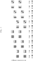
- FIGs. 1 to 4 illustrate patterns of an NR DMRS according to a type and a symbol. Specifically, FIG. 1 illustrates the frequency location of REs occupied by 1-symbol DMRSs in Type 1, FIG. 2 illustrates the frequency location of REs occupied by 2-symbol DMRSs in Type 1, FIG. 3 illustrates the frequency location of REs occupied 1-symbol DMRSs in Type 2, and FIG. 4 illustrates the frequency location of REs occupied by 2-symbol DMRSs in Type 2.
- DMRSs having orthogonality When a plurality of layers occupies the same physical resource block (PRB), the system is required to have DMRSs having orthogonality in order to estimate a channel of each layer.
- a port number may be defined as p -1000.
- four DMRSs having orthogonality may be needed to use four DMRS ports by the BS.
- the BS may secure orthogonality of two DMRSs by allocating different frequency resources to the two DMRSs. Further, the BS may design DMRSs having the same frequency to have orthogonality through a length-2 orthogonal cover code (OCC) having orthogonality in a frequency domain.
- OCC orthogonal cover code
- ports 0 and 1 may use the length-2 OCC in frequencies 0 and 2, frequencies 4 and 6, and frequencies 8 and 10, and ports 2 and 3 may use the length-2 OCC in frequencies 1 and 3, frequencies 5 and 7, and frequencies 9 and 11.
- the BS may further use the length-2 OCC in a time domain in order to provide eight DMRS ports having orthogonality in Type 1.
- ports 0 and 4, ports 1 and 5, ports 2 and 6, and ports 3 and 7 may have orthogonality by the length-2 OCC.
- the BS may secure orthogonality of three DMRSs by allocating different frequency resources to the three DMRSs. Further, the BS may design DMRSs having the same frequency to have orthogonality through a length-2 orthogonal cover code (OCC) having orthogonality in a frequency domain.
- OCC orthogonal cover code
- ports 0 and 1 may use the length-2 OCC in frequencies 0 and 1 and frequencies 6 and 7, ports 2 and 3 may use the length-2 OCC in frequencies 2 and 3 and frequencies 8 and 9, and ports 4 and 5 may use the length-2 OCC in frequencies 4 and 5 and frequencies 10 and 11.
- the BS may further use the length-2 OCC in a time domain in order to provide twelve DMRS ports having orthogonality in Type 2.
- ports 0 and 6, ports 1 and 7, ports 2 and 8, ports 3 and 9, ports 4 and 10, and ports 5 and 11 may have orthogonality by the length-2 OCC in a time domain.
- FIG. 7 illustrates a DMRS port structure in uplink (UL) 2 layer transmission for each user equipment (UE) in multi user-multi input multi output (MU-MIMO).
- UE user equipment
- MU-MIMO multi user-multi input multi output
- a multiuser (MU) MIMO signal is transmitted to the BS, and there is an explicit precoder which the BS knows.
- the BS allocates DMRS 0 and DMRS 1 to UE 0 and DMRS 2 and DMRS 3 to UE 1.
- the BS may use the previously obtained channel estimation value.
- the length of a periodic cyclic prefix may be configured to be longer than the maximum delay length of a multipath which a signal experiences in a radio channel.
- a maximum (max) delay value of a channel defined as an enhanced pedestrian A (EPA) among various channels which an outdoor pedestrian experiences corresponds to 0.41 us.
- a max delay value of a channel defined as an enhanced vehicular A (EVA) among various channels which an outdoor vehicle UE experiences is 2.51 us.
- a max delay value of a channel defined as an enhanced typical urban (ETU) is 5 us.
- the EPA, EVA, and ETU are channels including 7, 9, and 9 multiple paths. That is, max delays of most radio channels may be within the OFDM CP length, and channel taps may be sparsely generated.
- Channels which an actual reception signal experiences may be generated by a combination of a transmission filter of the BS, a sparse radio channel, and a reception filter.
- a transmission filter of the BS a sparse radio channel
- a reception filter a channel which does not vary over the time during 14-symbol 1 slot is assumed.
- the vector y m u is expressed as shown in [Equation 1].
- y m u O 0 O 1 g m , 0 u g m , 1 u + w m u
- CIR channel impulse response
- a plurality of reception antenna ports is co-located, and thus a support of a channel may be maintained regardless of a reception antenna port index.
- each of sparsity of the CIR between transmission layers 0 and 1 and reception antenna port m may be defined as L.
- a matrix F (u ) is a submatrix having the size of 6 ⁇ L including a row vector corresponding to physical RE indexes at which DMRS ports 0 and 1 of PRB u are located and a column vector at channel tap locations of L channel coefficient values in an N ⁇ N Fourier matrix.
- F F u 0 ⁇ F u N PRB ⁇ 1 ⁇ C 6 N PRB ⁇ L
- ⁇ m ⁇ m , 0 T ⁇ m , 1 T T ⁇ C 2 L ⁇ 1
- ⁇ m ⁇ m , 0 T ⁇ m , 1 T T ⁇ C 2 L ⁇ 1
- the precoder matrix, P p 0,0 p 0,1 p 1,0 p 1,1
- ⁇ m, 0 and ⁇ m, 1 which are entries of ⁇ m , that is, the transmit antenna correlation should be considered.
- a covariance matrix may be determined in consideration of a leakage matrix by a transmission/reception filter.
- a submatrix ⁇ ( u ) having the size of 12 ⁇ L including a row vector corresponding to physical RE indexes of REs at which data of PRB u is located and a column vector at channel tap locations at which L channel coefficient values are located may be defined.
- an LMMSE channel estimate of an effective CFR vector f m , n u of reception antenna m on RB u may be expressed as shown below.
- C ⁇ m, 0 and C ⁇ m, 1 are covariance matrixes of effective CIR vector ⁇ m ,0 and ⁇ m, 1 .
- the vector y m u is expressed as shown below.
- y m u O 0 O 1 g m , 0 u g m , 1 u + w m u
- a matrix F ( u ) is a submatrix having the size of 6 ⁇ L including a row vector corresponding to physical RE indexes of REs at which DMRS ports 2 and 3 of PRB u are located and a column vector at channel tap locations of L channel coefficient values in an N ⁇ N Fourier matrix, and F may be defined as shown in [Table 22] below.
- F F u 0 ⁇ F u N PRB ⁇ 1 ⁇ C 6 N PRB ⁇ L
- Type 1 provides a maximum of four DMRS ports.
- Type 2 provides a maximum of six DMRS ports.
- spacing between subcarriers of the DMRS more increases than spacing of Type 1, and thus larger deterioration of channel estimation performance may be expected than Type 1 in a frequency selection channel.
- the above-mentioned channel estimation scheme may be applied after length-2 De-Walsh in a time domain.
- the scheme for estimating the LMMSE channel may have the following problem.
- the scheme for estimating the LMMSE channel may be applied only when sparsity of radio channels and autocorrelation matrixes C ⁇ m and C ⁇ m,n of the radio channels are known.
- the disclosure proposes a channel estimation scheme after DMRSs are allocated to the UE.
- pilot signals uniformly spread to a system band (bandwidth part) viewed from the UE are required.
- the BS may use a sounding reference signal (SRS) in the UL and the UE may use a channel state information-reference signal (CSI-RS) in the DL.
- SRS sounding reference signal
- CSI-RS channel state information-reference signal
- channel sparsity is an amount of a slow change over the time
- the channel sparsity may be approximately obtained as the BS periodically or aperiodically receives the SRS from the UE in the UL and the UE receives the CSI-RS from the BS in the DL.
- the UL a plurality of UEs are required to share and use UL resources for the SRS, and thus UL capacity may decrease due to SRS reception.
- a plurality of UEs may use the same resources for the CSI-RS, and thus a decrease in DL capacity may be relatively smaller than the SRS.
- the BS estimating UL channel sparsity and channel power through the SRS may receive assistance from the DMRS for one scheduled PRB to estimate the channel in the UL
- the UE estimating DL channel sparsity and channel power through the CSI-RS may receive assistance from the DMRS to estimate the channel for the scheduled PRB in the DL.
- the disclosure proposes a channel estimator close to performance of the LMMSE channel estimator which cannot be implemented in fact through the above scheme.
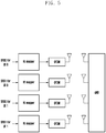
- FIG. 5 illustrates an antenna port structure for an SRS in UL 2 layer transmission for each UE in MU-MIMO
- FIG. 6 illustrates an antenna port structure for a CSI-RS in DL 2 layer transmission for each UE in MU-MIMO.
- SRSs of UE 0 may be mapped to REs through an RE mapper and may be transmitted to the BS through two antenna ports allocated to UE 0.
- SRSs of UE 1 may be transmitted to the BS through two antenna ports.
- CSI-RSs of UE 0 may be mapped to REs through an RE mapper and may be transmitted to UE 0 by the BS through two antenna ports allocated to UE 0.
- CSI-RSs of UE 1 may be transmitted to UE 1 by the BS through two antenna ports.
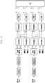
- FIG. 7 illustrates a DMRS port structure in UL 2 layer transmission for each UE in UL MU-MIMO
- FIG. 8 illustrates a DMRS port structure in DL 2 layer transmission for each UE in DL MU-MIMO.
- DMRSs 0 and 1 are allocated to UE 0 and DMRSs 2 and 3 are allocated to UE 1.
- the DMRSs allocated to the UEs may be precoded and mapped to REs through an RE mapper.
- DMRSs 0 and 1 may be transmitted to the BS through DMRS ports 0 and 1 allocated to UE 0.
- DMRSs 2 and 3 may be transmitted to the BS through DMRS ports 2 and 3 allocated to UE 1.
- the BS allocates DMRSs 0 and 1 to UE 0 and DMRSs 2 and 3 to UE 1.
- the DMRSs allocated to the UEs may be precoded and mapped to REs through an RE mapper in the downlink, DMRSs 0 and 1 may be transmitted to UE 0 through DMRS ports 0 and 1 allocated to UE 0.
- DMRSs 2 and 3 may be transmitted to UE 1 through DMRS ports 2 and 3 allocated to UE 1.
- the BS estimates the channel by receiving SRSs transmitted from UE 0 and UE 1 in the UL. At this time, the SRSs may be FDM-transmitted and CDM-transmitted in a system bandwidth (bandwidth part) viewed from the UE and may be distinguished between UEs.
- the UE may estimate the channel by receiving the CSI-RS transmitted from the BS in the DL. At this time, the CSI-RS may be FDM-transmitted and CDM-transmitted in a system bandwidth (bandwidth part) viewed from the UE and may be distinguished between UEs.
- the BS when the BS lets UEs transmit a PUSCH through a PDCCH, a plurality of UEs may transmit the PUSCH on PRBs.
- the BS may allocate different DMRS ports to UE 0 and UE 1, and each DMRS signal passes through a precoder which is the same as a layer of the PUSCH corresponding thereto, and the thus effective CFRs of the DMRSs may be the same.
- a plurality of UEs may receive the PDSCH on PRBs.
- the BS may allocate different DMRS ports to UE 0 and UE 1, and each DMRS signal passes through a precoder which is the same as a layer of the PUSCH corresponding thereto, and the thus effective CFRs of the DMRSs may be the same.
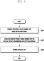
- FIG. 9 is a flowchart illustrating a method of estimating a channel according to an embodiment of the disclosure.
- the BS may estimate an uplink channel by receiving a reference signal from the UE, and the UE may estimate a downlink channel by receiving a reference signal from the BS.
- a method of estimating the uplink channel and a method of estimating the downlink channel may have different entities and different reference signals for channel estimation but the method of estimating channels may correspond to each other.
- the method of estimating the uplink channel by the BS is first described and then the method of estimating the downlink channel by the UE is described.
- the BS may identify locations of at least one radio channel taps on the basis of sounding reference signal (SRS) received from the UE.
- the UE may identify locations of at least one radio channel taps on the basis of a channel state information reference signal (CSI-RS) received from the BS.
- SRS sounding reference signal
- CSI-RS channel state information reference signal
- the location of the radio channel tap may indicate a delay level of a signal received in the channel, the number of delays generated through a multipath channel is called sparsity, and a plurality of delay values are supports.
- the delay of signals may be discontinuous, and there may be a plurality of taps according to the signal delay. Further, the radio channel taps may be sparsely located.
- the BS or the UE may estimate the support on the basis of the received reference signal.
- the BS may determine an average power value of the radio channel taps for each link between a transmission antenna in which the SRS is transmitted and a reception antenna.
- the UE may determine an average channel tap power value for each link between a transmission antenna and a reception antenna in which the CSI-RS is transmitted.
- the average channel tap power may be determined on the assumption that the average channel tap power is uniformly allocated to each link between transmission and reception antennas.
- the BS may estimate an effective channel frequency response (CFR) of a physical uplink shared channel (PUSCH) on the basis of the locations of the radio channel taps and the average power value of the radio channel taps.
- the UE may estimate an effective channel frequency response (CFR) of a physical downlink shared channel (PDSCH) on the basis of the locations of the radio channel taps and the average power value of the radio channel taps.
- CFR effective channel frequency response
- PDSCH physical downlink shared channel
- the method of estimating the uplink channel and the method of estimating the downlink channel may have different entities for estimating channels and received reference signals, but the methods of estimating the channels may correspond to each other.
- the following description will be made on the basis of the assumption of the method of estimating the uplink channel by the BS.
- the method of estimating the uplink channel described with reference to FIGs. 10 , 11 , and 12 below may be applied to the method of estimating the downlink channel by the UE.
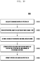
- FIG. 10 is a flowchart illustrating a method of estimating an effective CFR according to an embodiment of the disclosure.
- the BS may determine a covariance matrix of an effective channel impulse response (CIR).
- CIR channel impulse response
- the BS may determine the covariance matrix of the CIR on the basis of the assumption that channel power between a plurality of transmission antennas and reception antennas is uniformly allocated to each channel tap on the basis of the average power value of the radio channel taps in step S920 of FIG. 9 .
- the BS may determine the covariance matrix of the effective CIR using a precoder.
- the BS may determine a system matrix on the basis of the locations of the radio channel taps.
- the locations of the radio channel taps may be estimated in step S910 of FIG. 9 , and the effective CFR may be expressed as a product of the system matrix and the effective CIR.
- the BS may estimate a variance of interference and noise on the basis of a demodulation reference signal (DMRS) received from the UE.
- DMRS demodulation reference signal
- the BS may estimate the effective CIR on the basis of the covariance matrix of the effective CIR, the system matrix, and the variance of interference and noise.
- the BS may estimate the effective CFR on the basis of the effective CIR.
- the BS may perform fast Fourier transform (FFT) on the effective CIR in a frequency domain and estimate the effective CFR of resource elements carrying the PUSCH.
- FFT fast Fourier transform
- the UE may first OCC-decover the DMRS with an orthogonal cover code (OCC) which is code division-multiplexed in a frequency direction (F-CDM) and estimate the channel for each link between one transmission layer and one reception antenna.
- OCC orthogonal cover code
- F-CDM frequency direction
- the BS may jointly estimate the channel for links between a plurality of transmission layers and reception antennas rather than separately estimating the channel for each link between one transmission layer and one reception antenna.
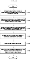
- FIG. 11 is a flowchart illustrating a method of estimating a channel for each link between a transmission layer and a reception antenna according to an embodiment of the disclosure.
- the embodiment describes a method by which the BS first OCC-decovers the DMRS with the OCC and estimates a channel for each antenna link. Further, each step of FIG. 11 is not necessary, and some steps may be omitted.
- the BS may estimate channel power between transmission and reception antennas and determine a covariance matrix of a CIR by dividing the channel power by the number of channel taps.
- the BS may consider that the channel power is uniformly allocated to each channel tap. Since two antenna ports are allocated to the UE, it may be assumed that the BS may receive SRSs transmitted from antenna 0 and antenna 1 of the UE.
- the BS may estimate channel power between transmission and reception antennas from the SRS transmitted from antenna 0 and calculate power obtained by dividing the channel power by the number of channel taps.
- the BS may determine a covariance matrix of a CIR having the power as an entry of a diagonal matrix (diagonal entry).
- the BS may determine a covariance matrix of a CIR from the SRS transmitted from antenna 1 in the same way.
- the BS may calculate a covariance matrix having the covariance matrix of the CIR of antenna 0 and antenna 1 as a diagonal block and determine the covariance matrix of the CIR of antenna 0 and antenna 1.
- the BS may divide a sum of power of two channels estimated from antenna 0 and antenna 1 by the number of taps of the two channels and determine the covariance matrix of the CIR of antenna 0 and antenna 1 having the power as an entry of the diagonal matrix (diagonal entry).
- the BS may consider a reception vector obtained by Walsh-decovering a plurality of reception signals adjacent to the DMRS as a sum of an effective CFR between transmission and reception antennas and noise.
- the BS may Walsh-decover two adjacent reception signals among reception signals of resource elements at which the DMRS, which is frequency-code division-multiplexed (F-FDM), is located.
- F-FDM frequency-code division-multiplexed
- the BS may obtain 2 reception vectors having the size of 3 ⁇ 1.
- the BS may consider each of the vectors as a sum of an effective CFR between transmission layer 0 and a reception antenna and noise and a sum of an effective CFR between transmission layer 1 and a reception antenna and noise. A detailed operation is described below.
- the signal OCC-decovered by the BS may be expressed as described below.
- a reception vector may be expressed as shown below.
- the BS may determine a system matrix obtained by stacking a matrix picking only columns corresponding to the locations of the radio channel taps in a Fourier matrix by the number of observed PRBs.
- the locations of the radio channel taps are estimated from the SRS by the BS, and the BS may determine the system matrix by stacking columns determined on the basis of the locations of the radio channel taps. A detailed operation is described below.
- a system matrix F ' ( u ) may be a submatrix having the size of 3 ⁇ L including a row vector corresponding to physical RE indexes of RE ⁇ 1, 5, 9 ⁇ of PRB u and a column vector at channel tap locations of L channel coefficient values in an N ⁇ N Fourier matrix.
- the effective CFR g m , n u k may be expressed as a product of the system matrix and the effective CIR ⁇ m,n ( l ) below.
- g m , n u F ′ u ⁇ m , n
- the BS may determine a covariance matrix of an effective CIR obtained by combining the covariance matrix of the CIR and the precoder.
- the BS may know the precoder at the receiver. A detailed operation is described below.
- Equation 11 may be expressed as [Equation 35] below.
- C ⁇ m P T ⁇ I L
- C ⁇ m P ⁇ ⁇ I L
- C ⁇ m is a covariance matrix of ⁇ m , and may be determined as shown below on the basis of the assumption that channel power is estimated from the SRS and a variance of a channel coefficient located at each tap is the same.
- C ⁇ m ⁇ ⁇ m , 0 2 I L ⁇ ⁇ m , 1 2 I L
- ⁇ ⁇ m , n 2 may be power of a predetermined channel tap coefficient between Tx antenna n' and Rx antenna m.
- the BS may estimate a noise variance of an observed PRB.
- the BS may estimate an effective CIR on the assumption that the effective CFR is the product of the system matrix and the effective CIR and estimate the effective CFR in a frequency domain.
- the BS may estimate the effective CIR and the effective CFR through a regularized maximum likelihood (ML) scheme. Further, the BS may determine a first submatrix having the size of L ⁇ L located on a diagonal line in the covariance matrix of the effective CIR as an effective CIR matrix between transmission layer 0 and a reception antenna, and determine a second submatrix having the size of L ⁇ L located on a diagonal line in the covariance matrix of the effective CIR as an effective CIR matrix between transmission layer 1 and a reception antenna.
- ML maximum likelihood
- ⁇ ( u ) is a data tone Fourier matrix and may transform data from a time domain to a frequency domain.
- FIG. 12 is a flowchart illustrating a method of jointly estimating a channel for a link between a transmission layer and a reception antenna according to an embodiment of the disclosure.
- the embodiment relates to a method by which the BS jointly estimates a channel for links between a plurality of transmission layers and reception antennas rather than separately estimating a channel for each link between one transmission layer and one reception antenna. Further, each step of FIG. 12 is not necessary, and some steps may be omitted.
- the BS may estimate channel power between transmission and reception antennas and determine a covariance matrix of a CIR by dividing the channel power by the number of channel taps.
- a method by which the BS determines the covariance of the CIR may correspond to step S1110 of FIG. 11 .
- the BS may consider a vector received in an RE of the DMRS as a sum of an effective CFR between transmission and reception antennas and noise.
- the BS may obtain 1 reception vector having the size of 6 ⁇ 1.
- the BS may consider the vector as a sum of an effective CFR between transmission layer 0 and a reception antenna, an effective CFR between transmission layer 1 and a reception antenna, and noise.
- the BS may stack a matrix obtained by picking only columns corresponding to the locations of the radio channel taps from a Fourier matrix by the number of observed PRBs and determine a system matrix using a Walsh code. Since the case of the 1-symbol DMRS pattern and Type 1 and the case in which channels are jointly estimated for links between a plurality of transmission and repletion antennas are assumed, the BS may determine the system matrix by applying Walsh code 0 and Walsh code 1.
- the BS may determine the stacked covariance matrix of the effective CIR obtained by combining the covariance matrix of the CIR and the precoder.
- a method by which the BS determines the stacked covariance matrix of the effective CIR may correspond to step S1140 of FIG. 11 .
- the BS may estimate a noise variance of an observed PRB.
- the BS may estimate an effective CIR on the assumption that the effective CFR is the product of the system matrix and the effective CIR and estimate the effective CFR in a frequency domain.
- the BS may estimate the effective CIR and the effective CFR through a regularized maximum likelihood (ML) scheme. A detailed operation is described below.
- ⁇ ⁇ m ⁇ H ⁇ + ⁇ w 2 C ⁇ m ⁇ 1 ⁇ 1 ⁇ H y m
- the BS may estimate the effective CFR through a method similar to that in FIG. 12 also in the case in which DMRS transmission antenna port 4 or DMRS transmission antenna port 5 is allocated to the UE.
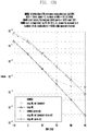
- FIGs. 13A and 13B illustrate performance of an effective CFR estimation value in an EPA channel
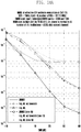
- FIGs. 14A and 14B illustrate performance of an effective CFR estimation value in an ETU channel
- FIGs. 13A , 13B , 14A , and 14B show normalized mean square error (NMSE) performance of an effective CFR estimation value in various channel estimation schemes.
- NMSE normalized mean square error
- a channel is static, and a delay and a power profile are EPA channels of [0 30 70 90 110 190 410] ⁇ ns and [0.3213 0.2552 0.2027 0.1610 0.0509 0.0061 0.0027], respectively.
- the multipath of the channels is independent and follows zero-mean normal distribution.
- a channel implemented to follow the distribution may be scaled to have total power of 4.
- a channel is static, and a delay and a power profile are ETU channels of [0 50 120 200 230 500 1600 2300 5000] ⁇ ns and [0.1241 0.1241 0.1241 0.1563 0.1563 0.1563 0.0783 0.0494 0.0312], respectively.
- the multipath of the channels is independent and follows zero-mean normal distribution.
- a channel implemented to follow the distribution may be scaled to have total power of 4.
- FIG. 13A illustrates the case of DMRS configuration type 1 in which a channel is an EPA
- FIG. 13B illustrates the case of DMRS configuration type 2 in which a channel is an EPA
- FIG. 14A illustrates the case of DMRS configuration type 1 in which a channel is an ETU
- FIG. 14B illustrates the case of DMRS configuration type 2 in which a channel is an ETU.
- an LMMSE channel estimation scheme shows the best performance.
- FIG. 13A it may be noted that in the case in which 52 PRBs are allocated in an EPA channel 10 ⁇ -2 NMSE has a more excellent performance of 11.2 dB than the case in which 1 PRB is allocated.
- channel estimation is performed for one transmission layer and for each antenna link, it may be noted that an error floor appears near 30 dB.
- an LMMSE channel estimation scheme shows the best performance.
- FIG. 14A it may be noted that in the case in which 52 PRBs are allocated in an ETU channel 10 ⁇ -2 NMSE has a more excellent performance of 13.3 dB than the case in which 1 PRB is allocated.
- channel estimation is performed for each link between one transmission layer and one reception antenna, it may be noted that an error floor appears near 10 dB.
- a high-performance channel estimator is needed when 64 QAM and high rate data close to code rate 1 are used in the UL in a channel such as an ETU channel having heavy frequency selection and the DMRS is F-code division-multiplexed (CDM) for MIMO (of a strong electric field having an SNR higher than or equal to 10 dB), and it may be noted that the disclosure has a very excellent channel estimation performance in such an environment.
- CDM F-code division-multiplexed
- FIG. 15 is a block diagram illustrating an internal structure of a BS according to an embodiment of the disclosure.
- the BS according to the disclosure may include a transceiver 1510 and a controller 1520.
- the transceiver 1510 of the BS may transmit and receive messages between the BS and a UE.
- the transceiver 1510 may include a wired or wireless interface.
- the transceiver 1510 may receive an SRS from the UE.
- the controller 1520 of the BS may control the overall operation of the BS.
- the controller 1520 may estimate the location of a radio channel tap on the basis of the SRS received from the UE, determine an average power value of the radio channel tap for each link between a transmission antenna in which the SRS is transmitted and a reception antenna, and estimate an effective CFR of a PUSCH on the basis of the location of the radio channel tap and the average power value of the radio channel tap.
- the operation of the controller 1520 may correspond to FIG. 9 .
- the controller 1520 may determine a covariance matrix of the effective CIR on the basis of the assumption that channel power between the transmission antenna and the reception antenna is uniformly allocated to each channel tap, determine a system matrix on the basis of the location of the radio channel tap, estimate a variance of interference and noise on the basis of the DMRS received from the UE, estimate the effective CIR on the basis of the covariance matrix of the effective CIR, the system matrix, and the variance of the interference and noise, perform FFT on the effective CIR in a frequency domain, and estimate the effective CFR of a resource element carrying a PUSCH.
- the operation of the controller 1520 may correspond to FIG. 10 .
- the controller 1520 may stack a matrix picking only a column corresponding to the location of the radio channel tap acquired from the SRS in a Fourier matrix by the number of observed PRBs, determine the system matrix, and estimate the effective CIR on the basis of signals obtained by performing Walsh decovering on a plurality of adjacent reception signals among reception signals of resource elements at which F-CDM DMRSs are located.
- the operation of the controller 1520 may correspond to FIG. 11 .
- the controller 1520 may stack a matrix picking only a column corresponding to the location of the radio channel tap acquired from the SRS in a Fourier matrix by the number of observed PRBs, determine the system matrix using a Walsh code, and estimate the effective CIR on the basis of a reception signal of a resource element at which the DMRS acquired for each PRB is located according to the number and type of symbols of the F-CDM DMRS.
- the operation of the controller 1520 may correspond to FIG. 12 .
- the controller 1520 may determine a covariance matrix of a CIR with diagonal entries by estimating channel power on each of a plurality of transmission and reception antennas and dividing the channel power by the number of channel taps or dividing a sum of the channel power on the plurality of transmission and reception antennas by a sum of the numbers of channel taps.
- the operation of the controller 1520 may correspond to step S1110 of FIG. 11 and step S1210 of FIG. 12 .
- FIG. 16 is a block diagram illustrating an internal structure of a UE according to an embodiment of the disclosure. As illustrated in FIG. 16 , the UE according to the disclosure may include a transceiver 1610 and a controller 1620.
- the transceiver 1610 of the UE may transmit and receive messages between the BS and the UE.
- the transceiver 1610 may include a wired or wireless interface.
- the transceiver 1610 may receive a CSI-RS from the BS.
- the controller 1620 of the UE may control the overall operation of the UE.
- the controller 1620 may estimate the location of a radio channel tap on the basis of the CSI-RS received from the BS, determine an average power value of the radio channel tap for each link between a transmission antenna in which the SRS is transmitted and a reception antenna, and estimate an effective CFR of a PDSCH on the basis of the location of the radio channel tap and the average power value of the radio channel tap.
- the operation of the controller 1620 may correspond to the operation of the BS of FIG. 15 with only difference in entities performing the operation and received reference signals.
- the controller 1620 may determine a covariance matrix of the effective CIR on the basis of the assumption that channel power between the transmission antenna and the reception antenna is uniformly allocated to each channel tap, determine a system matrix on the basis of the location of the radio channel tap, estimate a variance of interference and noise on the basis of the DMRS received from the BS, estimate the effective CIR on the basis of the covariance matrix of the effective CIR, the system matrix, and the variance of the interference and noise, transform FFT on the effective CIR in a frequency domain, and estimate an effective CFR of a resource element carrying a PDSCH.
- the controller 1620 may stack a matrix picking only a column corresponding to the location of the radio channel tap acquired from the CSI-RS in a Fourier matrix by the number of observed PRBs, determine the system matrix, and estimate the effective CIR on the basis of signals obtained by performing Walsh decovering on a plurality of adjacent reception signals among reception signals of resource elements at which F-CDM DMRSs are located.
- the controller 1620 may stack a matrix picking only a column corresponding to the location of the radio channel tap acquired from the CSI-RS in a Fourier matrix by the number of observed PRBs, determine the system matrix using a Walsh code, and estimate the effective CIR on the basis of a reception signal of a resource element at which the DMRS acquired for each PRB is located according to the number and type of symbols of the F-CDM DMRS.
- the controller 1620 may determine a covariance matrix of a CIR with diagonal entries by estimating channel power on each of a plurality of transmission and reception antennas and dividing the channel power by the number of channel taps or dividing a sum of the channel power on the plurality of transmission and reception antennas by a sum of channel taps.
Landscapes
- Engineering & Computer Science (AREA)
- Signal Processing (AREA)
- Computer Networks & Wireless Communication (AREA)
- Power Engineering (AREA)
- Physics & Mathematics (AREA)
- Mathematical Physics (AREA)
- Mobile Radio Communication Systems (AREA)
- Radio Transmission System (AREA)
Abstract
Description
- The disclosure relates to a wireless communication system and, more particularly, to a method and an apparatus for estimating a channel using a demodulation reference signal (DMRS) in a wireless communication system.
- In general, a mobile communication system is developed to provide voice services while guaranteeing activity of users. However, the mobile communication system has gradually expanded its service area up to a data service as well as a voice service and has been developed to provide a high speed data service at present. However, since resources are lacking and users demand higher speed services in the mobile communication system providing a current service, a further improved mobile communication system is needed.
- To meet the demands, standardization of long term evolution (LTE) is being conducted by the 3rd generation partnership project (3GPP) as one of the next generation mobile communication systems that are being developed. LTE is a technology implementing high speed packet-based communication having a transmission rate of a maximum of 100 Mbps with the goal being to commercialize LTE in 2010. To this end, several methods are being discussed, including a method of reducing the number of nodes located on a communication channel by simplifying network architecture or a method of making wireless protocols the closest to a wireless channel.
- To meet the demand for wireless data traffic having increased since deployment of 4G communication systems, efforts have been made to develop an improved 5G or pre-5G communication system. Therefore, the 5G or pre-5G communication system is also called a "Beyond 4G Network" or a "Post LTE System". The 5G communication system is considered to be implemented in higher frequency (mmWave) bands, e.g., 60GHz bands, so as to accomplish higher data rates. To decrease propagation loss of the radio waves and increase the transmission distance, the beamforming, massive multiple-input multiple-output (MIMO), full dimensional MIMO (FD-MIMO), array antenna, an analog beam forming, large scale antenna techniques are discussed in 5G communication systems. In addition, in 5G communication systems, development for system network improvement is under way based on advanced small cells, cloud radio access networks (RANs), ultra-dense networks, device-to-device (D2D) communication, wireless backhaul, moving network, cooperative communication, coordinated multi-points (CoMP), reception-end interference cancellation and the like. In the 5G system, hybrid FSK and QAM modulation (FQAM) and sliding window superposition coding (SWSC) as an advanced coding modulation (ACM), and filter bank multi carrier (FBMC), non-orthogonal multiple access(NOMA), and sparse code multiple access (SCMA) as an advanced access technology have also been developed.
- The Internet, which is a human centered connectivity network where humans generate and consume information, is now evolving to the Internet of things (IoT) where distributed entities, such as things, exchange and process information without human intervention. The Internet of everything (IoE), which is a combination of the IoT technology and the big data processing technology through connection with a cloud server, has emerged. As technology elements, such as "sensing technology", "wired/wireless communication and network infrastructure", "service interface technology", and "security technology" have been demanded for IoT implementation, a sensor network, a machine-to-machine (M2M) communication, machine type communication (MTC), and so forth have been recently researched. Such an IoT environment may provide intelligent Internet technology services that create a new value to human life by collecting and analyzing data generated among connected things. IoT may be applied to a variety of fields including smart home, smart building, smart city, smart car or connected cars, smart grid, health care, smart appliances and advanced medical services through convergence and combination between existing information technology (IT) and various industrial applications.
- In line with this, various attempts have been made to apply 5G communication systems to IoT networks. For example, technologies such as a sensor network, machine type communication (MTC), and machine-to-machine (M2M) communication may be implemented by beamforming, MIMO, and array antennas. Application of a cloud radio access network (RAN) as the above-described big data processing technology may also be considered an example of convergence of the 5G technology with the IoT technology.
- Meanwhile, clusters including a plurality of scatterers or reflectors exist in a wireless channel, and as a result, a receiver receives transmission signals through multiple paths. Since a new radio (NR) DL/UL OFDM symbol has a CP before a net OFDM and thus discards the CP and, when samples corresponding to the size of fast Fourier transform (FFT) are obtained, inter symbol interference (ISI) does not occur. In NR, 14 symbol slots or 12 symbol slots are defined, and a plurality of physical resource blocks (PRBs) exists during 1 slot interval. When a type of a CP is a normal CP, 1 PRB includes 14 OFDM symbols in a time domain and 12 resource elements (REs) in a frequency domain. Accordingly, 1 PRB has 168 REs. When a type of a CP is an extended CP, 1 PRB includes 12 OFDM symbols in a time domain and 12 resource elements (REs) in a frequency domain. Accordingly, 1 PRB has 144 REs. In order to perform coherent demodulation, the BS may have a plurality of transmission antenna ports, and respective antenna ports are disjointly associated with different DMRSs. The NR standard supports 4 DMRS ports in
Type Type 2 based on a 1-symbol DMRS. The NR standard supports 8 DMRS ports inType 1 and 12 DMRS ports inType 2 based on a 2-symbol DMRS. If FFT is performed on N FFT samples in a time domain in which the CP is discarded and taken, a reception in a specific RE to which a DMRS is allocated in a frequency domain may be obtained. As the number of antennas of the BS increases for efficient MIMO transmission, an increase in the number of pilots having the correlation with antenna ports has become a big issue. - An aspect of the disclosure is to provide a method and an apparatus for estimating a channel to receive a multi-input multi-output (MIMO) signal.
- In accordance with an aspect of the disclosure, a method of estimating an uplink channel by a BS in a wireless communication system includes: identifying locations of at least one radio channel taps, based on a sounding reference signal (SRS) received from a UE; determining an average power value of the radio channel taps for each link between a transmission antenna in which the SRS is transmitted and a reception antenna; and estimating an effective channel frequency response (CFR) of a physical uplink shared channel (PUSCH), based on the locations of the radio channel taps and the average power value of the radio channel taps.
- In accordance with another aspect of the disclosure, a method of estimating a downlink channel by a UE in a wireless communication system includes: identifying locations of at least one radio channel tap, based on a channel state information reference signal (CSI-RS) received from a BS; determining an average power value of the radio channel taps for each link between a transmission antenna in which the CSI-RS is transmitted and a reception antenna; and estimating an effective channel frequency response (CFR) of a physical downlink shared channel (PDSCH), based on the locations of the radio channel taps and the average power value of the radio channel taps.
- In accordance with another aspect of the disclosure, a BS for estimating an uplink channel in a wireless communication system includes: a transceiver configured to transmit and receive a signal; and a controller configured to identify locations of at least one radio channel tap, based on a sounding reference signal (SRS) received from a UE, determine an average power value of the radio channel taps for each link between a transmission antenna in which the SRS is transmitted and a reception antenna, and estimate an effective channel frequency response (CFR) of a physical uplink shared channel (PUSCH), based on the locations of the radio channel taps and the average power value of the radio channel taps.
- In accordance with another aspect of the disclosure, a UE for estimating a downlink channel in a wireless communication system includes: a transceiver configured to transmit and receive a signal; and a controller configured to identify locations of at least one radio channel tap, based on a channel state information reference signal (CSI-RS) received from a BS, determine an average power value of the radio channel taps for each link between a transmission antenna in which the CSI-RS is transmitted and a reception antenna, and estimate an effective channel frequency response (CFR) of a physical downlink shared channel (PDSCH), based on the locations of the radio channel taps and the average power value of the radio channel taps.
- The disclosure can improve channel estimation performance for receiving a new radio (NR) multi-input multi-output (MIMO) signal. Further, the disclosure can obtain performance of estimating a channel close to an LMMSE channel estimator, which cannot be implemented in fact, using a support of a channel obtained through a channel state information reference signal (CSI-RS) or a sounding reference signal (SRS) and a pattern of code division-multiplexed (CDM) DMRS.
-
-
FIG. 1 illustrates frequency locations of REs occupied by 1-symbol DMRSs inType 1; -
FIG. 2 illustrates frequency locations of REs occupied by 2-symbol DMRSs inType 1; -
FIG. 3 illustrates frequency locations of REs occupied by 1-symbol DMRSs inType 2; -
FIG. 4 illustrates frequency locations of REs occupied by 2-symbol DMRSs inType 2; -
FIG. 5 illustrates an antenna port structure inUL 2 layer transmission for each UE in MU-MIMO; -
FIG. 6 illustrates an antenna port structure inDL 2 layer transmission for each UE in MU-MIMO; -
FIG. 7 illustrates a DMRS port structure inUL 2 layer transmission for each UE in UL MU-MIMO; -
FIG. 8 illustrates a DMRS port structure inDL 2 layer transmission for each UE in DL MU-MIMO; -
FIG. 9 is a flowchart illustrating a method of estimating a channel according to an embodiment of the disclosure; -
FIG. 10 is a flowchart illustrating a method of estimating an effective CFR according to an embodiment of the disclosure; -
FIG. 11 is a flowchart illustrating a method of estimating a channel for each link between a transmission layer and a reception antenna according to an embodiment of the disclosure; -
FIG. 12 is a flowchart illustrating a method of jointly estimating channels for a link between a transmission layer and a reception antenna according to embodiments of the disclosure; -
FIGs. 13A and13B illustrate performance of an estimate of an effective CFR under an EPA channel; -
FIGs. 14A and14B illustrate performance of an estimate of an effective CFR under an ETU channel; -
FIG. 15 is a block diagram illustrating an internal structure of a BS according to an embodiment of the disclosure; and -
FIG. 16 is a block diagram illustrating an internal structure of a UE according to an embodiment of the disclosure. - In describing embodiments of the disclosure, descriptions related to technical contents well-known in the art and not associated directly with the disclosure will be omitted. Such an omission of unnecessary descriptions is intended to prevent obscuring of the main idea of the disclosure and more clearly transfer the main idea.
- For the same reason, in the accompanying drawings, some elements may be exaggerated, omitted, or schematically illustrated. Further, the size of each element does not completely reflect the actual size. In the drawings, identical or corresponding elements are provided with identical reference numerals.
- The advantages and features of the disclosure and ways to achieve them will be apparent by making reference to embodiments as described below in detail in conjunction with the accompanying drawings. However, the disclosure is not limited to the embodiments set forth below, but may be implemented in various different forms. The following embodiments are provided only to completely disclose the disclosure and inform those skilled in the art of the scope of the disclosure, and the disclosure is defined only by the scope of the appended claims. Throughout the specification, the same or like reference numerals designate the same or like elements.
- Here, it will be understood that each block of the flowchart illustrations, and combinations of blocks in the flowchart illustrations, can be implemented by computer program instructions. These computer program instructions can be provided to a processor of a general purpose computer, special purpose computer, or other programmable data processing apparatus to produce a machine, such that the instructions, which execute via the processor of the computer or other programmable data processing apparatus, create means for implementing the functions specified in the flowchart block or blocks. These computer program instructions may also be stored in a computer usable or computer-readable memory that can direct a computer or other programmable data processing apparatus to function in a particular manner, such that the instructions stored in the computer usable or computer-readable memory produce an article of manufacture including instruction means that implement the function specified in the flowchart block or blocks. The computer program instructions may also be loaded onto a computer or other programmable data processing apparatus to cause a series of operational steps to be performed on the computer or other programmable apparatus to produce a computer implemented process such that the instructions that execute on the computer or other programmable apparatus provide steps for implementing the functions specified in the flowchart block or blocks.
- Further, each block of the flowchart illustrations may represent a module, segment, or portion of code, which includes one or more executable instructions for implementing the specified logical function(s). It should also be noted that in some alternative implementations, the functions noted in the blocks may occur out of the order. For example, two blocks shown in succession may in fact be executed substantially concurrently or the blocks may sometimes be executed in the reverse order, depending upon the functionality involved.
- As used herein, the "unit" refers to a software element or a hardware element, such as a Field Programmable Gate Array (FPGA) or an Application Specific Integrated Circuit (ASIC), which performs a predetermined function. However, the "unit" does not always have a meaning limited to software or hardware. The "unit" may be constructed either to be stored in an addressable storage medium or to execute one or more processors. Therefore, the "unit" includes, for example, software elements, object-oriented software elements, class elements or task elements, processes, functions, properties, procedures, sub-routines, segments of a program code, drivers, firmware, micro-codes, circuits, data, database, data structures, tables, arrays, and parameters. The elements and functions provided by the "unit" may be either combined into a smaller number of elements, or a "unit", or divided into a larger number of elements, or a "unit". Moreover, the elements and "units" or may be implemented to reproduce one or more CPUs within a device or a security multimedia card.
- Hereinafter, a method of estimating a reception channel using a DMRS for NR MIMO reception by a UE and a BS in a wireless communication system will be described. In the case of a downlink, the UE may use a location of a radio channel tap estimated using a channel state information-reference signal (CSI-RS). The location of the radio channel tap may indicate a delay level of a signal received in the channel, the number of delays generated through a multipath channel is called sparsity, and a plurality of delay values are supports. The delay of signals may be discontinuous, and there may be a plurality of taps according to the signal delay. Further, the radio channel taps may be sparsely located. In the case of an uplink, the BS may use supports of a channel estimated on the basis of a sounding reference signal (SRS).
- When a cyclic prefix-orthogonal frequency division multiplexing (CP-OFDM) is used in NR, the same demodulation reference signal (DMRS) pattern may be used for both a physical downlink shared channel (PDSCH) and a physical uplink shared channel (PUSCH). Particularly, the DMRS may be transmitted in a code division multiplexing (CDM) scheme in time and frequency domains. A DMRS signal corresponding to each layer may be required to estimate a channel for SU-MIMO reception, and the case in which a DMRS code division-multiplexed in the frequency domain is received in a frequency selection channel may need further improved channel estimation algorithm than other cases. The disclosure describes a method of estimating a channel using supports of a channel obtained through a CSI-RS or an SRS and a pattern of a code division-multiplexed DMRS.
- The disclosure relates to a method of estimating a reception channel in a wireless communication system, and the method of estimating the reception channel is not limited to the embodiments but may be implemented in various ways.
-
FIGs. 1 to 4 illustrate patterns of an NR DMRS according to a type and a symbol. Specifically,FIG. 1 illustrates the frequency location of REs occupied by 1-symbol DMRSs inType 1,FIG. 2 illustrates the frequency location of REs occupied by 2-symbol DMRSs inType 1,FIG. 3 illustrates the frequency location of REs occupied 1-symbol DMRSs inType 2, andFIG. 4 illustrates the frequency location of REs occupied by 2-symbol DMRSs inType 2. - When a plurality of layers occupies the same physical resource block (PRB), the system is required to have DMRSs having orthogonality in order to estimate a channel of each layer. For convenience, a port number may be defined as p-1000. In the case of
Type 1, four DMRSs having orthogonality may be needed to use four DMRS ports by the BS. The BS may secure orthogonality of two DMRSs by allocating different frequency resources to the two DMRSs. Further, the BS may design DMRSs having the same frequency to have orthogonality through a length-2 orthogonal cover code (OCC) having orthogonality in a frequency domain. - In
FIG. 1 ,ports frequencies frequencies frequencies ports frequencies frequencies frequencies Type 1. InFIG. 2 ,ports ports ports ports - In the case of
Type 2, six DMRSs having orthogonality may be needed to use six DMRS ports by the BS. The BS may secure orthogonality of three DMRSs by allocating different frequency resources to the three DMRSs. Further, the BS may design DMRSs having the same frequency to have orthogonality through a length-2 orthogonal cover code (OCC) having orthogonality in a frequency domain. - In
FIG. 3 ,ports frequencies frequencies ports frequencies frequencies ports frequencies frequencies Type 2. InFIG. 4 ,ports ports ports ports ports ports -
FIG. 7 illustrates a DMRS port structure in uplink (UL) 2 layer transmission for each user equipment (UE) in multi user-multi input multi output (MU-MIMO). InFIG. 7 , it may be noted that the number of transmission antennas ofUE 0 is 2 and an MIMO signal of two DMRS ports may be transmitted to a BS (gNB). Further, it may be noted that the number of transmission antennas ofUE 1 is 2 and an MIMO signal of two DMRS ports may be transmitted to the BS. - Since a particular PRB is shared between
UE 0 andUE 1, a multiuser (MU) MIMO signal is transmitted to the BS, and there is an explicit precoder which the BS knows. The BS allocatesDMRS 0 andDMRS 1 toUE 0 andDMRS 2 andDMRS 3 toUE 1. When the BS performs matched filtering on symbols carried on two layers forUE 0 and two layers forUE 1 after performing channel estimation using 4 DMRSs, the BS may use the previously obtained channel estimation value. - The length of a periodic cyclic prefix (CP) may be configured to be longer than the maximum delay length of a multipath which a signal experiences in a radio channel. A maximum (max) delay value of a channel defined as an enhanced pedestrian A (EPA) among various channels which an outdoor pedestrian experiences corresponds to 0.41 us. A max delay value of a channel defined as an enhanced vehicular A (EVA) among various channels which an outdoor vehicle UE experiences is 2.51 us. Further, a max delay value of a channel defined as an enhanced typical urban (ETU) is 5 us. The EPA, EVA, and ETU are channels including 7, 9, and 9 multiple paths. That is, max delays of most radio channels may be within the OFDM CP length, and channel taps may be sparsely generated. Channels which an actual reception signal experiences may be generated by a combination of a transmission filter of the BS, a sparse radio channel, and a reception filter. Hereinafter, a channel which does not vary over the time during 14-
symbol 1 slot is assumed. - When a transmitter uses
ports Type 1, the DMRSs onsubcarriers transmission layer 0 and reception antenna port m may be defined as
transmission layer 1 and reception antenna port m may be defined as


- Here,

- The OCC is the same in the same of PRBs, and thus an index u may be omitted. When the effective CFR


- The effective CIR vector γ m,n =[γ m,n (O) γ m,n (1)...γ m,n (L-1)] T is a column vector having only a non-zero entry of an effective channel impulse response (CIR) between transmission layer n and reception antenna port m. A plurality of reception antenna ports is co-located, and thus a support of a channel may be maintained regardless of a reception antenna port index. At this time, each of sparsity of the CIR between
transmission layers DMRS ports - When a reception signal and a noise signal in NPRB RPBs are defined as


- ⊗ is a Kronecker product, IN
PRB is a NPRB × NPRB identity matrix, and F may be defined as [Equation 5] below.
- Since the effective CIR γ m,n (l) is a precoded version of the CIR η m,n'(l), if a coefficient of a precoder for layer n and tx antenna n' is defined as pn',n , the following equation is established.


- [Equation 6] and [Equation 7] are expressed as shown below.

- A CIR vector is η m,n' = [η m'n (0) η m'n (1)... η m,n' (L-1)] T , and a CIR vector and an effective CIR vector stacked for a specific reception antenna with different transmission layer indexes are defined below.


- The following equation may be obtained using [Equation 8], [Equation 9], and [Equation 10].

- The precoder matrix,

- If [Equation 11] is substituted for [Equation 4],

and Φ is defined as shown below.
- LMMSE estimate of the CIR is expressed as shown below.

- In [Equation 15], C η m is a covariance matrix of η m , and [Equation 16] is made using O o that is an identity matrix.

- When C η m is determined, the correlation between η m,0 and η m,1 which are entries of η m , that is, the transmit antenna correlation should be considered. If a channel coefficient is not located at a tap in an accurate sample space, a covariance matrix may be determined in consideration of a leakage matrix by a transmission/reception filter. In an N × N Fourier matrix, a submatrix ψ(u) having the size of 12 × L including a row vector corresponding to physical RE indexes of REs at which data of PRB u is located and a column vector at channel tap locations at which L channel coefficient values are located may be defined. If an effective CFR vector of the RE in transmission layer n on PRB u carrying a shared channel and reception antenna m is defined as


- If only one of DMRS
transmission antenna port 0 and DMRStransmission antenna port 1 is activated, an LMMSE channel estimate of an effective CFR vector


- In [Equation 18] and [Equation 19], C γ
m,0 and C γm,1 are covariance matrixes of effective CIR vector γ m,0 and γ m,1. - When a transmitter uses
ports Type 1, the DMRSs onsubcarriers transmission layer 0 and reception antenna port m may be defined as
transmission layer 1 and reception antenna port m may be defined as


- If the effective CFR


- When the FFT size is N, a matrix F (u) is a submatrix having the size of 6 × L including a row vector corresponding to physical RE indexes of REs at which
DMRS ports 
- Through a development similar to that from [Equation 4] to [Equation 16] above, an LMMSE estimate of an effective CFR vector


- In [Equation 23], a CIR vector estimate η̂ m is as shown below.

- In the case of a 1-symbol DMRS,
Type 1 provides a maximum of four DMRS ports. In the case of a 1-symbol DMRS,Type 2 provides a maximum of six DMRS ports. In order to provide relatively more DMRSs, spacing between subcarriers of the DMRS more increases than spacing ofType 1, and thus larger deterioration of channel estimation performance may be expected thanType 1 in a frequency selection channel. - When a transmitter uses
ports Type 2, the DMRSs onsubcarriers transmission layers - When a transmitter uses
ports Type 2, the DMRSs onsubcarriers transmission layers - When a transmitter uses
ports Type 2, the DMRSs onsubcarriers transmission layers - When the channel estimation is performed using the 2-symbol DMRS illustrated in
FIG. 2 (type 1) andFIG. 4 (type 2), the above-mentioned channel estimation scheme may be applied after length-2 De-Walsh in a time domain. - Meanwhile, the scheme for estimating the LMMSE channel may have the following problem. As noted from [Equation 3], [Equation 15], [Equation 18], [Equation 19], [Equation 21], and [Equation 24], the scheme for estimating the LMMSE channel may be applied only when sparsity of radio channels and autocorrelation matrixes C η m and C γ m,n of the radio channels are known. However, it is impossible for the UE to obtain the accurate statistical value, a sub-optimal channel estimator is needed.
- The disclosure proposes a channel estimation scheme after DMRSs are allocated to the UE. In order to obtain sparsity of DL/UL channels, pilot signals uniformly spread to a system band (bandwidth part) viewed from the UE are required. In order to precisely estimate a channel between the UE and the BS in NR, the BS may use a sounding reference signal (SRS) in the UL and the UE may use a channel state information-reference signal (CSI-RS) in the DL.
- Since channel sparsity is an amount of a slow change over the time, the channel sparsity may be approximately obtained as the BS periodically or aperiodically receives the SRS from the UE in the UL and the UE receives the CSI-RS from the BS in the DL. In the UL, a plurality of UEs are required to share and use UL resources for the SRS, and thus UL capacity may decrease due to SRS reception. In the DL, a plurality of UEs may use the same resources for the CSI-RS, and thus a decrease in DL capacity may be relatively smaller than the SRS.
- The BS estimating UL channel sparsity and channel power through the SRS may receive assistance from the DMRS for one scheduled PRB to estimate the channel in the UL, and the UE estimating DL channel sparsity and channel power through the CSI-RS may receive assistance from the DMRS to estimate the channel for the scheduled PRB in the DL. The disclosure proposes a channel estimator close to performance of the LMMSE channel estimator which cannot be implemented in fact through the above scheme.
-
FIG. 5 illustrates an antenna port structure for an SRS inUL 2 layer transmission for each UE in MU-MIMO, andFIG. 6 illustrates an antenna port structure for a CSI-RS inDL 2 layer transmission for each UE in MU-MIMO. - In
FIG. 5 , SRSs ofUE 0 may be mapped to REs through an RE mapper and may be transmitted to the BS through two antenna ports allocated toUE 0. Similarly, SRSs ofUE 1 may be transmitted to the BS through two antenna ports. - In
FIG. 6 , CSI-RSs ofUE 0 may be mapped to REs through an RE mapper and may be transmitted toUE 0 by the BS through two antenna ports allocated toUE 0. Similarly, CSI-RSs ofUE 1 may be transmitted toUE 1 by the BS through two antenna ports. -
FIG. 7 illustrates a DMRS port structure inUL 2 layer transmission for each UE in UL MU-MIMO, andFIG. 8 illustrates a DMRS port structure inDL 2 layer transmission for each UE in DL MU-MIMO. - In
FIG. 7 , it may be assumed thatDMRSs UE 0 and DMRSs 2 and 3 are allocated toUE 1. The DMRSs allocated to the UEs may be precoded and mapped to REs through an RE mapper. DMRSs 0 and 1 may be transmitted to the BS throughDMRS ports UE 0. DMRSs 2 and 3 may be transmitted to the BS throughDMRS ports UE 1. - In
FIG. 8 , it may be assumed that the BS allocatesDMRSs UE 0 and DMRSs 2 and 3 toUE 1. Like inFIG. 7 , the DMRSs allocated to the UEs may be precoded and mapped to REs through an RE mapper in the downlink,DMRSs UE 0 throughDMRS ports UE 0. DMRSs 2 and 3 may be transmitted toUE 1 throughDMRS ports UE 1. - In the disclosure, it may be assumed that sparsity of the channel and power of the channel are estimated from the SRS which the UE transmits to the BS in the UL as shown in
FIG. 5 and from the CSI-RS which the BS transmits to the UE in the DL as shown inFIG. 6 in order to estimate the effective CFR. InFIG. 5 , the BS estimates the channel by receiving SRSs transmitted fromUE 0 andUE 1 in the UL. At this time, the SRSs may be FDM-transmitted and CDM-transmitted in a system bandwidth (bandwidth part) viewed from the UE and may be distinguished between UEs. InFIG. 6 , the UE may estimate the channel by receiving the CSI-RS transmitted from the BS in the DL. At this time, the CSI-RS may be FDM-transmitted and CDM-transmitted in a system bandwidth (bandwidth part) viewed from the UE and may be distinguished between UEs. - In
FIG. 7 , when the BS lets UEs transmit a PUSCH through a PDCCH, a plurality of UEs may transmit the PUSCH on PRBs. For channel estimation, the BS may allocate different DMRS ports toUE 0 andUE 1, and each DMRS signal passes through a precoder which is the same as a layer of the PUSCH corresponding thereto, and the thus effective CFRs of the DMRSs may be the same. - In
FIG. 8 , when the BS lets UEs transmit a PDSCH through a PDCCH, a plurality of UEs may receive the PDSCH on PRBs. For channel estimation, the BS may allocate different DMRS ports toUE 0 andUE 1, and each DMRS signal passes through a precoder which is the same as a layer of the PUSCH corresponding thereto, and the thus effective CFRs of the DMRSs may be the same. -
FIG. 9 is a flowchart illustrating a method of estimating a channel according to an embodiment of the disclosure. The BS may estimate an uplink channel by receiving a reference signal from the UE, and the UE may estimate a downlink channel by receiving a reference signal from the BS. A method of estimating the uplink channel and a method of estimating the downlink channel may have different entities and different reference signals for channel estimation but the method of estimating channels may correspond to each other. Hereinafter, the method of estimating the uplink channel by the BS is first described and then the method of estimating the downlink channel by the UE is described. First, in step S910, the BS may identify locations of at least one radio channel taps on the basis of sounding reference signal (SRS) received from the UE. The UE may identify locations of at least one radio channel taps on the basis of a channel state information reference signal (CSI-RS) received from the BS. - The location of the radio channel tap may indicate a delay level of a signal received in the channel, the number of delays generated through a multipath channel is called sparsity, and a plurality of delay values are supports. The delay of signals may be discontinuous, and there may be a plurality of taps according to the signal delay. Further, the radio channel taps may be sparsely located. The BS or the UE may estimate the support on the basis of the received reference signal.
- In step S920, the BS may determine an average power value of the radio channel taps for each link between a transmission antenna in which the SRS is transmitted and a reception antenna. The UE may determine an average channel tap power value for each link between a transmission antenna and a reception antenna in which the CSI-RS is transmitted. The average channel tap power may be determined on the assumption that the average channel tap power is uniformly allocated to each link between transmission and reception antennas.
- In step S930, the BS may estimate an effective channel frequency response (CFR) of a physical uplink shared channel (PUSCH) on the basis of the locations of the radio channel taps and the average power value of the radio channel taps. The UE may estimate an effective channel frequency response (CFR) of a physical downlink shared channel (PDSCH) on the basis of the locations of the radio channel taps and the average power value of the radio channel taps. A method of estimating the effective CFR may be described below in detail with reference to
FIGs. 10 ,11 , and12 . - As described in
FIG. 9 , the method of estimating the uplink channel and the method of estimating the downlink channel may have different entities for estimating channels and received reference signals, but the methods of estimating the channels may correspond to each other. The following description will be made on the basis of the assumption of the method of estimating the uplink channel by the BS. The method of estimating the uplink channel described with reference toFIGs. 10 ,11 , and12 below may be applied to the method of estimating the downlink channel by the UE. -
FIG. 10 is a flowchart illustrating a method of estimating an effective CFR according to an embodiment of the disclosure. - In step S1010, the BS may determine a covariance matrix of an effective channel impulse response (CIR). The BS may determine the covariance matrix of the CIR on the basis of the assumption that channel power between a plurality of transmission antennas and reception antennas is uniformly allocated to each channel tap on the basis of the average power value of the radio channel taps in step S920 of
FIG. 9 . The BS may determine the covariance matrix of the effective CIR using a precoder. - In step S1020, the BS may determine a system matrix on the basis of the locations of the radio channel taps. The locations of the radio channel taps may be estimated in step S910 of
FIG. 9 , and the effective CFR may be expressed as a product of the system matrix and the effective CIR. - In step S1030, the BS may estimate a variance of interference and noise on the basis of a demodulation reference signal (DMRS) received from the UE.
- In step S1040, the BS may estimate the effective CIR on the basis of the covariance matrix of the effective CIR, the system matrix, and the variance of interference and noise.
- In step S1050, the BS may estimate the effective CFR on the basis of the effective CIR. The BS may perform fast Fourier transform (FFT) on the effective CIR in a frequency domain and estimate the effective CFR of resource elements carrying the PUSCH.
- A method of estimating the channel using the DMRS according to an embodiment of the disclosure is described below. When the BS estimates the uplink channel using the DMRS received from the UE, the UE may first OCC-decover the DMRS with an orthogonal cover code (OCC) which is code division-multiplexed in a frequency direction (F-CDM) and estimate the channel for each link between one transmission layer and one reception antenna. The BS may jointly estimate the channel for links between a plurality of transmission layers and reception antennas rather than separately estimating the channel for each link between one transmission layer and one reception antenna.
- The following embodiment is described on the basis of the assumption of the 1-symbol DMRS pattern and
Type 1 ofFIG. 1 . Further, the embodiment of the disclosure may be applied to the case ofFIGs. 2 ,3 , and4 . -
FIG. 11 is a flowchart illustrating a method of estimating a channel for each link between a transmission layer and a reception antenna according to an embodiment of the disclosure. The embodiment describes a method by which the BS first OCC-decovers the DMRS with the OCC and estimates a channel for each antenna link. Further, each step ofFIG. 11 is not necessary, and some steps may be omitted. - First, in step S1110, the BS may estimate channel power between transmission and reception antennas and determine a covariance matrix of a CIR by dividing the channel power by the number of channel taps. The BS may consider that the channel power is uniformly allocated to each channel tap. Since two antenna ports are allocated to the UE, it may be assumed that the BS may receive SRSs transmitted from
antenna 0 andantenna 1 of the UE. - The BS may estimate channel power between transmission and reception antennas from the SRS transmitted from
antenna 0 and calculate power obtained by dividing the channel power by the number of channel taps. The BS may determine a covariance matrix of a CIR having the power as an entry of a diagonal matrix (diagonal entry). The BS may determine a covariance matrix of a CIR from the SRS transmitted fromantenna 1 in the same way. The BS may calculate a covariance matrix having the covariance matrix of the CIR ofantenna 0 andantenna 1 as a diagonal block and determine the covariance matrix of the CIR ofantenna 0 andantenna 1. - Further, the BS may divide a sum of power of two channels estimated from
antenna 0 andantenna 1 by the number of taps of the two channels and determine the covariance matrix of the CIR ofantenna 0 andantenna 1 having the power as an entry of the diagonal matrix (diagonal entry). - In step S1120, the BS may consider a reception vector obtained by Walsh-decovering a plurality of reception signals adjacent to the DMRS as a sum of an effective CFR between transmission and reception antennas and noise. The BS may Walsh-decover two adjacent reception signals among reception signals of resource elements at which the DMRS, which is frequency-code division-multiplexed (F-FDM), is located.
- In the above description, the case of the 1-symbol DMRS pattern and
Type 1 are assumed, and thus the number of Walsh codes is two and the BS may obtain 2 reception vectors having the size of 3 × 1. The BS may consider each of the vectors as a sum of an effective CFR betweentransmission layer 0 and a reception antenna and noise and a sum of an effective CFR betweentransmission layer 1 and a reception antenna and noise. A detailed operation is described below. - The signal OCC-decovered by the BS may be expressed as described below.


- When it is assumed that effective CFRs gm,n (k) and gm,n (k+2) are the same due to small selection of a channel frequency, [Equation 25] and [Equation 26] may be approximated as shown below.


- In [Equation 27] and [Equation 28],


are established, and a variance of w'm,n (k) is
layer 0 andlayer 1 toreception antenna 1 in RE k. Since the number of samples after decovering of PRB u is 3, a reception vector


- In step S1130, the BS may determine a system matrix obtained by stacking a matrix picking only columns corresponding to the locations of the radio channel taps in a Fourier matrix by the number of observed PRBs. The locations of the radio channel taps are estimated from the SRS by the BS, and the BS may determine the system matrix by stacking columns determined on the basis of the locations of the radio channel taps. A detailed operation is described below.
- When the FFT size is N, a system matrix F'(u) may be a submatrix having the size of 3 × L including a row vector corresponding to physical RE indexes of RE {1, 5, 9} of PRB u and a column vector at channel tap locations of L channel coefficient values in an N × N Fourier matrix. The effective CFR


- In [Equation 32], when a reception signal and a noise signal in NPRB PRBs are defined as


- In [Equation 33], the system matrix is as shown below.

- In step S1140, the BS may determine a covariance matrix of an effective CIR obtained by combining the covariance matrix of the CIR and the precoder. The BS may know the precoder at the receiver. A detailed operation is described below.
- [Equation 11] may be expressed as [Equation 35] below.

- In [Equation 35], C η m is a covariance matrix of η m , and may be determined as shown below on the basis of the assumption that channel power is estimated from the SRS and a variance of a channel coefficient located at each tap is the same.

- In [Equation 36],


- In step S1150, the BS may estimate a noise variance of an observed PRB.
- In step S1160, the BS may estimate an effective CIR on the assumption that the effective CFR is the product of the system matrix and the effective CIR and estimate the effective CFR in a frequency domain. The BS may estimate the effective CIR and the effective CFR through a regularized maximum likelihood (ML) scheme. Further, the BS may determine a first submatrix having the size of L × L located on a diagonal line in the covariance matrix of the effective CIR as an effective CIR matrix between
transmission layer 0 and a reception antenna, and determine a second submatrix having the size of L × L located on a diagonal line in the covariance matrix of the effective CIR as an effective CIR matrix betweentransmission layer 1 and a reception antenna. A detailed operation is described below. - In [Equation 33], the estimate of the effective CIR γ̂ m,n is as shown below.

- An estimate of an effective CFR vector


- In [Equation 40], Ψ(u) is a data tone Fourier matrix and may transform data from a time domain to a frequency domain. When it is assumed that only one of DMRS
transmission antenna port 0 and DMRStransmission antenna port 1 is activated at F-CDM RE locations, the estimate of the effective CFR vector
- The case in which only DMRS
transmission antenna port 0 is activated at the F-CDM RE location is described below.
- The case in which only DMRS
transmission antenna port 1 is activated at the F-CDM RE location is described below.
- In [Equation 41] and [Equation 42], the covariance matrix of the effective CIR is as shown below.

- Meanwhile,
FIG. 12 is a flowchart illustrating a method of jointly estimating a channel for a link between a transmission layer and a reception antenna according to an embodiment of the disclosure. The embodiment relates to a method by which the BS jointly estimates a channel for links between a plurality of transmission layers and reception antennas rather than separately estimating a channel for each link between one transmission layer and one reception antenna. Further, each step ofFIG. 12 is not necessary, and some steps may be omitted. - First, in step S1210, the BS may estimate channel power between transmission and reception antennas and determine a covariance matrix of a CIR by dividing the channel power by the number of channel taps. A method by which the BS determines the covariance of the CIR may correspond to step S1110 of
FIG. 11 . - In step S1220, the BS may consider a vector received in an RE of the DMRS as a sum of an effective CFR between transmission and reception antennas and noise. In the above description, the case of a 1-symbol DMRS pattern and
Type 1 are assumed, and thus the BS may obtain 1 reception vector having the size of 6 × 1. Further, the BS may consider the vector as a sum of an effective CFR betweentransmission layer 0 and a reception antenna, an effective CFR betweentransmission layer 1 and a reception antenna, and noise. - In step S1230, the BS may stack a matrix obtained by picking only columns corresponding to the locations of the radio channel taps from a Fourier matrix by the number of observed PRBs and determine a system matrix using a Walsh code. Since the case of the 1-symbol DMRS pattern and
Type 1 and the case in which channels are jointly estimated for links between a plurality of transmission and repletion antennas are assumed, the BS may determine the system matrix by applyingWalsh code 0 andWalsh code 1. - In step S1240, the BS may determine the stacked covariance matrix of the effective CIR obtained by combining the covariance matrix of the CIR and the precoder. A method by which the BS determines the stacked covariance matrix of the effective CIR may correspond to step S1140 of
FIG. 11 . - In step S1250, the BS may estimate a noise variance of an observed PRB.
- In step S1260, the BS may estimate an effective CIR on the assumption that the effective CFR is the product of the system matrix and the effective CIR and estimate the effective CFR in a frequency domain. The BS may estimate the effective CIR and the effective CFR through a regularized maximum likelihood (ML) scheme. A detailed operation is described below.
- The reception vector in [Equation 4] above may be expressed as shown below.

- The estimate of the effective CIR γ̂ m may be expressed as shown below.

- In [Equation 45], the system matrix may be expressed as shown below.


- F is defined in [Equation 22] above. If DMRS
transmission antenna port 0 or DMRStransmission antenna port 1 is allocated to the UE, the following equation may be obtained from [Equation 37] above.
- A regularized ML estimate of the effective CFR vector


- When it is assumed that only one of DMRS
transmission antenna port 0 and DMRStransmission antenna port 1 is activated at F-CDM RE locations, the estimate of the regularized ML channel of the effective CFR vector
transmission antenna port 0 is activated at the F-CDM RE location is described below.
- The case in which only DMRS
transmission antenna port 1 is activated at the F-CDM RE location is described below.
- In [Equation 50] and [Equation 51], the covariance matrix of the effective CIR is as shown below.

- When DMRS
transmission antenna port 2 or DMRStransmission antenna port 3 is allocated to the UE, the BS may estimate the effective CFR through a method similar to that inFIG. 12 also in the case in which DMRStransmission antenna port 4 or DMRStransmission antenna port 5 is allocated to the UE. -
FIGs. 13A and13B illustrate performance of an effective CFR estimation value in an EPA channel, andFIGs. 14A and14B illustrate performance of an effective CFR estimation value in an ETU channel.FIGs. 13A ,13B ,14A , and14B show normalized mean square error (NMSE) performance of an effective CFR estimation value in various channel estimation schemes. It may be assumed that a system bandwidth is 10 MHz and the number of PRBs scheduled in the UE is 52 or 1. As the number of PRBs is larger, the number of REs occupied by DMRSs increases, and thus channel estimation performance may be improved. In the above description, an SNR indicates a signal to noise ratio in the RE. - In
FIGs. 13A and13B , a channel is static, and a delay and a power profile are EPA channels of [0 30 70 90 110 190 410]·ns and [0.3213 0.2552 0.2027 0.1610 0.0509 0.0061 0.0027], respectively. The multipath of the channels is independent and follows zero-mean normal distribution. A channel implemented to follow the distribution may be scaled to have total power of 4. - In
FIGs. 14A and14B , a channel is static, and a delay and a power profile are ETU channels of [0 50 120 200 230 500 1600 2300 5000]·ns and [0.1241 0.1241 0.1241 0.1563 0.1563 0.1563 0.0783 0.0494 0.0312], respectively. The multipath of the channels is independent and follows zero-mean normal distribution. A channel implemented to follow the distribution may be scaled to have total power of 4. -
FIG. 13A illustrates the case ofDMRS configuration type 1 in which a channel is an EPA, andFIG. 13B illustrates the case ofDMRS configuration type 2 in which a channel is an EPA.FIG. 14A illustrates the case ofDMRS configuration type 1 in which a channel is an ETU, andFIG. 14B illustrates the case ofDMRS configuration type 2 in which a channel is an ETU. - In
FIGs. 13A and13B , an LMMSE channel estimation scheme shows the best performance. InFIG. 13A , it may be noted that in the case in which 52 PRBs are allocated in anEPA channel 10^-2 NMSE has a more excellent performance of 11.2 dB than the case in which 1 PRB is allocated. When 52 PRBs are allocated, a reception DMRS is first OCC-decovered (= deWalsh), and channel estimation is performed for each link between one transmission layer and one reception antenna, it may be noted that an error floor occurs near 20 dB. When 1 PRB is allocated, a reception DMRS is first OCC-decovered (= deWalsh), and channel estimation is performed for one transmission layer and for each antenna link, it may be noted that an error floor appears near 30 dB. - Meanwhile, when an effective CFR between two transmission layers and a reception antenna is also estimated, it may be noted that an error floor does not appear and channel estimation performance similar to the LMMSE channel estimation performance is shown. It may be noted that
FIG. 13B has a similar trend. - In
FIGs. 14A and14B , an LMMSE channel estimation scheme shows the best performance. InFIG. 14A , it may be noted that in the case in which 52 PRBs are allocated in anETU channel 10^-2 NMSE has a more excellent performance of 13.3 dB than the case in which 1 PRB is allocated. When 52 PRB is allocated, a reception DMRS is first OCC-decovered (= deWalsh), and channel estimation is performed for one transmission layer and for each antenna link, it may be noted that an error floor occurs near 0 dB. When 1 PRB is allocated, a reception DMRS is first OCC-decovered (= deWalsh), and channel estimation is performed for each link between one transmission layer and one reception antenna, it may be noted that an error floor appears near 10 dB. - Meanwhile, when an effective CFR between two transmission layers and a reception antenna is also estimated, it may be noted that an error floor does not appear and channel estimation performance similar to the LMMSE channel estimation performance is shown. It may be noted that
FIG. 14B has a similar trend. - That is, as a result, it may be noted that a high-performance channel estimator is needed when 64 QAM and high rate data close to
code rate 1 are used in the UL in a channel such as an ETU channel having heavy frequency selection and the DMRS is F-code division-multiplexed (CDM) for MIMO (of a strong electric field having an SNR higher than or equal to 10 dB), and it may be noted that the disclosure has a very excellent channel estimation performance in such an environment. -
FIG. 15 is a block diagram illustrating an internal structure of a BS according to an embodiment of the disclosure. As illustrated inFIG. 15 , the BS according to the disclosure may include atransceiver 1510 and acontroller 1520. - The
transceiver 1510 of the BS may transmit and receive messages between the BS and a UE. To this end, thetransceiver 1510 may include a wired or wireless interface. Thetransceiver 1510 may receive an SRS from the UE. - The
controller 1520 of the BS may control the overall operation of the BS. In the case of uplink channel estimation, thecontroller 1520 may estimate the location of a radio channel tap on the basis of the SRS received from the UE, determine an average power value of the radio channel tap for each link between a transmission antenna in which the SRS is transmitted and a reception antenna, and estimate an effective CFR of a PUSCH on the basis of the location of the radio channel tap and the average power value of the radio channel tap. The operation of thecontroller 1520 may correspond toFIG. 9 . - The
controller 1520 may determine a covariance matrix of the effective CIR on the basis of the assumption that channel power between the transmission antenna and the reception antenna is uniformly allocated to each channel tap, determine a system matrix on the basis of the location of the radio channel tap, estimate a variance of interference and noise on the basis of the DMRS received from the UE, estimate the effective CIR on the basis of the covariance matrix of the effective CIR, the system matrix, and the variance of the interference and noise, perform FFT on the effective CIR in a frequency domain, and estimate the effective CFR of a resource element carrying a PUSCH. The operation of thecontroller 1520 may correspond toFIG. 10 . - According to an embodiment of the disclosure, when channel estimation is performed for each link between one transmission layer and one reception antenna after OCC decovering, the
controller 1520 may stack a matrix picking only a column corresponding to the location of the radio channel tap acquired from the SRS in a Fourier matrix by the number of observed PRBs, determine the system matrix, and estimate the effective CIR on the basis of signals obtained by performing Walsh decovering on a plurality of adjacent reception signals among reception signals of resource elements at which F-CDM DMRSs are located. The operation of thecontroller 1520 may correspond toFIG. 11 . - According to an embodiment of the disclosure, when channel estimation is jointly performed for links between a plurality of transmission layers and reception antennas, the
controller 1520 may stack a matrix picking only a column corresponding to the location of the radio channel tap acquired from the SRS in a Fourier matrix by the number of observed PRBs, determine the system matrix using a Walsh code, and estimate the effective CIR on the basis of a reception signal of a resource element at which the DMRS acquired for each PRB is located according to the number and type of symbols of the F-CDM DMRS. The operation of thecontroller 1520 may correspond toFIG. 12 . - The
controller 1520 may determine a covariance matrix of a CIR with diagonal entries by estimating channel power on each of a plurality of transmission and reception antennas and dividing the channel power by the number of channel taps or dividing a sum of the channel power on the plurality of transmission and reception antennas by a sum of the numbers of channel taps. The operation of thecontroller 1520 may correspond to step S1110 ofFIG. 11 and step S1210 ofFIG. 12 . -
FIG. 16 is a block diagram illustrating an internal structure of a UE according to an embodiment of the disclosure. As illustrated inFIG. 16 , the UE according to the disclosure may include atransceiver 1610 and acontroller 1620. - The
transceiver 1610 of the UE may transmit and receive messages between the BS and the UE. To this end, thetransceiver 1610 may include a wired or wireless interface. Thetransceiver 1610 may receive a CSI-RS from the BS. - The
controller 1620 of the UE may control the overall operation of the UE. In the case of downlink channel estimation, thecontroller 1620 may estimate the location of a radio channel tap on the basis of the CSI-RS received from the BS, determine an average power value of the radio channel tap for each link between a transmission antenna in which the SRS is transmitted and a reception antenna, and estimate an effective CFR of a PDSCH on the basis of the location of the radio channel tap and the average power value of the radio channel tap. The operation of thecontroller 1620 may correspond to the operation of the BS ofFIG. 15 with only difference in entities performing the operation and received reference signals. - The
controller 1620 may determine a covariance matrix of the effective CIR on the basis of the assumption that channel power between the transmission antenna and the reception antenna is uniformly allocated to each channel tap, determine a system matrix on the basis of the location of the radio channel tap, estimate a variance of interference and noise on the basis of the DMRS received from the BS, estimate the effective CIR on the basis of the covariance matrix of the effective CIR, the system matrix, and the variance of the interference and noise, transform FFT on the effective CIR in a frequency domain, and estimate an effective CFR of a resource element carrying a PDSCH. - According to an embodiment of the disclosure, when channel estimation is performed for each link between one transmission layer and one reception antenna after OCC decovering, the
controller 1620 may stack a matrix picking only a column corresponding to the location of the radio channel tap acquired from the CSI-RS in a Fourier matrix by the number of observed PRBs, determine the system matrix, and estimate the effective CIR on the basis of signals obtained by performing Walsh decovering on a plurality of adjacent reception signals among reception signals of resource elements at which F-CDM DMRSs are located. - According to an embodiment of the disclosure, when channel estimation is jointly performed for links between a plurality of transmission layers and reception antennas, the
controller 1620 may stack a matrix picking only a column corresponding to the location of the radio channel tap acquired from the CSI-RS in a Fourier matrix by the number of observed PRBs, determine the system matrix using a Walsh code, and estimate the effective CIR on the basis of a reception signal of a resource element at which the DMRS acquired for each PRB is located according to the number and type of symbols of the F-CDM DMRS. - The
controller 1620 may determine a covariance matrix of a CIR with diagonal entries by estimating channel power on each of a plurality of transmission and reception antennas and dividing the channel power by the number of channel taps or dividing a sum of the channel power on the plurality of transmission and reception antennas by a sum of channel taps. - The embodiments of the disclosure described and shown in the specification and the drawings have been presented to easily explain the technical contents of the embodiments of the disclosure and help understanding of the embodiments of the disclosure, and are not intended to limit the scope of the embodiments of the disclosure. It will be apparent to those skilled in the art that, in addition to the embodiments disclosed herein, other variants may be achieved on the basis of the technical idea of the disclosure.
Claims (15)
- A method of estimating an uplink channel by a base station in a wireless communication system, the method comprising:identifying locations of at least one radio channel taps, based on a sounding reference signal (SRS) received from a terminal;determining an average power value of the radio channel taps for each link between a transmission antenna in which the SRS is transmitted and a reception antenna; andestimating an effective channel frequency response (CFR) of a physical uplink shared channel (PUSCH), based on the locations of the radio channel taps and the average power value of the radio channel taps.
- The method of claim 1, wherein the estimating of the effective CFR comprises:determining a covariance matrix of an effective channel impulse response (CIR), based on assumption that channel power between the transmission antenna and the reception antenna is uniformly allocated to each channel tap;determining a system matrix, based on the locations of the radio channel taps;estimating a variance of interference and noise, based on a demodulation reference signal (DMRS) received from the terminal;estimating an effective CIR, based on the covariance matrix of the effective CIR, the system matrix, and the variance of the interference and noise; andestimating an effective CFR of a resource element carrying a PUSCH by performing fast Fourier transform (FFT) on the effective CIR in a frequency domain.
- The method of claim 2,
wherein the determining of the system matrix comprises stacking a matrix picking only a column corresponding to the locations of the radio channel taps obtained from the SRS in a Fourier matrix by the number of observed PRBs, and
wherein the estimating of the effective CIR comprises estimating the effective CIR, based on signals obtained by performing Walsh decovering on a plurality of adjacent reception signals among reception signals of resource elements at which frequency-code division-multiplexed (F-CDM) DMRSs are located. - The method of claim 2,
wherein the determining of the system matrix comprises stacking a matrix picking only a column corresponding to the locations of the radio channel taps obtained from the SRS in a Fourier matrix by the number of observed PRBs and determining the system matrix using a Walsh code,
wherein the estimating of the effective CIR comprises estimating the effective CIR, based on a reception signal of a resource element at which the DMRS obtained for each PRB is located according to the number and type of symbols of the F-CDM DMRSs, and
wherein the determining of the covariance matrix of the effective CIR comprises determining diagonal entries of a diagonal matrix by estimating channel power on each of a plurality of transmission and reception antennas and dividing the channel power by the number of channel taps, or by dividing a sum of the channel power on the plurality of transmission and reception antennas by a sum of the numbers of channel taps. - A method of estimating a downlink channel by a terminalin a wireless communication system, the method comprising:identifying locations of at least one radio channel tap, based on a channel state information reference signal (CSI-RS) received from a base station;determining an average power value of the radio channel taps for each link between a transmission antenna in which the CSI-RS is transmitted and a reception antenna; andestimating an effective channel frequency response (CFR) of a physical downlink shared channel (PDSCH), based on the locations of the radio channel taps and the average power value of the radio channel taps.
- The method of claim 5, wherein the estimating of the effective CFR comprises;
determining a covariance matrix of an effective channel impulse response (CIR), based on assumption that channel power between the transmission antenna and the reception antenna is uniformly allocated to each channel tap;
determining a system matrix, based on the locations of the radio channel taps;
estimating a variance of interference and noise, based on a demodulation reference signal (DMRS) received from the base station;
estimating an effective CIR, based on the covariance matrix of the effective CIR, the system matrix, and the variance of the interference and noise; and
estimating an effective CFR of a resource element carrying a PDSCH by performing fast Fourier transform (FFT) on the effective CIR in a frequency domain. - The method of claim 6,
wherein the determining of the system matrix comprises stacking a matrix picking only a column corresponding to the locations of the radio channel taps obtained from the CSI-RS in a Fourier matrix by the number of observed PRBs, and
wherein the estimating of the effective CIR comprises estimating the effective CIR, based on signals obtained by performing Walsh decovering on a plurality of adjacent reception signals among reception signals of resource elements at which frequency-code division-multiplexed (F-CDM) DMRSs are located. - The method of claim 6,
wherein the determining of the system matrix comprises stacking a matrix picking only a column corresponding to the locations of the radio channel taps obtained from the CSI-RS in a Fourier matrix by the number of observed PRBs and determining the system matrix using a Walsh code,
wherein the estimating of the effective CIR comprises estimating the effective CIR, based on a reception signal of a resource element at which the DMRS obtained for each PRB is located according to the number and type of symbols of the F-CDM DMRSs, and
wherein the determining of the covariance matrix of the effective CIR comprises determining diagonal entries of a diagonal matrix (by estimating channel power on each of a plurality of transmission and reception antennas and dividing the channel power by the number of channel taps, or by dividing a sum of the channel power on the plurality of transmission and reception antennas by a sum of channel taps. - A base station for estimating an uplink channel in a wireless communication system, the base station comprising:a transceiver configured to transmit and receive a signal; anda controller configured to identify locations of at least one radio channel taps, based on a sounding reference signal (SRS) received from a terminal, determine an average power value of the radio channel taps for each link between a transmission antenna in which the SRS is transmitted and a reception antenna, and estimate an effective channel frequency response (CFR) of a physical uplink shared channel (PUSCH), based on the locations of the radio channel taps and the average power value of the radio channel taps.
- The base station of claim 9, wherein the controller is configured to :determine a covariance matrix of an effective channel impulse response (CIR), based on assumption that channel power between the transmission antenna and the reception antenna is uniformly allocated to each channel tap,determine a system matrix, based on the locations of the radio channel taps,estimate a variance of interference and noise, based on a demodulation reference signal (DMRS) received from the terminal,estimate an effective CIR, based on the covariance matrix of the effective CIR, the system matrix, and the variance of the interference and noise, andestimate an effective CFR of a resource element carrying a PUSCH by performing fast Fourier transform (FFT) on the effective CIR in a frequency domain.
- The base station of claim 10, wherein the controller is configured to stack a matrix picking only a column corresponding to the locations of the radio channel taps obtained from the SRS in a Fourier matrix by the number of observed PRBs to determine the system matrix, and estimate the effective CIR, based on signals obtained by performing Walsh decovering on a plurality of adjacent reception signals among reception signals of resource elements at which frequency-code division-multiplexed (F-CDM) DMRSs are located.
- The base station of claim 10, wherein the controller is configured to stack a matrix picking only a column corresponding to the locations of the radio channel taps obtained from the SRS in a Fourier matrix by the number of observed PRBs, determine the system matrix using a Walsh code, estimate the effective CIR, based on a reception signal of a resource element at which the DMRS obtained for each PRB is located according to the number and type of symbols of the F-CDM DMRSs, and determine diagonal entries of a diagonal matrix by estimating channel power on each of a plurality of transmission and reception antennas and dividing the channel power by the number of channel taps, or by dividing a sum of the channel power on the plurality of transmission and reception antennas by a sum of channel taps.
- A terminal for estimating a downlink channel in a wireless communication system, the terminalcomprising:a transceiver configured to transmit and receive a signal; anda controller configured to identify locations of at least one radio channel tap, based on a channel state information reference signal (CSI-RS) received from a base station, determine an average power value of the radio channel taps for each link between a transmission antenna in which the CSI-RS is transmitted and a reception antenna, and estimate an effective channel frequency response (CFR) of a physical downlink shared channel (PDSCH), based on the locations of the radio channel taps and the average power value of the radio channel taps.
- The terminalof claim 13, wherein the controller is configured to determine a covariance matrix of an effective channel impulse response (CIR), based on assumption that channel power between the transmission antenna and the reception antenna is uniformly allocated to each channel tap, determine a system matrix, based on the locations of the radio channel taps, estimate a variance of interference and noise, based on a demodulation reference signal (DMRS) received from the base station, estimate an effective CIR, based on the covariance matrix of the effective CIR, the system matrix, and the variance of the interference and noise, and estimate an effective CFR of a resource element carrying a PDSCH by performing fast Fourier transform (FFT) on the effective CIR in a frequency domain.
- The terminalof claim 14, wherein the controller is configured to stack a matrix picking only a column corresponding to the locations of the radio channel taps obtained from the CSI-RS in a Fourier matrix by the number of observed PRBs to determine the system matrix, and estimate the effective CIR, based on signals obtained by performing Walsh decovering on a plurality of adjacent reception signals among reception signals of resource elements at which frequency-code division-multiplexed (F-CDM) DMRSs are located, or
stack a matrix picking only a column corresponding to the locations of the radio channel taps obtained from the CSI-RS in a Fourier matrix by the number of observed PRBs, determine the system matrix using a Walsh code, estimate the effective CIR, based on a reception signal of a resource element at which the DMRS obtained for each PRB is located according to the number and type of symbols of the F-CDM DMRSs, and determine diagonal entries of a diagonal matrix by estimating each of channel power on a plurality of transmission and reception antennas and dividing the channel power by the number of channel taps, or by dividing a sum of the channel power on the plurality of transmission and reception antennas by a sum of channel taps.
Applications Claiming Priority (2)
| Application Number | Priority Date | Filing Date | Title |
|---|---|---|---|
| KR1020180054800A KR102452435B1 (en) | 2018-05-14 | 2018-05-14 | Method and apparatus for channel estimation in a wireless communication system |
| PCT/KR2019/003951 WO2019221388A1 (en) | 2018-05-14 | 2019-04-03 | Method and apparatus for estimating channel in wireless communication system |
Publications (2)
| Publication Number | Publication Date |
|---|---|
| EP3780527A1 true EP3780527A1 (en) | 2021-02-17 |
| EP3780527A4 EP3780527A4 (en) | 2021-06-09 |
Family
ID=68540515
Family Applications (1)
| Application Number | Title | Priority Date | Filing Date |
|---|---|---|---|
| EP19803107.2A Pending EP3780527A4 (en) | 2018-05-14 | 2019-04-03 | Method and apparatus for estimating channel in wireless communication system |
Country Status (4)
| Country | Link |
|---|---|
| US (1) | US11477053B2 (en) |
| EP (1) | EP3780527A4 (en) |
| KR (1) | KR102452435B1 (en) |
| WO (1) | WO2019221388A1 (en) |
Families Citing this family (4)
| Publication number | Priority date | Publication date | Assignee | Title |
|---|---|---|---|---|
| US11411779B2 (en) * | 2020-03-31 | 2022-08-09 | XCOM Labs, Inc. | Reference signal channel estimation |
| WO2022031120A1 (en) * | 2020-08-06 | 2022-02-10 | 엘지전자 주식회사 | Method and apparatus for transmitting and receiving signal in wireless communication system |
| CN113766541B (en) * | 2021-09-07 | 2023-10-17 | 北京交通大学 | Active device in MMTC scene and detection method of using channel thereof |
| CN114338303B (en) * | 2021-12-24 | 2024-02-13 | 杭州电子科技大学 | Channel estimation method and system based on multidimensional Hankel matrix in large-scale MIMO system |
Family Cites Families (8)
| Publication number | Priority date | Publication date | Assignee | Title |
|---|---|---|---|---|
| KR20070111559A (en) | 2006-05-18 | 2007-11-22 | 삼성전자주식회사 | Apparatus and method for scheduling using channel variation in broadband wireless communication system |
| KR101413937B1 (en) | 2007-11-23 | 2014-07-04 | 삼성전자주식회사 | Method and appratus selecting transmit antenna and estimating uplink multiple-input multiple-output channels in time-division multiplexing wireless communication systems |
| WO2011080748A1 (en) * | 2009-12-29 | 2011-07-07 | Centre Of Excellence In Wireless Technology | Estimation of channel impulse response in a communication receiver |
| EP2381632B1 (en) * | 2010-04-21 | 2018-09-12 | Telefonaktiebolaget LM Ericsson (publ) | Method and a channel estimating arrangement for performing channel estimation |
| US9769807B2 (en) * | 2012-09-28 | 2017-09-19 | Telefonaktiebolaget Lm Ericsson (Publ) | User equipment, radio network node and methods therein |
| US9774430B2 (en) * | 2014-05-22 | 2017-09-26 | Lg Electronics Inc. | Method and apparatus for channel estimation in wireless communication system |
| KR102403502B1 (en) * | 2015-10-13 | 2022-05-30 | 삼성전자 주식회사 | Method and apparatus for estimating channel state in a wireless communication system |
| KR102282868B1 (en) | 2017-04-25 | 2021-07-28 | 삼성전자주식회사 | Method and apparatus for channel estimation in wireless communication system |
-
2018
- 2018-05-14 KR KR1020180054800A patent/KR102452435B1/en active IP Right Grant
-
2019
- 2019-04-03 US US17/055,085 patent/US11477053B2/en active Active
- 2019-04-03 EP EP19803107.2A patent/EP3780527A4/en active Pending
- 2019-04-03 WO PCT/KR2019/003951 patent/WO2019221388A1/en unknown
Also Published As
| Publication number | Publication date |
|---|---|
| US20210126815A1 (en) | 2021-04-29 |
| KR20190130315A (en) | 2019-11-22 |
| EP3780527A4 (en) | 2021-06-09 |
| KR102452435B1 (en) | 2022-10-07 |
| WO2019221388A1 (en) | 2019-11-21 |
| US11477053B2 (en) | 2022-10-18 |
Similar Documents
| Publication | Publication Date | Title |
|---|---|---|
| US11683768B2 (en) | Method and apparatus for time and frequency tracking in cellular communication system | |
| CN108886448B (en) | Method for transmitting and receiving uplink demodulation reference signal in wireless communication system and apparatus therefor | |
| CN105900387B (en) | A kind of resource allocation methods and device | |
| US10958318B2 (en) | Apparatus and method for uplink transmission in wireless communication system | |
| EP3745620A1 (en) | Method and device for decoding data in wireless communication system | |
| US11477053B2 (en) | Method and apparatus for estimating channel in wireless communication system | |
| CN110999187B (en) | Method and apparatus for allocating phase tracking reference signals in a wireless communication system | |
| US8699446B2 (en) | Precoding for multiple transmission streams in multiple antenna systems | |
| US8891650B2 (en) | Method for transmitting and receiving downlink reference signals in a wireless communication system having multiple antennas | |
| JP5663163B2 (en) | Method, terminal and uplink system for determining uplink demodulated pilot sequence | |
| CN106411486B (en) | Method and device for sending and receiving uplink demodulation pilot frequency | |
| WO2018228335A1 (en) | Pilot signal sending and receiving methods and apparatuses, device, and storage medium | |
| US8582486B2 (en) | Reference signal transmission method for downlink multiple input multiple output system | |
| US11405138B2 (en) | Mixed space time and space frequency block coding | |
| EP2452444B1 (en) | Signalling of reference signals for single user spatial multiplexing transmission schemes | |
| CN106656441B (en) | Method and apparatus for improving reliability of vehicle-to-vehicle communication | |
| CN107005320A (en) | For channel information acquisition, signal detection and the method for transmission in multi-user wireless communication system | |
| WO2014114113A1 (en) | Dmrs processing method and device | |
| WO2014113938A1 (en) | Radio base station and method for precoding signal | |
| CN106160990B (en) | A kind of method and device of demodulated reference signal DMRS resource distribution | |
| US10158470B2 (en) | Method for operating a radio station in a mobile network | |
| JP2012533263A (en) | Reference signal transmission method and apparatus in wireless communication system including relay station | |
| CN109314596A (en) | Transmit method, the method and apparatus of channel estimation of data | |
| EP3529960B1 (en) | Pilot sequence generator and corresponding method and channel estimator and corresponding method | |
| CN109120321B (en) | Beam forming method, device, base station and computer readable storage medium |
Legal Events
| Date | Code | Title | Description |
|---|---|---|---|
| STAA | Information on the status of an ep patent application or granted ep patent |
Free format text: STATUS: THE INTERNATIONAL PUBLICATION HAS BEEN MADE |
|
| PUAI | Public reference made under article 153(3) epc to a published international application that has entered the european phase |
Free format text: ORIGINAL CODE: 0009012 |
|
| STAA | Information on the status of an ep patent application or granted ep patent |
Free format text: STATUS: REQUEST FOR EXAMINATION WAS MADE |
|
| 17P | Request for examination filed |
Effective date: 20201113 |
|
| AK | Designated contracting states |
Kind code of ref document: A1 Designated state(s): AL AT BE BG CH CY CZ DE DK EE ES FI FR GB GR HR HU IE IS IT LI LT LU LV MC MK MT NL NO PL PT RO RS SE SI SK SM TR |
|
| AX | Request for extension of the european patent |
Extension state: BA ME |
|
| A4 | Supplementary search report drawn up and despatched |
Effective date: 20210511 |
|
| RIC1 | Information provided on ipc code assigned before grant |
Ipc: H04L 25/02 20060101AFI20210505BHEP Ipc: H04J 13/00 20110101ALI20210505BHEP |
|
| DAV | Request for validation of the european patent (deleted) | ||
| DAX | Request for extension of the european patent (deleted) | ||
| STAA | Information on the status of an ep patent application or granted ep patent |
Free format text: STATUS: EXAMINATION IS IN PROGRESS |
|
| 17Q | First examination report despatched |
Effective date: 20230424 |