EP3780428A1 - Method and device for correcting positional deviation of antenna in oam multiplexed communication system - Google Patents
Method and device for correcting positional deviation of antenna in oam multiplexed communication system Download PDFInfo
- Publication number
- EP3780428A1 EP3780428A1 EP19775045.8A EP19775045A EP3780428A1 EP 3780428 A1 EP3780428 A1 EP 3780428A1 EP 19775045 A EP19775045 A EP 19775045A EP 3780428 A1 EP3780428 A1 EP 3780428A1
- Authority
- EP
- European Patent Office
- Prior art keywords
- antenna
- displacement
- transmitting
- receiving
- displacement amount
- Prior art date
- Legal status (The legal status is an assumption and is not a legal conclusion. Google has not performed a legal analysis and makes no representation as to the accuracy of the status listed.)
- Granted
Links
Images


Classifications
-
- H—ELECTRICITY
- H04—ELECTRIC COMMUNICATION TECHNIQUE
- H04B—TRANSMISSION
- H04B7/00—Radio transmission systems, i.e. using radiation field
- H04B7/02—Diversity systems; Multi-antenna system, i.e. transmission or reception using multiple antennas
- H04B7/04—Diversity systems; Multi-antenna system, i.e. transmission or reception using multiple antennas using two or more spaced independent antennas
- H04B7/0413—MIMO systems
- H04B7/0417—Feedback systems
- H04B7/0421—Feedback systems utilizing implicit feedback, e.g. steered pilot signals
-
- H—ELECTRICITY
- H04—ELECTRIC COMMUNICATION TECHNIQUE
- H04B—TRANSMISSION
- H04B7/00—Radio transmission systems, i.e. using radiation field
- H04B7/02—Diversity systems; Multi-antenna system, i.e. transmission or reception using multiple antennas
- H04B7/04—Diversity systems; Multi-antenna system, i.e. transmission or reception using multiple antennas using two or more spaced independent antennas
- H04B7/0413—MIMO systems
- H04B7/0417—Feedback systems
-
- H—ELECTRICITY
- H01—ELECTRIC ELEMENTS
- H01Q—ANTENNAS, i.e. RADIO AERIALS
- H01Q21/00—Antenna arrays or systems
- H01Q21/06—Arrays of individually energised antenna units similarly polarised and spaced apart
- H01Q21/20—Arrays of individually energised antenna units similarly polarised and spaced apart the units being spaced along or adjacent to a curvilinear path
-
- H—ELECTRICITY
- H04—ELECTRIC COMMUNICATION TECHNIQUE
- H04B—TRANSMISSION
- H04B10/00—Transmission systems employing electromagnetic waves other than radio-waves, e.g. infrared, visible or ultraviolet light, or employing corpuscular radiation, e.g. quantum communication
- H04B10/11—Arrangements specific to free-space transmission, i.e. transmission through air or vacuum
- H04B10/112—Line-of-sight transmission over an extended range
- H04B10/1123—Bidirectional transmission
- H04B10/1125—Bidirectional transmission using a single common optical path
-
- H—ELECTRICITY
- H04—ELECTRIC COMMUNICATION TECHNIQUE
- H04B—TRANSMISSION
- H04B10/00—Transmission systems employing electromagnetic waves other than radio-waves, e.g. infrared, visible or ultraviolet light, or employing corpuscular radiation, e.g. quantum communication
- H04B10/50—Transmitters
- H04B10/516—Details of coding or modulation
-
- H—ELECTRICITY
- H04—ELECTRIC COMMUNICATION TECHNIQUE
- H04B—TRANSMISSION
- H04B17/00—Monitoring; Testing
- H04B17/20—Monitoring; Testing of receivers
- H04B17/21—Monitoring; Testing of receivers for calibration; for correcting measurements
- H04B17/22—Monitoring; Testing of receivers for calibration; for correcting measurements for calibration of the receiver components
- H04B17/221—Monitoring; Testing of receivers for calibration; for correcting measurements for calibration of the receiver components of receiver antennas, e.g. as to amplitude or phase
-
- H—ELECTRICITY
- H04—ELECTRIC COMMUNICATION TECHNIQUE
- H04B—TRANSMISSION
- H04B17/00—Monitoring; Testing
- H04B17/30—Monitoring; Testing of propagation channels
-
- H—ELECTRICITY
- H04—ELECTRIC COMMUNICATION TECHNIQUE
- H04B—TRANSMISSION
- H04B7/00—Radio transmission systems, i.e. using radiation field
- H04B7/02—Diversity systems; Multi-antenna system, i.e. transmission or reception using multiple antennas
- H04B7/04—Diversity systems; Multi-antenna system, i.e. transmission or reception using multiple antennas using two or more spaced independent antennas
- H04B7/0413—MIMO systems
- H04B7/0426—Power distribution
- H04B7/043—Power distribution using best eigenmode, e.g. beam forming or beam steering
-
- H—ELECTRICITY
- H04—ELECTRIC COMMUNICATION TECHNIQUE
- H04B—TRANSMISSION
- H04B7/00—Radio transmission systems, i.e. using radiation field
- H04B7/02—Diversity systems; Multi-antenna system, i.e. transmission or reception using multiple antennas
- H04B7/04—Diversity systems; Multi-antenna system, i.e. transmission or reception using multiple antennas using two or more spaced independent antennas
- H04B7/06—Diversity systems; Multi-antenna system, i.e. transmission or reception using multiple antennas using two or more spaced independent antennas at the transmitting station
- H04B7/0697—Diversity systems; Multi-antenna system, i.e. transmission or reception using multiple antennas using two or more spaced independent antennas at the transmitting station using spatial multiplexing
-
- H—ELECTRICITY
- H04—ELECTRIC COMMUNICATION TECHNIQUE
- H04B—TRANSMISSION
- H04B7/00—Radio transmission systems, i.e. using radiation field
- H04B7/02—Diversity systems; Multi-antenna system, i.e. transmission or reception using multiple antennas
- H04B7/04—Diversity systems; Multi-antenna system, i.e. transmission or reception using multiple antennas using two or more spaced independent antennas
- H04B7/08—Diversity systems; Multi-antenna system, i.e. transmission or reception using multiple antennas using two or more spaced independent antennas at the receiving station
- H04B7/0837—Diversity systems; Multi-antenna system, i.e. transmission or reception using multiple antennas using two or more spaced independent antennas at the receiving station using pre-detection combining
- H04B7/0842—Weighted combining
- H04B7/0848—Joint weighting
-
- H—ELECTRICITY
- H04—ELECTRIC COMMUNICATION TECHNIQUE
- H04J—MULTIPLEX COMMUNICATION
- H04J14/00—Optical multiplex systems
- H04J14/04—Mode multiplex systems
-
- H—ELECTRICITY
- H04—ELECTRIC COMMUNICATION TECHNIQUE
- H04J—MULTIPLEX COMMUNICATION
- H04J14/00—Optical multiplex systems
- H04J14/07—Orbital angular momentum [OAM] multiplex systems
Definitions
- the present invention relates to an antenna displacement correction method and an antenna displacement correction device for an OAM multiplexing communication system subjecting a radio signal to spatial multiplex transmission by using orbital angular momentum (OAM) of an electromagnetic wave.
- OFAM orbital angular momentum
- Non-Patent Document 1 that is one of specific reports, beams radiated from a plurality of Horn antennae are converted into different OAM modes and coaxially combined with each other by a phase plate, to be transmitted, and thus signals are successfully subjected to coaxial multiplex transmission.
- Non-Patent Document 2 there is a report in which a plurality of OAM modes are generated by using a uniform circular array (UCA), and thus spatial multiplex transmission of signals is performed.
- UUA uniform circular array
- Non-Patent Document 1 J. Wang et al., "Terabit free-space data transmission employing orbital angular momentum multiplexing," Nature Photonics, Vol. 6, pp. 488 to 496, July 2012 .
- Non-Patent Document 2 Z. Li, Y Ohashi, K. Kasai, "A dual-channel wireless communication system by multiplexing twisted radio wave," Proceedings of 44th European Microwave Conference, pp. 235 to 238, Oct. 2014 .
- Antennae for transmitting and receiving beams having OAM modes are required to be disposed to face each other. If a displacement with respect to a predetermined relative positional relationship indicating the facing state occurs, the orthogonality between the OAM modes is broken, and thus inter-mode interference is caused. However, it is hard to remove the fine displacement by performing adjustment with the eyes, and a method and a device for estimating and correcting a displacement amount with high accuracy are required.
- An object of the present invention is to provide an antenna displacement correction method and an antenna displacement correction device for an OAM multiplexing communication system that can estimate and correct a displacement amount with respect to a predetermined relative positional relationship, regarding a transmitting antenna and a receiving antenna disposed in a line-of-sight situation.
- a first invention is directed to an antenna displacement correction method for an OAM multiplexing communication system that performs spatial multiplex transmission by using different spatial multiplex modes between a transmitting antenna and a receiving antenna respectively included in a transmitting station and a receiving station disposed to face each other in a line-of-sight situation.
- the antenna displacement correction method includes: a displacement amount estimation step that estimates a displacement amount by evaluating an evaluation function defined such that a theoretical channel response between the transmitting antenna and the receiving antenna matches a measured channel response estimated in the receiving station by using a known signal transmitted from the transmitting station, wherein the theoretical channel response has, as a parameter, the displacement amount indicating an amount of displacement of a reference axis predefined for each of the transmitting antenna and the receiving antenna from a predetermined position with respect to a desired relative positional relationship between the transmitting antenna and the receiving antenna; and a displacement correction step that corrects a displacement of each of the transmitting antenna and the receiving antenna according to the estimated displacement amount.
- each of the transmitting antenna and the receiving antenna includes a single equal-interval uniform circular array (UCA) or a plurality of UCAs disposed concentrically.
- the displacement amount estimation step includes a step that performs, in the transmitting station and the receiving station, processes corresponding to discrete Fourier transform and inverse transform with a same magnitude as a number of antenna elements of the UCA with respect to each propagation channel formed between the UCAs of the transmitting antenna and the receiving antenna; and estimates the displacement amount by evaluating the evaluation function that is defined by using a channel response including the processes corresponding to the discrete Fourier transform and the inverse transform.
- the evaluation function may be an absolute value of a difference in one or more corresponding elements between the theoretical channel response and the measured channel response.
- the evaluation function may be an absolute value of a difference in magnitude of one or more corresponding elements between the theoretical channel response and the measured channel response.
- the displacement amount may be estimated by using different frequencies, different polarized waves, or both thereof.
- a second invention is directed to an antenna displacement correction device for an OAM multiplexing communication system that performs spatial multiplex transmission by using different spatial multiplex modes between a transmitting antenna and a receiving antenna respectively included in a transmitting station and a receiving station disposed to face each other in a line-of-sight situation, the antenna displacement correction device comprising.
- the antenna displacement correction device includes: a displacement amount estimation unit that estimates a displacement amount by evaluating an evaluation function defined such that a theoretical channel response between the transmitting antenna and the receiving antenna matches a measured channel response estimated in the receiving station by using a known signal transmitted from the transmitting station, wherein the theoretical channel response has, as a parameter, the displacement amount indicating an amount of displacement of a reference axis predefined for each of the transmitting antenna and the receiving antenna from a predetermined position with respect to a desired relative positional relationship between the transmitting antenna and the receiving antenna; and a displacement correction unit that corrects a displacement of each of the transmitting antenna and the receiving antenna according to the estimated displacement amount.
- each of the transmitting antenna and the receiving antenna includes a single equal-interval uniform circular array (UCA) or a plurality of UCAs disposed concentrically.
- the displacement amount estimation unit includes a unit that performs, in the transmitting station and the receiving station, processes corresponding to discrete Fourier transform and inverse transform with a same magnitude as a number of antenna elements of the UCA with respect to each propagation channel formed between the UCAs of the transmitting antenna and the receiving antenna; and estimates the displacement amount by evaluating the evaluation function that is defined by using a channel response including the processes corresponding to the discrete Fourier transform and the inverse transform.
- the present invention it is possible to estimate and correct the displacement amount by minimizing a difference between theoretical propagation channel information having the displacement amount with respect to the predetermined relative positional relationship as a parameter and measured propagation channel information.
- FIG. 1 shows a configuration example of an M-UCA of an OAM multiplexing communication system according to the present invention.
- the M-UCA has a configuration in which a plurality of UCAs are disposed concentrically.
- a configuration in which four UCAs having different radii are disposed is illustrated, and the UCAs are referred to as a first UCA, a second UCA, a third UCA, and a fourth UCA in this order from the inner.
- each UCA includes 16 antenna elements (indicated by • in FIG. 1 ), but the number of antenna elements of each UCA is not necessarily required to be the same.
- the antenna element constituting the M-UCA may be Horn antennae, patch antennae, or other antennae.
- FIG. 2 shows a configuration example of the OAM multiplexing communication system according to the present invention.
- a transmitting station 10 includes a plurality of M TX UCAs such as a first transmitting UCA 15-1 to an M TX -th transmitting UCA 15-M TX , and the respective numbers of transmitting antenna elements are N TX (1) to N TX (M TX ).
- a signal processing unit 11 receives a transmission signal sequence, and generates Mi to M L signals respectively transmitted in OAM modes #1 to #L.
- a transmitting weight multiplication unit 12 multiplies each signal generated by the signal processing unit 11 by a transmitting weight to generate signals to be transmitted in the OAM modes #1 to #L from each UCA.
- Each of a first OAM mode generation unit 14-1 to an M TX -th OAM mode generation unit 14-M TX receives the signals to be transmitted in the OAM modes #1 to #L, adjusts phases of the signals to be transmitted as signals in the OAM modes #1 to #L, and inputs the signals to the antenna elements of each UCA.
- a receiving station 20 includes a plurality of M RX UCAs such as a first receiving UCA 21-1 to an M RX -th receiving UCA 21-M RX , and the respective numbers of receiving antenna elements are N RX (1) to N RX (M RX ).
- a first OAM mode separation unit 22-1 to an M RX -th OAM mode separation unit 22-M RX separate signals in the OAM modes #1 to #L from signals received by the first receiving UCA 21-1 to the M RX -th receiving UCA 21 -M RX , respectively.
- a receiving weight multiplication unit 23 receives the signals in the OAM modes #1 to #L separated for each UCA, collects the signals for each OAM mode, multiplies the signals by respective receiving weights, and outputs the signals as M 1 to M L signals.
- a signal processing unit 25 demodulates the signal received in each UCA and each OAM mode, and outputs a received signal sequence.
- the receiving station 20 includes a channel estimation/receiving weight calculation unit 26 that estimates channel information and calculates a receiving weight by using output signals from the first OAM mode separation unit 22-1 to the M RX -th OAM mode separation unit 22-M RX .
- the channel estimation/receiving weight calculation unit 26 sets the calculated receiving weight for the receiving weight multiplication unit 23, and outputs the measured channel information to a displacement amount estimation unit 27.
- the displacement amount estimation unit 27 estimates a displacement amount by using the measured channel information, notifies a displacement correction unit 28 of the displacement amount, and also notifies a displacement correction unit 16 of the transmitting station 10 of the displacement amount via a feedback unit 29.
- the channel information and a transmitting weight estimated by the channel estimation/receiving weight calculation unit 26 are set for the transmitting weight multiplication unit 12 of the transmitting station 10 via the feedback unit 29.
- Each of the displacement correction unit 28 of the receiving station 20 and the displacement correction unit 16 of the transmitting station 10 includes an automatic or manual displacement correction mechanism, and corrects a displacement based on the notified displacement amount.
- the transmitting weight multiplication unit 12, the receiving weight multiplication unit 23, the first OAM mode generation unit 14-1 to the M TX -th OAM mode generation unit 14-M TX , and the first OAM mode separation unit 22-1 to the M RX -th OAM mode separation unit 22-M RX may perform either one of digital signal processing and analog signal processing, and a DA converter or an AD converter is disposed at an appropriate position according to each processing method.
- the first OAM mode generation unit 14-1 to the M TX -th OAM mode generation unit 14-M TX of the transmitting station 10, and the first OAM mode separation unit 22-1 to the M RX -th OAM mode separation unit 22-M RX of the receiving station 20 are sequentially coupled to the antenna elements of the respectively corresponding UCAs in the same rotational direction.
- a displacement amount may be defined by way of taking coordinate axes depending on a shape of an antenna fixing jig or the like
- the displacement amount is defined by the following parameters.
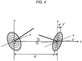
- the displacement amount of an actual M-UCA is defined by a y-axis symmetric rotation angle ⁇ , an x-axis symmetric rotation angle ⁇ , and a relative z-axis symmetric rotation angle ⁇ between transmitting and receiving antennae.
- a rotation order is as described.
- a distance d between the transmitting and receiving antennae is also estimated when the distance is unknown.
- R x ⁇ 1 0 0 0 0 cos ⁇ ⁇ sin ⁇ 0 sin ⁇ cos ⁇
- R y ⁇ cos ⁇ 0 sin ⁇ 0 1 0 ⁇ sin ⁇ 0 cos ⁇
- R Z ⁇ cos ⁇ ⁇ sin ⁇ 0 sin ⁇ cos ⁇ 0 0 0 1
- a value of a propagation channel between the transmitting and receiving antenna elements when the displacement as shown in FIG. 3 occurs can be calculated as follows. ⁇ 2 4 ⁇ d a , b 1 2 ⁇ d a , b + 1 i ⁇ exp ⁇ 2 i ⁇ d a , b
- ⁇ is a wavelength of an electromagnetic wave.
- d a,b which is a distance between the receiving antenna element a and the transmitting antenna element b, is expressed as follows.
- d a , b norm V ′ rx , a ⁇ V ′ tx , b
- a propagation channel matrix H between the transmitting and receiving antennae is expressed as follows.
- H h 1,1 ⁇ h 1 , M TX ⁇ ⁇ ⁇ h M RX , 1 ⁇ h M RX , M TX
- a partial channel matrix hm,n is a matrix of N RX (m) ⁇ N TX (n), and indicates the propagation channel between the m-th receiving UCA21-m and the n-th transmitting UCA 15-n.
- m 1, 2, ..., and M RX
- n 1, 2, ..., and M TX .
- the channel matrix between the antennae is a circulant matrix.
- the propagation channel h m,n between the respective UCAs may be subjected to singular value decomposition by using a discrete Fourier transform (DFT) matrix D N ⁇ C N ⁇ N , as follows.
- DFT discrete Fourier transform
- x and y used in Equations (5) and (6) respectively indicate indexes of a row and a column of each of the matrix ⁇ and the matrix D.
- the same expression is used for an index of a matrix or a vector.
- l(x) which is a value of an eigenmode in a circumferential direction dimension corresponding to an eigenvector of x rows of the DFT matrix, indicates the OAM mode.
- Equation (5) the number of singular values of the propagation channel between the respective UCAs is min[N RX (m), N TX (n)].
- the propagation channel between the m-th receiving UCA21-m and the n-th transmitting UCA 15-n is orthogonalized as in Equation (7), and thereby min[N RX (m), N TX (n)] independent transmission paths can be secured.
- ⁇ m , n D N TX n H h m , n D N RX m
- Equation (7) represents OAM mode generation and separation processes which are processes corresponding to the discrete Fourier transform and the inverse transform.
- Equation (8) H l 1 , l 1 ⁇ H l 1 , l L ⁇ ⁇ ⁇ H l L , l 1 ⁇ H l L , l L
- H l(x),l(y) is a channel between OAM modes l(x) and l(y), and is expressed by Equation (9).
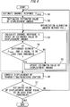
- FIG. 5 shows an example of a procedure of the displacement estimation process according to the present invention.
- the channel estimation unit estimates a measured channel response ⁇ meas corresponding to the channel response A in Equation (8) (S1).
- the measured channel response ⁇ meas corresponds to the channel response of not only an actual propagation channel but also a channel between an output port of the transmitting weight multiplication unit 13 and an input port of the receiving weight multiplication unit 23 including the OAM mode generation unit 14 and the OAM mode separation unit 22.
- the displacement amount estimation unit 27 initializes an estimated value of the displacement amount to a value such as 0 (S2), and then calculates the theoretical channel matrix A based on the above-described equations by using the initialized estimated value of the displacement amount (S3).
- the theoretical channel matrix A and the evaluation function including the theoretical channel matrix are "functions having the estimated value of the displacement amount as a variable.” Therefore, a value of the evaluation function can be reduced by updating the estimated value of the displacement amount being a value of an iteration variable by the use of an optimization algorithm such as a gradient method, a Newton method, a genetic algorithm, and many others. Then, the estimated value of the displacement amount when the value of the evaluation function becomes less than a predetermined value is determined as the displacement amount.
- the displacement correction unit adjusts a jig or the like of the antenna based on the estimated displacement amount to correct the displacement of each of the transmitting station and the receiving station (S6).
- the above-described processes may be repeatedly performed a predetermined number of times or until the magnitude of the estimated value of the displacement amount becomes equal to or less than a desired threshold (S7).
- the propagation channel between the antenna elements in a normal line-of-sight situation a great difference may scarcely occur in the magnitude of each element, but, in the above case, a bias occurs in the value of the channel response by performing the OAM mode generation and separation processes expressed by Equation (3). Therefore, it is possible to estimate the displacement amount with high accuracy by using only the element where sufficiently high energy is obtained without using all elements in computation of the function to be minimized. In this case, it is not necessary to estimate the channel for all available OAM modes.
- the channel may be estimated for only an OAM mode corresponding to the element of the propagation channel matrix used for estimating the actual displacement amount.
- any linear transform process or the like is included in a process required for communication, a linear transform process that can reduce a computation amount, or the channel response to be measured, the theoretical channel response A including influence of such the process may be used for computation.
- evaluation of the evaluation function using the propagation channel at a specific frequency is performed.
- channel information in a plurality of frequencies can be acquired as in a case of orthogonal frequency division multiplexing (OFDM), for example, the channel matrix in the evaluation function may be expanded by the number of frequency channels that can be used for estimation.
- OFDM orthogonal frequency division multiplexing
- the displacement amount is estimated by evaluating the evaluation function using intensities of the theoretical propagation channel and the measured propagation channel.
- the displacement amount is estimated by evaluating the following function.
- the displacement amount is estimated by minimizing the difference in intensity or complex amplitude between the theoretical propagation channel and the measured propagation channel.
- the evaluation function of Embodiment 1 using the intensity is first used to calculate an approximate value of the displacement, particularly a distance between antennae. After that, the approximate value is set as an initial value and the evaluation function of Embodiment 2 using the complex amplitude is used. It is thus possible to estimate the displacement amount with high accuracy without causing a wrong local optimum solution.
- Embodiment 1 to Embodiment 3 are not limited to the OAM multiplex transmission technique using the uniform circular array.
- the displacement amount can be defined and estimated by setting a coordinate axis in any array antenna.
- the displacement amount can be estimated by calculating a pure ideal propagation channel matrix H between the antenna elements, and using the propagation channel matrix H and the measured channel matrix H meas to evaluate the evaluation function as in the following Equation (12), for example.
- Embodiment 5 is different from Embodiments 1 to 4 in that the transmitting and receiving antennae can transmit and receive different polarized waves separately.
- the propagation channel between the receiving antenna element a and the transmitting antenna element b is expressed as a partial channel matrix using two polarized waves orthogonal to each other, as follows.
- X tx R z ⁇ ⁇ / 2 ⁇ R x ⁇ tx ⁇ R y ⁇ tx ⁇ 1 0
Landscapes
- Engineering & Computer Science (AREA)
- Computer Networks & Wireless Communication (AREA)
- Signal Processing (AREA)
- Physics & Mathematics (AREA)
- Electromagnetism (AREA)
- Power Engineering (AREA)
- Variable-Direction Aerials And Aerial Arrays (AREA)
Abstract
Description
- The present invention relates to an antenna displacement correction method and an antenna displacement correction device for an OAM multiplexing communication system subjecting a radio signal to spatial multiplex transmission by using orbital angular momentum (OAM) of an electromagnetic wave.
- In recent years, in order to improve a transmission capacity in communication between two points, that is, point to point (P2P) communication, a spatial multiplex transmission technique of multiplexing a signal in a line-of-sight situation has been reported. For example, in an OAM multiplexing communication system, signals in respective OAM modes modulated with different signal sequences are separated in a receiving station by using a property that spatial phase distributions of beams having different OAM modes are orthogonal to each other, and thus the signals can be subjected to spatial multiplex transmission in a line-of-sight situation.
- In
Non-Patent Document 1 that is one of specific reports, beams radiated from a plurality of Horn antennae are converted into different OAM modes and coaxially combined with each other by a phase plate, to be transmitted, and thus signals are successfully subjected to coaxial multiplex transmission. InNon-Patent Document 2, there is a report in which a plurality of OAM modes are generated by using a uniform circular array (UCA), and thus spatial multiplex transmission of signals is performed. - Non-Patent Document 1: J. Wang et al., "Terabit free-space data transmission employing orbital angular momentum multiplexing," Nature Photonics, Vol. 6, pp. 488 to 496, July 2012. Non-Patent Document 2: Z. Li, Y Ohashi, K. Kasai, "A dual-channel wireless communication system by multiplexing twisted radio wave," Proceedings of 44th European Microwave Conference, pp. 235 to 238, Oct. 2014.
- Antennae for transmitting and receiving beams having OAM modes are required to be disposed to face each other. If a displacement with respect to a predetermined relative positional relationship indicating the facing state occurs, the orthogonality between the OAM modes is broken, and thus inter-mode interference is caused. However, it is hard to remove the fine displacement by performing adjustment with the eyes, and a method and a device for estimating and correcting a displacement amount with high accuracy are required.
- An object of the present invention is to provide an antenna displacement correction method and an antenna displacement correction device for an OAM multiplexing communication system that can estimate and correct a displacement amount with respect to a predetermined relative positional relationship, regarding a transmitting antenna and a receiving antenna disposed in a line-of-sight situation.
- A first invention is directed to an antenna displacement correction method for an OAM multiplexing communication system that performs spatial multiplex transmission by using different spatial multiplex modes between a transmitting antenna and a receiving antenna respectively included in a transmitting station and a receiving station disposed to face each other in a line-of-sight situation. The antenna displacement correction method includes: a displacement amount estimation step that estimates a displacement amount by evaluating an evaluation function defined such that a theoretical channel response between the transmitting antenna and the receiving antenna matches a measured channel response estimated in the receiving station by using a known signal transmitted from the transmitting station, wherein the theoretical channel response has, as a parameter, the displacement amount indicating an amount of displacement of a reference axis predefined for each of the transmitting antenna and the receiving antenna from a predetermined position with respect to a desired relative positional relationship between the transmitting antenna and the receiving antenna; and a displacement correction step that corrects a displacement of each of the transmitting antenna and the receiving antenna according to the estimated displacement amount.
- In the antenna displacement correction method of the first invention, each of the transmitting antenna and the receiving antenna includes a single equal-interval uniform circular array (UCA) or a plurality of UCAs disposed concentrically. The displacement amount estimation step: includes a step that performs, in the transmitting station and the receiving station, processes corresponding to discrete Fourier transform and inverse transform with a same magnitude as a number of antenna elements of the UCA with respect to each propagation channel formed between the UCAs of the transmitting antenna and the receiving antenna; and estimates the displacement amount by evaluating the evaluation function that is defined by using a channel response including the processes corresponding to the discrete Fourier transform and the inverse transform.
- In the antenna displacement correction method of the first invention, the evaluation function may be an absolute value of a difference in one or more corresponding elements between the theoretical channel response and the measured channel response. The evaluation function may be an absolute value of a difference in magnitude of one or more corresponding elements between the theoretical channel response and the measured channel response. The displacement amount may be estimated by using different frequencies, different polarized waves, or both thereof.
- A second invention is directed to an antenna displacement correction device for an OAM multiplexing communication system that performs spatial multiplex transmission by using different spatial multiplex modes between a transmitting antenna and a receiving antenna respectively included in a transmitting station and a receiving station disposed to face each other in a line-of-sight situation, the antenna displacement correction device comprising. The antenna displacement correction device includes: a displacement amount estimation unit that estimates a displacement amount by evaluating an evaluation function defined such that a theoretical channel response between the transmitting antenna and the receiving antenna matches a measured channel response estimated in the receiving station by using a known signal transmitted from the transmitting station, wherein the theoretical channel response has, as a parameter, the displacement amount indicating an amount of displacement of a reference axis predefined for each of the transmitting antenna and the receiving antenna from a predetermined position with respect to a desired relative positional relationship between the transmitting antenna and the receiving antenna; and a displacement correction unit that corrects a displacement of each of the transmitting antenna and the receiving antenna according to the estimated displacement amount.
- In the antenna displacement correction device of the second invention, each of the transmitting antenna and the receiving antenna includes a single equal-interval uniform circular array (UCA) or a plurality of UCAs disposed concentrically. The displacement amount estimation unit: includes a unit that performs, in the transmitting station and the receiving station, processes corresponding to discrete Fourier transform and inverse transform with a same magnitude as a number of antenna elements of the UCA with respect to each propagation channel formed between the UCAs of the transmitting antenna and the receiving antenna; and estimates the displacement amount by evaluating the evaluation function that is defined by using a channel response including the processes corresponding to the discrete Fourier transform and the inverse transform.
- According to the present invention, it is possible to estimate and correct the displacement amount by minimizing a difference between theoretical propagation channel information having the displacement amount with respect to the predetermined relative positional relationship as a parameter and measured propagation channel information.
- Accordingly, since the displacement amount can be estimated and corrected with high accuracy, inter-mode interference can be reduced and improvement in a system throughput and frequency use efficiency is expected.
-
-
FIG. 1 is a diagram showing a configuration example of an M-UCA of an OAM multiplexing communication system according to the present invention. -
FIG. 2 is a diagram showing a configuration example of the OAM multiplexing communication system according to the present invention. -
FIG. 3 is a diagram showing definition of a displacement of transmitting and receiving antennae. -
FIG. 4 is a diagram showing definition of a displacement of transmitting and receiving antennae. -
FIG. 5 is a flowchart showing an example of a procedure of a displacement estimation process according to the present invention. -
FIG. 1 shows a configuration example of an M-UCA of an OAM multiplexing communication system according to the present invention. - In
FIG. 1 , the M-UCA has a configuration in which a plurality of UCAs are disposed concentrically. Herein, a configuration in which four UCAs having different radii are disposed is illustrated, and the UCAs are referred to as a first UCA, a second UCA, a third UCA, and a fourth UCA in this order from the inner. As an example, each UCA includes 16 antenna elements (indicated by • inFIG. 1 ), but the number of antenna elements of each UCA is not necessarily required to be the same. The antenna element constituting the M-UCA may be Horn antennae, patch antennae, or other antennae. -
FIG. 2 shows a configuration example of the OAM multiplexing communication system according to the present invention. - In
FIG. 2 , a transmittingstation 10 includes a plurality of MTX UCAs such as a first transmitting UCA 15-1 to an MTX-th transmitting UCA 15-MTX, and the respective numbers of transmitting antenna elements are NTX(1) to NTX(MTX). A signal processing unit 11 receives a transmission signal sequence, and generates Mi to ML signals respectively transmitted inOAM modes # 1 to #L. A transmittingweight multiplication unit 12 multiplies each signal generated by the signal processing unit 11 by a transmitting weight to generate signals to be transmitted in theOAM modes # 1 to #L from each UCA. Each of a first OAM mode generation unit 14-1 to an MTX-th OAM mode generation unit 14-MTX receives the signals to be transmitted in theOAM modes # 1 to #L, adjusts phases of the signals to be transmitted as signals in theOAM modes # 1 to #L, and inputs the signals to the antenna elements of each UCA. - A
receiving station 20 includes a plurality of MRX UCAs such as a first receiving UCA 21-1 to an MRX-th receiving UCA 21-MRX, and the respective numbers of receiving antenna elements are NRX(1) to NRX(MRX). A first OAM mode separation unit 22-1 to an MRX-th OAM mode separation unit 22-MRX separate signals in theOAM modes # 1 to #L from signals received by the first receiving UCA 21-1 to the MRX-th receiving UCA 21 -MRX, respectively. A receivingweight multiplication unit 23 receives the signals in theOAM modes # 1 to #L separated for each UCA, collects the signals for each OAM mode, multiplies the signals by respective receiving weights, and outputs the signals as M1 to ML signals. Asignal processing unit 25 demodulates the signal received in each UCA and each OAM mode, and outputs a received signal sequence. - Moreover, the
receiving station 20 includes a channel estimation/receivingweight calculation unit 26 that estimates channel information and calculates a receiving weight by using output signals from the first OAM mode separation unit 22-1 to the MRX-th OAM mode separation unit 22-MRX. The channel estimation/receivingweight calculation unit 26 sets the calculated receiving weight for the receivingweight multiplication unit 23, and outputs the measured channel information to a displacementamount estimation unit 27. The displacementamount estimation unit 27 estimates a displacement amount by using the measured channel information, notifies adisplacement correction unit 28 of the displacement amount, and also notifies adisplacement correction unit 16 of thetransmitting station 10 of the displacement amount via afeedback unit 29. The channel information and a transmitting weight estimated by the channel estimation/receivingweight calculation unit 26 are set for the transmittingweight multiplication unit 12 of the transmittingstation 10 via thefeedback unit 29. - Each of the
displacement correction unit 28 of thereceiving station 20 and thedisplacement correction unit 16 of thetransmitting station 10 includes an automatic or manual displacement correction mechanism, and corrects a displacement based on the notified displacement amount. - The transmitting
weight multiplication unit 12, the receivingweight multiplication unit 23, the first OAM mode generation unit 14-1 to the MTX-th OAM mode generation unit 14-MTX, and the first OAM mode separation unit 22-1 to the MRX-th OAM mode separation unit 22-MRX may perform either one of digital signal processing and analog signal processing, and a DA converter or an AD converter is disposed at an appropriate position according to each processing method. The first OAM mode generation unit 14-1 to the MTX-th OAM mode generation unit 14-MTX of the transmittingstation 10, and the first OAM mode separation unit 22-1 to the MRX-th OAM mode separation unit 22-MRX of thereceiving station 20 are sequentially coupled to the antenna elements of the respectively corresponding UCAs in the same rotational direction. - First, a displacement amount may be defined by way of taking coordinate axes depending on a shape of an antenna fixing jig or the like In the present embodiment, the displacement amount is defined by the following parameters.
- As shown in
FIGS. 3 and4 , when an original M-UCA is ideally disposed on an xy plane and is disposed such that a propagation axis of a beam having OAM is a z axis, the displacement amount of an actual M-UCA is defined by a y-axis symmetric rotation angle θ, an x-axis symmetric rotation angle ϕ, and a relative z-axis symmetric rotation angle ψ between transmitting and receiving antennae. A rotation order is as described. A distance d between the transmitting and receiving antennae is also estimated when the distance is unknown. - When a coordinate of a receiving antenna element a in a complete facing state is Vrx,a, and a coordinate of a transmitting antenna element b in the complete facing state is Vtx,b, a coordinate V'rx,a of the receiving antenna element and a coordinate V'tx,b of the transmitting antenna element including the displacement can be expressed as follows.


- In this case, a value of a propagation channel between the transmitting and receiving antenna elements when the displacement as shown in
FIG. 3 occurs can be calculated as follows.
- Here, λ is a wavelength of an electromagnetic wave. In addition, da,b, which is a distance between the receiving antenna element a and the transmitting antenna element b, is expressed as follows.

- In view of the above, a propagation channel matrix H between the transmitting and receiving antennae is expressed as follows.

- A partial channel matrix hm,n is a matrix of NRX(m)×NTX(n), and indicates the propagation channel between the m-th receiving UCA21-m and the n-th transmitting UCA 15-n. Here, m = 1, 2, ..., and MRX, and n = 1, 2, ..., and MTX.
- Since rotational symmetry occurs with respect to the propagation axis when the transmitting antenna and the receiving antenna are disposed to face each other, the channel matrix between the antennae is a circulant matrix. Thus, due to the property of the circulant matrix, the propagation channel hm,n between the respective UCAs may be subjected to singular value decomposition by using a discrete Fourier transform (DFT) matrix DN ∈ CN∗N, as follows.


- It should be noted that x and y used in Equations (5) and (6) respectively indicate indexes of a row and a column of each of the matrix Σ and the matrix D. Hereinafter, the same expression is used for an index of a matrix or a vector. In addition, l(x), which is a value of an eigenmode in a circumferential direction dimension corresponding to an eigenvector of x rows of the DFT matrix, indicates the OAM mode.
- In this case, from Equation (5), the number of singular values of the propagation channel between the respective UCAs is min[NRX(m), NTX(n)]. Thus, the propagation channel between the m-th receiving UCA21-m and the n-th transmitting UCA 15-n is orthogonalized as in Equation (7), and thereby min[NRX(m), NTX(n)] independent transmission paths can be secured.

- Equation (7) represents OAM mode generation and separation processes which are processes corresponding to the discrete Fourier transform and the inverse transform.
- Next, when L is set to min(NRX, NTX), a channel response A including the OAM mode generation and separation processes is formed as in Equation (8).

- Here, Hl(x),l(y) is a channel between OAM modes l(x) and l(y), and is expressed by Equation (9).

-
FIG. 5 shows an example of a procedure of the displacement estimation process according to the present invention. - In
FIG. 5 , first, the channel estimation unit estimates a measured channel response Λmeas corresponding to the channel response A in Equation (8) (S1). The measured channel response Λmeas corresponds to the channel response of not only an actual propagation channel but also a channel between an output port of the transmitting weight multiplication unit 13 and an input port of the receivingweight multiplication unit 23 including the OAMmode generation unit 14 and the OAMmode separation unit 22. - Next, the displacement
amount estimation unit 27 initializes an estimated value of the displacement amount to a value such as 0 (S2), and then calculates the theoretical channel matrix A based on the above-described equations by using the initialized estimated value of the displacement amount (S3). - Then, a difference in magnitude between the obtained theoretical channel matrix A and the measured channel response Λmeas is calculated, and an estimated value of the displacement amount that minimizes the difference is calculated (S4 and S5). In other words, the following evaluation function is evaluated.

- Here, the theoretical channel matrix A and the evaluation function including the theoretical channel matrix are "functions having the estimated value of the displacement amount as a variable." Therefore, a value of the evaluation function can be reduced by updating the estimated value of the displacement amount being a value of an iteration variable by the use of an optimization algorithm such as a gradient method, a Newton method, a genetic algorithm, and many others. Then, the estimated value of the displacement amount when the value of the evaluation function becomes less than a predetermined value is determined as the displacement amount.
- More specifically, when the initial value of the estimated value of the displacement amount is set as follows, a value of ΛH×Λ is uniquely defined. Moreover, the value of Λmeas H×Λmeas is obtained through measurement.
- Finally, the displacement correction unit adjusts a jig or the like of the antenna based on the estimated displacement amount to correct the displacement of each of the transmitting station and the receiving station (S6).
- In order to increase accuracy of the displacement correction, the above-described processes may be repeatedly performed a predetermined number of times or until the magnitude of the estimated value of the displacement amount becomes equal to or less than a desired threshold (S7).
- Here, with regard to the propagation channel between the antenna elements in a normal line-of-sight situation, a great difference may scarcely occur in the magnitude of each element, but, in the above case, a bias occurs in the value of the channel response by performing the OAM mode generation and separation processes expressed by Equation (3). Therefore, it is possible to estimate the displacement amount with high accuracy by using only the element where sufficiently high energy is obtained without using all elements in computation of the function to be minimized. In this case, it is not necessary to estimate the channel for all available OAM modes. The channel may be estimated for only an OAM mode corresponding to the element of the propagation channel matrix used for estimating the actual displacement amount.
- When any linear transform process or the like is included in a process required for communication, a linear transform process that can reduce a computation amount, or the channel response to be measured, the theoretical channel response A including influence of such the process may be used for computation.
- In the present embodiment, evaluation of the evaluation function using the propagation channel at a specific frequency is performed. When channel information in a plurality of frequencies can be acquired as in a case of orthogonal frequency division multiplexing (OFDM), for example, the channel matrix in the evaluation function may be expanded by the number of frequency channels that can be used for estimation.
- In
Embodiment 1, the displacement amount is estimated by evaluating the evaluation function using intensities of the theoretical propagation channel and the measured propagation channel. As another example, it is also possible to estimate the displacement amount by using minimization of an absolute value of a difference in a complex amplitude between the theoretical propagation channel and the measured propagation channel as the evaluation function. - In other words, the displacement amount is estimated by evaluating the following function.

- In
Embodiment 1 andEmbodiment 2, the displacement amount is estimated by minimizing the difference in intensity or complex amplitude between the theoretical propagation channel and the measured propagation channel. Each method has an advantage and a disadvantage. - First, in the case of the method using the complex amplitude, a phase greatly changes due to a small displacement of the coordinate axis. This becomes remarkable when a high frequency such as a millimeter wave is used. This leads to a situation in which a plurality of local minimum solutions are present in the evaluation function due to a periodic feature of the phase, and thus there is a high probability that a wrong solution may be derived unless an initial value close to a true solution is originally selected.
- On the other hand, in the case of the method using the intensity, a change due to the displacement is smooth, and a large error may be included in the estimated value due to the influence of noise or the like.
- In view of the above, in order to compensate for the disadvantages and utilize the advantages of both methods, the evaluation function of
Embodiment 1 using the intensity is first used to calculate an approximate value of the displacement, particularly a distance between antennae. After that, the approximate value is set as an initial value and the evaluation function ofEmbodiment 2 using the complex amplitude is used. It is thus possible to estimate the displacement amount with high accuracy without causing a wrong local optimum solution. - The methods of
Embodiment 1 toEmbodiment 3 are not limited to the OAM multiplex transmission technique using the uniform circular array. The displacement amount can be defined and estimated by setting a coordinate axis in any array antenna. - In particular, when weight multiplication or other transform processes are not included, the displacement amount can be estimated by calculating a pure ideal propagation channel matrix H between the antenna elements, and using the propagation channel matrix H and the measured channel matrix Hmeas to evaluate the evaluation function as in the following Equation (12), for example.

- This is an evaluation function equivalent to that of
Embodiment 1. Of course, an evaluation function equivalent to that ofEmbodiment 2 may be used instead. When any line transform process is included in the transmitting and receiving stations, computation may be performed in consideration of the influence thereof in the same manner as inEmbodiment 1. -
Embodiment 5 is different fromEmbodiments 1 to 4 in that the transmitting and receiving antennae can transmit and receive different polarized waves separately. - In this case, the propagation channel between the receiving antenna element a and the transmitting antenna element b is expressed as a partial channel matrix using two polarized waves orthogonal to each other, as follows.





- From the above description, expanding the equation as described above when calculating the theoretical channel response A makes it possible to cope with a case of using the antenna elements that can transmit and receive different polarized waves separately.
-
- 10
- TRANSMITTING STATION
- 11
- SIGNAL PROCESSING UNIT
- 12, 13
- TRANSMITTING WEIGHT MULTIPLICATION UNIT
- 14
- OAM MODE GENERATION UNIT
- 15
- TRANSMITTING UCA
- 16
- DISPLACEMENT CORRECTION UNIT
- 20
- RECEIVING STATION
- 21
- RECEIVING UCA
- 22
- OAM MODE SEPARATION UNIT
- 23
- RECEIVING WEIGHT MULTIPLICATION UNIT
- 25
- SIGNAL PROCESSING UNIT
- 26
- CHANNEL ESTIMATION/RECEIVING WEIGHT CALCULATION UNIT
- 27
- DISPLACEMENT AMOUNT ESTIMATION UNIT
- 28
- DISPLACEMENT CORRECTION UNIT
- 29
- FEEDBACK UNIT
Claims (7)
- An antenna displacement correction method for an OAM multiplexing communication system that performs spatial multiplex transmission by using different spatial multiplex modes between a transmitting antenna and a receiving antenna respectively included in a transmitting station and a receiving station disposed to face each other in a line-of-sight situation, the antenna displacement correction method comprising:a displacement amount estimation step that estimates a displacement amount by evaluating an evaluation function defined such that a theoretical channel response between the transmitting antenna and the receiving antenna matches a measured channel response estimated in the receiving station by using a known signal transmitted from the transmitting station, wherein the theoretical channel response has, as a parameter, the displacement amount indicating an amount of displacement of a reference axis predefined for each of the transmitting antenna and the receiving antenna from a predetermined position with respect to a desired relative positional relationship between the transmitting antenna and the receiving antenna; anda displacement correction step that corrects a displacement of each of the transmitting antenna and the receiving antenna according to the estimated displacement amount.
- The antenna displacement correction method for the OAM multiplexing communication system according to claim 1, wherein
each of the transmitting antenna and the receiving antenna includes a single equal-interval uniform circular array (UCA) or a plurality of UCAs disposed concentrically, and
the displacement amount estimation step:includes a step that performs, in the transmitting station and the receiving station, processes corresponding to discrete Fourier transform and inverse transform with a same magnitude as a number of antenna elements of the UCA with respect to each propagation channel formed between the UCAs of the transmitting antenna and the receiving antenna; andestimates the displacement amount by evaluating the evaluation function that is defined by using a channel response including the processes corresponding to the discrete Fourier transform and the inverse transform. - The antenna displacement correction method for the OAM multiplexing communication system according to claim 1 or 2, wherein
the evaluation function is an absolute value of a difference in one or more corresponding elements between the theoretical channel response and the measured channel response. - The antenna displacement correction method for the OAM multiplexing communication system according to claim 1 or 2, wherein
the evaluation function is an absolute value of a difference in magnitude of one or more corresponding elements between the theoretical channel response and the measured channel response. - The antenna displacement correction method for the OAM multiplexing communication system according to claim 1 or 2, wherein
the displacement amount is estimated by using different frequencies, different polarized waves, or both thereof. - An antenna displacement correction device for an OAM multiplexing communication system that performs spatial multiplex transmission by using different spatial multiplex modes between a transmitting antenna and a receiving antenna respectively included in a transmitting station and a receiving station disposed to face each other in a line-of-sight situation, the antenna displacement correction device comprising:a displacement amount estimation unit that estimates a displacement amount by evaluating an evaluation function defined such that a theoretical channel response between the transmitting antenna and the receiving antenna matches a measured channel response estimated in the receiving station by using a known signal transmitted from the transmitting station, wherein the theoretical channel response has, as a parameter, the displacement amount indicating an amount of displacement of a reference axis predefined for each of the transmitting antenna and the receiving antenna from a predetermined position with respect to a desired relative positional relationship between the transmitting antenna and the receiving antenna; anda displacement correction unit that corrects a displacement of each of the transmitting antenna and the receiving antenna according to the estimated displacement amount.
- The antenna displacement correction device for the OAM multiplexing communication system according to claim 6, wherein
each of the transmitting antenna and the receiving antenna includes a single equal-interval uniform circular array (UCA) or a plurality of UCAs disposed concentrically, and
the displacement amount estimation unit:includes a unit that performs, in the transmitting station and the receiving station, processes corresponding to discrete Fourier transform and inverse transform with a same magnitude as a number of antenna elements of the UCA with respect to each propagation channel formed between the UCAs of the transmitting antenna and the receiving antenna; andestimates the displacement amount by evaluating the evaluation function that is defined by using a channel response including the processes corresponding to the discrete Fourier transform and the inverse transform.
Applications Claiming Priority (2)
| Application Number | Priority Date | Filing Date | Title |
|---|---|---|---|
| JP2018069363 | 2018-03-30 | ||
| PCT/JP2019/013894 WO2019189704A1 (en) | 2018-03-30 | 2019-03-28 | Method and device for correcting positional deviation of antenna in oam multiplexed communication system |
Publications (3)
| Publication Number | Publication Date |
|---|---|
| EP3780428A1 true EP3780428A1 (en) | 2021-02-17 |
| EP3780428A4 EP3780428A4 (en) | 2022-01-05 |
| EP3780428B1 EP3780428B1 (en) | 2023-06-14 |
Family
ID=68059226
Family Applications (1)
| Application Number | Title | Priority Date | Filing Date |
|---|---|---|---|
| EP19775045.8A Active EP3780428B1 (en) | 2018-03-30 | 2019-03-28 | Method and device for correcting positional deviation of antenna in oam multiplexed communication system |
Country Status (5)
| Country | Link |
|---|---|
| US (1) | US11139867B2 (en) |
| EP (1) | EP3780428B1 (en) |
| JP (1) | JP6996619B2 (en) |
| CN (1) | CN111937328B (en) |
| WO (1) | WO2019189704A1 (en) |
Families Citing this family (12)
| Publication number | Priority date | Publication date | Assignee | Title |
|---|---|---|---|---|
| US11411325B2 (en) * | 2017-09-25 | 2022-08-09 | Nippon Telegraph And Telephone Corporation | OAM multiplexing communication system and OAM multiplexing communication method |
| CN111698014B (en) * | 2020-06-11 | 2023-09-26 | 上海磐启微电子有限公司 | an antenna array system |
| CN116458076A (en) * | 2020-11-23 | 2023-07-18 | 高通股份有限公司 | Techniques for determining orbital angular momentum emitter circles |
| US12231912B2 (en) * | 2021-06-18 | 2025-02-18 | Qualcomm Incorporated | System and method for reporting orbital angular momentum waveform misalignment |
| US11849469B2 (en) | 2021-06-18 | 2023-12-19 | Qualcomm Incorporated | Orbital angular momentum capability in millimeter wave and higher frequency bands |
| US11616555B2 (en) * | 2021-06-18 | 2023-03-28 | Qualcomm Incorporated | Spatial misalignment tracking for orbital angular momentum beams in millimeter wave and higher frequency bands |
| US11757516B2 (en) | 2021-06-18 | 2023-09-12 | Qualcomm Incorporated | Beam management procedure for OAM in MMW and higher bands |
| JP2023037799A (en) | 2021-09-06 | 2023-03-16 | 日本電気株式会社 | Oam mode multiplexing transmission apparatus, oam mode multiplexing radio transmission system, oam mode multiplexing transmission method, and program |
| WO2023047583A1 (en) * | 2021-09-27 | 2023-03-30 | 日本電信電話株式会社 | Wireless communication method, wireless communication device, and wireless communication system |
| US12261686B2 (en) * | 2022-03-03 | 2025-03-25 | Nec Corporation | Control apparatus, OAM mode-multiplexing transmitting apparatus, OAM mode-multiplexing receiving apparatus, control method, and non-transitory computer readable medium |
| WO2023166673A1 (en) * | 2022-03-03 | 2023-09-07 | 日本電気株式会社 | Control device, oam mode multiplex transmission device, oam mode multiplex reception device, control method, and non-transitory computer-readable medium |
| CN114553283B (en) * | 2022-03-07 | 2024-09-03 | 中国科学院上海微系统与信息技术研究所 | Vortex electromagnetic wave divergence angle adjusting method based on multi-circle UCA |
Family Cites Families (7)
| Publication number | Priority date | Publication date | Assignee | Title |
|---|---|---|---|---|
| JP4727678B2 (en) * | 2006-02-08 | 2011-07-20 | 富士通株式会社 | Wireless communication system using multi-antenna transmission technology and multi-user scheduler applied to the same |
| JP4784651B2 (en) * | 2009-01-08 | 2011-10-05 | ソニー株式会社 | COMMUNICATION DEVICE, COMMUNICATION SYSTEM, POSITION DETECTION METHOD, AND PROGRAM |
| KR20170022636A (en) * | 2015-08-21 | 2017-03-02 | 한국전자통신연구원 | Receiving apparatus of multi input multi output system and reception signal processing method |
| FR3042318B1 (en) * | 2015-10-07 | 2017-10-27 | Thales Sa | METHOD FOR CALIBRATING SECTORIZED ELECTRONIC SCANNING ANTENNA, AND MEASURING DEVICE FOR IMPLEMENTING SUCH A METHOD |
| US10411811B2 (en) * | 2015-12-07 | 2019-09-10 | University Of Southern California | Systems and techniques for communication using combined orbital angular momentum and multiple-input-multiple-output processing |
| US10680728B2 (en) * | 2016-06-09 | 2020-06-09 | Nec Corporation | Radio communication system, receiving apparatus, correction apparatus, antenna correction method and program |
| WO2018112879A1 (en) * | 2016-12-23 | 2018-06-28 | Telefonaktiebolaget Lm Ericsson (Publ) | Antenna calibration for multiple input multiple output |
-
2019
- 2019-03-28 WO PCT/JP2019/013894 patent/WO2019189704A1/en not_active Ceased
- 2019-03-28 JP JP2020511058A patent/JP6996619B2/en active Active
- 2019-03-28 CN CN201980022969.XA patent/CN111937328B/en active Active
- 2019-03-28 US US17/042,703 patent/US11139867B2/en active Active
- 2019-03-28 EP EP19775045.8A patent/EP3780428B1/en active Active
Also Published As
| Publication number | Publication date |
|---|---|
| EP3780428B1 (en) | 2023-06-14 |
| JPWO2019189704A1 (en) | 2021-02-12 |
| JP6996619B2 (en) | 2022-01-17 |
| WO2019189704A1 (en) | 2019-10-03 |
| CN111937328B (en) | 2023-03-24 |
| US20210058118A1 (en) | 2021-02-25 |
| CN111937328A (en) | 2020-11-13 |
| EP3780428A4 (en) | 2022-01-05 |
| US11139867B2 (en) | 2021-10-05 |
Similar Documents
| Publication | Publication Date | Title |
|---|---|---|
| EP3780428B1 (en) | Method and device for correcting positional deviation of antenna in oam multiplexed communication system | |
| US11202211B2 (en) | OAM multiplexing communication system and OAM multiplexing communication method | |
| US11228363B2 (en) | OAM multiplexing communication system and inter-mode interference elimination method | |
| Kwon et al. | Joint communication and localization in millimeter wave networks | |
| EP4207491A1 (en) | Electronic device, wireless communication method and computer-readable storage medium | |
| EP3577783B1 (en) | Beamforming codebook adaption to antenna array imperfections | |
| EP3780431B1 (en) | Oam multiplexed communication system and inter-mode interference control method | |
| US11368198B2 (en) | Calibration control apparatus, calibration control method, non-transitory computer readable medium, and calibration system | |
| US20200382346A1 (en) | Efficient sparse channel estimation based on compressed sensing | |
| CN107210798B (en) | Microwave radio transmitter for compensating phase noise and related method | |
| EP3780430A1 (en) | Oam multiplexed communication system and inter-mode interference compensation method | |
| KR20180060882A (en) | Apparatus and method for transmitting signal using beamforming in wireless communication system | |
| US9762307B2 (en) | Communication system and communication control method using interference channel matrix | |
| Zhu et al. | Auxiliary beam pair enabled AoD and AoA estimation in mmWave FD-MIMO systems | |
| Chiang et al. | Low-complexity spatial channel estimation and hybrid beamforming for millimeter wave links | |
| Luo et al. | Tensor-Based Framework for Multi-User RIS-Assisted ISAC in Cross Far-and Near-Field Communications | |
| EP2398111B1 (en) | Calibration device | |
| Meng et al. | Sensing assisted predictive beamforming for v2i networks: Tracking on the complicated road | |
| Duong et al. | Sparse Bayesian learning with atom refinement for mmWave MIMO channel estimation | |
| EP4661531A1 (en) | Electronic device and method for providing angle of arrival in wireless communication system | |
| Igbafe et al. | Location-aware beam alignment for mmWave communications | |
| Yan et al. | Tracking sparse mmWave channel: Performance analysis under intra-cluster angular spread | |
| JP2017147630A (en) | Array antenna system, array control method, antenna device, and array control device | |
| Luo et al. | How to calibrate massive MIMO? | |
| Seo et al. | Aerial RIS-assisted direction finding under doppler effect based on atomic norm minimization |
Legal Events
| Date | Code | Title | Description |
|---|---|---|---|
| STAA | Information on the status of an ep patent application or granted ep patent |
Free format text: STATUS: THE INTERNATIONAL PUBLICATION HAS BEEN MADE |
|
| PUAI | Public reference made under article 153(3) epc to a published international application that has entered the european phase |
Free format text: ORIGINAL CODE: 0009012 |
|
| STAA | Information on the status of an ep patent application or granted ep patent |
Free format text: STATUS: REQUEST FOR EXAMINATION WAS MADE |
|
| 17P | Request for examination filed |
Effective date: 20200914 |
|
| AK | Designated contracting states |
Kind code of ref document: A1 Designated state(s): AL AT BE BG CH CY CZ DE DK EE ES FI FR GB GR HR HU IE IS IT LI LT LU LV MC MK MT NL NO PL PT RO RS SE SI SK SM TR |
|
| AX | Request for extension of the european patent |
Extension state: BA ME |
|
| DAV | Request for validation of the european patent (deleted) | ||
| DAX | Request for extension of the european patent (deleted) | ||
| A4 | Supplementary search report drawn up and despatched |
Effective date: 20211203 |
|
| RIC1 | Information provided on ipc code assigned before grant |
Ipc: H04B 7/08 20060101ALI20211129BHEP Ipc: H04B 7/06 20060101ALI20211129BHEP Ipc: H04B 7/0417 20170101ALI20211129BHEP Ipc: H04J 14/04 20060101ALI20211129BHEP Ipc: H04B 10/516 20130101ALI20211129BHEP Ipc: H04B 10/112 20130101ALI20211129BHEP Ipc: H04B 7/0413 20170101ALI20211129BHEP Ipc: H01Q 21/20 20060101ALI20211129BHEP Ipc: H04J 99/00 20090101AFI20211129BHEP |
|
| STAA | Information on the status of an ep patent application or granted ep patent |
Free format text: STATUS: EXAMINATION IS IN PROGRESS |
|
| 17Q | First examination report despatched |
Effective date: 20220628 |
|
| GRAP | Despatch of communication of intention to grant a patent |
Free format text: ORIGINAL CODE: EPIDOSNIGR1 |
|
| STAA | Information on the status of an ep patent application or granted ep patent |
Free format text: STATUS: GRANT OF PATENT IS INTENDED |
|
| INTG | Intention to grant announced |
Effective date: 20230222 |
|
| GRAS | Grant fee paid |
Free format text: ORIGINAL CODE: EPIDOSNIGR3 |
|
| GRAA | (expected) grant |
Free format text: ORIGINAL CODE: 0009210 |
|
| STAA | Information on the status of an ep patent application or granted ep patent |
Free format text: STATUS: THE PATENT HAS BEEN GRANTED |
|
| AK | Designated contracting states |
Kind code of ref document: B1 Designated state(s): AL AT BE BG CH CY CZ DE DK EE ES FI FR GB GR HR HU IE IS IT LI LT LU LV MC MK MT NL NO PL PT RO RS SE SI SK SM TR |
|
| REG | Reference to a national code |
Ref country code: CH Ref legal event code: EP |
|
| REG | Reference to a national code |
Ref country code: DE Ref legal event code: R096 Ref document number: 602019031091 Country of ref document: DE |
|
| REG | Reference to a national code |
Ref country code: AT Ref legal event code: REF Ref document number: 1579997 Country of ref document: AT Kind code of ref document: T Effective date: 20230715 |
|
| REG | Reference to a national code |
Ref country code: LT Ref legal event code: MG9D |
|
| REG | Reference to a national code |
Ref country code: NL Ref legal event code: MP Effective date: 20230614 |
|
| PG25 | Lapsed in a contracting state [announced via postgrant information from national office to epo] |
Ref country code: SE Free format text: LAPSE BECAUSE OF FAILURE TO SUBMIT A TRANSLATION OF THE DESCRIPTION OR TO PAY THE FEE WITHIN THE PRESCRIBED TIME-LIMIT Effective date: 20230614 Ref country code: NO Free format text: LAPSE BECAUSE OF FAILURE TO SUBMIT A TRANSLATION OF THE DESCRIPTION OR TO PAY THE FEE WITHIN THE PRESCRIBED TIME-LIMIT Effective date: 20230914 Ref country code: ES Free format text: LAPSE BECAUSE OF FAILURE TO SUBMIT A TRANSLATION OF THE DESCRIPTION OR TO PAY THE FEE WITHIN THE PRESCRIBED TIME-LIMIT Effective date: 20230614 |
|
| REG | Reference to a national code |
Ref country code: AT Ref legal event code: MK05 Ref document number: 1579997 Country of ref document: AT Kind code of ref document: T Effective date: 20230614 |
|
| PG25 | Lapsed in a contracting state [announced via postgrant information from national office to epo] |
Ref country code: RS Free format text: LAPSE BECAUSE OF FAILURE TO SUBMIT A TRANSLATION OF THE DESCRIPTION OR TO PAY THE FEE WITHIN THE PRESCRIBED TIME-LIMIT Effective date: 20230614 Ref country code: NL Free format text: LAPSE BECAUSE OF FAILURE TO SUBMIT A TRANSLATION OF THE DESCRIPTION OR TO PAY THE FEE WITHIN THE PRESCRIBED TIME-LIMIT Effective date: 20230614 Ref country code: LV Free format text: LAPSE BECAUSE OF FAILURE TO SUBMIT A TRANSLATION OF THE DESCRIPTION OR TO PAY THE FEE WITHIN THE PRESCRIBED TIME-LIMIT Effective date: 20230614 Ref country code: LT Free format text: LAPSE BECAUSE OF FAILURE TO SUBMIT A TRANSLATION OF THE DESCRIPTION OR TO PAY THE FEE WITHIN THE PRESCRIBED TIME-LIMIT Effective date: 20230614 Ref country code: HR Free format text: LAPSE BECAUSE OF FAILURE TO SUBMIT A TRANSLATION OF THE DESCRIPTION OR TO PAY THE FEE WITHIN THE PRESCRIBED TIME-LIMIT Effective date: 20230614 Ref country code: GR Free format text: LAPSE BECAUSE OF FAILURE TO SUBMIT A TRANSLATION OF THE DESCRIPTION OR TO PAY THE FEE WITHIN THE PRESCRIBED TIME-LIMIT Effective date: 20230915 |
|
| PG25 | Lapsed in a contracting state [announced via postgrant information from national office to epo] |
Ref country code: FI Free format text: LAPSE BECAUSE OF FAILURE TO SUBMIT A TRANSLATION OF THE DESCRIPTION OR TO PAY THE FEE WITHIN THE PRESCRIBED TIME-LIMIT Effective date: 20230614 |
|
| PG25 | Lapsed in a contracting state [announced via postgrant information from national office to epo] |
Ref country code: SK Free format text: LAPSE BECAUSE OF FAILURE TO SUBMIT A TRANSLATION OF THE DESCRIPTION OR TO PAY THE FEE WITHIN THE PRESCRIBED TIME-LIMIT Effective date: 20230614 |
|
| PG25 | Lapsed in a contracting state [announced via postgrant information from national office to epo] |
Ref country code: IS Free format text: LAPSE BECAUSE OF FAILURE TO SUBMIT A TRANSLATION OF THE DESCRIPTION OR TO PAY THE FEE WITHIN THE PRESCRIBED TIME-LIMIT Effective date: 20231014 |
|
| PG25 | Lapsed in a contracting state [announced via postgrant information from national office to epo] |
Ref country code: SM Free format text: LAPSE BECAUSE OF FAILURE TO SUBMIT A TRANSLATION OF THE DESCRIPTION OR TO PAY THE FEE WITHIN THE PRESCRIBED TIME-LIMIT Effective date: 20230614 Ref country code: SK Free format text: LAPSE BECAUSE OF FAILURE TO SUBMIT A TRANSLATION OF THE DESCRIPTION OR TO PAY THE FEE WITHIN THE PRESCRIBED TIME-LIMIT Effective date: 20230614 Ref country code: RO Free format text: LAPSE BECAUSE OF FAILURE TO SUBMIT A TRANSLATION OF THE DESCRIPTION OR TO PAY THE FEE WITHIN THE PRESCRIBED TIME-LIMIT Effective date: 20230614 Ref country code: PT Free format text: LAPSE BECAUSE OF FAILURE TO SUBMIT A TRANSLATION OF THE DESCRIPTION OR TO PAY THE FEE WITHIN THE PRESCRIBED TIME-LIMIT Effective date: 20231016 Ref country code: IS Free format text: LAPSE BECAUSE OF FAILURE TO SUBMIT A TRANSLATION OF THE DESCRIPTION OR TO PAY THE FEE WITHIN THE PRESCRIBED TIME-LIMIT Effective date: 20231014 Ref country code: EE Free format text: LAPSE BECAUSE OF FAILURE TO SUBMIT A TRANSLATION OF THE DESCRIPTION OR TO PAY THE FEE WITHIN THE PRESCRIBED TIME-LIMIT Effective date: 20230614 Ref country code: CZ Free format text: LAPSE BECAUSE OF FAILURE TO SUBMIT A TRANSLATION OF THE DESCRIPTION OR TO PAY THE FEE WITHIN THE PRESCRIBED TIME-LIMIT Effective date: 20230614 Ref country code: AT Free format text: LAPSE BECAUSE OF FAILURE TO SUBMIT A TRANSLATION OF THE DESCRIPTION OR TO PAY THE FEE WITHIN THE PRESCRIBED TIME-LIMIT Effective date: 20230614 |
|
| PG25 | Lapsed in a contracting state [announced via postgrant information from national office to epo] |
Ref country code: PL Free format text: LAPSE BECAUSE OF FAILURE TO SUBMIT A TRANSLATION OF THE DESCRIPTION OR TO PAY THE FEE WITHIN THE PRESCRIBED TIME-LIMIT Effective date: 20230614 |
|
| REG | Reference to a national code |
Ref country code: DE Ref legal event code: R097 Ref document number: 602019031091 Country of ref document: DE |
|
| PLBE | No opposition filed within time limit |
Free format text: ORIGINAL CODE: 0009261 |
|
| STAA | Information on the status of an ep patent application or granted ep patent |
Free format text: STATUS: NO OPPOSITION FILED WITHIN TIME LIMIT |
|
| PG25 | Lapsed in a contracting state [announced via postgrant information from national office to epo] |
Ref country code: DK Free format text: LAPSE BECAUSE OF FAILURE TO SUBMIT A TRANSLATION OF THE DESCRIPTION OR TO PAY THE FEE WITHIN THE PRESCRIBED TIME-LIMIT Effective date: 20230614 |
|
| PG25 | Lapsed in a contracting state [announced via postgrant information from national office to epo] |
Ref country code: SI Free format text: LAPSE BECAUSE OF FAILURE TO SUBMIT A TRANSLATION OF THE DESCRIPTION OR TO PAY THE FEE WITHIN THE PRESCRIBED TIME-LIMIT Effective date: 20230614 |
|
| 26N | No opposition filed |
Effective date: 20240315 |
|
| PG25 | Lapsed in a contracting state [announced via postgrant information from national office to epo] |
Ref country code: SI Free format text: LAPSE BECAUSE OF FAILURE TO SUBMIT A TRANSLATION OF THE DESCRIPTION OR TO PAY THE FEE WITHIN THE PRESCRIBED TIME-LIMIT Effective date: 20230614 Ref country code: IT Free format text: LAPSE BECAUSE OF FAILURE TO SUBMIT A TRANSLATION OF THE DESCRIPTION OR TO PAY THE FEE WITHIN THE PRESCRIBED TIME-LIMIT Effective date: 20230614 |
|
| REG | Reference to a national code |
Ref country code: CH Ref legal event code: PL |
|
| PG25 | Lapsed in a contracting state [announced via postgrant information from national office to epo] |
Ref country code: BG Free format text: LAPSE BECAUSE OF FAILURE TO SUBMIT A TRANSLATION OF THE DESCRIPTION OR TO PAY THE FEE WITHIN THE PRESCRIBED TIME-LIMIT Effective date: 20230614 |
|
| PG25 | Lapsed in a contracting state [announced via postgrant information from national office to epo] |
Ref country code: LU Free format text: LAPSE BECAUSE OF NON-PAYMENT OF DUE FEES Effective date: 20240328 |
|
| PG25 | Lapsed in a contracting state [announced via postgrant information from national office to epo] |
Ref country code: MC Free format text: LAPSE BECAUSE OF FAILURE TO SUBMIT A TRANSLATION OF THE DESCRIPTION OR TO PAY THE FEE WITHIN THE PRESCRIBED TIME-LIMIT Effective date: 20230614 |
|
| PG25 | Lapsed in a contracting state [announced via postgrant information from national office to epo] |
Ref country code: MC Free format text: LAPSE BECAUSE OF FAILURE TO SUBMIT A TRANSLATION OF THE DESCRIPTION OR TO PAY THE FEE WITHIN THE PRESCRIBED TIME-LIMIT Effective date: 20230614 Ref country code: LU Free format text: LAPSE BECAUSE OF NON-PAYMENT OF DUE FEES Effective date: 20240328 Ref country code: BG Free format text: LAPSE BECAUSE OF FAILURE TO SUBMIT A TRANSLATION OF THE DESCRIPTION OR TO PAY THE FEE WITHIN THE PRESCRIBED TIME-LIMIT Effective date: 20230614 |
|
| REG | Reference to a national code |
Ref country code: BE Ref legal event code: MM Effective date: 20240331 |
|
| PG25 | Lapsed in a contracting state [announced via postgrant information from national office to epo] |
Ref country code: BE Free format text: LAPSE BECAUSE OF NON-PAYMENT OF DUE FEES Effective date: 20240331 |
|
| PG25 | Lapsed in a contracting state [announced via postgrant information from national office to epo] |
Ref country code: IE Free format text: LAPSE BECAUSE OF NON-PAYMENT OF DUE FEES Effective date: 20240328 |
|
| PG25 | Lapsed in a contracting state [announced via postgrant information from national office to epo] |
Ref country code: IE Free format text: LAPSE BECAUSE OF NON-PAYMENT OF DUE FEES Effective date: 20240328 Ref country code: BE Free format text: LAPSE BECAUSE OF NON-PAYMENT OF DUE FEES Effective date: 20240331 Ref country code: CH Free format text: LAPSE BECAUSE OF NON-PAYMENT OF DUE FEES Effective date: 20240331 |
|
| PG25 | Lapsed in a contracting state [announced via postgrant information from national office to epo] |
Ref country code: CY Free format text: LAPSE BECAUSE OF FAILURE TO SUBMIT A TRANSLATION OF THE DESCRIPTION OR TO PAY THE FEE WITHIN THE PRESCRIBED TIME-LIMIT; INVALID AB INITIO Effective date: 20190328 |
|
| PG25 | Lapsed in a contracting state [announced via postgrant information from national office to epo] |
Ref country code: HU Free format text: LAPSE BECAUSE OF FAILURE TO SUBMIT A TRANSLATION OF THE DESCRIPTION OR TO PAY THE FEE WITHIN THE PRESCRIBED TIME-LIMIT; INVALID AB INITIO Effective date: 20190328 |
|
| PG25 | Lapsed in a contracting state [announced via postgrant information from national office to epo] |
Ref country code: TR Free format text: LAPSE BECAUSE OF FAILURE TO SUBMIT A TRANSLATION OF THE DESCRIPTION OR TO PAY THE FEE WITHIN THE PRESCRIBED TIME-LIMIT Effective date: 20230614 |
|
| REG | Reference to a national code |
Ref country code: DE Ref legal event code: R081 Ref document number: 602019031091 Country of ref document: DE Owner name: NTT, INC., JP Free format text: FORMER OWNER: NIPPON TELEGRAPH AND TELEPHONE CORPORATION, TOKYO, JP Ref country code: DE Ref legal event code: R082 Ref document number: 602019031091 Country of ref document: DE Representative=s name: DENNEMEYER & ASSOCIATES RECHTSANWALTSGESELLSCH, DE |
|
| PGFP | Annual fee paid to national office [announced via postgrant information from national office to epo] |
Ref country code: GB Payment date: 20260324 Year of fee payment: 8 |
|
| PGFP | Annual fee paid to national office [announced via postgrant information from national office to epo] |
Ref country code: DE Payment date: 20260319 Year of fee payment: 8 |
|
| PGFP | Annual fee paid to national office [announced via postgrant information from national office to epo] |
Ref country code: FR Payment date: 20260323 Year of fee payment: 8 |