EP3780382A1 - Boost converter control method and control device - Google Patents
Boost converter control method and control device Download PDFInfo
- Publication number
- EP3780382A1 EP3780382A1 EP18914471.0A EP18914471A EP3780382A1 EP 3780382 A1 EP3780382 A1 EP 3780382A1 EP 18914471 A EP18914471 A EP 18914471A EP 3780382 A1 EP3780382 A1 EP 3780382A1
- Authority
- EP
- European Patent Office
- Prior art keywords
- boost converter
- voltage
- value
- lower limit
- motor generator
- Prior art date
- Legal status (The legal status is an assumption and is not a legal conclusion. Google has not performed a legal analysis and makes no representation as to the accuracy of the status listed.)
- Granted
Links
Images



Classifications
-
- H—ELECTRICITY
- H02—GENERATION; CONVERSION OR DISTRIBUTION OF ELECTRIC POWER
- H02M—APPARATUS FOR CONVERSION BETWEEN AC AND AC, BETWEEN AC AND DC, OR BETWEEN DC AND DC, AND FOR USE WITH MAINS OR SIMILAR POWER SUPPLY SYSTEMS; CONVERSION OF DC OR AC INPUT POWER INTO SURGE OUTPUT POWER; CONTROL OR REGULATION THEREOF
- H02M3/00—Conversion of DC power input into DC power output
- H02M3/02—Conversion of DC power input into DC power output without intermediate conversion into AC
- H02M3/04—Conversion of DC power input into DC power output without intermediate conversion into AC by static converters
- H02M3/10—Conversion of DC power input into DC power output without intermediate conversion into AC by static converters using discharge tubes with control electrode or semiconductor devices with control electrode
- H02M3/145—Conversion of DC power input into DC power output without intermediate conversion into AC by static converters using discharge tubes with control electrode or semiconductor devices with control electrode using devices of a triode or transistor type requiring continuous application of a control signal
- H02M3/155—Conversion of DC power input into DC power output without intermediate conversion into AC by static converters using discharge tubes with control electrode or semiconductor devices with control electrode using devices of a triode or transistor type requiring continuous application of a control signal using semiconductor devices only
- H02M3/156—Conversion of DC power input into DC power output without intermediate conversion into AC by static converters using discharge tubes with control electrode or semiconductor devices with control electrode using devices of a triode or transistor type requiring continuous application of a control signal using semiconductor devices only with automatic control of output voltage or current, e.g. switching regulators
- H02M3/158—Conversion of DC power input into DC power output without intermediate conversion into AC by static converters using discharge tubes with control electrode or semiconductor devices with control electrode using devices of a triode or transistor type requiring continuous application of a control signal using semiconductor devices only with automatic control of output voltage or current, e.g. switching regulators including plural semiconductor devices as final control devices for a single load
-
- H—ELECTRICITY
- H02—GENERATION; CONVERSION OR DISTRIBUTION OF ELECTRIC POWER
- H02M—APPARATUS FOR CONVERSION BETWEEN AC AND AC, BETWEEN AC AND DC, OR BETWEEN DC AND DC, AND FOR USE WITH MAINS OR SIMILAR POWER SUPPLY SYSTEMS; CONVERSION OF DC OR AC INPUT POWER INTO SURGE OUTPUT POWER; CONTROL OR REGULATION THEREOF
- H02M3/00—Conversion of DC power input into DC power output
- H02M3/02—Conversion of DC power input into DC power output without intermediate conversion into AC
- H02M3/04—Conversion of DC power input into DC power output without intermediate conversion into AC by static converters
- H02M3/10—Conversion of DC power input into DC power output without intermediate conversion into AC by static converters using discharge tubes with control electrode or semiconductor devices with control electrode
- H02M3/145—Conversion of DC power input into DC power output without intermediate conversion into AC by static converters using discharge tubes with control electrode or semiconductor devices with control electrode using devices of a triode or transistor type requiring continuous application of a control signal
- H02M3/155—Conversion of DC power input into DC power output without intermediate conversion into AC by static converters using discharge tubes with control electrode or semiconductor devices with control electrode using devices of a triode or transistor type requiring continuous application of a control signal using semiconductor devices only
-
- H—ELECTRICITY
- H02—GENERATION; CONVERSION OR DISTRIBUTION OF ELECTRIC POWER
- H02M—APPARATUS FOR CONVERSION BETWEEN AC AND AC, BETWEEN AC AND DC, OR BETWEEN DC AND DC, AND FOR USE WITH MAINS OR SIMILAR POWER SUPPLY SYSTEMS; CONVERSION OF DC OR AC INPUT POWER INTO SURGE OUTPUT POWER; CONTROL OR REGULATION THEREOF
- H02M3/00—Conversion of DC power input into DC power output
- H02M3/02—Conversion of DC power input into DC power output without intermediate conversion into AC
- H02M3/04—Conversion of DC power input into DC power output without intermediate conversion into AC by static converters
- H02M3/10—Conversion of DC power input into DC power output without intermediate conversion into AC by static converters using discharge tubes with control electrode or semiconductor devices with control electrode
- H02M3/145—Conversion of DC power input into DC power output without intermediate conversion into AC by static converters using discharge tubes with control electrode or semiconductor devices with control electrode using devices of a triode or transistor type requiring continuous application of a control signal
- H02M3/155—Conversion of DC power input into DC power output without intermediate conversion into AC by static converters using discharge tubes with control electrode or semiconductor devices with control electrode using devices of a triode or transistor type requiring continuous application of a control signal using semiconductor devices only
- H02M3/156—Conversion of DC power input into DC power output without intermediate conversion into AC by static converters using discharge tubes with control electrode or semiconductor devices with control electrode using devices of a triode or transistor type requiring continuous application of a control signal using semiconductor devices only with automatic control of output voltage or current, e.g. switching regulators
- H02M3/158—Conversion of DC power input into DC power output without intermediate conversion into AC by static converters using discharge tubes with control electrode or semiconductor devices with control electrode using devices of a triode or transistor type requiring continuous application of a control signal using semiconductor devices only with automatic control of output voltage or current, e.g. switching regulators including plural semiconductor devices as final control devices for a single load
- H02M3/1582—Buck-boost converters
-
- H—ELECTRICITY
- H02—GENERATION; CONVERSION OR DISTRIBUTION OF ELECTRIC POWER
- H02P—CONTROL OR REGULATION OF ELECTRIC MOTORS, ELECTRIC GENERATORS OR DYNAMO-ELECTRIC CONVERTERS; CONTROLLING TRANSFORMERS, REACTORS OR CHOKE COILS
- H02P27/00—Arrangements or methods for the control of AC motors characterised by the kind of supply voltage
- H02P27/04—Arrangements or methods for the control of AC motors characterised by the kind of supply voltage using variable-frequency supply voltage, e.g. inverter or converter supply voltage
-
- H—ELECTRICITY
- H02—GENERATION; CONVERSION OR DISTRIBUTION OF ELECTRIC POWER
- H02P—CONTROL OR REGULATION OF ELECTRIC MOTORS, ELECTRIC GENERATORS OR DYNAMO-ELECTRIC CONVERTERS; CONTROLLING TRANSFORMERS, REACTORS OR CHOKE COILS
- H02P27/00—Arrangements or methods for the control of AC motors characterised by the kind of supply voltage
- H02P27/04—Arrangements or methods for the control of AC motors characterised by the kind of supply voltage using variable-frequency supply voltage, e.g. inverter or converter supply voltage
- H02P27/06—Arrangements or methods for the control of AC motors characterised by the kind of supply voltage using variable-frequency supply voltage, e.g. inverter or converter supply voltage using DC to AC converters or inverters
Definitions
- the present invention relates to a boost converter control method and a control apparatus.
- JP2009-225634A discloses a technique related to setting a target output voltage of an electric power converter (boost converter).
- boost converter a motor is connected to a load-side. Then, the boost converter divides an operating region of the motor into a boost region and a non-boost region, and then the boost converter selects the target output voltage that reduces the loss due to the motor drive during boost and non-boost. By doing so, the boost converter improves the efficiency when driving the motor.
- the motor when the motor operates in power running, there is a case where the boosted voltage oscillates due to the negative resistance characteristic associated with the constant power control of the inverter. Further, when the motor operates in a regenerative running, there is a case where the voltage after boosting oscillates due to a response delay of the electrical current flowing into the inverter with respect to the boosted voltage.
- the target output voltage of the boost converter is set in consideration of only the loss during the motor driving (the power running). Therefore, there is a problem that the output voltage of the boost converter oscillates due to different factors during the power running and the regenerative running.
- An object of the present invention is to provide a technique for suppressing the output voltage of the boost converter from oscillating regardless of the operating state of the motor (the power running, the regenerative running).
- a boost converter control method in one aspect of the present invention is the control method of the boost converter that boosts a voltage input from a power supply and supplies a boosted voltage to a load-side.
- the control method of the boost converter is securing an output electric power required according to an operation point of a motor connected to the load-side, calculating a lower limit voltage value at which the output voltage of the boost converter does not oscillate, setting a target output voltage of the boost converter to a value equal to or higher than the lower limit voltage, and controlling the boost converter so as to output a voltage according to the target output voltage.
- FIG. 1 is a system configuration diagram of a hybrid vehicle to which a control apparatus of a boost converter according to the present invention is applied.
- FIG. 1 shows a configuration example in which the control apparatus of the boost converter is applied to a hybrid vehicle equipped with two motor generators.
- the hybrid vehicle of the present embodiment includes a battery 10, a boost converter 20, a first inverter 30, a second inverter 40, a first motor generator 50, a second motor generator 60, an engine 70, a rotation speed detector 51,61,71, an output shaft 80, and a control device 90.
- FIG. 2 is a system configuration diagram describing each configuration shown in FIG. 1 in more detail. Details of each configuration will be described with reference to FIG. 2 .
- the battery 10 is a chargeable/dischargeable secondary battery, for example, a lithium ion secondary battery.
- the boost converter 20 is an electric power conversion device that boosts an inputted voltage and outputs it.
- the battery 10 as a power supply is connected to the primary side (input-side), and the first inverter 30 and the second inverter 40 are connected in parallel to the secondary side (output-side, load-side). Details of the configuration of the boost converter 20 will be described with reference to FIG. 3 .
- FIG. 3 is a circuit configuration diagram for explaining a circuit configuration of a boost converter 20.
- the boost converter 20 mainly includes a capacitor 1, a reactor (inductance) 3, and switching elements 4a and 4b.
- the boost converter 20 boosts the input voltage V1 of the direct current input from the battery 10, and outputs the output voltage V2 after boosted.
- the capacitor 1 rectifies the input voltage V1 by absorbing the pulsating flow (voltage ripple) generated in the input voltage V1 due to the switching of the switching elements 4a and 4b.
- the voltage sensor 2 is attached in the capacitor 1, detects the input voltage V1 of the boost converter 20, that is, the voltage of the capacitor 1, and sends the detected voltage value to the control device 90.
- the reactor 3 accumulates electric energy from the battery 10 when the switching element 4a is turned ON and the switching element 4b is turned OFF, and discharges the accumulated electric energy when the switching element 4a is turned OFF and the switching element 4b is turned ON.
- the boost converter 20 can boost the DC voltage from the battery 10.
- the voltage value after boosted (voltage value of the output voltage V2) can be arbitrarily adjusted by changing the ratio (duty ratio D) of the period in which the switching element 4a is turned ON.
- the reactor 3 also has a function of suppressing the voltage ripple generated due to the switching of the switching elements 4a and 4b.
- the switching elements 4a and 4b are composed of power semiconductor elements such as IGBT and MOS-FET. Further, diodes 5a and 5b are connected in parallel to the switching elements 4a and 4b, respectively.
- the current sensor 6 detects the electrical current through the reactor 3 and sends the detected current value to the control device 90. In other words, the current sensor 6 can detect the direct electrical current flowing out of the battery 10 or flowing into the battery 10, through the boost converter 20.
- the capacitor 7 rectifies the output voltage V2 by absorbing the pulsating flow (voltage ripple) generated in the output voltage V2 due to the switching of the switching elements 4a and 4b.
- the voltage sensor 8 is attached in the capacitor 7, detects the output voltage V2 of the boost converter 20, that is, the voltage of the capacitor 7, and sends the detected voltage value to the control device 90.
- V2 of the boost converter 20 that is, the voltage of the capacitor 7
- the first inverter 30 and the second inverter 40 are three-phase inverters that can output three-phase AC power.
- the first inverter 30 converts DC power (the output voltage V2) input from the boost converter 20 into the three-phase first AC power, and supplies it to the first motor generator 50. Further, the first inverter 30 converts the three-phase AC power generated by the first motor generator 50 into DC power and charges the battery 10 thorough the boost converter 20, or supplies the DC power to the second inverter 40.
- the second inverter 40 converts the DC power input from the boost converter 20 into the three-phase second AC power, and supplies it to the second motor generator 60. Further, the second inverter 40 converts the three-phase second AC power (the regenerative electric power) generated by the second motor generator 60 into DC power, and charges the battery 10 through the boost converter 20.
- the current sensor 9a is attached to the electric power line connecting the first inverter 30 and the first motor generator 50, detects the electrical current through the electric power line, and sends the detected current value to the control device 90.
- the current sensor 9b is attached to the electric power line connecting the second inverter 40 and the second motor generator 60, detects the electrical current through the electric power line, and sends the detected current value to the control device 90.
- the current sensors 9a and 9b of the present embodiment detect the electrical current flowing from the inverter to the motor generator side, that is, the electrical current in the power running as a positive value.
- the current sensors 9a and 9b detect the electrical current flowing from the motor generator to the inverter side, that is, the electrical current in the regenerative running as a negative value.
- inverter when simply described as "inverter”, at least one of the first inverter 30 and the second inverter 40 is indicated. Further, in the present specification, when simply described as a motor generator or a motor, at least one of the first motor generator 50 and the second motor generator 60 is indicated.
- the first motor generator 50 of this embodiment is, for example, an electric power generator.
- the first motor generator 50 rotates by the driving force from the engine 70 to generate electric power. Further, at the time of starting the engine 70, the first motor generator 50 performs cranking the engine 70 using the driving force from the first motor generator 50, and also performs motoring for consuming electric power by rotating the engine 70 by power running using the driving force of the first motor generator 50.
- the second motor generator 60 of this embodiment is, for example, a drive motor that functions as a drive source for the vehicle.
- the second motor generator 60 generates a driving force by the AC power supplied from the second inverter 40 and transmits the driving force to the output shaft 80. Further, the second motor generator 60 recovers the kinetic energy of the vehicle as electric energy by generating regenerative driving force when being driven by the driving wheels and rotated such as during deceleration or during coast running.
- control apparatus of the boost converter 20 is applied to a so-called series type hybrid vehicle equipped with a first motor generator 50 (an electric power generator) for power generation and a second motor generator 60 (a drive motor) for driving.
- the engine 70 is connected to the rotating shaft of the first motor generator 50 through a gear not shown in FIGs, and transmits the driving force for the first motor generator 50 to generate electric power, to the first motor generator 50.
- the vehicle to which the control apparatus of the boost converter 20 of the present embodiment is applied is the series type. Therefore, in principle, the engine 70 in this embodiment is used only as a drive source for rotationally driving the first motor generator 50.
- a known torque transmission device may be arranged between the engine 70 and the output shaft 80 in order to transmit the output torque of the engine 70 to the output shaft 80.
- the rotation speed detectors 51, 61, 71 are, for example, resolvers.
- the rotation speed detectors 51 and 61 are attached to the first motor generator 50 and the second motor generator 60, respectively, and detect the rotation angle or the rotation speed of the each rotors included in the first motor generator 50 and the second motor generator 60, and output it to the control device 90.
- the rotation speed detector 71 is attached to the engine 70, detects a rotation angle or a rotation speed of a crankshaft included in the engine 70, and outputs it to the control device 90.
- the control device 90 controls the driving of the boost converter 20, the first inverter 30, the second inverter 40, the first motor generator 50, the second motor generator 60, and the engine 70.
- the control device 90 is composed of one or a plurality of controllers.
- the controller is, for example, composed of a central processing unit (CPU), a read only memory (ROM), a random-access memory (RAM), and an input/output interface (I/O interface).
- control device 90 creates a switching pattern according to the torque command for the first motor generator 50, the motor rotation speed of the first motor generator 50 (the detection value of the rotation speed detector 51), the input/output current value (the detection value of the current sensor 9a), and the input voltage (the detection value of the voltage sensor 8). Then, the control device 90 sends the switching pattern as a gate signal to the first inverter 30. Further, the control device 90 creates a switching pattern according to the torque command for the second motor generator 60, the motor rotation speed of the second motor generator 60 (the detection value of the rotation speed detector 61), the input/output current value (the detection value of the current sensor 9b), and the input voltage (the detection value of the voltage sensor 8).
- the control device 90 sends the switching pattern as a gate signal to the second inverter 40.
- the torque command here, is a command value (a torque request value) for causing the motor to output a desired torque (a request torque), and is calculated, for example, based on the accelerator opening degree or the like.
- control device 90 calculates the input voltage required for the first motor generator 50 according to the torque command for the first motor generator 50 and the motor rotation speed of the first motor generator 50. Further, the control device 90 calculates the input voltage required for the second motor generator 60 according to the torque command for the second motor generator 60 and the motor rotation speed of the second motor generator 60. Then, the control device 90 sets the voltage value determined based on each calculated input voltage as the target output voltage V2* of the boost converter 20. Then, the control device 90 creates a switching pattern (duty ratio D) for outputting the target output voltage V2* and sends the duty ratio D to the boost converter 20 as a gate signal.
- duty ratio D duty ratio
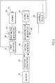
- FIG. 4 is a block configuration diagram when the control device 90 determines the target output voltage V2*.
- the control device 90 of the present embodiment determines the target output voltage V2* using the optimum efficiency voltage calculator 401 and 402, the multipliers 403 and 404, the oscillation avoidance voltage calculator 405, and the selector 406.
- the optimum efficiency voltage calculator 401 outputs the optimum efficiency voltage obtained from the torque command for the first motor generator 50 and the motor rotation speed of the first motor generator 50 to the selector 406 as the first optimum efficiency voltage V2_ m1 for the first motor generator 50. Furthermore, the optimum efficiency voltage here is the voltage that is input to the first inverter 30 to secures the output electric power required according to the operation point of the first motor generator 50 and to output the desired torque to the first motor generator 50 most efficiently. Then, the optimum efficiency voltage is obtained by a known method based on the torque command or the like for the first motor generator 50.
- the optimum efficiency voltage calculator 402 outputs the optimum efficiency voltage obtained from the torque command for the second motor generator 60 and the motor rotation speed of the second motor generator 60 to the selector 406 as the second optimum efficiency voltage V2_ m2 for the second motor generator 60. Furthermore, the optimum efficiency voltage here is the voltage that is input to the second inverter 40 to secures the output electric power required according to the operation point of the second motor generator 60 and to output the desired torque to the second motor generator 60 most efficiently. Then, the optimum efficiency voltage is obtained by a known method based on the torque command or the like for the second motor generator 60.
- the multiplier 403 calculates the required output (the required electric power P1) to the first motor generator 50 by multiplying the torque command for the first motor generator 50 by the motor rotation speed of the first motor generator 50, and outputs it to the oscillation avoidance voltage calculator 405.
- the required electric power P1 has a positive value (P1>0) when the first motor generator 50 is performed power running, and the required electric power P1 has a negative value (P1 ⁇ 0) when the first motor generator 50 is performed regenerative running.
- the multiplier 404 calculates the required output (the required electric power P2) to the second motor generator 60 by multiplying the torque command for the second motor generator 60 by the motor rotation speed of the second motor generator 60, and outputs it to the oscillation avoidance voltage calculator 405.
- the required electric power P2 has a positive value (P2>0) when the second motor generator 60 is performed power running, and the required electric power P2 has a negative value (P2 ⁇ 0) when the second motor generator 60 is performed regenerative running.
- the oscillation avoidance voltage calculator 405 receives the required electric power P1 for the first motor generator 50 and the required electric power P2 for the second motor generator 60. Then, the oscillation avoidance voltage calculator 405 calculates a lower limit voltage V 2C as a lower limit value that can avoid oscillating of the output voltage V2 when the value is higher than this, based on the required electric powers P1 and P2. In other words, the oscillation avoidance voltage calculator 405 calculates the lower limit voltage V 2C of the output voltage V2 such that the output voltage V2 of the boost converter 20 does not oscillate, based on the required electric powers P1 and P2. The calculated lower limit voltage V 2C is output to the selector 406. The details of the method of calculating the lower limit voltage V 2C will be described later.
- the selector 406 selects the largest value from the three input voltage values (select high) and outputs it. That is, the selector 406 determines the final target output voltage V2* of the boost converter 20 by selecting the highest voltage from the first optimum efficiency voltage V2_ m1 , the second optimum efficiency voltage V2_ m2 , and the lower limit voltage V 2C . Then, in a not shown control block, the control device 90 sends to the boost converter 20 a duty ratio D as a gate signal for the boost converter 20 to output the voltage corresponding to the target output voltage V2*.
- the lower limit voltage V 2C calculated in the oscillation avoidance voltage calculator 405 can be set as the target output voltage V2* without the optimum efficiency voltage calculator 401, 402 and the selector 406.
- the electric power assigned to boost converter 20 is a value obtained by adding required electric power P1 and required electric power P2 (the value is referred to as "required electric power P1+P2" below).
- the required electric power P1+P2 is positive, the output voltage V2 oscillates mainly due to the negative resistance characteristic associated with the constant power control of at least one of the first inverter 30 and the second inverter 40.
- the required electric power P1+P2 is negative, the output voltage V2 oscillates mainly due to the response delay when the electrical current flows to at least one of the first motor generator 50 and the second motor generator 60.
- the main factor causing the output voltage V2 to oscillate depends on whether the electric power required for the boost converter 20 is positive or negative.
- inverter indicates at least one of the first inverter 30 and the second inverter 40
- motor generator indicates the first motor generator 50 and the second motor generator 60.
- the required electric power P1+P2 is positive, that is, when the electric power is taken out from boost converter 20 (when power running is performed), the condition for stable supply without oscillating output voltage V2 is explained.
- V 20 in the formula indicates the value of the output voltage V2 of the boost converter
- I 10 indicates the value of the electrical current I 1 flowing through the first inverter 30
- I 20 indicates the value of the electrical current I 2 flowing through the second inverter 40
- R 0 in the formula indicates an impedance of the motor generator when the first inverter 30 and the second inverter 40 try to control the first motor generator 50 and the second motor generator 60 to constant power (required electric power P1+P2) when the output voltage V2 of the boost converter 20 is the voltage V 20 .
- I ofs will be described later with reference to FIG.5 .
- Fig. 5 is a diagram for explaining the linear approximation around an operation point when the first inverter 30 and the second inverter 40 control the first motor generator 50 and the second motor generator 60 to a constant electric power, in order to derive the above formula (1).
- the horizontal axis indicates the output voltage V2 of the boost converter 20, and the vertical axis indicates the output current (I 1 +I 2 ) of the boost converter 20.
- a curve indicated by a thick line in the figure shows a constant electric power line when the first inverter 30 and the second inverter 40 control the first motor generator 50 and the second motor generator 60 at constant power.
- the operation points of the first motor generator 50 and the second motor generator 60 are set on the constant electric power line, where the horizontal axis at V 20 and the vertical axis at I10+I20.
- the above formula (1) is derived by linear approximation around the operation point (V 20 , I 10 +I 20 ) (see the dotted line in the figure). Further, as indicated by the dotted line in the figure, I ofs in the formula (1) is expressed by an intercept of a straight-line when linearly approximated at the operation point (V 20 , I 10 +I 20 ). Further, R0, indicating the impedance of the motor generator, is set to a positive value when required electric power P1+P2 is positive and is set to a negative value when required electric power P1+P2 is negative.
- L in formula (2) indicates the inductance [H] of the reactor 3
- C indicates the capacity [F] of the capacitor 7
- R indicates the circuit resistance [ ⁇ ] of the boost converter 20 when the switching element 4b is turned ON.
- the formula (5) defines the conditions for stable supply of output voltage V2 of boost converter 20. According to the formula (5), it can be seen that the output voltage V2 must be increased as the required electric power P1+P2 increases, in order not to oscillate the output voltage V2 of the boost converter 20 when the required electric power P1+P2 to the boost converter 20 is positive.
- the lower limit voltage V2c of the output voltage V2 of the boost converter 20 is set to satisfy the formula (5) in order not to oscillate the output voltage V2 of the boost converter 20.
- the lower limit voltage V2 C may be calculated in consideration of at least one of the response characteristics of the electrical current
- one of the response characteristics of the electrical current is the response characteristic of the electrical current I1 flows to the first motor generator 50 according to the required electric power P1
- the other of the response characteristic of the electrical current is the response characteristic of the electrical current 12 flows to the second motor generator 60 according to the required electric power P2, when the output voltage V2 of the boost converter 20 is applied to the second motor generator 60.
- the lower limit voltage V2c at which the output voltage V2 does not oscillate can be calculated more accurately.
- the value of the lower limit voltage V2 C shown on the right side of the formula (5) is calculated without considering the response characteristic of the electrical current described above, and is therefore a value calculated under the most severe conditions. For this reason, the value of the lower limit voltage V2 C shown on the right side of the formula (5) is a value larger than that when calculated in consideration of the response characteristic of the electrical current. Therefore, in the case where the suppression of oscillation is the main purpose, it is not always necessary to consider the response characteristic of the electrical current described above when calculating the lower limit voltage V2 C . By setting the lower limit voltage V2c so as to satisfy the formula (5), it is possible to reliably prevent the output voltage V2 of the boost converter 20 from oscillating.
- the transfer characteristic from the input voltage V1 to the output voltage V2 of the boost converter 20 is calculated, it is expressed by the following formula (7).
- the response characteristic of the electrical current is considered when the electrical current 12 flows to the second motor generator 60 according to the required electric power P2 when the output voltage V2 of the boost converter 20 is applied to the input section (DC section).
- This current response characteristic is represented by the second-order delay system of the following formula (6).
- ⁇ 2 in the formula (6) indicates the damping coefficient of the second-order delay system.
- ⁇ 2 indicates the natural frequency when the natural oscillation frequency of the second-order delay system is f2, and is a value determined by the operation point of the second motor generator 60. Furthermore, since the required electric power P1+P2 is negative, P0 ⁇ 0 is set.
- V 2 R 0 s 2 + 2 ⁇ 2 ⁇ 2 s + ⁇ 2 2 DV 1 ⁇ R 0 Ls + R ⁇ 2 2 I ofs R 0 LCs 4 + R 0 C 2 ⁇ 2 ⁇ 2 L + R s 3 + R 0 LC ⁇ 2 2 + 2 ⁇ 2 ⁇ 2 RC + D 2 s 2 + ⁇ 2 ⁇ R 0 CR ⁇ 2 + 2 ⁇ 2 D 2 ⁇ L ⁇ 2 ) s + ⁇ 2 D 2 R 0 ⁇ R
- the conditions for the output voltage V2 are calculated by arranging the obtained conditions for R 0 with the output voltage V2 of the boost converter and the required electric power P1+P2, by using the above formula (4). Then, by setting the output voltage V2 of the boost converter 20 to the lower limit voltage V2c or more so as to satisfy the condition, it is possible to suppress the output voltage V2 from oscillating.
- the output voltage V2 of the boost converter 20 becomes easier to oscillate by interference between them. Therefore, in the present embodiment, the lower limit voltage V2c of the output voltage V2 is set to be higher as the resonance frequency of the boost converter 20 is closer to the oscillation frequency of the motor generator. As a result, since the output voltage of the boost converter 20 is increased and the stability can be improved, the oscillation of the output voltage V2 can be further suppressed.
- FIG. 6 is a flowchart showing a target output voltage V2* setting process of the boost converter 20 executed by the control device 90 of the present embodiment.
- the flowchart described below is programmed in the control device 90 so as to be constantly executed at regular intervals while the vehicle system is activated.
- step S1 the control device 90 acquires the torque command for each of the first motor generator 50 and the second motor generator 60, and acquires the rotation speed for each of the first motor generator 50 and the second motor generator 60.
- step S2 the control device 90 acquires the electrical response characteristic parameter values of the first motor generator 50 and the second motor generator 60.
- An electrical response characteristic parameter value is an index showing the current response characteristic of the motor generator and includes information on the oscillation frequency of the motor generator.
- the electrical response characteristic parameter value in this embodiment is acquired from a map in which the relationship between the operation point and the current response characteristic is stored according to the operation point of the motor generator determined from the torque command value acquired in step S1.
- step S3 the control device 90 sets the lower limit voltage V2c for stable supply of the output voltage V2 of the boost converter 20 without oscillating.
- the method of setting the lower limit voltage V2c in the present embodiment differs depending on the following two conditions.
- the two conditions are (a) a case where an unknown parameter is included in the response characteristics of the electrical current flowing into the inverter, and (b) a case where the response characteristics of the electrical current flowing into the inverter are known.
- the case where the response characteristic of the electrical current is unknown is a case where the response characteristic cannot be described by the formula (6).
- the case where the response characteristic of the electrical current is known is a case where the response characteristic can be described by the formula (6).
- FIG. 7 is a flowchart showing the lower limit voltage V2 C setting process executed in step S3 under the condition (a).
- step S301 the control device 90 calculates the lower limit voltage V2 C0 based on the right side of the above formula (5).
- the lower limit voltage V 2C is calculated so that the output voltage V2 does not oscillate without considering the response characteristic of the electrical current flowing into the inverter.
- the lower limit voltage V2 C0 increases as the required output P1+P2 to the boost converter 20 increases.
- the larger the output of the motor generator the easier the output voltage of boost converter 20 will be to oscillate. Therefore, by increasing the output voltage V2 as the output of the motor generator, that is, the required output P1+P2 increases, it is possible to suppress the increase of the oscillate with respect to the output voltage V2.
- step S302 the control device 90 changes the value of the lower limit voltage V2 C0 in consideration of the current-response delay of the motor generator.
- the current-response delay of the motor generator affects the stability of the boost converter system including the boost converter 20, the motor generator and the inverter. Therefore, the stability and efficiency of the boost converter system can be made compatible by changing the value of the lower limit voltage V2 according to the current-response delay of the motor generator.
- the control device 90 calculates the lower limit voltage V2 C1 that becomes larger as the current-response delay becomes smaller with respect to the lower limit voltage V2 C0 .
- the required electric power P1+P2 is positive, the stability of the boost converter system decreases mainly due to the negative resistance characteristic by the constant power control of the inverter.
- the influence of the negative resistance characteristic is more pronounced as the current-response delay of the motor generator is smaller. Therefore, by setting the lower limit voltage V2 to be larger as the current-response delay is smaller, it is possible to suppress the output voltage V2 from oscillating.
- the lower limit voltage V2 C1 is calculated such that the larger the current-response delay, the larger the lower limit voltage V2 C0 .
- the required electric power P1+P2 is negative, the stability of the boost converter system decreases as the current-response delay of the motor generator increases. Therefore, it is possible to suppress the output voltage V2 from oscillating by setting the lower limit voltage V2 to be larger as the current-response delay is larger.
- required electric power P1+P2 is positive.
- the lower limit voltage V2 C1 is calculated by adding a lower limit voltage corrected value A as shown in FIG. 8 to the lower limit voltage V2 C0 calculated in step S301.
- FIG. 8 is a diagram showing the relationship between the lower limit voltage corrected value A and the oscillation frequency of the motor generator when the required electric power P1+P2 is positive.
- the lower limit voltage corrected value A is a negative value, and as the oscillation frequency of the motor generator becomes smaller, the lower limit voltage corrected value A has a large value on the negative side.
- the current-response delay becomes larger as the oscillation frequency of the motor generator becomes smaller. That is, the lower limit voltage V2 C1 when the required electric power P1+P2 is set to a value smaller than the lower limit voltage V2 C0 as the current-response delay becomes larger.
- step S303 the control device 90 calculates the resonance frequency fc of the boost converter 20.
- L in the formula (8) is the inductance [H] of the reactor 3
- C is the capacity [F] of the capacitor 7
- D is the duty ratio for turning on the switching element 4a.
- the reciprocal of D is the boost ratio of boost converter 20.
- the control device 90 compares the resonance frequency fc of the boost converter 20 obtained at step S303 with the oscillation frequency of the motor generator obtained at step S2 of FIG. 6 , and the control device 90 determines whether the absolute value of the difference (hereinafter referred to as "frequency difference") is smaller than the predetermined value A.
- the predetermined value A is determined in advance by experiments or the like from the viewpoint of whether the lower limit voltage V2c calculated based on the comparison result with the predetermined value A can substantially suppress the oscillation of the output voltage V2.
- the predetermined value A in this embodiment is set to 50 Hz, for example.
- step S302 When the frequency difference is greater than or equal to the predetermined value A, the lower limit voltage V2 C1 calculated in step S302 is set as the lower limit voltage V2 C , the process of step S3 is ended, and the process of step S4 is performed (see FIG. 6 ).
- step S305 the lower limit voltage V2 C1 is increased based on the frequency difference acquired in step S304.
- the control device 90 calculates the lower limit voltage V2 C that has a larger value as the frequency difference is smaller with respect to the lower limit voltage V2 C1 .
- the lower limit voltage V2 C calculated in this step is calculated by adding the lower limit voltage corrected value B as shown in FIG. 9 to the lower limit voltage V2 C1 calculated in step S302.
- the lower limit voltage V2 is corrected by the lower limit voltage corrected value B calculated based on the frequency difference.
- FIG. 9 is a diagram showing the relationship between the lower limit voltage corrected value B and the frequency difference.
- the lower limit voltage corrected value B shows a positive value in a region where the frequency difference is smaller than the predetermined value A, and becomes larger as the frequency difference decreases toward 0. That is, in this step, the lower limit voltage V2 C1 calculated in step S302 is added with the lower limit voltage corrected value B that is larger as the frequency difference is smaller, whereby the lower limit voltage V2 C is calculated.
- the frequency difference becomes smaller, and it may be necessary to add the voltage. More specifically, when the lower limit voltage V2 C becomes a larger value by adding the lower limit voltage corrected value B and the duty ratio D is set to a smaller value in order to increase the output voltage V2, and accordingly, the frequency difference between the resonance frequency fc and the oscillation frequency of the motor generator may become further smaller. In this case, it is necessary to add the lower limit voltage corrected value B corresponding to the smaller frequency difference (see FIG. 9 ) and reset the lower limit voltage V2 C to a larger value.
- the process in step S305 may be performed as follows. That is, when the frequency difference after adding the lower limit voltage corrected value B (see FIG. 9 ) calculated based on the frequency difference acquired in step S304 is smaller than the value before the addition, the process corresponding the following two conditions may be performed.
- the two conditions are that (c) the frequency difference becomes smaller and the resonance frequency f C of the boost converter 20 is larger than the oscillation frequency of the motor generator (the resonance frequency fc > the oscillation frequency), and (d) the frequency difference becomes smaller and the resonance frequency fc of the boost converter 20 is smaller than the oscillation frequency of the motor generator (the resonance frequency fc ⁇ the oscillation frequency).
- the control device 90 adds the lower limit voltage corrected value B (see FIG. 9 ) when the frequency difference is zero to the lower limit voltage V2 C1 calculated in step S302.
- the control device 90 adds a value to the lower limit voltage V2 C1 calculated in step S302, the value obtained by adding the lower limit voltage corrected value B based on the frequency difference before adding the lower limit voltage corrected value B and the lower limit voltage corrected value B based on the frequency difference after adding the lower limit voltage corrected value B.
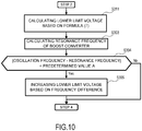
- FIG. 10 is a flowchart showing the lower limit voltage V2 C setting process executed in step S3 in the case of the condition (b).
- the same steps as those in the flowchart shown in FIG. 7 are designated by the same step numbers, and description thereof will be omitted.
- step S311 the control device 90 calculates the lower limit voltage V2 C0 based on the above formula (6) and formula (7). Specifically, when the response characteristic of the electrical current flowing into the inverter when the output voltage V2 of the boost converter 20 is applied to the inverter can be described by the formula (6), the control device 90 calculates the lower limit voltage V2 C of the output voltage V2 such that the transfer characteristic (the formula (7)) from the input voltage V1 to the output voltage V2 becomes stable.
- control device 90 can also acquires, in advance, a map associated the damping coefficient ⁇ 2 indicated by the formula (6), the natural oscillation frequency f2, the input voltage V1 of the boost converter 20, and the required electric power P1+P2 to the boost converter 20, with the lower limit voltage V2c at which the output voltage V2 becomes stable. Then, the control device 90 can calculate the lower limit voltage V2 C by referring to above map according to the operation point of the motor generator.
- control device 90 executes the same processing as the processing having the same step number in FIG. 6 and sets lower limit voltage V2 C .
- the lower limit voltage V2 C in which the current response characteristic is taken into consideration can be calculated immediately.
- the lower limit voltage V2 C calculated by the flow shown in FIG. 7 and FIG. 10 has the following values. That is, the lower limit voltage V2 C has a larger value as the required electric power P1+P2 to the boost converter 20 becomes larger. Also, when the required electric power P1+P2 is positive, the lower limit voltage V2c becomes smaller as the response delay of the electrical current flowing into the inverter becomes larger. Also, when the required electric power P1+P2 is negative, the lower limit voltage V2 C becomes larger as the response delay of the electrical current flowing into the inverter becomes larger. Further, the lower limit voltage V2 C has a larger value as the difference (the frequency difference) between the resonance frequency fc of the boost converter 20 and the oscillation frequency of the motor generator is smaller.
- a value obtained by adding, for example, a 10% margin to the lower limit voltage V2 C may be set as the final lower limit voltage V2 C in consideration of variations in the calculated value and the detected value accompanying the calculation.
- the controller 90 subsequently executes the process of step S4 shown in FIG. 6 .
- step S4 shown in FIG. 6 .
- step S4 the control device 90 calculates the first optimum efficiency voltage V2_ m1 and the second optimum efficiency voltage V2_ m2 . More specifically, the control device 90 calculates the first optimum efficiency voltage V2_ m1 for the first motor generator 50 from the torque command for the first motor generator 50 and the motor rotation speed of the first motor generator 50, and the controller 90 calculates the second optimum efficiency voltage V2_ m2 for the second motor generator 60 from the torque command for the second motor generator 60 and the motor rotation speed of the second motor generator 60.
- step S5 the control device 90 selects the largest voltage value from the three voltage values of the lower limit voltage V2 C obtained in step S3, the first optimum efficiency voltage V2_ m1 obtained in step S4, and the second optimum efficiency voltage V2_ m2 , and the control device 90 sets the selected voltage value to the target output voltage V2* (the target output voltage command value V2*). This allows the boost converter 20 to output the output voltage V2 satisfying the required electric power P1+P2 and suppressing the oscillation.
- FIG. 11 is a time chart explaining the behavior of the output voltage V2 when the control method of the boost converter 20 of this embodiment is applied.
- FIG. 11A shows the output voltage of the boost converter 20
- FIG. 11B shows the required electric power P1+P2 assigned to the boost converter 20.
- the horizontal axis represents time.
- the required electric power P1+P2 shows a constant positive value, and the vehicle is in power running.
- the target output voltage to the boost converter 20 is calculated according to the required electric power P1+P2
- the target output voltage shown by the one-dot chain line in FIG. 11A is calculated.
- the actual output voltage output according to the target output voltage considering only the efficiency becomes oscillation tendency as shown by the dotted line in the figure.
- the target output voltage (the first optimum efficiency voltage V2_ m1 and the second optimum efficiency voltage V2_ m2 ) considering only the efficiency is calculated as in the conventional case, and calculated the lower limit voltage V2 C such that the actual output voltage does not oscillate. Then, the highest voltage value is set as the target output voltage V2* by the select-high of these voltage values.
- the lower limit voltage V2 C calculated by the control method of the boost converter 20 according to the present embodiment is larger than the target output voltage calculated by considering only the efficiency as in the conventional case.
- the lower limit voltage V2c is selected by the select-high, and the lower limit voltage V2c is set as the target output voltage V2*.
- the control method of the boost converter 20 is the control method of the boost converter 20 comprises boosting the voltage input from the electric power supply and suppling the boosted voltage to the load-side.
- the control method of the boost converter 20 comprises securing the output electric power (the required electric power P1+P2) required according to the operation point of the motor (the first motor generator 50 and the second motor generator 60) connected to the load-side, calculating the lower limit voltage value (the lower limit voltage V2 C ) at which the output voltage V2 of the boost converter 20 does not oscillate, setting the target output voltage V2* of the boost converter 20 to a value equal to or higher than the lower limit voltage V2 C , and controlling the boost converter so as to output a voltage according to the target output voltage.
- This can prevent the output voltage V2 of the boost converter 20 from becoming an oscillation tendency. As a result, it is possible to prevent the occurrence of overvoltage, overcurrent, and torque oscillation of the motor generator due to the output voltage V2 oscillating.
- the lower limit voltage V2 C is set to a larger value as the output electric power (the request output P1+P2) of the motor generator is larger. For this reason, the output voltage V2 is set to a larger value as the output P1+P2 is larger, so that it is possible to prevent the oscillation from increasing with respect to the output voltage V2. As a result, it is possible to prevent the occurrence of overvoltage, overcurrent, and torque oscillation of the motor generator due to the output voltage V2 oscillating.
- the lower limit voltage V2 C is changed according to the value of the current-response delay of the motor generator. This makes it possible to achieve both stability and efficiency of the boost converter system.
- the lower limit voltage V2 C is set to a larger value as the current-response delay of the motor generator is smaller.
- the influence of the negative resistance characteristic due to the constant power control of the inverter can be reduced, so that the output voltage V2 can be suppressed from oscillating.
- the lower limit voltage V2 C is set to a larger value as the current-response delay of the motor generator is larger. This can prevent the output voltage V2 from oscillating.
- the lower limit voltage V2 is corrected by adding a correction value (the lower limit voltage corrected value B) that is calculated to become larger as the frequency difference between the resonance frequency of the boost converter 20 and the oscillation frequency of the motor generator becomes smaller.
- a correction value (the lower limit voltage corrected value B) that is calculated to become larger as the frequency difference between the resonance frequency of the boost converter 20 and the oscillation frequency of the motor generator becomes smaller.
- the correction value (the lower limit voltage corrected value B) is set as a value calculated when the frequency difference is 0, in the case where, after corrected, the frequency difference becomes smaller than the frequency difference before correction and the resonance frequency fc of the boost converter 20 is larger than the oscillation frequency of the motor generator.
- the calculation time can be shortened and the target output voltage V2* at which the output voltage does not oscillate can be calculated faster.
- the correction value (the lower limit voltage corrected value B) is set as a value adding a correction value (the lower limit voltage corrected value B) calculated based on the frequency difference before correction and a correction value (the lower limit voltage corrected value B) calculated based on the frequency difference after correction, in the case where, after corrected, the frequency difference is smaller than the frequency difference before correction and the resonance frequency fc of boost converter 20 is smaller than the oscillation frequency of the motor generator.
- the calculation time can be shortened and the target output voltage V2* where the output voltage does not oscillate can be calculated faster.
- control method of the boost converter 20 of one embodiment comprises securing the output electric power (the required electric power PI, P2) required according to the operation point of the motor generator, calculating the optimum efficiency voltage value (the first optimum efficiency voltage V2_ m1 and second optimum efficiency voltage V2_ m2 ) for driving the motor generator most efficiently, and setting the larger voltage value of the lower limit voltage V2 C and the optimum efficiency voltage value to the target output voltage V2*.
- the optimum efficiency voltage value is larger than the lower limit voltage V2c, it is possible to suppress oscillation and output the output voltage V2 that can most efficiently drive the motor generator to the boost converter 20.
- the vehicle to which the control method of the boost converter 20 of the present embodiment is applied is the series system hybrid vehicle, it is not necessarily limited to this case.
- the control method of the boost converter 20 according to the present invention can be appropriately applied to any boost converter system in which at least one set of an inverter and a motor are connected to the load-side of the boost converter 20.
Landscapes
- Engineering & Computer Science (AREA)
- Power Engineering (AREA)
- Electric Propulsion And Braking For Vehicles (AREA)
- Dc-Dc Converters (AREA)
- Rotational Drive Of Disk (AREA)
Abstract
Description
- The present invention relates to a boost converter control method and a control apparatus.
-
JP2009-225634A - Here, in the case of that the motor is driven through the boost converter, when the motor operates in power running, there is a case where the boosted voltage oscillates due to the negative resistance characteristic associated with the constant power control of the inverter. Further, when the motor operates in a regenerative running, there is a case where the voltage after boosting oscillates due to a response delay of the electrical current flowing into the inverter with respect to the boosted voltage.
- However, in the technique disclosed in
JP2009-225634A - An object of the present invention is to provide a technique for suppressing the output voltage of the boost converter from oscillating regardless of the operating state of the motor (the power running, the regenerative running).
- A boost converter control method in one aspect of the present invention is the control method of the boost converter that boosts a voltage input from a power supply and supplies a boosted voltage to a load-side. The control method of the boost converter is securing an output electric power required according to an operation point of a motor connected to the load-side, calculating a lower limit voltage value at which the output voltage of the boost converter does not oscillate, setting a target output voltage of the boost converter to a value equal to or higher than the lower limit voltage, and controlling the boost converter so as to output a voltage according to the target output voltage.
- Embodiments of the present invention will be described in detail below with the accompanying drawings.
-
-
FIG. 1 is a system configuration diagram of a hybrid vehicle to which a control apparatus of a boost converter according to the present invention is applied. -
FIG. 2 is a system configuration diagram describing each configuration shown inFIG. 1 in more detail. -
FIG. 3 is a circuit configuration diagram for explaining a circuit configuration of a boost converter. -
FIG. 4 is a block configuration diagram used in determining the target output voltage V2*. -
FIG. 5 is a diagram for explaining the linear approximation of a motor generator around an operation point. -
FIG. 6 is a flowchart showing a setting process of the target output voltage V2*. -
FIG. 7 is a flowchart showing a setting process of the lower limit voltage V2c in the case of the condition (a). -
FIG. 8 is a diagram showing the relationship between the corrected lower limit voltage value A and the oscillation frequency of the motor generator. -
FIG. 9 is a diagram showing the relationship between the corrected lower limit voltage value B and frequency difference. -
FIG. 10 is a flowchart showing a setting process of the lower limit voltage V2c in the case of the condition (b). -
FIG. 11 is a diagram for explaining the effect of the control method of the boost converter in one embodiment. -
FIG. 1 is a system configuration diagram of a hybrid vehicle to which a control apparatus of a boost converter according to the present invention is applied.FIG. 1 shows a configuration example in which the control apparatus of the boost converter is applied to a hybrid vehicle equipped with two motor generators. As shown in the figure, the hybrid vehicle of the present embodiment includes abattery 10, aboost converter 20, afirst inverter 30, asecond inverter 40, afirst motor generator 50, asecond motor generator 60, anengine 70, arotation speed detector output shaft 80, and acontrol device 90. -
FIG. 2 is a system configuration diagram describing each configuration shown inFIG. 1 in more detail. Details of each configuration will be described with reference toFIG. 2 . - The
battery 10 is a chargeable/dischargeable secondary battery, for example, a lithium ion secondary battery. - The
boost converter 20 is an electric power conversion device that boosts an inputted voltage and outputs it. In theboost converter 20 of the present embodiment, thebattery 10 as a power supply is connected to the primary side (input-side), and thefirst inverter 30 and thesecond inverter 40 are connected in parallel to the secondary side (output-side, load-side). Details of the configuration of theboost converter 20 will be described with reference toFIG. 3 . -
FIG. 3 is a circuit configuration diagram for explaining a circuit configuration of aboost converter 20. Theboost converter 20 mainly includes acapacitor 1, a reactor (inductance) 3, and switchingelements boost converter 20 boosts the input voltage V1 of the direct current input from thebattery 10, and outputs the output voltage V2 after boosted. - The
capacitor 1 rectifies the input voltage V1 by absorbing the pulsating flow (voltage ripple) generated in the input voltage V1 due to the switching of theswitching elements - The
voltage sensor 2 is attached in thecapacitor 1, detects the input voltage V1 of theboost converter 20, that is, the voltage of thecapacitor 1, and sends the detected voltage value to thecontrol device 90. - The
reactor 3 accumulates electric energy from thebattery 10 when theswitching element 4a is turned ON and theswitching element 4b is turned OFF, and discharges the accumulated electric energy when theswitching element 4a is turned OFF and theswitching element 4b is turned ON. As a result, theboost converter 20 can boost the DC voltage from thebattery 10. The voltage value after boosted (voltage value of the output voltage V2) can be arbitrarily adjusted by changing the ratio (duty ratio D) of the period in which theswitching element 4a is turned ON. Thereactor 3 also has a function of suppressing the voltage ripple generated due to the switching of theswitching elements - The
switching elements diodes switching elements - The
current sensor 6 detects the electrical current through thereactor 3 and sends the detected current value to thecontrol device 90. In other words, thecurrent sensor 6 can detect the direct electrical current flowing out of thebattery 10 or flowing into thebattery 10, through theboost converter 20. - The
capacitor 7 rectifies the output voltage V2 by absorbing the pulsating flow (voltage ripple) generated in the output voltage V2 due to the switching of theswitching elements - The
voltage sensor 8 is attached in thecapacitor 7, detects the output voltage V2 of theboost converter 20, that is, the voltage of thecapacitor 7, and sends the detected voltage value to thecontrol device 90. Hereinafter, returning toFIG. 2 , the description will be continued. - The
first inverter 30 and thesecond inverter 40 are three-phase inverters that can output three-phase AC power. - The
first inverter 30 converts DC power (the output voltage V2) input from theboost converter 20 into the three-phase first AC power, and supplies it to thefirst motor generator 50. Further, thefirst inverter 30 converts the three-phase AC power generated by thefirst motor generator 50 into DC power and charges thebattery 10 thorough theboost converter 20, or supplies the DC power to thesecond inverter 40. - The
second inverter 40 converts the DC power input from theboost converter 20 into the three-phase second AC power, and supplies it to thesecond motor generator 60. Further, thesecond inverter 40 converts the three-phase second AC power (the regenerative electric power) generated by thesecond motor generator 60 into DC power, and charges thebattery 10 through theboost converter 20. - The
current sensor 9a is attached to the electric power line connecting thefirst inverter 30 and thefirst motor generator 50, detects the electrical current through the electric power line, and sends the detected current value to thecontrol device 90. Further, thecurrent sensor 9b is attached to the electric power line connecting thesecond inverter 40 and thesecond motor generator 60, detects the electrical current through the electric power line, and sends the detected current value to thecontrol device 90. Thecurrent sensors current sensors - In this specification, when simply described as "inverter", at least one of the
first inverter 30 and thesecond inverter 40 is indicated. Further, in the present specification, when simply described as a motor generator or a motor, at least one of thefirst motor generator 50 and thesecond motor generator 60 is indicated. - The
first motor generator 50 of this embodiment is, for example, an electric power generator. Thefirst motor generator 50 rotates by the driving force from theengine 70 to generate electric power. Further, at the time of starting theengine 70, thefirst motor generator 50 performs cranking theengine 70 using the driving force from thefirst motor generator 50, and also performs motoring for consuming electric power by rotating theengine 70 by power running using the driving force of thefirst motor generator 50. - The
second motor generator 60 of this embodiment is, for example, a drive motor that functions as a drive source for the vehicle. Thesecond motor generator 60 generates a driving force by the AC power supplied from thesecond inverter 40 and transmits the driving force to theoutput shaft 80. Further, thesecond motor generator 60 recovers the kinetic energy of the vehicle as electric energy by generating regenerative driving force when being driven by the driving wheels and rotated such as during deceleration or during coast running. - That is, the control apparatus of the
boost converter 20 according to the present embodiment is applied to a so-called series type hybrid vehicle equipped with a first motor generator 50 (an electric power generator) for power generation and a second motor generator 60 (a drive motor) for driving. - The
engine 70 is connected to the rotating shaft of thefirst motor generator 50 through a gear not shown in FIGs, and transmits the driving force for thefirst motor generator 50 to generate electric power, to thefirst motor generator 50. In addition, the vehicle to which the control apparatus of theboost converter 20 of the present embodiment is applied is the series type. Therefore, in principle, theengine 70 in this embodiment is used only as a drive source for rotationally driving thefirst motor generator 50. However, a known torque transmission device may be arranged between theengine 70 and theoutput shaft 80 in order to transmit the output torque of theengine 70 to theoutput shaft 80. - The
rotation speed detectors rotation speed detectors first motor generator 50 and thesecond motor generator 60, respectively, and detect the rotation angle or the rotation speed of the each rotors included in thefirst motor generator 50 and thesecond motor generator 60, and output it to thecontrol device 90. Therotation speed detector 71 is attached to theengine 70, detects a rotation angle or a rotation speed of a crankshaft included in theengine 70, and outputs it to thecontrol device 90. - The
control device 90 controls the driving of theboost converter 20, thefirst inverter 30, thesecond inverter 40, thefirst motor generator 50, thesecond motor generator 60, and theengine 70. Thecontrol device 90 is composed of one or a plurality of controllers. The controller is, for example, composed of a central processing unit (CPU), a read only memory (ROM), a random-access memory (RAM), and an input/output interface (I/O interface). - More specifically, the
control device 90 creates a switching pattern according to the torque command for thefirst motor generator 50, the motor rotation speed of the first motor generator 50 (the detection value of the rotation speed detector 51), the input/output current value (the detection value of thecurrent sensor 9a), and the input voltage (the detection value of the voltage sensor 8). Then, thecontrol device 90 sends the switching pattern as a gate signal to thefirst inverter 30. Further, thecontrol device 90 creates a switching pattern according to the torque command for thesecond motor generator 60, the motor rotation speed of the second motor generator 60 (the detection value of the rotation speed detector 61), the input/output current value (the detection value of thecurrent sensor 9b), and the input voltage (the detection value of the voltage sensor 8). Then, thecontrol device 90 sends the switching pattern as a gate signal to thesecond inverter 40. In addition, the torque command here, is a command value (a torque request value) for causing the motor to output a desired torque (a request torque), and is calculated, for example, based on the accelerator opening degree or the like. - Further, the
control device 90 calculates the input voltage required for thefirst motor generator 50 according to the torque command for thefirst motor generator 50 and the motor rotation speed of thefirst motor generator 50. Further, thecontrol device 90 calculates the input voltage required for thesecond motor generator 60 according to the torque command for thesecond motor generator 60 and the motor rotation speed of thesecond motor generator 60. Then, thecontrol device 90 sets the voltage value determined based on each calculated input voltage as the target output voltage V2* of theboost converter 20. Then, thecontrol device 90 creates a switching pattern (duty ratio D) for outputting the target output voltage V2* and sends the duty ratio D to theboost converter 20 as a gate signal. - Next, a method of setting the target output voltage V2* in this embodiment will be described with reference to
FIG. 4 . -
FIG. 4 is a block configuration diagram when thecontrol device 90 determines the target output voltage V2*. Thecontrol device 90 of the present embodiment determines the target output voltage V2* using the optimumefficiency voltage calculator multipliers avoidance voltage calculator 405, and theselector 406. - The optimum
efficiency voltage calculator 401 outputs the optimum efficiency voltage obtained from the torque command for thefirst motor generator 50 and the motor rotation speed of thefirst motor generator 50 to theselector 406 as the first optimum efficiency voltage V2_m1 for thefirst motor generator 50. Furthermore, the optimum efficiency voltage here is the voltage that is input to thefirst inverter 30 to secures the output electric power required according to the operation point of thefirst motor generator 50 and to output the desired torque to thefirst motor generator 50 most efficiently. Then, the optimum efficiency voltage is obtained by a known method based on the torque command or the like for thefirst motor generator 50. - The optimum
efficiency voltage calculator 402 outputs the optimum efficiency voltage obtained from the torque command for thesecond motor generator 60 and the motor rotation speed of thesecond motor generator 60 to theselector 406 as the second optimum efficiency voltage V2_m2 for thesecond motor generator 60. Furthermore, the optimum efficiency voltage here is the voltage that is input to thesecond inverter 40 to secures the output electric power required according to the operation point of thesecond motor generator 60 and to output the desired torque to thesecond motor generator 60 most efficiently. Then, the optimum efficiency voltage is obtained by a known method based on the torque command or the like for thesecond motor generator 60. - The
multiplier 403 calculates the required output (the required electric power P1) to thefirst motor generator 50 by multiplying the torque command for thefirst motor generator 50 by the motor rotation speed of thefirst motor generator 50, and outputs it to the oscillationavoidance voltage calculator 405. In addition, the required electric power P1 has a positive value (P1>0) when thefirst motor generator 50 is performed power running, and the required electric power P1 has a negative value (P1<0) when thefirst motor generator 50 is performed regenerative running. - The
multiplier 404 calculates the required output (the required electric power P2) to thesecond motor generator 60 by multiplying the torque command for thesecond motor generator 60 by the motor rotation speed of thesecond motor generator 60, and outputs it to the oscillationavoidance voltage calculator 405. In addition, the required electric power P2 has a positive value (P2>0) when thesecond motor generator 60 is performed power running, and the required electric power P2 has a negative value (P2<0) when thesecond motor generator 60 is performed regenerative running. - The oscillation
avoidance voltage calculator 405 receives the required electric power P1 for thefirst motor generator 50 and the required electric power P2 for thesecond motor generator 60. Then, the oscillationavoidance voltage calculator 405 calculates a lower limit voltage V2C as a lower limit value that can avoid oscillating of the output voltage V2 when the value is higher than this, based on the required electric powers P1 and P2. In other words, the oscillationavoidance voltage calculator 405 calculates the lower limit voltage V2C of the output voltage V2 such that the output voltage V2 of theboost converter 20 does not oscillate, based on the required electric powers P1 and P2. The calculated lower limit voltage V2C is output to theselector 406. The details of the method of calculating the lower limit voltage V2C will be described later. - The
selector 406 selects the largest value from the three input voltage values (select high) and outputs it. That is, theselector 406 determines the final target output voltage V2* of theboost converter 20 by selecting the highest voltage from the first optimum efficiency voltage V2_m1, the second optimum efficiency voltage V2_m2, and the lower limit voltage V2C. Then, in a not shown control block, thecontrol device 90 sends to the boost converter 20 a duty ratio D as a gate signal for theboost converter 20 to output the voltage corresponding to the target output voltage V2*. In addition, when the efficiency of the motor generator is not considered, the lower limit voltage V2C calculated in the oscillationavoidance voltage calculator 405 can be set as the target output voltage V2* without the optimumefficiency voltage calculator selector 406. - Here, the principle that output voltage V2 oscillates in
boost converter 20 will be described. - As a general rule, the electric power assigned to boost
converter 20 is a value obtained by adding required electric power P1 and required electric power P2 (the value is referred to as "required electric power P1+P2" below). When the required electric power P1+P2 is positive, the output voltage V2 oscillates mainly due to the negative resistance characteristic associated with the constant power control of at least one of thefirst inverter 30 and thesecond inverter 40. On the other hand, when the required electric power P1+P2 is negative, the output voltage V2 oscillates mainly due to the response delay when the electrical current flows to at least one of thefirst motor generator 50 and thesecond motor generator 60. That is, the main factor causing the output voltage V2 to oscillate depends on whether the electric power required for theboost converter 20 is positive or negative. In the following, when simply referred to as "inverter", "inverter" indicates at least one of thefirst inverter 30 and thesecond inverter 40, and when simply referred to as "motor generator", the "motor generator" indicates thefirst motor generator 50 and thesecond motor generator 60. - At first, the required electric power P1+P2 is positive, that is, when the electric power is taken out from boost converter 20 (when power running is performed), the condition for stable supply without oscillating output voltage V2 is explained.
- The relationship between the output electric power V2 of the
boost converter 20 and the output current (I1+I2) of theboost converter 20 is expressed by the following formula (1). Where, V20 in the formula indicates the value of the output voltage V2 of theboost converter 20, I10 indicates the value of the electrical current I1 flowing through thefirst inverter 30, and I20 indicates the value of the electrical current I2 flowing through thesecond inverter 40. Further, R0 in the formula indicates an impedance of the motor generator when thefirst inverter 30 and thesecond inverter 40 try to control thefirst motor generator 50 and thesecond motor generator 60 to constant power (required electric power P1+P2) when the output voltage V2 of theboost converter 20 is the voltage V20. Iofs will be described later with reference toFIG.5 .
[Expression 1]
-
Fig. 5 is a diagram for explaining the linear approximation around an operation point when thefirst inverter 30 and thesecond inverter 40 control thefirst motor generator 50 and thesecond motor generator 60 to a constant electric power, in order to derive the above formula (1). The horizontal axis indicates the output voltage V2 of theboost converter 20, and the vertical axis indicates the output current (I1+I2) of theboost converter 20. Further, a curve indicated by a thick line in the figure shows a constant electric power line when thefirst inverter 30 and thesecond inverter 40 control thefirst motor generator 50 and thesecond motor generator 60 at constant power. The operation points of thefirst motor generator 50 and thesecond motor generator 60 are set on the constant electric power line, where the horizontal axis at V20 and the vertical axis at I10+I20. - As shown in the figure, the above formula (1) is derived by linear approximation around the operation point (V20, I10+I20) (see the dotted line in the figure). Further, as indicated by the dotted line in the figure, Iofs in the formula (1) is expressed by an intercept of a straight-line when linearly approximated at the operation point (V20, I10+I20). Further, R0, indicating the impedance of the motor generator, is set to a positive value when required electric power P1+P2 is positive and is set to a negative value when required electric power P1+P2 is negative. In the illustrated state, the transfer characteristic of the
boost converter 20 from the input voltage V1 to the output voltage V2 is expressed by the following formula (2).
[Expression 2]
- Where, L in formula (2) indicates the inductance [H] of the
reactor 3, C indicates the capacity [F] of thecapacitor 7, and R indicates the circuit resistance [Ω] of theboost converter 20 when the switchingelement 4b is turned ON. - As described above, when the power (required electric power P1+P2) assigned to the
boost converter 20 is positive, Ro>0 is set. Therefore, the condition of R0 for stably supplying the output voltage V2 of theboost converter 20 is represented by the following formula (3) in consideration of the values of R, L, and C when actually designing theboost converter 20. Then, the condition represented by the following formula (5) can be obtained by rearranging the following formula (3) using the following formula (4) with the output voltage V2 and the required electric power P1+P2 of theboost converter 20.
[Expression 3]
[Expression 4]
[Expression 5]
- The formula (5) defines the conditions for stable supply of output voltage V2 of
boost converter 20. According to the formula (5), it can be seen that the output voltage V2 must be increased as the required electric power P1+P2 increases, in order not to oscillate the output voltage V2 of theboost converter 20 when the required electric power P1+P2 to theboost converter 20 is positive. In the present embodiment, the lower limit voltage V2c of the output voltage V2 of theboost converter 20 is set to satisfy the formula (5) in order not to oscillate the output voltage V2 of theboost converter 20. - In addition, actually, when the output voltage V2 of the
boost converter 20 is applied to the input section (DC section) of thefirst inverter 30 and thesecond inverter 40, the response characteristics of the electrical current flowing in thefirst motor generator 50 and thesecond motor generator 60 are considered, then the transfer characteristics from the input voltage V1 to the output voltage V2 are obtained, and the lower limit voltage V2C is calculated. More specifically, when the output voltage V2 of theboost converter 20 is applied to thefirst motor generator 50, the lower limit voltage V2C may be calculated in consideration of at least one of the response characteristics of the electrical current, one of the response characteristics of the electrical current is the response characteristic of the electrical current I1 flows to thefirst motor generator 50 according to the required electric power P1, when the output voltage V2 of theboost converter 20 is applied to thesecond motor generator 50. And the other of the response characteristic of the electrical current is the response characteristic of the electrical current 12 flows to thesecond motor generator 60 according to the required electric power P2, when the output voltage V2 of theboost converter 20 is applied to thesecond motor generator 60. As a result, the lower limit voltage V2c at which the output voltage V2 does not oscillate can be calculated more accurately. - However, the value of the lower limit voltage V2C shown on the right side of the formula (5) is calculated without considering the response characteristic of the electrical current described above, and is therefore a value calculated under the most severe conditions. For this reason, the value of the lower limit voltage V2C shown on the right side of the formula (5) is a value larger than that when calculated in consideration of the response characteristic of the electrical current. Therefore, in the case where the suppression of oscillation is the main purpose, it is not always necessary to consider the response characteristic of the electrical current described above when calculating the lower limit voltage V2C. By setting the lower limit voltage V2c so as to satisfy the formula (5), it is possible to reliably prevent the output voltage V2 of the
boost converter 20 from oscillating. - Next, when required electric power P1+P2 is negative, that is, when the regenerative running in which power is supplied to boost
converter 20 is performed, conditions for stable supply of output voltage V2 without oscillating will be described. - In the following, as an example, a case where the
second motor generator 60 is regenerative running while theboost converter 20 is stopped will be described. In this case, when the transfer characteristic from the input voltage V1 to the output voltage V2 of theboost converter 20 is calculated, it is expressed by the following formula (7). In the following formula (7), the response characteristic of the electrical current is considered when the electrical current 12 flows to thesecond motor generator 60 according to the required electric power P2 when the output voltage V2 of theboost converter 20 is applied to the input section (DC section). This current response characteristic is represented by the second-order delay system of the following formula (6). ζ2 in the formula (6) indicates the damping coefficient of the second-order delay system.ω 2 indicates the natural frequency when the natural oscillation frequency of the second-order delay system is f2, and is a value determined by the operation point of thesecond motor generator 60. Furthermore, since the required electric power P1+P2 is negative, P0<0 is set.
[Expression 6]
[Expression 7]
- Then, based on the formula (7), the condition of R0 is found so that the transfer characteristic of the
boost converter 20 from the input voltage V1 to the output voltage V2 is stable. Specifically, the condition of R0 is found such that the real part of the solution of the characteristic equation of the denominator polynomial of the formula (7) =0 is negative. The conditions for the output voltage V2 are calculated by arranging the obtained conditions for R0 with the output voltage V2 of the boost converter and the required electric power P1+P2, by using the above formula (4). Then, by setting the output voltage V2 of theboost converter 20 to the lower limit voltage V2c or more so as to satisfy the condition, it is possible to suppress the output voltage V2 from oscillating. - In addition to the above, there are other conditions that make it easier for the output voltage V2 to oscillate. For example, when the resonance frequency of the
boost converter 20 and the oscillation frequency of the motor generator (at least one of thefirst motor generator 50 and the second motor generator 60) are close to each other, regardless of whether the required electric power P1+P2 is positive or negative, the output voltage V2 of theboost converter 20 becomes easier to oscillate by interference between them. Therefore, in the present embodiment, the lower limit voltage V2c of the output voltage V2 is set to be higher as the resonance frequency of theboost converter 20 is closer to the oscillation frequency of the motor generator. As a result, since the output voltage of theboost converter 20 is increased and the stability can be improved, the oscillation of the output voltage V2 can be further suppressed. - Next, a method of setting the target output voltage V2* of the
boost converter 20 in this embodiment will be described with reference toFIG. 6 to FIG. 10 . -
FIG. 6 is a flowchart showing a target output voltage V2* setting process of theboost converter 20 executed by thecontrol device 90 of the present embodiment. The flowchart described below is programmed in thecontrol device 90 so as to be constantly executed at regular intervals while the vehicle system is activated. - In step S1, the
control device 90 acquires the torque command for each of thefirst motor generator 50 and thesecond motor generator 60, and acquires the rotation speed for each of thefirst motor generator 50 and thesecond motor generator 60. - In step S2, the
control device 90 acquires the electrical response characteristic parameter values of thefirst motor generator 50 and thesecond motor generator 60. An electrical response characteristic parameter value is an index showing the current response characteristic of the motor generator and includes information on the oscillation frequency of the motor generator. The electrical response characteristic parameter value in this embodiment is acquired from a map in which the relationship between the operation point and the current response characteristic is stored according to the operation point of the motor generator determined from the torque command value acquired in step S1. - In step S3, the
control device 90 sets the lower limit voltage V2c for stable supply of the output voltage V2 of theboost converter 20 without oscillating. The method of setting the lower limit voltage V2c in the present embodiment differs depending on the following two conditions. The two conditions are (a) a case where an unknown parameter is included in the response characteristics of the electrical current flowing into the inverter, and (b) a case where the response characteristics of the electrical current flowing into the inverter are known. In the present embodiment, the case where the response characteristic of the electrical current is unknown is a case where the response characteristic cannot be described by the formula (6). The case where the response characteristic of the electrical current is known is a case where the response characteristic can be described by the formula (6). - First, in the case (a) of the above, that is, in the case where the response characteristic of the electrical current flowing into the inverter cannot be described by the formula (6) because an unknown parameter is included, the setting method of the lower limit voltage V2c will be described.
FIG. 7 is a flowchart showing the lower limit voltage V2C setting process executed in step S3 under the condition (a). - In step S301, the
control device 90 calculates the lower limit voltage V2C0 based on the right side of the above formula (5). Thus, the lower limit voltage V2C is calculated so that the output voltage V2 does not oscillate without considering the response characteristic of the electrical current flowing into the inverter. At this time, as the formula (5) shows, the lower limit voltage V2C0 increases as the required output P1+P2 to theboost converter 20 increases. As a general rule, the larger the output of the motor generator, the easier the output voltage ofboost converter 20 will be to oscillate. Therefore, by increasing the output voltage V2 as the output of the motor generator, that is, the required output P1+P2 increases, it is possible to suppress the increase of the oscillate with respect to the output voltage V2. - In step S302, the
control device 90 changes the value of the lower limit voltage V2C0 in consideration of the current-response delay of the motor generator. The current-response delay of the motor generator affects the stability of the boost converter system including theboost converter 20, the motor generator and the inverter. Therefore, the stability and efficiency of the boost converter system can be made compatible by changing the value of the lower limit voltage V2 according to the current-response delay of the motor generator. - How to change the lower limit voltage V2 depends on whether the required electric power P1+P2 is positive or negative. Specifically, when required electric power P1+P2 is positive, that is, when the electric power is supplied from the
boost converter 20 to the load-side (thefirst inverter 30 and the second inverter 40) (when the electric power is extracted from the boost converter 20), thecontrol device 90 calculates the lower limit voltage V2C1 that becomes larger as the current-response delay becomes smaller with respect to the lower limit voltage V2C0. When the required electric power P1+P2 is positive, the stability of the boost converter system decreases mainly due to the negative resistance characteristic by the constant power control of the inverter. The influence of the negative resistance characteristic is more pronounced as the current-response delay of the motor generator is smaller. Therefore, by setting the lower limit voltage V2 to be larger as the current-response delay is smaller, it is possible to suppress the output voltage V2 from oscillating. - On the other hand, when the required electric power P1+P2 is negative, that is, when the electric power is supplied from the load-side (the
first inverter 30 and the second inverter 40) to theboost converter 20, the lower limit voltage V2C1 is calculated such that the larger the current-response delay, the larger the lower limit voltage V2C0. When the required electric power P1+P2 is negative, the stability of the boost converter system decreases as the current-response delay of the motor generator increases. Therefore, it is possible to suppress the output voltage V2 from oscillating by setting the lower limit voltage V2 to be larger as the current-response delay is larger. However, in the following description, it is assumed that required electric power P1+P2 is positive. The lower limit voltage V2C1 is calculated by adding a lower limit voltage corrected value A as shown inFIG. 8 to the lower limit voltage V2C0 calculated in step S301. -
FIG. 8 is a diagram showing the relationship between the lower limit voltage corrected value A and the oscillation frequency of the motor generator when the required electric power P1+P2 is positive. As shown in the figure, the lower limit voltage corrected value A is a negative value, and as the oscillation frequency of the motor generator becomes smaller, the lower limit voltage corrected value A has a large value on the negative side. The current-response delay becomes larger as the oscillation frequency of the motor generator becomes smaller. That is, the lower limit voltage V2C1 when the required electric power P1+P2 is set to a value smaller than the lower limit voltage V2C0 as the current-response delay becomes larger. - In step S303, the
control device 90 calculates the resonance frequency fc of theboost converter 20. The resonance frequency fc is calculated below using the following formula (8).
[Expression 8]
- Where, L in the formula (8) is the inductance [H] of the
reactor 3, C is the capacity [F] of thecapacitor 7, and D is the duty ratio for turning on theswitching element 4a. The reciprocal of D is the boost ratio ofboost converter 20. - At step S304, the
control device 90 compares the resonance frequency fc of theboost converter 20 obtained at step S303 with the oscillation frequency of the motor generator obtained at step S2 ofFIG. 6 , and thecontrol device 90 determines whether the absolute value of the difference (hereinafter referred to as "frequency difference") is smaller than the predetermined value A. The predetermined value A is determined in advance by experiments or the like from the viewpoint of whether the lower limit voltage V2c calculated based on the comparison result with the predetermined value A can substantially suppress the oscillation of the output voltage V2. The predetermined value A in this embodiment is set to 50 Hz, for example. When the absolute value of the frequency difference is smaller than the predetermined value A, the process of the following step 305 is performed. When the frequency difference is greater than or equal to the predetermined value A, the lower limit voltage V2C1 calculated in step S302 is set as the lower limit voltage V2C, the process of step S3 is ended, and the process of step S4 is performed (seeFIG. 6 ). - In step S305, the lower limit voltage V2C1 is increased based on the frequency difference acquired in step S304. Specifically, the
control device 90 calculates the lower limit voltage V2C that has a larger value as the frequency difference is smaller with respect to the lower limit voltage V2C1. The lower limit voltage V2C calculated in this step is calculated by adding the lower limit voltage corrected value B as shown inFIG. 9 to the lower limit voltage V2C1 calculated in step S302. In other words, in this step, the lower limit voltage V2 is corrected by the lower limit voltage corrected value B calculated based on the frequency difference. -
FIG. 9 is a diagram showing the relationship between the lower limit voltage corrected value B and the frequency difference. As illustrated, the lower limit voltage corrected value B shows a positive value in a region where the frequency difference is smaller than the predetermined value A, and becomes larger as the frequency difference decreases toward 0. That is, in this step, the lower limit voltage V2C1 calculated in step S302 is added with the lower limit voltage corrected value B that is larger as the frequency difference is smaller, whereby the lower limit voltage V2C is calculated. - Here, as a result of adding the voltage in step S305, the frequency difference becomes smaller, and it may be necessary to add the voltage. More specifically, when the lower limit voltage V2C becomes a larger value by adding the lower limit voltage corrected value B and the duty ratio D is set to a smaller value in order to increase the output voltage V2, and accordingly, the frequency difference between the resonance frequency fc and the oscillation frequency of the motor generator may become further smaller. In this case, it is necessary to add the lower limit voltage corrected value B corresponding to the smaller frequency difference (see
FIG. 9 ) and reset the lower limit voltage V2C to a larger value. - Therefore, in the present embodiment, the process in step S305 may be performed as follows. That is, when the frequency difference after adding the lower limit voltage corrected value B (see
FIG. 9 ) calculated based on the frequency difference acquired in step S304 is smaller than the value before the addition, the process corresponding the following two conditions may be performed. The two conditions are that (c) the frequency difference becomes smaller and the resonance frequency fC of theboost converter 20 is larger than the oscillation frequency of the motor generator (the resonance frequency fc > the oscillation frequency), and (d) the frequency difference becomes smaller and the resonance frequency fc of theboost converter 20 is smaller than the oscillation frequency of the motor generator (the resonance frequency fc < the oscillation frequency). - In the case of (c) described above, the
control device 90 adds the lower limit voltage corrected value B (seeFIG. 9 ) when the frequency difference is zero to the lower limit voltage V2C1 calculated in step S302. In the case of (d) described above, thecontrol device 90 adds a value to the lower limit voltage V2C1 calculated in step S302, the value obtained by adding the lower limit voltage corrected value B based on the frequency difference before adding the lower limit voltage corrected value B and the lower limit voltage corrected value B based on the frequency difference after adding the lower limit voltage corrected value B. By performing processing in this way, it is possible to immediately set the lower limit voltage V2C at which the output voltage V2 does not oscillate. Therefore, the calculation time of the lower limit voltage V2C can be shortened. - The above is the details of the setting method of the lower limit voltage V2C in the case of the condition (a) in step S3 of
FIG. 6 , that is, when the response characteristic of the electrical current flowing into the inverter includes an unknown parameter. Hereinafter, with reference toFIG. 10 , a method of setting the lower limit voltage V2C will be described in the case of the condition (b) instep 3 ofFIG. 6 , that is, when the response characteristic of the electrical current flowing into the inverter includes known parameter. -
FIG. 10 is a flowchart showing the lower limit voltage V2C setting process executed in step S3 in the case of the condition (b). The same steps as those in the flowchart shown inFIG. 7 are designated by the same step numbers, and description thereof will be omitted. - In step S311, the
control device 90 calculates the lower limit voltage V2C0 based on the above formula (6) and formula (7). Specifically, when the response characteristic of the electrical current flowing into the inverter when the output voltage V2 of theboost converter 20 is applied to the inverter can be described by the formula (6), thecontrol device 90 calculates the lower limit voltage V2C of the output voltage V2 such that the transfer characteristic (the formula (7)) from the input voltage V1 to the output voltage V2 becomes stable. In addition, thecontrol device 90 can also acquires, in advance, a map associated the damping coefficient ζ2 indicated by the formula (6), the natural oscillation frequency f2, the input voltage V1 of theboost converter 20, and the required electric power P1+P2 to theboost converter 20, with the lower limit voltage V2c at which the output voltage V2 becomes stable. Then, thecontrol device 90 can calculate the lower limit voltage V2C by referring to above map according to the operation point of the motor generator. - In subsequent steps S304 to S305,
control device 90 executes the same processing as the processing having the same step number inFIG. 6 and sets lower limit voltage V2C. As described above, when the current response characteristic is known, the lower limit voltage V2C in which the current response characteristic is taken into consideration can be calculated immediately. - As described above, the lower limit voltage V2C calculated by the flow shown in
FIG. 7 andFIG. 10 has the following values. That is, the lower limit voltage V2C has a larger value as the required electric power P1+P2 to theboost converter 20 becomes larger. Also, when the required electric power P1+P2 is positive, the lower limit voltage V2c becomes smaller as the response delay of the electrical current flowing into the inverter becomes larger. Also, when the required electric power P1+P2 is negative, the lower limit voltage V2C becomes larger as the response delay of the electrical current flowing into the inverter becomes larger. Further, the lower limit voltage V2C has a larger value as the difference (the frequency difference) between the resonance frequency fc of theboost converter 20 and the oscillation frequency of the motor generator is smaller. In addition, a value obtained by adding, for example, a 10% margin to the lower limit voltage V2C may be set as the final lower limit voltage V2C in consideration of variations in the calculated value and the detected value accompanying the calculation. When the lower limit voltage V2c is set, thecontroller 90 subsequently executes the process of step S4 shown inFIG. 6 . Hereinafter, returning toFIG. 6 , the description will be continued. - In step S4, the
control device 90 calculates the first optimum efficiency voltage V2_m1 and the second optimum efficiency voltage V2_m2. More specifically, thecontrol device 90 calculates the first optimum efficiency voltage V2_m1 for thefirst motor generator 50 from the torque command for thefirst motor generator 50 and the motor rotation speed of thefirst motor generator 50, and thecontroller 90 calculates the second optimum efficiency voltage V2_m2 for thesecond motor generator 60 from the torque command for thesecond motor generator 60 and the motor rotation speed of thesecond motor generator 60. - In step S5, the
control device 90 selects the largest voltage value from the three voltage values of the lower limit voltage V2C obtained in step S3, the first optimum efficiency voltage V2_m1 obtained in step S4, and the second optimum efficiency voltage V2_m2, and thecontrol device 90 sets the selected voltage value to the target output voltage V2* (the target output voltage command value V2*). This allows theboost converter 20 to output the output voltage V2 satisfying the required electric power P1+P2 and suppressing the oscillation. - With reference to
FIG. 11 , an effect when the control method of theboost converter 20 of the present embodiment is applied will be described. -
FIG. 11 is a time chart explaining the behavior of the output voltage V2 when the control method of theboost converter 20 of this embodiment is applied.FIG. 11A shows the output voltage of theboost converter 20, andFIG. 11B shows the required electric power P1+P2 assigned to theboost converter 20. In both figures, the horizontal axis represents time. - As shown in the figure, the required electric power P1+P2 shows a constant positive value, and the vehicle is in power running. At this time, when the target output voltage to the
boost converter 20 is calculated according to the required electric power P1+P2, if only the efficiency is taken into consideration as in the conventional case, the target output voltage shown by the one-dot chain line inFIG. 11A is calculated. As a result, the actual output voltage output according to the target output voltage considering only the efficiency becomes oscillation tendency as shown by the dotted line in the figure. - On the other hand, according to the control apparatus of the
boost converter 20 of the present embodiment, the target output voltage (the first optimum efficiency voltage V2_m1 and the second optimum efficiency voltage V2_m2) considering only the efficiency is calculated as in the conventional case, and calculated the lower limit voltage V2C such that the actual output voltage does not oscillate. Then, the highest voltage value is set as the target output voltage V2* by the select-high of these voltage values. As shown in the figure, the lower limit voltage V2C calculated by the control method of theboost converter 20 according to the present embodiment is larger than the target output voltage calculated by considering only the efficiency as in the conventional case. Therefore, according to this embodiment, the lower limit voltage V2c is selected by the select-high, and the lower limit voltage V2c is set as the target output voltage V2*. As a result, it is possible to significantly suppress the actual output voltage of theboost converter 20 from becoming an oscillation tendency as compared with the conventional case. - As described above, the control method of the
boost converter 20 according to the present embodiment is the control method of theboost converter 20 comprises boosting the voltage input from the electric power supply and suppling the boosted voltage to the load-side. The control method of theboost converter 20 comprises securing the output electric power (the required electric power P1+P2) required according to the operation point of the motor (thefirst motor generator 50 and the second motor generator 60) connected to the load-side, calculating the lower limit voltage value (the lower limit voltage V2C) at which the output voltage V2 of theboost converter 20 does not oscillate, setting the target output voltage V2* of theboost converter 20 to a value equal to or higher than the lower limit voltage V2C, and controlling the boost converter so as to output a voltage according to the target output voltage. This can prevent the output voltage V2 of theboost converter 20 from becoming an oscillation tendency. As a result, it is possible to prevent the occurrence of overvoltage, overcurrent, and torque oscillation of the motor generator due to the output voltage V2 oscillating. - Further, according to the control apparatus of the
boost converter 20 of one embodiment, the lower limit voltage V2C is set to a larger value as the output electric power (the request output P1+P2) of the motor generator is larger. For this reason, the output voltage V2 is set to a larger value as the output P1+P2 is larger, so that it is possible to prevent the oscillation from increasing with respect to the output voltage V2. As a result, it is possible to prevent the occurrence of overvoltage, overcurrent, and torque oscillation of the motor generator due to the output voltage V2 oscillating. - Further, according to the control method of the
boost converter 20 of one embodiment, the lower limit voltage V2C is changed according to the value of the current-response delay of the motor generator. This makes it possible to achieve both stability and efficiency of the boost converter system. - Further, according to the control method of the
boost converter 20 of one embodiment, when the electric power is supplied from theboost converter 20 to the load-side (thefirst inverter 30 and the second inverter 40), the lower limit voltage V2C is set to a larger value as the current-response delay of the motor generator is smaller. As a result, the influence of the negative resistance characteristic due to the constant power control of the inverter can be reduced, so that the output voltage V2 can be suppressed from oscillating. - Further, according to the control method of the
boost converter 20 of one embodiment, when electric power is supplied to theboost converter 20 from the load-side (thefirst inverter 30 and the second inverter 40), the lower limit voltage V2C is set to a larger value as the current-response delay of the motor generator is larger. This can prevent the output voltage V2 from oscillating. - Further, according to the control method of the
boost converter 20 of one embodiment, the lower limit voltage V2 is corrected by adding a correction value (the lower limit voltage corrected value B) that is calculated to become larger as the frequency difference between the resonance frequency of theboost converter 20 and the oscillation frequency of the motor generator becomes smaller. As a result, the output voltage of theboost converter 20 increases and the stability can be improved, so that the oscillation of the output voltage V2 is further suppressed. - Further, according to the control method of the
boost converter 20 of one embodiment, the correction value (the lower limit voltage corrected value B) is set as a value calculated when the frequency difference is 0, in the case where, after corrected, the frequency difference becomes smaller than the frequency difference before correction and the resonance frequency fc of theboost converter 20 is larger than the oscillation frequency of the motor generator. As a result, the calculation time can be shortened and the target output voltage V2* at which the output voltage does not oscillate can be calculated faster. - Further, according to the control method of the
boost converter 20 of one embodiment, the correction value (the lower limit voltage corrected value B) is set as a value adding a correction value (the lower limit voltage corrected value B) calculated based on the frequency difference before correction and a correction value (the lower limit voltage corrected value B) calculated based on the frequency difference after correction, in the case where, after corrected, the frequency difference is smaller than the frequency difference before correction and the resonance frequency fc ofboost converter 20 is smaller than the oscillation frequency of the motor generator. As a result, the calculation time can be shortened and the target output voltage V2* where the output voltage does not oscillate can be calculated faster. - Further, the control method of the
boost converter 20 of one embodiment comprises securing the output electric power (the required electric power PI, P2) required according to the operation point of the motor generator, calculating the optimum efficiency voltage value (the first optimum efficiency voltage V2_m1 and second optimum efficiency voltage V2_m2) for driving the motor generator most efficiently, and setting the larger voltage value of the lower limit voltage V2C and the optimum efficiency voltage value to the target output voltage V2*. Thereby, especially when the optimum efficiency voltage value is larger than the lower limit voltage V2c, it is possible to suppress oscillation and output the output voltage V2 that can most efficiently drive the motor generator to theboost converter 20. - The present invention is not limited to the embodiments described above, it is possible to various modifications and applications.
- For example, although it has been described that the vehicle to which the control method of the
boost converter 20 of the present embodiment is applied is the series system hybrid vehicle, it is not necessarily limited to this case. The control method of theboost converter 20 according to the present invention can be appropriately applied to any boost converter system in which at least one set of an inverter and a motor are connected to the load-side of theboost converter 20.
Claims (10)
- A boost converter control method boosting a voltage input from a power supply and supplying a boosted voltage to a load-side, the boost converter control method comprising:securing an output electric power required according to an operation point of a motor connected to the load-side,calculating a lower limit voltage value at which the output voltage of the boost converter does not oscillate,setting a target output voltage of the boost converter to a value equal to or higher than the lower limit voltage value, andcontrolling the boost converter so as to output a voltage according to the target output voltage.
- The boost converter control method according to claim 1, wherein
the lower limit voltage is set to a larger value as the output electric power of the motor is larger. - The boost converter control method according to claim 1, wherein
the lower limit voltage is changed according to a value of the current-response delay of the motor. - The boost converter control method according to claim 3, wherein
the lower limit voltage is set to a larger value as the current-response delay of the motor is smaller, when electric power is supplied from the boost converter to the load-side. - The boost converter control method according to claim 3, wherein
the lower limit voltage is set to a larger value as the current-response delay of the motor is larger, when electric power is supplied to the boost converter from the load-side. - The boost converter control method according to claim 1, wherein
the lower limit voltage is corrected by adding a correction value, the correction value is calculated to become larger as a frequency difference between a resonance frequency of the boost converter and an oscillation frequency of the motor becomes smaller. - The boost converter control method according to claim 6, wherein
the correction value is set as a value calculated when the frequency difference is 0, in the case where, after corrected, the frequency difference becomes smaller than the frequency difference before correction and the resonance frequency of the boost converter is larger than the oscillation frequency of the motor. - The boost converter control method according to claim 6, wherein
the correction value is set as a value adding a correction value calculated based on the frequency difference before correction and a correction value calculated based on the frequency difference after correction, in the case where, after corrected, the frequency difference is smaller than the frequency difference before correction and the resonance frequency of boost converter is smaller than the oscillation frequency of the motor. - The boost converter control method according to any one of claims 1 to 8, wherein
securing the output electric power required according to an operation point of a motor connected to the load-side,
calculating an optimum efficiency voltage value for driving the motor most efficiently, and
setting a larger voltage value of the lower limit voltage and the optimum efficiency voltage value to the target output voltage. - A boost converter control apparatus comprising a boost converter configured to boost a voltage input from a power supply and supplying a boosted voltage to a load-side, and a controller configured to control the boost converter,
wherein the controller is further configured
to secure an output electric power required according to an operation point of a motor connected to the load-side,
to calculate a lower limit voltage value at which the output voltage of the boost converter does not oscillate,
to set a target output voltage of the boost converter to a value equal to or higher than the lower limit voltage value, and
to control the boost converter so as to output a voltage according to the target output voltage.
Applications Claiming Priority (1)
| Application Number | Priority Date | Filing Date | Title |
|---|---|---|---|
| PCT/JP2018/015126 WO2019198160A1 (en) | 2018-04-10 | 2018-04-10 | Boost converter control method and control device |
Publications (3)
| Publication Number | Publication Date |
|---|---|
| EP3780382A1 true EP3780382A1 (en) | 2021-02-17 |
| EP3780382A4 EP3780382A4 (en) | 2021-03-03 |
| EP3780382B1 EP3780382B1 (en) | 2022-06-15 |
Family
ID=68163172
Family Applications (1)
| Application Number | Title | Priority Date | Filing Date |
|---|---|---|---|
| EP18914471.0A Active EP3780382B1 (en) | 2018-04-10 | 2018-04-10 | Boost converter control method and control device |
Country Status (5)
| Country | Link |
|---|---|
| US (1) | US11463004B2 (en) |
| EP (1) | EP3780382B1 (en) |
| JP (1) | JP7056730B2 (en) |
| CN (1) | CN111869094B (en) |
| WO (1) | WO2019198160A1 (en) |
Families Citing this family (1)
| Publication number | Priority date | Publication date | Assignee | Title |
|---|---|---|---|---|
| US12595120B2 (en) * | 2023-10-09 | 2026-04-07 | Taiwan Semiconductor Manufacturing Company Limited | Energy recovery in stocking vehicles |
Family Cites Families (15)
| Publication number | Priority date | Publication date | Assignee | Title |
|---|---|---|---|---|
| JP2004343918A (en) * | 2003-05-16 | 2004-12-02 | Toyota Motor Corp | Motor drive |
| JP4220851B2 (en) | 2003-07-31 | 2009-02-04 | トヨタ自動車株式会社 | VOLTAGE CONVERTER AND COMPUTER-READABLE RECORDING MEDIUM RECORDING PROGRAM FOR CAUSING COMPUTER TO EXECUTE VOLTAGE CONVERSION |
| JP4835171B2 (en) | 2006-01-27 | 2011-12-14 | トヨタ自動車株式会社 | Motor drive device |
| JP4816575B2 (en) | 2007-06-06 | 2011-11-16 | トヨタ自動車株式会社 | Power supply system, vehicle equipped with the same, control method of power supply system, and computer-readable recording medium recording a program for causing a computer to execute the control method |
| JP4424428B2 (en) | 2008-03-18 | 2010-03-03 | トヨタ自動車株式会社 | Electric motor drive control device, vehicle including the same, and electric motor drive control method |
| JP5341572B2 (en) * | 2009-03-09 | 2013-11-13 | トヨタ自動車株式会社 | Control method for buck-boost converter |
| JP5352326B2 (en) * | 2009-04-10 | 2013-11-27 | トヨタ自動車株式会社 | Motor drive control device |
| JP5221444B2 (en) * | 2009-05-13 | 2013-06-26 | トヨタ自動車株式会社 | Buck-boost converter control device, hybrid vehicle equipped with the same, and buck-boost converter control method |
| JP2010268669A (en) * | 2009-05-18 | 2010-11-25 | Toyota Motor Corp | Electric motor drive control device and electric motor drive control method |
| JP2011166990A (en) * | 2010-02-12 | 2011-08-25 | Toyota Motor Corp | Power system |
| JP5423777B2 (en) * | 2011-06-03 | 2014-02-19 | 株式会社デンソー | Converter control device for vehicle |
| JP2014099949A (en) | 2012-11-13 | 2014-05-29 | Toyota Motor Corp | Step-up converter controller |
| WO2014076749A1 (en) * | 2012-11-13 | 2014-05-22 | トヨタ自動車株式会社 | Device for controlling boost converter |
| ES2868603T3 (en) * | 2016-02-02 | 2021-10-21 | Toshiba Carrier Corp | Power conversion device |
| JP6973635B2 (en) * | 2018-05-10 | 2021-12-01 | 日産自動車株式会社 | Motor system control method and motor system control device |
-
2018
- 2018-04-10 WO PCT/JP2018/015126 patent/WO2019198160A1/en not_active Ceased
- 2018-04-10 EP EP18914471.0A patent/EP3780382B1/en active Active
- 2018-04-10 US US17/046,016 patent/US11463004B2/en active Active
- 2018-04-10 CN CN201880091147.2A patent/CN111869094B/en active Active
- 2018-04-10 JP JP2020512980A patent/JP7056730B2/en active Active
Also Published As
| Publication number | Publication date |
|---|---|
| CN111869094A (en) | 2020-10-30 |
| CN111869094B (en) | 2024-07-26 |
| WO2019198160A1 (en) | 2019-10-17 |
| JPWO2019198160A1 (en) | 2021-03-18 |
| JP7056730B2 (en) | 2022-04-19 |
| US20210036614A1 (en) | 2021-02-04 |
| EP3780382A4 (en) | 2021-03-03 |
| US11463004B2 (en) | 2022-10-04 |
| EP3780382B1 (en) | 2022-06-15 |
Similar Documents
| Publication | Publication Date | Title |
|---|---|---|
| EP1465333B1 (en) | Inverter control circuit and air conditioning system using the same | |
| EP1649589B1 (en) | Voltage conversion device and computer-readable recording medium having program recorded thereon for computer to control voltage conversion | |
| CN102299681B (en) | Motor system, power converting device and control method of power converting device | |
| JP5924367B2 (en) | Electric vehicle | |
| JP6233178B2 (en) | Boost converter device | |
| JP6950560B2 (en) | Electric vehicle control device | |
| US10135255B2 (en) | Motor control apparatus in which power regeneration are adjusted, controller for converter, machine learning apparatus and method thereof | |
| JP2015140052A (en) | Hybrid vehicle | |
| KR102565516B1 (en) | Electric motor control device | |
| JP2005210861A (en) | Inverter control device for motor drive and air conditioner | |
| EP3780382B1 (en) | Boost converter control method and control device | |
| JP2015116092A (en) | Electric vehicle | |
| JP2010004665A (en) | Device and method for driving motor | |
| EP1521358B1 (en) | Inverter controlling apparatus for driving motor | |
| EP3793083B1 (en) | Control method for motor system, and control device for motor system | |
| CN114499223A (en) | Power conversion device, power conversion control method, and computer-readable recording medium | |
| JP2010124585A (en) | Motor-driving inverter control device and air-conditioner having the same | |
| JP5782945B2 (en) | Drive control device and drive control method | |
| JP7767934B2 (en) | Electric motor control method and electric motor control device | |
| JP2019161748A (en) | Inverter control method and inverter control device | |
| JP7144197B2 (en) | Rotating electric machine control device | |
| JP2005124298A (en) | Inverter control device for driving induction motor and air conditioner | |
| JP2018050423A (en) | Control device | |
| JP2005312202A (en) | Inverter control device for motor drive and electric device using the same |
Legal Events
| Date | Code | Title | Description |
|---|---|---|---|
| STAA | Information on the status of an ep patent application or granted ep patent |
Free format text: STATUS: THE INTERNATIONAL PUBLICATION HAS BEEN MADE |
|
| PUAI | Public reference made under article 153(3) epc to a published international application that has entered the european phase |
Free format text: ORIGINAL CODE: 0009012 |
|
| STAA | Information on the status of an ep patent application or granted ep patent |
Free format text: STATUS: REQUEST FOR EXAMINATION WAS MADE |
|
| 17P | Request for examination filed |
Effective date: 20201012 |
|
| AK | Designated contracting states |
Kind code of ref document: A1 Designated state(s): AL AT BE BG CH CY CZ DE DK EE ES FI FR GB GR HR HU IE IS IT LI LT LU LV MC MK MT NL NO PL PT RO RS SE SI SK SM TR |
|
| AX | Request for extension of the european patent |
Extension state: BA ME |
|
| A4 | Supplementary search report drawn up and despatched |
Effective date: 20210202 |
|
| RIC1 | Information provided on ipc code assigned before grant |
Ipc: H02P 27/04 20160101AFI20210127BHEP Ipc: H02M 3/158 20060101ALI20210127BHEP Ipc: H02M 3/155 20060101ALI20210127BHEP Ipc: H02P 27/06 20060101ALI20210127BHEP |
|
| DAV | Request for validation of the european patent (deleted) | ||
| DAX | Request for extension of the european patent (deleted) | ||
| GRAP | Despatch of communication of intention to grant a patent |
Free format text: ORIGINAL CODE: EPIDOSNIGR1 |
|
| STAA | Information on the status of an ep patent application or granted ep patent |
Free format text: STATUS: GRANT OF PATENT IS INTENDED |
|
| INTG | Intention to grant announced |
Effective date: 20220331 |
|
| GRAS | Grant fee paid |
Free format text: ORIGINAL CODE: EPIDOSNIGR3 |
|
| GRAA | (expected) grant |
Free format text: ORIGINAL CODE: 0009210 |
|
| STAA | Information on the status of an ep patent application or granted ep patent |
Free format text: STATUS: THE PATENT HAS BEEN GRANTED |
|
| AK | Designated contracting states |
Kind code of ref document: B1 Designated state(s): AL AT BE BG CH CY CZ DE DK EE ES FI FR GB GR HR HU IE IS IT LI LT LU LV MC MK MT NL NO PL PT RO RS SE SI SK SM TR |
|
| REG | Reference to a national code |
Ref country code: CH Ref legal event code: EP Ref country code: GB Ref legal event code: FG4D |
|
| REG | Reference to a national code |
Ref country code: IE Ref legal event code: FG4D |
|
| REG | Reference to a national code |
Ref country code: DE Ref legal event code: R096 Ref document number: 602018036906 Country of ref document: DE |
|
| REG | Reference to a national code |
Ref country code: AT Ref legal event code: REF Ref document number: 1499013 Country of ref document: AT Kind code of ref document: T Effective date: 20220715 |
|
| REG | Reference to a national code |
Ref country code: LT Ref legal event code: MG9D |
|
| REG | Reference to a national code |
Ref country code: NL Ref legal event code: MP Effective date: 20220615 |
|
| PG25 | Lapsed in a contracting state [announced via postgrant information from national office to epo] |
Ref country code: SE Free format text: LAPSE BECAUSE OF FAILURE TO SUBMIT A TRANSLATION OF THE DESCRIPTION OR TO PAY THE FEE WITHIN THE PRESCRIBED TIME-LIMIT Effective date: 20220615 Ref country code: NO Free format text: LAPSE BECAUSE OF FAILURE TO SUBMIT A TRANSLATION OF THE DESCRIPTION OR TO PAY THE FEE WITHIN THE PRESCRIBED TIME-LIMIT Effective date: 20220915 Ref country code: LT Free format text: LAPSE BECAUSE OF FAILURE TO SUBMIT A TRANSLATION OF THE DESCRIPTION OR TO PAY THE FEE WITHIN THE PRESCRIBED TIME-LIMIT Effective date: 20220615 Ref country code: HR Free format text: LAPSE BECAUSE OF FAILURE TO SUBMIT A TRANSLATION OF THE DESCRIPTION OR TO PAY THE FEE WITHIN THE PRESCRIBED TIME-LIMIT Effective date: 20220615 Ref country code: GR Free format text: LAPSE BECAUSE OF FAILURE TO SUBMIT A TRANSLATION OF THE DESCRIPTION OR TO PAY THE FEE WITHIN THE PRESCRIBED TIME-LIMIT Effective date: 20220916 Ref country code: FI Free format text: LAPSE BECAUSE OF FAILURE TO SUBMIT A TRANSLATION OF THE DESCRIPTION OR TO PAY THE FEE WITHIN THE PRESCRIBED TIME-LIMIT Effective date: 20220615 Ref country code: BG Free format text: LAPSE BECAUSE OF FAILURE TO SUBMIT A TRANSLATION OF THE DESCRIPTION OR TO PAY THE FEE WITHIN THE PRESCRIBED TIME-LIMIT Effective date: 20220915 |
|
| REG | Reference to a national code |
Ref country code: AT Ref legal event code: MK05 Ref document number: 1499013 Country of ref document: AT Kind code of ref document: T Effective date: 20220615 |
|
| PG25 | Lapsed in a contracting state [announced via postgrant information from national office to epo] |
Ref country code: RS Free format text: LAPSE BECAUSE OF FAILURE TO SUBMIT A TRANSLATION OF THE DESCRIPTION OR TO PAY THE FEE WITHIN THE PRESCRIBED TIME-LIMIT Effective date: 20220615 Ref country code: LV Free format text: LAPSE BECAUSE OF FAILURE TO SUBMIT A TRANSLATION OF THE DESCRIPTION OR TO PAY THE FEE WITHIN THE PRESCRIBED TIME-LIMIT Effective date: 20220615 |
|
| PG25 | Lapsed in a contracting state [announced via postgrant information from national office to epo] |
Ref country code: NL Free format text: LAPSE BECAUSE OF FAILURE TO SUBMIT A TRANSLATION OF THE DESCRIPTION OR TO PAY THE FEE WITHIN THE PRESCRIBED TIME-LIMIT Effective date: 20220615 |
|
| PG25 | Lapsed in a contracting state [announced via postgrant information from national office to epo] |
Ref country code: SM Free format text: LAPSE BECAUSE OF FAILURE TO SUBMIT A TRANSLATION OF THE DESCRIPTION OR TO PAY THE FEE WITHIN THE PRESCRIBED TIME-LIMIT Effective date: 20220615 Ref country code: SK Free format text: LAPSE BECAUSE OF FAILURE TO SUBMIT A TRANSLATION OF THE DESCRIPTION OR TO PAY THE FEE WITHIN THE PRESCRIBED TIME-LIMIT Effective date: 20220615 Ref country code: RO Free format text: LAPSE BECAUSE OF FAILURE TO SUBMIT A TRANSLATION OF THE DESCRIPTION OR TO PAY THE FEE WITHIN THE PRESCRIBED TIME-LIMIT Effective date: 20220615 Ref country code: PT Free format text: LAPSE BECAUSE OF FAILURE TO SUBMIT A TRANSLATION OF THE DESCRIPTION OR TO PAY THE FEE WITHIN THE PRESCRIBED TIME-LIMIT Effective date: 20221017 Ref country code: ES Free format text: LAPSE BECAUSE OF FAILURE TO SUBMIT A TRANSLATION OF THE DESCRIPTION OR TO PAY THE FEE WITHIN THE PRESCRIBED TIME-LIMIT Effective date: 20220615 Ref country code: EE Free format text: LAPSE BECAUSE OF FAILURE TO SUBMIT A TRANSLATION OF THE DESCRIPTION OR TO PAY THE FEE WITHIN THE PRESCRIBED TIME-LIMIT Effective date: 20220615 Ref country code: CZ Free format text: LAPSE BECAUSE OF FAILURE TO SUBMIT A TRANSLATION OF THE DESCRIPTION OR TO PAY THE FEE WITHIN THE PRESCRIBED TIME-LIMIT Effective date: 20220615 Ref country code: AT Free format text: LAPSE BECAUSE OF FAILURE TO SUBMIT A TRANSLATION OF THE DESCRIPTION OR TO PAY THE FEE WITHIN THE PRESCRIBED TIME-LIMIT Effective date: 20220615 |
|
| PG25 | Lapsed in a contracting state [announced via postgrant information from national office to epo] |
Ref country code: PL Free format text: LAPSE BECAUSE OF FAILURE TO SUBMIT A TRANSLATION OF THE DESCRIPTION OR TO PAY THE FEE WITHIN THE PRESCRIBED TIME-LIMIT Effective date: 20220615 Ref country code: IS Free format text: LAPSE BECAUSE OF FAILURE TO SUBMIT A TRANSLATION OF THE DESCRIPTION OR TO PAY THE FEE WITHIN THE PRESCRIBED TIME-LIMIT Effective date: 20221015 |
|
| REG | Reference to a national code |
Ref country code: DE Ref legal event code: R097 Ref document number: 602018036906 Country of ref document: DE |
|
| PG25 | Lapsed in a contracting state [announced via postgrant information from national office to epo] |
Ref country code: AL Free format text: LAPSE BECAUSE OF FAILURE TO SUBMIT A TRANSLATION OF THE DESCRIPTION OR TO PAY THE FEE WITHIN THE PRESCRIBED TIME-LIMIT Effective date: 20220615 |
|
| PLBE | No opposition filed within time limit |
Free format text: ORIGINAL CODE: 0009261 |
|
| STAA | Information on the status of an ep patent application or granted ep patent |
Free format text: STATUS: NO OPPOSITION FILED WITHIN TIME LIMIT |
|
| PG25 | Lapsed in a contracting state [announced via postgrant information from national office to epo] |
Ref country code: DK Free format text: LAPSE BECAUSE OF FAILURE TO SUBMIT A TRANSLATION OF THE DESCRIPTION OR TO PAY THE FEE WITHIN THE PRESCRIBED TIME-LIMIT Effective date: 20220615 |
|
| 26N | No opposition filed |
Effective date: 20230316 |
|
| PG25 | Lapsed in a contracting state [announced via postgrant information from national office to epo] |
Ref country code: SI Free format text: LAPSE BECAUSE OF FAILURE TO SUBMIT A TRANSLATION OF THE DESCRIPTION OR TO PAY THE FEE WITHIN THE PRESCRIBED TIME-LIMIT Effective date: 20220615 |
|
| REG | Reference to a national code |
Ref country code: CH Ref legal event code: PL |
|
| PG25 | Lapsed in a contracting state [announced via postgrant information from national office to epo] |
Ref country code: LU Free format text: LAPSE BECAUSE OF NON-PAYMENT OF DUE FEES Effective date: 20230410 |
|
| REG | Reference to a national code |
Ref country code: BE Ref legal event code: MM Effective date: 20230430 |
|
| PG25 | Lapsed in a contracting state [announced via postgrant information from national office to epo] |
Ref country code: MC Free format text: LAPSE BECAUSE OF FAILURE TO SUBMIT A TRANSLATION OF THE DESCRIPTION OR TO PAY THE FEE WITHIN THE PRESCRIBED TIME-LIMIT Effective date: 20220615 |
|
| PG25 | Lapsed in a contracting state [announced via postgrant information from national office to epo] |
Ref country code: MC Free format text: LAPSE BECAUSE OF FAILURE TO SUBMIT A TRANSLATION OF THE DESCRIPTION OR TO PAY THE FEE WITHIN THE PRESCRIBED TIME-LIMIT Effective date: 20220615 Ref country code: LI Free format text: LAPSE BECAUSE OF NON-PAYMENT OF DUE FEES Effective date: 20230430 Ref country code: IT Free format text: LAPSE BECAUSE OF FAILURE TO SUBMIT A TRANSLATION OF THE DESCRIPTION OR TO PAY THE FEE WITHIN THE PRESCRIBED TIME-LIMIT Effective date: 20220615 Ref country code: CH Free format text: LAPSE BECAUSE OF NON-PAYMENT OF DUE FEES Effective date: 20230430 |
|
| REG | Reference to a national code |
Ref country code: IE Ref legal event code: MM4A |
|
| PG25 | Lapsed in a contracting state [announced via postgrant information from national office to epo] |
Ref country code: BE Free format text: LAPSE BECAUSE OF NON-PAYMENT OF DUE FEES Effective date: 20230430 |
|
| PG25 | Lapsed in a contracting state [announced via postgrant information from national office to epo] |
Ref country code: IE Free format text: LAPSE BECAUSE OF NON-PAYMENT OF DUE FEES Effective date: 20230410 |
|
| PG25 | Lapsed in a contracting state [announced via postgrant information from national office to epo] |
Ref country code: IE Free format text: LAPSE BECAUSE OF NON-PAYMENT OF DUE FEES Effective date: 20230410 |
|
| PG25 | Lapsed in a contracting state [announced via postgrant information from national office to epo] |
Ref country code: BG Free format text: LAPSE BECAUSE OF FAILURE TO SUBMIT A TRANSLATION OF THE DESCRIPTION OR TO PAY THE FEE WITHIN THE PRESCRIBED TIME-LIMIT Effective date: 20220615 |
|
| PG25 | Lapsed in a contracting state [announced via postgrant information from national office to epo] |
Ref country code: BG Free format text: LAPSE BECAUSE OF FAILURE TO SUBMIT A TRANSLATION OF THE DESCRIPTION OR TO PAY THE FEE WITHIN THE PRESCRIBED TIME-LIMIT Effective date: 20220615 |
|
| PGFP | Annual fee paid to national office [announced via postgrant information from national office to epo] |
Ref country code: DE Payment date: 20250319 Year of fee payment: 8 |
|
| PG25 | Lapsed in a contracting state [announced via postgrant information from national office to epo] |
Ref country code: CY Free format text: LAPSE BECAUSE OF FAILURE TO SUBMIT A TRANSLATION OF THE DESCRIPTION OR TO PAY THE FEE WITHIN THE PRESCRIBED TIME-LIMIT; INVALID AB INITIO Effective date: 20180410 |
|
| PG25 | Lapsed in a contracting state [announced via postgrant information from national office to epo] |
Ref country code: HU Free format text: LAPSE BECAUSE OF FAILURE TO SUBMIT A TRANSLATION OF THE DESCRIPTION OR TO PAY THE FEE WITHIN THE PRESCRIBED TIME-LIMIT; INVALID AB INITIO Effective date: 20180410 |
|
| PG25 | Lapsed in a contracting state [announced via postgrant information from national office to epo] |
Ref country code: TR Free format text: LAPSE BECAUSE OF FAILURE TO SUBMIT A TRANSLATION OF THE DESCRIPTION OR TO PAY THE FEE WITHIN THE PRESCRIBED TIME-LIMIT Effective date: 20220615 |
|
| PGFP | Annual fee paid to national office [announced via postgrant information from national office to epo] |
Ref country code: GB Payment date: 20260319 Year of fee payment: 9 |
|
| PGFP | Annual fee paid to national office [announced via postgrant information from national office to epo] |
Ref country code: FR Payment date: 20260319 Year of fee payment: 9 |