EP3780360A1 - Dynamo electrical machine for internal combustion engine, and rotor for same - Google Patents
Dynamo electrical machine for internal combustion engine, and rotor for same Download PDFInfo
- Publication number
- EP3780360A1 EP3780360A1 EP19775826.1A EP19775826A EP3780360A1 EP 3780360 A1 EP3780360 A1 EP 3780360A1 EP 19775826 A EP19775826 A EP 19775826A EP 3780360 A1 EP3780360 A1 EP 3780360A1
- Authority
- EP
- European Patent Office
- Prior art keywords
- rotor
- region
- partition member
- electric machine
- hole
- Prior art date
- Legal status (The legal status is an assumption and is not a legal conclusion. Google has not performed a legal analysis and makes no representation as to the accuracy of the status listed.)
- Withdrawn
Links
- 238000002485 combustion reaction Methods 0.000 title claims description 26
- 238000005192 partition Methods 0.000 claims abstract description 100
- 230000000149 penetrating effect Effects 0.000 claims abstract description 3
- 239000011347 resin Substances 0.000 claims description 4
- 229920005989 resin Polymers 0.000 claims description 4
- 239000012530 fluid Substances 0.000 description 8
- 230000017525 heat dissipation Effects 0.000 description 4
- 229910052751 metal Inorganic materials 0.000 description 4
- 239000002184 metal Substances 0.000 description 4
- 230000004308 accommodation Effects 0.000 description 3
- 238000004804 winding Methods 0.000 description 3
- XEEYBQQBJWHFJM-UHFFFAOYSA-N Iron Chemical compound [Fe] XEEYBQQBJWHFJM-UHFFFAOYSA-N 0.000 description 2
- 239000003570 air Substances 0.000 description 2
- 230000008901 benefit Effects 0.000 description 2
- 239000000110 cooling liquid Substances 0.000 description 2
- 230000004907 flux Effects 0.000 description 2
- 239000010687 lubricating oil Substances 0.000 description 2
- 239000000696 magnetic material Substances 0.000 description 2
- 230000007246 mechanism Effects 0.000 description 2
- 230000004048 modification Effects 0.000 description 2
- 238000012986 modification Methods 0.000 description 2
- 239000003921 oil Substances 0.000 description 2
- 230000007704 transition Effects 0.000 description 2
- 239000000853 adhesive Substances 0.000 description 1
- 230000001070 adhesive effect Effects 0.000 description 1
- 229910052782 aluminium Inorganic materials 0.000 description 1
- XAGFODPZIPBFFR-UHFFFAOYSA-N aluminium Chemical compound [Al] XAGFODPZIPBFFR-UHFFFAOYSA-N 0.000 description 1
- 239000000109 continuous material Substances 0.000 description 1
- 230000003993 interaction Effects 0.000 description 1
- 229910052742 iron Inorganic materials 0.000 description 1
- 239000007788 liquid Substances 0.000 description 1
- 239000003595 mist Substances 0.000 description 1
- 239000000203 mixture Substances 0.000 description 1
- 230000002093 peripheral effect Effects 0.000 description 1
- 230000000630 rising effect Effects 0.000 description 1
- 238000004088 simulation Methods 0.000 description 1
- 238000009751 slip forming Methods 0.000 description 1
- 239000007858 starting material Substances 0.000 description 1
Images

Classifications
-
- H—ELECTRICITY
- H02—GENERATION; CONVERSION OR DISTRIBUTION OF ELECTRIC POWER
- H02K—DYNAMO-ELECTRIC MACHINES
- H02K1/00—Details of the magnetic circuit
- H02K1/06—Details of the magnetic circuit characterised by the shape, form or construction
- H02K1/22—Rotating parts of the magnetic circuit
- H02K1/27—Rotor cores with permanent magnets
- H02K1/2786—Outer rotors
- H02K1/2787—Outer rotors the magnetisation axis of the magnets being perpendicular to the rotor axis
- H02K1/2789—Outer rotors the magnetisation axis of the magnets being perpendicular to the rotor axis the rotor consisting of two or more circumferentially positioned magnets
- H02K1/2791—Surface mounted magnets; Inset magnets
-
- F—MECHANICAL ENGINEERING; LIGHTING; HEATING; WEAPONS; BLASTING
- F02—COMBUSTION ENGINES; HOT-GAS OR COMBUSTION-PRODUCT ENGINE PLANTS
- F02N—STARTING OF COMBUSTION ENGINES; STARTING AIDS FOR SUCH ENGINES, NOT OTHERWISE PROVIDED FOR
- F02N11/00—Starting of engines by means of electric motors
- F02N11/04—Starting of engines by means of electric motors the motors being associated with current generators
-
- H—ELECTRICITY
- H02—GENERATION; CONVERSION OR DISTRIBUTION OF ELECTRIC POWER
- H02K—DYNAMO-ELECTRIC MACHINES
- H02K1/00—Details of the magnetic circuit
- H02K1/06—Details of the magnetic circuit characterised by the shape, form or construction
- H02K1/22—Rotating parts of the magnetic circuit
- H02K1/32—Rotating parts of the magnetic circuit with channels or ducts for flow of cooling medium
-
- H—ELECTRICITY
- H02—GENERATION; CONVERSION OR DISTRIBUTION OF ELECTRIC POWER
- H02K—DYNAMO-ELECTRIC MACHINES
- H02K21/00—Synchronous motors having permanent magnets; Synchronous generators having permanent magnets
- H02K21/12—Synchronous motors having permanent magnets; Synchronous generators having permanent magnets with stationary armatures and rotating magnets
- H02K21/22—Synchronous motors having permanent magnets; Synchronous generators having permanent magnets with stationary armatures and rotating magnets with magnets rotating around the armatures, e.g. flywheel magnetos
-
- H—ELECTRICITY
- H02—GENERATION; CONVERSION OR DISTRIBUTION OF ELECTRIC POWER
- H02K—DYNAMO-ELECTRIC MACHINES
- H02K9/00—Arrangements for cooling or ventilating
- H02K9/02—Arrangements for cooling or ventilating by ambient air flowing through the machine
- H02K9/04—Arrangements for cooling or ventilating by ambient air flowing through the machine having means for generating a flow of cooling medium
- H02K9/06—Arrangements for cooling or ventilating by ambient air flowing through the machine having means for generating a flow of cooling medium with fans or impellers driven by the machine shaft
-
- H—ELECTRICITY
- H02—GENERATION; CONVERSION OR DISTRIBUTION OF ELECTRIC POWER
- H02K—DYNAMO-ELECTRIC MACHINES
- H02K2213/00—Specific aspects, not otherwise provided for and not covered by codes H02K2201/00 - H02K2211/00
- H02K2213/03—Machines characterised by numerical values, ranges, mathematical expressions or similar information
Definitions
- the disclosure in this specification relates to a rotary electric machine for an internal combustion engine and its rotor.
- Patent Literatures 1 and 2 disclose a rotary electric machine for an internal combustion engine and a rotor thereof.
- the rotary electric machine for an internal combustion engine includes a fan.
- the contents of literatures listed as the citation list are incorporated by reference as explanation of technical elements in this specification.
- Patent Literature 1 In the configuration of Patent Literature 1, a fan component is provided inside a rotary electric machine. The fan produces a flow inside a rotary electric machine, especially a rotor.
- Patent Literature 2 introduces a flow of mist containing oil from an outside of the rotor. In rotary electric machines for internal combustion engines, efficient generation of flow is required. In the above aspects, or in other aspects not mentioned, there is a need for further improvements in a rotary electric machine for an internal combustion engine and its stator.
- a rotor of a rotary electric machine for an internal combustion engine comprising: a rotor core (22) having a cylindrical outer cylinder (22b) and a bottom plate (22c) extending on one end of the outer cylinder and having a through hole (22e) penetrating the bottom plate; and a partition member (28) which is arranged inside the outer cylinder and crosses the through hole so as to partition the through hole into a first region (22h) and a second region (22i).
- the rotor of the disclosed rotary electric machine for an internal combustion engine generates a flow through the through hole by the partition member.
- the partition member partitions the through hole into the first region and the second region.
- the partition member produces a flow in the first region and also produces a flow in the second region.
- the rotor can utilize the flow in the first region and the flow in the second region.
- the rotary electric machine for an internal combustion engine disclosed herein includes the rotor (21) and a stator (31) facing the rotor.
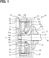
- FIG. 1 shows a schematic structure of a rotary electric machine for an internal combustion engine.
- An internal combustion engine system 10 includes an internal combustion engine (engine 12) and a rotary electric machine for the internal combustion engine (hereinafter, simply referred to as a rotary electric machine 15).
- An example of applications of the rotary electric machine 15 is a generator driven by the engine 12.
- the rotary electric machine 15 supplies electric power to a plurality of electric loads including a battery.
- the usage of the rotary electric machine 15 may be a generator motor.
- the rotary electric machine 15 functions as both a generator and an electric motor.
- the rotary electric machine 15 functions as a starter motor for starting the engine 12, for example.
- the engine 12 has a member 13.
- the body 13 is provided by a crankcase or a cover of the engine 12.
- the body 13 defines an accommodation chamber 13a for accommodating the rotary electric machine 15.
- the accommodation chamber 13a is a dry cavity filled with air or a wet cavity in which air and lubricating oil or air and cooling liquid are mixed.
- the rotary electric machine 15 radiates heat to the fluid in the accommodation chamber 13a.
- the fluid includes air, lubricating oil, and/or cooling liquid.
- the engine 12 has a rotary shaft 14.
- the rotary shaft 14 is provided by a crankshaft or a shaft that interlocks with the crankshaft.
- the rotary shaft 14 is connected to the rotary electric machine 15.
- the rotary electric machine 15 is linked to the engine 12 by being mounted on the engine 12.
- the engine 12 is a vehicle engine mounted on a vehicle or a general-purpose engine.
- vehicle should be interpreted in a broad sense, and includes moving objects such as vehicles, ships, and aircrafts, and fixed objects such as amusement equipment and simulation equipment.
- the general-purpose engine can be used, for example, as a generator and a pump.
- the engine 12 is mounted on a saddle-ride type vehicle.
- the rotary electric machine 15 is assembled to the body 13 and the rotary shaft 14.
- the rotary electric machine 15 is an outer rotor type rotary electric machine.
- the rotary electric machine 15 includes a rotor 21 and a stator 31.
- axial direction refers to a direction along a central axis AX when the rotor 21, the stator 31, or the stator core 32 is regarded as a cylinder.
- radial direction refers to a radial direction when the rotor 21, the stator 31, or the stator core 32 is regarded as a cylinder.
- the rotor 21 is a field element.
- the rotor 21 is entirely cup-shaped.
- the rotor 21 is fixed to the end portion of the rotary shaft 14.
- the rotor 21 rotates together with the rotary shaft 14.
- the rotor 21 has a cup-shaped rotor core 22.
- the rotor 21 has a permanent magnet 23 disposed on an inner surface of the rotor core 22.
- the rotor 21 provides a rotating magnetic field by the permanent magnet 23.
- the permanent magnet 23 is provided by a plurality of arc-shaped magnets.
- the rotor 21 has a holder 24 for fixing the permanent magnet 23.
- the permanent magnet 23 may be fixed by an adhesive.
- the rotor core 22 is connected to the rotary shaft 14.
- the rotary shaft 14 has an outer surface 14a for receiving the rotor core 22.
- the outer surface 14a is a tapered surface that is tapered off.
- the rotor core 22 and the rotary shaft 14 are connected via a positioning mechanism in a rotational direction such as key fitting.
- the rotor core 22 is fastened and fixed to the rotary shaft 14 by a nut 14b that is a fixing member.
- the rotor core 22 provides a yoke for a permanent magnet to be described later.
- the rotor core 22 is made of a magnetic metal.
- the rotor core 22 includes an inner cylinder 22a, an outer cylinder 22b, and a bottom plate 22c.
- the inner cylinder 22a is connected to the rotary shaft 14.
- the inner cylinder 22a provides a boss portion.
- the outer cylinder 22b is a circular cylindrical shape.
- the outer cylinder 22b is located on a radial direction outside of the inner cylinder 22a and away from the inner cylinder 22a.
- the outer cylinder 22b supports the permanent magnet 23 on the inner surface.
- the bottom plate 22c is an annular plate.
- the bottom plate 22c extends on one end of the outer cylinder.
- the bottom plate 22c extends between the inner cylinder 22a and the outer cylinder 22b.
- the inner cylinder 22a has a through hole that receives the rotary shaft 14.
- the inner cylinder 22a has an inner surface 22d.
- the inner surface 22d is a tapered surface that contacts the outer surface 14a.
- the inner cylinder 22a, the outer cylinder 22b, and the bottom plate 22c are integrally formed of a continuous material.
- the inner cylinder 22a, the outer cylinder 22b, and the bottom plate 22c may be provided by a plurality of members.
- the boss portion that provides the inner cylinder 22a may be provided by another member and connected by a connecting member such as a rivet.
- the bottom plate 22c has a through hole 22e.
- the through hole 22e communicates the inside and the outside of the rotor 21 in a cup shape.
- the through hole 22e is located on the radial direction outside out of the annular range provided by the bottom plate 22c.
- the through hole 22e is open to the inside of the rotor 21 at one end.
- the other end of the through hole 22e is open only in the axial direction end surface of the bottom plate 22c.
- the holder 24 is a cup-shaped member.
- the holder 24 extends over among from the end surface of the permanent magnet 23 to the inner surface of the permanent magnet 23 and the inner surface of the bottom plate 22c.
- the holder 24 is fixed to the bottom plate 22c by a fixing member such as a rivet.
- the holder 24 fixes the permanent magnet 23 to the rotor core 22.
- the holder 24 provides a radial direction inner surface 24a.
- the radial direction inner surface 24a is also the inner surface of the rotor 21.
- the holder 24 is made of thin non-magnetic metal.
- the holder 24 is formed so as not to cover the through hole 22e.
- the holder 24 may have a through hole corresponding to the through hole 22e.
- the through hole 22e is recognized as a hole in the rotor 21 as well as a hole in the rotor core 22.
- the through hole 22e communicates the inside and outside of the rotor 21.
- the stator 31 is an armature element.
- the stator 31 is an annular member.
- the stator 31 is an outer salient pole type stator.
- the stator 31 is fixed to the body 13.
- the stator 31 has a through hole that can receive the rotary shaft 14 and the inner cylinder 22a.
- the stator 31 has an outer peripheral surface opposed to the inner surface of the rotor 21 via a gap.
- the stator 31 has a stator core 32.
- the stator core 32 is disposed inside the rotor 21.
- the stator core 32 is fixed to body 13.
- a shape of the stator core 32 is characterized by an annular portion provided on a radial direction inside and a plurality of teeth (salient poles) provided on a radial direction outside.
- the stator 31 has a stator coil 33 attached to a stator core 32.
- the stator coil 33 is attached to a part of the stator core 32.
- the stator coil 33 is wound around the stator core 32.
- the stator coil 33 provides a single-phase winding or a multi-phase winding.
- the stator coil 33 is disposed on radial direction outside teeth of the stator core 32.
- the stator coil 33 provides an armature winding.
- the stator core 32 is fixed to the body 13 by bolts 35 that are fixing members.
- the bolt 35 passes through the stator core 32.
- the bolt 35 fixes the stator core 32 to a cover of the body 13.
- the bolt 35 may be regarded as a part of the rotary electric machine 15 or a part of the engine 12.
- FIG. 2 is a plan view of the rotor 21 in the direction of arrow II in FIG. 1 .
- the arrow R21 is the rotation direction R21 of the rotor 21.
- a leading side of an object with respect to the direction of the rotation direction R21 may be referred to as a forward direction
- a trailing side of the object with respect to the rotation direction R21 may be referred to as a backward direction.
- the positions of the plurality of through holes 22e in the rotor 21 are illustrated relatively accurately.
- the rotor 21 has a plurality of through holes 22e.
- the plurality of through holes 22e are arranged at equal intervals.
- the plurality of through holes 22e are dispersively arranged apart from each other on the axial direction inner surface of the rotor 21.
- the axial direction inner surface of the rotor 21 extends between the two through holes 22e that are adjacent to each other in the circumferential direction.
- the through hole 22e is positioned on a radial direction outside on the axial direction inner surface of the rotor 21.
- the through hole 22e is close to the radial direction inner surface 24a of the rotor 21.
- the through hole 22e is clearly separated from the inner cylinder 22a.
- the axial direction inner surface of the rotor 21 extends between the inner cylinder 22a and the through hole 22e. There is a limited axial direction inner surface between the radial direction inner surface 24a and the through hole 22e. An edge of the through hole 22e may be in contact with the radially inner surface 24a.
- the through hole 22e is a circular hole.
- the rotary electric machine 15 has a fan 25.
- the fan 25 has an inner ring 26, an outer ring 27, and a partition member 28 extending between the inner ring 26 and the outer ring 27.
- the partition member 28 crosses over the through hole 22e so as to partition the through hole 22e.
- the partition member 28 is also called a bridging portion, a blade, or a rib.
- the partition member 28 has an inner ring connecting portion C1 that connects the inner ring 26 and the partition member 28, and an outer ring connecting portion C2 that connects the outer ring 27 and the partition member 28.
- the inner ring connecting portion C1 is also called a first connecting portion.
- the outer ring connecting portion C2 is also called a second connecting portion.
- the inner ring connecting portion C1 and the outer ring connecting portion C2 are offset in the rotation direction R21. That is, the through hole 22e is positioned between the inner ring connecting portion C1 and the outer ring connecting portion C2.
- the inner ring 26 is fixed by a flange 22f formed on the inner cylinder 22a.
- the fan 25 can be fixed to the rotor 21 by various fixing mechanisms such as caulking by the flange 22f, adhesion, and press fitting.
- the fan 25 extends from the inner cylinder 22a along the axial direction inner surface of the rotor 21.
- the fan 25 reaches a radially outer side edge of the axial direction inner surface of the rotor 21 via the axial direction inner surface of the rotor 21.
- the fan 25 is a part of the rotor 21.
- the fan 25 is made of resin.
- the fan 25 may be made of metal such as aluminum.
- the fan 25 has a plurality of partition members 28.
- the plurality of partition members 28 are arranged at equal intervals.
- the plurality of partition members 28 are dispersively arranged apart from each other on the axial direction inner surface of the rotor 21.
- the one partition member 28 extends outward from the inner ring 26 in the radially outer side.
- the partition member 28 extends from the inner ring 26 in parallel with the tangential direction of the inner ring 26.
- the partition member 28 has a straight portion 28a and a curved portion 28b.
- the straight portion 28a occupies a radial direction inside portion rather than the curved portion 28b.
- the curved portion 28b occupies a radial direction outside portion rather than the straight portion 28a.
- the curved portion 28b is curved so as to be curled in the backward direction.
- the partition member 28 reaches the outer ring 27 after passing through the straight portion 28a and the curved portion 28b.
- the partition member 28 has a sweepback angle RDn.
- the sweepback angle RDn is an inclination angle of the partition member 28 with respect to the radial direction.
- the partition member 28 is inclined with respect to the radial direction so as to gradually recede backward in the rotational direction R21 from the radial direction inside toward the radial direction outside. It is possible to assume a partition member axis BLn as a center of one partition member 28. Here, a center of the straight portion 28a of the partition member 28 is the partition member axis BLn. Further, it is possible to assume a radial direction axis Rn passing through an intersection of the inner ring 26 and one partition member 28.
- the sweepback angle RDn of the partition member 28 is indicated by an arrow.
- the curved portion 28b is bent rearward from the partition member 28 in the rotation direction R21.
- the center defining the curved portion 28b is located behind the partition member 28 in the rotation direction R21.
- the partition member 28 extends from the inner ring 26 toward the outer ring 27 with the sweepback angle RDn.
- the sweepback angle RDn may be defined by the straight portion 28a and the curved portion 28b as a whole. Also in this case, the partition member 28 has the sweepback angle.
- the partition member 28 has a front edge that is the leading side in the rotation direction R21 and a rear edge that is the trailing side in the rotation direction R21.
- the front edge extends between an inner end point L1 on the radial direction inside and an outer end point L3 on the radial direction outside.
- the front edge is curved so as to be convex toward the front in the rotation direction R21.
- the front edge has a boundary point L2 between the straight portion 28a and the curved portion 28b.
- the rear edge extends between an inner end point T1 on the radial direction inside and an outer end point T3 on the radial direction outside.
- the rear edge is curved so as to be concave toward the front in the rotation direction R21.
- the rear edge has a boundary point T2 between the straight portion 28a and the curved portion 28b.
- the partition member 28 is arranged within the rotor 21.
- the partition member 28 is arranged on the bottom plate 22c inside the outer cylinder 22b.
- the plurality of partition members 28 are in contact with the surface inside the rotor 21, for example, the surface of the bottom plate 22c.
- the partition member 28 is arranged on the surface of the bottom plate 22c that faces the stator 31.
- the plurality of partition members 28 are radially arranged at equal intervals.
- the plurality of partition members 28 are arranged at the same angular intervals as the plurality of through holes 22e.
- the plurality of partition members 28 are arranged in a spiral shape gradually expanding from the inner cylinder 22a to the outer cylinder 22b along the rotation direction of the rotor 21. All the partition members 28 have the same shape.
- a cavity 22g corresponding to an axial direction height of the partition member 28 is defined between the two partition members 28 adjacent to each other in the circumferential direction.
- the cavity 22g is fan-shaped.
- the cavity 22g gradually moves in the backward direction as it is towards from a radial direction inner end to a radial direction outer end. Since the partition member 28 has the sweepback angle RDn, the partition member 28 generates a flow along the partition member 28 gradually from the radial direction inside toward the radial direction outside.
- the flow includes various fluid flows such as a case of air, a case of a mixture containing oil, and a case of liquid.
- One partition member 28 is arranged so as to partition one through hole 22e.
- the partition member 28 is arranged so as to pass through substantially the center of the through hole 22e.
- the partition member 28 is arranged so that the curved portion 28b is positioned above the through hole 22e.
- the partition member 28 is arranged so that the curved portion 28b is mainly positioned above the through hole 22e.
- At least one partition member 28 crosses over at least one through hole 22e.
- At least one partition member 28 partitions one through hole 22e.
- the partition member 28 is arranged so as to partition the through hole 22e into a first region 22h and a second region 22i. The first region 22h and the second region 22i are in communication with the fluid.
- the partition member 28 obliquely crosses over the through hole 22e while being inclined with respect to the radial direction.
- the partition member 28 diagonally crosses over the through hole 22e while extending in the backward direction on the through hole 22e.
- the boundary points L2 and T2 are located on the through hole 22e.
- All of the plurality of partition members 28 partition the plurality of through holes 22e.
- All of the plurality of through holes 22e are partitioned by a plurality of partition members 28. Each of the plurality of partition members 28 crosses over each of the plurality of through holes 22e.
- the partition member 28 is continuously formed from the inner cylinder 22a to the outer cylinder 22b.
- the partition member 28 is arranged so as to straddle over the through hole 22e. Further, the partition member 28 is also arranged inside the rotor 21 on the side surface facing the stator 31. It is desirable that the partition members 28 be arranged in this manner. As a result, an interaction with the air described later occurs.
- the first region 22h is located forward of the second region 22i with respect to the rotation direction R21. Therefore, the first region 22h is also called a leading region.
- the second region 22i is located backward of the first region 22h with respect to the rotation direction R21. Therefore, the second region 22i is also called a trailing region.
- An area of the first region 22h is smaller than an area of the second region 22i. A difference in area contributes to the generation of a pressure difference described later.
- the partition member 28 Since the partition member 28 has the sweepback angle RDn, the characteristic shapes of the first region 22h and the second region 22i can be obtained in the through hole 22e.
- the through hole 22e is divided into the first region 22h and the second region 22i by the curved portion 28b having a large sweepback angle.
- the first region 22h is located outside rather than the second region 22i with respect to the radial direction. Therefore, the first region 22h is also called an outside region.
- the second region 22i is located inside rather than the first region 22h with respect to the radial direction. Therefore, the second region 22i is also called an inside region.
- the sweepback angle RDn gives the through hole 22e not only the characteristic shape of the leading region and the trailing region but also the characteristic shape of the outside region and the inside region.
- FIG. 3 shows a schematic cross section taken along the line III-III in FIG. 2 .
- the bottom plate 22c and the fan 25 are illustrated.
- the partition member 28 is positioned so as to partition the through hole 22e into the first region 22h and the second region 22i.
- the partition member 28 generates an outward flow OWF passing through the through hole 22e and an inward flow IWF.
- On the leading side LS an outward flow OWF that goes from the inside of the rotor 21 to the outside thereof occurs.
- At the trailing side TS an inward flow IWF is generated from the outside of the rotor 21 toward the inside. This promotes the flow of fluid through the through hole 22e.
- the flow of the fluid promotes heat dissipation of the rotor 21 and heat dissipation of the stator 31.
- the partition member 28 due to the characteristic shapes of the outer region and the inner region, the partition member 28 generates a component inclined in the radial direction.
- the first region 22h which is the outer region, gradually transitions radial direction outside along the partition member 28. Due to the sweepback angle RDn, the partition member 28 generates a flow toward from the radial direction inside to the radial direction outside.
- the partition member 28 produces an outward flow OWF that is inclined from the radial direction inside to the radial direction outside.
- the outward flow OWF in the first region 22h promotes discharge from the radial direction inside of the rotor 21 to the radial direction outside.
- the second region 22i which is the inner region, gradually transitions radial direction outside along the partition member 28. Due to the sweepback angle RDn, the partition member 28 generates a flow toward from the radial direction inside to the radial direction outside.
- the partition member 28 produces an inward flow IWF that is inclined from the radial direction inside to the radial direction outside.
- the inward flow IWF in the second region 22i promotes introduction from the radial direction inside of the rotor 21 to the radial direction outside.
- the disclosure in this specification, the drawings, and the like is not limited to the illustrated embodiments.
- the disclosure encompasses the illustrated embodiments and variations thereof by those skilled in the art.
- the present disclosure is not limited to the combinations of components and/or elements shown in the embodiments.
- the present disclosure may be implemented in various combinations.
- the present disclosure may have additional portions which may be added to the embodiments.
- the present disclosure encompasses omission of the components and/or elements of the embodiments.
- the present disclosure encompasses the replacement or combination of components and/or elements between one embodiment and another.
- the disclosed technical scope is not limited to the description of the embodiment. Several technical scopes disclosed are indicated by descriptions in the claims and should be understood to include all modifications within the meaning and scope equivalent to the descriptions in the claims.
- the above embodiment includes the fan 25 made of resin.
- the fan 25 may be made of metal.
- the fan 25 is preferably a non-magnetic material.
- the fan 25 made of a non-magnetic material prevents leakage of magnetic flux, and also suppresses iron loss in the fan 25 due to the leakage magnetic flux.
- the fan 25 may also be provided by the holder 24.
- a raised portion corresponding to the partition member 28 may be formed in a part of the holder 24.
- the holder 24 may be insert-molded on the resin fan 25.
- the plurality of through holes 22e are arranged at equal angular intervals. Further, the plurality of through holes 22e are equidistant from the central axis AX. Alternatively, the plurality of through holes 22e may be arranged at unequal intervals. Further, the plurality of through holes 22e may be dispersed with respect to the distance from the central axis AX. For example, the plurality of through holes 22e may be alternately different in distance from the central axis AX.
- the partition member 28 may divide the through hole 22e.
- the partition member 28 only needs to traverse the through hole 22e, and various modifications can be made with ribs or fins.
- the curved portion 28b is mainly arranged on the through hole 22e.
- the straight portion 28a and the curved portion 28b may be arranged on the through hole 22e.
- only the curved portion 28b may be arranged on the through hole 22e.
- only the straight portion 28a may be arranged on the through hole 22e.
- the plurality of partition members 28 and the plurality of through holes 22e are associated with each other in a one-to-one relationship. This configuration contributes to high efficiency.
- the through hole 22e may include a plurality of through holes having different diameters.
Landscapes
- Engineering & Computer Science (AREA)
- Power Engineering (AREA)
- Chemical & Material Sciences (AREA)
- Combustion & Propulsion (AREA)
- Mechanical Engineering (AREA)
- General Engineering & Computer Science (AREA)
- Motor Or Generator Cooling System (AREA)
- Iron Core Of Rotating Electric Machines (AREA)
Abstract
Description
- The present application claims the benefit of priority from Japanese Patent Application No.
2018-059818 - The disclosure in this specification relates to a rotary electric machine for an internal combustion engine and its rotor.
- Patent Literatures 1 and 2 disclose a rotary electric machine for an internal combustion engine and a rotor thereof. The rotary electric machine for an internal combustion engine includes a fan. The contents of literatures listed as the citation list are incorporated by reference as explanation of technical elements in this specification.
-
- [Patent Document 1] JPS59-35547A
- [Patent Literature 2]
JP2001-45714A - In the configuration of Patent Literature 1, a fan component is provided inside a rotary electric machine. The fan produces a flow inside a rotary electric machine, especially a rotor. On the other hand, Patent Literature 2 introduces a flow of mist containing oil from an outside of the rotor. In rotary electric machines for internal combustion engines, efficient generation of flow is required. In the above aspects, or in other aspects not mentioned, there is a need for further improvements in a rotary electric machine for an internal combustion engine and its stator.
- It is an object of this disclosure to provide a rotary electric machine for an internal combustion engine and a rotor that efficiently generate a flow by components arranged inside a rotor.
- A rotor of a rotary electric machine for an internal combustion engine disclosed herein comprising: a rotor core (22) having a cylindrical outer cylinder (22b) and a bottom plate (22c) extending on one end of the outer cylinder and having a through hole (22e) penetrating the bottom plate; and a partition member (28) which is arranged inside the outer cylinder and crosses the through hole so as to partition the through hole into a first region (22h) and a second region (22i).
- The rotor of the disclosed rotary electric machine for an internal combustion engine generates a flow through the through hole by the partition member. The partition member partitions the through hole into the first region and the second region. The partition member produces a flow in the first region and also produces a flow in the second region. The rotor can utilize the flow in the first region and the flow in the second region. As a result, the rotor of a rotary electric machine for the internal combustion engine that efficiently generates a flow by the partition member arranged inside the rotor is provided.
- The rotary electric machine for an internal combustion engine disclosed herein includes the rotor (21) and a stator (31) facing the rotor.
- The disclosed aspects in this specification adopt different technical solutions from each other in order to achieve their respective objectives. Reference numerals in parentheses described in claims and this section exemplarily show corresponding relationships with parts of embodiments to be described later and are not intended to limit technical scopes. The objects, features, and advantages disclosed in this specification will become apparent by referring to following detailed descriptions and accompanying drawings.
-
- [
FIG. 1] FIG. 1 is a cross-sectional view of a rotary electric machine according to a first embodiment. - [
FIG. 2] FIG. 2 is a plan view of the inside of a rotor. - [
FIG. 3] FIG. 3 is a partial cross sectional view of the rotor. - Hereinafter, a plurality of embodiments will be described with reference to the drawings. In some embodiments, parts which are functionally and/or structurally corresponding and/or associated are given the same reference numerals, or reference numerals with different hundreds digit or higher digits. For corresponding parts and/or associated parts, additional explanations can be made to the description of other embodiments.
-
FIG. 1 shows a schematic structure of a rotary electric machine for an internal combustion engine. An internalcombustion engine system 10 includes an internal combustion engine (engine 12) and a rotary electric machine for the internal combustion engine (hereinafter, simply referred to as a rotary electric machine 15). An example of applications of the rotaryelectric machine 15 is a generator driven by theengine 12. In this case, the rotaryelectric machine 15 supplies electric power to a plurality of electric loads including a battery. The usage of the rotaryelectric machine 15 may be a generator motor. In this case, the rotaryelectric machine 15 functions as both a generator and an electric motor. In this case, the rotaryelectric machine 15 functions as a starter motor for starting theengine 12, for example. - The
engine 12 has amember 13. Thebody 13 is provided by a crankcase or a cover of theengine 12. Thebody 13 defines anaccommodation chamber 13a for accommodating the rotaryelectric machine 15. Theaccommodation chamber 13a is a dry cavity filled with air or a wet cavity in which air and lubricating oil or air and cooling liquid are mixed. The rotaryelectric machine 15 radiates heat to the fluid in theaccommodation chamber 13a. The fluid includes air, lubricating oil, and/or cooling liquid. Theengine 12 has arotary shaft 14. Therotary shaft 14 is provided by a crankshaft or a shaft that interlocks with the crankshaft. Therotary shaft 14 is connected to the rotaryelectric machine 15. - The rotary
electric machine 15 is linked to theengine 12 by being mounted on theengine 12. Theengine 12 is a vehicle engine mounted on a vehicle or a general-purpose engine. Here, the term vehicle should be interpreted in a broad sense, and includes moving objects such as vehicles, ships, and aircrafts, and fixed objects such as amusement equipment and simulation equipment. The general-purpose engine can be used, for example, as a generator and a pump. In this embodiment, theengine 12 is mounted on a saddle-ride type vehicle. - The rotary
electric machine 15 is assembled to thebody 13 and therotary shaft 14. The rotaryelectric machine 15 is an outer rotor type rotary electric machine. The rotaryelectric machine 15 includes arotor 21 and astator 31. In the following description, the term "axial direction" refers to a direction along a central axis AX when therotor 21, thestator 31, or thestator core 32 is regarded as a cylinder. In the following description, the term "radial direction" refers to a radial direction when therotor 21, thestator 31, or thestator core 32 is regarded as a cylinder. - The
rotor 21 is a field element. Therotor 21 is entirely cup-shaped. Therotor 21 is fixed to the end portion of therotary shaft 14. Therotor 21 rotates together with therotary shaft 14. Therotor 21 has a cup-shapedrotor core 22. Therotor 21 has a permanent magnet 23 disposed on an inner surface of therotor core 22. Therotor 21 provides a rotating magnetic field by the permanent magnet 23. The permanent magnet 23 is provided by a plurality of arc-shaped magnets. Therotor 21 has aholder 24 for fixing the permanent magnet 23. The permanent magnet 23 may be fixed by an adhesive. - The
rotor core 22 is connected to therotary shaft 14. Therotary shaft 14 has anouter surface 14a for receiving therotor core 22. Theouter surface 14a is a tapered surface that is tapered off. Therotor core 22 and therotary shaft 14 are connected via a positioning mechanism in a rotational direction such as key fitting. Therotor core 22 is fastened and fixed to therotary shaft 14 by anut 14b that is a fixing member. Therotor core 22 provides a yoke for a permanent magnet to be described later. Therotor core 22 is made of a magnetic metal. - The
rotor core 22 includes aninner cylinder 22a, anouter cylinder 22b, and abottom plate 22c. Theinner cylinder 22a is connected to therotary shaft 14. Theinner cylinder 22a provides a boss portion. Theouter cylinder 22b is a circular cylindrical shape. Theouter cylinder 22b is located on a radial direction outside of theinner cylinder 22a and away from theinner cylinder 22a. Theouter cylinder 22b supports the permanent magnet 23 on the inner surface. Thebottom plate 22c is an annular plate. Thebottom plate 22c extends on one end of the outer cylinder. Thebottom plate 22c extends between theinner cylinder 22a and theouter cylinder 22b. - The
inner cylinder 22a has a through hole that receives therotary shaft 14. Theinner cylinder 22a has aninner surface 22d. Theinner surface 22d is a tapered surface that contacts theouter surface 14a. In this embodiment, theinner cylinder 22a, theouter cylinder 22b, and thebottom plate 22c are integrally formed of a continuous material. Theinner cylinder 22a, theouter cylinder 22b, and thebottom plate 22c may be provided by a plurality of members. For example, the boss portion that provides theinner cylinder 22a may be provided by another member and connected by a connecting member such as a rivet. - The
bottom plate 22c has a throughhole 22e. The throughhole 22e communicates the inside and the outside of therotor 21 in a cup shape. The throughhole 22e is located on the radial direction outside out of the annular range provided by thebottom plate 22c. The throughhole 22e is open to the inside of therotor 21 at one end. The other end of the throughhole 22e is open only in the axial direction end surface of thebottom plate 22c. - The
holder 24 is a cup-shaped member. Theholder 24 extends over among from the end surface of the permanent magnet 23 to the inner surface of the permanent magnet 23 and the inner surface of thebottom plate 22c. Theholder 24 is fixed to thebottom plate 22c by a fixing member such as a rivet. Theholder 24 fixes the permanent magnet 23 to therotor core 22. Theholder 24 provides a radial directioninner surface 24a. The radial directioninner surface 24a is also the inner surface of therotor 21. Theholder 24 is made of thin non-magnetic metal. - The
holder 24 is formed so as not to cover the throughhole 22e. Theholder 24 may have a through hole corresponding to the throughhole 22e. As a result, the throughhole 22e is recognized as a hole in therotor 21 as well as a hole in therotor core 22. The throughhole 22e communicates the inside and outside of therotor 21. - The
stator 31 is an armature element. Thestator 31 is an annular member. Thestator 31 is an outer salient pole type stator. Thestator 31 is fixed to thebody 13. Thestator 31 has a through hole that can receive therotary shaft 14 and theinner cylinder 22a. Thestator 31 has an outer peripheral surface opposed to the inner surface of therotor 21 via a gap. - The
stator 31 has astator core 32. Thestator core 32 is disposed inside therotor 21. Thestator core 32 is fixed tobody 13. A shape of thestator core 32 is characterized by an annular portion provided on a radial direction inside and a plurality of teeth (salient poles) provided on a radial direction outside. - The
stator 31 has astator coil 33 attached to astator core 32. Thestator coil 33 is attached to a part of thestator core 32. Thestator coil 33 is wound around thestator core 32. Thestator coil 33 provides a single-phase winding or a multi-phase winding. Thestator coil 33 is disposed on radial direction outside teeth of thestator core 32. Thestator coil 33 provides an armature winding. Thestator core 32 is fixed to thebody 13 bybolts 35 that are fixing members. Thebolt 35 passes through thestator core 32. Thebolt 35 fixes thestator core 32 to a cover of thebody 13. Thebolt 35 may be regarded as a part of the rotaryelectric machine 15 or a part of theengine 12. -
FIG. 2 is a plan view of therotor 21 in the direction of arrow II inFIG. 1 . The arrow R21 is the rotation direction R21 of therotor 21. In the following description, a leading side of an object with respect to the direction of the rotation direction R21 may be referred to as a forward direction, and a trailing side of the object with respect to the rotation direction R21 may be referred to as a backward direction. The positions of the plurality of throughholes 22e in therotor 21 are illustrated relatively accurately. - The
rotor 21 has a plurality of throughholes 22e. The plurality of throughholes 22e are arranged at equal intervals. The plurality of throughholes 22e are dispersively arranged apart from each other on the axial direction inner surface of therotor 21. The axial direction inner surface of therotor 21 extends between the two throughholes 22e that are adjacent to each other in the circumferential direction. The throughhole 22e is positioned on a radial direction outside on the axial direction inner surface of therotor 21. The throughhole 22e is close to the radial directioninner surface 24a of therotor 21. The throughhole 22e is clearly separated from theinner cylinder 22a. The axial direction inner surface of therotor 21 extends between theinner cylinder 22a and the throughhole 22e. There is a limited axial direction inner surface between the radial directioninner surface 24a and the throughhole 22e. An edge of the throughhole 22e may be in contact with the radiallyinner surface 24a. The throughhole 22e is a circular hole. - Returning to
FIG. 1 , the rotaryelectric machine 15 has afan 25. Thefan 25 has aninner ring 26, anouter ring 27, and apartition member 28 extending between theinner ring 26 and theouter ring 27. Thepartition member 28 crosses over the throughhole 22e so as to partition the throughhole 22e. Thepartition member 28 is also called a bridging portion, a blade, or a rib. - The
partition member 28 has an inner ring connecting portion C1 that connects theinner ring 26 and thepartition member 28, and an outer ring connecting portion C2 that connects theouter ring 27 and thepartition member 28. The inner ring connecting portion C1 is also called a first connecting portion. The outer ring connecting portion C2 is also called a second connecting portion. The inner ring connecting portion C1 and the outer ring connecting portion C2 are offset in the rotation direction R21. That is, the throughhole 22e is positioned between the inner ring connecting portion C1 and the outer ring connecting portion C2. - The
inner ring 26 is fixed by aflange 22f formed on theinner cylinder 22a. Thefan 25 can be fixed to therotor 21 by various fixing mechanisms such as caulking by theflange 22f, adhesion, and press fitting. Thefan 25 extends from theinner cylinder 22a along the axial direction inner surface of therotor 21. Thefan 25 reaches a radially outer side edge of the axial direction inner surface of therotor 21 via the axial direction inner surface of therotor 21. Thefan 25 is a part of therotor 21. Thefan 25 is made of resin. Thefan 25 may be made of metal such as aluminum. - In
FIG. 2 , thefan 25 has a plurality ofpartition members 28. The plurality ofpartition members 28 are arranged at equal intervals. The plurality ofpartition members 28 are dispersively arranged apart from each other on the axial direction inner surface of therotor 21. - The one
partition member 28 extends outward from theinner ring 26 in the radially outer side. Thepartition member 28 extends from theinner ring 26 in parallel with the tangential direction of theinner ring 26. Thepartition member 28 has astraight portion 28a and acurved portion 28b. Thestraight portion 28a occupies a radial direction inside portion rather than thecurved portion 28b. Thecurved portion 28b occupies a radial direction outside portion rather than thestraight portion 28a. Thecurved portion 28b is curved so as to be curled in the backward direction. Thepartition member 28 reaches theouter ring 27 after passing through thestraight portion 28a and thecurved portion 28b. - The
partition member 28 has a sweepback angle RDn. The sweepback angle RDn is an inclination angle of thepartition member 28 with respect to the radial direction. Thepartition member 28 is inclined with respect to the radial direction so as to gradually recede backward in the rotational direction R21 from the radial direction inside toward the radial direction outside. It is possible to assume a partition member axis BLn as a center of onepartition member 28. Here, a center of thestraight portion 28a of thepartition member 28 is the partition member axis BLn. Further, it is possible to assume a radial direction axis Rn passing through an intersection of theinner ring 26 and onepartition member 28. In this case, the sweepback angle RDn of thepartition member 28 is indicated by an arrow. Thecurved portion 28b is bent rearward from thepartition member 28 in the rotation direction R21. In other words, the center defining thecurved portion 28b is located behind thepartition member 28 in the rotation direction R21. Thepartition member 28 extends from theinner ring 26 toward theouter ring 27 with the sweepback angle RDn. The sweepback angle RDn may be defined by thestraight portion 28a and thecurved portion 28b as a whole. Also in this case, thepartition member 28 has the sweepback angle. - The
partition member 28 has a front edge that is the leading side in the rotation direction R21 and a rear edge that is the trailing side in the rotation direction R21. The front edge extends between an inner end point L1 on the radial direction inside and an outer end point L3 on the radial direction outside. The front edge is curved so as to be convex toward the front in the rotation direction R21. The front edge has a boundary point L2 between thestraight portion 28a and thecurved portion 28b. The rear edge extends between an inner end point T1 on the radial direction inside and an outer end point T3 on the radial direction outside. The rear edge is curved so as to be concave toward the front in the rotation direction R21. The rear edge has a boundary point T2 between thestraight portion 28a and thecurved portion 28b. - The
partition member 28 is arranged within therotor 21. Thepartition member 28 is arranged on thebottom plate 22c inside theouter cylinder 22b. The plurality ofpartition members 28 are in contact with the surface inside therotor 21, for example, the surface of thebottom plate 22c. Thepartition member 28 is arranged on the surface of thebottom plate 22c that faces thestator 31. - The plurality of
partition members 28 are radially arranged at equal intervals. The plurality ofpartition members 28 are arranged at the same angular intervals as the plurality of throughholes 22e. The plurality ofpartition members 28 are arranged in a spiral shape gradually expanding from theinner cylinder 22a to theouter cylinder 22b along the rotation direction of therotor 21. All thepartition members 28 have the same shape. - A
cavity 22g corresponding to an axial direction height of thepartition member 28 is defined between the twopartition members 28 adjacent to each other in the circumferential direction. Thecavity 22g is fan-shaped. Thecavity 22g gradually moves in the backward direction as it is towards from a radial direction inner end to a radial direction outer end. Since thepartition member 28 has the sweepback angle RDn, thepartition member 28 generates a flow along thepartition member 28 gradually from the radial direction inside toward the radial direction outside. The flow includes various fluid flows such as a case of air, a case of a mixture containing oil, and a case of liquid. - One
partition member 28 is arranged so as to partition one throughhole 22e. Thepartition member 28 is arranged so as to pass through substantially the center of the throughhole 22e. Thepartition member 28 is arranged so that thecurved portion 28b is positioned above the throughhole 22e. Thepartition member 28 is arranged so that thecurved portion 28b is mainly positioned above the throughhole 22e. At least onepartition member 28 crosses over at least one throughhole 22e. At least onepartition member 28 partitions one throughhole 22e. Thepartition member 28 is arranged so as to partition the throughhole 22e into afirst region 22h and asecond region 22i. Thefirst region 22h and thesecond region 22i are in communication with the fluid. Thepartition member 28 obliquely crosses over the throughhole 22e while being inclined with respect to the radial direction. Thepartition member 28 diagonally crosses over the throughhole 22e while extending in the backward direction on the throughhole 22e. The boundary points L2 and T2 are located on the throughhole 22e. All of the plurality ofpartition members 28 partition the plurality of throughholes 22e. All of the plurality of throughholes 22e are partitioned by a plurality ofpartition members 28. Each of the plurality ofpartition members 28 crosses over each of the plurality of throughholes 22e. - The
partition member 28 is continuously formed from theinner cylinder 22a to theouter cylinder 22b. Thepartition member 28 is arranged so as to straddle over the throughhole 22e. Further, thepartition member 28 is also arranged inside therotor 21 on the side surface facing thestator 31. It is desirable that thepartition members 28 be arranged in this manner. As a result, an interaction with the air described later occurs. - The
first region 22h is located forward of thesecond region 22i with respect to the rotation direction R21. Therefore, thefirst region 22h is also called a leading region. Thesecond region 22i is located backward of thefirst region 22h with respect to the rotation direction R21. Therefore, thesecond region 22i is also called a trailing region. An area of thefirst region 22h is smaller than an area of thesecond region 22i. A difference in area contributes to the generation of a pressure difference described later. - Since the
partition member 28 has the sweepback angle RDn, the characteristic shapes of thefirst region 22h and thesecond region 22i can be obtained in the throughhole 22e. In particular, the throughhole 22e is divided into thefirst region 22h and thesecond region 22i by thecurved portion 28b having a large sweepback angle. As a result, thefirst region 22h is located outside rather than thesecond region 22i with respect to the radial direction. Therefore, thefirst region 22h is also called an outside region. Thesecond region 22i is located inside rather than thefirst region 22h with respect to the radial direction. Therefore, thesecond region 22i is also called an inside region. The sweepback angle RDn gives the throughhole 22e not only the characteristic shape of the leading region and the trailing region but also the characteristic shape of the outside region and the inside region. -
FIG. 3 shows a schematic cross section taken along the line III-III inFIG. 2 . Here, thebottom plate 22c and thefan 25 are illustrated. When therotor 21 rotates in the rotation direction R21, the air outside therotor 21 flows as the outer flow OTF, and the air inside therotor 21 flows as the inner flow INF. Thepartition member 28 generates a rising flow LF that flows so as to avoid thepartition member 28. At this time, the pressure increases on the leading side LS of thepartition member 28. A pressure drop occurs at the trailing side TS of thepartition member 28. - The
partition member 28 is positioned so as to partition the throughhole 22e into thefirst region 22h and thesecond region 22i. Thepartition member 28 generates an outward flow OWF passing through the throughhole 22e and an inward flow IWF. On the leading side LS, an outward flow OWF that goes from the inside of therotor 21 to the outside thereof occurs. At the trailing side TS, an inward flow IWF is generated from the outside of therotor 21 toward the inside. This promotes the flow of fluid through the throughhole 22e. The flow of the fluid promotes heat dissipation of therotor 21 and heat dissipation of thestator 31. - Further, due to the characteristic shapes of the outer region and the inner region, the
partition member 28 generates a component inclined in the radial direction. Thefirst region 22h, which is the outer region, gradually transitions radial direction outside along thepartition member 28. Due to the sweepback angle RDn, thepartition member 28 generates a flow toward from the radial direction inside to the radial direction outside. Thepartition member 28 produces an outward flow OWF that is inclined from the radial direction inside to the radial direction outside. The outward flow OWF in thefirst region 22h promotes discharge from the radial direction inside of therotor 21 to the radial direction outside. - The
second region 22i, which is the inner region, gradually transitions radial direction outside along thepartition member 28. Due to the sweepback angle RDn, thepartition member 28 generates a flow toward from the radial direction inside to the radial direction outside. Thepartition member 28 produces an inward flow IWF that is inclined from the radial direction inside to the radial direction outside. The inward flow IWF in thesecond region 22i promotes introduction from the radial direction inside of therotor 21 to the radial direction outside. - As a result, a flow is generated in which the outward flow OWF is discharged to the outside in the radial direction and the inflow IWF is taken from the inside in the radial direction. This flow suppresses a short circuit between the outward flow OWF and the inward flow IWF in one through
hole 22e. This promotes the flow of fluid through the throughhole 22e. The flow of the fluid promotes heat dissipation of therotor 21 and heat dissipation of thestator 31. - The disclosure in this specification, the drawings, and the like is not limited to the illustrated embodiments. The disclosure encompasses the illustrated embodiments and variations thereof by those skilled in the art. For example, the present disclosure is not limited to the combinations of components and/or elements shown in the embodiments. The present disclosure may be implemented in various combinations. The present disclosure may have additional portions which may be added to the embodiments. The present disclosure encompasses omission of the components and/or elements of the embodiments. The present disclosure encompasses the replacement or combination of components and/or elements between one embodiment and another. The disclosed technical scope is not limited to the description of the embodiment. Several technical scopes disclosed are indicated by descriptions in the claims and should be understood to include all modifications within the meaning and scope equivalent to the descriptions in the claims.
- The above embodiment includes the
fan 25 made of resin. Alternatively, thefan 25 may be made of metal. Thefan 25 is preferably a non-magnetic material. Thefan 25 made of a non-magnetic material prevents leakage of magnetic flux, and also suppresses iron loss in thefan 25 due to the leakage magnetic flux. Thefan 25 may also be provided by theholder 24. For example, a raised portion corresponding to thepartition member 28 may be formed in a part of theholder 24. Further, theholder 24 may be insert-molded on theresin fan 25. - In the above embodiment, the plurality of through
holes 22e are arranged at equal angular intervals. Further, the plurality of throughholes 22e are equidistant from the central axis AX. Alternatively, the plurality of throughholes 22e may be arranged at unequal intervals. Further, the plurality of throughholes 22e may be dispersed with respect to the distance from the central axis AX. For example, the plurality of throughholes 22e may be alternately different in distance from the central axis AX. - The
partition member 28 may divide the throughhole 22e. In other words, thepartition member 28 only needs to traverse the throughhole 22e, and various modifications can be made with ribs or fins. In the above embodiment, thecurved portion 28b is mainly arranged on the throughhole 22e. Alternatively, thestraight portion 28a and thecurved portion 28b may be arranged on the throughhole 22e. Further, only thecurved portion 28b may be arranged on the throughhole 22e. Further, only thestraight portion 28a may be arranged on the throughhole 22e. - In the above embodiment, the plurality of
partition members 28 and the plurality of throughholes 22e are associated with each other in a one-to-one relationship. This configuration contributes to high efficiency. Alternatively, there may be a throughhole 22e in which thepartition member 28 is not arranged. Further, there may be apartition member 28 that is not arranged on the throughhole 22e. In addition, the throughhole 22e may include a plurality of through holes having different diameters.
Claims (11)
- A rotor of a rotary electric machine for an internal combustion engine, comprising:a rotor core (22) having a cylindrical outer cylinder (22b) and a bottom plate (22c) extending on one end of the outer cylinder and having a through hole (22e) penetrating the bottom plate; anda partition member (28) which is arranged inside the outer cylinder and crosses the through hole so as to partition the through hole into a first region (22h) and a second region (22i).
- The rotor of a rotary electric machine for an internal combustion engine claimed in claim 1, wherein
the first region is a leading region located forward of the second region with respect to a rotation direction (R21) of the rotor, and
the second region is a trailing region located backward of the first region with respect to a rotation direction (R21) of the rotor. - The rotor of a rotary electric machine for an internal combustion engine claimed in claim 1 or 2, wherein
the first region is an outer region located outside the second region with respect to a radial direction of the rotor, and
the second region is an inner region located inside the first region with respect to the radial direction of the rotor. - The rotor of a rotary electric machine for an internal combustion engine claimed in any one of claims 1 to 3, wherein
the partition member crosses the through hole obliquely with respect to a radial direction of the rotor. - The rotor of a rotary electric machine for an internal combustion engine claimed in claim 4, wherein
the partition member extends at a sweepback angle (RDn) with respect to a rotation direction of the rotor. - The rotor of a rotary electric machine for an internal combustion engine claimed in any one of claims 1 to 5, wherein
the partition member has a straight portion (28a) and a curved portion (28b), and wherein
the straight portion is arranged so as to occupy a radial direction inside than the curved portion, and wherein
the curved portion is arranged so as to occupy a radial direction outside than the straight portion. - The rotor of a rotary electric machine for an internal combustion engine claimed in claim 6, wherein
the curved portion is arranged on the through hole. - The rotor of a rotary electric machine for an internal combustion engine claimed in any one of claims 1 to 7, further comprising:a plurality of the through holes, and a plurality of the partition members, whereineach of the plurality of partition members crosses each of the plurality of through holes.
- The rotor of a rotary electric machine for an internal combustion engine claimed in any one of claims 1 to 8, wherein
the partition member is provided as a part of a fan (25) having an inner ring (26) and an outer ring (27), extends between the inner ring and the outer ring, and is made of resin. - The rotor of a rotary electric machine for an internal combustion engine claimed in any one of claims 1 to 9, wherein
an area of the first region (22h) is smaller than an area of the second region (22i). - A rotary electric machine for an internal combustion engine, comprising:a rotor (21) claimed in any one of claims 1 to 10; anda stator (31) facing the rotor.
Applications Claiming Priority (2)
| Application Number | Priority Date | Filing Date | Title |
|---|---|---|---|
| JP2018059818 | 2018-03-27 | ||
| PCT/JP2019/011942 WO2019188734A1 (en) | 2018-03-27 | 2019-03-21 | Dynamo electrical machine for internal combustion engine, and rotor for same |
Publications (2)
| Publication Number | Publication Date |
|---|---|
| EP3780360A1 true EP3780360A1 (en) | 2021-02-17 |
| EP3780360A4 EP3780360A4 (en) | 2021-12-22 |
Family
ID=68061782
Family Applications (1)
| Application Number | Title | Priority Date | Filing Date |
|---|---|---|---|
| EP19775826.1A Withdrawn EP3780360A4 (en) | 2018-03-27 | 2019-03-21 | Dynamo electrical machine for internal combustion engine, and rotor for same |
Country Status (5)
| Country | Link |
|---|---|
| US (1) | US20210006114A1 (en) |
| EP (1) | EP3780360A4 (en) |
| JP (1) | JPWO2019188734A1 (en) |
| CN (1) | CN111903042A (en) |
| WO (1) | WO2019188734A1 (en) |
Cited By (1)
| Publication number | Priority date | Publication date | Assignee | Title |
|---|---|---|---|---|
| EP4195472A3 (en) * | 2021-12-10 | 2023-08-02 | Black & Decker, Inc. | Outer-rotor motor assembly |
Family Cites Families (16)
| Publication number | Priority date | Publication date | Assignee | Title |
|---|---|---|---|---|
| JPS5935547A (en) | 1982-08-18 | 1984-02-27 | Hitachi Ltd | Magnet generator for internal combustion engine |
| JPS60212613A (en) * | 1984-04-05 | 1985-10-24 | Hitachi Ltd | Internal-combustion engine magnetic generator and its cooling fan fixing device |
| ES2301228T3 (en) * | 1999-01-08 | 2008-06-16 | Lg Electronics Inc. | ROTOR STRUCTURE FOR A MOTOR WITHOUT TYPE BRUSHES WITH EXTERNAL ROTOR. |
| JP2001045714A (en) | 1999-08-03 | 2001-02-16 | Denso Corp | Magnet generator and manufacturing method thereof |
| JP2001061256A (en) * | 1999-08-20 | 2001-03-06 | Toshiba Corp | Fully closed outer rotor rotating electric machine |
| JP3671398B2 (en) * | 2002-05-16 | 2005-07-13 | 三菱電機株式会社 | Magnet generator |
| KR20060031272A (en) * | 2004-10-08 | 2006-04-12 | 주식회사 대우일렉트로닉스 | Heat radiator for rotor for outer rotor type motor |
| KR101072462B1 (en) * | 2004-11-17 | 2011-10-11 | 주식회사 대우일렉트로닉스 | Cooling apparatus of outter rotor motor for drum type washing machine |
| DE202006013319U1 (en) * | 2005-10-08 | 2007-02-15 | Ebm-Papst St. Georgen Gmbh & Co. Kg | External rotor electrical motor has a coupled impeller that induces cool air flow around the coils of an internal stator |
| JP2007129818A (en) * | 2005-11-02 | 2007-05-24 | Mitsubishi Electric Corp | Magnet generator |
| JP2008099506A (en) * | 2006-10-16 | 2008-04-24 | Matsushita Electric Ind Co Ltd | Induction motor |
| JP5367258B2 (en) * | 2007-12-27 | 2013-12-11 | 東芝産業機器製造株式会社 | Rotating electric machine |
| US8692432B2 (en) * | 2010-12-07 | 2014-04-08 | Regal Beloit America, Inc. | Permanent magnet rotors and methods of assembling the same |
| GB2517410A (en) * | 2013-07-16 | 2015-02-25 | Aim Co Ltd | A Stator and a Rotor for an Electric Motor |
| JP6032340B2 (en) * | 2014-11-28 | 2016-11-24 | デンソートリム株式会社 | Rotating electric machine for internal combustion engine |
| JP6550909B2 (en) * | 2015-05-08 | 2019-07-31 | 株式会社デンソー | Air blower |
-
2019
- 2019-03-21 EP EP19775826.1A patent/EP3780360A4/en not_active Withdrawn
- 2019-03-21 CN CN201980021905.8A patent/CN111903042A/en active Pending
- 2019-03-21 WO PCT/JP2019/011942 patent/WO2019188734A1/en not_active Ceased
- 2019-03-21 JP JP2020509928A patent/JPWO2019188734A1/en active Pending
-
2020
- 2020-09-23 US US17/030,098 patent/US20210006114A1/en not_active Abandoned
Cited By (3)
| Publication number | Priority date | Publication date | Assignee | Title |
|---|---|---|---|---|
| EP4195472A3 (en) * | 2021-12-10 | 2023-08-02 | Black & Decker, Inc. | Outer-rotor motor assembly |
| US12463502B2 (en) | 2021-12-10 | 2025-11-04 | Black & Decker Inc. | Outer-rotor motor assembly |
| US12549065B2 (en) | 2021-12-10 | 2026-02-10 | Black & Decker Inc. | Power tool with compact outer-rotor motor assembly |
Also Published As
| Publication number | Publication date |
|---|---|
| CN111903042A (en) | 2020-11-06 |
| WO2019188734A1 (en) | 2019-10-03 |
| US20210006114A1 (en) | 2021-01-07 |
| JPWO2019188734A1 (en) | 2021-03-11 |
| EP3780360A4 (en) | 2021-12-22 |
Similar Documents
| Publication | Publication Date | Title |
|---|---|---|
| KR101738208B1 (en) | Electrical machine cooling system and method | |
| EP1876687B1 (en) | Brushless fan motor | |
| KR101814847B1 (en) | Electric machine cooling system and method | |
| CN107448394B (en) | Electric centrifugal pump | |
| JP2013115848A (en) | Cooling structure of rotating electric machine | |
| JP5899716B2 (en) | Rotor structure of rotating electrical machine | |
| EP3144538B1 (en) | Electric pump | |
| KR20170077516A (en) | Rotor assembly and motor including the same | |
| JP6085267B2 (en) | Rotating electric machine | |
| EP3780360A1 (en) | Dynamo electrical machine for internal combustion engine, and rotor for same | |
| JP6938767B2 (en) | Rotating machine for internal combustion engine and its rotor | |
| JP2024082140A (en) | motor | |
| EP4145683B1 (en) | Hollow shaft for a rotor of electric motor | |
| JP7424842B2 (en) | rotating electric machine | |
| JP7214577B2 (en) | STARTER GENERATOR AND STARTER GENERATOR MANUFACTURING METHOD | |
| EP2918003B1 (en) | Method and device for liquid cooling of an electric motor | |
| JP2011250562A (en) | Rotary electric machine | |
| CN114868324A (en) | Cooling type rotating electric machine | |
| JP7840245B2 (en) | Pumping device | |
| JP7468591B1 (en) | Cooling structure for rotating electric machine and rotating electric machine | |
| AU2021403892B2 (en) | Alternator assembly | |
| JP2013126295A (en) | Rotating electric machine | |
| CN121816681A (en) | Rotor and hydraulic pump | |
| WO2025188556A1 (en) | An electric machine, and a cooling system for an electric machine | |
| JP2026035972A (en) | Pump equipment |
Legal Events
| Date | Code | Title | Description |
|---|---|---|---|
| STAA | Information on the status of an ep patent application or granted ep patent |
Free format text: STATUS: THE INTERNATIONAL PUBLICATION HAS BEEN MADE |
|
| PUAI | Public reference made under article 153(3) epc to a published international application that has entered the european phase |
Free format text: ORIGINAL CODE: 0009012 |
|
| STAA | Information on the status of an ep patent application or granted ep patent |
Free format text: STATUS: REQUEST FOR EXAMINATION WAS MADE |
|
| 17P | Request for examination filed |
Effective date: 20200820 |
|
| AK | Designated contracting states |
Kind code of ref document: A1 Designated state(s): AL AT BE BG CH CY CZ DE DK EE ES FI FR GB GR HR HU IE IS IT LI LT LU LV MC MK MT NL NO PL PT RO RS SE SI SK SM TR |
|
| AX | Request for extension of the european patent |
Extension state: BA ME |
|
| DAV | Request for validation of the european patent (deleted) | ||
| DAX | Request for extension of the european patent (deleted) | ||
| A4 | Supplementary search report drawn up and despatched |
Effective date: 20211119 |
|
| RIC1 | Information provided on ipc code assigned before grant |
Ipc: H02K 1/32 20060101ALI20211115BHEP Ipc: H02K 1/27 20060101ALI20211115BHEP Ipc: F02N 11/04 20060101ALI20211115BHEP Ipc: H02K 21/22 20060101ALI20211115BHEP Ipc: H02K 9/06 20060101AFI20211115BHEP |
|
| STAA | Information on the status of an ep patent application or granted ep patent |
Free format text: STATUS: THE APPLICATION HAS BEEN WITHDRAWN |
|
| 18W | Application withdrawn |
Effective date: 20220908 |