EP3780305A1 - Inverter arrangement for wind turbines and photovoltaic installations - Google Patents
Inverter arrangement for wind turbines and photovoltaic installations Download PDFInfo
- Publication number
- EP3780305A1 EP3780305A1 EP20188234.7A EP20188234A EP3780305A1 EP 3780305 A1 EP3780305 A1 EP 3780305A1 EP 20188234 A EP20188234 A EP 20188234A EP 3780305 A1 EP3780305 A1 EP 3780305A1
- Authority
- EP
- European Patent Office
- Prior art keywords
- intermediate circuit
- inverter
- inverters
- partial
- wind energy
- Prior art date
- Legal status (The legal status is an assumption and is not a legal conclusion. Google has not performed a legal analysis and makes no representation as to the accuracy of the status listed.)
- Pending
Links
- 238000009434 installation Methods 0.000 title claims description 13
- 230000005855 radiation Effects 0.000 claims description 30
- 230000001172 regenerating effect Effects 0.000 claims description 29
- 238000000034 method Methods 0.000 claims description 24
- 238000004804 winding Methods 0.000 claims description 22
- 230000001360 synchronised effect Effects 0.000 claims description 4
- 230000008878 coupling Effects 0.000 description 18
- 238000010168 coupling process Methods 0.000 description 18
- 238000005859 coupling reaction Methods 0.000 description 18
- 238000000926 separation method Methods 0.000 description 12
- 238000002955 isolation Methods 0.000 description 7
- 239000011159 matrix material Substances 0.000 description 6
- 238000000429 assembly Methods 0.000 description 4
- 230000008901 benefit Effects 0.000 description 4
- 230000001419 dependent effect Effects 0.000 description 3
- 230000015572 biosynthetic process Effects 0.000 description 2
- 230000008859 change Effects 0.000 description 2
- 230000007423 decrease Effects 0.000 description 2
- 230000010354 integration Effects 0.000 description 2
- 238000010248 power generation Methods 0.000 description 2
- 230000033228 biological regulation Effects 0.000 description 1
- 230000004069 differentiation Effects 0.000 description 1
- 230000005611 electricity Effects 0.000 description 1
- 238000005259 measurement Methods 0.000 description 1
- 238000003032 molecular docking Methods 0.000 description 1
- 230000008569 process Effects 0.000 description 1
Images

Classifications
-
- H—ELECTRICITY
- H02—GENERATION; CONVERSION OR DISTRIBUTION OF ELECTRIC POWER
- H02J—CIRCUIT ARRANGEMENTS OR SYSTEMS FOR SUPPLYING OR DISTRIBUTING ELECTRIC POWER; SYSTEMS FOR STORING ELECTRIC ENERGY
- H02J3/00—Circuit arrangements for ac mains or ac distribution networks
- H02J3/38—Arrangements for parallely feeding a single network by two or more generators, converters or transformers
-
- F—MECHANICAL ENGINEERING; LIGHTING; HEATING; WEAPONS; BLASTING
- F03—MACHINES OR ENGINES FOR LIQUIDS; WIND, SPRING, OR WEIGHT MOTORS; PRODUCING MECHANICAL POWER OR A REACTIVE PROPULSIVE THRUST, NOT OTHERWISE PROVIDED FOR
- F03D—WIND MOTORS
- F03D9/00—Adaptations of wind motors for special use; Combinations of wind motors with apparatus driven thereby; Wind motors specially adapted for installation in particular locations
- F03D9/007—Adaptations of wind motors for special use; Combinations of wind motors with apparatus driven thereby; Wind motors specially adapted for installation in particular locations the wind motor being combined with means for converting solar radiation into useful energy
-
- H—ELECTRICITY
- H02—GENERATION; CONVERSION OR DISTRIBUTION OF ELECTRIC POWER
- H02J—CIRCUIT ARRANGEMENTS OR SYSTEMS FOR SUPPLYING OR DISTRIBUTING ELECTRIC POWER; SYSTEMS FOR STORING ELECTRIC ENERGY
- H02J1/00—Circuit arrangements for dc mains or dc distribution networks
- H02J1/10—Parallel operation of dc sources
- H02J1/102—Parallel operation of dc sources being switching converters
-
- H—ELECTRICITY
- H02—GENERATION; CONVERSION OR DISTRIBUTION OF ELECTRIC POWER
- H02J—CIRCUIT ARRANGEMENTS OR SYSTEMS FOR SUPPLYING OR DISTRIBUTING ELECTRIC POWER; SYSTEMS FOR STORING ELECTRIC ENERGY
- H02J3/00—Circuit arrangements for ac mains or ac distribution networks
- H02J3/28—Arrangements for balancing of the load in a network by storage of energy
- H02J3/32—Arrangements for balancing of the load in a network by storage of energy using batteries with converting means
-
- H—ELECTRICITY
- H02—GENERATION; CONVERSION OR DISTRIBUTION OF ELECTRIC POWER
- H02J—CIRCUIT ARRANGEMENTS OR SYSTEMS FOR SUPPLYING OR DISTRIBUTING ELECTRIC POWER; SYSTEMS FOR STORING ELECTRIC ENERGY
- H02J3/00—Circuit arrangements for ac mains or ac distribution networks
- H02J3/38—Arrangements for parallely feeding a single network by two or more generators, converters or transformers
- H02J3/381—Dispersed generators
-
- H—ELECTRICITY
- H02—GENERATION; CONVERSION OR DISTRIBUTION OF ELECTRIC POWER
- H02J—CIRCUIT ARRANGEMENTS OR SYSTEMS FOR SUPPLYING OR DISTRIBUTING ELECTRIC POWER; SYSTEMS FOR STORING ELECTRIC ENERGY
- H02J3/00—Circuit arrangements for ac mains or ac distribution networks
- H02J3/38—Arrangements for parallely feeding a single network by two or more generators, converters or transformers
- H02J3/46—Controlling of the sharing of output between the generators, converters, or transformers
-
- H—ELECTRICITY
- H02—GENERATION; CONVERSION OR DISTRIBUTION OF ELECTRIC POWER
- H02M—APPARATUS FOR CONVERSION BETWEEN AC AND AC, BETWEEN AC AND DC, OR BETWEEN DC AND DC, AND FOR USE WITH MAINS OR SIMILAR POWER SUPPLY SYSTEMS; CONVERSION OF DC OR AC INPUT POWER INTO SURGE OUTPUT POWER; CONTROL OR REGULATION THEREOF
- H02M7/00—Conversion of ac power input into dc power output; Conversion of dc power input into ac power output
- H02M7/42—Conversion of dc power input into ac power output without possibility of reversal
- H02M7/44—Conversion of dc power input into ac power output without possibility of reversal by static converters
- H02M7/48—Conversion of dc power input into ac power output without possibility of reversal by static converters using discharge tubes with control electrode or semiconductor devices with control electrode
- H02M7/493—Conversion of dc power input into ac power output without possibility of reversal by static converters using discharge tubes with control electrode or semiconductor devices with control electrode the static converters being arranged for operation in parallel
-
- H—ELECTRICITY
- H02—GENERATION; CONVERSION OR DISTRIBUTION OF ELECTRIC POWER
- H02S—GENERATION OF ELECTRIC POWER BY CONVERSION OF INFRARED RADIATION, VISIBLE LIGHT OR ULTRAVIOLET LIGHT, e.g. USING PHOTOVOLTAIC [PV] MODULES
- H02S10/00—PV power plants; Combinations of PV energy systems with other systems for the generation of electric power
- H02S10/10—PV power plants; Combinations of PV energy systems with other systems for the generation of electric power including a supplementary source of electric power, e.g. hybrid diesel-PV energy systems
- H02S10/12—Hybrid wind-PV energy systems
-
- H—ELECTRICITY
- H02—GENERATION; CONVERSION OR DISTRIBUTION OF ELECTRIC POWER
- H02S—GENERATION OF ELECTRIC POWER BY CONVERSION OF INFRARED RADIATION, VISIBLE LIGHT OR ULTRAVIOLET LIGHT, e.g. USING PHOTOVOLTAIC [PV] MODULES
- H02S40/00—Components or accessories in combination with PV modules, not provided for in groups H02S10/00 - H02S30/00
- H02S40/30—Electrical components
- H02S40/32—Electrical components comprising DC/AC inverter means associated with the PV module itself, e.g. AC modules
-
- F—MECHANICAL ENGINEERING; LIGHTING; HEATING; WEAPONS; BLASTING
- F05—INDEXING SCHEMES RELATING TO ENGINES OR PUMPS IN VARIOUS SUBCLASSES OF CLASSES F01-F04
- F05B—INDEXING SCHEME RELATING TO WIND, SPRING, WEIGHT, INERTIA OR LIKE MOTORS, TO MACHINES OR ENGINES FOR LIQUIDS COVERED BY SUBCLASSES F03B, F03D AND F03G
- F05B2220/00—Application
- F05B2220/70—Application in combination with
- F05B2220/708—Photoelectric means, i.e. photovoltaic or solar cells
-
- H—ELECTRICITY
- H02—GENERATION; CONVERSION OR DISTRIBUTION OF ELECTRIC POWER
- H02J—CIRCUIT ARRANGEMENTS OR SYSTEMS FOR SUPPLYING OR DISTRIBUTING ELECTRIC POWER; SYSTEMS FOR STORING ELECTRIC ENERGY
- H02J2300/00—Systems for supplying or distributing electric power characterised by decentralized, dispersed, or local generation
- H02J2300/20—The dispersed energy generation being of renewable origin
- H02J2300/22—The renewable source being solar energy
- H02J2300/24—The renewable source being solar energy of photovoltaic origin
-
- H—ELECTRICITY
- H02—GENERATION; CONVERSION OR DISTRIBUTION OF ELECTRIC POWER
- H02J—CIRCUIT ARRANGEMENTS OR SYSTEMS FOR SUPPLYING OR DISTRIBUTING ELECTRIC POWER; SYSTEMS FOR STORING ELECTRIC ENERGY
- H02J2300/00—Systems for supplying or distributing electric power characterised by decentralized, dispersed, or local generation
- H02J2300/20—The dispersed energy generation being of renewable origin
- H02J2300/28—The renewable source being wind energy
-
- H—ELECTRICITY
- H02—GENERATION; CONVERSION OR DISTRIBUTION OF ELECTRIC POWER
- H02M—APPARATUS FOR CONVERSION BETWEEN AC AND AC, BETWEEN AC AND DC, OR BETWEEN DC AND DC, AND FOR USE WITH MAINS OR SIMILAR POWER SUPPLY SYSTEMS; CONVERSION OF DC OR AC INPUT POWER INTO SURGE OUTPUT POWER; CONTROL OR REGULATION THEREOF
- H02M1/00—Details of apparatus for conversion
- H02M1/0067—Converter structures employing plural converter units, other than for parallel operation of the units on a single load
- H02M1/007—Plural converter units in cascade
-
- Y—GENERAL TAGGING OF NEW TECHNOLOGICAL DEVELOPMENTS; GENERAL TAGGING OF CROSS-SECTIONAL TECHNOLOGIES SPANNING OVER SEVERAL SECTIONS OF THE IPC; TECHNICAL SUBJECTS COVERED BY FORMER USPC CROSS-REFERENCE ART COLLECTIONS [XRACs] AND DIGESTS
- Y02—TECHNOLOGIES OR APPLICATIONS FOR MITIGATION OR ADAPTATION AGAINST CLIMATE CHANGE
- Y02E—REDUCTION OF GREENHOUSE GAS [GHG] EMISSIONS, RELATED TO ENERGY GENERATION, TRANSMISSION OR DISTRIBUTION
- Y02E10/00—Energy generation through renewable energy sources
- Y02E10/50—Photovoltaic [PV] energy
- Y02E10/56—Power conversion systems, e.g. maximum power point trackers
-
- Y—GENERAL TAGGING OF NEW TECHNOLOGICAL DEVELOPMENTS; GENERAL TAGGING OF CROSS-SECTIONAL TECHNOLOGIES SPANNING OVER SEVERAL SECTIONS OF THE IPC; TECHNICAL SUBJECTS COVERED BY FORMER USPC CROSS-REFERENCE ART COLLECTIONS [XRACs] AND DIGESTS
- Y02—TECHNOLOGIES OR APPLICATIONS FOR MITIGATION OR ADAPTATION AGAINST CLIMATE CHANGE
- Y02E—REDUCTION OF GREENHOUSE GAS [GHG] EMISSIONS, RELATED TO ENERGY GENERATION, TRANSMISSION OR DISTRIBUTION
- Y02E10/00—Energy generation through renewable energy sources
- Y02E10/70—Wind energy
- Y02E10/72—Wind turbines with rotation axis in wind direction
-
- Y—GENERAL TAGGING OF NEW TECHNOLOGICAL DEVELOPMENTS; GENERAL TAGGING OF CROSS-SECTIONAL TECHNOLOGIES SPANNING OVER SEVERAL SECTIONS OF THE IPC; TECHNICAL SUBJECTS COVERED BY FORMER USPC CROSS-REFERENCE ART COLLECTIONS [XRACs] AND DIGESTS
- Y02—TECHNOLOGIES OR APPLICATIONS FOR MITIGATION OR ADAPTATION AGAINST CLIMATE CHANGE
- Y02E—REDUCTION OF GREENHOUSE GAS [GHG] EMISSIONS, RELATED TO ENERGY GENERATION, TRANSMISSION OR DISTRIBUTION
- Y02E10/00—Energy generation through renewable energy sources
- Y02E10/70—Wind energy
- Y02E10/76—Power conversion electric or electronic aspects
Definitions
- the present invention relates to an inverter arrangement with a plurality of inverters.
- the present invention also relates to a regenerative power generation system having an inverter arrangement.
- the present invention also relates to a method for controlling an inverter arrangement and / or for controlling a regenerative generation plant.
- Wind energy plants and wind parks with several wind energy plants are known and can be summarized under the term wind energy system.
- a wind energy system generates electrical power from wind and prepares it by means of at least one inverter for feeding into an electrical supply network.
- Photovoltaic systems are also known and they generate electrical power from solar radiation and also feed this electrical power thus generated into an electrical supply network.
- Solar radiation can also be synonymous with solar radiation, solar radiation or solar radiation.
- a wind energy system and a photovoltaic system are set up in close proximity to each other, it is possible to use a common network connection point to which these two different feeders are connected.
- a photovoltaic system can be connected to the electrical supply network at an existing network connection point of a wind energy system is connected.
- a joint connection of a wind energy system and a photovoltaic system can be particularly worthwhile due to the strong anti-correlation between the feed-in from wind energy on the one hand and solar radiation on the other.
- a photovoltaic system is to be connected to the DC intermediate circuit of a wind energy system, e.g. a wind energy system
- the operating voltage of the photovoltaic system must be adapted to the intermediate circuit voltage of this wind energy system and the photovoltaic system may have to be galvanically isolated from the wind energy system.
- the invention is therefore based on the object of addressing at least one of the above-mentioned problems.
- the most efficient possible solution should be created, a To connect the wind energy system together with a photovoltaic system to an electrical supply network at the same network connection point.
- At least one alternative to previously known solutions should be proposed.
- an inverter arrangement according to claim 1 is proposed.
- Such an inverter arrangement thus has a plurality of inverters, in particular at least three inverters. However, there are preferably more than three inverters, in particular at least 10 and more than 10 inverters.
- Each inverter has a direct voltage intermediate circuit and an alternating current output in order to generate an alternating current from a direct voltage in the direct voltage intermediate circuit and to output it at the alternating current output.
- the DC voltage intermediate circuit can be viewed as an input in order to provide power to the inverter.
- An alternating current is then generated from the direct voltage intermediate circuit and output at the alternating current output.
- the inverter works in a known manner.
- the power that was input into the DC voltage intermediate circuit can thereby be output by means of the alternating current, which is generated in particular as a three-phase alternating current, and fed into an electrical supply network together with other alternating currents. This takes place in particular at a network connection point.
- a common transformer can also be provided for the inverter arrangement, which transformer can generate a common alternating current of higher voltage from the alternating currents of these inverters.
- inverters can be connected in parallel, which can basically be assumed to be known.
- the inverter arrangement have an intermediate circuit switching device.
- the DC voltage intermediate circuits of these inverters are thus electrically connected to one another or separated from one another.
- at least a first and a second intermediate intermediate circuit are formed. If there are, for example, 10 inverters, they each have a DC voltage intermediate circuit, so that initially 10 DC voltage intermediate circuits are available. Of these 10 DC voltage intermediate circuits, 7, for example, can then be connected to the first partial intermediate circuit and the remaining 3 to a second partial intermediate circuit.
- the DC voltage intermediate circuits in each case of a partial intermediate circuit are thus galvanically connected to one another, but with one between the two partial intermediate circuits galvanic separation takes place.
- the first and second DC voltage intermediate circuit can then be operated independently of one another. In particular, they can have different voltage levels, which also means that one intermediate circuit can have fluctuations that differ from fluctuations in the other intermediate circuit, if any, namely fluctuations in the amplitude of the respective intermediate circuit voltage.
- the intermediate circuit switching device makes it possible to design such a division in a first and second intermediate circuit in a variable manner.
- the division can also be changed in that, for example, the first intermediate circuit comprises 5 inverters after a further actuation of the intermediate circuit switching device and the second intermediate circuit then also comprises 5 inverters .
- Such a variability is provided especially for the use of the inverter arrangement for a regenerative generator system that comprises at least one wind energy system and one photovoltaic system.
- the wind energy system can have one wind energy installation or several wind energy installations.
- the photovoltaic system can also be composed of several individual individual photovoltaic systems. If the wind energy system feeds the first intermediate circuit and the photovoltaic system feeds the second intermediate circuit, the inverter can be divided between the first and second intermediate circuit depending on the power generated in each case.
- the first example comes into consideration, in which 7 inverters or their DC voltage intermediate circuits are interconnected to form the first partial intermediate circuit and the remaining 3 inverters or their DC voltage intermediate circuits are interconnected to form the second partial intermediate circuit. It was particularly recognized here that wind energy systems and photovoltaic systems that are set up in close proximity to one another rarely generate a high output at the same time. Instead, there is often an anti-correlation between the two systems, according to which a cloudless sky with strong solar radiation rarely occurs with strong winds at the same time, whereas strong wind often occurs together with considerable cloud formation, so that the solar radiation is then rather weak.
- the voltages and / or voltage profiles of such DC voltage intermediate circuits can nevertheless differ.
- it is particularly important that its operating point is set via the voltage level on the DC voltage intermediate circuit or at least the voltage level on the DC voltage intermediate circuit depends on a DC voltage that was selected for setting the operating point of the photovoltaic system.
- MPP tracking method refers to the technical procedure, according to which a maximum working point is sought, so to speak, an operating point at which maximum power can be generated. In particular, this can have an impact on the voltage curve in the corresponding DC voltage intermediate circuit of the downstream inverter.
- an inverter is tolerant of such different voltage levels. Basically, an inverter generates an alternating current with a certain alternating voltage amplitude from the direct voltage of a direct voltage intermediate circuit. This AC voltage amplitude also defines the voltage range for the DC voltage intermediate circuit. As long as the voltage level of the DC link is within this specified range, however, voltage fluctuations, i.e. voltage fluctuations within this range, do not pose a problem for the inverter, and the inverter can adapt to such variations and react, for example, with an adapted pulse behavior.
- each inverter work with a tolerance band method.
- a tolerance band is specified for the output current to be generated, in which the generated current is located should be located. If the generated current hits one of the two tolerance band limits, which namely define the tolerance band, the inverter is switched accordingly. As a result, the corresponding pulse pattern is generated in a tolerance band method.
- the tolerance band method is a regulation in which the switching behavior of the inverter is always tracked as a function of the current generated and always in relation to the instantaneous values.
- the DC voltage intermediate circuit of each inverter is suitable both for operation with a wind energy system and for operation with a photovoltaic system.
- the differences that arise between the wind energy system and the photovoltaic system must, however, be taken into account insofar as the DC voltages generated in each case should be galvanically separated from one another. This is achieved by the intermediate circuit switching device. They can also ensure that, depending on requirements, i.e. depending on how much wind power is currently available compared to how much power from solar radiation is currently available, more or fewer inverters are connected to the wind energy system and correspondingly more or less inverters are connected to the photovoltaic system get connected.
- the intermediate circuit switching device By means of the intermediate circuit switching device, a power-dependent division between the wind energy system on the one hand and the photovoltaic system on the other hand can thus be created in a simple manner.
- the variable formation of the first and second intermediate circuit alone creates the possibility of providing a corresponding inverter capacity for the wind energy system or the photovoltaic system.
- each inverter works bidirectionally, i.e. not just an alternating current from its DC voltage intermediate circuit generated, but can also convert an alternating current into a direct current and feed it into the DC voltage intermediate circuit. This comes into consideration when electrical power is to be drawn from the electrical supply network, especially for a network support measure.
- inverters whose DC voltage intermediate circuit are connected to the first partial intermediate circuit are combined to form an inverter subassembly in order to generate a first partial alternating current
- inverters whose DC voltage intermediate circuit are connected to the second partial intermediate circuit are combined to form a second inverter subassembly to generate a second partial alternating current
- first and second partial alternating currents are combined into a total alternating current for feeding into an electrical supply network and inverters can optionally be assigned to the first or second inverter arrangement at least by means of the intermediate circuit switching device.
- This embodiment realizes even better the possibilities explained above of dividing the many inverters between a wind energy system and a photovoltaic system as required.
- as many inverters are always combined into a first inverter sub-arrangement as is required to generate and feed an alternating current for the wind energy system, whereas a corresponding number or few inverters are combined in the second inverter sub-arrangement in order to convert the power generated by the photovoltaic system into an alternating current convert and prepare for feeding into the electrical supply network.
- the assignment can be made optionally, and this is particularly dependent on the electrical power to be fed in or available to the first or second inverter sub-arrangement.
- the AC outputs of the inverters are different Inverter sub-assemblies, are galvanically separated from each other.
- operational safety can be guaranteed and / or cross currents or circular currents can be avoided which could otherwise occur, for example via an earth potential.
- the fact that the AC outputs are galvanically separated from one another means that the inverters can work independently from one another. However, it can be sufficient that only a galvanic separation between the inverters of the first inverter arrangement on the one hand and the inverters of the second inverter arrangement on the other hand is ensured.
- each inverter is galvanically isolated at its AC output from all other inverters or from several AC outputs. It is also possible that a transformer has one winding for each inverter on the input side or on its primary side. Both variants have the advantage that if the assignment of the inverters to the first and / or second inverter arrangement is changed, such a galvanic separation does not need to be adapted.
- the variant of providing a transformer with one winding for each inverter, namely for each inverter output can be a cost-effective solution in which each winding only needs to be designed for the respective inverter.
- this has the advantage that the transformer can be specifically dimensioned on the input side.
- a transformer with only two separate windings on the input side can be provided.
- a transformer with such two input-side windings can be manufactured with comparatively little effort, but the input-side windings must, as a precaution, be large because the size of the first and second inverter arrangement can vary.
- the provision in particular of a corresponding switch arrangement in order to ensure galvanic separation between the individual inverter sub-arrangements can be implemented in a structurally simple manner and at low cost.
- the inverters at least the inverters of the different inverter arrangements, be connected to a transformer with at least two primary windings are connected so that their alternating currents are superimposed in the transformer to form a common alternating current. It is particularly important here that only a galvanic separation is provided between the two inverter sub-assemblies. As a result, two partial alternating currents can then be output that are galvanically isolated from one another. These can then be input into a first and second primary winding of a transformer and superimposed in this transformer. The transformer can then have a single secondary-side winding and thus a single secondary-side output, at which a total current can then be generated or output in order to then feed it into the electrical supply network.
- such a transformer has more than two primary windings, which, however, can be technically complex.
- the inverter arrangement has an output current switching device which is set up to electrically connect or disconnect AC outputs of several inverters in order to form a first and a second partial current output, and the AC outputs of the inverters each optionally with the first or second To connect partial current output galvanically, the first and the second partial current output are galvanically separated from each other by the output current switching device.
- the output current switching device is synchronized with the intermediate circuit switching device, that is, that the first partial current output is assigned to the first inverter arrangement and the second partial current output is assigned to the second inverter subassembly.
- the transformer described is preferably also provided here with at least two primary windings, the first partial current output of the first primary winding and the second partial current output being connected to the second primary winding in order to superimpose the two partial output currents only in the transformer.
- the described galvanic separation of the alternating current outputs or the described galvanic combination of the alternating current outputs can be achieved by this output current switching device.
- inverters are assigned to one of the inverter subassemblies both at their DC voltage intermediate circuit and at their AC output. In both cases, a galvanic connection to the inverter subassembly to which they are reassigned, and a galvanic separation to the inverter subassembly to which the inverter was previously assigned.
- a third and further inverter sub-assemblies are provided and that these are also switched accordingly in the area of their alternating current outputs by means of a corresponding output current switching device.
- the first intermediate circuit has a wind energy connection for connecting to a wind energy system in order to receive electrical power generated by the wind energy system
- the second intermediate circuit has a photovoltaic connection for connecting to a photovoltaic system in order to use it from the Photovoltaic system to obtain electrical power generated.
- the inverter arrangement be prepared for the intermediate circuit voltage to differ between the first and second partial intermediate circuits.
- an intermediate circuit voltage be set on the second partial intermediate circuit as a function of an operating point of the photovoltaic system.
- the inverter arrangement can thus be connected to a wind energy system and a photovoltaic system at the same time.
- the inverter arrangement can then feed the power of both energy producers into the electrical supply network at the same time.
- a single wind energy installation or several wind energy installations which feed into the electrical supply network via the same network connection point are referred to here as a wind energy system. This can also include a wind farm.
- the intermediate circuit voltages can differ between the first and second intermediate circuit elements and this can be achieved in particular by the intermediate circuit elements being galvanically separated from one another. It is also proposed that the inverters be tolerant of variations in the intermediate circuit voltages on their DC voltage intermediate circuit. As a result, the inverter arrangement can be prepared so that the intermediate circuit voltages differ between the first and second intermediate circuit elements. The aforementioned galvanic separation allows such differences and the inverters are tolerant of such voltage fluctuations.
- One possibility for an inverter to be tolerant of voltage fluctuations on the DC voltage intermediate circuit can thereby be realized that the inverter works according to the tolerance band method and / or the inverters are dimensioned in such a way that a sufficiently large current can always be fed into the grid even with a voltage variability.
- the two intermediate circuit voltages can differ from one another preferably makes it possible for the second sub-intermediate circuit to set its intermediate circuit voltage in such a way that a desired operating point is found in the photovoltaic system.
- a so-called MPP tracking method for the photovoltaic system can be carried out by means of the intermediate circuit voltage of the second sub-intermediate circuit.
- this MPP tracking method is carried out on the photovoltaic system itself and not in the second intermediate circuit, but that resulting voltage variations on the photovoltaic system also lead to variations in the intermediate circuit voltage on the second intermediate circuit.
- the photovoltaic system has an additional intermediate circuit, which is connected to the second intermediate circuit via a DC converter, which is also referred to as a DC / DC converter.
- a DC converter which is also referred to as a DC / DC converter.
- the wind energy system and the photovoltaic system which are namely connected to the inverter arrangement at the wind energy connection or the photovoltaic connection, are each characterized by a nominal power.
- a nominal power is common and such a nominal power can regularly also represent a maximum power of the respective system, which should not be exceeded in normal operation.
- these two nominal powers can theoretically be the same, they will usually be different because the wind energy system and the photovoltaic system are usually designed independently of one another. It is preferably assumed that the nominal power of the photovoltaic system is less than that of the wind energy system.
- the inverter arrangement have a nominal power which corresponds to the nominal power of the wind energy system plus a reserve power.
- the inverter arrangement is therefore based on the nominal power of the wind energy system.
- each inverter has a nominal power which it can convert from direct current to alternating current during normal operation, the nominal power of the inverter arrangement then being the sum of all nominal powers of the inverters.
- All inverters are preferably dimensioned identically and the nominal power of the inverter arrangement then corresponds to the nominal power of an inverter multiplied by the number of inverters present.
- the design of the inverter arrangement can also include the design of a transformer, in particular a high-voltage transformer, which is also designed for the nominal power of the inverter arrangement.
- the nominal power of the inverter arrangement corresponds to the nominal power of the wind energy system plus a reserve power.
- the reserve power can also have the value 0, but preferably has a larger value which can be up to 20% or at least up to 10% of the nominal power of the wind energy system.
- the inverter arrangement is therefore designed to be only slightly larger than the wind energy system.
- the reserve power corresponds to a value that is less than the nominal power of the photovoltaic system, in particular less than 50% of the nominal power of the photovoltaic system. Accordingly, inverter capacity of 50% of the nominal power of the photovoltaic system or more can be saved.
- a regenerative energy generation system for feeding electrical power into the electrical supply network.
- a regenerative energy generation system comprises a wind energy system for generating electrical power from wind and a photovoltaic system for generating electrical energy from solar radiation.
- an inverter arrangement according to an embodiment described above is provided.
- the wind energy system and the photovoltaic system are thus connected to this inverter arrangement, which can therefore also be referred to as a common inverter arrangement.
- the wind energy system thus generates power from wind and feeds it into the first intermediate circuit via a wind energy connection
- the photovoltaic system generates electrical power from solar radiation and feeds this into the second intermediate circuit via the photovoltaic connection.
- the intermediate circuit switching device can assign more inverters to the first or second intermediate circuit.
- the inverter arrangement can thereby be utilized and differences in the direct voltage, which is provided on the one hand by the wind energy system and on the other hand is provided by the photovoltaic system, can be taken into account in a simple manner.
- the regenerative energy generation system has a control device for controlling the inverter arrangement in order to control the inverter arrangement as a function of power that can be generated currently from wind and power that can currently be generated from solar radiation.
- a control device for controlling the inverter arrangement in order to control the inverter arrangement as a function of power that can be generated currently from wind and power that can currently be generated from solar radiation.
- at least the intermediate circuit switching device is controlled as a function of these two available powers, namely in such a way that a corresponding number of inverters are assigned to the wind energy system and the photovoltaic system.
- the wind energy system is connected to the first intermediate circuit via the wind energy connection and the photovoltaic system is connected to the second intermediate circuit via the photovoltaic connection.
- the appropriate number of inverters can be assigned to the wind energy system and the photovoltaic system.
- An energy store is preferably provided in order to store or deliver electrical energy.
- an electrical consumer is provided in order to consume electrical energy.
- the intermediate circuit switching device is set up to provide a third and optionally, i.e. if necessary, to form a fourth intermediate circuit.
- the inverters are then divided into three or four groups, namely into three or four inverter sub-assemblies. Their size and thus also the size of the respective intermediate circuit can be selected depending on the power to be implemented. At least these intermediate circuits can then be formed by the intermediate circuit switching device. In addition or as an alternative, the division into the inverter subassemblies can be supported by the output current switching device.
- the energy store is connected to the third intermediate circuit and the electrical consumer, which is therefore provided in addition to the energy store, is connected to the fourth intermediate circuit.
- the electrical consumer is sensibly connected to the third intermediate circuit and a fourth intermediate circuit then does not need to be formed.
- an electrical energy store and / or electrical consumer can be integrated into the energy generation system in a simple manner.
- energy can be buffered by the energy store, especially when more regenerative power is available than is required in the electrical supply network, and this can be temporarily stored in the energy store.
- the implementation can be carried out in a simple manner by means of the correspondingly adapted inverter arrangement. This avoids having to make additional inverter capacities available for the energy store. At least it can be achieved that fewer inverter capacities would have to be made available than would be the case if a separate inverter arrangement was provided for the energy store.
- an electrical consumer can be integrated into the power generation system. Such an electrical consumer can perform separate tasks, such as supplying the control device with electricity. The electrical consumer can, however, also be provided to reduce excess power that occurs in order to support the network.
- electrical storage devices and consumers which can also be referred to as loads, can be easily integrated into the regenerative energy generation system.
- the regenerative energy generation system can be designed as a wind park with an integrated photovoltaic system. This is a suggestion for all of the embodiments described above.
- a method for controlling a regenerative generation plant is also proposed.
- the regenerative generation plant is designed as explained above according to at least one embodiment. It also has an inverter arrangement which is designed as has been explained above in accordance with at least one corresponding embodiment.
- the method also works as has been explained in connection with at least one embodiment of the inverter arrangement and / or in connection with the regenerative energy generation system.
- the method is implemented on a control device of the regenerative energy generation plant.
- the method controls the inverter arrangement as a function of power that can be generated at the moment from wind and power that can currently be generated from solar radiation.
- the intermediate circuit switching device is controlled as a function of power that can be generated instantaneously from wind as a function of power that can instantly be generated from solar radiation.
- the control device can give corresponding switching commands to the intermediate circuit switching device in order to thereby selectively form or change the corresponding partial intermediate circuits.
- DC voltage intermediate circuits of individual inverters are each assigned to a partial intermediate circuit, in particular the first or the second.
- the controller to issue control commands to the intermediate circuit switching device in order to separate at least one inverter or its DC voltage intermediate circuit from the one intermediate circuit and to connect it to the other intermediate circuit.
- Figure 1 shows a wind energy installation 100 with a tower 102 and a nacelle 104.
- a rotor 106 with three rotor blades 108 and a spinner 110 is arranged on the nacelle 104.
- the rotor 106 is set in rotation by the wind during operation and thereby drives a generator in the nacelle 104.
- FIG. 2 shows a regenerative generation installation 200 with a wind energy system 202 and a photovoltaic installation 204.
- the wind energy system 202 is illustrated here as a single wind energy installation which is also representative of other wind energy systems, such as a wind farm.
- the wind energy system 202 feeds via a rectifier 206 and a wind energy connection 208 to a first intermediate circuit 210.
- the photovoltaic system 204 feeds via a current controller 212, which can be designed as a step-up converter and / or step-down converter, via a photovoltaic connection 214 to a second intermediate circuit 220
- Current regulator 212 can be optional and it is also possible that the photovoltaic system 204 is connected directly to the second intermediate circuit 220.
- the first intermediate circuit 210 and the second intermediate circuit 220 are part of an inverter arrangement 230, which according to FIG Figure 2 has exemplary a first to fourth inverter 231 to 234.
- the wind energy connection 208 and the photovoltaic connection 214 are also to be regarded as part, in particular as input connections, of the inverter arrangement 230.
- the inverter arrangement 230 also has an intermediate circuit switching device 236.
- Each inverter 231 to 234 has a DC voltage intermediate circuit 241 to 244, and these DC voltage intermediate circuits can also be referred to as first to fourth DC voltage intermediate circuits 241 to 244.
- each inverter 231 to 234 has an alternating current output 251 to 254 and these AC outputs can also be referred to as first to fourth AC output for better differentiation.
- Each of these alternating current outputs 251 to 254 outputs an alternating current I 1 to I 4 , and these alternating currents are superimposed to form a total current I G.
- the total current I G can be conducted via a transformer 216 and fed into an electrical supply network at a network connection point 218.
- the transformer 216 can be regarded as part of the inverter arrangement 230, but it can also be an independent element, depending on the embodiment.
- inverters 231 to 234 are, the same applies to the Figure 3 , selected only as an example and there may be a higher number of inverters.
- the intermediate circuit switching device 236 has a first, second and third coupling switch 212 to 223.
- the three docking switches 221-223 are in FIG Figure 2 Shown open, but preferably only one of these three coupling switches is open. It should be noted that if more than four inverters are used, correspondingly more coupling switches are provided.
- a wind energy switch 209 is provided on the wind energy connection 208 and a photovoltaic switch 215 is provided on the photovoltaic connection 214.
- the current regulator 212 if it is provided at all, can be provided or formed without galvanic isolation.
- the second and third coupling switches 222, 223 can be closed while the first coupling switch 221 remains open.
- the second, third and fourth DC voltage intermediate circuit 242 to 244 form the first intermediate circuit 210.
- the power generated from wind by the wind energy system 202 can be fed into this first intermediate circuit 210 and by means of the second, third and fourth inverter 232 to 234 can be converted into an alternating current.
- This alternating current is then namely the sum of the output currents I 2 to I 4 .
- the first DC voltage intermediate circuit 240 i.e. the DC voltage intermediate circuit of the first inverter 230, forms the second sub-intermediate circuit 220.
- first inverter 231 is sufficient to reduce the amount generated by the photovoltaic system 204 To convert power from solar radiation into an alternating current, namely the current I 1 here.
- the second coupling switch 222 can, for example, be opened and the first coupling switch 221 closed.
- the first and second DC voltage intermediate circuit 241 and 242 then form the second partial intermediate circuit and the third and fourth DC voltage intermediate circuit 243 and 244 then form the first partial intermediate circuit 210.
- the third Coupling switch 223 opened and the second coupling switch 222 closed. If there is little solar radiation and little wind power available, it is also possible that one of the inverters, or several inverters, remain unused.
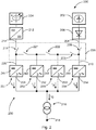
- FIG. 3 shows a regenerative energy generation system 300 with an inverter arrangement 330 according to a further embodiment.
- This regenerative energy generation plant 300 of the Figure 3 differs from the regenerative energy generation system 200 according to FIG Figure 2 essentially only through the use of an output current switching device 360 and a modified transformer 316 including the resulting electrical connection between the output current switching device 360 and the transformer 316.
- the same reference numerals are therefore used for the remaining elements as in FIG Figure 2 and their functionality is also referred to in the explanation of Figure 2 referenced.
- the output current switching device 360 also creates a galvanic separation at the alternating current outputs 251 to 254 of the inverters 231 to 234. This can be achieved in particular by the output coupling switches 361 to 363. By means of these output coupling switches 361 to 363, the inverters 231 to 234 can be connected or disconnected on the output side. For the sake of clarity, the three output coupling switches 361 to 363 are shown open. During operation, however, when all four inverters 231 to 234 are active, only one of the three output coupling switches 361 to 363 is open.
- the output coupling switches 361 to 363 are switched synchronously with the coupling switches 221 to 223 and thereby can be dependent on existing ones Wind energy and, depending on the existing solar radiation, a corresponding number of the inverters 231 to 234 are assigned to the wind energy system 202 or the photovoltaic system 204.
- a wind energy output switch 371 and a photovoltaic output switch 372 are provided. For the sake of clarity, these are also shown in Figure 3 shown open. However, they are preferably closed during operation. In particular, they are switched synchronously with the wind energy switch 309 and the photovoltaic switch 215. It is proposed that the wind energy output switch 371 is switched synchronously with the wind energy switch 209 and the photovoltaic output switch 372 is switched synchronously with the photovoltaic switch 215.
- These four switches can also serve as safety switches, but it is also possible that when there is no solar radiation, especially at night, and a lot of wind energy is available, the photovoltaic switch 215 and the photovoltaic output switch 372 are open and all coupling switches, that is, the first to third coupling switches 221 to 223 and also the first to third output coupling switches 361 to 263 are closed, so that the wind energy system 202 can use all inverters 231 to 234.
- the photovoltaic system 204 it is also possible for the photovoltaic system 204 to use all inverters 231 to 234 in the event of very strong solar irradiation and no wind.
- the output current switching device 360 thus creates a first and a second partial current output 381 and 382, in which a first partial output current I T1 and a second partial output current I T2 are output. These are fed to first and second primary windings 383 and 384 of transformer 316, respectively. They are then superimposed in the transformer 316 and output at the secondary winding 386 as total output current I ' G with a stepped-up voltage. In this way, these two partial output currents I T1 and I T2 can be combined despite galvanic separation.
- the wind energy system 202 with the inverters assigned to it, on the one hand, and the photovoltaic system 204 with the inverters assigned to it, on the other hand can work completely galvanically separated from one another.
- Both the intermediate circuit switching device 236 and the output current switching device 360 can each be designated or designed as a switching matrix.
- Such a switching matrix has many individual switches and by correspondingly closing some switches and opening other switches, corresponding current paths can be formed and desired elements can be electrically connected.
- the operating voltage of the corresponding DC voltage intermediate circuit namely in particular of the second partial intermediate circuit
- the voltage of the photovoltaic system that is required for the MPP method or occurs in the process.
- This voltage can also be referred to as the MPP voltage.
- the intermediate circuit voltage of the wind energy system in particular of a corresponding wind energy installation, is not changed.
- the photovoltaic system does not need an additional galvanically isolated DC power controller, or galvanic isolation can be implemented by the transformer.
- the proposed separation is implemented by a switching matrix, which was explained here as an intermediate circuit switching device 236. Through this switching matrix, the inverters, in the practical implementation it is particularly appropriate power cabinets, can be partially redistributed between the wind energy system and the photovoltaic system.
- the inverters which can also be referred to as converters, are assigned to different feeders, i.e. wind energy system or photovoltaic system, according to the feed-in situation, and are therefore always optimally utilized.
- Galvanic isolation can be implemented on the transformer side, that is to say on the output side towards the transformer 316, by means of a second low-voltage winding, which was shown as the second primary winding 384.
- the secondary winding which can form a medium-voltage winding in the transformer 316, remains unchanged on account of the essentially constant total power.
- a second switching matrix is provided here on the transformer side, namely the output current switching device 360, which distributes the inverters, i.e. in the practical implementation the power cabinets, to the two low-voltage windings, i.e. the first and second primary windings 383 and 384, for galvanic separation.
- the degree of integration can be brought to almost 100% by slightly oversizing, for example by 10% on the transformer and the converter capacity .
- the photovoltaic system 204 can thus be integrated into an existing wind energy system with almost no losses, and this can together form the regenerative energy generation system.
- a photovoltaic system which can be abbreviated as a PV system
- the operating voltage of the PV system must be adapted to the intermediate circuit voltage of the wind energy system, and the PV system must may be galvanically separated from the wind turbine.
- the solution shown here enables this by separating the intermediate circuit of a wind energy installation and assigning the inverters, which can also be referred to as converters, to one of the two intermediate circuits by means of a switching matrix.
Abstract
Die Erfindung betrifft eine Wechselrichteranordnung (230) mit mehreren Wechselrichtern (231-234), wobei jeder Wechselrichter (231-234) einen Gleichspannungszwischenkreis (241-244) und einen Wechselstromausgang (251-254) aufweist, um aus einer Gleichspannung am Gleichspannungszwischenkreis einen Wechselstrom zu erzeugen und an dem Wechselstromausgang auszugeben, und die Wechselrichteranordnung (200) eine Zwischenkreisschaltvorrichtung (236) aufweist, dazu eingerichtet, die Gleichspannungszwischenkreise mehrerer Wechselrichter elektrisch zu verbinden oder zu trennen, um wenigstens einen ersten und einen zweiten Teilzwischenkreis (210, 220) zu bilden, und die Gleichspannungszwischenkreise der Wechselrichter jeweils wahlweise mit dem ersten oder zweiten oder ggf. einem weiteren Teilzwischenkreis galvanisch zu verbinden, wobei der erste und der zweite Teilzwischenkreis und ggf. weitere Teilzwischenkreise galvanisch voneinander getrennt sind.The invention relates to an inverter arrangement (230) with several inverters (231-234), each inverter (231-234) having a direct voltage intermediate circuit (241-244) and an alternating current output (251-254) to convert an alternating current from a direct voltage on the direct voltage intermediate circuit and output at the AC output, and the inverter arrangement (200) has an intermediate circuit switching device (236), configured to electrically connect or disconnect the DC voltage intermediate circuits of several inverters in order to form at least a first and a second intermediate circuit (210, 220) , and to galvanically connect the DC voltage intermediate circuits of the inverters to either the first or second or possibly a further partial intermediate circuit, the first and the second partial intermediate circuit and possibly further partial intermediate circuits being galvanically isolated from one another.
Description
Die vorliegende Erfindung betrifft eine Wechselrichteranordnung mit mehreren Wechselrichtern. Die vorliegende Erfindung betrifft auch eine regenerative Energieerzeugungsanlage mit einer Wechselrichteranordnung. Die vorliegende Erfindung betrifft auch ein Verfahren zum Steuern einer Wechselrichteranordnung und/oder zum Steuern einer regenerativen Erzeugungsanlage.The present invention relates to an inverter arrangement with a plurality of inverters. The present invention also relates to a regenerative power generation system having an inverter arrangement. The present invention also relates to a method for controlling an inverter arrangement and / or for controlling a regenerative generation plant.
Windenergieanlagen und Windparks mit mehreren Windenergieanlagen sind bekannt und können unter dem Begriff Windenergiesystem zusammengefasst werden. Ein solches Windenergiesystem erzeugt elektrische Leistung aus Wind und bereitet diese mittels wenigstens eines Wechselrichters zur Einspeisung in ein elektrisches Versorgungsnetz auf. Photovoltaikanlagen sind ebenfalls bekannt und sie erzeugen elektrische Leistung aus Sonneneinstrahlung und speisen diese so erzeugte elektrische Leistung ebenfalls in ein elektrisches Versorgungsnetz ein. Sonneneinstrahlung kann synonym auch als Sonnenstrahlung, Solareinstrahlung oder Solarstrahlung bezeichnet werden.Wind energy plants and wind parks with several wind energy plants are known and can be summarized under the term wind energy system. Such a wind energy system generates electrical power from wind and prepares it by means of at least one inverter for feeding into an electrical supply network. Photovoltaic systems are also known and they generate electrical power from solar radiation and also feed this electrical power thus generated into an electrical supply network. Solar radiation can also be synonymous with solar radiation, solar radiation or solar radiation.
Wenn ein Windenergiesystem und eine Photovoltaikanlage in örtlicher Nähe zueinander aufgestellt sind, kommt in Betracht, einen gemeinsamen Netzverknüpfungspunkt zu verwenden, an den diese beiden verschiedenen Einspeiser angeschlossen werden. Bspw. kommt in Betracht, dass eine Photovoltaikanlage an einem bereits existierenden Netzverknüpfungspunkt eines Windenergiesystems an das elektrische Versorgungsnetz angeschlossen wird. Ein gemeinsamer Anschluss von einem Windenergiesystem und einer Photovoltaikanlage kann sich besonders durch starke Antikorrelation der Einspeisung aus Windenergie einerseits und Solareinstrahlung andererseits lohnen.If a wind energy system and a photovoltaic system are set up in close proximity to each other, it is possible to use a common network connection point to which these two different feeders are connected. For example, it is possible that a photovoltaic system can be connected to the electrical supply network at an existing network connection point of a wind energy system is connected. A joint connection of a wind energy system and a photovoltaic system can be particularly worthwhile due to the strong anti-correlation between the feed-in from wind energy on the one hand and solar radiation on the other.
Dabei kommt in Betracht, dass der Netzanschlusspunkt und Teile der technischen Infrastruktur gemeinsam genutzt werden, was Kosten einsparen kann.It is possible that the network connection point and parts of the technical infrastructure are used together, which can save costs.
Grundsätzlich sind unterschiedliche Integrationslevel denkbar, nämlich die Folgenden:
- Nur der Netzanschlusspunkt wird von beiden Systemen, also dem Windenergiesystem und der Photovoltaikanlage gemeinsam genutzt, ggf. auch ein Hochspannungstransformator.
- Zusätzlich kommt eine gemeinsame Nutzung einer Mittelspannungsschaltanlage in Betracht.
- Auch eine gemeinsame Nutzung eines Mittelspannungstransformators kommt in Betracht, wobei das Windenergiesystem einerseits und die Photovoltaikanlage andererseits jeweils einen eigenen Wechselrichter auf Niederspannungsseite aufweisen können.
- Es kommt grundsätzlich auch ein gemeinsamer Anschluss an einem Zwischenkreis in Betracht, wobei jedes System, also das Windenergiesystem einerseits und die Photovoltaikanlage andererseits einen eigenen Gleichstromsteller aufweisen, um darüber ihre Energie an den gemeinsamen Gleichspannungszwischenkreis zu übertragen.
- Only the grid connection point is used jointly by both systems, i.e. the wind energy system and the photovoltaic system, and possibly also a high-voltage transformer.
- In addition, shared use of a medium-voltage switchgear is possible.
- Shared use of a medium-voltage transformer is also possible, with the wind energy system on the one hand and the photovoltaic system on the other hand each being able to have its own inverter on the low-voltage side.
- In principle, a common connection to an intermediate circuit is also possible, with each system, i.e. the wind energy system on the one hand and the photovoltaic system on the other, having its own DC power controller in order to transfer its energy to the common DC voltage intermediate circuit.
Soll bspw. eine Photovoltaikanlage an den Gleichspannungszwischenkreis eines Windenergiesystems, also bspw. einer Windenergieanlage, angeschlossen werden, muss die Betriebsspannung der Photovoltaikanlage auf die Zwischenkreisspannung dieser Windenergieanlage angepasst werden und die Photovoltaikanlage muss unter Umständen von der Windenergieanlage galvanisch getrennt werden.If, for example, a photovoltaic system is to be connected to the DC intermediate circuit of a wind energy system, e.g. a wind energy system, the operating voltage of the photovoltaic system must be adapted to the intermediate circuit voltage of this wind energy system and the photovoltaic system may have to be galvanically isolated from the wind energy system.
Die Realisierung solcher Voraussetzungen kann aber kompliziert und kostspielig sein, und daher haben normalerweise regenerative Einspeiser eigene Netzverknüpfungspunkte mit eigener technischer Infrastruktur.However, the realization of such requirements can be complicated and costly, and therefore regenerative feeders usually have their own network connection points with their own technical infrastructure.
Der Erfindung liegt somit die Aufgabe zugrunde, zumindest eines der o.g. Probleme zu adressieren. Insbesondere soll eine möglichst effiziente Lösung geschaffen werden, ein Windenergiesystem zusammen mit einer Photovoltaikanlage an demselben Netzverknüpfungspunkt an ein elektrisches Versorgungsnetz anzuschließen. Zumindest soll zu bisher bekannten Lösungen eine Alternative vorgeschlagen werden.The invention is therefore based on the object of addressing at least one of the above-mentioned problems. In particular, the most efficient possible solution should be created, a To connect the wind energy system together with a photovoltaic system to an electrical supply network at the same network connection point. At least one alternative to previously known solutions should be proposed.
Erfindungsgemäß wird eine Wechselrichteranordnung nach Anspruch 1 vorgeschlagen. Eine solche Wechselrichteranordnung hat somit mehrere Wechselrichter, insbesondere wenigstens drei Wechselrichter. Vorzugsweise sind aber mehr als drei Wechselrichter vorhanden, insbesondere wenigstens 10 und mehr als 10 Wechselrichter.According to the invention, an inverter arrangement according to claim 1 is proposed. Such an inverter arrangement thus has a plurality of inverters, in particular at least three inverters. However, there are preferably more than three inverters, in particular at least 10 and more than 10 inverters.
Jeder Wechselrichter weist einen Gleichspannungszwischenkreis und einen Wechselstromausgang auf, um aus einer Gleichspannung im Gleichspannungszwischenkreis einen Wechselstrom zu erzeugen und an dem Wechselstromausgang auszugeben. Insoweit kann der Gleichspannungszwischenkreis als Eingang angesehen werden, um darüber dem Wechselrichter Leistung bereitzustellen. Aus dem Gleichspannungszwischenkreis wird dann ein Wechselstrom erzeugt und an dem Wechselstromausgang ausgegeben. Insoweit arbeitet der Wechselrichter in bekannter Art und Weise. Die Leistung, die in den Gleichspannungszwischenkreis eingegeben wurde, kann hierdurch mittels des Wechselstroms, der insbesondere als dreiphasiger Wechselstrom erzeugt wird, ausgegeben werden und zusammen mit weiteren Wechselströmen in ein elektrisches Versorgungsnetz eingespeist werden. Das erfolgt insbesondere an einem Netzanschlusspunkt. Es kann auch ein gemeinsamer Transformator für die Wechselrichteranordnung vorgesehen sein, der aus den Wechselströmen dieser Wechselrichter einen gemeinsamen Wechselstrom höherer Spannung erzeugen kann.Each inverter has a direct voltage intermediate circuit and an alternating current output in order to generate an alternating current from a direct voltage in the direct voltage intermediate circuit and to output it at the alternating current output. In this respect, the DC voltage intermediate circuit can be viewed as an input in order to provide power to the inverter. An alternating current is then generated from the direct voltage intermediate circuit and output at the alternating current output. In this respect, the inverter works in a known manner. The power that was input into the DC voltage intermediate circuit can thereby be output by means of the alternating current, which is generated in particular as a three-phase alternating current, and fed into an electrical supply network together with other alternating currents. This takes place in particular at a network connection point. A common transformer can also be provided for the inverter arrangement, which transformer can generate a common alternating current of higher voltage from the alternating currents of these inverters.
Hier können bspw. mehrere Wechselrichter parallel geschaltet sein, was dem Grunde nach als bekannt angenommen werden darf.Here, for example, several inverters can be connected in parallel, which can basically be assumed to be known.
Es wird nun vorgeschlagen, dass die Wechselrichteranordnung eine Zwischenkreisschaltvorrichtung aufweist. Damit werden die Gleichspannungszwischenkreise dieser Wechselrichter elektrisch miteinander verbunden oder voneinander getrennt. Dadurch wird wenigstens ein erster und ein zweiter Teilzwischenkreis gebildet. Sind also bspw. 10 Wechselrichter vorhanden, haben diese jeweils einen Gleichspannungszwischenkreis, sodass zunächst 10 Gleichspannungszwischenkreise vorhanden sind. Von diesen 10 Gleichspannungszwischenkreisen können dann bspw. 7 zu dem ersten Teilzwischenkreis verbunden werden und die verbliebenen 3 zu einem zweiten Teilzwischenkreis.It is now proposed that the inverter arrangement have an intermediate circuit switching device. The DC voltage intermediate circuits of these inverters are thus electrically connected to one another or separated from one another. As a result, at least a first and a second intermediate intermediate circuit are formed. If there are, for example, 10 inverters, they each have a DC voltage intermediate circuit, so that initially 10 DC voltage intermediate circuits are available. Of these 10 DC voltage intermediate circuits, 7, for example, can then be connected to the first partial intermediate circuit and the remaining 3 to a second partial intermediate circuit.
Die Gleichspannungszwischenkreise jeweils eines Teilzwischenkreises sind somit galvanisch miteinander verbunden, wobei aber zwischen den beiden Teilzwischenkreisen eine galvanische Trennung erfolgt. Der erste und zweite Gleichspannungszwischenkreis können dann unabhängig voneinander betrieben werden. Insbesondere können sie unterschiedliche Spannungshöhen aufweisen, was auch beinhaltet, dass der eine Teilzwischenkreis Schwankungen aufweisen kann, die sich von Schwankungen des anderen Teilzwischenkreises, falls der überhaupt Schwankungen hat, unterscheidet, nämlich Schwankungen in der Amplitude der jeweiligen Zwischenkreisspannung.The DC voltage intermediate circuits in each case of a partial intermediate circuit are thus galvanically connected to one another, but with one between the two partial intermediate circuits galvanic separation takes place. The first and second DC voltage intermediate circuit can then be operated independently of one another. In particular, they can have different voltage levels, which also means that one intermediate circuit can have fluctuations that differ from fluctuations in the other intermediate circuit, if any, namely fluctuations in the amplitude of the respective intermediate circuit voltage.
Durch die Zwischenkreisschaltvorrichtung ist es dabei möglich, eine solche Aufteilung in einem ersten und zweiten Teilzwischenkreis variabel zu gestalten. In dem genannten Beispiel von 7 Wechselrichtern für den ersten Teilzwischenkreis und 3 Wechselrichtern für den zweiten Teilzwischenkreis kann die Aufteilung auch verändert werden, in dem bspw. der erste Teilzwischenkreis nach einer weiteren Betätigung der Zwischenkreisschaltvorrichtung 5 Wechselrichter umfasst und der zweite Teilzwischenkreis dann ebenfalls 5 Wechselrichter umfasst.The intermediate circuit switching device makes it possible to design such a division in a first and second intermediate circuit in a variable manner. In the example mentioned of 7 inverters for the first intermediate circuit and 3 inverters for the second intermediate circuit, the division can also be changed in that, for example, the first intermediate circuit comprises 5 inverters after a further actuation of the intermediate circuit switching device and the second intermediate circuit then also comprises 5 inverters .
Eine solche Variabilität ist besonders für die Verwendung der Wechselrichteranordnung für ein regeneratives Erzeugersystem vorgesehen, dass wenigstens ein Windenergiesystem und eine Photovoltaikanlage umfasst. Das Windenergiesystem kann eine Windenergieanlage oder mehrere Windenergieanlagen aufweisen. Die Photovoltaikanlage kann auch aus mehreren einzelnen Photovoltaikeinzelanlagen zusammengesetzt sein. Speist das Windenergiesystem auf den ersten Teilzwischenkreis und die Photovoltaikanlage auf den zweiten Teilzwischenkreis, so kann abhängig der jeweils erzeugten Leistung die Aufteilung der Wechselrichter zwischen erstem und zweitem Teilzwischenkreis vorgenommen werden.Such a variability is provided especially for the use of the inverter arrangement for a regenerative generator system that comprises at least one wind energy system and one photovoltaic system. The wind energy system can have one wind energy installation or several wind energy installations. The photovoltaic system can also be composed of several individual individual photovoltaic systems. If the wind energy system feeds the first intermediate circuit and the photovoltaic system feeds the second intermediate circuit, the inverter can be divided between the first and second intermediate circuit depending on the power generated in each case.
Ist also der Wind stark und die Sonneneinstrahlung schwach, kommt das erste Beispiel in Betracht, bei dem 7 Wechselrichter bzw. ihre Gleichspannungszwischenkreise zu dem ersten Teilzwischenkreis zusammengeschaltet sind und die verbleibenden 3 Wechselrichter bzw. ihre Gleichspannungszwischenkreise zu dem zweiten Teilzwischenkreis zusammengeschaltet sind. Hier wurde besonders erkannt, dass Windenergiesysteme und Photovoltaikanlagen, die in der Nähe zueinander aufgestellt sind, selten gleichzeitig eine hohe Leistung erzeugen. Stattdessen besteht zwischen beiden Systemen häufig eine Antikorrelation, demnach ein wolkenloser Himmel mit starken Sonneneinstrahlung selten bei gleichzeitig starkem Wind auftritt, wohingegen starker Wind häufig zusammen mit erheblicher Wolkenbildung auftritt, so dass dann die Sonneneinstrahlung eher schwach ist.If the wind is strong and the solar radiation is weak, the first example comes into consideration, in which 7 inverters or their DC voltage intermediate circuits are interconnected to form the first partial intermediate circuit and the remaining 3 inverters or their DC voltage intermediate circuits are interconnected to form the second partial intermediate circuit. It was particularly recognized here that wind energy systems and photovoltaic systems that are set up in close proximity to one another rarely generate a high output at the same time. Instead, there is often an anti-correlation between the two systems, according to which a cloudless sky with strong solar radiation rarely occurs with strong winds at the same time, whereas strong wind often occurs together with considerable cloud formation, so that the solar radiation is then rather weak.
Es wurde auch erkannt, dass moderne Windenergieanlagen so arbeiten, dass elektrische Leistung mit einem Synchrongenerator erzeugt, gleichgerichtet und dann als gleichgerichteter Strom einem Gleichspannungszwischenkreis zugeführt wird. Ebenfalls wurde erkannt, dass Photovoltaikanlagen auch einen Gleichstrom erzeugen und einen Gleichspannungszwischenkreis zur Verfügung stellen. In beiden Fällen kann dann ausgehend von dem jeweiligen Gleichspannungszwischenkreis mittels eines Wechselrichters ein Wechselstrom erzeugt werden.It was also recognized that modern wind turbines work in such a way that electrical power is generated with a synchronous generator, rectified and then fed as a rectified current to a DC voltage intermediate circuit. It was also recognized that photovoltaic systems also generate a direct current and provide a direct voltage intermediate circuit. In both cases, starting from the respective DC voltage intermediate circuit, an alternating current can be generated by means of an inverter.
Trotz ähnlicher Spannungsamplituden beider Gleichspannungszwischenkreise können sich die Spannungen und/oder Spannungsverläufe solcher Gleichspannungszwischenkreise dennoch unterscheiden. Besonders kommt bei einer Photovoltaikanlage in Betracht, dass ihr Arbeitspunkt über die Spannungshöhe am Gleichspannungszwischenkreis eingestellt wird oder zumindest die Spannungshöhe am Gleichspannungszwischenkreis von einer Gleichspannung abhängt, die zum Einstellen des Arbeitspunktes der Photovoltaikanlage gewählt wurde. Hier liegt besonders die Erkenntnis zugrunde, dass eine Photovoltaikanlage ständig ihren Arbeitspunkt gemäß eines sog. MPP-Tracking-Verfahrens einstellt. Ein solches Verfahren bezeichnet die technische Vorgehensweise, demnach quasi ständig nach einem maximalen Arbeitspunkt gesucht wird, also einem Arbeitspunkt, bei dem maximale Leistung erzeugt werden kann. Besonders kann das Auswirkungen auf den Spannungsverlauf im entsprechenden Gleichspannungszwischenkreis des nachgelagerten Wechselrichters haben. Entsprechend ergibt sich dazu ein Unterschied zu einem Gleichspannungszwischenkreis eines Wechselrichters, der von einem Generator einer Windenergieanlage gespeist wird.Despite the similar voltage amplitudes of the two DC voltage intermediate circuits, the voltages and / or voltage profiles of such DC voltage intermediate circuits can nevertheless differ. In the case of a photovoltaic system, it is particularly important that its operating point is set via the voltage level on the DC voltage intermediate circuit or at least the voltage level on the DC voltage intermediate circuit depends on a DC voltage that was selected for setting the operating point of the photovoltaic system. This is based in particular on the knowledge that a photovoltaic system constantly adjusts its operating point in accordance with a so-called MPP tracking method. Such a method refers to the technical procedure, according to which a maximum working point is sought, so to speak, an operating point at which maximum power can be generated. In particular, this can have an impact on the voltage curve in the corresponding DC voltage intermediate circuit of the downstream inverter. Correspondingly, there is a difference to a DC voltage intermediate circuit of an inverter which is fed by a generator of a wind energy installation.
Es wurde auch erkannt, dass der einzelne Wechselrichter gegen solche unterschiedlichen Spannungshöhen tolerant ist. Grundsätzlich erzeugt ein Wechselrichter aus der Gleichspannung eines Gleichspannungszwischenkreises einen Wechselstrom mit einer gewissen Wechselspannungsamplitude. Durch diese Wechselspannungsamplitude ist auch der Spannungsbereich für den Gleichspannungszwischenkreis festgelegt. Solange die Spannungshöhe des Gleichspannungszwischenkreises aber innerhalb dieses festgelegten Bereichs ist, stellen Spannungsschwankungen, also Spannungsschwankungen innerhalb dieses Bereichs, kein Problem für den Wechselrichter dar, und der Wechselrichter kann sich auf solche Variationen einstellen und bspw. durch ein angepasstes Pulsverhalten reagieren.It was also recognized that the individual inverter is tolerant of such different voltage levels. Basically, an inverter generates an alternating current with a certain alternating voltage amplitude from the direct voltage of a direct voltage intermediate circuit. This AC voltage amplitude also defines the voltage range for the DC voltage intermediate circuit. As long as the voltage level of the DC link is within this specified range, however, voltage fluctuations, i.e. voltage fluctuations within this range, do not pose a problem for the inverter, and the inverter can adapt to such variations and react, for example, with an adapted pulse behavior.
Insbesondere wird vorgeschlagen, dass jeder Wechselrichter mit einem Toleranzbandverfahren arbeitet. Bei einem solchen Toleranzbandverfahren wird für den zu erzeugenden Ausgangsstrom ein Toleranzband vorgegeben, in dem sich der erzeugte Strom befinden soll. Stößt der erzeugte Strom an eine der beiden Toleranzbandgrenzen, die nämlich das Toleranzband definieren, so wird in dem Wechselrichter entsprechend geschaltet. Dadurch wird bei einem Toleranzbandverfahren das entsprechende Pulsmuster generiert. Das Toleranzbandverfahren ist insoweit eine Regelung, bei der das Schaltverhalten des Wechselrichters immer abhängig von dem erzeugten Strom und zwar immer bezogen auf die Augenblickswerte, nachgeführt wird.In particular, it is proposed that each inverter work with a tolerance band method. In such a tolerance band method, a tolerance band is specified for the output current to be generated, in which the generated current is located should be located. If the generated current hits one of the two tolerance band limits, which namely define the tolerance band, the inverter is switched accordingly. As a result, the corresponding pulse pattern is generated in a tolerance band method. To this extent, the tolerance band method is a regulation in which the switching behavior of the inverter is always tracked as a function of the current generated and always in relation to the instantaneous values.
Dazu wurde erkannt, dass dann, wenn sich die Spannung im Gleichspannungszwischenkreis verändert sich dies aufgrund der unmittelbaren und sofortigen Messung des erzeugten Ausgangsstroms sofort im Schaltverhalten wiederspiegelt, der erzeugte Strom aber weiterhin so erzeugt wird, dass er im Toleranzband liegt.For this purpose, it was recognized that if the voltage in the DC link changes, this is immediately reflected in the switching behavior due to the direct and immediate measurement of the output current generated, but the current generated continues to be generated in such a way that it is within the tolerance band.
Davon ausgehend wurde somit erkannt, dass die Gleichspannungszwischenkreis jedes Wechselrichters sowohl für den Betrieb mit einem Windenergiesystem als auch für den Betrieb mit einer Photovoltaikanlage geeignet sind. Die Unterschiede, die sich zwischen dem Windenergiesystem und der Photovoltaikanlage ergeben, sind allerdings insoweit zu berücksichtigen, als dass die jeweils erzeugten Gleichspannungen galvanisch voneinander getrennt sein sollten. Das wird durch die Zwischenkreisschaltvorrichtung erreicht. Durch sie kann auch erreicht werden, dass bedarfsabhängig, nämlich abhängig davon, wieviel Windleistung aktuell verfügbar ist im Vergleich zu wieviel Leistung aus Sonneneinstrahlung aktuell verfügbar ist, entsprechend mehr oder weniger Wechselrichter mit dem Windenergiesystem verbunden werden und entsprechend mehr oder weniger viele Wechselrichter mit der Photovoltaikanlage verbunden werden.On the basis of this, it was recognized that the DC voltage intermediate circuit of each inverter is suitable both for operation with a wind energy system and for operation with a photovoltaic system. The differences that arise between the wind energy system and the photovoltaic system must, however, be taken into account insofar as the DC voltages generated in each case should be galvanically separated from one another. This is achieved by the intermediate circuit switching device. They can also ensure that, depending on requirements, i.e. depending on how much wind power is currently available compared to how much power from solar radiation is currently available, more or fewer inverters are connected to the wind energy system and correspondingly more or less inverters are connected to the photovoltaic system get connected.
Durch die Zwischenkreisschaltvorrichtung kann somit eine leistungsabhängige Aufteilung zwischen Windenergiesystem einerseits und Photovoltaikanlage andererseits auf einfache Art und Weise geschaffen werden. Allein das variable Bilden des ersten und zweiten Teilzwischenkreises schafft die Möglichkeit, eine entsprechende Wechselrichterkapazität für das Windenergiesystem bzw. die Photovoltaikanlage bereitzustellen.By means of the intermediate circuit switching device, a power-dependent division between the wind energy system on the one hand and the photovoltaic system on the other hand can thus be created in a simple manner. The variable formation of the first and second intermediate circuit alone creates the possibility of providing a corresponding inverter capacity for the wind energy system or the photovoltaic system.
Somit wird vorgeschlagen, die Gleichspannungszwischenkreise der Wechselrichter in einen ersten und einen zweiten Teilzwischenkreis aufzuteilen. Als Erweiterung kommt aber auch in Betracht, dass über einen dritten Teilzwischenkreis ein Energiespeicher, besonders eine Batterie, mit eingebunden werden kann. Außerdem kommt in Betracht, auch noch einen vierten Teilzwischenkreis auf die gleiche Art und Weise zu schaffen, wenn bspw. außerdem über den Gleichspannungszwischenkreis ein Verbraucher versorgt werden soll. Insoweit kommt auch in Betracht, dass jeder Wechselrichter bidirektional arbeitet, also nicht nur aus seinem Gleichspannungszwischenkreis einen Wechselstrom erzeugt, sondern auch einen Wechselstrom in einen Gleichstrom wandeln und in den Gleichspannungszwischenkreis einspeisen kann. Das kommt dann in Betracht, wenn besonders für eine Netzstützungsmaßnahme elektrische Leistung aus dem elektrischen Versorgungsnetz entnommen werden soll.It is therefore proposed to divide the DC voltage intermediate circuits of the inverters into a first and a second partial intermediate circuit. As an extension, however, it can also be considered that an energy store, in particular a battery, can also be integrated via a third intermediate intermediate circuit. It is also possible to create a fourth intermediate circuit in the same way if, for example, a consumer is to be supplied via the DC voltage intermediate circuit. In this respect, it is also possible that each inverter works bidirectionally, i.e. not just an alternating current from its DC voltage intermediate circuit generated, but can also convert an alternating current into a direct current and feed it into the DC voltage intermediate circuit. This comes into consideration when electrical power is to be drawn from the electrical supply network, especially for a network support measure.
Gemäß einer Variante kann aber vorgesehen sein, dass nur insgesamt drei Teilzwischenkreise verwendet werden und der genannte Energiespeicher kann somit als zusätzlicher Erzeuger und alternativ zusätzlicher Verbraucher verwendet werden und beides kann an einem Teilzwischenkreis, insbesondere an dem genannten dritten Teilzwischenkreis realisiert werden.According to one variant, however, it can be provided that only a total of three intermediate intermediate circuits are used and the aforementioned energy store can thus be used as an additional generator and, alternatively, additional consumer, and both can be implemented on a intermediate intermediate circuit, in particular on the third intermediate intermediate circuit mentioned.
Gemäß einer Ausführungsform wird vorgeschlagen, dass Wechselrichter, deren Gleichspannungszwischenkreis mit dem ersten Teilzwischenkreis verbunden sind, zu einer Wechselrichterteilanordnung zusammengefasst werden, um einen ersten Teilwechselstrom zu erzeugen, und dass Wechselrichter, deren Gleichspannungszwischenkreis mit dem zweiten Teilzwischenkreis verbunden sind, zu einer zweiten Wechselrichterteilanordnung zusammengefasst werden, um einen zweiten Teilwechselstrom zu erzeugen, wobei der erste und zweite Teilwechselstrom zum Einspeisen in ein elektrisches Versorgungsnetz zu einem Gesamtwechselstrom zusammengeführt werden und wenigstens mittels der Zwischenkreisschaltvorrichtung Wechselrichter wahlweise der ersten oder zweiten Wechselrichteranordnung zugeordnet werden können.According to one embodiment, it is proposed that inverters whose DC voltage intermediate circuit are connected to the first partial intermediate circuit are combined to form an inverter subassembly in order to generate a first partial alternating current, and that inverters whose DC voltage intermediate circuit are connected to the second partial intermediate circuit are combined to form a second inverter subassembly to generate a second partial alternating current, wherein the first and second partial alternating currents are combined into a total alternating current for feeding into an electrical supply network and inverters can optionally be assigned to the first or second inverter arrangement at least by means of the intermediate circuit switching device.
Diese Ausführungsform realisiert noch besser die vorstehend erläuterten Möglichkeiten, die vielen Wechselrichter bedarfsabhängig zwischen einem Windenergiesystem und einer Photovoltaikanlage aufzuteilen. Vorzugsweise werden immer entsprechend so viele Wechselrichter zu einer ersten Wechselrichterteilanordnung zusammengefasst, wie zum Erzeugen und Einspeisen eines Wechselstroms für das Windenergiesystem benötigt wird, wohingegen entsprechend viele bzw. wenige Wechselrichter zur zweiten Wechselrichterteilanordnung zusammengefasst werden, um die von der Photovoltaikanlage erzeugte Leistung in einen Wechselstrom zu wandeln und zum Einspeisen in das elektrische Versorgungsnetz vorzubereiten.This embodiment realizes even better the possibilities explained above of dividing the many inverters between a wind energy system and a photovoltaic system as required. Preferably, as many inverters are always combined into a first inverter sub-arrangement as is required to generate and feed an alternating current for the wind energy system, whereas a corresponding number or few inverters are combined in the second inverter sub-arrangement in order to convert the power generated by the photovoltaic system into an alternating current convert and prepare for feeding into the electrical supply network.
Die Zuordnung kann wahlweise erfolgen und das erfolgt besonders abhängig von der der ersten bzw. zweiten Wechselrichterteilanordnung zugeführten oder zur Verfügung stehenden, einzuspeisenden elektrischen Leistung.The assignment can be made optionally, and this is particularly dependent on the electrical power to be fed in or available to the first or second inverter sub-arrangement.
Gemäß einer Ausführungsform wird vorgeschlagen, dass die Wechselstromausgänge der Wechselrichter, zumindest die Wechselstromausgänge von Wechselrichtern unterschiedlicher Wechselrichterteilanordnungen, galvanisch voneinander getrennt sind. Dadurch kann eine Betriebssicherheit gewährleistet werden und/oder es können Querströme oder Kreisströme vermieden werden die andernfalls, bspw. über ein Erdpotenzial, auftreten könnten. Dadurch, dass die Wechselstromausgänge galvanisch untereinander getrennt sind, kann ein eigenständiges Arbeiten der Wechselrichter voneinander gewährleistet werden. Es kann aber ausreichen, dass nur eine galvanische Trennung zwischen den Wechselrichtern der ersten Wechselrichteranordnung einerseits und den Wechselrichtern der zweiten Wechselrichteranordnung andererseits gewährleistet wird. Es kommt aber in Betracht, dass, bspw. durch einen einzelnen Transformator am Ausgang jedes Wechselrichters, jeder Wechselrichter an seinem Wechselstromausgang von allen anderen Wechselrichtern bzw. mehreren Wechselstromausgängen galvanisch getrennt ist. Es kommt auch in Betracht, dass ein Transformator eingangsseitig, bzw. an seiner Primärseite, eine Wicklung für jeden Wechselrichter aufweist. Beide Varianten hätten den Vorteil, dass bei einer Veränderung der Zuordnung der Wechselrichter zur ersten und/oder zweiten Wechselrichteranordnung eine solche galvanische Trennung nicht angepasst zu werden braucht.According to one embodiment, it is proposed that the AC outputs of the inverters, at least the AC outputs of inverters, are different Inverter sub-assemblies, are galvanically separated from each other. In this way, operational safety can be guaranteed and / or cross currents or circular currents can be avoided which could otherwise occur, for example via an earth potential. The fact that the AC outputs are galvanically separated from one another means that the inverters can work independently from one another. However, it can be sufficient that only a galvanic separation between the inverters of the first inverter arrangement on the one hand and the inverters of the second inverter arrangement on the other hand is ensured. However, it comes into consideration that, for example, by means of a single transformer at the output of each inverter, each inverter is galvanically isolated at its AC output from all other inverters or from several AC outputs. It is also possible that a transformer has one winding for each inverter on the input side or on its primary side. Both variants have the advantage that if the assignment of the inverters to the first and / or second inverter arrangement is changed, such a galvanic separation does not need to be adapted.
Besonders die Variante, einen Transformator mit jeweils einer Wicklung für jeden Wechselrichter, nämlich für jeden Wechselrichterausgang, vorzusehen, kann eine kostengünstige Lösung sein, bei der nämlich jede Wicklung nur auf den jeweiligen Wechselrichter ausgelegt zu sein braucht. Das hat gegenüber der Variante, nur eine galvanische Trennung zwischen den Wechselrichtern der ersten Wechselrichteranordnung einerseits und den Wechselrichtern der zweiten Wechselrichteranordnung andererseits vorzusehen, den Vorteil, dass der Transformator eingangsseitig gezielt dimensioniert werden kann.In particular, the variant of providing a transformer with one winding for each inverter, namely for each inverter output, can be a cost-effective solution in which each winding only needs to be designed for the respective inverter. Compared to the variant of only providing galvanic isolation between the inverters of the first inverter arrangement on the one hand and the inverters of the second inverter arrangement on the other hand, this has the advantage that the transformer can be specifically dimensioned on the input side.
Für eine galvanische Trennung nur zwischen den Wechselrichtern der ersten Wechselrichteranordnung einerseits und den Wechselrichtern der zweiten Wechselrichteranordnung andererseits kann ein Transformator mit eingangsseitig nur zwei getrennten Wicklungen vorgesehen sein. Ein Transformator mit solchen zwei eingangsseitigen Wicklungen ist mit vergleichsweise geringem Aufwand herstellbar, die eingangsseitigen Wicklungen müssen aber vorsorglich groß dimensioniert sein, weil die Größe der ersten und zweiten Wechselrichteranordnung variieren kann. Andererseits kann das Vorsehen besonders einer entsprechenden Schalteranordnung, um eine galvanische Trennung zwischen den einzelnen Wechselrichterteilanordnungen zu gewährleisten, konstruktiv einfach und mit geringem Kostenaufwand umgesetzt werden.For a galvanic isolation only between the inverters of the first inverter arrangement on the one hand and the inverters of the second inverter arrangement on the other hand, a transformer with only two separate windings on the input side can be provided. A transformer with such two input-side windings can be manufactured with comparatively little effort, but the input-side windings must, as a precaution, be large because the size of the first and second inverter arrangement can vary. On the other hand, the provision in particular of a corresponding switch arrangement in order to ensure galvanic separation between the individual inverter sub-arrangements can be implemented in a structurally simple manner and at low cost.
Besonders wird vorgeschlagen, dass die Wechselrichter, zumindest die Wechselrichter der unterschiedlichen Wechselrichteranordnungen, so an einen Transformator mit wenigstens zwei Primärwicklungen angeschlossen sind, dass ihre Wechselströme in dem Transformator zu einem gemeinsamen Wechselstrom überlagert werden. Hier kommt besonders in Betracht, dass lediglich eine galvanische Trennung zwischen den beiden Wechselrichterteilanordnungen vorgesehen ist. Im Ergebnis können dann zwei Teilwechselströme ausgegeben werden, die zueinander galvanisch getrennt sind. Diese können dann in eine erste und zweite Primärwicklung eines Transformators eingegeben werden und in diesem Transformator überlagert werden. Der Transformator kann dann eine einzelne sekundärseitige Wicklung und damit einen einzigen sekundärseitigen Ausgang aufweisen, an dem dann ein Gesamtstrom erzeugt bzw. ausgegeben werden kann, um diesen dann in das elektrische Versorgungsnetz einzuspeisen.In particular, it is proposed that the inverters, at least the inverters of the different inverter arrangements, be connected to a transformer with at least two primary windings are connected so that their alternating currents are superimposed in the transformer to form a common alternating current. It is particularly important here that only a galvanic separation is provided between the two inverter sub-assemblies. As a result, two partial alternating currents can then be output that are galvanically isolated from one another. These can then be input into a first and second primary winding of a transformer and superimposed in this transformer. The transformer can then have a single secondary-side winding and thus a single secondary-side output, at which a total current can then be generated or output in order to then feed it into the electrical supply network.
Grundsätzlich kommt auch in Betracht, dass ein solcher Transformator mehr als zwei Primärwicklungen aufweist, was allerdings technisch aufwendig sein kann.In principle, it is also possible that such a transformer has more than two primary windings, which, however, can be technically complex.
Gemäß einer Ausgestaltung wird vorgeschlagen, dass die Wechselrichteranordnung eine Ausgangsstromschaltvorrichtung aufweist, die dazu eingerichtet ist, Wechselstromausgänge mehrerer Wechselrichter elektrisch zu verbinden oder zu trennen, um einen ersten und einen zweiten Teilstromausgang zu bilden, und die Wechselstromausgänge der Wechselrichter jeweils wahlweise mit dem ersten oder zweiten Teilstromausgang galvanisch zu verbinden, wobei der erste und der zweite Teilstromausgang durch die Ausgangsstromschaltvorrichtung galvanisch voneinander getrennt sind. Insbesondere ist vorgesehen, dass die Ausgangsstromschaltvorrichtung mit der Zwischenkreisschaltvorrichtung synchronisiert ist, also dass der erste Teilstromausgang der ersten Wechselrichteranordnung zugeordnet ist und der zweite Teilstromausgang der zweiten Wechselrichterteilanordnung zugeordnet ist.According to one embodiment, it is proposed that the inverter arrangement has an output current switching device which is set up to electrically connect or disconnect AC outputs of several inverters in order to form a first and a second partial current output, and the AC outputs of the inverters each optionally with the first or second To connect partial current output galvanically, the first and the second partial current output are galvanically separated from each other by the output current switching device. In particular, it is provided that the output current switching device is synchronized with the intermediate circuit switching device, that is, that the first partial current output is assigned to the first inverter arrangement and the second partial current output is assigned to the second inverter subassembly.
Vorzugsweise ist auch hier der beschriebene Transformator mit wenigstens zwei Primärwicklungen vorgesehen, wobei der erste Teilstromausgang der ersten Primärwicklung und der zweite Teilstromausgang mit der zweiten Primärwicklung verbunden sind, um die beiden Teilausgangsströme erst in dem Transformator zu überlagern.The transformer described is preferably also provided here with at least two primary windings, the first partial current output of the first primary winding and the second partial current output being connected to the second primary winding in order to superimpose the two partial output currents only in the transformer.
Die beschriebene galvanische Trennung der Wechselstromausgänge bzw. die beschriebene galvanische Zusammenfassung der Wechselstromausgänge kann durch diese Ausgangsstromschaltvorrichtung erreicht werden. Durch die vorgeschlagene Synchronisierung zwischen der Ausgangsstromschaltvorrichtung und der Zwischenkreisschaltvorrichtung werden Wechselrichter sowohl an ihrem Gleichspannungszwischenkreis als auch an ihrem Wechselstromausgang einer der Wechselrichteilanordnungen zugeordnet. In beiden Fällen kann eine galvanische Verbindung zu der Wechselrichterteilanordnung hergestellt werden, zu der sie neu zugeordnet werden, und eine galvanische Trennung zu der Wechselrichterteilanordnung hergestellt werden, zu der der Wechselrichter zuvor zugeordnet war.The described galvanic separation of the alternating current outputs or the described galvanic combination of the alternating current outputs can be achieved by this output current switching device. As a result of the proposed synchronization between the output current switching device and the intermediate circuit switching device, inverters are assigned to one of the inverter subassemblies both at their DC voltage intermediate circuit and at their AC output. In both cases, a galvanic connection to the inverter subassembly to which they are reassigned, and a galvanic separation to the inverter subassembly to which the inverter was previously assigned.
Grundsätzlich kommt auch hier in Betracht, dass eine dritte und noch weitere Wechselrichterteilanordnungen vorgesehen sind und auch diese mittels einer entsprechenden Ausgangsstromschaltvorrichtung im Bereich ihrer Wechselstromausgänge entsprechend geschaltet werden.In principle, it is also possible here that a third and further inverter sub-assemblies are provided and that these are also switched accordingly in the area of their alternating current outputs by means of a corresponding output current switching device.
Gemäß einer Ausgestaltung wird vorgeschlagen, dass der erste Teilzwischenkreis einen Windenergieanschluss aufweist, zum Verbinden mit einem Windenergiesystem, um darüber von dem Windenergiesystem erzeugte elektrische Leistung zu erhalten, und dass der zweite Teilzwischenkreis einen Photovoltaikanschluss aufweist, zum Verbinden mit einer Photovoltaikanlage, um darüber von der Photovoltaikanlage erzeugte elektrische Leistung zu erhalten. Dazu wird vorgeschlagen, dass die Wechselrichteranordnung dazu vorbereitet ist, dass sich die Zwischenkreisspannung zwischen dem ersten und zweiten Teilzwischenkreis unterscheiden. Insbesondere wird vorgeschlagen, dass an dem zweiten Teilzwischenkreis eine Zwischenkreisspannung in Abhängigkeit eines Arbeitspunktes der Photovoltaikanlage eingestellt wird.According to one embodiment, it is proposed that the first intermediate circuit has a wind energy connection for connecting to a wind energy system in order to receive electrical power generated by the wind energy system, and that the second intermediate circuit has a photovoltaic connection for connecting to a photovoltaic system in order to use it from the Photovoltaic system to obtain electrical power generated. To this end, it is proposed that the inverter arrangement be prepared for the intermediate circuit voltage to differ between the first and second partial intermediate circuits. In particular, it is proposed that an intermediate circuit voltage be set on the second partial intermediate circuit as a function of an operating point of the photovoltaic system.
Über diese beiden Anschlüsse, also den Windenergieanschluss und den Photovoltaikanschluss kann die Wechselrichteranordnung somit gleichzeitig mit einem Windenergiesystem und einer Photovoltaikanlage verbunden werden. Die Wechselrichteranordnung kann dann gleichzeitig die Leistung beider Energieerzeuger in das elektrische Versorgungsnetz einspeisen. Als Windenergiesystem wird hier eine einzelne Windenergieanlage oder mehrere Windenergieanlagen bezeichnet, die über denselben Netzanschlusspunkt in das elektrische Versorgungsnetz einspeisen. Hierunter kann auch ein Windpark fallen.Via these two connections, that is to say the wind energy connection and the photovoltaic connection, the inverter arrangement can thus be connected to a wind energy system and a photovoltaic system at the same time. The inverter arrangement can then feed the power of both energy producers into the electrical supply network at the same time. A single wind energy installation or several wind energy installations which feed into the electrical supply network via the same network connection point are referred to here as a wind energy system. This can also include a wind farm.
Die Zwischenkreisspannungen können sich dabei zwischen dem ersten und zweiten Teilzwischenkreis unterscheiden und das kann besonders dadurch erreicht werden, dass die Teilzwischenkreise galvanisch voneinander getrennt sind. Darüber hinaus wird vorgeschlagen, dass die Wechselrichter gegenüber Variationen der Zwischenkreisspannungen an ihrem Gleichspannungszwischenkreis tolerant sind. Dadurch kann die Wechselrichteranordnung dazu vorbereitet sein, dass sich die Zwischenkreisspannungen zwischen dem ersten und zweiten Teilzwischenkreis unterscheiden. Die genannte galvanische Trennung lässt solche Unterschiede zu und die Wechselrichter sind gegenüber solchen Spannungsschwankungen tolerant. Eine Möglichkeit, dass ein Wechselrichter gegenüber Spannungsschwankungen am Gleichspannungszwischenkreis tolerant ist, kann dadurch realisiert werden, dass der Wechselrichter nach dem Toleranzbandverfahren arbeitet und/oder die Wechselrichter so dimensioniert sind, dass auch bei einer Spannungsvariabilität immer ein ausreichend großer Strom ins Netz eingespeist werden kann.The intermediate circuit voltages can differ between the first and second intermediate circuit elements and this can be achieved in particular by the intermediate circuit elements being galvanically separated from one another. It is also proposed that the inverters be tolerant of variations in the intermediate circuit voltages on their DC voltage intermediate circuit. As a result, the inverter arrangement can be prepared so that the intermediate circuit voltages differ between the first and second intermediate circuit elements. The aforementioned galvanic separation allows such differences and the inverters are tolerant of such voltage fluctuations. One possibility for an inverter to be tolerant of voltage fluctuations on the DC voltage intermediate circuit can thereby be realized that the inverter works according to the tolerance band method and / or the inverters are dimensioned in such a way that a sufficiently large current can always be fed into the grid even with a voltage variability.
Vorzugsweise wird dadurch, dass die beiden Zwischenkreisspannung sich voneinander unterscheiden können, ermöglicht, dass der zweite Teilzwischenkreis seine Zwischenkreisspannung so einstellt, dass dadurch ein gewünschter Arbeitspunkt in der Photovoltaikanlage gefunden wird. Insbesondere kann mittels der Zwischenkreisspannung des zweiten Teilzwischenkreises ein sog. MPP-Tracking-Verfahren für die Photovoltaikanlage durchgeführt werden. Es kommt aber auch in Betracht, dass dieses MPP-Tracking-Verfahren an der Photovoltaikanlage selbst und nicht in dem zweiten Teilzwischenkreis durchgeführt wird, dass aber resultierende Spannungsvariationen an der Photovoltaikanlage auch zu Variationen der Zwischenkreisspannung an dem zweiten Teilzwischenkreis führen.The fact that the two intermediate circuit voltages can differ from one another preferably makes it possible for the second sub-intermediate circuit to set its intermediate circuit voltage in such a way that a desired operating point is found in the photovoltaic system. In particular, a so-called MPP tracking method for the photovoltaic system can be carried out by means of the intermediate circuit voltage of the second sub-intermediate circuit. However, it is also possible that this MPP tracking method is carried out on the photovoltaic system itself and not in the second intermediate circuit, but that resulting voltage variations on the photovoltaic system also lead to variations in the intermediate circuit voltage on the second intermediate circuit.
Gemäß einer Variante weist die Photovoltaikanlage einen zusätzlichen Zwischenkreis auf, der über einen Gleichstromsteller, der auch als DC/DC-Wandler bezeichnet wird, mit dem zweiten Teilzwischenkreis verbunden ist. Das hat den Vorteil, dass die Zwischenkreisspannung am zweiten Teilzwischenkreis entsprechend der Netzspannung und des Blindleistungsbedarfs eingestellt werden kann. Dabei kann auch für diese Variante die galvanische Trennung zwischen dem ersten und zweiten Teilzwischenkreis gewährleistet werden. Dadurch kann der DC/DC-Wandler kostengünstig ohne galvanische Trennung ausgebildet sein.According to one variant, the photovoltaic system has an additional intermediate circuit, which is connected to the second intermediate circuit via a DC converter, which is also referred to as a DC / DC converter. This has the advantage that the intermediate circuit voltage on the second partial intermediate circuit can be set according to the line voltage and the reactive power requirement. Galvanic isolation between the first and second intermediate circuit can also be ensured for this variant. As a result, the DC / DC converter can be designed cost-effectively without galvanic isolation.
Gemäß einer Ausführungsform wird vorgeschlagen, dass das Windenergiesystem und die Photovoltaikanlage, die nämlich an dem Windenergieanschluss bzw. dem Photovoltaikanschluss mit der Wechselrichteranordnung verbunden werden, jeweils durch eine Nennleistung gekennzeichnet sind. Eine solche Kennzeichnung durch eine Nennleistung ist üblich und eine solche Nennleistung kann regelmäßig auch eine Maximalleistung des jeweiligen Systems darstellen, die in einem Normalbetrieb nicht überschritten werden soll. Diese beiden Nennleistungen können zwar theoretisch gleich sein, meist werden sie aber unterschiedlich sein, weil das Windenergiesystem und die Photovoltaikanlage meist unabhängig voneinander ausgelegt werden. Vorzugsweise wird davon ausgegangen, dass die Nennleistung der Photovoltaikanlage kleiner als die des Windenergiesystems ist.According to one embodiment, it is proposed that the wind energy system and the photovoltaic system, which are namely connected to the inverter arrangement at the wind energy connection or the photovoltaic connection, are each characterized by a nominal power. Such a designation by a nominal power is common and such a nominal power can regularly also represent a maximum power of the respective system, which should not be exceeded in normal operation. Although these two nominal powers can theoretically be the same, they will usually be different because the wind energy system and the photovoltaic system are usually designed independently of one another. It is preferably assumed that the nominal power of the photovoltaic system is less than that of the wind energy system.
Davon ausgehend wird dann vorgeschlagen, dass die Wechselrichteranordnung eine Nennleistung aufweist, die der Nennleistung des Windenergiesystems zzgl. einer Reserveleistung entspricht. Die Wechselrichteranordnung wird also basierend auf der Nennleistung des Windenergiesystems ausgelegt. Das bedeutet besonders, dass jeder Wechselrichter eine Nennleistung aufweist, die er im Normalbetrieb maximal von Gleichstrom in Wechselstrom umwandeln kann, wobei die Nennleistung der Wechselrichteranordnung dann die Summe aller Nennleistungen der Wechselrichter ist. Vorzugsweise sind alle Wechselrichter gleich dimensioniert und die Nennleistung der Wechselrichteranordnung entspricht dann der Nennleistung eines Wechselrichters multipliziert mit der Anzahl vorhandener Wechselrichter.On this basis, it is then proposed that the inverter arrangement have a nominal power which corresponds to the nominal power of the wind energy system plus a reserve power. The inverter arrangement is therefore based on the nominal power of the wind energy system. In particular, this means that each inverter has a nominal power which it can convert from direct current to alternating current during normal operation, the nominal power of the inverter arrangement then being the sum of all nominal powers of the inverters. All inverters are preferably dimensioned identically and the nominal power of the inverter arrangement then corresponds to the nominal power of an inverter multiplied by the number of inverters present.
Die Auslegung der Wechselrichteranordnung kann auch die Auslegung eines Transformators, insbesondere Hochspannungstransformators beinhalten, der ebenfalls auf die Nennleistung der Wechselrichteranordnung ausgelegt wird.The design of the inverter arrangement can also include the design of a transformer, in particular a high-voltage transformer, which is also designed for the nominal power of the inverter arrangement.
Dazu wird somit vorgeschlagen, dass die Nennleistung der Wechselrichteranordnung der Nennleistung des Windenergiesystems zzgl. einer Reserveleistung entspricht. Die Reserveleistung kann auch den Wert 0 betragen, weist vorzugsweise aber einen größeren Wert auf, der bis zu 20 % oder zumindest bis zu 10 % der Nennleistung des Windenergiesystems betragen kann. Somit wird die Wechselrichteranordnung nur geringfügig größer als das Windenergiesystem ausgelegt.For this purpose, it is therefore proposed that the nominal power of the inverter arrangement corresponds to the nominal power of the wind energy system plus a reserve power. The reserve power can also have the value 0, but preferably has a larger value which can be up to 20% or at least up to 10% of the nominal power of the wind energy system. The inverter arrangement is therefore designed to be only slightly larger than the wind energy system.
Dem liegt besonders der Gedanke zugrunde, dass eine solche Auslegung ausreichen kann und es nicht erforderlich ist, die Nennleistung der Wechselrichteranordnung auf die Summe der Nennleistungen des Windenergiesystems und der Photovoltaikanlage auszulegen.This is based in particular on the idea that such a design can be sufficient and it is not necessary to design the nominal power of the inverter arrangement to be the sum of the nominal powers of the wind energy system and the photovoltaic system.
Durch die erkannte Antikorrelation zwischen verfügbarer Windleistung und verfügbarer Sonnenleistung wurde auch erkannt, dass eine Auslegung der Wechselrichteranordnung auf die Nennleistung des Windenergiesystems, ggf. nur um die Reserveleistung erhöht, in den meisten Fällen ausreichend sein kann. Somit kann auch erreicht werden, dass insgesamt weniger Wechselrichterkapazität zur Verfügung gestellt werden muss, als dies der Fall wäre, wenn für das Windenergiesystem einerseits und die Photovoltaikanlage andererseits jeweils eine ausreichende Wechselrichteranordnung bereitgestellt werden würde.The anti-correlation between available wind power and available solar power was also recognized that designing the inverter arrangement for the nominal power of the wind energy system, possibly only increased by the reserve power, can be sufficient in most cases. It can thus also be achieved that overall less inverter capacity has to be made available than would be the case if a sufficient inverter arrangement were provided for the wind energy system on the one hand and the photovoltaic system on the other.
Vorzugsweise wird vorgeschlagen, dass die Reserveleistung einem Wert entspricht, der kleiner als die Nennleistung der Photovoltaikanlage ist, insbesondere kleiner als 50 % der Nennleistung der Photovoltaikanlage. Entsprechend kann Wechselrichterkapazität in Höhe von 50 % der Nennleistung der Photovoltaikanlage oder mehr eingespart werden.It is preferably proposed that the reserve power corresponds to a value that is less than the nominal power of the photovoltaic system, in particular less than 50% of the nominal power of the photovoltaic system. Accordingly, inverter capacity of 50% of the nominal power of the photovoltaic system or more can be saved.
Erfindungsgemäß wird auch eine regenerative Energieerzeugungsanlage vorgeschlagen zum Einspeisen elektrischer Leistung in elektrisches Versorgungsnetz. Eine solche regenerative Energieerzeugungsanlage umfasst ein Windenergiesystem zum Erzeugen elektrischer Leistung aus Wind und eine Photovoltaikanlage zum Erzeugen elektrischer Energie aus Sonnenstrahlung. Außerdem ist eine Wechselrichteranordnung gemäß einer vorstehend beschriebenen Ausführungsform vorgesehen. Das Windenergiesystem und die Photovoltaikanlage sind somit an diese Wechselrichteranordnung, die somit auch als gemeinsame Wechselrichteranordnung bezeichnet werden kann, angeschlossen. Das Windenergiesystem erzeugt somit Leistung aus Wind und speist diese über einen Windenergieanschluss in den ersten Teilzwischenkreis ein, und die Photovoltaikanlage erzeugt elektrische Leistung aus Sonnenstrahlung und speist diese über den Photovoltaikanschluss in den zweiten Teilzwischenkreis ein. Je nach verfügbarer Leistung aus Wind und verfügbarer Leistung aus Sonnenstrahlung kann die Zwischenkreisschaltvorrichtung dem ersten oder zweiten Teilzwischenkreis mehr Wechselrichter zuordnen. Die Wechselrichteranordnung kann dadurch ausgenutzt werden und Unterschiede in der Gleichspannung, die einerseits durch das Windenergiesystem bereitgestellt wird und die andererseits durch die Photovoltaikanlage bereitgestellt wird, können auf einfache Art und Weise berücksichtigt werden.According to the invention, a regenerative energy generation system is also proposed for feeding electrical power into the electrical supply network. Such a regenerative energy generation system comprises a wind energy system for generating electrical power from wind and a photovoltaic system for generating electrical energy from solar radiation. In addition, an inverter arrangement according to an embodiment described above is provided. The wind energy system and the photovoltaic system are thus connected to this inverter arrangement, which can therefore also be referred to as a common inverter arrangement. The wind energy system thus generates power from wind and feeds it into the first intermediate circuit via a wind energy connection, and the photovoltaic system generates electrical power from solar radiation and feeds this into the second intermediate circuit via the photovoltaic connection. Depending on the available power from wind and available power from solar radiation, the intermediate circuit switching device can assign more inverters to the first or second intermediate circuit. The inverter arrangement can thereby be utilized and differences in the direct voltage, which is provided on the one hand by the wind energy system and on the other hand is provided by the photovoltaic system, can be taken into account in a simple manner.
Vorzugsweise wird vorgeschlagen, dass die regenerative Energieerzeugungsanlage eine Steuereinrichtung zum Steuern der Wechselrichteranordnung aufweist, um die Wechselrichteranordnung in Abhängigkeit von momentan aus Wind erzeugbare Leistung und momentan aus Sonnenstrahlung erzeugbare Leistung zu steuern. Besonders ist vorgesehen, dass zumindest die Zwischenkreisschaltvorrichtung abhängig dieser beiden verfügbaren Leistungen gesteuert wird, nämlich so, dass davon abhängig dem Windenergiesystem und der Photovoltaikanlage jeweils entsprechend viele Wechselrichter zugeordnet werden.It is preferably proposed that the regenerative energy generation system has a control device for controlling the inverter arrangement in order to control the inverter arrangement as a function of power that can be generated currently from wind and power that can currently be generated from solar radiation. In particular, it is provided that at least the intermediate circuit switching device is controlled as a function of these two available powers, namely in such a way that a corresponding number of inverters are assigned to the wind energy system and the photovoltaic system.
Somit wird vorgeschlagen, dass das Windenergiesystem über den Windenergieanschluss an den ersten Teilzwischenkreis angeschlossen ist und die Photovoltaikanlage über den Photovoltaikanschluss an den zweiten Teilzwischenkreis angeschlossen ist. Somit kann dem Windenergiesystem und der Photovoltaikanlage jeweils die geeignete Anzahl an Wechselrichtern zugeordnet werden.It is therefore proposed that the wind energy system is connected to the first intermediate circuit via the wind energy connection and the photovoltaic system is connected to the second intermediate circuit via the photovoltaic connection. Thus, the appropriate number of inverters can be assigned to the wind energy system and the photovoltaic system.
Vorzugsweise ist ein Energiespeicher vorgesehen, um elektrische Energie zu speichern oder abzugeben. Außerdem oder alternativ ist ein elektrischer Verbraucher vorgesehen, um elektrische Energie zu verbrauchen. Dazu ist dann vorgesehen, dass die Zwischenkreisschaltvorrichtung dazu eingerichtet ist, einen dritten und optional, also falls notwendig, einen vierten Teilzwischenkreis zu bilden. Die Wechselrichter werden dann also in drei oder vier Gruppen aufgeteilt, nämlich in drei oder vier Wechselrichterteilanordnungen. Deren Größe und damit auch die Größe des jeweiligen Teilzwischenkreises kann je nach umzusetzender Leistung ausgewählt werden. Durch die Zwischenkreisschaltvorrichtung können dann zumindest diese Teilzwischenkreise gebildet werden. Außerdem oder alternativ kann die Aufteilung in die Wechselrichterteilanordnungen durch die Ausgangsstromschaltvorrichtung unterstütz werden.An energy store is preferably provided in order to store or deliver electrical energy. In addition or as an alternative, an electrical consumer is provided in order to consume electrical energy. For this purpose, it is then provided that the intermediate circuit switching device is set up to provide a third and optionally, i.e. if necessary, to form a fourth intermediate circuit. The inverters are then divided into three or four groups, namely into three or four inverter sub-assemblies. Their size and thus also the size of the respective intermediate circuit can be selected depending on the power to be implemented. At least these intermediate circuits can then be formed by the intermediate circuit switching device. In addition or as an alternative, the division into the inverter subassemblies can be supported by the output current switching device.
Davon ausgehend ist dann vorgesehen, dass der Energiespeicher an den dritten Teilzwischenkreis angeschlossen ist und der elektrische Verbraucher, der also zusätzlich zu dem Energiespeicher vorgesehen ist, an den vierten Teilzwischenkreis angeschlossen ist. Bei der Variante, dass nur ein elektrischer Verbraucher, aber kein Energiespeicher vorhanden ist, wird der elektrische Verbraucher sinnvollerweise an den dritten Teilzwischenkreis angeschlossen und ein vierter Teilzwischenkreis braucht dann nicht gebildet zu werden.Proceeding from this, it is then provided that the energy store is connected to the third intermediate circuit and the electrical consumer, which is therefore provided in addition to the energy store, is connected to the fourth intermediate circuit. In the variant that there is only one electrical consumer but no energy store, the electrical consumer is sensibly connected to the third intermediate circuit and a fourth intermediate circuit then does not need to be formed.
Dadurch kann auf einfache Art und Weise ein elektrischer Energiespeicher und/oder elektrischer Verbraucher mit in die Energieerzeugungsanlage integriert werden. Dadurch kann durch den Energiespeicher eine Energiepufferung vorgenommen werden, besonders dann, wenn mehr regenerative Leistung vorhanden ist, als im elektrischen Versorgungsnetz Bedarf besteht, und diese kann in dem Energiespeicher zwischengespeichert werden.As a result, an electrical energy store and / or electrical consumer can be integrated into the energy generation system in a simple manner. As a result, energy can be buffered by the energy store, especially when more regenerative power is available than is required in the electrical supply network, and this can be temporarily stored in the energy store.
Die Umsetzung kann auf einfache Art und Weise mittels der entsprechend angepassten Wechselrichteranordnung durchgeführt werden. Dadurch wird vermieden, dass für den Energiespeicher zusätzliche Wechselrichterkapazitäten zur Verfügung gestellt werden muss. Zumindest kann erreicht werden, dass weniger Wechselrichterkapazitäten zur Verfügung gestellt werden müssten, als dies der Fall wäre, wenn für den Energiespeicher eine eigene Wechselrichteranordnung vorgesehen wurde.The implementation can be carried out in a simple manner by means of the correspondingly adapted inverter arrangement. This avoids having to make additional inverter capacities available for the energy store. At least it can be achieved that fewer inverter capacities would have to be made available than would be the case if a separate inverter arrangement was provided for the energy store.
Auf gleiche Art und Weise kann ein elektrischer Verbraucher in die Energieerzeugungsanlage integriert werden. Ein solcher elektrischer Verbraucher kann gesonderte Aufgaben erfüllen, wie bspw. die Steuereinrichtung mit Strom zu versorgen. Der elektrische Verbraucher kann aber auch dazu vorgesehen sein, zur Netzstützung ein auftretendes Leistungsüberangebot abzubauen.In the same way, an electrical consumer can be integrated into the power generation system. Such an electrical consumer can perform separate tasks, such as supplying the control device with electricity. The electrical consumer can, however, also be provided to reduce excess power that occurs in order to support the network.
Jedenfalls können dadurch elektrische Speicher und Verbraucher, die auch als Lasten bezeichnet werden können, auf einfache Art und Weise in die regenerative Energieerzeugungsanlage integriert werden.In any case, electrical storage devices and consumers, which can also be referred to as loads, can be easily integrated into the regenerative energy generation system.
Besonders kann die regenerative Energieerzeugungsanlage als Windpark mit integrierter Photovoltaikanlage ausgebildet sein. Das ist für sämtliche vorstehend beschriebene Ausführungsformen ein Vorschlag.In particular, the regenerative energy generation system can be designed as a wind park with an integrated photovoltaic system. This is a suggestion for all of the embodiments described above.
Erfindungsgemäß wird auch ein Verfahren zum Steuern einer regenerativen Erzeugungsanlage vorgeschlagen. Die regenerative Erzeugungsanlage ist so ausgebildet, wie gemäß wenigstens einer Ausführungsform vorstehend erläutert wurde. Sie weist zudem eine Wechselrichteranordnung auf, die so ausgebildet ist, wie vorstehend gemäß wenigstens einer entsprechenden Ausführungsform erläutert wurde.According to the invention, a method for controlling a regenerative generation plant is also proposed. The regenerative generation plant is designed as explained above according to at least one embodiment. It also has an inverter arrangement which is designed as has been explained above in accordance with at least one corresponding embodiment.
Das Verfahren arbeitet zudem so, wie im Zusammenhang mit wenigstens einer Ausführungsform der Wechselrichteranordnung und/oder im Zusammenhang mit der regenerativen Energieerzeugungsanlage erläutert wurde.The method also works as has been explained in connection with at least one embodiment of the inverter arrangement and / or in connection with the regenerative energy generation system.
Besonders ist vorgesehen, dass das Verfahren auf einer Steuereinrichtung der regenerativen Energieerzeugungsanlage implementiert ist.In particular, it is provided that the method is implemented on a control device of the regenerative energy generation plant.
Es wird besonders vorgeschlagen, dass das Verfahren die Wechselrichteranordnung in Abhängigkeit von momentan aus Wind erzeugbare Leistung und momentan aus Sonnenstrahlung erzeugbare Leistung steuert. Insbesondere wird die Zwischenkreisschaltvorrichtung in Abhängigkeit von momentan aus Wind erzeugbarer Leistung in Abhängigkeit von momentan aus Sonnenstrahlung erzeugbare Leistung gesteuert. Dafür kann die Steuereinrichtung entsprechende Schaltbefehle an die Zwischenkreisschaltvorrichtung geben, um dadurch wahlweise die entsprechenden Teilzwischenkreise zu bilden bzw. zu verändern.It is particularly proposed that the method controls the inverter arrangement as a function of power that can be generated at the moment from wind and power that can currently be generated from solar radiation. In particular, the intermediate circuit switching device is controlled as a function of power that can be generated instantaneously from wind as a function of power that can instantly be generated from solar radiation. For this purpose, the control device can give corresponding switching commands to the intermediate circuit switching device in order to thereby selectively form or change the corresponding partial intermediate circuits.
Dafür werden Gleichspannungszwischenkreise einzelner Wechselrichter jeweils einem Teilzwischenkreis zugeordnet, insbesondere dem ersten oder dem zweiten. Für eine Veränderung der Teilzwischenkreise kommt besonders in Betracht, dass die Steuerung der Zwischenkreisschaltvorrichtung Steuerbefehle gibt, um wenigstens einen Wechselrichter bzw. seinen Gleichspannungszwischenkreis von dem einen Teilzwischenkreis zu trennen, und mit dem anderen Teilzwischenkreis zu verbinden.For this purpose, DC voltage intermediate circuits of individual inverters are each assigned to a partial intermediate circuit, in particular the first or the second. For a change in the intermediate circuits, it is particularly possible for the controller to issue control commands to the intermediate circuit switching device in order to separate at least one inverter or its DC voltage intermediate circuit from the one intermediate circuit and to connect it to the other intermediate circuit.
Die Erfindung wird nun nachfolgend anhand von Ausführungsformen unter Bezugnahme auf die begleitenden Figuren exemplarisch näher erläutert.
- Figur 1
- zeigt eine Windenergieanlage in einer perspektivischen Darstellung.
- Figur 2
- zeigt eine regenerative Energieerzeugungsanlage gemäß einer ersten Ausführungsform in einer schematischen Darstellung.
Figur 3- zeigt eine regenerative Energieerzeugungsanlage gemäß einer zweiten Ausführungsform in einer schematischen Darstellung.
- Figure 1
- shows a wind turbine in a perspective illustration.
- Figure 2
- shows a regenerative energy generation plant according to a first embodiment in a schematic representation.
- Figure 3
- shows a regenerative energy generation plant according to a second embodiment in a schematic representation.
Der erste Teilzwischenkreis 210 und der zweite Teilzwischenkreis 220 sind Teil einer Wechselrichteranordnung 230, die gemäß
Jeder Wechselrichter 231 bis 234 weist einen Gleichspannungszwischenkreis 241 bis 244 auf und diese Gleichspannungszwischenkreise können auch als erster bis vierter Gleichspannungszwischenkreis 241 bis 244 bezeichnet werden. Außerdem weist jeder Wechselrichter 231 bis 234 jeweils einen Wechselstromausgang 251 bis 254 auf und diese Wechselstromausgänge können auch zur besseren Unterscheidung als erster bis vierter Wechselstromausgang bezeichnet werden. Jeder dieser Wechselstromausgänge 251 bis 254 gibt jeweils einen Wechselstrom I1 bis I4 aus und diese Wechselströme werden zu einem Gesamtstrom IG überlagert. Der Gesamtstrom IG kann über einen Transformator 216 geführt und an einem Netzanschlusspunkt 218 in ein elektrisches Versorgungsnetz eingespeist werden. Der Transformator 216 kann als Teil der Wechselrichteranordnung 230 betrachtet werden, er kann aber auch je nach Ausführungsform, ein eigenständiges Element sein.Each
Die Wechselrichter 231 bis 234 sind, gleiches gilt für die
Im Betrieb der regenerativen Energieerzeugungsanlage 200 liefert das Windenergiesystem 202 und die Photovoltaikanlage 204 je nach Windbedingungen und Sonneneinstrahlung unterschiedlich viel Leistung und das wird mittels der Zwischenkreisschaltvorrichtung 236 berücksichtigt. Die Zwischenkreisschaltvorrichtung 236 weist dazu einen ersten, zweiten und dritten Kopplungsschalter 212 bis 223 auf. Zum Zwecke der Darstellung sind die drei Kopplungsschalter 221 bis 223 in
Wird nun beispielhaft angenommen, dass aktuell wenig Sonneneinstrahlung aber viel Windenergie vorhanden ist, so können der zweite und dritte Kopplungsschalter 222, 223 geschlossen sein, währen der erste Kopplungsschalter 221 geöffnet bleibt. Dadurch bilden der zweite, dritte und vierte Gleichspannungszwischenkreis 242 bis 244 den ersten Teilzwischenkreis 210. Dadurch kann die Leistung, die durch das Windenergiesystem 202 aus Wind erzeugt wurde, in diesen ersten Teilzwischenkreis 210 eingespeist werden und mittels des zweiten, dritten und vierten Wechselrichters 232 bis 234 in einen Wechselstrom gewandelt werden. Dieser Wechselstrom ist dann nämlich die Summe der Ausgangsströme I2 bis I4.If it is now assumed by way of example that there is currently little solar radiation but a lot of wind energy, the second and third coupling switches 222, 223 can be closed while the
Gleichzeitig bildet der erste Gleichspannungszwischenkreis 240, also der Gleichspannungszwischenkreis des ersten Wechselrichters 230, den zweiten Teilzwischenkreis 220. In dem exemplarischen Beispiel ist von wenig Sonnenstrahlung ausgegangen worden und somit ist die Verwendung dieses einen, ersten Wechselrichters 231 ausreichend, um die von der Photovoltaikanlage 204 erzeugte Leistung aus Sonnenstrahlung in einen Wechselstrom, nämlich hier der Strom I1, umzuwandeln.At the same time, the first DC voltage intermediate circuit 240, i.e. the DC voltage intermediate circuit of the
Ändert sich nun aber die Situation und nimmt die Sonneneinstrahlung zu und die aus Wind erzeugbare Leistung ab, so kann bspw. der zweite Kopplungsschalter 222 geöffnet und der erste Kopplungsschalter 221 geschlossen werden. In dem Fall bilden dann der erste und zweite Gleichspannungszwischenkreis 241 und 242 den zweiten Teilzwischenkreis und der dritte und vierte Gleichspannungszwischenkreis 243 und 244 bilden dann den ersten Teilzwischenkreis 210. Nimmt die verfügbare Windleistung noch weiter ab und die Sonnenstrahlung noch stärker zu, so kann der dritte Kopplungsschalter 223 geöffnet und der zweite Kopplungsschalter 222 geschlossen werden. Ist wenig Sonneneinstrahlung und wenig Windleistung verfügbar, so kommt auch in Betracht, dass einer der Wechselrichter, oder mehrere Wechselrichter, ungenutzt bleiben.If, however, the situation now changes and the solar radiation increases and the power that can be generated from the wind decreases, then the
Durch die Ausgangsstromschaltvorrichtung 360 wird auch eine galvanische Trennung an den Wechselstromausgängen 251 bis 254 der Wechselrichter 231 bis 234 geschaffen. Das kann besonders durch die Ausgangskopplungsschalter 361 bis 363 erreicht werden. Durch diese Ausgangskopplungsschalter 361 bis 363 können die Wechselrichter 231 bis 234 ausgangsseitig verbunden bzw. getrennt werden. Der besseren Übersichtlichkeit halber sind die drei Ausgangskopplungsschalter 361 bis 363 geöffnet dargestellt. Im laufenden Betrieb ist aber, wenn alle vier Wechselrichter 231 bis 234 aktiv sind, nur einer der drei Ausgangskopplungsschalter 361 bis 363 geöffnet. Insbesondere wird vorgeschlagen, dass die Ausgangskopplungsschalter 361 bis 363 synchron mit den Kopplungsschaltern 221 bis 223 geschaltet werden und dadurch können abhängig von vorhandener Windenergie und abhängig von vorhandener Sonneneinstrahlung entsprechend viele der Wechselrichter 231 bis 234 dem Windenergiesystem 202 oder der Photovoltaikanlage 204 zugeordnet werden.The output
Außerdem ist ein Windenergieausgangsschalter 371 und ein Photovoltaikausgangsschalter 372 vorgesehen. Auch diese sind der besseren Übersichtlichkeit halber in
Diese vier Schalter können auch als Sicherheitsschalter dienen, es kommt aber auch in Betracht, dass dann, wenn bspw. keine Sonneneinstrahlung vorliegt, insbesondere also in der Nacht, und viel Windenergie verfügbar ist, dass dann der Photovoltaikschalter 215 und der Photovoltaikausgangsschalter 372 geöffnet sind und alle Kopplungsschalter, also der erste bis dritte Kopplungsschalte 221 bis 223 und auch der erste bis dritte Ausgangskopplungsschalter 361 bis 263 geschlossen sind, so dass das Windenergiesystem 202 sämtliche Wechselrichter 231 bis 234 verwenden kann. Sinngemäß kommt auch in Betracht, dass bei sehr starker Sonneneinstrahlung und Windstille die Photovoltaikanlage 204 sämtliche Wechselrichter 231 bis 234 verwendet.These four switches can also serve as safety switches, but it is also possible that when there is no solar radiation, especially at night, and a lot of wind energy is available, the
Die Ausgangsstromschaltvorrichtung 360 schafft so einen ersten und einen zweiten Teilstromausgang 381 und 382, in dem ein erster Teilausgangsstrom IT1 und ein zweiter Teilausgangsstrom IT2 ausgegeben werden. Diese werden einer ersten bzw. zweiten Primärwicklung 383 bzw. 384 des Transformators 316 zugeführt. In dem Transformator 316 werden sie dann überlagert und an der Sekundärwicklung 386 als Gesamtausgangsstrom I'G mit hochtransformatierter Spannung ausgegeben. So können diese beiden Teilausgangsströme IT1 und IT2 trotz galvanischer Trennung zusammengeführt werden. Somit kann das Windenergiesystem 202 mit den ihm zugeordneten Wechselrichtern einerseits und die Photovoltaikanlage 204 mit den ihr zugeordneten Wechselrichtern andererseits vollständig galvanisch voneinander getrennt arbeiten.The output
Sowohl die Zwischenkreisschaltvorrichtung 236 als auch die Ausgangsstromschaltvorrichtung 360 können jeweils als Schaltmatrix bezeichnet oder ausgebildet sein. Eine solche Schaltmatrix weist viele einzelne Schalter auf und durch entsprechendes Schließen einiger Schalter und Öffnen anderer Schalter können entsprechende Strompfade gebildet werden und gewünschte Elemente elektrisch verbunden werden.Both the intermediate
Die zugrundeliegende Idee der Erfindung wurde anhand der Figuren, besonders anhand der
Der Vorteil hierdurch ist, dass die Betriebsspannung des entsprechenden Gleichspannungszwischenkreises, nämlich besonders des zweiten Teilzwischenkreises, auf die Spannung der Photovoltaikanlage angepasst werden kann, die für das MPP-Verfahren benötigt wird bzw. dabei auftritt. Diese Spannung kann auch als MPP-Spannung bezeichnet werden. Die Zwischenkreisspannung des Windenergiesystems, insbesondere einer entsprechenden Windenergieanlage, wird dabei nicht verändert. Dadurch benötigt die Photovoltaikanlage keinen zusätzlich galvanisch getrennten Gleichstromsteller, bzw. eine galvanische Trennung kann durch den Transformator realisiert werden. Die vorgeschlagene Auftrennung wird durch eine Schaltmatrix realisiert, die hier als Zwischenkreisschaltvorrichtung 236 erläutert wurde. Durch diese Schaltmatrix können die Wechselrichter, in der praktischen Umsetzung sind es besonders entsprechende Leistungsschränke, teilweise zwischen dem Windenergiesystem und der Photovoltaikanlage umverteilt werden.The advantage of this is that the operating voltage of the corresponding DC voltage intermediate circuit, namely in particular of the second partial intermediate circuit, can be adapted to the voltage of the photovoltaic system that is required for the MPP method or occurs in the process. This voltage can also be referred to as the MPP voltage. The intermediate circuit voltage of the wind energy system, in particular of a corresponding wind energy installation, is not changed. As a result, the photovoltaic system does not need an additional galvanically isolated DC power controller, or galvanic isolation can be implemented by the transformer. The proposed separation is implemented by a switching matrix, which was explained here as an intermediate
Durch die Antikorrelation einer Einspeisung von Windenergie einerseits und Photovoltaikenergie andererseits werden die Wechselrichter, die auch als Umrichter bezeichnet werden können, so entsprechend der Einspeisesituation in unterschiedlichen Einspeisern, also Windenergiesystem oder Photovoltaikanlage, zugeordnet und dadurch immer im Wesentlichen optimal ausgelastet.Due to the anti-correlation of a feed-in of wind energy on the one hand and photovoltaic energy on the other hand, the inverters, which can also be referred to as converters, are assigned to different feeders, i.e. wind energy system or photovoltaic system, according to the feed-in situation, and are therefore always optimally utilized.
Die Realisierung einer galvanischen Trennung kann trafoseitig, also ausgangseitig zum Transformator 316 hin, durch eine zweite Niederspannungswicklung realisiert werden, die als zweite Primärwicklung 384 dargestellt wurde. Die Sekundärwicklung, die bei dem Transformator 316 eine Mittelspannungswicklung bilden kann, bleibt aufgrund der im Wesentlichen gleichbleibenden Gesamtleistung unverändert. Hier ist trafoseitig eine zweite Schaltmatrix vorgesehen, nämlich die Ausgangsstromschaltvorrichtung 360, welche die Wechselrichter, also in der praktischen Umsetzung die Leistungsschränke, zur galvanischen Trennung auf die beiden Niederspannungswicklungen, also die erste und zweite Primärwicklung 383 bzw. 384 verteilt.Galvanic isolation can be implemented on the transformer side, that is to say on the output side towards the
Sind an einem spezifischen Standort häufig Zeitpunkte vorhanden, bei denen die Summenleistung aus Windenergie und Solarenergie die Gesamtleistung der Windenergieanlage übersteigt, kann durch eine leichte Überdimensionierung, bspw. um jeweils 10 % am Transformator und bei der Umrichterkapazität, der Integrationsgrad auf nahezu 100 % gebracht werden. Die Photovoltaikanlage 204 kann dadurch also fast ohne Einbußen in ein existierendes Windenergieanlagensystem integriert werden und das kann zusammen die regenerative Energieerzeugungsanlage bilden.If there are often times at a specific location at which the total output of wind energy and solar energy exceeds the total output of the wind turbine, the degree of integration can be brought to almost 100% by slightly oversizing, for example by 10% on the transformer and the converter capacity . The
Es wurde erkannt, dass dann, wenn eine Photovoltaikanlage, die als PV-Anlage abgekürzt werden kann, an den Gleichspannungszwischenkreis einer Windenergieanlage angeschlossen werden soll, die Betriebsspannung der PV-Anlage auf die Zwischenkreisspannung der Windenergieanlage angepasst werden muss, und die PV-Anlage muss u.U. von der Windenergieanlage galvanisch getrennt werden. Die hier dargestellte Lösung ermöglicht dies durch eine Auftrennung des Zwischenkreises einer Windenergieanlage und Zuordnung der Wechselrichter, die auch als Umrichter bezeichnet werden können, auf einen der beiden Zwischenkreise durch eine Schaltmatrix.It was recognized that when a photovoltaic system, which can be abbreviated as a PV system, is to be connected to the DC voltage intermediate circuit of a wind energy system, the operating voltage of the PV system must be adapted to the intermediate circuit voltage of the wind energy system, and the PV system must may be galvanically separated from the wind turbine. The solution shown here enables this by separating the intermediate circuit of a wind energy installation and assigning the inverters, which can also be referred to as converters, to one of the two intermediate circuits by means of a switching matrix.
Dadurch kann auch eine gemeinsame Nutzung von Hardware und Infrastruktur beim Anschluss von PV-Anlagen an einem Netzverknüpfungspunkt eines Windenergiesystems erreicht werden.This means that hardware and infrastructure can also be used jointly when connecting PV systems to a grid connection point of a wind energy system.
Claims (15)
dadurch gekennzeichnet, dass
dass jeder Wechselrichter mit einem Toleranzbandverfahren arbeitet.Inverter arrangement (230) according to Claim 1,
characterized in that
that every inverter works with a tolerance band procedure.
dadurch gekennzeichnet, dass
characterized in that
dadurch gekennzeichnet, dass
characterized in that
dadurch gekennzeichnet, dass
characterized in that
dadurch gekennzeichnet, dass
characterized in that
dadurch gekennzeichnet, dass
jeder Wechselrichter mit einem Toleranzbandverfahren arbeitet.Method according to claim 11,
characterized in that
every inverter works with a tolerance band procedure.
dadurch gekennzeichnet, dass
characterized in that
dadurch gekennzeichnet, dass
characterized in that
dadurch gekennzeichnet, dass
die Wechselrichteranordnung (230), insbesondere die Zwischenkreisschaltvorrichtung (236), und ggf. die Ausgangsstromschaltvorrichtung (360), in Anhängigkeit von momentan aus Wind erzeugbarer Leistung und momentan aus Sonnenstrahlung erzeugbarer Leistung gesteuert wird.Method according to one of Claims 11 to 14,
characterized in that
the inverter arrangement (230), in particular the intermediate circuit switching device (236), and possibly the output current switching device (360), is controlled as a function of the power that can be generated at the moment from the wind and the power that can currently be generated from solar radiation.
Applications Claiming Priority (1)
| Application Number | Priority Date | Filing Date | Title |
|---|---|---|---|
| DE102019121893 | 2019-08-14 |
Publications (1)
| Publication Number | Publication Date |
|---|---|
| EP3780305A1 true EP3780305A1 (en) | 2021-02-17 |
Family
ID=71846198
Family Applications (1)
| Application Number | Title | Priority Date | Filing Date |
|---|---|---|---|
| EP20188234.7A Pending EP3780305A1 (en) | 2019-08-14 | 2020-07-28 | Inverter arrangement for wind turbines and photovoltaic installations |
Country Status (4)
| Country | Link |
|---|---|
| US (1) | US20210050728A1 (en) |
| EP (1) | EP3780305A1 (en) |
| CN (1) | CN112398161A (en) |
| CA (1) | CA3090587A1 (en) |
Families Citing this family (1)
| Publication number | Priority date | Publication date | Assignee | Title |
|---|---|---|---|---|
| CN112922797A (en) * | 2021-03-19 | 2021-06-08 | 阳光电源股份有限公司 | Wind power energy storage system and multi-energy complementary energy station |
Citations (2)
| Publication number | Priority date | Publication date | Assignee | Title |
|---|---|---|---|---|
| EP0655363A1 (en) * | 1993-11-26 | 1995-05-31 | ABBPATENT GmbH | Traction power converter for a railway vehicle |
| CN107394831A (en) * | 2017-08-29 | 2017-11-24 | 国家电网公司 | A kind of harbour alternating current-direct current series-parallel connection power distribution network and its integrated dispatch management-control method |
Family Cites Families (16)
| Publication number | Priority date | Publication date | Assignee | Title |
|---|---|---|---|---|
| ES2338088B8 (en) * | 2008-10-30 | 2011-08-04 | Asea Brown Boveri, S.A | SYSTEM AND METHOD OF OPTIMIZATION OF ENERGY IN PHOTOVOLTAIC GENERATORS. |
| US8334618B2 (en) * | 2009-11-13 | 2012-12-18 | Eaton Corporation | Method and area electric power system detecting islanding by employing controlled reactive power injection by a number of inverters |
| US8648495B2 (en) * | 2009-11-23 | 2014-02-11 | Ses Technologies, Llc | Smart-grid combination power system |
| US20110148194A1 (en) * | 2009-12-17 | 2011-06-23 | Delta Electronics, Inc. | High voltage direct current uninterruptible power supply system with multiple input power sources |
| KR20130100161A (en) * | 2010-10-05 | 2013-09-09 | 알렌콘 애퀴지션 컴퍼니 엘엘씨 | High voltage energy harvesting and conversion renewable energy utility size electric power systems and visual monitoring and control systems for said systems |
| DE102010064317A1 (en) * | 2010-12-29 | 2012-07-05 | Robert Bosch Gmbh | System for coupling at least one DC power source to a controllable energy storage and associated operating method |
| DE102011111192B4 (en) * | 2011-08-20 | 2019-05-23 | Adensis Gmbh | Time-shifted battery connection in case of emergency request |
| US8890364B2 (en) * | 2011-12-21 | 2014-11-18 | General Electric Company | Methods and systems for controlling an intra-plant voltage level |
| DE102012002601A1 (en) * | 2012-02-13 | 2013-08-14 | Refusol Gmbh | Power generation plant has switchable connecting unit that selectively connects electrical storage device and generator in series with positive and negative poles |
| CN102882268B (en) * | 2012-08-27 | 2015-02-04 | 青岛经济技术开发区创统科技发展有限公司 | Undisturbed uninterruptible power supply device |
| JP2014166009A (en) * | 2013-02-22 | 2014-09-08 | Toshiba Corp | Photovoltaic power generation system, and control method and control program for photovoltaic power generation system |
| CN204464973U (en) * | 2015-01-26 | 2015-07-08 | 国网浙江海盐县供电公司 | A kind of grid-connected switching device of distributed power supply system isolated island effect prevention |
| CN106300407B (en) * | 2015-05-26 | 2020-03-17 | 通用电气公司 | Power generation system |
| CN104821601A (en) * | 2015-05-27 | 2015-08-05 | 周皓 | Three-phase photovoltaic grid-connected inverter control device |
| DE102015122636B4 (en) * | 2015-12-22 | 2017-07-13 | Sma Solar Technology Ag | Inverter with mains separation point and insulation resistance measurement as well as method for measuring an insulation resistance |
| US11171597B2 (en) * | 2018-07-16 | 2021-11-09 | Abb Schweiz Ag | Wind-solar hybrid power plant |
-
2020
- 2020-07-28 EP EP20188234.7A patent/EP3780305A1/en active Pending
- 2020-08-12 CA CA3090587A patent/CA3090587A1/en active Pending
- 2020-08-12 US US16/991,722 patent/US20210050728A1/en active Pending
- 2020-08-14 CN CN202010817248.2A patent/CN112398161A/en active Pending
Patent Citations (2)
| Publication number | Priority date | Publication date | Assignee | Title |
|---|---|---|---|---|
| EP0655363A1 (en) * | 1993-11-26 | 1995-05-31 | ABBPATENT GmbH | Traction power converter for a railway vehicle |
| CN107394831A (en) * | 2017-08-29 | 2017-11-24 | 国家电网公司 | A kind of harbour alternating current-direct current series-parallel connection power distribution network and its integrated dispatch management-control method |
Also Published As
| Publication number | Publication date |
|---|---|
| CA3090587A1 (en) | 2021-02-14 |
| CN112398161A (en) | 2021-02-23 |
| US20210050728A1 (en) | 2021-02-18 |
Similar Documents
| Publication | Publication Date | Title |
|---|---|---|
| EP2826121B1 (en) | Method for controlling an arrangement for supplying electric current to a power supply system | |
| DE102013102603B4 (en) | Method for a black start of a power plant with multiple inverters connectable to an AC grid | |
| EP2994971B1 (en) | Method for feeding electrical power into an electric supply network | |
| EP3950415A1 (en) | Method for operating a charging station | |
| WO2018228901A1 (en) | Wind turbine or wind park for supplying electric power | |
| EP2745375B1 (en) | Time-delayed battery activation for an emergency request | |
| EP2463980B1 (en) | Operation of an energy producer in an energy supply network | |
| EP1323222A1 (en) | Island network and method for operation of an island network | |
| DE102017106338A1 (en) | Method for starting a power generation network | |
| DE102010001333A1 (en) | Method and device for providing an on-board AC voltage in an aircraft | |
| WO2015067408A1 (en) | Method for operating a wind turbine | |
| WO2014033073A1 (en) | Wind farm with dc voltage network | |
| DE102008046606B4 (en) | photovoltaic system | |
| WO2012037989A2 (en) | Method for the computer-aided control of the electrical energy distribution in a decentralized energy network | |
| EP3688860B1 (en) | Method for supplying wind energy plant components with energy and energy supply device and wind energy plant using the same | |
| EP3780305A1 (en) | Inverter arrangement for wind turbines and photovoltaic installations | |
| DE102013011427A1 (en) | Electrical arrangement with an inverter and intermediate switching device for the electrical arrangement | |
| WO2022268689A1 (en) | Method for operating an energy supply system, device for exchanging electrical power in an energy supply system, and energy supply system | |
| EP3682522B1 (en) | Method for operating a stored energy source | |
| EP3751691A1 (en) | Electrical power system | |
| DE102011122581B4 (en) | Method for operating an electrical supply network | |
| DE102011014469A1 (en) | Method for optimizing feed power and stability in public power supply network, involves feeding power contributed to photovoltaic systems over inverter as reactive power fed into supply network or related to power in supply network | |
| DE102014101406A1 (en) | Control device and method for operating a photovoltaic system | |
| WO2023057141A1 (en) | Method for operating an electrolyser and a fuel cell by means of a common converter, apparatus and electrolysis system | |
| EP3821527A1 (en) | Method for controlling a feed arrangement |
Legal Events
| Date | Code | Title | Description |
|---|---|---|---|
| PUAI | Public reference made under article 153(3) epc to a published international application that has entered the european phase |
Free format text: ORIGINAL CODE: 0009012 |
|
| STAA | Information on the status of an ep patent application or granted ep patent |
Free format text: STATUS: THE APPLICATION HAS BEEN PUBLISHED |
|
| AK | Designated contracting states |
Kind code of ref document: A1 Designated state(s): AL AT BE BG CH CY CZ DE DK EE ES FI FR GB GR HR HU IE IS IT LI LT LU LV MC MK MT NL NO PL PT RO RS SE SI SK SM TR |
|
| AX | Request for extension of the european patent |
Extension state: BA ME |
|
| STAA | Information on the status of an ep patent application or granted ep patent |
Free format text: STATUS: REQUEST FOR EXAMINATION WAS MADE |
|
| 17P | Request for examination filed |
Effective date: 20210817 |
|
| RBV | Designated contracting states (corrected) |
Designated state(s): AL AT BE BG CH CY CZ DE DK EE ES FI FR GB GR HR HU IE IS IT LI LT LU LV MC MK MT NL NO PL PT RO RS SE SI SK SM TR |
|
| STAA | Information on the status of an ep patent application or granted ep patent |
Free format text: STATUS: EXAMINATION IS IN PROGRESS |
|
| 17Q | First examination report despatched |
Effective date: 20220209 |