EP3780298A1 - Fiber laser device, production method for fiber laser device, and setting method - Google Patents
Fiber laser device, production method for fiber laser device, and setting method Download PDFInfo
- Publication number
- EP3780298A1 EP3780298A1 EP19775175.3A EP19775175A EP3780298A1 EP 3780298 A1 EP3780298 A1 EP 3780298A1 EP 19775175 A EP19775175 A EP 19775175A EP 3780298 A1 EP3780298 A1 EP 3780298A1
- Authority
- EP
- European Patent Office
- Prior art keywords
- fiber
- raman
- laser device
- light
- amplifying
- Prior art date
- Legal status (The legal status is an assumption and is not a legal conclusion. Google has not performed a legal analysis and makes no representation as to the accuracy of the status listed.)
- Granted
Links
Images


Classifications
-
- H—ELECTRICITY
- H01—ELECTRIC ELEMENTS
- H01S—DEVICES USING THE PROCESS OF LIGHT AMPLIFICATION BY STIMULATED EMISSION OF RADIATION [LASER] TO AMPLIFY OR GENERATE LIGHT; DEVICES USING STIMULATED EMISSION OF ELECTROMAGNETIC RADIATION IN WAVE RANGES OTHER THAN OPTICAL
- H01S3/00—Lasers, i.e. devices using stimulated emission of electromagnetic radiation in the infrared, visible or ultraviolet wave range
- H01S3/05—Construction or shape of optical resonators; Accommodation of active medium therein; Shape of active medium
- H01S3/06—Construction or shape of active medium
- H01S3/063—Waveguide lasers, i.e. whereby the dimensions of the waveguide are of the order of the light wavelength
- H01S3/067—Fibre lasers
- H01S3/0675—Resonators including a grating structure, e.g. distributed Bragg reflectors [DBR] or distributed feedback [DFB] fibre lasers
-
- H—ELECTRICITY
- H01—ELECTRIC ELEMENTS
- H01S—DEVICES USING THE PROCESS OF LIGHT AMPLIFICATION BY STIMULATED EMISSION OF RADIATION [LASER] TO AMPLIFY OR GENERATE LIGHT; DEVICES USING STIMULATED EMISSION OF ELECTROMAGNETIC RADIATION IN WAVE RANGES OTHER THAN OPTICAL
- H01S3/00—Lasers, i.e. devices using stimulated emission of electromagnetic radiation in the infrared, visible or ultraviolet wave range
- H01S3/005—Optical devices external to the laser cavity, specially adapted for lasers, e.g. for homogenisation of the beam or for manipulating laser pulses, e.g. pulse shaping
- H01S3/0078—Frequency filtering
-
- H—ELECTRICITY
- H01—ELECTRIC ELEMENTS
- H01S—DEVICES USING THE PROCESS OF LIGHT AMPLIFICATION BY STIMULATED EMISSION OF RADIATION [LASER] TO AMPLIFY OR GENERATE LIGHT; DEVICES USING STIMULATED EMISSION OF ELECTROMAGNETIC RADIATION IN WAVE RANGES OTHER THAN OPTICAL
- H01S3/00—Lasers, i.e. devices using stimulated emission of electromagnetic radiation in the infrared, visible or ultraviolet wave range
- H01S3/23—Arrangements of two or more lasers not provided for in groups H01S3/02 - H01S3/22, e.g. tandem arrangements of separate active media
- H01S3/2383—Parallel arrangements
-
- B—PERFORMING OPERATIONS; TRANSPORTING
- B23—MACHINE TOOLS; METAL-WORKING NOT OTHERWISE PROVIDED FOR
- B23K—SOLDERING OR UNSOLDERING; WELDING; CLADDING OR PLATING BY SOLDERING OR WELDING; CUTTING BY APPLYING HEAT LOCALLY, e.g. FLAME CUTTING; WORKING BY LASER BEAM
- B23K26/00—Working by laser beam, e.g. welding, cutting or boring
- B23K26/009—Working by laser beam, e.g. welding, cutting or boring using a non-absorbing, e.g. transparent, reflective or refractive, layer on the workpiece
-
- G—PHYSICS
- G02—OPTICS
- G02B—OPTICAL ELEMENTS, SYSTEMS OR APPARATUS
- G02B6/00—Light guides; Structural details of arrangements comprising light guides and other optical elements, e.g. couplings
- G02B6/02—Optical fibres with cladding with or without a coating
- G02B6/02057—Optical fibres with cladding with or without a coating comprising gratings
- G02B6/02076—Refractive index modulation gratings, e.g. Bragg gratings
- G02B6/0208—Refractive index modulation gratings, e.g. Bragg gratings characterised by their structure, wavelength response
- G02B6/02085—Refractive index modulation gratings, e.g. Bragg gratings characterised by their structure, wavelength response characterised by the grating profile, e.g. chirped, apodised, tilted, helical
-
- H—ELECTRICITY
- H01—ELECTRIC ELEMENTS
- H01S—DEVICES USING THE PROCESS OF LIGHT AMPLIFICATION BY STIMULATED EMISSION OF RADIATION [LASER] TO AMPLIFY OR GENERATE LIGHT; DEVICES USING STIMULATED EMISSION OF ELECTROMAGNETIC RADIATION IN WAVE RANGES OTHER THAN OPTICAL
- H01S2301/00—Functional characteristics
- H01S2301/03—Suppression of nonlinear conversion, e.g. specific design to suppress for example stimulated brillouin scattering [SBS], mainly in optical fibres in combination with multimode pumping
-
- H—ELECTRICITY
- H01—ELECTRIC ELEMENTS
- H01S—DEVICES USING THE PROCESS OF LIGHT AMPLIFICATION BY STIMULATED EMISSION OF RADIATION [LASER] TO AMPLIFY OR GENERATE LIGHT; DEVICES USING STIMULATED EMISSION OF ELECTROMAGNETIC RADIATION IN WAVE RANGES OTHER THAN OPTICAL
- H01S3/00—Lasers, i.e. devices using stimulated emission of electromagnetic radiation in the infrared, visible or ultraviolet wave range
- H01S3/09—Processes or apparatus for excitation, e.g. pumping
- H01S3/091—Processes or apparatus for excitation, e.g. pumping using optical pumping
- H01S3/094—Processes or apparatus for excitation, e.g. pumping using optical pumping by coherent light
- H01S3/094003—Processes or apparatus for excitation, e.g. pumping using optical pumping by coherent light the pumped medium being a fibre
-
- H—ELECTRICITY
- H01—ELECTRIC ELEMENTS
- H01S—DEVICES USING THE PROCESS OF LIGHT AMPLIFICATION BY STIMULATED EMISSION OF RADIATION [LASER] TO AMPLIFY OR GENERATE LIGHT; DEVICES USING STIMULATED EMISSION OF ELECTROMAGNETIC RADIATION IN WAVE RANGES OTHER THAN OPTICAL
- H01S3/00—Lasers, i.e. devices using stimulated emission of electromagnetic radiation in the infrared, visible or ultraviolet wave range
- H01S3/09—Processes or apparatus for excitation, e.g. pumping
- H01S3/091—Processes or apparatus for excitation, e.g. pumping using optical pumping
- H01S3/094—Processes or apparatus for excitation, e.g. pumping using optical pumping by coherent light
- H01S3/094049—Guiding of the pump light
- H01S3/094053—Fibre coupled pump, e.g. delivering pump light using a fibre or a fibre bundle
-
- H—ELECTRICITY
- H01—ELECTRIC ELEMENTS
- H01S—DEVICES USING THE PROCESS OF LIGHT AMPLIFICATION BY STIMULATED EMISSION OF RADIATION [LASER] TO AMPLIFY OR GENERATE LIGHT; DEVICES USING STIMULATED EMISSION OF ELECTROMAGNETIC RADIATION IN WAVE RANGES OTHER THAN OPTICAL
- H01S3/00—Lasers, i.e. devices using stimulated emission of electromagnetic radiation in the infrared, visible or ultraviolet wave range
- H01S3/14—Lasers, i.e. devices using stimulated emission of electromagnetic radiation in the infrared, visible or ultraviolet wave range characterised by the material used as the active medium
- H01S3/16—Solid materials
- H01S3/1601—Solid materials characterised by an active (lasing) ion
- H01S3/1603—Solid materials characterised by an active (lasing) ion rare earth
- H01S3/1618—Solid materials characterised by an active (lasing) ion rare earth ytterbium
-
- H—ELECTRICITY
- H01—ELECTRIC ELEMENTS
- H01S—DEVICES USING THE PROCESS OF LIGHT AMPLIFICATION BY STIMULATED EMISSION OF RADIATION [LASER] TO AMPLIFY OR GENERATE LIGHT; DEVICES USING STIMULATED EMISSION OF ELECTROMAGNETIC RADIATION IN WAVE RANGES OTHER THAN OPTICAL
- H01S3/00—Lasers, i.e. devices using stimulated emission of electromagnetic radiation in the infrared, visible or ultraviolet wave range
- H01S3/23—Arrangements of two or more lasers not provided for in groups H01S3/02 - H01S3/22, e.g. tandem arrangements of separate active media
- H01S3/2308—Amplifier arrangements, e.g. MOPA
-
- H—ELECTRICITY
- H01—ELECTRIC ELEMENTS
- H01S—DEVICES USING THE PROCESS OF LIGHT AMPLIFICATION BY STIMULATED EMISSION OF RADIATION [LASER] TO AMPLIFY OR GENERATE LIGHT; DEVICES USING STIMULATED EMISSION OF ELECTROMAGNETIC RADIATION IN WAVE RANGES OTHER THAN OPTICAL
- H01S3/00—Lasers, i.e. devices using stimulated emission of electromagnetic radiation in the infrared, visible or ultraviolet wave range
- H01S3/30—Lasers, i.e. devices using stimulated emission of electromagnetic radiation in the infrared, visible or ultraviolet wave range using scattering effects, e.g. stimulated Brillouin or Raman effects
- H01S3/302—Lasers, i.e. devices using stimulated emission of electromagnetic radiation in the infrared, visible or ultraviolet wave range using scattering effects, e.g. stimulated Brillouin or Raman effects in an optical fibre
Definitions
- the present invention relates to a fiber laser device.
- the present invention further relates to a production method of producing a fiber laser device.
- the present invention also relates to a setting method of, in a fiber laser device, setting a reflection attenuation by a processable workpiece.
- Patent Literature 1 Japanese Patent Application Publication Tokukai No. 2015-95641
- the present invention has been made in view of the above point, and an object of the present invention is to (1) in a fiber laser device, suppress an increase in power of Raman scattered light and thereby reduce a possibility that oscillation of laser light becomes unstable, (2) produce a fiber laser device in which an increase in power of Raman scattered light is suppressed and thereby a possibility that oscillation of laser light becomes unstable is reduced, or (3) realize a fiber laser device in which an increase in power of Raman scattered light is suppressed and thereby a possibility that oscillation of laser light becomes unstable is reduced.
- a fiber laser device in accordance with an aspect of the present invention is a fiber laser device including: an amplifying fiber; a delivery fiber in which laser light that has been outputted from the amplifying fiber is guided; and a Raman filter which reflects part of Raman scattered light that is generated by stimulated Raman scattering caused to the laser light, the Raman filter being provided so that the following inequality (a) is satisfied: 10 2 ⁇ g 1 ⁇ L 1 ⁇ am 10 + 10 2 ⁇ g 1 ⁇ L 1 + 2 ⁇ g 2 ⁇ L 2 ⁇ 2 ⁇ at ⁇ ar 10 ⁇ 10 2 ⁇ g 1 ⁇ L 1 + 2 ⁇ g 2 ⁇ L 2 ⁇ ar 10 where: L1 represents a length of a light path from one of ends of the amplifying fiber which one is located on an opposite side to the delivery fiber to the Raman filter; g1 represents gain which the Raman scattered light receives per unit length in the light path; L2 represents a length of a light
- a production method in accordance with an aspect of the present invention is a method of producing a fiber laser device which includes: an amplifying fiber; a delivery fiber in which laser light that has been outputted from the amplifying fiber is guided; and a Raman filter which reflects part of Raman scattered light that is generated by stimulated Raman scattering caused to the laser light, the method including the step of providing the Raman filter so that the following inequality (a) is satisfied: 10 2 ⁇ g 1 ⁇ L 1 ⁇ am 10 + 10 2 ⁇ g 1 ⁇ L 1 + 2 ⁇ g 2 ⁇ L 2 ⁇ 2 ⁇ at ⁇ ar 10 ⁇ 10 2 ⁇ g 1 ⁇ L 1 + 2 ⁇ g 2 ⁇ L 2 ⁇ ar 10 where: L1 represents a length of a light path from one of ends of the amplifying fiber which one is located on an opposite side to the delivery fiber to the Raman filter; g1 represents gain which the Raman scattered light receives per unit length in the light path;
- a setting method in accordance with an aspect of the present invention is a method of setting, in a fiber laser device, a reflection attenuation ar by a workpiece which is processable by the fiber laser device, the fiber laser device including: an amplifying fiber; and a delivery fiber in which laser light that has been outputted from the amplifying fiber is guided, the method including the step of setting the reflection attenuation ar so that the following inequality (a) is satisfied: 10 2 ⁇ g 1 ⁇ L 1 ⁇ am 10 + 10 2 ⁇ g 1 ⁇ L 1 + 2 ⁇ g 2 ⁇ L 2 ⁇ 2 ⁇ at ⁇ ar 10 ⁇ 10 2 ⁇ g 1 ⁇ L 1 + 2 ⁇ g 2 ⁇ L 2 ⁇ ar 10 where: L1 represents a length of a light path from one of ends of the amplifying fiber which one is located on an opposite side to the delivery fiber to a Raman filter; g1 represents gain which Raman scattered light receives per unit length in the light
- a fiber laser device in accordance with an aspect of the present invention it is possible to suppress an increase in power of Raman scattered light and thereby reduce a possibility that oscillation of laser light becomes unstable. Furthermore, according to a method of producing a fiber laser device in accordance with an aspect of the present invention, it is possible to produce a fiber laser device in which an increase in power of Raman scattered light is suppressed and thereby a possibility that oscillation of laser light becomes unstable is reduced. Moreover, according to a setting method in accordance with an aspect of the present invention, it is possible to realize a fiber laser device in which an increase in power of Raman scattered light is suppressed and thereby a possibility that oscillation of laser light becomes unstable is reduced.
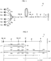
- Fig. 1 is a block diagram illustrating the configuration of the fiber laser device FL in accordance with Embodiment 1 of the present invention.
- the fiber laser device FL is a laser device for processing which laser device includes a single amplifying fiber.
- the fiber laser device FL includes m excitation light sources PS1 through PSm, m excitation fibers PF1 through PFm, an excitation combiner PC, a high-reflection fiber Bragg grating FBG-HR, an amplifying fiber AF, a low-reflection fiber Bragg grating FBG-LR, a delivery fiber DF, and an irradiation head H, for example, as illustrated in Fig. 1 .
- the excitation light sources PS1 through PSm correspond to the respective excitation fibers PF1 through PFm.
- m is any natural number of 2 or more and indicates the number of the excitation light sources PS1 through PSm and the number of the excitation fibers PF1 through PFm.
- An excitation light source PSj (j is a natural number of 1 or more and m or less) generates excitation light.
- a laser diode is employed as each of the excitation light sources PS1 through PSm.
- the excitation light source PSj is connected to an input end of an excitation fiber PFj.
- the excitation light which has been generated by the excitation light source PSj is inputted into the excitation fiber PFj.
- the excitation light which has been generated by the excitation light source PSj is guided in the excitation fiber PFj (j is a natural number of 1 or more and m or less).
- An output end of the excitation fiber PFj is connected to an input port of the excitation combiner PC.
- the excitation light which has been guided in the excitation fiber PFj is inputted into the excitation combiner PC via the input port.
- the excitation combiner PC combines the excitation light which has been guided in each of the excitation fibers PF1 through PFm.
- An output port of the excitation combiner PC is connected to an input end of the amplifying fiber AF via the high-reflection fiber Bragg grating FBG-HR.
- excitation light which has passed through the high-reflection fiber Bragg grating FBG-HR is inputted into the amplifying fiber AF.
- the amplifying fiber AF generates laser light with use of the excitation light which has passed through the high-reflection fiber Bragg grating FBG-HR.
- a double cladding fiber is employed which includes a core that is doped with a rare earth element (for example, Yb).
- the excitation light which has passed through the high-reflection fiber Bragg grating FBG-HR is used to keep the rare earth element in a population inversion state.
- An output end of the amplifying fiber AF is connected to an input end of the delivery fiber DF via the low-reflection fiber Bragg grating FBG-LR.
- the high-reflection fiber Bragg grating FBG-HR functions as a mirror in a certain wavelength band (for example, a reflectance is 99%), and the low-reflection fiber Bragg grating FBG-LR functions as a half mirror in the certain wavelength band (for example, a reflectance is 10%). Therefore, the amplifying fiber AF constitutes, together with the high-reflection fiber Bragg grating FBG-HR and the low-reflection fiber Bragg grating FBG-LR, a resonator which oscillates laser light that belongs to a specific wavelength band. Of the laser light which has been generated by the amplifying fiber AF, laser light which has passed through the low-reflection fiber Bragg grating FBG-LR is inputted into the delivery fiber DF.
- the laser light which has passed through the low-reflection fiber Bragg grating FBG-LR is guided in the delivery fiber DF.
- the delivery fiber DF a single-mode fiber or a few-mode fiber is employed.
- An output end of the delivery fiber DF is connected to the irradiation head H.
- the laser light which has been guided in the delivery fiber DF is emitted to a workpiece W via the irradiation head H.
- the fiber laser device FL in accordance with Embodiment 1 is characterized in that the fiber laser device FL includes a Raman filter RF for reflecting Stokes light generated by stimulated Raman scattering (hereinafter, referred to as "Raman scattered light").
- the Raman filter RF is provided to the delivery fiber DF.
- a fiber Bragg grating may be employed, a slanted fiber grating may be alternatively employed, or a long-period fiber Bragg grating may be alternatively employed.
- the Raman filter RF is designed so that a central wavelength of the Raman scattered light is included in a reflection bandwidth, and the Raman filter RF reflects part of the Raman scattered light which has entered the Raman filter RF and transmits part of the Raman scattered light which has entered the Raman filter RF.
- Fig. 2 is a drawing illustrating light paths of the Raman scattered light in the fiber laser device FL.
- the Raman scattered light which has entered the amplifying fiber AF from the high-reflection fiber Bragg grating FBG-HR returns to the high-reflection fiber Bragg grating FBG-HR from the amplifying fiber AF along a first light path ⁇ 1 or a second light path y2.
- the first light path ⁇ 1 is a light path along which the Raman scattered light propagates as follows.
- a "forward direction” indicates a direction identical to a direction in which the laser light is emitted from an end of the delivery fiber DF
- a “backward direction” indicates a direction opposite to the direction in which the laser light is emitted from the end of the delivery fiber DF (a direction in which reflected light that is reflected by the workpiece W is guided in the delivery fiber DF).
- the Raman scattered light which propagates along the first light path ⁇ 1 receives gain in the above-described process (1a), process (1c), process (1e), and process (1g).
- the gain which the Raman scattered light receives is 2 ⁇ g1 ⁇ L1 [dB].
- L1 represents a length of a light path from one of ends of the amplifying fiber AF which one is located on an opposite side to the delivery fiber DF (connection point between the amplifying fiber AF and the high-reflection fiber Bragg grating FBG-HR) to the Raman filter RF
- g1 [dB] represents gain which the Raman scattered light receives per unit length in the light path.
- the Raman scattered light which propagates along the first light path ⁇ 1 also receives loss in the above-described process (1d).
- the loss which the Raman scattered light receives is am [dB].
- am [dB] represents a reflection attenuation by the Raman filter RF. Therefore, power of the Raman scattered light becomes 10 (2 ⁇ g1 ⁇ L1-am)/10 times greater than original power in a process of propagating along the first light path ⁇ 1.
- the second light path y2 is a light path along which the Raman scattered light propagates as follows.
- the Raman scattered light which propagates along the second light path y2 receives gain in the above-described process (2a), process (2c), process (2e), process (2i), process (2k), and process (2m).
- the gain which the Raman scattered light receives is 2 ⁇ g1 ⁇ L1+2 ⁇ g2 ⁇ L2.
- L2 represents a length of a light path from the Raman filter RF to one of ends of the delivery fiber DF which one is located on an opposite side to the amplifying fiber AF (connection point between the delivery fiber DF and the irradiation head H)
- g2 [dB] represents gain which the Raman scattered light receives per unit length in the light path.
- the Raman scattered light which propagates along the second light path y2 also receives loss in the above-described process (2d), process (2g), and process (2j).
- the loss which the Raman scattered light receives is 2 ⁇ at+ar.
- at [dB] represents a transmission attenuation by the Raman filter RF
- ar [dB] represents a reflection attenuation by the workpiece W. Therefore, the power of the Raman scattered light becomes 10 (2 ⁇ g1 ⁇ L1+2 ⁇ g2 ⁇ L2-2 ⁇ at-ar)/10 times greater than the original power in a process of propagating along the second light path y2.
- the Raman scattered light which has entered the amplifying fiber AF from the high-reflection fiber Bragg grating FBG-HR has power that is 10 (2 ⁇ g1 ⁇ L1-am)/10 times greater than the original power.
- the Raman scattered light which has entered the amplifying fiber AF from the high-reflection fiber Bragg grating FBG-HR the Raman scattered light which propagates along the second light path y2 and then returns to the high-reflection fiber Bragg grating FBG-HR has power that is 10 (2 ⁇ g1 ⁇ L1+2 ⁇ g2 ⁇ L2-2 ⁇ at-ar)/10 times greater than the original power.
- the Raman scattered light which has entered the amplifying fiber AF from the high-reflection fiber Bragg grating FBG-HR has, in total, power that is 10 (2 ⁇ g2 ⁇ L1-am)/10 +10 (2 ⁇ g1 ⁇ L1+2 ⁇ g2 ⁇ L2-2 ⁇ at-ar)/10 times greater than the original power.
- the Raman scattered light which returns to the high-reflection fiber Bragg grating FBG-HR, of the Raman scattered light which has entered the amplifying fiber AF from the high-reflection fiber Bragg grating FBG-HR has, in total, power that is 10 (2 ⁇ g1 ⁇ L1+2 ⁇ g2 ⁇ L2-ar)/10 times greater than the original power.
- the Raman scattered light receives gain in (a) a process of propagating in the amplifying fiber AF in the forward direction from the high-reflection fiber Bragg grating FBG-HR to the low-reflection fiber Bragg grating FBG-LR, (b) a process of propagating in the delivery fiber DF in the forward direction from the low-reflection fiber Bragg grating FBG-LR to the irradiation head H, (c) a process of propagating in the delivery fiber DF in the backward direction from the irradiation head H to the low-reflection fiber Bragg grating FBG-LR, and (d) a process of propagating in the amplifying fiber AF in the backward direction from the low-reflection fiber Bragg grating FBG-LR to the high-reflection fiber Bragg grating FBG-HR, and the Raman scattered light receives loss in a process of being reflected by the workpiece W.
- the Raman filter RF is provided so that the Raman scattered light which returns to the high-reflection fiber Bragg grating FBG-HR, of the Raman scattered light which has entered the amplifying fiber AF from the high-reflection fiber Bragg grating FBG-HR, has, in total, power lower than that in a case where the Raman filter RF is not present. That is, according to the fiber laser device FL in accordance with Embodiment 1, the Raman filter RF is provided so that the following inequality (1) is satisfied.
- ar in a case where the workpiece W is predetermined, ar can be a reflection attenuation by the workpiece W, and in a case where the workpiece W is not predetermined, ar can be a reflection attenuation by a processable workpiece W. Note also that in a case where a range of the reflection attenuation by the processable workpiece W is predetermined, ar can be a minimum value, a maximum value, a median value, or the like of the range.
- L represents a length of a light path from the one of the ends of the amplifying fiber AF which one is located on the opposite side to the delivery fiber DF to the one of the ends of the delivery fiber DF which one is located on the opposite side to the amplifying fiber AF, and corresponds to a sum of the length L1 and the length L2.
- L will be also referred to as a "total light path length".
- the fiber laser device FL in accordance with Embodiment 1 can be regarded as a fiber laser device in which the Raman filter RF is provided so that the inequality (2) is satisfied or can be alternatively regarded as a fiber laser device in which the Raman filter RF is provided so that the inequality (3) is satisfied.
- a configuration such that the Raman filter RF is provided so that the inequality (2) is satisfied includes: a mode in which the position of the Raman filter RF is determined so that L2 satisfies the inequality (2); and a mode in which the Raman filter RF is designed or selected so that am and at satisfy the inequality (2).
- the Raman filter RF is provided so that any of the inequalities (1) through (3) is satisfied. Therefore, according to the fiber laser device FL in accordance with Embodiment 1, it is possible to suppress an increase in power of the Raman scattered light and thereby reduce a possibility that oscillation of the laser light becomes unstable.
- gain g1 which the Raman scattered light receives per unit length in the light path from the high-reflection fiber Bragg grating FBG-HR to the Raman filter RF
- gain g2 which the Raman scattered light receives in the light path from the Raman filter RF to the irradiation head H
- gain which the Raman scattered light receives per unit length can be given as a function g(P(z)) of a light path length z from an emitting end of the high-reflection fiber Bragg grating FBG-HR.
- P(z) is power of the laser light at a point at which the light path length from the emitting end of the high-reflection fiber Bragg grating FBG-HR is z
- g(P(z)) is the gain which the Raman scattered light receives per unit length at the point.
- the gain g1 ⁇ L1 and the gain g2 ⁇ L2 which appear in the above inequalities can be replaced with the following integral expressions (4) and (5), respectively.
- the inequalities (1) and (2) can be expressed by the following inequalities (6) and (7), respectively.
- the fiber laser device FL in accordance with Embodiment 1 can be regarded as a fiber laser device in which the Raman filter RF is provided so that the inequality (6) is satisfied or can be alternatively regarded as a fiber laser device in which the Raman filter RF is provided so that the inequality (7) is satisfied.
- the power P(z) is given by the following equality (9) with use of r' oc defined by the following equality (8).
- L0 is a length of the amplifying fiber AF
- r oc is a reflection attenuation by the low-reflection fiber Bragg grating FBG-LR
- toc is a transmission attenuation by the low-reflection fiber Bragg grating FBG-LR
- P is the power of the laser light outputted from the amplifying fiber via the fiber Bragg grating.
- r' oc is an apparent reflection attenuation by the fiber Bragg grating FBG-LR which apparent reflection attenuation results from an effect of reflection by a surface of the workpiece W.
- r oc ′ 10 ⁇ log 10 10 r oc 10 + 10 2 t oc + ar 10
- P z P ⁇ 10 r ′ oc 20 ⁇ L 0 ⁇ L 0 ⁇ z + 10 r ′ oc 20 ⁇ L 0 ⁇ L 0 + z
- the Raman filter RF is preferably provided so that the inequality (10) is further satisfied. 2 ⁇ L 1 L 1 + L 2 g P z dz ⁇ ar ⁇ am ⁇ 0
- the Raman filter RF is provided so that the inequality (10) is further satisfied, it is difficult for both of two resonators, which are formed on respective both sides of the Raman filter RF, to satisfy an oscillation condition. Therefore, according to the fiber laser device FL which is designed so that the inequality (10) is satisfied, it is possible to further suppress an increase in power of the Raman scattered light and thereby further reduce a possibility that the oscillation of the laser light becomes unstable.
- the two resonators can be, for example, (i) a resonator which is constituted by the light path from the high-reflection fiber Bragg grating FBG-HR to the Raman filter RF and (ii) a resonator which is constituted by a light path from the Raman filter RF to the workpiece W.
- the high-reflection fiber Bragg grating FBG-HR may function as a mirror which is paired with the Raman filter RF or alternatively a material of the amplifying fiber AF which material scatters the Raman scattered light may function as the mirror.
- the Raman filter RF is preferably constituted by a slanted fiber Bragg grating.
- a slanted fiber Bragg grating since part of light which propagates in a core can couple into a cladding mode, it is possible to cause a sum of an absolute value of a reflectance with respect to Raman scattered light and an absolute value of a transmittance with respect to the Raman scattered light to be lower than 1 (one).
- the Raman filter RF is constituted by a slanted fiber Bragg grating, it is possible to avoid a design constraint which can arise in a case where a sum of an absolute value of a reflectance with respect to the Raman scattered light and an absolute value of a transmittance with respect to the Raman scattered light is 1 (one).
- the Raman filter RF is preferably constituted by a long-period fiber Bragg grating.
- a long-period fiber Bragg grating since part of light which propagates in a core can couple into a cladding mode, it is possible to cause a sum of an absolute value of a reflectance with respect to Raman scattered light and an absolute value of a transmittance with respect to the Raman scattered light to be lower than 1 (one).
- the Raman filter RF is constituted by a long-period fiber Bragg grating, it is possible to avoid a design constraint which can arise in a case where the sum of the absolute value of the reflectance with respect to the Raman scattered light and the absolute value of the transmittance with respect to the Raman scattered light is 1 (one).
- a few-mode fiber may be employed as the amplifying fiber AF or the delivery fiber DF.
- a partially-doped fiber may be employed.
- an amplifying fiber may be employed which does not include a Raman reflecting part that reflects Raman scattered light.
- a fiber laser device FL As an Example of the fiber laser device FL, a fiber laser device FL was prepared which was configured such that a length L of a light path from a high-reflection fiber Bragg grating FBG-HR to an irradiation head H was 24 m. According to the fiber laser device FL, a length L1 of a light path from the high-reflection fiber Bragg grating FBG-HR to a Raman filter RF was 18 m, and gain g1 which Raman scattered light received per unit length in the light path was 1.2 dB/m.
- a length L2 of a light path from the Raman filter RF to the irradiation head H was 6 m, and gain g2 which the Raman scattered light received per unit length in the light path was 1.2 dB/m.
- the Raman filter RF a fiber Bragg grating was employed which was configured such that, in a reflection bandwidth including a central wavelength of the Raman scattered light, a reflection attenuation am was 0.5 dB and a transmission attenuation at was 10 dB.
- Fig. 3 shows results of determining, by numerical calculation, distribution of power of the Raman scattered light which propagated in a forward direction and a backward direction in the fiber laser device FL in accordance with the present Example.
- (a) of Fig. 3 is the distribution of the power of the Raman scattered light in a case where a reflectance of a workpiece W was 10% (a reflection attenuation ar was 10 dB).
- (b) of Fig. 3 is the distribution of the power of the Raman scattered light in a case where the reflectance of the workpiece W was 50% (the reflection attenuation ar was 3 dB).
- the fiber laser device in accordance with the Comparative Example indicates a fiber laser device obtained by removing the Raman filter RF from the fiber laser device FL in accordance with the present Example.
- Fig. 4 is a block diagram illustrating the configuration of the fiber laser device FLS in accordance with Embodiment 2.
- the fiber laser device FLS is a laser device for processing which laser device includes a plurality of amplifying fibers.
- the fiber laser device FLS includes n fiber laser units FLU1 through FLUn, n delivery fibers DF1 through DFn, an output combiner OC, a delivery fiber DF, and an irradiation head H, for example, as illustrated in Fig. 4 .
- the fiber laser units FLU1 through FLUn correspond to the respective delivery fibers DF1 through DFn.
- "n" is any natural number of 2 or more and indicates the number of the fiber laser units FLU1 through FLUn, the number of the delivery fibers DF1 through DFn, and the number of Raman filters RF1 through RFn (later described).
- a fiber laser unit FLUi (i is a natural number of 1 or more and n or less) generates laser light.
- the fiber laser unit FLUi includes m excitation light sources PS1 through PSm, m excitation fibers PF1 through PFm, an excitation combiner PC, a high-reflection fiber Bragg grating FBG-HR, an amplifying fiber AF, and a low-reflection fiber Bragg grating FBG-LR.
- the low-reflection fiber Bragg grating FBG-LR of the fiber laser unit FLUi is connected to an input end of a delivery fiber DFi.
- the laser light which has been generated by the fiber laser unit FLUi is inputted into the delivery fiber DFi.
- the laser light which has been generated in the fiber laser unit FLUi is guided in the delivery fiber DFi (i is a natural number of 1 or more and n or less).
- a single-mode fiber or a few-mode fiber is employed as each of the delivery fibers DF1 through DFn.
- An output end of the delivery fiber DFi is connected to an input port of the output combiner OC.
- the laser light which has been guided in the delivery fiber DFi is inputted into the output combiner OC via the input port.
- the output combiner OC combines the laser light which has been guided in each of the delivery fibers DF1 through DFn.
- An output port of the output combiner OC is connected to an input end of the delivery fiber DF.
- the laser light which has been combined by the output combiner OC is inputted into the delivery fiber DF.
- the laser light which has been combined by the output combiner OC is guided in the delivery fiber DF.
- the delivery fiber DF a multimode fiber is employed as the delivery fiber DF.
- An output end of the delivery fiber DF is connected to the irradiation head H.
- the laser light which has been guided in the delivery fiber DF is emitted to a workpiece W via the irradiation head H.
- the fiber laser device FLS is characterized in that the fiber laser device FLS includes the Raman filters RF1 through RFn each for reflecting Stokes light generated by stimulated Raman scattering (hereinafter, referred to as "Raman scattered light").
- a Raman filter RFi i is a natural number of 1 or more and n or less
- a fiber Bragg grating may be employed, a slanted fiber grating may be alternatively employed, or a long-period fiber Bragg grating may be alternatively employed.
- Each of the Raman filters RF1 through RFn is designed so that a central wavelength of the Raman scattered light is included in a reflection bandwidth, and each of the Raman filters RF1 through RFn reflects part of the Raman scattered light which has entered the each of the Raman filters RF1 through RFn and transmits part of the Raman scattered light which has entered the each of the Raman filters RF1 through RFn.
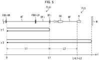
- Fig. 5 is a drawing illustrating light paths of the Raman scattered light in the fiber laser device FLUi. As illustrated in Fig. 5 , the Raman scattered light which has entered the amplifying fiber AF from the high-reflection fiber Bragg grating FBG-HR returns to the high-reflection fiber Bragg grating FBG-HR along a first light path ⁇ 1 or a second light path y2.
- the Raman filter RFi is provided so that the Raman scattered light which returns to the high-reflection fiber Bragg grating FBG-HR has, in total, power lower than that in a case where the Raman filter RFi is not present. That is, according to the fiber laser device FLS in accordance with Embodiment 2, the Raman filter RFi is provided so that the following inequality (1) is satisfied. 10 2 ⁇ g 1 ⁇ L 1 ⁇ am 10 + 10 2 ⁇ g 1 ⁇ L 1 + 2 ⁇ g 2 ⁇ L 2 ⁇ 2 ⁇ at ⁇ ar 10 ⁇ 10 2 ⁇ g 1 ⁇ L 1 + 2 ⁇ g 2 ⁇ L 2 ⁇ ar 10
- L1 represents a length of a light path from one of ends of the amplifying fiber AF which one is located on an opposite side to the delivery fiber DF (connection point between the amplifying fiber AF and the high-reflection fiber Bragg grating FBG-HR) to the Raman filter RFi
- g1 [dB] represents gain which the Raman scattered light receives per unit length in the light path.
- L2 represents a length of a light path from the Raman filter RFi to one of ends of the delivery fiber DF which one is located on an opposite side to the amplifying fiber AF (connection point between the delivery fiber DF and the irradiation head H), and g2 [dB] represents gain which the Raman scattered light receives per unit length in the light path.
- am [dB] represents a reflection attenuation by the Raman filter RFi
- at [dB] represents a transmission attenuation by the Raman filter RFi.
- ar [dB] represents a reflection attenuation by the workpiece W.
- L represents a length of a light path from the one of the ends of the amplifying fiber AF which one is located on the opposite side to the delivery fiber DF to the one of the ends of the delivery fiber DF which one is located on the opposite side to the amplifying fiber AF, and corresponds to a sum of the length L1 and the length L2.
- the fiber laser device FLS in accordance with Embodiment 2 can be regarded as a fiber laser device in which the Raman filter RFi is provided so that the inequality (12) is satisfied or can be alternatively regarded as a fiber laser device in which the Raman filter RFi is provided so that the inequality (13) is satisfied.
- the Raman filter RFi is provided so that any of the inequalities (1) through (3) is satisfied. Therefore, according to the fiber laser device FLS in accordance with Embodiment 2, it is possible to suppress an increase in power of the Raman scattered light and thereby reduce a possibility that oscillation of the laser light becomes unstable.
- gain g1 which the Raman scattered light receives per unit length in the light path from the high-reflection fiber Bragg grating FBG-HR to the Raman filter RFi
- gain g2 which the Raman scattered light receives in the light path from the Raman filter RFi to the irradiation head H
- gain which the Raman scattered light receives per unit length can be given as a function g(P(z)) of a light path length z from an emitting end of the high-reflection fiber Bragg grating FBG-HR.
- P(z) is power of the laser light at a point at which the light path length from the emitting end of the high-reflection fiber Bragg grating FBG-HR is z.
- the gain g1 ⁇ L1 and the gain g2 ⁇ L2 which appear in the above inequalities can be generalized to the following expressions (14) and (15), respectively.
- the inequalities (11) and (12) can be generalized to the following inequalities (16) and (17), respectively.
- the fiber laser device FL in accordance with Embodiment 2 can be regarded as a fiber laser device in which the Raman filter RFi is provided so that the inequality (16) is satisfied or can be alternatively regarded as a fiber laser device in which the Raman filter RFi is provided so that the inequality (17) is satisfied.
- the power P(z) is given by the following equality (19) with use of r' oc defined by the following equality (18).
- L0 is a length of the amplifying fiber AF
- r oc is a reflection attenuation by the low-reflection fiber Bragg grating FBG-LR
- toc is a transmission attenuation by the low-reflection fiber Bragg grating FBG-LR.
- the Raman filter RFi is preferably provided so that the inequality (20) is further satisfied. 2 ⁇ L 1 L 1 + L 2 g P z dz ⁇ ar ⁇ am ⁇ 0
- the Raman filter RFi is provided so that the inequality (20) is satisfied, it is difficult for both of two resonators, which are formed on respective both sides of the Raman filter RFi, to satisfy an oscillation condition. Therefore, according to the fiber laser device FLS in which the Raman filter RFi is provided so that the inequality (20) is satisfied, it is possible to further suppress an increase in power of the Raman scattered light and thereby further reduce a possibility that the oscillation of the laser light becomes unstable.
- the Raman filter RFi is preferably constituted by a slanted fiber Bragg grating.
- a design constraint which can arise in a case where a sum of an absolute value of a reflectance with respect to the Raman scattered light and an absolute value of a transmittance with respect to the Raman scattered light is 1 (one).
- the Raman filter RFi is preferably constituted by a long-period fiber Bragg grating. In this case, it is possible to avoid a design constraint which can arise in a case where the sum of the absolute value of the reflectance with respect to the Raman scattered light and the absolute value of the transmittance with respect to the Raman scattered light is 1 (one).
- a few-mode fiber may be employed as the amplifying fiber AF, the delivery fiber DFi, or the delivery fiber DF.
- the amplifying fiber AF the delivery fiber DFi, or the delivery fiber DF
- a partially-doped fiber may be employed.
- an amplifying fiber may be employed which does not include a Raman reflecting part that reflects Raman scattered light.
- the fiber laser device FL in accordance with Embodiment 1 can be produced by a production method including a step of providing the Raman filter RF so that the inequality (1), (2), (3), (6), or (7) is satisfied.
- a production method including a step of providing the Raman filter RF so that the inequality (1), (2), (3), (6), or (7) is satisfied.
- the step of providing the Raman filter RF can be carried out so that the inequality (10) is further satisfied. In this case, it is possible to produce the fiber laser device FL in which an increase in power of the Raman scattered light is further suppressed and thereby a possibility that the oscillation of the laser light becomes unstable is further reduced.
- the fiber laser device FLS in accordance with Embodiment 2 can be produced by a production method including a step of providing the Raman filter RFi so that the inequality (11), (12), (13), (16), or (17) is satisfied.
- a production method including a step of providing the Raman filter RFi so that the inequality (11), (12), (13), (16), or (17) is satisfied.
- the step of providing the Raman filter RFi can be carried out so that the inequality (20) is further satisfied. In this case, it is possible to produce the fiber laser device FLS in which an increase in power of the Raman scattered light is further suppressed and thereby a possibility that the oscillation of the laser light becomes unstable is further reduced.
- the inequality (1), (2), (3), (6), or (7) can be applied to a setting method of setting, in the fiber laser device FL in accordance with Embodiment 1, the reflection attenuation ar by the processable workpiece. That is, by setting the reflection attenuation ar so that the inequality (1), (2), (3), (6), or (7) is satisfied, it is possible to realize the fiber laser FL in which an increase in power of the Raman scattered light is suppressed and thereby a possibility that the oscillation of the laser light becomes unstable is reduced.
- a step of setting the reflection attenuation ar can be carried out so that the inequality (10) is further satisfied. In this case, it is possible to realize the fiber laser device FL in which an increase in power of the Raman scattered light is further suppressed and thereby a possibility that the oscillation of the laser light becomes unstable is further reduced.
- the inequality (11), (12), (13), (16), or (17) can be applied to a setting method of setting, in the fiber laser device FLS in accordance with Embodiment 2, a reflection attenuation ar by a processable workpiece. That is, by setting the reflection attenuation ar so that the inequality (11), (12), (13), (16), or (17) is satisfied, it is possible to realize the fiber laser FLS in which an increase in power of the Raman scattered light is suppressed and thereby a possibility that the oscillation of the laser light becomes unstable is reduced.
- a step of setting the reflection attenuation ar can be carried out so that the inequality (20) is further satisfied. In this case, it is possible to realize the fiber laser device FLS in which an increase in power of the Raman scattered light is further suppressed and thereby a possibility that the oscillation of the laser light becomes unstable is further reduced.
- the fiber laser devices FL and FLS each of which is of a resonator type, have been described.
- the present invention is not limited to such a type.
- the present invention can be applied to a fiber laser device of an MOPA (Master Oscillator - Power Amplifier) type.
- MOPA Master Oscillator - Power Amplifier
- this MOPA fiber laser device is a fiber laser device which includes: a laser light source which functions as an MO part; a fiber amplifier which functions as a PA part, and a delivery fiber.
- the MOPA fiber laser device laser light which has been outputted from an amplifying fiber that constitutes the PA part (fiber amplifier) is guided in the delivery fiber and then emitted to a workpiece.
- a delivery fiber is connected to a downstream end of an amplifying fiber via a fiber Bragg grating (the low-reflection fiber Bragg grating FBG-LR in Embodiments 1 and 2), whereas, according to a fiber laser device of an MOPA type, a delivery fiber is connected to a downstream end of an amplifying fiber without a fiber Bragg grating.
- a fiber laser device (FL, FLS) in accordance with an aspect of the present invention is a fiber laser device (FL, FLS) including: an amplifying fiber (AF); a delivery fiber (DF) in which laser light that has been outputted from the amplifying fiber (AF) is guided; and a Raman filter (RF, RF1 through RFn) which reflects part of Raman scattered light that is generated by stimulated Raman scattering caused to the laser light, the Raman filter (RF, RF1 through RFn) being provided so that the following inequality (a) is satisfied: 10 2 ⁇ g 1 ⁇ L 1 ⁇ am 10 + 10 2 ⁇ g 1 ⁇ L 1 + 2 ⁇ g 2 ⁇ L 2 ⁇ 2 ⁇ at ⁇ ar 10 ⁇ 10 2 ⁇ g 1 ⁇ L 1 + 2 ⁇ g 2 ⁇ L 2 ⁇ ar 10 where: L1 represents a length of a light path from one of ends of the amplifying fiber (AF) which one is located on an opposite side to the delivery fiber
- the fiber laser device (FL, FLS) in accordance with an aspect of the present invention is arranged such that the Raman filter (RF, RF1 through RFn) is provided so that, instead of the inequality (a), the following inequality (b) is satisfied: 10 ⁇ am 10 + 10 2 ⁇ g 2 ⁇ L 2 ⁇ 2 ⁇ at ⁇ ar 10 ⁇ 10 2 ⁇ g 2 ⁇ L 2 ⁇ ar 10
- the fiber laser device (FL, FLS) in accordance with an aspect of the present invention is arranged such that the Raman filter (RF, RF1 through RFn) is provided so that, instead of the inequality (a), the following inequality (c) is satisfied: 10 ⁇ am 10 + 10 2 ⁇ g 2 ⁇ L ⁇ L 1 ⁇ 2 ⁇ at ⁇ ar 10 ⁇ 10 2 ⁇ g 2 ⁇ L ⁇ L 1 ⁇ ar 10 where L represents a length of a light path from the one of the ends of the amplifying fiber (AF) which one is located on the opposite side to the delivery fiber (DF) to the one of the ends of the delivery fiber (DF) which one is located on the opposite side to the amplifying fiber (AF).
- the fiber laser device (FL, FLS) in accordance with an aspect of the present invention is preferably arranged such that the Raman filter (RF, RF1 through RFn) is provided so that the following inequality (d) is further satisfied: 2 ⁇ L 1 L 1 + L 2 g P z dz ⁇ ar ⁇ am ⁇ 0 where: P(z) represents power of the laser light at a point at which a light path length from the one of the ends of the amplifying fiber (AF) which one is located on the opposite side to the delivery fiber (DF) is z; and g(P(z)) represents gain which the Raman scattered light receives per unit length at the point.
- LO represents a length of the amplifying fiber (AF); r oc represents a reflection attenuation by the fiber Bragg grating (FBG-LR); toc is a transmission attenuation by the fiber Bragg grating
- the fiber laser device (FLS) in accordance with an aspect of the present invention is preferably arranged so as to further include: a plurality of amplifying fibers (AF) which include the amplifying fiber (AF); and a combiner which combines the laser light that has been outputted from each of the plurality of amplifying fibers (AF), the delivery fiber (DF) including: delivery fibers in each of which the laser light that has been outputted from a corresponding one of the plurality of amplifying fibers (AF) is guided to the combiner; and a delivery fiber in which the laser light that has been combined by the combiner is guided.
- AF amplifying fibers
- DF delivery fiber
- a production method in accordance with an aspect of the present invention is a method of producing a fiber laser device (FL, FLS) which includes: an amplifying fiber (AF); a delivery fiber (DF) in which laser light that has been outputted from the amplifying fiber (AF) is guided; and a Raman filter (RF, RF1 through RFn) which reflects part of Raman scattered light that is generated by stimulated Raman scattering caused to the laser light, the method including the step of providing the Raman filter (RF, RF1 through RFn) so that the following inequality (a) is satisfied: 10 2 ⁇ g 1 ⁇ L 1 ⁇ am 10 + 10 2 ⁇ g 1 ⁇ L 1 + 2 ⁇ g 2 ⁇ L 2 ⁇ 2 ⁇ at ⁇ ar 10 ⁇ 10 2 ⁇ g 1 ⁇ L 1 + 2 ⁇ g 2 ⁇ L 2 ⁇ ar 10 where: L1 represents a length of a light path from one of ends of the amplifying fiber (AF) which one is located on an opposite side
- a setting method in accordance with an aspect of the present invention is a method of setting, in a fiber laser device (FL, FLS), a reflection attenuation ar by a workpiece which is processable by the fiber laser device (FL, FLS), the fiber laser device (FL, FLS) including: an amplifying fiber (AF); and a delivery fiber (DF) in which laser light that has been outputted from the amplifying fiber (AF) is guided, the method including the step of setting the reflection attenuation ar so that the following inequality (a) is satisfied: 10 2 ⁇ g 1 ⁇ L 1 ⁇ am 10 + 10 2 ⁇ g 1 ⁇ L 1 + 2 ⁇ g 2 ⁇ L 2 ⁇ 2 ⁇ at ⁇ ar 10 ⁇ 10 2 ⁇ g 1 ⁇ L 1 + 2 ⁇ g 2 ⁇ L 2 ⁇ ar 10 where: L1 represents a length of a light path from one of ends of the amplifying fiber (AF) which one is located on an opposite side to the delivery fiber (DF) to a
- the present invention is not limited to the embodiments, but can be altered by a skilled person in the art within the scope of the claims.
- the present invention also encompasses, in its technical scope, any embodiment derived by combining technical means disclosed in differing embodiments.
Landscapes
- Physics & Mathematics (AREA)
- Electromagnetism (AREA)
- Engineering & Computer Science (AREA)
- Plasma & Fusion (AREA)
- Optics & Photonics (AREA)
- Lasers (AREA)
- Optical Modulation, Optical Deflection, Nonlinear Optics, Optical Demodulation, Optical Logic Elements (AREA)
- Optical Fibers, Optical Fiber Cores, And Optical Fiber Bundles (AREA)
- Laser Beam Processing (AREA)
- Light Guides In General And Applications Therefor (AREA)
Abstract
Description
- The present invention relates to a fiber laser device. The present invention further relates to a production method of producing a fiber laser device. The present invention also relates to a setting method of, in a fiber laser device, setting a reflection attenuation by a processable workpiece.
- In the field of material processing, fiber laser devices have drawn attention as laser beam machines which are excellent in ease of maintenance and processing ability. However, in a fiber laser device, in a case where a power density of laser light guided in an optical fiber becomes high, a nonlinear optical effect, such as stimulated Raman scattering, becomes likely to be brought about. Further, it is known that, in a case where power of Raman scattered light generated by stimulated Raman scattering becomes high, laser oscillation in a fiber laser device becomes unstable (see Patent Literature 1).
- [Patent Literature 1] Japanese Patent Application Publication Tokukai No.
2015-95641 - However, conventional fiber laser devices still have room for a further reduction in possibility that oscillation of laser light becomes unstable, by further suppression of an increase in power of Raman scattered light.
- The present invention has been made in view of the above point, and an object of the present invention is to (1) in a fiber laser device, suppress an increase in power of Raman scattered light and thereby reduce a possibility that oscillation of laser light becomes unstable, (2) produce a fiber laser device in which an increase in power of Raman scattered light is suppressed and thereby a possibility that oscillation of laser light becomes unstable is reduced, or (3) realize a fiber laser device in which an increase in power of Raman scattered light is suppressed and thereby a possibility that oscillation of laser light becomes unstable is reduced.
- In order to attain the above object, a fiber laser device in accordance with an aspect of the present invention is a fiber laser device including: an amplifying fiber; a delivery fiber in which laser light that has been outputted from the amplifying fiber is guided; and a Raman filter which reflects part of Raman scattered light that is generated by stimulated Raman scattering caused to the laser light, the Raman filter being provided so that the following inequality (a) is satisfied:

where: L1 represents a length of a light path from one of ends of the amplifying fiber which one is located on an opposite side to the delivery fiber to the Raman filter; g1 represents gain which the Raman scattered light receives per unit length in the light path; L2 represents a length of a light path from the Raman filter to one of ends of the delivery fiber which one is located on an opposite side to the amplifying fiber; g2 represents gain which the Raman scattered light receives per unit length in the light path; am represents a reflection attenuation by the Raman filter; at represents a transmission attenuation by the Raman filter; and ar represents a reflection attenuation by a workpiece which is processable by the fiber laser device. - In order to attain the above object, a production method in accordance with an aspect of the present invention is a method of producing a fiber laser device which includes: an amplifying fiber; a delivery fiber in which laser light that has been outputted from the amplifying fiber is guided; and a Raman filter which reflects part of Raman scattered light that is generated by stimulated Raman scattering caused to the laser light, the method including the step of providing the Raman filter so that the following inequality (a) is satisfied:

where: L1 represents a length of a light path from one of ends of the amplifying fiber which one is located on an opposite side to the delivery fiber to the Raman filter; g1 represents gain which the Raman scattered light receives per unit length in the light path; L2 represents a length of a light path from the Raman filter to one of ends of the delivery fiber which one is located on an opposite side to the amplifying fiber; g2 represents gain which the Raman scattered light receives per unit length in the light path; am represents a reflection attenuation by the Raman filter; at represents a transmission attenuation by the Raman filter; and ar represents a reflection attenuation by a workpiece which is processable by the fiber laser device. - In order to attain the above object, a setting method in accordance with an aspect of the present invention is a method of setting, in a fiber laser device, a reflection attenuation ar by a workpiece which is processable by the fiber laser device, the fiber laser device including: an amplifying fiber; and a delivery fiber in which laser light that has been outputted from the amplifying fiber is guided, the method including the step of setting the reflection attenuation ar so that the following inequality (a) is satisfied:

where: L1 represents a length of a light path from one of ends of the amplifying fiber which one is located on an opposite side to the delivery fiber to a Raman filter; g1 represents gain which Raman scattered light receives per unit length in the light path; L2 represents a length of a light path from the Raman filter to one of ends of the delivery fiber which one is located on an opposite side to the amplifying fiber; g2 represents gain which the Raman scattered light receives per unit length in the light path; am represents a reflection attenuation by the Raman filter; at represents a transmission attenuation by the Raman filter; and ar represents the reflection attenuation by the workpiece which is processable by the fiber laser device. - According to a fiber laser device in accordance with an aspect of the present invention, it is possible to suppress an increase in power of Raman scattered light and thereby reduce a possibility that oscillation of laser light becomes unstable. Furthermore, according to a method of producing a fiber laser device in accordance with an aspect of the present invention, it is possible to produce a fiber laser device in which an increase in power of Raman scattered light is suppressed and thereby a possibility that oscillation of laser light becomes unstable is reduced. Moreover, according to a setting method in accordance with an aspect of the present invention, it is possible to realize a fiber laser device in which an increase in power of Raman scattered light is suppressed and thereby a possibility that oscillation of laser light becomes unstable is reduced.
-
-
Fig. 1 is a block diagram illustrating a configuration of a fiber laser device in accordance with Embodiment 1 of the present invention. -
Fig. 2 is a drawing illustrating light paths of Raman scattered light in the fiber laser device illustrated inFig. 1 . -
Fig. 3 is a drawing illustrating distribution of power of the Raman scattered light in the fiber laser device illustrated inFig. 1 . (a) ofFig. 3 illustrates the distribution of the power of the Raman scattered light in a case where a reflectance of a workpiece is 10%. (b) ofFig. 3 illustrates distribution of the power of the Raman scattered light in a case where the reflectance of the workpiece is 50%. -
Fig. 4 is a block diagram illustrating a configuration of a fiber laser device in accordance with Embodiment 2 of the present invention. -
Fig. 5 is a drawing illustrating light paths of Raman scattered light in the fiber laser device illustrated inFig. 4 . - The following description will discuss a configuration of a fiber laser device FL in accordance with Embodiment 1 of the present invention with reference to
Fig. 1. Fig. 1 is a block diagram illustrating the configuration of the fiber laser device FL in accordance with Embodiment 1 of the present invention. - The fiber laser device FL is a laser device for processing which laser device includes a single amplifying fiber. The fiber laser device FL includes m excitation light sources PS1 through PSm, m excitation fibers PF1 through PFm, an excitation combiner PC, a high-reflection fiber Bragg grating FBG-HR, an amplifying fiber AF, a low-reflection fiber Bragg grating FBG-LR, a delivery fiber DF, and an irradiation head H, for example, as illustrated in
Fig. 1 . The excitation light sources PS1 through PSm correspond to the respective excitation fibers PF1 through PFm. Note, here, that "m" is any natural number of 2 or more and indicates the number of the excitation light sources PS1 through PSm and the number of the excitation fibers PF1 through PFm. Note thatFig. 1 illustrates an example of the configuration of the fiber laser device FL in a case where m = 6. - An excitation light source PSj (j is a natural number of 1 or more and m or less) generates excitation light. In Embodiment 1, as each of the excitation light sources PS1 through PSm, a laser diode is employed. The excitation light source PSj is connected to an input end of an excitation fiber PFj. The excitation light which has been generated by the excitation light source PSj is inputted into the excitation fiber PFj.
- The excitation light which has been generated by the excitation light source PSj is guided in the excitation fiber PFj (j is a natural number of 1 or more and m or less). An output end of the excitation fiber PFj is connected to an input port of the excitation combiner PC. The excitation light which has been guided in the excitation fiber PFj is inputted into the excitation combiner PC via the input port.
- The excitation combiner PC combines the excitation light which has been guided in each of the excitation fibers PF1 through PFm. An output port of the excitation combiner PC is connected to an input end of the amplifying fiber AF via the high-reflection fiber Bragg grating FBG-HR. Of the excitation light which has been combined by the excitation combiner PC, excitation light which has passed through the high-reflection fiber Bragg grating FBG-HR is inputted into the amplifying fiber AF.
- The amplifying fiber AF generates laser light with use of the excitation light which has passed through the high-reflection fiber Bragg grating FBG-HR. In Embodiment 1, as the amplifying fiber AF, a double cladding fiber is employed which includes a core that is doped with a rare earth element (for example, Yb). The excitation light which has passed through the high-reflection fiber Bragg grating FBG-HR is used to keep the rare earth element in a population inversion state. An output end of the amplifying fiber AF is connected to an input end of the delivery fiber DF via the low-reflection fiber Bragg grating FBG-LR. The high-reflection fiber Bragg grating FBG-HR functions as a mirror in a certain wavelength band (for example, a reflectance is 99%), and the low-reflection fiber Bragg grating FBG-LR functions as a half mirror in the certain wavelength band (for example, a reflectance is 10%). Therefore, the amplifying fiber AF constitutes, together with the high-reflection fiber Bragg grating FBG-HR and the low-reflection fiber Bragg grating FBG-LR, a resonator which oscillates laser light that belongs to a specific wavelength band. Of the laser light which has been generated by the amplifying fiber AF, laser light which has passed through the low-reflection fiber Bragg grating FBG-LR is inputted into the delivery fiber DF.
- The laser light which has passed through the low-reflection fiber Bragg grating FBG-LR is guided in the delivery fiber DF. In Embodiment 1, as the delivery fiber DF, a single-mode fiber or a few-mode fiber is employed. An output end of the delivery fiber DF is connected to the irradiation head H. The laser light which has been guided in the delivery fiber DF is emitted to a workpiece W via the irradiation head H.
- The fiber laser device FL in accordance with Embodiment 1 is characterized in that the fiber laser device FL includes a Raman filter RF for reflecting Stokes light generated by stimulated Raman scattering (hereinafter, referred to as "Raman scattered light"). In Embodiment 1, the Raman filter RF is provided to the delivery fiber DF. As the Raman filter RF, a fiber Bragg grating may be employed, a slanted fiber grating may be alternatively employed, or a long-period fiber Bragg grating may be alternatively employed. The Raman filter RF is designed so that a central wavelength of the Raman scattered light is included in a reflection bandwidth, and the Raman filter RF reflects part of the Raman scattered light which has entered the Raman filter RF and transmits part of the Raman scattered light which has entered the Raman filter RF.
-
Fig. 2 is a drawing illustrating light paths of the Raman scattered light in the fiber laser device FL. As illustrated inFig. 2 , the Raman scattered light which has entered the amplifying fiber AF from the high-reflection fiber Bragg grating FBG-HR returns to the high-reflection fiber Bragg grating FBG-HR from the amplifying fiber AF along a first light path γ1 or a second light path y2. - Note, here, that the first light path γ1 is a light path along which the Raman scattered light propagates as follows. Note that, in the following description, a "forward direction" indicates a direction identical to a direction in which the laser light is emitted from an end of the delivery fiber DF, and a "backward direction" indicates a direction opposite to the direction in which the laser light is emitted from the end of the delivery fiber DF (a direction in which reflected light that is reflected by the workpiece W is guided in the delivery fiber DF).
- (1a) The Raman scattered light propagates in the amplifying fiber AF in the forward direction from the high-reflection fiber Bragg grating FBG-HR to the low-reflection fiber Bragg grating FBG-LR,
- (1b) passes through the low-reflection fiber Bragg grating FBG-LR,
- (1c) propagates in the delivery fiber DF in the forward direction from the low-reflection fiber Bragg grating FBG-LR to the Raman filter RF,
- (1d) is reflected by the Raman filter RF,
- (1e) propagates in the delivery fiber DF in the backward direction from the Raman filter RF to the low-reflection fiber Bragg grating FBG-LR,
- (If) passes through the low-reflection fiber Bragg grating FBG-LR, and
- (1g) propagates in the amplifying fiber AF in the backward direction from the low-reflection fiber Bragg grating FBG-LR to the high-reflection fiber Bragg grating FBG-HR.
- The Raman scattered light which propagates along the first light path γ1 receives gain in the above-described process (1a), process (1c), process (1e), and process (1g). In these processes, the gain which the Raman scattered light receives is 2×g1×L1 [dB]. Here, L1 represents a length of a light path from one of ends of the amplifying fiber AF which one is located on an opposite side to the delivery fiber DF (connection point between the amplifying fiber AF and the high-reflection fiber Bragg grating FBG-HR) to the Raman filter RF, and g1 [dB] represents gain which the Raman scattered light receives per unit length in the light path. The Raman scattered light which propagates along the first light path γ1 also receives loss in the above-described process (1d). In this process, the loss which the Raman scattered light receives is am [dB]. Here, am [dB] represents a reflection attenuation by the Raman filter RF. Therefore, power of the Raman scattered light becomes 10(2×g1×L1-am)/10 times greater than original power in a process of propagating along the first light path γ1.
- On the other hand, the second light path y2 is a light path along which the Raman scattered light propagates as follows.
- (2a) The Raman scattered light propagates in the amplifying fiber AF in the forward direction from the high-reflection fiber Bragg grating FBG-HR to the low-reflection fiber Bragg grating FBG-LR,
- (2b) passes through the low-reflection fiber Bragg grating FBG-LR,
- (2c) propagates in the delivery fiber DF in the forward direction from the low-reflection fiber Bragg grating FBG-LR to the Raman filter RF,
- (2d) passes through the Raman filter RF,
- (2e) propagates in the delivery fiber DF in the forward direction from the Raman filter RF to the irradiation head H,
- (2f) propagates in air in the forward direction from the irradiation head H to the workpiece W,
- (2g) is reflected by the workpiece W,
- (2h) propagates in the air in the backward direction from the workpiece W to the irradiation head H,
- (2i) propagates in the delivery fiber DF in the backward direction from the irradiation head H to the Raman filter RF,
- (2j) passes through the Raman filter RF,
- (2k) propagates in the delivery fiber DF in the backward direction from the Raman filter RF to the low-reflection fiber Bragg grating FBG-LR,
- (21) passes through the low-reflection fiber Bragg grating FBG-LR, and
- (2m) propagates in the amplifying fiber AF in the backward direction from the low-reflection fiber Bragg grating FBG-LR to the high-reflection fiber Bragg grating FBG-HR.
- The Raman scattered light which propagates along the second light path y2 receives gain in the above-described process (2a), process (2c), process (2e), process (2i), process (2k), and process (2m). In these processes, the gain which the Raman scattered light receives is 2×g1×L1+2×g2×L2. Here, L2 represents a length of a light path from the Raman filter RF to one of ends of the delivery fiber DF which one is located on an opposite side to the amplifying fiber AF (connection point between the delivery fiber DF and the irradiation head H), and g2 [dB] represents gain which the Raman scattered light receives per unit length in the light path. The Raman scattered light which propagates along the second light path y2 also receives loss in the above-described process (2d), process (2g), and process (2j). In these process, the loss which the Raman scattered light receives is 2×at+ar. Here, at [dB] represents a transmission attenuation by the Raman filter RF, and ar [dB] represents a reflection attenuation by the workpiece W. Therefore, the power of the Raman scattered light becomes 10(2×g1×L1+2×g2×L2-2×at-ar)/10 times greater than the original power in a process of propagating along the second light path y2.
- As has been described, of the Raman scattered light which has entered the amplifying fiber AF from the high-reflection fiber Bragg grating FBG-HR, the Raman scattered light which propagates along the first light path γ1 and then returns to the high-reflection fiber Bragg grating FBG-HR has power that is 10(2×g1×L1-am)/10 times greater than the original power. Of the Raman scattered light which has entered the amplifying fiber AF from the high-reflection fiber Bragg grating FBG-HR, the Raman scattered light which propagates along the second light path y2 and then returns to the high-reflection fiber Bragg grating FBG-HR has power that is 10(2×g1×L1+2×g2×L2-2×at-ar)/10 times greater than the original power. Therefore, of the Raman scattered light which has entered the amplifying fiber AF from the high-reflection fiber Bragg grating FBG-HR, the Raman scattered light which returns to the high-reflection fiber Bragg grating FBG-HR has, in total, power that is 10(2×g2×L1-am)/10+10(2×g1×L1+2×g2×L2-2×at-ar)/10 times greater than the original power.
- By the way, in a case where the Raman filter RF is not present, the Raman scattered light which returns to the high-reflection fiber Bragg grating FBG-HR, of the Raman scattered light which has entered the amplifying fiber AF from the high-reflection fiber Bragg grating FBG-HR, has, in total, power that is 10(2×g1×L1+2×g2×L2-ar)/10 times greater than the original power. This is because, in this case, the Raman scattered light receives gain in (a) a process of propagating in the amplifying fiber AF in the forward direction from the high-reflection fiber Bragg grating FBG-HR to the low-reflection fiber Bragg grating FBG-LR, (b) a process of propagating in the delivery fiber DF in the forward direction from the low-reflection fiber Bragg grating FBG-LR to the irradiation head H, (c) a process of propagating in the delivery fiber DF in the backward direction from the irradiation head H to the low-reflection fiber Bragg grating FBG-LR, and (d) a process of propagating in the amplifying fiber AF in the backward direction from the low-reflection fiber Bragg grating FBG-LR to the high-reflection fiber Bragg grating FBG-HR, and the Raman scattered light receives loss in a process of being reflected by the workpiece W.
- According to the fiber laser device FL in accordance with Embodiment 1, the Raman filter RF is provided so that the Raman scattered light which returns to the high-reflection fiber Bragg grating FBG-HR, of the Raman scattered light which has entered the amplifying fiber AF from the high-reflection fiber Bragg grating FBG-HR, has, in total, power lower than that in a case where the Raman filter RF is not present. That is, according to the fiber laser device FL in accordance with Embodiment 1, the Raman filter RF is provided so that the following inequality (1) is satisfied. Note, however, that in a case where the workpiece W is predetermined, ar can be a reflection attenuation by the workpiece W, and in a case where the workpiece W is not predetermined, ar can be a reflection attenuation by a processable workpiece W. Note also that in a case where a range of the reflection attenuation by the processable workpiece W is predetermined, ar can be a minimum value, a maximum value, a median value, or the like of the range.

- Note that it is possible to transform the inequality (1) into the following inequality (2) by dividing both sides of the inequality (1) by 10(2×g1×L1)/10.

- Note also that it is possible to transform the inequality (2) into the following inequality (3) by substituting L2=L-L1 into the inequality (2). Here, L represents a length of a light path from the one of the ends of the amplifying fiber AF which one is located on the opposite side to the delivery fiber DF to the one of the ends of the delivery fiber DF which one is located on the opposite side to the amplifying fiber AF, and corresponds to a sum of the length L1 and the length L2. Hereinafter, L will be also referred to as a "total light path length".

- Therefore, the fiber laser device FL in accordance with Embodiment 1 can be regarded as a fiber laser device in which the Raman filter RF is provided so that the inequality (2) is satisfied or can be alternatively regarded as a fiber laser device in which the Raman filter RF is provided so that the inequality (3) is satisfied.
- Note that a configuration such that the Raman filter RF is provided so that the inequality (1) is satisfied includes: a mode in which the total light path length L and a position of the Raman filter RF are determined so that L1 and L2 satisfy the inequality (1); a mode in which, in a case where the total light path length L=L1+L2 is predetermined, the position of the Raman filter is determined so that L1 or L2 satisfies the inequality (1); and a mode in which the Raman filter RF is designed or selected so that am and at satisfy the inequality (1). Note also that a configuration such that the Raman filter RF is provided so that the inequality (2) is satisfied includes: a mode in which the position of the Raman filter RF is determined so that L2 satisfies the inequality (2); and a mode in which the Raman filter RF is designed or selected so that am and at satisfy the inequality (2). Note also that a configuration such that the Raman filter RF is provided so that the inequality (3) is satisfied includes: a mode in which the total light path length L and the position of the Raman filter RF are determined so that L and L1 satisfy the inequality (3); a mode in which, in a case where the total light path length L=L1+L2 is predetermined, the position of the Raman filter RF is determined so that L1 satisfies the inequality (3); and a mode in which the Raman filter RF is designed or selected so that am and at satisfy the inequality (3).
- In this manner, according to the fiber laser device FL in accordance with Embodiment 1, the Raman filter RF is provided so that any of the inequalities (1) through (3) is satisfied. Therefore, according to the fiber laser device FL in accordance with Embodiment 1, it is possible to suppress an increase in power of the Raman scattered light and thereby reduce a possibility that oscillation of the laser light becomes unstable.
- Note that it is assumed here that the gain g1, which the Raman scattered light receives per unit length in the light path from the high-reflection fiber Bragg grating FBG-HR to the Raman filter RF, and the gain g2, which the Raman scattered light receives in the light path from the Raman filter RF to the irradiation head H, are each constant, but the present invention is not limited to such a configuration. That is, gain which the Raman scattered light receives per unit length can be given as a function g(P(z)) of a light path length z from an emitting end of the high-reflection fiber Bragg grating FBG-HR. Here, P(z) is power of the laser light at a point at which the light path length from the emitting end of the high-reflection fiber Bragg grating FBG-HR is z, and g(P(z)) is the gain which the Raman scattered light receives per unit length at the point. In this case, the gain g1×L1 and the gain g2×L2 which appear in the above inequalities can be replaced with the following integral expressions (4) and (5), respectively.


- In this case, the inequalities (1) and (2) can be expressed by the following inequalities (6) and (7), respectively.


- Therefore, the fiber laser device FL in accordance with Embodiment 1 can be regarded as a fiber laser device in which the Raman filter RF is provided so that the inequality (6) is satisfied or can be alternatively regarded as a fiber laser device in which the Raman filter RF is provided so that the inequality (7) is satisfied.
- Note that, in a case where transmission loss by the high-reflection fiber Bragg grating FBG-HR is ignored, the power P(z) is given by the following equality (9) with use of r'oc defined by the following equality (8). Here, L0 is a length of the amplifying fiber AF, roc is a reflection attenuation by the low-reflection fiber Bragg grating FBG-LR, toc is a transmission attenuation by the low-reflection fiber Bragg grating FBG-LR, and P is the power of the laser light outputted from the amplifying fiber via the fiber Bragg grating. Note that r'oc is an apparent reflection attenuation by the fiber Bragg grating FBG-LR which apparent reflection attenuation results from an effect of reflection by a surface of the workpiece W.


- Note that, in the fiber laser device FL in accordance with Embodiment 1, the Raman filter RF is preferably provided so that the inequality (10) is further satisfied.

- In a case where the Raman filter RF is provided so that the inequality (10) is further satisfied, it is difficult for both of two resonators, which are formed on respective both sides of the Raman filter RF, to satisfy an oscillation condition. Therefore, according to the fiber laser device FL which is designed so that the inequality (10) is satisfied, it is possible to further suppress an increase in power of the Raman scattered light and thereby further reduce a possibility that the oscillation of the laser light becomes unstable. The two resonators can be, for example, (i) a resonator which is constituted by the light path from the high-reflection fiber Bragg grating FBG-HR to the Raman filter RF and (ii) a resonator which is constituted by a light path from the Raman filter RF to the workpiece W. In this case, in the two resonators constituted by these light paths, the high-reflection fiber Bragg grating FBG-HR may function as a mirror which is paired with the Raman filter RF or alternatively a material of the amplifying fiber AF which material scatters the Raman scattered light may function as the mirror.
- In the fiber laser device FL in accordance with Embodiment 1, the Raman filter RF is preferably constituted by a slanted fiber Bragg grating. According to a slanted fiber Bragg grating, since part of light which propagates in a core can couple into a cladding mode, it is possible to cause a sum of an absolute value of a reflectance with respect to Raman scattered light and an absolute value of a transmittance with respect to the Raman scattered light to be lower than 1 (one). Therefore, in a case where the Raman filter RF is constituted by a slanted fiber Bragg grating, it is possible to avoid a design constraint which can arise in a case where a sum of an absolute value of a reflectance with respect to the Raman scattered light and an absolute value of a transmittance with respect to the Raman scattered light is 1 (one).
- Furthermore, in the fiber laser device FL in accordance with Embodiment 1, the Raman filter RF is preferably constituted by a long-period fiber Bragg grating. According to a long-period fiber Bragg grating, since part of light which propagates in a core can couple into a cladding mode, it is possible to cause a sum of an absolute value of a reflectance with respect to Raman scattered light and an absolute value of a transmittance with respect to the Raman scattered light to be lower than 1 (one). Therefore, in a case where the Raman filter RF is constituted by a long-period fiber Bragg grating, it is possible to avoid a design constraint which can arise in a case where the sum of the absolute value of the reflectance with respect to the Raman scattered light and the absolute value of the transmittance with respect to the Raman scattered light is 1 (one).
- Note that, in the fiber laser device FL in accordance with Embodiment 1, a few-mode fiber may be employed as the amplifying fiber AF or the delivery fiber DF. Alternatively, as the amplifying fiber AF or the delivery fiber DF, a partially-doped fiber may be employed. Alternatively, as the amplifying fiber AF, an amplifying fiber may be employed which does not include a Raman reflecting part that reflects Raman scattered light.
- As an Example of the fiber laser device FL, a fiber laser device FL was prepared which was configured such that a length L of a light path from a high-reflection fiber Bragg grating FBG-HR to an irradiation head H was 24 m. According to the fiber laser device FL, a length L1 of a light path from the high-reflection fiber Bragg grating FBG-HR to a Raman filter RF was 18 m, and gain g1 which Raman scattered light received per unit length in the light path was 1.2 dB/m. Further, according to the fiber laser device FL, a length L2 of a light path from the Raman filter RF to the irradiation head H was 6 m, and gain g2 which the Raman scattered light received per unit length in the light path was 1.2 dB/m. As the Raman filter RF, a fiber Bragg grating was employed which was configured such that, in a reflection bandwidth including a central wavelength of the Raman scattered light, a reflection attenuation am was 0.5 dB and a transmission attenuation at was 10 dB.
-
Fig. 3 shows results of determining, by numerical calculation, distribution of power of the Raman scattered light which propagated in a forward direction and a backward direction in the fiber laser device FL in accordance with the present Example. (a) ofFig. 3 is the distribution of the power of the Raman scattered light in a case where a reflectance of a workpiece W was 10% (a reflection attenuation ar was 10 dB). (b) ofFig. 3 is the distribution of the power of the Raman scattered light in a case where the reflectance of the workpiece W was 50% (the reflection attenuation ar was 3 dB). (a) and (b) ofFig. 3 each show distribution of power of Raman scattered light in a fiber laser device in accordance with a Comparative Example (solid line), in addition to the distribution of the power of the Raman scattered light in the fiber laser device FL in accordance with the present Example (dotted line). Note, here, that the fiber laser device in accordance with the Comparative Example indicates a fiber laser device obtained by removing the Raman filter RF from the fiber laser device FL in accordance with the present Example. - According to
Fig. 3 , even in a case where the reflectance of the workpiece W was 10% or even in a case where the reflectance of the workpiece W was 50%, the following fact was found. That is, it was found that the power of the Raman scattered light which returned to the high-reflection fiber Bragg grating FBG-HR in the fiber laser device FL in accordance with Example 1 was lower than that of the Raman scattered light which returned to a high-reflection fiber Bragg grating FBG-HR in the fiber laser device in accordance with the Comparative Example. - The following description will discuss a configuration of a fiber laser device FLS in accordance with Embodiment 2 of the present invention with reference to
Fig. 4. Fig. 4 is a block diagram illustrating the configuration of the fiber laser device FLS in accordance with Embodiment 2. - The fiber laser device FLS is a laser device for processing which laser device includes a plurality of amplifying fibers. The fiber laser device FLS includes n fiber laser units FLU1 through FLUn, n delivery fibers DF1 through DFn, an output combiner OC, a delivery fiber DF, and an irradiation head H, for example, as illustrated in
Fig. 4 . The fiber laser units FLU1 through FLUn correspond to the respective delivery fibers DF1 through DFn. Note, here, that "n" is any natural number of 2 or more and indicates the number of the fiber laser units FLU1 through FLUn, the number of the delivery fibers DF1 through DFn, and the number of Raman filters RF1 through RFn (later described). Note thatFig. 4 illustrates an example of the configuration of the fiber laser device FLS in a case where n = 3. - A fiber laser unit FLUi (i is a natural number of 1 or more and n or less) generates laser light. Similarly to the fiber laser device FL in accordance with Embodiment 1, the fiber laser unit FLUi includes m excitation light sources PS1 through PSm, m excitation fibers PF1 through PFm, an excitation combiner PC, a high-reflection fiber Bragg grating FBG-HR, an amplifying fiber AF, and a low-reflection fiber Bragg grating FBG-LR. The low-reflection fiber Bragg grating FBG-LR of the fiber laser unit FLUi is connected to an input end of a delivery fiber DFi. The laser light which has been generated by the fiber laser unit FLUi is inputted into the delivery fiber DFi.
- The laser light which has been generated in the fiber laser unit FLUi is guided in the delivery fiber DFi (i is a natural number of 1 or more and n or less). In Embodiment 2, as each of the delivery fibers DF1 through DFn, a single-mode fiber or a few-mode fiber is employed. An output end of the delivery fiber DFi is connected to an input port of the output combiner OC. The laser light which has been guided in the delivery fiber DFi is inputted into the output combiner OC via the input port.
- The output combiner OC combines the laser light which has been guided in each of the delivery fibers DF1 through DFn. An output port of the output combiner OC is connected to an input end of the delivery fiber DF. The laser light which has been combined by the output combiner OC is inputted into the delivery fiber DF.
- The laser light which has been combined by the output combiner OC is guided in the delivery fiber DF. In Embodiment 2, as the delivery fiber DF, a multimode fiber is employed. An output end of the delivery fiber DF is connected to the irradiation head H. The laser light which has been guided in the delivery fiber DF is emitted to a workpiece W via the irradiation head H.
- The fiber laser device FLS is characterized in that the fiber laser device FLS includes the Raman filters RF1 through RFn each for reflecting Stokes light generated by stimulated Raman scattering (hereinafter, referred to as "Raman scattered light"). In Embodiment 2, a Raman filter RFi (i is a natural number of 1 or more and n or less) is provided to the delivery fiber DFi. As each of the Raman filters RF1 through RFn, a fiber Bragg grating may be employed, a slanted fiber grating may be alternatively employed, or a long-period fiber Bragg grating may be alternatively employed. Each of the Raman filters RF1 through RFn is designed so that a central wavelength of the Raman scattered light is included in a reflection bandwidth, and each of the Raman filters RF1 through RFn reflects part of the Raman scattered light which has entered the each of the Raman filters RF1 through RFn and transmits part of the Raman scattered light which has entered the each of the Raman filters RF1 through RFn.
-
Fig. 5 is a drawing illustrating light paths of the Raman scattered light in the fiber laser device FLUi. As illustrated inFig. 5 , the Raman scattered light which has entered the amplifying fiber AF from the high-reflection fiber Bragg grating FBG-HR returns to the high-reflection fiber Bragg grating FBG-HR along a first light path γ1 or a second light path y2. - According to the fiber laser device FLS in accordance with Embodiment 2, the Raman filter RFi is provided so that the Raman scattered light which returns to the high-reflection fiber Bragg grating FBG-HR has, in total, power lower than that in a case where the Raman filter RFi is not present. That is, according to the fiber laser device FLS in accordance with Embodiment 2, the Raman filter RFi is provided so that the following inequality (1) is satisfied.

- Here, L1 represents a length of a light path from one of ends of the amplifying fiber AF which one is located on an opposite side to the delivery fiber DF (connection point between the amplifying fiber AF and the high-reflection fiber Bragg grating FBG-HR) to the Raman filter RFi, and g1 [dB] represents gain which the Raman scattered light receives per unit length in the light path. L2 represents a length of a light path from the Raman filter RFi to one of ends of the delivery fiber DF which one is located on an opposite side to the amplifying fiber AF (connection point between the delivery fiber DF and the irradiation head H), and g2 [dB] represents gain which the Raman scattered light receives per unit length in the light path. Further, am [dB] represents a reflection attenuation by the Raman filter RFi, and at [dB] represents a transmission attenuation by the Raman filter RFi. Further, ar [dB] represents a reflection attenuation by the workpiece W.
- Note that it is possible to transform the inequality (11) into the following inequality (12) by dividing both sides of the inequality (11) by 10(2×g1×L1)/10.

- Note also that it is possible to transform the inequality (12) into the following inequality (13) by substituting L2=L-L1 into inequality (12). Here, L represents a length of a light path from the one of the ends of the amplifying fiber AF which one is located on the opposite side to the delivery fiber DF to the one of the ends of the delivery fiber DF which one is located on the opposite side to the amplifying fiber AF, and corresponds to a sum of the length L1 and the length L2.

- Therefore, the fiber laser device FLS in accordance with Embodiment 2 can be regarded as a fiber laser device in which the Raman filter RFi is provided so that the inequality (12) is satisfied or can be alternatively regarded as a fiber laser device in which the Raman filter RFi is provided so that the inequality (13) is satisfied.
- In this manner, according to the fiber laser device FLS in accordance with Embodiment 2, the Raman filter RFi is provided so that any of the inequalities (1) through (3) is satisfied. Therefore, according to the fiber laser device FLS in accordance with Embodiment 2, it is possible to suppress an increase in power of the Raman scattered light and thereby reduce a possibility that oscillation of the laser light becomes unstable.
- Note that it is assumed here that the gain g1, which the Raman scattered light receives per unit length in the light path from the high-reflection fiber Bragg grating FBG-HR to the Raman filter RFi, and the gain g2, which the Raman scattered light receives in the light path from the Raman filter RFi to the irradiation head H, are each constant, but the present invention is not limited to such a configuration. That is, gain which the Raman scattered light receives per unit length can be given as a function g(P(z)) of a light path length z from an emitting end of the high-reflection fiber Bragg grating FBG-HR. Here, P(z) is power of the laser light at a point at which the light path length from the emitting end of the high-reflection fiber Bragg grating FBG-HR is z. In this case, the gain g1×L1 and the gain g2×L2 which appear in the above inequalities can be generalized to the following expressions (14) and (15), respectively.


- In this case, the inequalities (11) and (12) can be generalized to the following inequalities (16) and (17), respectively.


- Therefore, the fiber laser device FL in accordance with Embodiment 2 can be regarded as a fiber laser device in which the Raman filter RFi is provided so that the inequality (16) is satisfied or can be alternatively regarded as a fiber laser device in which the Raman filter RFi is provided so that the inequality (17) is satisfied.
- Note that, in a case where transmission loss by the high-reflection fiber Bragg grating FBG-HR is ignored, the power P(z) is given by the following equality (19) with use of r'oc defined by the following equality (18). Here, L0 is a length of the amplifying fiber AF, roc is a reflection attenuation by the low-reflection fiber Bragg grating FBG-LR, and toc is a transmission attenuation by the low-reflection fiber Bragg grating FBG-LR.


- Note that, in the fiber laser device FLS in accordance with Embodiment 2, the Raman filter RFi is preferably provided so that the inequality (20) is further satisfied.

- In a case where the Raman filter RFi is provided so that the inequality (20) is satisfied, it is difficult for both of two resonators, which are formed on respective both sides of the Raman filter RFi, to satisfy an oscillation condition. Therefore, according to the fiber laser device FLS in which the Raman filter RFi is provided so that the inequality (20) is satisfied, it is possible to further suppress an increase in power of the Raman scattered light and thereby further reduce a possibility that the oscillation of the laser light becomes unstable.
- Furthermore, in the fiber laser device FLS in accordance with Embodiment 2, the Raman filter RFi is preferably constituted by a slanted fiber Bragg grating. In this case, it is possible to avoid a design constraint which can arise in a case where a sum of an absolute value of a reflectance with respect to the Raman scattered light and an absolute value of a transmittance with respect to the Raman scattered light is 1 (one).
- Furthermore, in the fiber laser device FLS in accordance with Embodiment 2, the Raman filter RFi is preferably constituted by a long-period fiber Bragg grating. In this case, it is possible to avoid a design constraint which can arise in a case where the sum of the absolute value of the reflectance with respect to the Raman scattered light and the absolute value of the transmittance with respect to the Raman scattered light is 1 (one).
- Note that, in the fiber laser device FLS in accordance with Embodiment 2, a few-mode fiber may be employed as the amplifying fiber AF, the delivery fiber DFi, or the delivery fiber DF. Alternatively, as the amplifying fiber AF, the delivery fiber DFi, or the delivery fiber DF, a partially-doped fiber may be employed. Alternatively, as the amplifying fiber AF, an amplifying fiber may be employed which does not include a Raman reflecting part that reflects Raman scattered light.
- The fiber laser device FL in accordance with Embodiment 1 can be produced by a production method including a step of providing the Raman filter RF so that the inequality (1), (2), (3), (6), or (7) is satisfied. According to the production method, it is possible to produce the fiber laser FL in which an increase in power of the Raman scattered light is suppressed and thereby a possibility that the oscillation of the laser light becomes unstable is reduced. The step of providing the Raman filter RF can be carried out so that the inequality (10) is further satisfied. In this case, it is possible to produce the fiber laser device FL in which an increase in power of the Raman scattered light is further suppressed and thereby a possibility that the oscillation of the laser light becomes unstable is further reduced.
- The fiber laser device FLS in accordance with Embodiment 2 can be produced by a production method including a step of providing the Raman filter RFi so that the inequality (11), (12), (13), (16), or (17) is satisfied. According to the production method, it is possible to produce the fiber laser FLS in which an increase in power of the Raman scattered light is suppressed and thereby a possibility that the oscillation of the laser light becomes unstable is reduced. The step of providing the Raman filter RFi can be carried out so that the inequality (20) is further satisfied. In this case, it is possible to produce the fiber laser device FLS in which an increase in power of the Raman scattered light is further suppressed and thereby a possibility that the oscillation of the laser light becomes unstable is further reduced.
- The inequality (1), (2), (3), (6), or (7) can be applied to a setting method of setting, in the fiber laser device FL in accordance with Embodiment 1, the reflection attenuation ar by the processable workpiece. That is, by setting the reflection attenuation ar so that the inequality (1), (2), (3), (6), or (7) is satisfied, it is possible to realize the fiber laser FL in which an increase in power of the Raman scattered light is suppressed and thereby a possibility that the oscillation of the laser light becomes unstable is reduced. A step of setting the reflection attenuation ar can be carried out so that the inequality (10) is further satisfied. In this case, it is possible to realize the fiber laser device FL in which an increase in power of the Raman scattered light is further suppressed and thereby a possibility that the oscillation of the laser light becomes unstable is further reduced.
- The inequality (11), (12), (13), (16), or (17) can be applied to a setting method of setting, in the fiber laser device FLS in accordance with Embodiment 2, a reflection attenuation ar by a processable workpiece. That is, by setting the reflection attenuation ar so that the inequality (11), (12), (13), (16), or (17) is satisfied, it is possible to realize the fiber laser FLS in which an increase in power of the Raman scattered light is suppressed and thereby a possibility that the oscillation of the laser light becomes unstable is reduced. A step of setting the reflection attenuation ar can be carried out so that the inequality (20) is further satisfied. In this case, it is possible to realize the fiber laser device FLS in which an increase in power of the Raman scattered light is further suppressed and thereby a possibility that the oscillation of the laser light becomes unstable is further reduced.
- In Embodiments 1 and 2, the fiber laser devices FL and FLS, each of which is of a resonator type, have been described. However, the present invention is not limited to such a type. For example, the present invention can be applied to a fiber laser device of an MOPA (Master Oscillator - Power Amplifier) type. Note, here, that this MOPA fiber laser device is a fiber laser device which includes: a laser light source which functions as an MO part; a fiber amplifier which functions as a PA part, and a delivery fiber. According to the MOPA fiber laser device, laser light which has been outputted from an amplifying fiber that constitutes the PA part (fiber amplifier) is guided in the delivery fiber and then emitted to a workpiece. Therefore, similarly to the fiber laser devices in accordance with Embodiments 1 and 2, by providing a Raman filter to the MOPA fiber laser device, it is possible to suppress an increase in power of Raman scattered light and thereby reduce a possibility that oscillation of the laser light becomes unstable. Note that, according to a fiber laser device of a resonator type, a delivery fiber is connected to a downstream end of an amplifying fiber via a fiber Bragg grating (the low-reflection fiber Bragg grating FBG-LR in Embodiments 1 and 2), whereas, according to a fiber laser device of an MOPA type, a delivery fiber is connected to a downstream end of an amplifying fiber without a fiber Bragg grating.
- Aspects of the present invention can also be expressed as follows.
- A fiber laser device (FL, FLS) in accordance with an aspect of the present invention is a fiber laser device (FL, FLS) including: an amplifying fiber (AF); a delivery fiber (DF) in which laser light that has been outputted from the amplifying fiber (AF) is guided; and a Raman filter (RF, RF1 through RFn) which reflects part of Raman scattered light that is generated by stimulated Raman scattering caused to the laser light, the Raman filter (RF, RF1 through RFn) being provided so that the following inequality (a) is satisfied:

where: L1 represents a length of a light path from one of ends of the amplifying fiber (AF) which one is located on an opposite side to the delivery fiber (DF) to the Raman filter (RF, RF1 through RFn); g1 represents gain which the Raman scattered light receives per unit length in the light path; L2 represents a length of a light path from the Raman filter (RF, RF1 through RFn) to one of ends of the delivery fiber (DF) which one is located on an opposite side to the amplifying fiber (AF); g2 represents gain which the Raman scattered light receives per unit length in the light path; am represents a reflection attenuation by the Raman filter (RF, RF1 through RFn); at represents a transmission attenuation by the Raman filter (RF, RF1 through RFn); and ar represents a reflection attenuation by a workpiece which is processable by the fiber laser device (FL, FLS). - The fiber laser device (FL, FLS) in accordance with an aspect of the present invention is arranged such that the Raman filter (RF, RF1 through RFn) is provided so that, instead of the inequality (a), the following inequality (b) is satisfied:

- The fiber laser device (FL, FLS) in accordance with an aspect of the present invention is arranged such that the Raman filter (RF, RF1 through RFn) is provided so that, instead of the inequality (a), the following inequality (c) is satisfied:

where L represents a length of a light path from the one of the ends of the amplifying fiber (AF) which one is located on the opposite side to the delivery fiber (DF) to the one of the ends of the delivery fiber (DF) which one is located on the opposite side to the amplifying fiber (AF). - The fiber laser device (FL, FLS) in accordance with an aspect of the present invention is preferably arranged such that the Raman filter (RF, RF1 through RFn) is provided so that the following inequality (d) is further satisfied:

where: P(z) represents power of the laser light at a point at which a light path length from the one of the ends of the amplifying fiber (AF) which one is located on the opposite side to the delivery fiber (DF) is z; and g(P(z)) represents gain which the Raman scattered light receives per unit length at the point. - The fiber laser device (FL, FLS) in accordance with an aspect of the present invention is preferably arranged so as to further include a fiber Bragg grating (FBG-LR) which is provided to one of the ends of the amplifying fiber (AF) which one is located on a delivery fiber side (DF), the P(z) being given by the following equality (f) with use of r'oc which is defined by the following equality (e):


where: LO represents a length of the amplifying fiber (AF); roc represents a reflection attenuation by the fiber Bragg grating (FBG-LR); toc is a transmission attenuation by the fiber Bragg grating (FBG-LR); and P is the power of the laser light outputted from the amplifying fiber (AF) via the fiber Bragg grating (FBG-LR). - The fiber laser device (FLS) in accordance with an aspect of the present invention is preferably arranged so as to further include: a plurality of amplifying fibers (AF) which include the amplifying fiber (AF); and a combiner which combines the laser light that has been outputted from each of the plurality of amplifying fibers (AF), the delivery fiber (DF) including: delivery fibers in each of which the laser light that has been outputted from a corresponding one of the plurality of amplifying fibers (AF) is guided to the combiner; and a delivery fiber in which the laser light that has been combined by the combiner is guided.
- A production method in accordance with an aspect of the present invention is a method of producing a fiber laser device (FL, FLS) which includes: an amplifying fiber (AF); a delivery fiber (DF) in which laser light that has been outputted from the amplifying fiber (AF) is guided; and a Raman filter (RF, RF1 through RFn) which reflects part of Raman scattered light that is generated by stimulated Raman scattering caused to the laser light, the method including the step of providing the Raman filter (RF, RF1 through RFn) so that the following inequality (a) is satisfied:

where: L1 represents a length of a light path from one of ends of the amplifying fiber (AF) which one is located on an opposite side to the delivery fiber (DF) to the Raman filter (RF, RF1 through RFn); g1 represents gain which the Raman scattered light receives per unit length in the light path; L2 represents a length of a light path from the Raman filter (RF, RF1 through RFn) to one of ends of the delivery fiber (DF) which one is located on an opposite side to the amplifying fiber (AF); g2 represents gain which the Raman scattered light receives per unit length in the light path; am represents a reflection attenuation by the Raman filter (RF, RF1 through RFn); at represents a transmission attenuation by the Raman filter (RF, RF1 through RFn); and ar represents a reflection attenuation by a workpiece which is processable by the fiber laser device (FL, FLS). - A setting method in accordance with an aspect of the present invention is a method of setting, in a fiber laser device (FL, FLS), a reflection attenuation ar by a workpiece which is processable by the fiber laser device (FL, FLS), the fiber laser device (FL, FLS) including: an amplifying fiber (AF); and a delivery fiber (DF) in which laser light that has been outputted from the amplifying fiber (AF) is guided, the method including the step of setting the reflection attenuation ar so that the following inequality (a) is satisfied:

where: L1 represents a length of a light path from one of ends of the amplifying fiber (AF) which one is located on an opposite side to the delivery fiber (DF) to a Raman filter (RF, RF1 through RFn); g1 represents gain which Raman scattered light receives per unit length in the light path; L2 represents a length of a light path from the Raman filter (RF, RF1 through RFn) to one of ends of the delivery fiber (DF) which one is located on an opposite side to the amplifying fiber (AF); g2 represents gain which the Raman scattered light receives per unit length in the light path; am represents a reflection attenuation by the Raman filter (RF, RF1 through RFn); at represents a transmission attenuation by the Raman filter (RF, RF1 through RFn); and ar represents the reflection attenuation by the workpiece which is processable by the fiber laser device (FL, FLS). - The present invention is not limited to the embodiments, but can be altered by a skilled person in the art within the scope of the claims. The present invention also encompasses, in its technical scope, any embodiment derived by combining technical means disclosed in differing embodiments.
-
- FL, FLS
- Fiber laser device
- PS1
- through PSm Excitation light source
- PF1
- through PFm Excitation fiber
- PC
- Excitation combiner
- FBG-HR
- High-reflection fiber Bragg grating
- FBG-LR
- Low-reflection fiber Bragg grating
- AF
- Amplifying fiber
- DF
- Delivery fiber
- H
- Irradiation head
Claims (8)
- A fiber laser device comprising:an amplifying fiber;a delivery fiber in which laser light that has been outputted from the amplifying fiber is guided; anda Raman filter which reflects part of Raman scattered light that is generated by stimulated Raman scattering caused to the laser light,the Raman filter being provided so that the following inequality (a) is satisfied:

- The fiber laser device as set forth in claim 1, wherein the Raman filter is provided so that, instead of the inequality (a), the following inequality (b) is satisfied:

- The fiber laser device as set forth in claim 1, wherein the Raman filter is provided so that, instead of the inequality (a), the following inequality (c) is satisfied:

- The fiber laser device as set forth in any one of claims 1 through 3, wherein the Raman filter is provided so that the following inequality (d) is further satisfied:

- The fiber laser device as set forth in claim 4, further comprising
a fiber Bragg grating which is provided to one of the ends of the amplifying fiber which one is located on a delivery fiber side,
the P(z) being given by the following equality (f) with use of r'oc which is defined by the following equality (e):

- The fiber laser device as set forth in any one of claims 1 through 5, further comprising:a plurality of amplifying fibers which include the amplifying fiber; anda combiner which combines the laser light that has been outputted from each of the plurality of amplifying fibers,the delivery fiber including:delivery fibers in each of which the laser light that has been outputted from a corresponding one of the plurality of amplifying fibers is guided to the combiner; anda delivery fiber in which the laser light that has been combined by the combiner is guided.
- A method of producing a fiber laser device which includes: an amplifying fiber; a delivery fiber in which laser light that has been outputted from the amplifying fiber is guided; and a Raman filter which reflects part of Raman scattered light that is generated by stimulated Raman scattering caused to the laser light,
the method comprising the step of providing the Raman filter so that the following inequality (a) is satisfied:
- A method of setting, in a fiber laser device, a reflection attenuation ar by a workpiece which is processable by the fiber laser device, the fiber laser device including: an amplifying fiber; and a delivery fiber in which laser light that has been outputted from the amplifying fiber is guided,
the method comprising the step of setting the reflection attenuation ar so that the following inequality (a) is satisfied:
Applications Claiming Priority (2)
| Application Number | Priority Date | Filing Date | Title |
|---|---|---|---|
| JP2018069697A JP6523511B1 (en) | 2018-03-30 | 2018-03-30 | Fiber laser device, method of manufacturing fiber laser device, and setting method |
| PCT/JP2019/013356 WO2019189459A1 (en) | 2018-03-30 | 2019-03-27 | Fiber laser device, production method for fiber laser device, and setting method |
Publications (3)
| Publication Number | Publication Date |
|---|---|
| EP3780298A1 true EP3780298A1 (en) | 2021-02-17 |
| EP3780298A4 EP3780298A4 (en) | 2022-01-05 |
| EP3780298B1 EP3780298B1 (en) | 2023-01-04 |
Family
ID=66730549
Family Applications (1)
| Application Number | Title | Priority Date | Filing Date |
|---|---|---|---|
| EP19775175.3A Active EP3780298B1 (en) | 2018-03-30 | 2019-03-27 | Fiber laser device, production method for fiber laser device, and setting method |
Country Status (5)
| Country | Link |
|---|---|
| US (1) | US11451006B2 (en) |
| EP (1) | EP3780298B1 (en) |
| JP (1) | JP6523511B1 (en) |
| CN (1) | CN111903018B (en) |
| WO (1) | WO2019189459A1 (en) |
Families Citing this family (3)
| Publication number | Priority date | Publication date | Assignee | Title |
|---|---|---|---|---|
| EP3903131A4 (en) * | 2018-12-28 | 2022-08-24 | NLIGHT, Inc. | FIBER OPTIC DEVICES FOR DIRECTING STIMULATED RAMAN SCATTERING LIGHT (SRS) OUT OF A FIBER |
| WO2020142506A1 (en) * | 2018-12-31 | 2020-07-09 | Nlight, Inc. | Methods for srs protection of laser components and apparatus providing srs protection |
| JP7703366B2 (en) * | 2021-05-28 | 2025-07-07 | コマツ産機株式会社 | Laser processing apparatus and laser processing method |
Family Cites Families (41)
| Publication number | Priority date | Publication date | Assignee | Title |
|---|---|---|---|---|
| US5838700A (en) * | 1995-07-28 | 1998-11-17 | Nauchny Tsentr Volokonnoi Optiki Pri Institute Obschei Fiziki Rossiiskoi Akademii Nauk | Raman fibre laser, bragg fibre-optical grating and method for changing the refraction index in germanium silicate glass |
| US6778320B1 (en) * | 2000-11-20 | 2004-08-17 | Avanex Corporation | Composite optical amplifier |
| WO2002095885A1 (en) * | 2001-05-22 | 2002-11-28 | Mitsubishi Denki Kabushiki Kaisha | Fiber laser |
| US20040095569A1 (en) * | 2002-11-20 | 2004-05-20 | Kan Clarence Kwok-Yan | Use of linear scattering losses to characterize amplified fiber spans |
| DE60310363T2 (en) * | 2003-03-03 | 2007-04-12 | Alcatel | Raman fiber laser with multi-wavelength, stable, low output power for applications as a seed laser |
| DE602004001038T2 (en) * | 2004-01-08 | 2006-10-26 | Alcatel | Cascaded Raman laser with unpaired reflector |
| JP2007123477A (en) * | 2005-10-27 | 2007-05-17 | Fujikura Ltd | Optical amplification fiber and optical amplifier |
| JP2007221037A (en) * | 2006-02-20 | 2007-08-30 | Fujikura Ltd | Optical amplifier, fiber laser, and reflected light removal method |
| WO2008096863A1 (en) * | 2007-02-09 | 2008-08-14 | Fujikura Ltd. | Fiber laser |
| KR100864837B1 (en) * | 2007-06-15 | 2008-10-23 | 한국전자통신연구원 | Gain Fixed Fluorescent Amplifier Using Raman Optical Amplifier with Raman Cavity |
| CN101689745B (en) * | 2007-06-29 | 2011-09-28 | 株式会社藤仓 | Optical amplifier, fiber laser, and method of removing reflected light |
| US20090097807A1 (en) * | 2007-10-16 | 2009-04-16 | Xijia Gu | Shaping a laser beam with a fiber-based device |
| DE602008002397D1 (en) * | 2008-01-18 | 2010-10-14 | Europ Organization For Astrono | Optical narrow band fiber Raman amplifier |
| US7912099B2 (en) * | 2008-10-21 | 2011-03-22 | Gapontsev Valentin P | Method and apparatus for preventing distortion of powerful fiber-laser systems by backreflected signals |
| EP2430714A4 (en) * | 2009-05-11 | 2013-07-03 | Ofs Fitel Llc | FILTER FIBER FOR USE IN RAMAN LASER EMISSION APPLICATIONS AND MANUFACTURING TECHNIQUES |
| JP2011114061A (en) * | 2009-11-25 | 2011-06-09 | Fujikura Ltd | Laser oscillator and mode filter |
| EP2521505B1 (en) * | 2010-01-07 | 2017-09-06 | Omni MedSci, Inc. | Fiber lasers and mid-infrared light sources in methods and systems for selective biological tissue processing and spectroscopy |
| JP5276749B2 (en) * | 2010-03-30 | 2013-08-28 | 株式会社フジクラ | Light intensity monitor circuit and fiber laser system |
| US9325152B2 (en) * | 2011-04-25 | 2016-04-26 | Ofs Fitel, Llc | Raman distributed feedback fiber laser and high power laser system using the same |
| WO2012165389A1 (en) * | 2011-05-31 | 2012-12-06 | 古河電気工業株式会社 | Laser device and machining device |
| WO2013059681A1 (en) * | 2011-10-19 | 2013-04-25 | Ofs Fitel, Llc | Cascaded raman lasing system |
| US9071033B2 (en) * | 2012-05-08 | 2015-06-30 | Fianium Ltd. | Lasers and amplifiers having tapered elements |
| IL221918A (en) * | 2012-09-12 | 2016-11-30 | V-Gen Ltd | Optical isolator |
| CN103124044B (en) * | 2013-01-30 | 2015-04-08 | 中国人民解放军国防科学技术大学 | Frequency interval adjustable multi-wavelength anti-Stokes four-wave mixing (FWM) fiber laser |
| EP3058628B1 (en) * | 2013-10-14 | 2021-09-29 | Ram Photonics, LLC | Method and apparatus for generating high power laser light |
| JP5680170B1 (en) * | 2013-11-14 | 2015-03-04 | 株式会社フジクラ | Fiber laser equipment |
| CN104112970A (en) * | 2014-07-22 | 2014-10-22 | 中国科学院上海光学精密机械研究所 | All-fiber stimulated Raman scattering light stripper |
| WO2016049011A1 (en) * | 2014-09-22 | 2016-03-31 | University Of Rochester | Efficient lasing with excited-state absorption-impaired materials |
| EP3206830B1 (en) * | 2014-10-13 | 2019-08-07 | Trumpf Werkzeugmaschinen GmbH + Co. KG | Optical arrangement having a coupling device and a fiber laser arrangement, and method of processing a workpiece using such an optical arrangement |
| US9634462B2 (en) * | 2014-10-15 | 2017-04-25 | Nlight, Inc. | Slanted FBG for SRS suppression |
| JP6062018B1 (en) * | 2015-10-30 | 2017-01-18 | 株式会社フジクラ | Fiber laser system |
| JP6422454B2 (en) * | 2016-01-26 | 2018-11-14 | 株式会社フジクラ | Fiber laser system, manufacturing method, and processing method |
| GB201601815D0 (en) * | 2016-01-29 | 2016-03-16 | Spi Lasers Uk Ltd | Apparatus and method for optical isolation |
| CN106532415A (en) * | 2016-09-07 | 2017-03-22 | 华中科技大学 | Inclined grating-based stimulated Raman scattering effect suppression type optical fiber laser |
| JP2019079849A (en) * | 2017-10-20 | 2019-05-23 | 株式会社フジクラ | Fiber laser system, method, and manufacturing method |
| CN109193337A (en) * | 2018-10-29 | 2019-01-11 | 中国人民解放军国防科技大学 | Stimulated Raman Scattering Suppression Method for High Power Fiber Laser Amplifier System |
| CN113383251B (en) * | 2018-12-28 | 2024-10-29 | 恩耐公司 | Fiber optic device and method for suppressing stimulated Raman scattering (SRS) |
| EP3903388B1 (en) * | 2018-12-28 | 2025-02-05 | NLIGHT, Inc. | Optical fiber devices and methods for reducing stimulated raman scattering (srs) light emissions from a resonant cavity |
| CN113227847A (en) * | 2018-12-28 | 2021-08-06 | 恩耐公司 | Optical fiber apparatus and method for directing Stimulated Raman Scattering (SRS) light out of a core and into a cladding |
| WO2020142506A1 (en) * | 2018-12-31 | 2020-07-09 | Nlight, Inc. | Methods for srs protection of laser components and apparatus providing srs protection |
| US20210367391A1 (en) * | 2020-05-20 | 2021-11-25 | UNIVERSITé LAVAL | Pump reflectors for cladding-pumped optical fiber systems |
-
2018
- 2018-03-30 JP JP2018069697A patent/JP6523511B1/en active Active
-
2019
- 2019-03-27 US US17/043,167 patent/US11451006B2/en active Active
- 2019-03-27 WO PCT/JP2019/013356 patent/WO2019189459A1/en not_active Ceased
- 2019-03-27 EP EP19775175.3A patent/EP3780298B1/en active Active
- 2019-03-27 CN CN201980021677.4A patent/CN111903018B/en active Active
Also Published As
| Publication number | Publication date |
|---|---|
| EP3780298B1 (en) | 2023-01-04 |
| US20210057873A1 (en) | 2021-02-25 |
| US11451006B2 (en) | 2022-09-20 |
| EP3780298A4 (en) | 2022-01-05 |
| JP2019179891A (en) | 2019-10-17 |
| JP6523511B1 (en) | 2019-06-05 |
| WO2019189459A1 (en) | 2019-10-03 |
| CN111903018A (en) | 2020-11-06 |
| CN111903018B (en) | 2023-08-22 |
Similar Documents
| Publication | Publication Date | Title |
|---|---|---|
| CN102388512B (en) | Cascaded Raman fiber laser system based on filter fiber | |
| JP4559504B2 (en) | Articles having fiber Raman devices | |
| US7773294B2 (en) | Low-average-power parabolic pulse amplification | |
| US5991070A (en) | Optical amplifier with oscillating pump energy | |
| JP6059560B2 (en) | Multimode transmission optical amplifier | |
| EP3780298B1 (en) | Fiber laser device, production method for fiber laser device, and setting method | |
| US8982452B2 (en) | All-in-one raman fiber laser | |
| EP3745193A1 (en) | Filter element, laser device, fiber laser device, filter method, and method for manufacturing laser device | |
| JP2002006348A (en) | Optical amplifier | |
| CN114927933B (en) | An ultra-long Raman fiber laser | |
| JP5390907B2 (en) | Cascade Raman resonator and optical fiber laser | |
| EP3613113A2 (en) | High power cladding pumped single mode fiber raman laser | |
| EP3883071A1 (en) | Fiber laser device | |
| JP2003031879A (en) | Optical device, optical fiber used therefor, pulse generator, optical amplifier, and fiber laser | |
| EP4287423B1 (en) | Rare-earth-doped fiber and fiber laser device | |
| CN111149262B (en) | Fiber laser system and control method thereof | |
| WO2002093697A2 (en) | Fiber laser having a suppressor | |
| JP7189790B2 (en) | Optical fiber lasers and multiplexing optical fiber lasers | |
| US20050078715A1 (en) | Raman laser with a simplified structure of wavelength selectors | |
| JPH09162468A (en) | Laser oscillator | |
| WO2019077851A1 (en) | Fiber laser system and method | |
| JP2001358388A (en) | Optical fiber, optical fiber amplifier, and fiber laser | |
| EP3531513A1 (en) | Fiber laser device | |
| JP2000013327A (en) | Optical amplifier repeater |
Legal Events
| Date | Code | Title | Description |
|---|---|---|---|
| STAA | Information on the status of an ep patent application or granted ep patent |
Free format text: STATUS: THE INTERNATIONAL PUBLICATION HAS BEEN MADE |
|
| PUAI | Public reference made under article 153(3) epc to a published international application that has entered the european phase |
Free format text: ORIGINAL CODE: 0009012 |
|
| STAA | Information on the status of an ep patent application or granted ep patent |
Free format text: STATUS: REQUEST FOR EXAMINATION WAS MADE |
|
| 17P | Request for examination filed |
Effective date: 20201001 |
|
| AK | Designated contracting states |
Kind code of ref document: A1 Designated state(s): AL AT BE BG CH CY CZ DE DK EE ES FI FR GB GR HR HU IE IS IT LI LT LU LV MC MK MT NL NO PL PT RO RS SE SI SK SM TR |
|
| AX | Request for extension of the european patent |
Extension state: BA ME |
|
| DAV | Request for validation of the european patent (deleted) | ||
| DAX | Request for extension of the european patent (deleted) | ||
| A4 | Supplementary search report drawn up and despatched |
Effective date: 20211202 |
|
| RIC1 | Information provided on ipc code assigned before grant |
Ipc: G02B 6/02 20060101ALN20211126BHEP Ipc: H01S 3/094 20060101ALN20211126BHEP Ipc: H01S 3/16 20060101ALN20211126BHEP Ipc: H01S 3/23 20060101ALN20211126BHEP Ipc: H01S 3/30 20060101ALN20211126BHEP Ipc: H01S 3/00 20060101ALI20211126BHEP Ipc: H01S 3/067 20060101AFI20211126BHEP |
|
| RIC1 | Information provided on ipc code assigned before grant |
Ipc: G02B 6/02 20060101ALN20220630BHEP Ipc: H01S 3/094 20060101ALN20220630BHEP Ipc: H01S 3/16 20060101ALN20220630BHEP Ipc: H01S 3/23 20060101ALN20220630BHEP Ipc: H01S 3/30 20060101ALN20220630BHEP Ipc: H01S 3/00 20060101ALI20220630BHEP Ipc: H01S 3/067 20060101AFI20220630BHEP |
|
| RIC1 | Information provided on ipc code assigned before grant |
Ipc: G02B 6/02 20060101ALN20220708BHEP Ipc: H01S 3/094 20060101ALN20220708BHEP Ipc: H01S 3/16 20060101ALN20220708BHEP Ipc: H01S 3/23 20060101ALN20220708BHEP Ipc: H01S 3/30 20060101ALN20220708BHEP Ipc: H01S 3/00 20060101ALI20220708BHEP Ipc: H01S 3/067 20060101AFI20220708BHEP |
|
| GRAP | Despatch of communication of intention to grant a patent |
Free format text: ORIGINAL CODE: EPIDOSNIGR1 |
|
| STAA | Information on the status of an ep patent application or granted ep patent |
Free format text: STATUS: GRANT OF PATENT IS INTENDED |
|
| INTG | Intention to grant announced |
Effective date: 20220919 |
|
| GRAS | Grant fee paid |
Free format text: ORIGINAL CODE: EPIDOSNIGR3 |
|
| GRAA | (expected) grant |
Free format text: ORIGINAL CODE: 0009210 |
|
| STAA | Information on the status of an ep patent application or granted ep patent |
Free format text: STATUS: THE PATENT HAS BEEN GRANTED |
|
| AK | Designated contracting states |
Kind code of ref document: B1 Designated state(s): AL AT BE BG CH CY CZ DE DK EE ES FI FR GB GR HR HU IE IS IT LI LT LU LV MC MK MT NL NO PL PT RO RS SE SI SK SM TR |
|
| REG | Reference to a national code |
Ref country code: GB Ref legal event code: FG4D |
|
| REG | Reference to a national code |
Ref country code: DE Ref legal event code: R096 Ref document number: 602019024019 Country of ref document: DE |
|
| REG | Reference to a national code |
Ref country code: CH Ref legal event code: EP |
|
| REG | Reference to a national code |
Ref country code: AT Ref legal event code: REF Ref document number: 1542612 Country of ref document: AT Kind code of ref document: T Effective date: 20230115 |
|
| REG | Reference to a national code |
Ref country code: IE Ref legal event code: FG4D |
|
| REG | Reference to a national code |
Ref country code: LT Ref legal event code: MG9D |
|
| REG | Reference to a national code |
Ref country code: NL Ref legal event code: MP Effective date: 20230104 |
|
| REG | Reference to a national code |
Ref country code: AT Ref legal event code: MK05 Ref document number: 1542612 Country of ref document: AT Kind code of ref document: T Effective date: 20230104 |
|
| P01 | Opt-out of the competence of the unified patent court (upc) registered |
Effective date: 20230512 |
|
| PG25 | Lapsed in a contracting state [announced via postgrant information from national office to epo] |
Ref country code: NL Free format text: LAPSE BECAUSE OF FAILURE TO SUBMIT A TRANSLATION OF THE DESCRIPTION OR TO PAY THE FEE WITHIN THE PRESCRIBED TIME-LIMIT Effective date: 20230104 |
|
| PG25 | Lapsed in a contracting state [announced via postgrant information from national office to epo] |
Ref country code: RS Free format text: LAPSE BECAUSE OF FAILURE TO SUBMIT A TRANSLATION OF THE DESCRIPTION OR TO PAY THE FEE WITHIN THE PRESCRIBED TIME-LIMIT Effective date: 20230104 Ref country code: PT Free format text: LAPSE BECAUSE OF FAILURE TO SUBMIT A TRANSLATION OF THE DESCRIPTION OR TO PAY THE FEE WITHIN THE PRESCRIBED TIME-LIMIT Effective date: 20230504 Ref country code: NO Free format text: LAPSE BECAUSE OF FAILURE TO SUBMIT A TRANSLATION OF THE DESCRIPTION OR TO PAY THE FEE WITHIN THE PRESCRIBED TIME-LIMIT Effective date: 20230404 Ref country code: LV Free format text: LAPSE BECAUSE OF FAILURE TO SUBMIT A TRANSLATION OF THE DESCRIPTION OR TO PAY THE FEE WITHIN THE PRESCRIBED TIME-LIMIT Effective date: 20230104 Ref country code: LT Free format text: LAPSE BECAUSE OF FAILURE TO SUBMIT A TRANSLATION OF THE DESCRIPTION OR TO PAY THE FEE WITHIN THE PRESCRIBED TIME-LIMIT Effective date: 20230104 Ref country code: HR Free format text: LAPSE BECAUSE OF FAILURE TO SUBMIT A TRANSLATION OF THE DESCRIPTION OR TO PAY THE FEE WITHIN THE PRESCRIBED TIME-LIMIT Effective date: 20230104 Ref country code: ES Free format text: LAPSE BECAUSE OF FAILURE TO SUBMIT A TRANSLATION OF THE DESCRIPTION OR TO PAY THE FEE WITHIN THE PRESCRIBED TIME-LIMIT Effective date: 20230104 Ref country code: AT Free format text: LAPSE BECAUSE OF FAILURE TO SUBMIT A TRANSLATION OF THE DESCRIPTION OR TO PAY THE FEE WITHIN THE PRESCRIBED TIME-LIMIT Effective date: 20230104 |
|
| PG25 | Lapsed in a contracting state [announced via postgrant information from national office to epo] |
Ref country code: SE Free format text: LAPSE BECAUSE OF FAILURE TO SUBMIT A TRANSLATION OF THE DESCRIPTION OR TO PAY THE FEE WITHIN THE PRESCRIBED TIME-LIMIT Effective date: 20230104 Ref country code: PL Free format text: LAPSE BECAUSE OF FAILURE TO SUBMIT A TRANSLATION OF THE DESCRIPTION OR TO PAY THE FEE WITHIN THE PRESCRIBED TIME-LIMIT Effective date: 20230104 Ref country code: IS Free format text: LAPSE BECAUSE OF FAILURE TO SUBMIT A TRANSLATION OF THE DESCRIPTION OR TO PAY THE FEE WITHIN THE PRESCRIBED TIME-LIMIT Effective date: 20230504 Ref country code: GR Free format text: LAPSE BECAUSE OF FAILURE TO SUBMIT A TRANSLATION OF THE DESCRIPTION OR TO PAY THE FEE WITHIN THE PRESCRIBED TIME-LIMIT Effective date: 20230405 Ref country code: FI Free format text: LAPSE BECAUSE OF FAILURE TO SUBMIT A TRANSLATION OF THE DESCRIPTION OR TO PAY THE FEE WITHIN THE PRESCRIBED TIME-LIMIT Effective date: 20230104 |
|
| REG | Reference to a national code |
Ref country code: DE Ref legal event code: R097 Ref document number: 602019024019 Country of ref document: DE |
|
| PG25 | Lapsed in a contracting state [announced via postgrant information from national office to epo] |
Ref country code: SM Free format text: LAPSE BECAUSE OF FAILURE TO SUBMIT A TRANSLATION OF THE DESCRIPTION OR TO PAY THE FEE WITHIN THE PRESCRIBED TIME-LIMIT Effective date: 20230104 Ref country code: RO Free format text: LAPSE BECAUSE OF FAILURE TO SUBMIT A TRANSLATION OF THE DESCRIPTION OR TO PAY THE FEE WITHIN THE PRESCRIBED TIME-LIMIT Effective date: 20230104 Ref country code: MC Free format text: LAPSE BECAUSE OF FAILURE TO SUBMIT A TRANSLATION OF THE DESCRIPTION OR TO PAY THE FEE WITHIN THE PRESCRIBED TIME-LIMIT Effective date: 20230104 Ref country code: EE Free format text: LAPSE BECAUSE OF FAILURE TO SUBMIT A TRANSLATION OF THE DESCRIPTION OR TO PAY THE FEE WITHIN THE PRESCRIBED TIME-LIMIT Effective date: 20230104 Ref country code: DK Free format text: LAPSE BECAUSE OF FAILURE TO SUBMIT A TRANSLATION OF THE DESCRIPTION OR TO PAY THE FEE WITHIN THE PRESCRIBED TIME-LIMIT Effective date: 20230104 Ref country code: CZ Free format text: LAPSE BECAUSE OF FAILURE TO SUBMIT A TRANSLATION OF THE DESCRIPTION OR TO PAY THE FEE WITHIN THE PRESCRIBED TIME-LIMIT Effective date: 20230104 |
|
| PLBE | No opposition filed within time limit |
Free format text: ORIGINAL CODE: 0009261 |
|
| STAA | Information on the status of an ep patent application or granted ep patent |
Free format text: STATUS: NO OPPOSITION FILED WITHIN TIME LIMIT |
|
| PG25 | Lapsed in a contracting state [announced via postgrant information from national office to epo] |
Ref country code: SK Free format text: LAPSE BECAUSE OF FAILURE TO SUBMIT A TRANSLATION OF THE DESCRIPTION OR TO PAY THE FEE WITHIN THE PRESCRIBED TIME-LIMIT Effective date: 20230104 |
|
| REG | Reference to a national code |
Ref country code: BE Ref legal event code: MM Effective date: 20230331 |
|
| 26N | No opposition filed |
Effective date: 20231005 |
|
| GBPC | Gb: european patent ceased through non-payment of renewal fee |
Effective date: 20230404 |
|
| PG25 | Lapsed in a contracting state [announced via postgrant information from national office to epo] |
Ref country code: LU Free format text: LAPSE BECAUSE OF NON-PAYMENT OF DUE FEES Effective date: 20230327 |
|
| REG | Reference to a national code |
Ref country code: IE Ref legal event code: MM4A |
|
| PG25 | Lapsed in a contracting state [announced via postgrant information from national office to epo] |
Ref country code: GB Free format text: LAPSE BECAUSE OF NON-PAYMENT OF DUE FEES Effective date: 20230404 |
|
| PG25 | Lapsed in a contracting state [announced via postgrant information from national office to epo] |
Ref country code: SI Free format text: LAPSE BECAUSE OF FAILURE TO SUBMIT A TRANSLATION OF THE DESCRIPTION OR TO PAY THE FEE WITHIN THE PRESCRIBED TIME-LIMIT Effective date: 20230104 Ref country code: IE Free format text: LAPSE BECAUSE OF NON-PAYMENT OF DUE FEES Effective date: 20230327 Ref country code: GB Free format text: LAPSE BECAUSE OF NON-PAYMENT OF DUE FEES Effective date: 20230404 Ref country code: FR Free format text: LAPSE BECAUSE OF NON-PAYMENT OF DUE FEES Effective date: 20230331 |
|
| PG25 | Lapsed in a contracting state [announced via postgrant information from national office to epo] |
Ref country code: BE Free format text: LAPSE BECAUSE OF NON-PAYMENT OF DUE FEES Effective date: 20230331 |
|
| PG25 | Lapsed in a contracting state [announced via postgrant information from national office to epo] |
Ref country code: BG Free format text: LAPSE BECAUSE OF FAILURE TO SUBMIT A TRANSLATION OF THE DESCRIPTION OR TO PAY THE FEE WITHIN THE PRESCRIBED TIME-LIMIT Effective date: 20230104 |
|
| PG25 | Lapsed in a contracting state [announced via postgrant information from national office to epo] |
Ref country code: BG Free format text: LAPSE BECAUSE OF FAILURE TO SUBMIT A TRANSLATION OF THE DESCRIPTION OR TO PAY THE FEE WITHIN THE PRESCRIBED TIME-LIMIT Effective date: 20230104 |
|
| PGFP | Annual fee paid to national office [announced via postgrant information from national office to epo] |
Ref country code: CH Payment date: 20250401 Year of fee payment: 7 |
|
| PG25 | Lapsed in a contracting state [announced via postgrant information from national office to epo] |
Ref country code: CY Free format text: LAPSE BECAUSE OF FAILURE TO SUBMIT A TRANSLATION OF THE DESCRIPTION OR TO PAY THE FEE WITHIN THE PRESCRIBED TIME-LIMIT; INVALID AB INITIO Effective date: 20190327 |
|
| PG25 | Lapsed in a contracting state [announced via postgrant information from national office to epo] |
Ref country code: HU Free format text: LAPSE BECAUSE OF FAILURE TO SUBMIT A TRANSLATION OF THE DESCRIPTION OR TO PAY THE FEE WITHIN THE PRESCRIBED TIME-LIMIT; INVALID AB INITIO Effective date: 20190327 |
|
| PG25 | Lapsed in a contracting state [announced via postgrant information from national office to epo] |
Ref country code: TR Free format text: LAPSE BECAUSE OF FAILURE TO SUBMIT A TRANSLATION OF THE DESCRIPTION OR TO PAY THE FEE WITHIN THE PRESCRIBED TIME-LIMIT Effective date: 20230104 |
|
| REG | Reference to a national code |
Ref country code: CH Ref legal event code: U11 Free format text: ST27 STATUS EVENT CODE: U-0-0-U10-U11 (AS PROVIDED BY THE NATIONAL OFFICE) Effective date: 20260401 |
|
| PGFP | Annual fee paid to national office [announced via postgrant information from national office to epo] |
Ref country code: DE Payment date: 20260128 Year of fee payment: 8 |
|
| PGFP | Annual fee paid to national office [announced via postgrant information from national office to epo] |
Ref country code: IT Payment date: 20260220 Year of fee payment: 8 |