EP3780252B1 - Battery module, battery pack comprising such battery module, and vehicle comprising such battery pack - Google Patents
Battery module, battery pack comprising such battery module, and vehicle comprising such battery pack Download PDFInfo
- Publication number
- EP3780252B1 EP3780252B1 EP19860499.3A EP19860499A EP3780252B1 EP 3780252 B1 EP3780252 B1 EP 3780252B1 EP 19860499 A EP19860499 A EP 19860499A EP 3780252 B1 EP3780252 B1 EP 3780252B1
- Authority
- EP
- European Patent Office
- Prior art keywords
- battery
- module
- battery cell
- heat pipe
- cell assembly
- Prior art date
- Legal status (The legal status is an assumption and is not a legal conclusion. Google has not performed a legal analysis and makes no representation as to the accuracy of the status listed.)
- Active
Links
Images








Classifications
-
- H—ELECTRICITY
- H01—ELECTRIC ELEMENTS
- H01M—PROCESSES OR MEANS, e.g. BATTERIES, FOR THE DIRECT CONVERSION OF CHEMICAL ENERGY INTO ELECTRICAL ENERGY
- H01M10/00—Secondary cells; Manufacture thereof
- H01M10/60—Heating or cooling; Temperature control
- H01M10/65—Means for temperature control structurally associated with the cells
- H01M10/653—Means for temperature control structurally associated with the cells characterised by electrically insulating or thermally conductive materials
-
- H—ELECTRICITY
- H01—ELECTRIC ELEMENTS
- H01M—PROCESSES OR MEANS, e.g. BATTERIES, FOR THE DIRECT CONVERSION OF CHEMICAL ENERGY INTO ELECTRICAL ENERGY
- H01M10/00—Secondary cells; Manufacture thereof
- H01M10/60—Heating or cooling; Temperature control
- H01M10/65—Means for temperature control structurally associated with the cells
- H01M10/655—Solid structures for heat exchange or heat conduction
- H01M10/6552—Closed pipes transferring heat by thermal conductivity or phase transition, e.g. heat pipes
-
- H—ELECTRICITY
- H01—ELECTRIC ELEMENTS
- H01M—PROCESSES OR MEANS, e.g. BATTERIES, FOR THE DIRECT CONVERSION OF CHEMICAL ENERGY INTO ELECTRICAL ENERGY
- H01M10/00—Secondary cells; Manufacture thereof
- H01M10/60—Heating or cooling; Temperature control
- H01M10/65—Means for temperature control structurally associated with the cells
- H01M10/656—Means for temperature control structurally associated with the cells characterised by the type of heat-exchange fluid
- H01M10/6569—Fluids undergoing a liquid-gas phase change or transition, e.g. evaporation or condensation
-
- H—ELECTRICITY
- H01—ELECTRIC ELEMENTS
- H01M—PROCESSES OR MEANS, e.g. BATTERIES, FOR THE DIRECT CONVERSION OF CHEMICAL ENERGY INTO ELECTRICAL ENERGY
- H01M50/00—Constructional details or processes of manufacture of the non-active parts of electrochemical cells other than fuel cells, e.g. hybrid cells
- H01M50/20—Mountings; Secondary casings or frames; Racks, modules or packs; Suspension devices; Shock absorbers; Transport or carrying devices; Holders
- H01M50/204—Racks, modules or packs for multiple batteries or multiple cells
-
- H—ELECTRICITY
- H01—ELECTRIC ELEMENTS
- H01M—PROCESSES OR MEANS, e.g. BATTERIES, FOR THE DIRECT CONVERSION OF CHEMICAL ENERGY INTO ELECTRICAL ENERGY
- H01M50/00—Constructional details or processes of manufacture of the non-active parts of electrochemical cells other than fuel cells, e.g. hybrid cells
- H01M50/20—Mountings; Secondary casings or frames; Racks, modules or packs; Suspension devices; Shock absorbers; Transport or carrying devices; Holders
- H01M50/204—Racks, modules or packs for multiple batteries or multiple cells
- H01M50/207—Racks, modules or packs for multiple batteries or multiple cells characterised by their shape
- H01M50/211—Racks, modules or packs for multiple batteries or multiple cells characterised by their shape adapted for pouch cells
-
- H—ELECTRICITY
- H01—ELECTRIC ELEMENTS
- H01M—PROCESSES OR MEANS, e.g. BATTERIES, FOR THE DIRECT CONVERSION OF CHEMICAL ENERGY INTO ELECTRICAL ENERGY
- H01M50/00—Constructional details or processes of manufacture of the non-active parts of electrochemical cells other than fuel cells, e.g. hybrid cells
- H01M50/20—Mountings; Secondary casings or frames; Racks, modules or packs; Suspension devices; Shock absorbers; Transport or carrying devices; Holders
- H01M50/218—Mountings; Secondary casings or frames; Racks, modules or packs; Suspension devices; Shock absorbers; Transport or carrying devices; Holders characterised by the material
- H01M50/22—Mountings; Secondary casings or frames; Racks, modules or packs; Suspension devices; Shock absorbers; Transport or carrying devices; Holders characterised by the material of the casings or racks
- H01M50/222—Inorganic material
- H01M50/224—Metals
-
- H—ELECTRICITY
- H01—ELECTRIC ELEMENTS
- H01M—PROCESSES OR MEANS, e.g. BATTERIES, FOR THE DIRECT CONVERSION OF CHEMICAL ENERGY INTO ELECTRICAL ENERGY
- H01M50/00—Constructional details or processes of manufacture of the non-active parts of electrochemical cells other than fuel cells, e.g. hybrid cells
- H01M50/20—Mountings; Secondary casings or frames; Racks, modules or packs; Suspension devices; Shock absorbers; Transport or carrying devices; Holders
- H01M50/258—Modular batteries; Casings provided with means for assembling
-
- H—ELECTRICITY
- H01—ELECTRIC ELEMENTS
- H01M—PROCESSES OR MEANS, e.g. BATTERIES, FOR THE DIRECT CONVERSION OF CHEMICAL ENERGY INTO ELECTRICAL ENERGY
- H01M50/00—Constructional details or processes of manufacture of the non-active parts of electrochemical cells other than fuel cells, e.g. hybrid cells
- H01M50/20—Mountings; Secondary casings or frames; Racks, modules or packs; Suspension devices; Shock absorbers; Transport or carrying devices; Holders
- H01M50/271—Lids or covers for the racks or secondary casings
- H01M50/273—Lids or covers for the racks or secondary casings characterised by the material
- H01M50/278—Organic material
-
- H—ELECTRICITY
- H01—ELECTRIC ELEMENTS
- H01M—PROCESSES OR MEANS, e.g. BATTERIES, FOR THE DIRECT CONVERSION OF CHEMICAL ENERGY INTO ELECTRICAL ENERGY
- H01M50/00—Constructional details or processes of manufacture of the non-active parts of electrochemical cells other than fuel cells, e.g. hybrid cells
- H01M50/50—Current conducting connections for cells or batteries
- H01M50/531—Electrode connections inside a battery casing
-
- H—ELECTRICITY
- H01—ELECTRIC ELEMENTS
- H01M—PROCESSES OR MEANS, e.g. BATTERIES, FOR THE DIRECT CONVERSION OF CHEMICAL ENERGY INTO ELECTRICAL ENERGY
- H01M50/00—Constructional details or processes of manufacture of the non-active parts of electrochemical cells other than fuel cells, e.g. hybrid cells
- H01M50/50—Current conducting connections for cells or batteries
- H01M50/531—Electrode connections inside a battery casing
- H01M50/54—Connection of several leads or tabs of plate-like electrode stacks, e.g. electrode pole straps or bridges
-
- F—MECHANICAL ENGINEERING; LIGHTING; HEATING; WEAPONS; BLASTING
- F28—HEAT EXCHANGE IN GENERAL
- F28D—HEAT-EXCHANGE APPARATUS, NOT PROVIDED FOR IN ANOTHER SUBCLASS, IN WHICH THE HEAT-EXCHANGE MEDIA DO NOT COME INTO DIRECT CONTACT
- F28D15/00—Heat-exchange apparatus with the intermediate heat-transfer medium in closed tubes passing into or through the conduit walls ; Heat-exchange apparatus employing intermediate heat-transfer medium or bodies
- F28D15/02—Heat-exchange apparatus with the intermediate heat-transfer medium in closed tubes passing into or through the conduit walls ; Heat-exchange apparatus employing intermediate heat-transfer medium or bodies in which the medium condenses and evaporates, e.g. heat pipes
- F28D15/0233—Heat-exchange apparatus with the intermediate heat-transfer medium in closed tubes passing into or through the conduit walls ; Heat-exchange apparatus employing intermediate heat-transfer medium or bodies in which the medium condenses and evaporates, e.g. heat pipes the conduits having a particular shape, e.g. non-circular cross-section, annular
-
- F—MECHANICAL ENGINEERING; LIGHTING; HEATING; WEAPONS; BLASTING
- F28—HEAT EXCHANGE IN GENERAL
- F28D—HEAT-EXCHANGE APPARATUS, NOT PROVIDED FOR IN ANOTHER SUBCLASS, IN WHICH THE HEAT-EXCHANGE MEDIA DO NOT COME INTO DIRECT CONTACT
- F28D15/00—Heat-exchange apparatus with the intermediate heat-transfer medium in closed tubes passing into or through the conduit walls ; Heat-exchange apparatus employing intermediate heat-transfer medium or bodies
- F28D15/02—Heat-exchange apparatus with the intermediate heat-transfer medium in closed tubes passing into or through the conduit walls ; Heat-exchange apparatus employing intermediate heat-transfer medium or bodies in which the medium condenses and evaporates, e.g. heat pipes
- F28D15/0275—Arrangements for coupling heat-pipes together or with other structures, e.g. with base blocks; Heat pipe cores
-
- H—ELECTRICITY
- H01—ELECTRIC ELEMENTS
- H01M—PROCESSES OR MEANS, e.g. BATTERIES, FOR THE DIRECT CONVERSION OF CHEMICAL ENERGY INTO ELECTRICAL ENERGY
- H01M10/00—Secondary cells; Manufacture thereof
- H01M10/60—Heating or cooling; Temperature control
- H01M10/61—Types of temperature control
- H01M10/617—Types of temperature control for achieving uniformity or desired distribution of temperature
-
- H—ELECTRICITY
- H01—ELECTRIC ELEMENTS
- H01M—PROCESSES OR MEANS, e.g. BATTERIES, FOR THE DIRECT CONVERSION OF CHEMICAL ENERGY INTO ELECTRICAL ENERGY
- H01M10/00—Secondary cells; Manufacture thereof
- H01M10/60—Heating or cooling; Temperature control
- H01M10/62—Heating or cooling; Temperature control specially adapted for specific applications
- H01M10/625—Vehicles
-
- H—ELECTRICITY
- H01—ELECTRIC ELEMENTS
- H01M—PROCESSES OR MEANS, e.g. BATTERIES, FOR THE DIRECT CONVERSION OF CHEMICAL ENERGY INTO ELECTRICAL ENERGY
- H01M10/00—Secondary cells; Manufacture thereof
- H01M10/60—Heating or cooling; Temperature control
- H01M10/64—Heating or cooling; Temperature control characterised by the shape of the cells
- H01M10/647—Prismatic or flat cells, e.g. pouch cells
-
- H—ELECTRICITY
- H01—ELECTRIC ELEMENTS
- H01M—PROCESSES OR MEANS, e.g. BATTERIES, FOR THE DIRECT CONVERSION OF CHEMICAL ENERGY INTO ELECTRICAL ENERGY
- H01M10/00—Secondary cells; Manufacture thereof
- H01M10/60—Heating or cooling; Temperature control
- H01M10/65—Means for temperature control structurally associated with the cells
- H01M10/655—Solid structures for heat exchange or heat conduction
- H01M10/6551—Surfaces specially adapted for heat dissipation or radiation, e.g. fins or coatings
-
- H—ELECTRICITY
- H01—ELECTRIC ELEMENTS
- H01M—PROCESSES OR MEANS, e.g. BATTERIES, FOR THE DIRECT CONVERSION OF CHEMICAL ENERGY INTO ELECTRICAL ENERGY
- H01M2220/00—Batteries for particular applications
- H01M2220/20—Batteries in motive systems, e.g. vehicle, ship, plane
-
- H—ELECTRICITY
- H01—ELECTRIC ELEMENTS
- H01M—PROCESSES OR MEANS, e.g. BATTERIES, FOR THE DIRECT CONVERSION OF CHEMICAL ENERGY INTO ELECTRICAL ENERGY
- H01M50/00—Constructional details or processes of manufacture of the non-active parts of electrochemical cells other than fuel cells, e.g. hybrid cells
- H01M50/20—Mountings; Secondary casings or frames; Racks, modules or packs; Suspension devices; Shock absorbers; Transport or carrying devices; Holders
- H01M50/233—Mountings; Secondary casings or frames; Racks, modules or packs; Suspension devices; Shock absorbers; Transport or carrying devices; Holders characterised by physical properties of casings or racks, e.g. dimensions
- H01M50/242—Mountings; Secondary casings or frames; Racks, modules or packs; Suspension devices; Shock absorbers; Transport or carrying devices; Holders characterised by physical properties of casings or racks, e.g. dimensions adapted for protecting batteries against vibrations, collision impact or swelling
-
- H—ELECTRICITY
- H01—ELECTRIC ELEMENTS
- H01M—PROCESSES OR MEANS, e.g. BATTERIES, FOR THE DIRECT CONVERSION OF CHEMICAL ENERGY INTO ELECTRICAL ENERGY
- H01M50/00—Constructional details or processes of manufacture of the non-active parts of electrochemical cells other than fuel cells, e.g. hybrid cells
- H01M50/20—Mountings; Secondary casings or frames; Racks, modules or packs; Suspension devices; Shock absorbers; Transport or carrying devices; Holders
- H01M50/249—Mountings; Secondary casings or frames; Racks, modules or packs; Suspension devices; Shock absorbers; Transport or carrying devices; Holders specially adapted for aircraft or vehicles, e.g. cars or trains
-
- H—ELECTRICITY
- H01—ELECTRIC ELEMENTS
- H01M—PROCESSES OR MEANS, e.g. BATTERIES, FOR THE DIRECT CONVERSION OF CHEMICAL ENERGY INTO ELECTRICAL ENERGY
- H01M50/00—Constructional details or processes of manufacture of the non-active parts of electrochemical cells other than fuel cells, e.g. hybrid cells
- H01M50/20—Mountings; Secondary casings or frames; Racks, modules or packs; Suspension devices; Shock absorbers; Transport or carrying devices; Holders
- H01M50/289—Mountings; Secondary casings or frames; Racks, modules or packs; Suspension devices; Shock absorbers; Transport or carrying devices; Holders characterised by spacing elements or positioning means within frames, racks or packs
-
- H—ELECTRICITY
- H01—ELECTRIC ELEMENTS
- H01M—PROCESSES OR MEANS, e.g. BATTERIES, FOR THE DIRECT CONVERSION OF CHEMICAL ENERGY INTO ELECTRICAL ENERGY
- H01M50/00—Constructional details or processes of manufacture of the non-active parts of electrochemical cells other than fuel cells, e.g. hybrid cells
- H01M50/40—Separators; Membranes; Diaphragms; Spacing elements inside cells
- H01M50/471—Spacing elements inside cells other than separators, membranes or diaphragms; Manufacturing processes thereof
- H01M50/48—Spacing elements inside cells other than separators, membranes or diaphragms; Manufacturing processes thereof characterised by the material
- H01M50/486—Organic material
-
- Y—GENERAL TAGGING OF NEW TECHNOLOGICAL DEVELOPMENTS; GENERAL TAGGING OF CROSS-SECTIONAL TECHNOLOGIES SPANNING OVER SEVERAL SECTIONS OF THE IPC; TECHNICAL SUBJECTS COVERED BY FORMER USPC CROSS-REFERENCE ART COLLECTIONS [XRACs] AND DIGESTS
- Y02—TECHNOLOGIES OR APPLICATIONS FOR MITIGATION OR ADAPTATION AGAINST CLIMATE CHANGE
- Y02E—REDUCTION OF GREENHOUSE GAS [GHG] EMISSIONS, RELATED TO ENERGY GENERATION, TRANSMISSION OR DISTRIBUTION
- Y02E60/00—Enabling technologies; Technologies with a potential or indirect contribution to GHG emissions mitigation
- Y02E60/10—Energy storage using batteries
Definitions
- the present disclosure relates to a battery module, a battery pack comprising the battery module and a vehicle comprising the battery pack.
- the present application claims priority to Korean Patent Application No. 10-2018-0109836 filed in the Republic of Korea on September 13, 2018 .
- secondary batteries include nickel-cadmium batteries, nickel-hydrogen batteries, nickel-zinc batteries, lithium secondary batteries and the like, and among them, lithium secondary batteries have little or no memory effect, and thus they are gaining more attention than nickel-based secondary batteries for their advantages that recharging can be done whenever it is convenient, the self-discharge rate is very low and the energy density is high.
- secondary batteries are not only commonly applied to small devices such as mobile electronic devices, but universally applied to medium- and large-sized devices including electric vehicles (EVs) that are driven by an electrical driving source such as plug-in electric vehicles (PEVs) and plug-in hybrid electric vehicles (PHEVs) and energy storage systems (ESSs).
- PEVs plug-in electric vehicles
- PHEVs plug-in hybrid electric vehicles
- ESSs energy storage systems
- a unit secondary battery cell, or a unit battery cell usually has the working voltage of about 2.5V ⁇ 4.5V. Accordingly, in case that higher output voltage is required, a plurality of battery cells may be connected in series to form a battery pack.
- a battery pack may be formed by connecting a plurality of battery cells in parallel according to the charge/discharge capacity required for the battery pack. Accordingly, the number of battery cells included in the battery pack may be variously set depending on the output voltage or the charge/discharge capacity required.
- pouch-type battery cells are commonly used in battery packs of medium- and large-sized devices due to their advantage of being easy to stack and lightweight.
- FIG. 1 shows a general pouch-type battery cell.
- the battery cell 10 shown in FIG. 1 has a structure in which an electrode assembly 14 having an electrode lead 12 connected thereto is received in a pouch case 16 together with an electrolyte solution, and the pouch case 16 is sealed through a sealing part S. Part of the electrode lead 12 is exposed through the pouch case 16, and the exposed electrode lead 12 is electrically connected to a device in which the battery cell 10 is mounted, or is used to electrically connect the battery cells 10.
- a battery cell assembly including at least one battery cell 10 is made and used to form a battery module, and then other components are added to at least one battery module.
- the edge cooling type battery module is cooled by transferring heat generated from the battery cells to the heat sink on the bottom of the module case, but does not have a heat transfer pathway to the top of the module case. Accordingly, the conventional battery module has a large temperature difference between top and bottom of the battery cell assembly.
- the development trend of the battery module for electric vehicles moves toward increasing the length L of the battery cell 10.
- the long battery cell 10 has a temperature increase at the top left/right ends UP of the battery cell 10, and as a consequence, there is a large temperature difference between different locations in the same battery cell 10. Accordingly, there are safety and durability problems of the battery module including the same, and their solutions are necessary.
- KR 2017 0070795 A KR 2014 0144330 A
- KR 2016 0122444 A KR 2017 0019229 A
- JP 2015 528 189 A JP 2015 528 189 A
- DE 102015219536A1 Further prior art is described in KR 2017 0070795 A , KR 2014 0144330 A , KR 2016 0122444 A , KR 2017 0019229 A , JP 2015 528 189 A and DE 102015219536A1 .
- the present invention is designed to solve the above-described problem, and the present disclosure is directed to providing a battery module with a reduced temperature difference between top and bottom of a battery cell assembly, a battery pack comprising the battery module and a vehicle comprising the battery pack.
- the present invention provides a battery module including a module case, a battery cell assembly that is received in the module case, the battery cell assembly including battery cells, wherein each of the battery cells has an electrode lead drawn to one or two sides, the battery cells are stacked along a horizontal direction of the module case such that an edge where the electrode lead is not drawn is placed down, a heat sink mounted below the module case, facing the edges of the battery cells, and a heat pipe member mounted inside an upper side of the module case, wherein the heat pipe member includes an evaporator and a condenser, wherein a top cover is provided between the upper side of the module case and the battery cell assembly, wherein the heat pipe member is mounted in the top cover, and the evaporator is formed on a side of the electrode leads of the battery cells, and the condenser is in contact with an inner surface of the module case, wherein the evaporator is formed on the side of the
- the battery module may further include a thermally conductive adhesive interposed between an inner lower surface of the module case and a lower side of the battery cell assembly.
- the module case may further include a top plate that covers an upper side of the battery cell assembly, a bottom plate that is disposed opposite the top plate and covers a lower side of the battery cell assembly, a pair of side plates that are coupled to the top plate and the bottom plate and disposed on two sides of the battery cell assembly, a first opening and a second opening that are open to two sides of lengthwise direction of the battery cells, a front cover that is coupled to the first opening of the module case and covers a front side of the battery cell assembly, and a rear cover that is coupled to the second opening of the module case and covers a rear side of the battery cell assembly.
- the heat pipe member may be assembled into the top cover by an interference fit structure.
- the heat pipe member may include a plurality of strip-shaped heat pipes.
- the evaporator may be in a shape of a plurality of strips, and the condenser may use an integrated heat pipe module.
- the present invention further provides a battery pack including at least one battery module according to the present invention, and a pack case that packages the at least one battery module.
- the present invention further provides a vehicle including at least one battery pack according to the present invention.
- a structure that cools the lower side of the battery cell assembly through a thermally conductive adhesive or a heat sink can also achieve cooling through the upper side of the battery cell assembly.
- since cooling through the upper side of the battery cell assembly is possible, it is possible to reduce the occurrence of a temperature difference between top and bottom of the battery cell. Even when the cooling performance through the lower side of the battery cell assembly is insufficient, it is possible to prevent the heat accumulation in the battery module through improved cooling performance through the upper side of the battery cell assembly.
- the heat pipe member is mounted on the top cover, thereby firmly fixing the heat pipe member, preventing the movement to the incorrect location caused by impacts and maintaining the battery module more firmly.
- a battery module using a tubular rectangular monoframe type module case not a cell cartridge as conventionally. Due to not using the cell cartridge to which the edge of the battery cell is inserted and fixed by press-fit as conventionally, the allowance in the design of the entire battery module increases, and it is possible to solve the conventional problem with the transmission, to the edge of the battery cell, of impacts or vibration that may occur during mounting when the edge of the battery cell is inserted into the cell cartridge.
- the battery module and the battery pack can protect the battery cell from external vibration very well, and thus they are advantageous in the application of vehicles that are frequently exposed to external vibration.
- the battery module can be easily performed, resulting in high process efficiency.
- the battery module may not include a sealing component such as an O-ring, a cooling component such as a cooling fin, or a reinforcing or fixing component such as a cartridge, reducing the number of components of the battery module. Accordingly, according to this aspect of the present disclosure, it is possible to reduce the production cost and time and the weight, thereby improving productivity of the battery module.
- the present disclosure can provide a simple and compact battery module that does not make the entire structure complex, does not occupy a large space and reduces a temperature difference between the top and bottom of the battery cell assembly. Further, the present disclosure can provide a battery pack including the battery module and a vehicle including the battery pack.
- the battery module configured to cool the bottom of the battery cell through an edge cooling method can reduce a temperature difference between different locations in the same battery cell caused by the increasing length of the battery cell in the battery module. Accordingly, it is possible to improve the safety and durability of the battery module, the battery pack and the vehicle including the same.
- FIG. 2 is a partial cutaway perspective view illustrating a battery module according to an embodiment of the present disclosure.
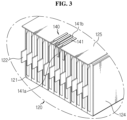
- FIG. 3 is an enlarged view of section A of FIG. 2 .
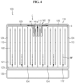
- FIG. 4 is a front view of the partially cutaway battery module shown in FIG. 2 .
- the battery module 100 includes a module case 110, a battery cell assembly 120, a heat sink 130 and a heat pipe member 140.
- the module case 110 forms an external appearance of the battery module 100, and may receive the battery cell assembly 120. To this end, the module case 110 may have a space for receiving the battery cell assembly 120.
- the module case 110 may come in various types and shapes, and in this embodiment, the module case 110 may include a top plate 111, a bottom plate 112 and a pair of side plates 113. This embodiment shows that the top plate 111, the bottom plate 112 and the side plates 113 are integrally formed, and is described taking it as an example.
- a bump pad 124 may be further provided between the side of the battery cell assembly 120 and the inner side surface of the module case 110, and a top cover 125 may be further provided between the upper surface of the battery cell assembly 120 and the inner upper surface of the module case 110.
- FIG. 2 one front side of the module case 110 is cut away to show the battery cell assembly 120, the bump pad 124 and the top cover 125 within the battery module 100 more clearly.
- the battery cell assembly 120 includes two or more battery cells 121.
- Each battery cell 121 may be a plate-shaped secondary battery.
- Each battery cell 121 may have an electrode lead 122 drawn to one or two sides.
- this embodiment takes a bidirectional battery having the electrode lead 122 drawn to two sides, i.e., in the opposite directions as an example, the battery cell may be a unidirectional battery having the electrode lead drawn to only one side.
- the battery cells 121 may be electrically connected to one another and stacked in the module case 110.
- each of the battery cells 121 may be stacked along the horizontal direction of the module case 110 such that the edge where the electrode lead 122 is not drawn is placed down. That is, the battery cells 121 may stand vertically such that the wide surface is not placed on the bottom and be stacked side by side to form the battery cell assembly 120.
- the electrode lead 122 may be placed on the left side and the right side of the battery cell assembly 120.
- the bump pad 124 can support the battery cell assembly 120 within the module case 110 more stably. At least one pair of bump pads 124 may be provided.
- the bump pad 124 may be made of an elastic material such as silicone pad.
- the pair of bump pads 124 are each disposed on two sides of the inner wall of the module case 110, i.e., inside of the side plates 113, to support two outermost sides of the battery cell assembly 120.
- the bump pad 124 may be further provided at each predetermined number of battery cells 121.
- the bump pad 124 plays a role in responding to swelling of the battery cells 121 and preventing the battery cell 121 from being damaged by external impacts.
- the heat sink 130 is configured to cool the battery cells 121, and may be mounted on one side of the module case 110.
- the heat sink 130 uses an edge cooling method and may be mounted below the module case 110 facing to the edges of the battery cells 121.
- the heat sink 130 may have a space in which a vapor or liquid refrigerant may flow, and have a metal outer wall that defines the space.
- the heat sink 130 is configured to cool the edge of each battery cell 121 where the electrode lead 122 is not drawn, in this embodiment, the bottom edge of each battery cell 121, and cools the side of each battery cell 121, not a wide surface, and by this reason, may be called a side cooling type structure.
- the heat sink 130 is mounted on one side of the battery cell assembly 120, in this embodiment, the bottom of the battery cell assembly 120, to cool one surface of the battery cell assembly 120, i.e., the bottom surface of the battery cell assembly 120.
- a thermally conductive adhesive 123 may be further included between the inner lower surface of the module case 110 and the lower side of the battery cell assembly 120.
- the thermally conductive adhesive 123 may fix the edges of the battery cells 121 to the inner lower surface of the module case 110 more stably.
- the thermally conductive adhesive 123 is interposed between the inner lower surface of the module case 110, i.e., the upper surface of the bottom plate 112 and the lower side of the battery cell assembly 120.
- the thermally conductive adhesive 123 is an adhesive for cooling that can conduct heat, and may include thermal resin.
- thermal resin There is no limitation on the type of the thermal resin, and for example, may be one of a thermally conductive silicone-based bond, a thermally conductive acrylic bond or a thermally conductive polyurethane bond.
- the thermally conductive adhesive 123 may be applied onto the inner lower surface of the module case 110 to stably fix the battery cell assembly 120 onto the inner lower surface of the module case 110 and improve thermal conductivity.
- the thermally conductive adhesive 123 and the heat sink 130 form a surface cooling structure having a sufficient contact area on the surface where the thermally conductive adhesive 123 and the heat sink 130 are in contact with the battery cell assembly 120.
- the bottom surface of the battery cell assembly 120 is cooled earlier by the heat sink 130.
- the battery module 100 basically has the heat sink 130 below the battery module 100 to cool the lower part of the battery cell assembly 120.
- the heat pipe member 140 is mounted inside the upper side of the module case 110. That is, the heat pipe member 140 is mounted above the battery cell assembly 120, in this embodiment, on top of the battery cell assembly 120, opposite the heat sink 130 mounted below the module case 110. Preferably, the heat pipe member 140 thermally contacts the inner upper side of the module case 110, i.e., the top plate 111.
- FIG. 5 shows the battery cells and the heat pipe member of FIG. 2 .
- FIG. 6 is an enlarged side view of the heat pipe member of FIG. 2 .
- the heat pipe member 140 uses a "thin fluid - filled heat pipe loop", and has a structure that causes a phase change of the refrigerant and spontaneous circulation of the refrigerant.
- the heat pipe member 140 may include a plurality of strip-shaped heat pipes 141.
- the heat pipe 141 includes the refrigerant in a case of sealed structure.
- the refrigerant is not forcibly circulated by a pump, and the refrigerant is spontaneously vaporized by heat generated from the battery cell 121 and condenses and circulates there.
- the refrigerant includes any type of refrigerant used in a cooler without limitation.
- the refrigerant may include, for example, ammonia, acetone, methanol and ethanol, and water may be used.
- the heat pipe 141 may further include therein a structure such as a wick to provide a movement path of the refrigerant. As clearly shown in FIG.
- each heat pipe 141 in each heat pipe 141, one side of the heat pipe 141, preferably an evaporator 141a is formed on the side of the electrode lead 122 of the battery cell 121, and the other side of the heat pipe 141, preferably a condenser 141b is applied to the side of the top of the battery cell 121.
- the heat pipe 141 may be in contact with the inner surface of the module case 110 on the upper side of the battery module 100, i.e., the top plate 111, to form a heat transfer pathway to the top of the module case 110.
- each heat pipe 141 may be bent, for example, in the shape of .
- the heat pipe 141 uses a "liquid-cooling system" of closed structure, thereby eliminating the need to add a separate refrigerant pump to the battery module 100. Accordingly, this cooling method does not need for mechanical operation as opposed to the forcible circulation method.
- the refrigerant is continuously provided from the condenser 141b to the evaporator 141a by the capillary force while circulating between the evaporator 141a and the condenser 141b, and vapor generated by a heat source of the evaporator 141a (the electrode lead 122 of the battery cell 121) moves to the condenser 141b and return to a liquid.
- the heat pipe 141 may be manufactured with a very small thickness, its structure may be designed to fit to a target application, and thus it is easy to be mounted in the battery module 100.
- the heat pipe 141 may be a minimum of 0.6 mm in thickness d1 at the evaporator 141a, and may be a minimum of 1.0 mm in thickness d2 at the condenser 141b, and it may be formed with a structure that is lightweight and has a high degree of freedom of design.
- the heat pipe 141 may be, for example, 30 mm in length l1 at the evaporator 141a, and may be, for example, 30 mm in length l2 at the condenser 141b.
- the heat pipe 141 is small and has good cooling effect. As the refrigerant goes through evaporation and condensation while moving in the closed circuit within the heat pipe 141, the heat pipe 141 effectively dissipates heat concentrated on the top left/right ends of the battery cell 121 through the module case 110. As shown in FIG.
- a pathway i.e., an additional heat transfer pathway SF through which heat goes away from the top left/right ends of the battery cell 121 through the upper side of the module case 110 is formed to reduce safety and durability risks caused by the increasing temperature difference in the battery cell 121.
- FIG. 7a shows the top cover of FIG. 2 .
- the top cover 125 has an insertion hole 126 for inserting the heat pipe 141 and a seating groove 127 for seating the condenser 141b of the heat pipe 141.
- the heat pipe 141 is assembled into the top cover 125.
- FIG. 7b is a top view of the heat pipe 141 of the heat pipe member 140, in particular, the condenser 141b, assembled into the top cover of FIG. 7a .
- an interference fit structure may be used.
- a protrusion 128 is formed on two sides of the insertion hole 126 at the location where the heat pipe 141 is bent in the shape of , to form a structure for firmly fixing the heat pipe 141.
- the protrusion 128 and the seating groove 127 may be spaced apart from each other to form a space for assembling the heat pipe member 140.
- the heat pipe 141 of the heat pipe member 140 in particular, the condenser 141b, may be in contact with the protrusion 128, and the evaporator 141a may be formed on the side of the electrode lead 122 of the battery cell 121.
- the heat pipe member 140 including the heat pipe 141 is assembled and mounted in the top cover 125, it is possible to firmly fix the heat pipe member 140, prevent the movement to the incorrect location caused by impacts and maintain the battery module 100 more firmly.
- the heat pipe member 140 is assembled on the side of the top cover 125, and in this instance, the condenser 141b is seated between the top cover 125 and the module case 110 to form a heat transfer pathway to the top.
- the top cover 125 may be a general plastic material or an engineering plastic material with higher thermal conductivity than the general plastic material, and thermal conductivity may be lower than the module case 110 of a metal material.
- a gap G may be formed between the upper surface of the battery cell assembly 120 and the top cover 125. Since a separate component (not shown) such as a voltage sensing line is disposed above the battery cell assembly 120, a space for the component is necessary, and it is desirable to form the gap G so as to cope with swelling of the battery cell 121 while the battery module 100 is in use. However, an air gap present in the gap G may provide a thermal insulation effect.
- the present disclosure further includes the heat pipe member 140.
- the heat transfer pathway MF of the battery cell assembly 120 is only formed toward the bottom of the battery module 100, but the present disclosure includes the heat pipe member 140 on top of the battery cell assembly 120, and as shown in FIG. 4 , the heat transfer pathway SF of the battery cell assembly 120 is also formed toward the top of the battery module 100.
- the present disclosure introduces the heat pipe member 140 on top of the battery cell assembly 120 and connects the heat pipe member 140 to the module case 110, and thus has a good effect of heat transfer from the battery cell assembly 120 to the module case 110 across the air gap having the thermal insulation effect.
- the heat pipe member 140 connected to the module case serves as a heat transfer bridge.
- the present disclosure further includes the heat pipe member 140 to reduce a temperature difference between one surface and the other surface of the battery cell assembly 120, i.e., a temperature difference between bottom and top, or a temperature difference between the lower surface and the upper surface.
- the heat pipe member 140 may be applied to an area that is difficult to be cooled by the heat sink 130, i.e., the upper surface of the battery cell assembly 120, in particular, a central part C where heat generation is severe.
- the heat pipe member 140 may be a single integrated plane-type heat pipe without including the plurality of strip-shaped heat pipes 141 as shown.
- Various embodiments of the heat pipe member 140 will be described below. In addition to assembly used in this embodiment, various embodiments are possible to facilitate the application of the heat pipe member 140 to the battery module 100, and its description will be provided below.
- the present disclosure is not limited to the type of the battery cell 121 included in the battery cell assembly 120, the number of battery cells 121 and the connection method, and the type of the module case 110 and its assembly method, but the battery cell 121, may be, in particular, a pouch-type battery cell as shown in FIG. 1 , and the module case 110 may include a tubular rectangular monoframe.
- the present disclosure will be described in more detail by describing the module case 110 and the assembly method of the battery module 100.
- the module case 110 has at least one open surface, through which the battery cell assembly 120 is inserted in.
- the module case 110 may be provided in a rectangular parallelepiped shape as a whole.
- the module case 110 may be provided in a tubular rectangular shape with two opposing open sides.
- the module case 110 is made of a thermally conductive material to absorb heat of the battery cell assembly 120 and dissipate the heat.
- the module case 110 may be made of a metal material. Because the metal material has good thermal conductivity, it is possible to perform the heat radiation function as a whole.
- all metal materials may be used, and when considering thermal conductivity, processing and cost, it is desirable to use SUS- or aluminum-based materials. The use of aluminum-based materials is more advantageous for light weight.
- the module case 110 may include the top plate 111 to cover the top of the battery cell assembly 120. To this end, the top plate 111 may have a sufficient size and shape to the top of the battery cell assembly 120.
- the module case 110 may include the bottom plate 112 opposite the top plate 111 to cover the bottom of the battery cell assembly 120.
- the bottom plate 112 is provided with generally the same shape as the top plate 111, and can stably support the battery cell assembly 120.
- the module case 110 may include the pair of side plates 113 coupled with the top plate 111 and the bottom plate 112 and disposed on two sides of the battery cell assembly 120. The pair of side plates 113 may have the same shape and size, facing each other.
- the module case 110 includes the top plate 111, the bottom plate 112 and the side plates 113, and has a first opening OA and a second opening OB on two sides of the lengthwise (L in FIG. 1 ) direction of the battery cell 121.
- the top plate 111, the bottom plate 112 and the side plates 113 may be connected to one another by welding.
- the top plate 111, the bottom plate 112 and the side plates 113 may be welded on the sides by friction stir welding such that their ends do not overlap and their edges come into contact with one another.
- the top plate 111, the bottom plate 112 and the side plates 113 may be bonded to one another, may be integrally formed, or may be coupled together with a hinge structure.
- the module case 110 may be a monoframe.
- a guide structure may be further formed on the upper surface of the bottom plate 112 to insert and fix the battery cell assembly 120.
- the guide structure and the battery cell assembly 120 may be coupled by a sliding method. That is, part of the battery cell assembly 120 may be inserted and coupled to the guide structure. For example, the edge of the battery cell 121 may be inserted into the guide structure.
- the guide structure may be provided in the shape of a groove in multiple numbers.
- the guide structure may be provided in the corresponding number to the number of battery cells 121.
- the battery cell assembly 120 is received in the module case 110 through the first opening OA of the module case 110.
- the battery cell assembly 120 may be received in the module case 110 with the thermally conductive adhesive 123 described with reference to FIG. 4 being applied below the battery cell assembly 120, and after the assembly process is completed, the thermally conductive adhesive 123 may be injected into the module case 110.
- the battery module 100 may further include other additional components of the battery module, for example, a sensing assembly.
- the electrode lead 122 of the battery cells 121 may be electrically connected to the sensing assembly.
- the sensing assembly may cover the front and rear sides of the battery cell assembly 120.
- the sensing assembly may be electrically connected to the battery cell assembly 120 to sense the voltage or temperature of the battery cell assembly 120. Additionally, the sensing assembly may be connected to an external power source.
- the sensing assembly plays a role in transmitting sensing information about the electrical properties of the battery cell assembly 120 such as voltage to other devices (not shown) outside of the battery module 100.
- a Battery Management System (BMS) may be connected to the battery module 100 to control the operation of the battery module 100 such as charging or discharging.
- the sensing assembly may be connected to the BMS to provide the sensed voltage information of the battery cell assembly 120 to the BMS, and the BMS may control the battery module 100 based on the information.
- BMS Battery Management System
- a front cover (not shown) is coupled to the first opening OA of the module case 110 and covers the front side of the battery cell assembly 120.
- the front cover may form a front side of the battery module 100.
- a rear cover (not shown) is coupled to the second opening OB of the module case 110 and covers the rear side of the battery cell assembly 120.
- the rear cover may form a rear side of the battery module 100.
- the front cover and the rear cover are placed on the front and rear sides of the top plate 111 and the bottom plate 112 to cover the front and rear sides of the battery cell assembly 120.
- the front cover and the rear cover may be welded or bonded to the module case 110.
- the front cover and the rear cover may be detachably coupled to the module case 110.
- the battery module 100 may use the tubular rectangular monoframe type module case 110, not the conventional cell cartridge. Due to not using the cell cartridge to which the edge of the battery cell is inserted and fixed by press-fit as conventionally, the allowance in the design of the entire battery module 100 increases, and it is possible to solve the conventional problem with the transmission, to the edge of the battery cell, of impacts or vibration which may occur during mounting when the edge of the battery cell is inserted into the cell cartridge.
- the battery module 100 and the battery pack including the same can protect the battery cell from external vibration very well, and thus they are advantageous in the application of vehicles that are frequently exposed to external vibration.
- the battery module 100 is completed by receiving the battery cell assembly 120 through the opening of the module case 110, followed by a simple operation of closing the openings on two sides. As described above, assembly of the battery module 100 can be easily performed, resulting in high process efficiency. Additionally, the battery module 100 may not include a sealing component such as an O-ring, a cooling component such as a cooling fin, or a reinforcing or fixing component such as a cartridge, reducing the number of components of the battery module 100. Accordingly, it is possible to reduce the production cost and time and the weight, thereby improving productivity of the battery module 100.
- a sealing component such as an O-ring
- a cooling component such as a cooling fin
- a reinforcing or fixing component such as a cartridge
- the second embodiment of the method of introducing the heat pipe 141 into the battery module 100 proposes a structure in which a plurality of heat pipes 141 is inserted into the top cover 125.
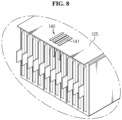
- FIG. 8 is a perspective view illustrating an embodiment of inserting the heat pipe member.
- the heat pipe 141 may be inserted into the top cover 125 through a method such as insert molding to manufacture an integrated structure, and this may be used when assembling the battery module 100.
- the heat pipe 141 is bent in the shape of , and a portion of the bent part is placed on the top cover 125 and contacts the module case 110, and other portion is placed on the side of the electrode leads of the battery cells within the battery cell assembly 120.
- FIG. 9 is a perspective view illustrating an embodiment in which the heat pipe member is formed as one block.
- FIG. 10 is a front view of the battery module to which the embodiment of FIG. 9 is applied.
- FIG. 11 is a perspective view showing the top cover including the heat pipe member of FIG. 9 .
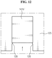
- FIG. 12 is a top view showing the top cover including the heat pipe member of FIG. 9 .
- the heat pipe member 140 includes the evaporator 141a in the shape of strips, and the condenser 141b' of an integrated heat pipe module.
- the heat pipe member 140 may be, for example, 4 mm in width w at the evaporator 141a.
- a distance p between the evaporators 141a may be, for example, 1.5 mm.
- the heat pipe member 140 may be a minimum of 1.0 mm in thickness d2 at the condenser 141b'.
- the top cover 125 has the insertion hole 126 for inserting the heat pipe condenser 141b' and the seating groove for seating the heat pipe condenser 141b' (in the same way as 127 in FIG. 7a ).
- the heat pipe member 140 is assembled into the top cover 125.
- an interference fit structure may be used.
- the protrusion 128 is formed on two sides of the insertion hole 126 at the location where the heat pipe member 140 is bent in the shape of , to form a structure for firmly fixing the heat pipe member 140.
- the heat pipe member 140 is assembled into the top cover 125, but also as in the embodiment described with reference to FIG. 8 , the heat pipe member 140 may be inserted into the top cover 125.
- the basic structure of cooling the lower side of the battery cell assembly 120 through the thermally conductive adhesive 123 or the heat sink 130 can also achieve cooling of the upper side through the heat pipe member 140.
- cooling through the upper side of the battery cell assembly 120 is possible, and thus it is easy to design devices using the battery module 100 or respond to design changes, and when cooling performance through the lower side of the battery cell assembly 120 is insufficient, it is possible to improve the cooling performance.
- the present disclosure can solve the problem with a temperature increase at the top left/right ends of the battery cell with the increasing length of the battery cell and its consequential large temperature difference between different locations in the battery cell. Since the temperature difference increase problem is prevented, it is possible to improve the safety and durability of the battery module 100 including the same.
- the present disclosure provides the battery module 100 of simple and compact design that does not make the entire structure complex and does not occupy a large space, and prevents a temperature difference from occurring between top and bottom of the battery cell assembly 120.
- the present disclosure further provides a battery pack including the battery module 100 and a vehicle including the battery pack.
- FIG. 13 is a diagram illustrating the battery pack according to an embodiment of the present disclosure.
- FIG. 14 is a diagram illustrating the vehicle according to an embodiment of the present disclosure.
- the battery pack 200 may include at least one battery module 100 according to the previous embodiment and a pack case 210 to package the at least one battery module 100. Additionally, in addition to the battery module 100 and the pack case 210, the battery pack 200 according to the present disclosure may further include various types of devices for controlling the charge/discharge of the battery module 100, for example, a BMS, a current sensor and a fuse.
- the battery pack 200 may be provided in the vehicle 300 as a fuel source of the vehicle 300.
- the battery pack 200 may be provided in the vehicle 300 such as an electric vehicle, a hybrid electric vehicle and other applications using the battery pack 200 as a fuel source.
- the vehicle 300 may be an electric vehicle.
- the battery pack 200 may be used as an electrical energy source to supply power to a motor of the electric vehicle 300 to drive the vehicle.
- the battery pack 200 has high nominal voltage of 100V or more.
- the battery pack 200 may be charged or discharged by the inverter by the operation of the motor and/or the internal combustion engine.
- the battery pack 200 may be charged by the regenerative charger coupled to the brake.
- the battery pack 200 may be electrically connected to the motor of the vehicle 300 through the inverter.
- the battery pack 200 includes a BMS.
- the BMS predicts the state of the battery cells in the battery pack 200, and manages the battery pack 200 using the predicted state information.
- the BMS predicts and manages the state information of the battery pack 200 such as State Of Charge (SOC), State Of Health (SOH), maximum allowable input/output power and output voltage of the battery pack 200.
- the BMS controls the charge or discharge of the battery pack 200 using the state information, and besides, may estimate when to replace the battery pack 200.
- the ECU is an electronic control device to control the state of the vehicle 300.
- the ECU determines torque information based on information of the accelerator, the brake and the speed, and controls the output of the motor according to the torque information.
- the ECU transmits a control signal to the inverter to allow the battery pack 200 to be charged or discharged based on the state information of the battery pack 200 including SOC and SOH received by the BMS.
- the inverter allows the battery pack 200 to be charged or discharged based on the control signal of the ECU.
- the motor drives the vehicle 300 based on the control information (for example, torque information) received from the ECU using electrical energy of the battery pack 200.
- the vehicle 300 includes the battery pack 200 according to the present disclosure, and as described above, the battery pack 200 may prevent the problem with a temperature increase at the top left/right ends of the battery cell with the increasing length of the battery cell and its consequential temperature difference between different locations in the battery cell. Accordingly, the battery pack 200 and the vehicle 300 including the same have improved safety and durability. Additionally, since the top cover is used to fix the heat pipe member, there is no likelihood that the fixed location is moved by external impacts. Accordingly, the structural stability of the battery pack 200 is maintained against vibrations applied to the battery pack 200 during driving of the vehicle 300, or impacts applied to the battery pack 200 in the event of collision of the vehicle 300, and external forces during the use of the vehicle 300 including the battery pack 200. Additionally, the battery pack 200 has good safety and long-term use, and thus the vehicle 300 including the same is safe and easy to operate.
- the battery pack 200 may be provided in any other device, apparatus and equipment such as Energy Storage Systems using secondary batteries other than the vehicle 300.
- the battery pack 200 according to this embodiment and the device, apparatus and equipment including the battery pack 200 such as the vehicle 300 include the above-described battery module 100, and thus it is possible to implement the battery pack 200 having all the above-described advantages of the battery module 100 and the device, apparatus and equipment such as the vehicle 300 including the battery pack 200.
- the battery module 100 with larger volume of the battery cells and more compact size and reduce a temperature difference between top and bottom of the battery cell assembly, the battery pack 200 including the battery module 100 and the vehicle 300 including the battery pack 200.
Landscapes
- Chemical & Material Sciences (AREA)
- Chemical Kinetics & Catalysis (AREA)
- Electrochemistry (AREA)
- General Chemical & Material Sciences (AREA)
- Engineering & Computer Science (AREA)
- Manufacturing & Machinery (AREA)
- Sustainable Development (AREA)
- Life Sciences & Earth Sciences (AREA)
- Inorganic Chemistry (AREA)
- Physics & Mathematics (AREA)
- Thermal Sciences (AREA)
- Mechanical Engineering (AREA)
- General Engineering & Computer Science (AREA)
- Aviation & Aerospace Engineering (AREA)
- Secondary Cells (AREA)
- Battery Mounting, Suspending (AREA)
- Sealing Battery Cases Or Jackets (AREA)
Description
- The present disclosure relates to a battery module, a battery pack comprising the battery module and a vehicle comprising the battery pack. The present application claims priority to
Korean Patent Application No. 10-2018-0109836 filed in the Republic of Korea on September 13, 2018 - Currently, commercially available secondary batteries include nickel-cadmium batteries, nickel-hydrogen batteries, nickel-zinc batteries, lithium secondary batteries and the like, and among them, lithium secondary batteries have little or no memory effect, and thus they are gaining more attention than nickel-based secondary batteries for their advantages that recharging can be done whenever it is convenient, the self-discharge rate is very low and the energy density is high. Recently, secondary batteries are not only commonly applied to small devices such as mobile electronic devices, but universally applied to medium- and large-sized devices including electric vehicles (EVs) that are driven by an electrical driving source such as plug-in electric vehicles (PEVs) and plug-in hybrid electric vehicles (PHEVs) and energy storage systems (ESSs).
- A unit secondary battery cell, or a unit battery cell usually has the working voltage of about 2.5V ~ 4.5V. Accordingly, in case that higher output voltage is required, a plurality of battery cells may be connected in series to form a battery pack. A battery pack may be formed by connecting a plurality of battery cells in parallel according to the charge/discharge capacity required for the battery pack. Accordingly, the number of battery cells included in the battery pack may be variously set depending on the output voltage or the charge/discharge capacity required. Particularly, pouch-type battery cells are commonly used in battery packs of medium- and large-sized devices due to their advantage of being easy to stack and lightweight.
-
FIG. 1 shows a general pouch-type battery cell. - The
battery cell 10 shown inFIG. 1 has a structure in which anelectrode assembly 14 having anelectrode lead 12 connected thereto is received in apouch case 16 together with an electrolyte solution, and thepouch case 16 is sealed through a sealing part S. Part of theelectrode lead 12 is exposed through thepouch case 16, and the exposedelectrode lead 12 is electrically connected to a device in which thebattery cell 10 is mounted, or is used to electrically connect thebattery cells 10. - To form a battery pack by connecting the
battery cells 10 in series/in parallel, generally, a battery cell assembly including at least onebattery cell 10 is made and used to form a battery module, and then other components are added to at least one battery module. - In the battery module, with the increasing battery capacity required, the importance of technology for efficiently cooling heat generated from the
battery cells 10 is gradually increasing, and there is a tendency to prefer an edge cooling method using a heat sink mounted on the bottom of the module case of the battery module. - The edge cooling type battery module is cooled by transferring heat generated from the battery cells to the heat sink on the bottom of the module case, but does not have a heat transfer pathway to the top of the module case. Accordingly, the conventional battery module has a large temperature difference between top and bottom of the battery cell assembly.
- Particularly, recently, the development trend of the battery module for electric vehicles moves toward increasing the length L of the
battery cell 10. When only the lower part LP of thebattery cell 10 is cooled through an edge cooling method, as the electric current becomes concentrated near theelectrode lead 12, thelong battery cell 10 has a temperature increase at the top left/right ends UP of thebattery cell 10, and as a consequence, there is a large temperature difference between different locations in thesame battery cell 10. Accordingly, there are safety and durability problems of the battery module including the same, and their solutions are necessary. - Further prior art is described in
KR 2017 0070795 A KR 2014 0144330 A KR 2016 0122444 A KR 2017 0019229 A JP 2015 528 189 A DE 102015219536A1 . - Accordingly, the present invention is designed to solve the above-described problem, and the present disclosure is directed to providing a battery module with a reduced temperature difference between top and bottom of a battery cell assembly, a battery pack comprising the battery module and a vehicle comprising the battery pack.
- These and other objects and advantages of the present invention will be understood by the following description and will be apparent from the embodiments of the present invention.
- Further, it will be readily understood that the objects and advantages of the present invention are realized by the means set forth in the appended claims and combinations thereof.
- The invention is as defined in independent claim 1. Preferred embodiments are as defined in the dependent claims. To achieve the above-described object, the present invention provides a battery module including a module case, a battery cell assembly that is received in the module case, the battery cell assembly including battery cells, wherein each of the battery cells has an electrode lead drawn to one or two sides, the battery cells are stacked along a horizontal direction of the module case such that an edge where the electrode lead is not drawn is placed down, a heat sink mounted below the module case, facing the edges of the battery cells, and a heat pipe member mounted inside an upper side of the module case, wherein the heat pipe member includes an evaporator and a condenser, wherein a top cover is provided between the upper side of the module case and the battery cell assembly, wherein the heat pipe member is mounted in the top cover, and the evaporator is formed on a side of the electrode leads of the battery cells, and the condenser is in contact with an inner surface of the module case, wherein the evaporator is formed on the side of the electrode leads of the battery cells and the condenser is seated between the top cover and the module case to form a heat transfer pathway to the top.
- The battery module may further include a thermally conductive adhesive interposed between an inner lower surface of the module case and a lower side of the battery cell assembly.
- The module case may further include a top plate that covers an upper side of the battery cell assembly, a bottom plate that is disposed opposite the top plate and covers a lower side of the battery cell assembly, a pair of side plates that are coupled to the top plate and the bottom plate and disposed on two sides of the battery cell assembly, a first opening and a second opening that are open to two sides of lengthwise direction of the battery cells, a front cover that is coupled to the first opening of the module case and covers a front side of the battery cell assembly, and a rear cover that is coupled to the second opening of the module case and covers a rear side of the battery cell assembly.
- The heat pipe member may be assembled into the top cover by an interference fit structure.
- The heat pipe member may include a plurality of strip-shaped heat pipes. In the heat pipe member, the evaporator may be in a shape of a plurality of strips, and the condenser may use an integrated heat pipe module.
- The present invention further provides a battery pack including at least one battery module according to the present invention, and a pack case that packages the at least one battery module.
- The present invention further provides a vehicle including at least one battery pack according to the present invention.
- According to an aspect of the present invention, it is possible to effectively transfer heat from the upper side of the battery cell assembly to the module case. Accordingly, a structure that cools the lower side of the battery cell assembly through a thermally conductive adhesive or a heat sink can also achieve cooling through the upper side of the battery cell assembly. According to the present invention, since cooling through the upper side of the battery cell assembly is possible, it is possible to reduce the occurrence of a temperature difference between top and bottom of the battery cell. Even when the cooling performance through the lower side of the battery cell assembly is insufficient, it is possible to prevent the heat accumulation in the battery module through improved cooling performance through the upper side of the battery cell assembly.
- According to another aspect of the present disclosure, the heat pipe member is mounted on the top cover, thereby firmly fixing the heat pipe member, preventing the movement to the incorrect location caused by impacts and maintaining the battery module more firmly.
- According to still another aspect of the present disclosure, there is provided a battery module using a tubular rectangular monoframe type module case, not a cell cartridge as conventionally. Due to not using the cell cartridge to which the edge of the battery cell is inserted and fixed by press-fit as conventionally, the allowance in the design of the entire battery module increases, and it is possible to solve the conventional problem with the transmission, to the edge of the battery cell, of impacts or vibration that may occur during mounting when the edge of the battery cell is inserted into the cell cartridge. The battery module and the battery pack can protect the battery cell from external vibration very well, and thus they are advantageous in the application of vehicles that are frequently exposed to external vibration.
- According to yet another aspect of the present disclosure, assembly of the battery module can be easily performed, resulting in high process efficiency. Additionally, the battery module may not include a sealing component such as an O-ring, a cooling component such as a cooling fin, or a reinforcing or fixing component such as a cartridge, reducing the number of components of the battery module. Accordingly, according to this aspect of the present disclosure, it is possible to reduce the production cost and time and the weight, thereby improving productivity of the battery module.
- As described above, the present disclosure can provide a simple and compact battery module that does not make the entire structure complex, does not occupy a large space and reduces a temperature difference between the top and bottom of the battery cell assembly. Further, the present disclosure can provide a battery pack including the battery module and a vehicle including the battery pack.
- Particularly, according to the present disclosure, the battery module configured to cool the bottom of the battery cell through an edge cooling method can reduce a temperature difference between different locations in the same battery cell caused by the increasing length of the battery cell in the battery module. Accordingly, it is possible to improve the safety and durability of the battery module, the battery pack and the vehicle including the same.
- The accompanying drawings illustrate a preferred embodiment of the present disclosure, and together with the detailed description of the present disclosure described below, serve to provide a further understanding of the technical aspects of the present disclosure, and thus the present disclosure should not be construed as being limited to the drawings.
-
FIG. 1 shows a general pouch-type battery cell. -
FIG. 2 is a partial cutaway perspective view illustrating a battery module according to an embodiment of the present invention. -
FIG. 3 is an enlarged view of section A ofFIG. 2 . -
FIG. 4 is a front view of the partially cutaway battery module shown inFIG. 2 . -
FIG. 5 shows battery cells and a heat pipe member ofFIG. 2 . -
FIG. 6 is an enlarged side view of a heat pipe member ofFIG. 2 . -
FIG. 7a shows a top cover part ofFIG. 2 . -
FIG. 7b is a top view of a heat pipe member assembled into the top cover ofFIG. 7a . -
FIG. 8 is a perspective view illustrating an embodiment of inserting a heat pipe member. -
FIG. 9 is a perspective view illustrating an embodiment in which a heat pipe member is formed as one block. -
FIG. 10 is a front view of a battery module to which the embodiment ofFIG. 9 is applied. -
FIG. 11 is a perspective view showing a top cover including the heat pipe member ofFIG. 9 . -
FIG. 12 is a top view showing a top cover including the heat pipe member ofFIG. 9 . -
FIG. 13 is a diagram illustrating a battery pack according to an embodiment of the present disclosure. -
FIG. 14 is a diagram illustrating a vehicle according to an embodiment of the present disclosure. - Hereinafter, the preferred embodiments of the present disclosure will be described in detail with reference to the accompanying drawings.
-
FIG. 2 is a partial cutaway perspective view illustrating a battery module according to an embodiment of the present disclosure.FIG. 3 is an enlarged view of section A ofFIG. 2 .FIG. 4 is a front view of the partially cutaway battery module shown inFIG. 2 . - First, referring to
FIG. 2 , thebattery module 100 includes amodule case 110, abattery cell assembly 120, aheat sink 130 and aheat pipe member 140. - The
module case 110 forms an external appearance of thebattery module 100, and may receive thebattery cell assembly 120. To this end, themodule case 110 may have a space for receiving thebattery cell assembly 120. Themodule case 110 may come in various types and shapes, and in this embodiment, themodule case 110 may include atop plate 111, abottom plate 112 and a pair ofside plates 113. This embodiment shows that thetop plate 111, thebottom plate 112 and theside plates 113 are integrally formed, and is described taking it as an example. - Further referring to
FIG. 3 , in this embodiment, abump pad 124 may be further provided between the side of thebattery cell assembly 120 and the inner side surface of themodule case 110, and atop cover 125 may be further provided between the upper surface of thebattery cell assembly 120 and the inner upper surface of themodule case 110. InFIG. 2 , one front side of themodule case 110 is cut away to show thebattery cell assembly 120, thebump pad 124 and thetop cover 125 within thebattery module 100 more clearly. - As shown in
FIGS. 2 and3 , thebattery cell assembly 120 includes two ormore battery cells 121. Eachbattery cell 121 may be a plate-shaped secondary battery. Eachbattery cell 121 may have anelectrode lead 122 drawn to one or two sides. Although this embodiment takes a bidirectional battery having theelectrode lead 122 drawn to two sides, i.e., in the opposite directions as an example, the battery cell may be a unidirectional battery having the electrode lead drawn to only one side. - The
battery cells 121 may be electrically connected to one another and stacked in themodule case 110. In detail, each of thebattery cells 121 may be stacked along the horizontal direction of themodule case 110 such that the edge where theelectrode lead 122 is not drawn is placed down. That is, thebattery cells 121 may stand vertically such that the wide surface is not placed on the bottom and be stacked side by side to form thebattery cell assembly 120. In this instance, theelectrode lead 122 may be placed on the left side and the right side of thebattery cell assembly 120. - As shown in
FIGS. 3 and4 , thebump pad 124 can support thebattery cell assembly 120 within themodule case 110 more stably. At least one pair ofbump pads 124 may be provided. Thebump pad 124 may be made of an elastic material such as silicone pad. The pair ofbump pads 124 are each disposed on two sides of the inner wall of themodule case 110, i.e., inside of theside plates 113, to support two outermost sides of thebattery cell assembly 120. Thebump pad 124 may be further provided at each predetermined number ofbattery cells 121. Thebump pad 124 plays a role in responding to swelling of thebattery cells 121 and preventing thebattery cell 121 from being damaged by external impacts. - Referring to
FIGS. 2 and4 together, theheat sink 130 is configured to cool thebattery cells 121, and may be mounted on one side of themodule case 110. Theheat sink 130 uses an edge cooling method and may be mounted below themodule case 110 facing to the edges of thebattery cells 121. Theheat sink 130 may have a space in which a vapor or liquid refrigerant may flow, and have a metal outer wall that defines the space. - The
heat sink 130 is configured to cool the edge of eachbattery cell 121 where theelectrode lead 122 is not drawn, in this embodiment, the bottom edge of eachbattery cell 121, and cools the side of eachbattery cell 121, not a wide surface, and by this reason, may be called a side cooling type structure. Theheat sink 130 is mounted on one side of thebattery cell assembly 120, in this embodiment, the bottom of thebattery cell assembly 120, to cool one surface of thebattery cell assembly 120, i.e., the bottom surface of thebattery cell assembly 120. - As shown in
FIG. 4 , a thermally conductive adhesive 123 may be further included between the inner lower surface of themodule case 110 and the lower side of thebattery cell assembly 120. The thermally conductive adhesive 123 may fix the edges of thebattery cells 121 to the inner lower surface of themodule case 110 more stably. - The thermally
conductive adhesive 123 is interposed between the inner lower surface of themodule case 110, i.e., the upper surface of thebottom plate 112 and the lower side of thebattery cell assembly 120. The thermallyconductive adhesive 123 is an adhesive for cooling that can conduct heat, and may include thermal resin. There is no limitation on the type of the thermal resin, and for example, may be one of a thermally conductive silicone-based bond, a thermally conductive acrylic bond or a thermally conductive polyurethane bond. - The thermally conductive adhesive 123 may be applied onto the inner lower surface of the
module case 110 to stably fix thebattery cell assembly 120 onto the inner lower surface of themodule case 110 and improve thermal conductivity. The thermallyconductive adhesive 123 and theheat sink 130 form a surface cooling structure having a sufficient contact area on the surface where the thermallyconductive adhesive 123 and theheat sink 130 are in contact with thebattery cell assembly 120. The bottom surface of thebattery cell assembly 120 is cooled earlier by theheat sink 130. As described above, thebattery module 100 basically has theheat sink 130 below thebattery module 100 to cool the lower part of thebattery cell assembly 120. - As shown in
FIGS. 1 to 4 , theheat pipe member 140 is mounted inside the upper side of themodule case 110. That is, theheat pipe member 140 is mounted above thebattery cell assembly 120, in this embodiment, on top of thebattery cell assembly 120, opposite theheat sink 130 mounted below themodule case 110. Preferably, theheat pipe member 140 thermally contacts the inner upper side of themodule case 110, i.e., thetop plate 111. -
FIG. 5 shows the battery cells and the heat pipe member ofFIG. 2 .FIG. 6 is an enlarged side view of the heat pipe member ofFIG. 2 . - In
FIGS. 1 to 6 , theheat pipe member 140 uses a "thin fluid - filled heat pipe loop", and has a structure that causes a phase change of the refrigerant and spontaneous circulation of the refrigerant. Theheat pipe member 140 may include a plurality of strip-shapedheat pipes 141. - The
heat pipe 141 includes the refrigerant in a case of sealed structure. The refrigerant is not forcibly circulated by a pump, and the refrigerant is spontaneously vaporized by heat generated from thebattery cell 121 and condenses and circulates there. The refrigerant includes any type of refrigerant used in a cooler without limitation. The refrigerant may include, for example, ammonia, acetone, methanol and ethanol, and water may be used. Additionally, theheat pipe 141 may further include therein a structure such as a wick to provide a movement path of the refrigerant. As clearly shown inFIG. 5 , in eachheat pipe 141, one side of theheat pipe 141, preferably anevaporator 141a is formed on the side of theelectrode lead 122 of thebattery cell 121, and the other side of theheat pipe 141, preferably acondenser 141b is applied to the side of the top of thebattery cell 121. In particular, theheat pipe 141 may be in contact with the inner surface of themodule case 110 on the upper side of thebattery module 100, i.e., thetop plate 111, to form a heat transfer pathway to the top of themodule case 110. For this configuration, eachheat pipe 141 may be bent, for example, in the shape of.
- In this embodiment, the
heat pipe 141 uses a "liquid-cooling system" of closed structure, thereby eliminating the need to add a separate refrigerant pump to thebattery module 100. Accordingly, this cooling method does not need for mechanical operation as opposed to the forcible circulation method. The refrigerant is continuously provided from thecondenser 141b to theevaporator 141a by the capillary force while circulating between the evaporator 141a and thecondenser 141b, and vapor generated by a heat source of the evaporator 141a (theelectrode lead 122 of the battery cell 121) moves to thecondenser 141b and return to a liquid. - The
heat pipe 141 may be manufactured with a very small thickness, its structure may be designed to fit to a target application, and thus it is easy to be mounted in thebattery module 100. InFIG. 6 , it is possible to form a structure that is thin, and for example, theheat pipe 141 may be a minimum of 0.6 mm in thickness d1 at theevaporator 141a, and may be a minimum of 1.0 mm in thickness d2 at thecondenser 141b, and it may be formed with a structure that is lightweight and has a high degree of freedom of design. Theheat pipe 141 may be, for example, 30 mm in length l1 at theevaporator 141a, and may be, for example, 30 mm in length l2 at thecondenser 141b. Theheat pipe 141 is small and has good cooling effect. As the refrigerant goes through evaporation and condensation while moving in the closed circuit within theheat pipe 141, theheat pipe 141 effectively dissipates heat concentrated on the top left/right ends of thebattery cell 121 through themodule case 110. As shown inFIG. 4 , a pathway (bridge), i.e., an additional heat transfer pathway SF through which heat goes away from the top left/right ends of thebattery cell 121 through the upper side of themodule case 110 is formed to reduce safety and durability risks caused by the increasing temperature difference in thebattery cell 121. - Various embodiments are possible to facilitate the application of the
heat pipe member 140 to thebattery module 100. In particular, in this embodiment, theheat pipe member 140 is assembled into thetop cover 125 and mounted in thebattery module 100 to form a heat transfer pathway from theheat pipe member 140 to themodule case 110.FIG. 7a shows the top cover ofFIG. 2 . - As shown in
FIG. 7a , thetop cover 125 has aninsertion hole 126 for inserting theheat pipe 141 and aseating groove 127 for seating thecondenser 141b of theheat pipe 141. In the assembling, when theheat pipe 141 is inserted into theinsertion hole 126 in the direction of the arrow and thecondenser 141b is positioned in theseating groove 127, theheat pipe 141 is assembled into thetop cover 125.FIG. 7b is a top view of theheat pipe 141 of theheat pipe member 140, in particular, thecondenser 141b, assembled into the top cover ofFIG. 7a . - In this instance, an interference fit structure may be used. Additionally, a
protrusion 128 is formed on two sides of theinsertion hole 126 at the location where theheat pipe 141 is bent in the shape of, to form a structure for firmly fixing the
heat pipe 141. As can be seen inFIG. 7a , theprotrusion 128 and theseating groove 127 may be spaced apart from each other to form a space for assembling theheat pipe member 140. When theheat pipe member 140 is assembled thereon, as shown inFIG. 7b , theheat pipe 141 of theheat pipe member 140, in particular, thecondenser 141b, may be in contact with theprotrusion 128, and theevaporator 141a may be formed on the side of theelectrode lead 122 of thebattery cell 121. - As described above, when the
heat pipe member 140 including theheat pipe 141 is assembled and mounted in thetop cover 125, it is possible to firmly fix theheat pipe member 140, prevent the movement to the incorrect location caused by impacts and maintain thebattery module 100 more firmly. - As described above, in this embodiment, the
heat pipe member 140 is assembled on the side of thetop cover 125, and in this instance, thecondenser 141b is seated between thetop cover 125 and themodule case 110 to form a heat transfer pathway to the top. - The
top cover 125 may be a general plastic material or an engineering plastic material with higher thermal conductivity than the general plastic material, and thermal conductivity may be lower than themodule case 110 of a metal material. As clearly shown inFIGS. 4 and6 , a gap G may be formed between the upper surface of thebattery cell assembly 120 and thetop cover 125. Since a separate component (not shown) such as a voltage sensing line is disposed above thebattery cell assembly 120, a space for the component is necessary, and it is desirable to form the gap G so as to cope with swelling of thebattery cell 121 while thebattery module 100 is in use. However, an air gap present in the gap G may provide a thermal insulation effect. - Since the electric current becomes concentrated near the
electrode lead 122, much heat is generated from thebattery cell 121. The heat generated from thebattery cell 121 tends to be dissipated in all direction, but the air gap present in the gap G and thetop cover 125 block the heat, and thus heat dissipation to the top of thebattery cell assembly 120 may be difficult. Accordingly, a heat transfer pathway MF is formed toward the bottom of thebattery cell assembly 120 by theheat sink 130 as indicated by the arrow inFIG. 4 , and tendency toward dissipation through the bottom of themodule case 110 via the thermallyconductive adhesive 123 is dominant. The present disclosure further includes theheat pipe member 140. When there is noheat pipe member 140, the heat transfer pathway MF of thebattery cell assembly 120 is only formed toward the bottom of thebattery module 100, but the present disclosure includes theheat pipe member 140 on top of thebattery cell assembly 120, and as shown inFIG. 4 , the heat transfer pathway SF of thebattery cell assembly 120 is also formed toward the top of thebattery module 100. The present disclosure introduces theheat pipe member 140 on top of thebattery cell assembly 120 and connects theheat pipe member 140 to themodule case 110, and thus has a good effect of heat transfer from thebattery cell assembly 120 to themodule case 110 across the air gap having the thermal insulation effect. In thebattery module 100 of the present disclosure, theheat pipe member 140 connected to the module case serves as a heat transfer bridge. - If there is no
heat pipe member 140, only the lower part of thebattery cell assembly 120 is cooled by theheat sink 130, and thus a temperature difference between top and bottom of thebattery cell assembly 120 will increase. The present disclosure further includes theheat pipe member 140 to reduce a temperature difference between one surface and the other surface of thebattery cell assembly 120, i.e., a temperature difference between bottom and top, or a temperature difference between the lower surface and the upper surface. - The
heat pipe member 140 may be applied to an area that is difficult to be cooled by theheat sink 130, i.e., the upper surface of thebattery cell assembly 120, in particular, a central part C where heat generation is severe. Theheat pipe member 140 may be a single integrated plane-type heat pipe without including the plurality of strip-shapedheat pipes 141 as shown. Various embodiments of theheat pipe member 140 will be described below. In addition to assembly used in this embodiment, various embodiments are possible to facilitate the application of theheat pipe member 140 to thebattery module 100, and its description will be provided below. - The present disclosure is not limited to the type of the
battery cell 121 included in thebattery cell assembly 120, the number ofbattery cells 121 and the connection method, and the type of themodule case 110 and its assembly method, but thebattery cell 121, may be, in particular, a pouch-type battery cell as shown inFIG. 1 , and themodule case 110 may include a tubular rectangular monoframe. Hereinafter, the present disclosure will be described in more detail by describing themodule case 110 and the assembly method of thebattery module 100. - Referring back to
FIG. 2 , themodule case 110 has at least one open surface, through which thebattery cell assembly 120 is inserted in. Themodule case 110 may be provided in a rectangular parallelepiped shape as a whole. For example, themodule case 110 may be provided in a tubular rectangular shape with two opposing open sides. Themodule case 110 is made of a thermally conductive material to absorb heat of thebattery cell assembly 120 and dissipate the heat. Themodule case 110 may be made of a metal material. Because the metal material has good thermal conductivity, it is possible to perform the heat radiation function as a whole. For the material of themodule case 110, all metal materials may be used, and when considering thermal conductivity, processing and cost, it is desirable to use SUS- or aluminum-based materials. The use of aluminum-based materials is more advantageous for light weight. - The
module case 110 may include thetop plate 111 to cover the top of thebattery cell assembly 120. To this end, thetop plate 111 may have a sufficient size and shape to the top of thebattery cell assembly 120. Themodule case 110 may include thebottom plate 112 opposite thetop plate 111 to cover the bottom of thebattery cell assembly 120. Thebottom plate 112 is provided with generally the same shape as thetop plate 111, and can stably support thebattery cell assembly 120. Themodule case 110 may include the pair ofside plates 113 coupled with thetop plate 111 and thebottom plate 112 and disposed on two sides of thebattery cell assembly 120. The pair ofside plates 113 may have the same shape and size, facing each other. - As described above, the
module case 110 includes thetop plate 111, thebottom plate 112 and theside plates 113, and has a first opening OA and a second opening OB on two sides of the lengthwise (L inFIG. 1 ) direction of thebattery cell 121. Thetop plate 111, thebottom plate 112 and theside plates 113 may be connected to one another by welding. In an example, thetop plate 111, thebottom plate 112 and theside plates 113 may be welded on the sides by friction stir welding such that their ends do not overlap and their edges come into contact with one another. In another example, thetop plate 111, thebottom plate 112 and theside plates 113 may be bonded to one another, may be integrally formed, or may be coupled together with a hinge structure. As described above, themodule case 110 may be a monoframe. - A guide structure may be further formed on the upper surface of the
bottom plate 112 to insert and fix thebattery cell assembly 120. The guide structure and thebattery cell assembly 120 may be coupled by a sliding method. That is, part of thebattery cell assembly 120 may be inserted and coupled to the guide structure. For example, the edge of thebattery cell 121 may be inserted into the guide structure. The guide structure may be provided in the shape of a groove in multiple numbers. The guide structure may be provided in the corresponding number to the number ofbattery cells 121. When thebattery cell 121 is inserted into the guide structure, it is possible to support thebattery cell 121 more stably. - In the assembly process, the
battery cell assembly 120 is received in themodule case 110 through the first opening OA of themodule case 110. In this instance, thebattery cell assembly 120 may be received in themodule case 110 with the thermally conductive adhesive 123 described with reference toFIG. 4 being applied below thebattery cell assembly 120, and after the assembly process is completed, the thermally conductive adhesive 123 may be injected into themodule case 110. - The
battery module 100 may further include other additional components of the battery module, for example, a sensing assembly. Theelectrode lead 122 of thebattery cells 121 may be electrically connected to the sensing assembly. The sensing assembly may cover the front and rear sides of thebattery cell assembly 120. The sensing assembly may be electrically connected to thebattery cell assembly 120 to sense the voltage or temperature of thebattery cell assembly 120. Additionally, the sensing assembly may be connected to an external power source. The sensing assembly plays a role in transmitting sensing information about the electrical properties of thebattery cell assembly 120 such as voltage to other devices (not shown) outside of thebattery module 100. For example, a Battery Management System (BMS) may be connected to thebattery module 100 to control the operation of thebattery module 100 such as charging or discharging. In this instance, the sensing assembly may be connected to the BMS to provide the sensed voltage information of thebattery cell assembly 120 to the BMS, and the BMS may control thebattery module 100 based on the information. - After the
battery cell assembly 120 is received in themodule case 110, a front cover (not shown) is coupled to the first opening OA of themodule case 110 and covers the front side of thebattery cell assembly 120. The front cover may form a front side of thebattery module 100. After thebattery cell assembly 120 is received in themodule case 110, a rear cover (not shown) is coupled to the second opening OB of themodule case 110 and covers the rear side of thebattery cell assembly 120. The rear cover may form a rear side of thebattery module 100. - As described above, the front cover and the rear cover are placed on the front and rear sides of the
top plate 111 and thebottom plate 112 to cover the front and rear sides of thebattery cell assembly 120. The front cover and the rear cover may be welded or bonded to themodule case 110. Alternatively, the front cover and the rear cover may be detachably coupled to themodule case 110. - As described above, the
battery module 100 may use the tubular rectangular monoframetype module case 110, not the conventional cell cartridge. Due to not using the cell cartridge to which the edge of the battery cell is inserted and fixed by press-fit as conventionally, the allowance in the design of theentire battery module 100 increases, and it is possible to solve the conventional problem with the transmission, to the edge of the battery cell, of impacts or vibration which may occur during mounting when the edge of the battery cell is inserted into the cell cartridge. Thebattery module 100 and the battery pack including the same can protect the battery cell from external vibration very well, and thus they are advantageous in the application of vehicles that are frequently exposed to external vibration. - Additionally, the
battery module 100 is completed by receiving thebattery cell assembly 120 through the opening of themodule case 110, followed by a simple operation of closing the openings on two sides. As described above, assembly of thebattery module 100 can be easily performed, resulting in high process efficiency. Additionally, thebattery module 100 may not include a sealing component such as an O-ring, a cooling component such as a cooling fin, or a reinforcing or fixing component such as a cartridge, reducing the number of components of thebattery module 100. Accordingly, it is possible to reduce the production cost and time and the weight, thereby improving productivity of thebattery module 100. - The second embodiment of the method of introducing the
heat pipe 141 into thebattery module 100 proposes a structure in which a plurality ofheat pipes 141 is inserted into thetop cover 125.FIG. 8 is a perspective view illustrating an embodiment of inserting the heat pipe member. When manufacturing thetop cover 125, theheat pipe 141 may be inserted into thetop cover 125 through a method such as insert molding to manufacture an integrated structure, and this may be used when assembling thebattery module 100. Also in this embodiment, theheat pipe 141 is bent in the shape of, and a portion of the bent part is placed on the
top cover 125 and contacts themodule case 110, and other portion is placed on the side of the electrode leads of the battery cells within thebattery cell assembly 120. - The third embodiment proposes a structure in which the heat pipe is modularized (as a block) and assembled into the
top cover 125.FIG. 9 is a perspective view illustrating an embodiment in which the heat pipe member is formed as one block.FIG. 10 is a front view of the battery module to which the embodiment ofFIG. 9 is applied.FIG. 11 is a perspective view showing the top cover including the heat pipe member ofFIG. 9 .FIG. 12 is a top view showing the top cover including the heat pipe member ofFIG. 9 . - Referring to
FIGS. 9 to 12 , theheat pipe member 140 includes theevaporator 141a in the shape of strips, and thecondenser 141b' of an integrated heat pipe module. Theheat pipe member 140 may be, for example, 4 mm in width w at theevaporator 141a. A distance p between theevaporators 141a may be, for example, 1.5 mm. Theheat pipe member 140 may be a minimum of 1.0 mm in thickness d2 at thecondenser 141b'. - As shown in
FIG. 12 , thetop cover 125 has theinsertion hole 126 for inserting theheat pipe condenser 141b' and the seating groove for seating theheat pipe condenser 141b' (in the same way as 127 inFIG. 7a ). In the assembling, when theheat pipe condenser 141b' is inserted into theinsertion hole 126 in the direction of the arrow and thecondenser 141b' is positioned in the seating groove, theheat pipe member 140 is assembled into thetop cover 125. In this instance, an interference fit structure may be used. Additionally, theprotrusion 128 is formed on two sides of theinsertion hole 126 at the location where theheat pipe member 140 is bent in the shape of, to form a structure for firmly fixing the
heat pipe member 140. - As in the embodiments described with reference to
FIGS. 2 to FIGS. 7a and7b , an example is shown in which theheat pipe member 140 is assembled into thetop cover 125, but also as in the embodiment described with reference toFIG. 8 , theheat pipe member 140 may be inserted into thetop cover 125. - In the embodiments described hereinabove, the basic structure of cooling the lower side of the
battery cell assembly 120 through the thermally conductive adhesive 123 or theheat sink 130 can also achieve cooling of the upper side through theheat pipe member 140. According to the present disclosure, cooling through the upper side of thebattery cell assembly 120 is possible, and thus it is easy to design devices using thebattery module 100 or respond to design changes, and when cooling performance through the lower side of thebattery cell assembly 120 is insufficient, it is possible to improve the cooling performance. - In particular, as mentioned in
FIG. 1 , the present disclosure can solve the problem with a temperature increase at the top left/right ends of the battery cell with the increasing length of the battery cell and its consequential large temperature difference between different locations in the battery cell. Since the temperature difference increase problem is prevented, it is possible to improve the safety and durability of thebattery module 100 including the same. - As described above, the present disclosure provides the
battery module 100 of simple and compact design that does not make the entire structure complex and does not occupy a large space, and prevents a temperature difference from occurring between top and bottom of thebattery cell assembly 120. The present disclosure further provides a battery pack including thebattery module 100 and a vehicle including the battery pack. -
FIG. 13 is a diagram illustrating the battery pack according to an embodiment of the present disclosure.FIG. 14 is a diagram illustrating the vehicle according to an embodiment of the present disclosure. - Referring to
FIGS. 13 and14 , thebattery pack 200 may include at least onebattery module 100 according to the previous embodiment and apack case 210 to package the at least onebattery module 100. Additionally, in addition to thebattery module 100 and thepack case 210, thebattery pack 200 according to the present disclosure may further include various types of devices for controlling the charge/discharge of thebattery module 100, for example, a BMS, a current sensor and a fuse. - The
battery pack 200 may be provided in thevehicle 300 as a fuel source of thevehicle 300. For example, thebattery pack 200 may be provided in thevehicle 300 such as an electric vehicle, a hybrid electric vehicle and other applications using thebattery pack 200 as a fuel source. - Preferably, the
vehicle 300 may be an electric vehicle. Thebattery pack 200 may be used as an electrical energy source to supply power to a motor of theelectric vehicle 300 to drive the vehicle. In this case, thebattery pack 200 has high nominal voltage of 100V or more. - The
battery pack 200 may be charged or discharged by the inverter by the operation of the motor and/or the internal combustion engine. Thebattery pack 200 may be charged by the regenerative charger coupled to the brake. Thebattery pack 200 may be electrically connected to the motor of thevehicle 300 through the inverter. - As described above, the
battery pack 200 includes a BMS. The BMS predicts the state of the battery cells in thebattery pack 200, and manages thebattery pack 200 using the predicted state information. For example, the BMS predicts and manages the state information of thebattery pack 200 such as State Of Charge (SOC), State Of Health (SOH), maximum allowable input/output power and output voltage of thebattery pack 200. Additionally, the BMS controls the charge or discharge of thebattery pack 200 using the state information, and besides, may estimate when to replace thebattery pack 200. - The ECU is an electronic control device to control the state of the
vehicle 300. For example, the ECU determines torque information based on information of the accelerator, the brake and the speed, and controls the output of the motor according to the torque information. Additionally, the ECU transmits a control signal to the inverter to allow thebattery pack 200 to be charged or discharged based on the state information of thebattery pack 200 including SOC and SOH received by the BMS. The inverter allows thebattery pack 200 to be charged or discharged based on the control signal of the ECU. The motor drives thevehicle 300 based on the control information (for example, torque information) received from the ECU using electrical energy of thebattery pack 200. - The
vehicle 300 includes thebattery pack 200 according to the present disclosure, and as described above, thebattery pack 200 may prevent the problem with a temperature increase at the top left/right ends of the battery cell with the increasing length of the battery cell and its consequential temperature difference between different locations in the battery cell. Accordingly, thebattery pack 200 and thevehicle 300 including the same have improved safety and durability. Additionally, since the top cover is used to fix the heat pipe member, there is no likelihood that the fixed location is moved by external impacts. Accordingly, the structural stability of thebattery pack 200 is maintained against vibrations applied to thebattery pack 200 during driving of thevehicle 300, or impacts applied to thebattery pack 200 in the event of collision of thevehicle 300, and external forces during the use of thevehicle 300 including thebattery pack 200. Additionally, thebattery pack 200 has good safety and long-term use, and thus thevehicle 300 including the same is safe and easy to operate. - Additionally, it is obvious that the
battery pack 200 may be provided in any other device, apparatus and equipment such as Energy Storage Systems using secondary batteries other than thevehicle 300. - The
battery pack 200 according to this embodiment and the device, apparatus and equipment including thebattery pack 200 such as thevehicle 300 include the above-describedbattery module 100, and thus it is possible to implement thebattery pack 200 having all the above-described advantages of thebattery module 100 and the device, apparatus and equipment such as thevehicle 300 including thebattery pack 200. - According to various embodiments as described above, it is possible to provide the
battery module 100 with larger volume of the battery cells and more compact size and reduce a temperature difference between top and bottom of the battery cell assembly, thebattery pack 200 including thebattery module 100 and thevehicle 300 including thebattery pack 200. - Meanwhile, the terms indicating directions as used herein such as upper, lower, front and rear are used for convenience of description, and it is obvious to those skilled in the art that the term may change depending on the position of the stated element or an observer.
Claims (9)
- A battery module (100) comprising:a module case (110);a battery cell assembly (120) that is received in the module case (110), the battery cell assembly (120) including battery cells (121), wherein each of the battery cells (121) has an electrode lead (122) drawn to one or two sides, the battery cells (121) are stacked along a horizontal direction of the module case (110) such that an edge where the electrode lead (122) is not drawn is placed down;a heat sink (130) mounted below the module case (110), facing the edges of the battery cells (121); anda heat pipe member (140) mounted inside an upper side of the module case (110),wherein the heat pipe member (140) includes an evaporator (141a) and a condenser (141b), characterized in thata top cover (125) is provided between the upper side of the module case (110) and the battery cell assembly (120),wherein the heat pipe member (140) is mounted in the top cover (125),the evaporator (141a) is formed on a side of the electrode leads (122) of the battery cells (121), and the condenser (141b) is in contact with an inner surface of the module case (110),wherein the evaporator (141a) is formed on the side of the electrode leads (122) of the battery cells (121) and the condenser (141b) is seated between the top cover (125) and the module case (110) to form a heat transfer pathway to the top.
- The battery module (100) according to claim 1, further comprising:
a thermally conductive adhesive (123) interposed between an inner lower surface of the module case (110) and a lower side of the battery cell assembly (120). - The battery module (100) according to claim 1, wherein the module case (110) further includes:a top plate (111) that covers an upper side of the battery cell assembly (120);a bottom plate (112) that is disposed opposite the top plate (111), and covers a lower side of the battery cell assembly (120);a pair of side plates (113) that are coupled to the top plate (111) and the bottom plate (112), and disposed on two sides of the battery cell assembly (120);a first opening (OA) and a second opening (OB) that are open to two sides of lengthwise direction of the battery cells (121); anda front cover that is coupled to the first opening (OA) of the module case (110) and covers a front side of the battery cell assembly (120), and a rear cover that is coupled to the second opening (OB) of the module case (110) and covers a rear side of the battery cell assembly (120).
- The battery module (100) according to claim 1, wherein the heat pipe member (140) is inserted into the top cover (125).
- The battery module (100) according to claim 1, wherein the heat pipe member (140) is assembled into the top cover (125) by an interference fit structure.
- The battery module (100) according to claim 1, wherein the heat pipe member (140) includes a plurality of strip-shaped heat pipes (141).
- The battery module (100) according to claim 1, wherein the heat pipe member (140) includes the evaporator (141a) in a shape of a plurality of strips, and the condenser (141b) of an integrated heat pipe module.
- A battery pack (200) comprising:at least one battery module (100) according to claim 1; anda pack case (210) that packages the at least one battery module (100).
- A vehicle (300) comprising at least one battery pack (200) according to claim 8.
Applications Claiming Priority (2)
| Application Number | Priority Date | Filing Date | Title |
|---|---|---|---|
| KR1020180109836A KR102312415B1 (en) | 2018-09-13 | 2018-09-13 | Battery module, battery pack comprising the battery module and vehicle comprising the battery pack |
| PCT/KR2019/010869 WO2020055005A1 (en) | 2018-09-13 | 2019-08-26 | Battery module, battery pack comprising such battery module, and vehicle comprising such battery pack |
Publications (3)
| Publication Number | Publication Date |
|---|---|
| EP3780252A1 EP3780252A1 (en) | 2021-02-17 |
| EP3780252A4 EP3780252A4 (en) | 2021-06-23 |
| EP3780252B1 true EP3780252B1 (en) | 2025-04-30 |
Family
ID=69777912
Family Applications (1)
| Application Number | Title | Priority Date | Filing Date |
|---|---|---|---|
| EP19860499.3A Active EP3780252B1 (en) | 2018-09-13 | 2019-08-26 | Battery module, battery pack comprising such battery module, and vehicle comprising such battery pack |
Country Status (8)
| Country | Link |
|---|---|
| US (1) | US11482751B2 (en) |
| EP (1) | EP3780252B1 (en) |
| JP (1) | JP7047209B2 (en) |
| KR (1) | KR102312415B1 (en) |
| CN (1) | CN111742440B (en) |
| ES (1) | ES3031136T3 (en) |
| HU (1) | HUE071587T2 (en) |
| WO (1) | WO2020055005A1 (en) |
Families Citing this family (22)
| Publication number | Priority date | Publication date | Assignee | Title |
|---|---|---|---|---|
| KR102890288B1 (en) * | 2020-04-29 | 2025-11-21 | 주식회사 엘지에너지솔루션 | Battery module and battery pack including the same |
| KR102937933B1 (en) * | 2020-04-29 | 2026-03-10 | 주식회사 엘지에너지솔루션 | Battery module and battery pack including the same |
| KR102825129B1 (en) | 2020-06-02 | 2025-06-24 | 주식회사 엘지에너지솔루션 | Battery module configured to multiple cooling, battery pack and vehicle comprising the same |
| WO2022065841A1 (en) * | 2020-09-22 | 2022-03-31 | 주식회사 엘지에너지솔루션 | Battery module, battery pack comprising same, and vehicle |
| KR102646202B1 (en) | 2020-10-19 | 2024-03-12 | 지앙수 컨템포러리 엠퍼렉스 테크놀로지 리미티드 | Batteries, electrical devices, methods and devices for manufacturing batteries |
| HUE060296T2 (en) | 2020-10-19 | 2023-02-28 | Jiangsu Contemporary Amperex Tech Ltd | Battery, electrical device, and method and device for preparing battery |
| WO2022082397A1 (en) | 2020-10-19 | 2022-04-28 | 江苏时代新能源科技有限公司 | Battery, electric apparatus, and method and device for preparing battery |
| EP4075589B1 (en) | 2020-10-19 | 2026-02-25 | Jiangsu Contemporary Amperex Technology Limited | Battery, electric device, and battery manufacturing method and device |
| DE102020213244A1 (en) * | 2020-10-20 | 2022-04-21 | Volkswagen Aktiengesellschaft | Cell arrangement for a high-voltage battery, in particular a cell pack or cell module |
| KR102889232B1 (en) * | 2021-02-08 | 2025-11-24 | 에스케이온 주식회사 | Battery pack |
| DE102021105833B4 (en) * | 2021-03-10 | 2022-09-29 | Dr. Ing. H.C. F. Porsche Aktiengesellschaft | battery module |
| JP7380628B2 (en) * | 2021-03-31 | 2023-11-15 | トヨタ自動車株式会社 | battery module |
| CN116391268A (en) * | 2021-03-31 | 2023-07-04 | 株式会社Lg新能源 | Electrode drying device |
| WO2022228567A1 (en) * | 2021-04-29 | 2022-11-03 | 东莞新能安科技有限公司 | Battery pack and power consuming device |
| CA3210723A1 (en) * | 2021-09-09 | 2023-03-16 | Jin-Yong Park | Cell assembly to which longitudinal extension structure of pouch batter y cell is applied and battery pack including the same?. |
| JP7582142B2 (en) * | 2021-09-24 | 2024-11-13 | トヨタ自動車株式会社 | Electricity storage device and method for manufacturing the same |
| CN114094244B (en) * | 2021-11-22 | 2024-08-27 | 东莞新能安科技有限公司 | Battery packs and electrical equipment |
| KR20240045453A (en) * | 2022-09-29 | 2024-04-08 | 주식회사 엘지에너지솔루션 | Battery cell and battery module including the same |
| FR3146024A1 (en) * | 2023-02-21 | 2024-08-23 | Safran Electrical & Power | Battery equipped with a cooling device comprising at least one heat pipe |
| CN116031561B (en) * | 2023-03-24 | 2023-07-04 | 合肥召洋电子科技有限公司 | An energy storage battery pack |
| FR3149432A1 (en) * | 2023-04-30 | 2024-12-06 | Thermal Products France | Thermally controlled electrical energy storage device and associated vehicle |
| KR102633200B1 (en) * | 2023-07-27 | 2024-02-02 | 주식회사 엔에스머티리얼즈 | battery module |
Family Cites Families (24)
| Publication number | Priority date | Publication date | Assignee | Title |
|---|---|---|---|---|
| JPH09326263A (en) * | 1996-06-06 | 1997-12-16 | Furukawa Electric Co Ltd:The | Heat dissipation device for power storage batteries |
| US9113577B2 (en) | 2001-11-27 | 2015-08-18 | Thermotek, Inc. | Method and system for automotive battery cooling |
| KR100804702B1 (en) | 2006-11-15 | 2008-02-18 | 삼성에스디아이 주식회사 | Fuel cell stack |
| JP2009037934A (en) * | 2007-08-02 | 2009-02-19 | Sanyo Electric Co Ltd | Power supply for vehicle |
| JP5330810B2 (en) | 2008-11-18 | 2013-10-30 | 株式会社日立製作所 | Battery box for storing battery module and railcar equipped with the same |
| US20100275619A1 (en) * | 2009-04-30 | 2010-11-04 | Lg Chem, Ltd. | Cooling system for a battery system and a method for cooling the battery system |
| EP2650960B1 (en) * | 2011-01-26 | 2020-01-01 | LG Chem, Ltd. | Cooling element having improved assembly productivity and battery modules including same |
| JP5777734B2 (en) | 2011-02-22 | 2015-09-09 | エルジー ケム. エルティーディ. | Cooling member with improved cooling efficiency and battery module using the same |
| CN102231448A (en) * | 2011-05-24 | 2011-11-02 | 华南理工大学 | Power battery pack with radiator for electric vehicle |
| US8652678B2 (en) * | 2012-04-17 | 2014-02-18 | Vecture Inc. | Battery pack system |
| US9722216B2 (en) | 2012-07-18 | 2017-08-01 | General Electric Company | Energy storage device and method |
| KR101526667B1 (en) | 2013-06-10 | 2015-06-05 | 현대자동차주식회사 | Device for cooling and heating battery module of vehicle |
| TWI524573B (en) | 2013-09-25 | 2016-03-01 | 原瑞電池科技股份有限公司 | Battery module |
| KR101715698B1 (en) * | 2014-09-22 | 2017-03-13 | 주식회사 엘지화학 | Battery module comprising heat transfer device using wick for cooling part |
| KR101679963B1 (en) * | 2015-04-14 | 2016-12-06 | 현대자동차주식회사 | Battery moudle |
| KR102061292B1 (en) * | 2015-08-11 | 2019-12-31 | 주식회사 엘지화학 | Battery module, battery pack comprising the battery module and vehicle comprising the battery pack |
| KR101990590B1 (en) * | 2015-08-17 | 2019-06-18 | 주식회사 엘지화학 | Battery module, battery pack comprising the battery module and vehicle comprising the battery pack |
| DE102015219536B4 (en) * | 2015-10-08 | 2023-04-27 | Volkswagen Aktiengesellschaft | battery cell module |
| US10892528B2 (en) | 2015-12-14 | 2021-01-12 | Lg Chem, Ltd. | Battery module, battery pack comprising battery module, and vehicle comprising battery pack |
| KR102018719B1 (en) * | 2016-02-12 | 2019-09-04 | 주식회사 엘지화학 | Busbar for cooling battery cell and battery module using thereof |
| EP3259693B1 (en) | 2016-02-25 | 2019-05-29 | Synopsys, Inc. | Integrated circuit design using generation and instantiation of circuit stencils |
| JP6627594B2 (en) | 2016-03-16 | 2020-01-08 | 株式会社オートネットワーク技術研究所 | Cooling member and power storage module |
| US20180034122A1 (en) * | 2016-08-01 | 2018-02-01 | NextEv USA, Inc. | Battery thermal management assembly |
| CN107086278A (en) * | 2017-05-17 | 2017-08-22 | 广东工业大学 | Heat dissipation device for a vehicle and battery pack thereof |
-
2018
- 2018-09-13 KR KR1020180109836A patent/KR102312415B1/en active Active
-
2019
- 2019-08-26 JP JP2020544227A patent/JP7047209B2/en active Active
- 2019-08-26 WO PCT/KR2019/010869 patent/WO2020055005A1/en not_active Ceased
- 2019-08-26 ES ES19860499T patent/ES3031136T3/en active Active
- 2019-08-26 EP EP19860499.3A patent/EP3780252B1/en active Active
- 2019-08-26 HU HUE19860499A patent/HUE071587T2/en unknown
- 2019-08-26 CN CN201980013820.5A patent/CN111742440B/en active Active
- 2019-08-26 US US16/981,543 patent/US11482751B2/en active Active
Also Published As
| Publication number | Publication date |
|---|---|
| EP3780252A4 (en) | 2021-06-23 |
| ES3031136T3 (en) | 2025-07-04 |
| WO2020055005A1 (en) | 2020-03-19 |
| JP7047209B2 (en) | 2022-04-05 |
| KR20200030966A (en) | 2020-03-23 |
| HUE071587T2 (en) | 2025-09-28 |
| CN111742440A (en) | 2020-10-02 |
| KR102312415B1 (en) | 2021-10-12 |
| CN111742440B (en) | 2023-08-29 |
| JP2021514534A (en) | 2021-06-10 |
| EP3780252A1 (en) | 2021-02-17 |
| US11482751B2 (en) | 2022-10-25 |
| US20210020879A1 (en) | 2021-01-21 |
Similar Documents
| Publication | Publication Date | Title |
|---|---|---|
| EP3780252B1 (en) | Battery module, battery pack comprising such battery module, and vehicle comprising such battery pack | |
| EP3671895B1 (en) | Battery module, battery pack comprising battery module and vehicle comprising battery pack | |
| EP3570364B1 (en) | Battery pack including heat conduction medium with louver fin shape | |
| KR101792675B1 (en) | Battery module | |
| EP3264518B1 (en) | Battery module having improved cooling performance | |
| KR102002350B1 (en) | Battery Module Assembly | |
| CN110178263B (en) | Battery pack with improved temperature control performance | |
| KR101459180B1 (en) | Cooling Method and System of Secondary Battery Module | |
| JP2023143936A (en) | Battery packs and devices containing them | |
| JP7442920B2 (en) | Battery module and battery pack containing it | |
| JP7353503B2 (en) | Battery packs and devices containing them | |
| JP2004014520A (en) | Fluid cooled battery pack system | |
| KR20180023699A (en) | Battery module | |
| KR20230010501A (en) | Battery pack and device including the same | |
| KR20160142663A (en) | Battery module | |
| KR102453307B1 (en) | Battery module and battery pack including the same | |
| KR20230026041A (en) | Battery pack and device including the same | |
| KR102867401B1 (en) | Battery pack and device including the same | |
| CN115191054B (en) | Battery module and battery including the battery module | |
| KR20180045373A (en) | Battery Pack with means for cooling heat element | |
| KR102085339B1 (en) | Battery Module improved heat conductive structure | |
| US20250266525A1 (en) | Battery module with reinforced safety | |
| JP2023554656A (en) | Battery packs and devices containing them | |
| KR102449201B1 (en) | Battery module, battery pack comprising the battery module and vehicle comprising the battery pack | |
| CN116724445A (en) | Battery modules, battery packs including battery modules and vehicles including battery packs |
Legal Events
| Date | Code | Title | Description |
|---|---|---|---|
| STAA | Information on the status of an ep patent application or granted ep patent |
Free format text: STATUS: THE INTERNATIONAL PUBLICATION HAS BEEN MADE |
|
| PUAI | Public reference made under article 153(3) epc to a published international application that has entered the european phase |
Free format text: ORIGINAL CODE: 0009012 |
|
| STAA | Information on the status of an ep patent application or granted ep patent |
Free format text: STATUS: REQUEST FOR EXAMINATION WAS MADE |
|
| 17P | Request for examination filed |
Effective date: 20201028 |
|
| AK | Designated contracting states |
Kind code of ref document: A1 Designated state(s): AL AT BE BG CH CY CZ DE DK EE ES FI FR GB GR HR HU IE IS IT LI LT LU LV MC MK MT NL NO PL PT RO RS SE SI SK SM TR |
|
| AX | Request for extension of the european patent |
Extension state: BA ME |
|
| A4 | Supplementary search report drawn up and despatched |
Effective date: 20210527 |
|
| RIC1 | Information provided on ipc code assigned before grant |
Ipc: H01M 10/6551 20140101AFI20210520BHEP Ipc: H01M 10/6552 20140101ALI20210520BHEP Ipc: H01M 10/653 20140101ALI20210520BHEP Ipc: H01M 10/617 20140101ALI20210520BHEP Ipc: H01M 10/625 20140101ALI20210520BHEP Ipc: H01M 10/647 20140101ALI20210520BHEP Ipc: H01M 50/211 20210101ALI20210520BHEP Ipc: H01M 50/20 20210101ALI20210520BHEP Ipc: H01M 50/531 20210101ALI20210520BHEP Ipc: F28D 15/02 20060101ALN20210520BHEP |
|
| DAV | Request for validation of the european patent (deleted) | ||
| DAX | Request for extension of the european patent (deleted) | ||
| RAP1 | Party data changed (applicant data changed or rights of an application transferred) |
Owner name: LG ENERGY SOLUTION LTD. |
|
| RAP3 | Party data changed (applicant data changed or rights of an application transferred) |
Owner name: LG ENERGY SOLUTION, LTD. |
|
| GRAP | Despatch of communication of intention to grant a patent |
Free format text: ORIGINAL CODE: EPIDOSNIGR1 |
|
| STAA | Information on the status of an ep patent application or granted ep patent |
Free format text: STATUS: GRANT OF PATENT IS INTENDED |
|
| RIC1 | Information provided on ipc code assigned before grant |
Ipc: H01M 10/64 20140101ALN20241216BHEP Ipc: H01M 10/62 20140101ALN20241216BHEP Ipc: H01M 50/22 20210101ALN20241216BHEP Ipc: F28D 15/02 20060101ALN20241216BHEP Ipc: H01M 10/655 20140101ALN20241216BHEP Ipc: H01M 50/531 20210101ALI20241216BHEP Ipc: H01M 50/20 20210101ALI20241216BHEP Ipc: H01M 50/211 20210101ALI20241216BHEP Ipc: H01M 10/647 20140101ALI20241216BHEP Ipc: H01M 10/625 20140101ALI20241216BHEP Ipc: H01M 10/617 20140101ALI20241216BHEP Ipc: H01M 10/653 20140101ALI20241216BHEP Ipc: H01M 10/6552 20140101ALI20241216BHEP Ipc: H01M 50/224 20210101ALI20241216BHEP Ipc: H01M 50/278 20210101ALI20241216BHEP Ipc: H01M 10/6551 20140101AFI20241216BHEP |
|
| INTG | Intention to grant announced |
Effective date: 20250108 |
|
| P01 | Opt-out of the competence of the unified patent court (upc) registered |
Free format text: CASE NUMBER: APP_6043/2025 Effective date: 20250205 |
|
| GRAS | Grant fee paid |
Free format text: ORIGINAL CODE: EPIDOSNIGR3 |
|
| GRAA | (expected) grant |
Free format text: ORIGINAL CODE: 0009210 |
|
| STAA | Information on the status of an ep patent application or granted ep patent |
Free format text: STATUS: THE PATENT HAS BEEN GRANTED |
|
| AK | Designated contracting states |
Kind code of ref document: B1 Designated state(s): AL AT BE BG CH CY CZ DE DK EE ES FI FR GB GR HR HU IE IS IT LI LT LU LV MC MK MT NL NO PL PT RO RS SE SI SK SM TR |
|
| REG | Reference to a national code |
Ref country code: CH Ref legal event code: EP Ref country code: GB Ref legal event code: FG4D |
|
| REG | Reference to a national code |
Ref country code: IE Ref legal event code: FG4D |
|
| REG | Reference to a national code |
Ref country code: DE Ref legal event code: R096 Ref document number: 602019069437 Country of ref document: DE |
|
| REG | Reference to a national code |
Ref country code: ES Ref legal event code: FG2A Ref document number: 3031136 Country of ref document: ES Kind code of ref document: T3 Effective date: 20250704 |
|
| REG | Reference to a national code |
Ref country code: NL Ref legal event code: MP Effective date: 20250430 |
|
| REG | Reference to a national code |
Ref country code: AT Ref legal event code: MK05 Ref document number: 1790954 Country of ref document: AT Kind code of ref document: T Effective date: 20250430 |
|
| PGFP | Annual fee paid to national office [announced via postgrant information from national office to epo] |
Ref country code: HU Payment date: 20250827 Year of fee payment: 7 |
|
| REG | Reference to a national code |
Ref country code: HU Ref legal event code: AG4A Ref document number: E071587 Country of ref document: HU |
|
| PG25 | Lapsed in a contracting state [announced via postgrant information from national office to epo] |
Ref country code: FI Free format text: LAPSE BECAUSE OF FAILURE TO SUBMIT A TRANSLATION OF THE DESCRIPTION OR TO PAY THE FEE WITHIN THE PRESCRIBED TIME-LIMIT Effective date: 20250430 Ref country code: PT Free format text: LAPSE BECAUSE OF FAILURE TO SUBMIT A TRANSLATION OF THE DESCRIPTION OR TO PAY THE FEE WITHIN THE PRESCRIBED TIME-LIMIT Effective date: 20250901 |
|
| PGFP | Annual fee paid to national office [announced via postgrant information from national office to epo] |
Ref country code: ES Payment date: 20250911 Year of fee payment: 7 |
|
| PGFP | Annual fee paid to national office [announced via postgrant information from national office to epo] |
Ref country code: DE Payment date: 20250721 Year of fee payment: 7 |
|
| REG | Reference to a national code |
Ref country code: LT Ref legal event code: MG9D |
|
| PG25 | Lapsed in a contracting state [announced via postgrant information from national office to epo] |
Ref country code: NO Free format text: LAPSE BECAUSE OF FAILURE TO SUBMIT A TRANSLATION OF THE DESCRIPTION OR TO PAY THE FEE WITHIN THE PRESCRIBED TIME-LIMIT Effective date: 20250730 Ref country code: GR Free format text: LAPSE BECAUSE OF FAILURE TO SUBMIT A TRANSLATION OF THE DESCRIPTION OR TO PAY THE FEE WITHIN THE PRESCRIBED TIME-LIMIT Effective date: 20250731 |
|
| PG25 | Lapsed in a contracting state [announced via postgrant information from national office to epo] |
Ref country code: PL Free format text: LAPSE BECAUSE OF FAILURE TO SUBMIT A TRANSLATION OF THE DESCRIPTION OR TO PAY THE FEE WITHIN THE PRESCRIBED TIME-LIMIT Effective date: 20250430 Ref country code: NL Free format text: LAPSE BECAUSE OF FAILURE TO SUBMIT A TRANSLATION OF THE DESCRIPTION OR TO PAY THE FEE WITHIN THE PRESCRIBED TIME-LIMIT Effective date: 20250430 |
|
| PG25 | Lapsed in a contracting state [announced via postgrant information from national office to epo] |
Ref country code: BG Free format text: LAPSE BECAUSE OF FAILURE TO SUBMIT A TRANSLATION OF THE DESCRIPTION OR TO PAY THE FEE WITHIN THE PRESCRIBED TIME-LIMIT Effective date: 20250430 |
|
| PGFP | Annual fee paid to national office [announced via postgrant information from national office to epo] |
Ref country code: BE Payment date: 20250722 Year of fee payment: 7 Ref country code: GB Payment date: 20250722 Year of fee payment: 7 |
|
| PG25 | Lapsed in a contracting state [announced via postgrant information from national office to epo] |
Ref country code: HR Free format text: LAPSE BECAUSE OF FAILURE TO SUBMIT A TRANSLATION OF THE DESCRIPTION OR TO PAY THE FEE WITHIN THE PRESCRIBED TIME-LIMIT Effective date: 20250430 |
|
| PG25 | Lapsed in a contracting state [announced via postgrant information from national office to epo] |
Ref country code: AT Free format text: LAPSE BECAUSE OF FAILURE TO SUBMIT A TRANSLATION OF THE DESCRIPTION OR TO PAY THE FEE WITHIN THE PRESCRIBED TIME-LIMIT Effective date: 20250430 |
|
| PGFP | Annual fee paid to national office [announced via postgrant information from national office to epo] |
Ref country code: FR Payment date: 20250725 Year of fee payment: 7 |
|
| PG25 | Lapsed in a contracting state [announced via postgrant information from national office to epo] |
Ref country code: RS Free format text: LAPSE BECAUSE OF FAILURE TO SUBMIT A TRANSLATION OF THE DESCRIPTION OR TO PAY THE FEE WITHIN THE PRESCRIBED TIME-LIMIT Effective date: 20250731 |
|
| PG25 | Lapsed in a contracting state [announced via postgrant information from national office to epo] |
Ref country code: IS Free format text: LAPSE BECAUSE OF FAILURE TO SUBMIT A TRANSLATION OF THE DESCRIPTION OR TO PAY THE FEE WITHIN THE PRESCRIBED TIME-LIMIT Effective date: 20250830 |
|
| PG25 | Lapsed in a contracting state [announced via postgrant information from national office to epo] |
Ref country code: LV Free format text: LAPSE BECAUSE OF FAILURE TO SUBMIT A TRANSLATION OF THE DESCRIPTION OR TO PAY THE FEE WITHIN THE PRESCRIBED TIME-LIMIT Effective date: 20250430 |
|
| PG25 | Lapsed in a contracting state [announced via postgrant information from national office to epo] |
Ref country code: SM Free format text: LAPSE BECAUSE OF FAILURE TO SUBMIT A TRANSLATION OF THE DESCRIPTION OR TO PAY THE FEE WITHIN THE PRESCRIBED TIME-LIMIT Effective date: 20250430 Ref country code: DK Free format text: LAPSE BECAUSE OF FAILURE TO SUBMIT A TRANSLATION OF THE DESCRIPTION OR TO PAY THE FEE WITHIN THE PRESCRIBED TIME-LIMIT Effective date: 20250430 |
|
| PG25 | Lapsed in a contracting state [announced via postgrant information from national office to epo] |
Ref country code: CZ Free format text: LAPSE BECAUSE OF FAILURE TO SUBMIT A TRANSLATION OF THE DESCRIPTION OR TO PAY THE FEE WITHIN THE PRESCRIBED TIME-LIMIT Effective date: 20250430 |
|
| PG25 | Lapsed in a contracting state [announced via postgrant information from national office to epo] |
Ref country code: EE Free format text: LAPSE BECAUSE OF FAILURE TO SUBMIT A TRANSLATION OF THE DESCRIPTION OR TO PAY THE FEE WITHIN THE PRESCRIBED TIME-LIMIT Effective date: 20250430 |
|
| PG25 | Lapsed in a contracting state [announced via postgrant information from national office to epo] |
Ref country code: SK Free format text: LAPSE BECAUSE OF FAILURE TO SUBMIT A TRANSLATION OF THE DESCRIPTION OR TO PAY THE FEE WITHIN THE PRESCRIBED TIME-LIMIT Effective date: 20250430 Ref country code: RO Free format text: LAPSE BECAUSE OF FAILURE TO SUBMIT A TRANSLATION OF THE DESCRIPTION OR TO PAY THE FEE WITHIN THE PRESCRIBED TIME-LIMIT Effective date: 20250430 |
|
| PG25 | Lapsed in a contracting state [announced via postgrant information from national office to epo] |
Ref country code: IT Free format text: LAPSE BECAUSE OF FAILURE TO SUBMIT A TRANSLATION OF THE DESCRIPTION OR TO PAY THE FEE WITHIN THE PRESCRIBED TIME-LIMIT Effective date: 20250430 |
|
| REG | Reference to a national code |
Ref country code: DE Ref legal event code: R097 Ref document number: 602019069437 Country of ref document: DE |
|
| PLBE | No opposition filed within time limit |
Free format text: ORIGINAL CODE: 0009261 |
|
| STAA | Information on the status of an ep patent application or granted ep patent |
Free format text: STATUS: NO OPPOSITION FILED WITHIN TIME LIMIT |
|
| REG | Reference to a national code |
Ref country code: CH Ref legal event code: L10 Free format text: ST27 STATUS EVENT CODE: U-0-0-L10-L00 (AS PROVIDED BY THE NATIONAL OFFICE) Effective date: 20260311 |
|
| REG | Reference to a national code |
Ref country code: CH Ref legal event code: H13 Free format text: ST27 STATUS EVENT CODE: U-0-0-H10-H13 (AS PROVIDED BY THE NATIONAL OFFICE) Effective date: 20260324 |
|
| PG25 | Lapsed in a contracting state [announced via postgrant information from national office to epo] |
Ref country code: MC Free format text: LAPSE BECAUSE OF FAILURE TO SUBMIT A TRANSLATION OF THE DESCRIPTION OR TO PAY THE FEE WITHIN THE PRESCRIBED TIME-LIMIT Effective date: 20250430 |
|
| 26N | No opposition filed |
Effective date: 20260202 |
|
| PG25 | Lapsed in a contracting state [announced via postgrant information from national office to epo] |
Ref country code: LU Free format text: LAPSE BECAUSE OF NON-PAYMENT OF DUE FEES Effective date: 20250826 |
|
| PG25 | Lapsed in a contracting state [announced via postgrant information from national office to epo] |
Ref country code: CH Free format text: LAPSE BECAUSE OF NON-PAYMENT OF DUE FEES Effective date: 20250831 |