EP3780218B1 - Electrode assembly - Google Patents
Electrode assembly Download PDFInfo
- Publication number
- EP3780218B1 EP3780218B1 EP20795261.5A EP20795261A EP3780218B1 EP 3780218 B1 EP3780218 B1 EP 3780218B1 EP 20795261 A EP20795261 A EP 20795261A EP 3780218 B1 EP3780218 B1 EP 3780218B1
- Authority
- EP
- European Patent Office
- Prior art keywords
- heat transfer
- transfer layer
- separator
- electrode assembly
- stacked
- Prior art date
- Legal status (The legal status is an assumption and is not a legal conclusion. Google has not performed a legal analysis and makes no representation as to the accuracy of the status listed.)
- Active
Links
Images




Classifications
-
- H—ELECTRICITY
- H01—ELECTRIC ELEMENTS
- H01M—PROCESSES OR MEANS, e.g. BATTERIES, FOR THE DIRECT CONVERSION OF CHEMICAL ENERGY INTO ELECTRICAL ENERGY
- H01M10/00—Secondary cells; Manufacture thereof
- H01M10/04—Construction or manufacture in general
- H01M10/0413—Large-sized flat cells or batteries for motive or stationary systems with plate-like electrodes
-
- H—ELECTRICITY
- H01—ELECTRIC ELEMENTS
- H01M—PROCESSES OR MEANS, e.g. BATTERIES, FOR THE DIRECT CONVERSION OF CHEMICAL ENERGY INTO ELECTRICAL ENERGY
- H01M10/00—Secondary cells; Manufacture thereof
- H01M10/04—Construction or manufacture in general
- H01M10/0436—Small-sized flat cells or batteries for portable equipment
-
- H—ELECTRICITY
- H01—ELECTRIC ELEMENTS
- H01M—PROCESSES OR MEANS, e.g. BATTERIES, FOR THE DIRECT CONVERSION OF CHEMICAL ENERGY INTO ELECTRICAL ENERGY
- H01M10/00—Secondary cells; Manufacture thereof
- H01M10/05—Accumulators with non-aqueous electrolyte
- H01M10/058—Construction or manufacture
- H01M10/0585—Construction or manufacture of accumulators having only flat construction elements, i.e. flat positive electrodes, flat negative electrodes and flat separators
-
- H—ELECTRICITY
- H01—ELECTRIC ELEMENTS
- H01M—PROCESSES OR MEANS, e.g. BATTERIES, FOR THE DIRECT CONVERSION OF CHEMICAL ENERGY INTO ELECTRICAL ENERGY
- H01M10/00—Secondary cells; Manufacture thereof
- H01M10/60—Heating or cooling; Temperature control
- H01M10/61—Types of temperature control
- H01M10/613—Cooling or keeping cold
-
- H—ELECTRICITY
- H01—ELECTRIC ELEMENTS
- H01M—PROCESSES OR MEANS, e.g. BATTERIES, FOR THE DIRECT CONVERSION OF CHEMICAL ENERGY INTO ELECTRICAL ENERGY
- H01M10/00—Secondary cells; Manufacture thereof
- H01M10/60—Heating or cooling; Temperature control
- H01M10/64—Heating or cooling; Temperature control characterised by the shape of the cells
- H01M10/647—Prismatic or flat cells, e.g. pouch cells
-
- H—ELECTRICITY
- H01—ELECTRIC ELEMENTS
- H01M—PROCESSES OR MEANS, e.g. BATTERIES, FOR THE DIRECT CONVERSION OF CHEMICAL ENERGY INTO ELECTRICAL ENERGY
- H01M10/00—Secondary cells; Manufacture thereof
- H01M10/60—Heating or cooling; Temperature control
- H01M10/65—Means for temperature control structurally associated with the cells
- H01M10/653—Means for temperature control structurally associated with the cells characterised by electrically insulating or thermally conductive materials
-
- H—ELECTRICITY
- H01—ELECTRIC ELEMENTS
- H01M—PROCESSES OR MEANS, e.g. BATTERIES, FOR THE DIRECT CONVERSION OF CHEMICAL ENERGY INTO ELECTRICAL ENERGY
- H01M10/00—Secondary cells; Manufacture thereof
- H01M10/60—Heating or cooling; Temperature control
- H01M10/65—Means for temperature control structurally associated with the cells
- H01M10/654—Means for temperature control structurally associated with the cells located inside the innermost case of the cells, e.g. mandrels, electrodes or electrolytes
-
- H—ELECTRICITY
- H01—ELECTRIC ELEMENTS
- H01M—PROCESSES OR MEANS, e.g. BATTERIES, FOR THE DIRECT CONVERSION OF CHEMICAL ENERGY INTO ELECTRICAL ENERGY
- H01M50/00—Constructional details or processes of manufacture of the non-active parts of electrochemical cells other than fuel cells, e.g. hybrid cells
- H01M50/10—Primary casings; Jackets or wrappings
- H01M50/102—Primary casings; Jackets or wrappings characterised by their shape or physical structure
- H01M50/105—Pouches or flexible bags
-
- H—ELECTRICITY
- H01—ELECTRIC ELEMENTS
- H01M—PROCESSES OR MEANS, e.g. BATTERIES, FOR THE DIRECT CONVERSION OF CHEMICAL ENERGY INTO ELECTRICAL ENERGY
- H01M50/00—Constructional details or processes of manufacture of the non-active parts of electrochemical cells other than fuel cells, e.g. hybrid cells
- H01M50/10—Primary casings; Jackets or wrappings
- H01M50/116—Primary casings; Jackets or wrappings characterised by the material
-
- H—ELECTRICITY
- H01—ELECTRIC ELEMENTS
- H01M—PROCESSES OR MEANS, e.g. BATTERIES, FOR THE DIRECT CONVERSION OF CHEMICAL ENERGY INTO ELECTRICAL ENERGY
- H01M50/00—Constructional details or processes of manufacture of the non-active parts of electrochemical cells other than fuel cells, e.g. hybrid cells
- H01M50/50—Current conducting connections for cells or batteries
- H01M50/531—Electrode connections inside a battery casing
-
- H—ELECTRICITY
- H01—ELECTRIC ELEMENTS
- H01M—PROCESSES OR MEANS, e.g. BATTERIES, FOR THE DIRECT CONVERSION OF CHEMICAL ENERGY INTO ELECTRICAL ENERGY
- H01M50/00—Constructional details or processes of manufacture of the non-active parts of electrochemical cells other than fuel cells, e.g. hybrid cells
- H01M50/50—Current conducting connections for cells or batteries
- H01M50/531—Electrode connections inside a battery casing
- H01M50/534—Electrode connections inside a battery casing characterised by the material of the leads or tabs
-
- H—ELECTRICITY
- H01—ELECTRIC ELEMENTS
- H01M—PROCESSES OR MEANS, e.g. BATTERIES, FOR THE DIRECT CONVERSION OF CHEMICAL ENERGY INTO ELECTRICAL ENERGY
- H01M50/00—Constructional details or processes of manufacture of the non-active parts of electrochemical cells other than fuel cells, e.g. hybrid cells
- H01M50/50—Current conducting connections for cells or batteries
- H01M50/543—Terminals
-
- H—ELECTRICITY
- H01—ELECTRIC ELEMENTS
- H01M—PROCESSES OR MEANS, e.g. BATTERIES, FOR THE DIRECT CONVERSION OF CHEMICAL ENERGY INTO ELECTRICAL ENERGY
- H01M50/00—Constructional details or processes of manufacture of the non-active parts of electrochemical cells other than fuel cells, e.g. hybrid cells
- H01M50/50—Current conducting connections for cells or batteries
- H01M50/543—Terminals
- H01M50/552—Terminals characterised by their shape
- H01M50/553—Terminals adapted for prismatic, pouch or rectangular cells
- H01M50/557—Plate-shaped terminals
-
- Y—GENERAL TAGGING OF NEW TECHNOLOGICAL DEVELOPMENTS; GENERAL TAGGING OF CROSS-SECTIONAL TECHNOLOGIES SPANNING OVER SEVERAL SECTIONS OF THE IPC; TECHNICAL SUBJECTS COVERED BY FORMER USPC CROSS-REFERENCE ART COLLECTIONS [XRACs] AND DIGESTS
- Y02—TECHNOLOGIES OR APPLICATIONS FOR MITIGATION OR ADAPTATION AGAINST CLIMATE CHANGE
- Y02E—REDUCTION OF GREENHOUSE GAS [GHG] EMISSIONS, RELATED TO ENERGY GENERATION, TRANSMISSION OR DISTRIBUTION
- Y02E60/00—Enabling technologies; Technologies with a potential or indirect contribution to GHG emissions mitigation
- Y02E60/10—Energy storage using batteries
-
- Y—GENERAL TAGGING OF NEW TECHNOLOGICAL DEVELOPMENTS; GENERAL TAGGING OF CROSS-SECTIONAL TECHNOLOGIES SPANNING OVER SEVERAL SECTIONS OF THE IPC; TECHNICAL SUBJECTS COVERED BY FORMER USPC CROSS-REFERENCE ART COLLECTIONS [XRACs] AND DIGESTS
- Y02—TECHNOLOGIES OR APPLICATIONS FOR MITIGATION OR ADAPTATION AGAINST CLIMATE CHANGE
- Y02P—CLIMATE CHANGE MITIGATION TECHNOLOGIES IN THE PRODUCTION OR PROCESSING OF GOODS
- Y02P70/00—Climate change mitigation technologies in the production process for final industrial or consumer products
- Y02P70/50—Manufacturing or production processes characterised by the final manufactured product
Definitions
- the present invention relates to an electrode assembly in which negative electrodes, separators, and positive electrodes are repeatedly stacked, and more particularly, to an electrode assembly in which a heat transfer plate that disperses heat is additionally stacked to reduce a temperature deviation therein.
- the secondary battery has a structure in which an electrode assembly and an electrolyte are embedded in a case such as a can or a pouch.
- the electrode assembly has a structure in which positive electrodes, separators, and negative electrodes are repeatedly stacked.
- the electrode assembly may be classified into a winding type electrode assembly in which the positive electrodes, the separators, and the negative electrodes, which are in the stacked state, are rolled to be embedded in the case and a stack type (stacked) electrode assembly in which the positive electrodes, the separators, and the negative electrodes, each of which is cut to a predetermined size, are stacked.
- the winding type electrode assembly Since the winding type electrode assembly has a spirally wound structure, the winding type electrode assembly is suitable for being mounted on a cylindrical battery, but is disadvantageous in space utilization for a prismatic or pouch type battery. On the other hand, since the stack type electrode assembly is adjusted in size when the electrode and the separator are cut, the prismatic shape fitted with the case is easily obtained, but a manufacturing process is relatively complicated, and the stack type electrode assembly is relatively vulnerable to an external impact.
- FIG. 1B which illustrates an internal cross-sectional view of the stack type secondary battery
- the number of stacking of negative electrodes 20, separators 30, and positive electrodes 10 is adjusted to easily increase in capacity.
- FIG. 1A which illustrates an exploded view and an assembled state of a secondary battery module
- a plurality of secondary batteries 1 are stacked and then mounted in a frame 60.
- both electrode tabs are electrically connected to each other through a busbar 80, and a cooling plate 70 for suppressing generation of heat in the mounted secondary batteries 1 is attached to one side surface.
- a method in which cooling water is introduced and discharged to be heat-exchanged or a method in which a plurality of cooling fins are formed is typically applied.
- a main object of the present invention is to provide an electrode assembly for a secondary battery mounted in the secondary battery module, in which a temperature deviation therein is minimized.
- an electrode assembly in which positive electrodes, separators, and negative electrodes are repeatedly stacked, and a positive electrode tab, through which the positive electrodes are connected to each other, and a negative electrode tab, through which the negative electrodes are connected to each other, are provided, comprises: a heat transfer layer made of a material having thermal conductivity greater than that of the separator and stacked between the positive electrode and the separator or between the negative electrode and the separator to disperse heat generated at a relatively high temperature point to a relatively low temperature point.
- the heat transfer layer may be made of a material containing graphite.
- the heat transfer layer has an area less than that of the separator and be stacked so as not to protrude from the separator.
- the negative electrode may have an area equal to or greater than that of the positive electrode
- the heat transfer layer may have an area equal to or greater than that of the negative electrode.
- the heat transfer layer is provided with a plurality of punched holes through which ions passes, and the punched holes may be disposed to be regularly arranged in the heat transfer layer.
- the heat transfer layer may be stacked on each of both sides with the separator therebetween in the one or more separators, and the heat transfer layer may be stacked to contact only one side surface of the separator in the one or more separators.
- At least two or more heat transfer layers may be provided, and one heat transfer layer may have a thickness greater than that of the other heat transfer layer.
- the separator may be provided in a state in which a heat transfer material is applied on a surface of the separator so that the heat transfer material forms the heat transfer layer in the electrode assembly.
- the heat transfer layer may be provided in the form of a plate having a size capable of being stacked between the positive electrode and the separator or between the negative electrode and the separator and is additionally stacked together when the positive electrode, the separator, and the negative electrode are stacked.
- the positive electrode tab and the negative electrode tab may be disposed to protrude in directions opposite to each other.
- the present invention is additionally provided with a secondary battery in which the electrode assembly having the above technical features is embedded in a pouch.
- the present invention having the configuration as described above may disperse the heat generated at the relatively high temperature point to the relatively low temperature point to reduce the temperature deviation within the electrode assembly. Therefore, since the factors that adversely affect the charging and discharging performance and the lifespan are removed, the reliability of the product may be improved.
- the heat transfer layer is provided with the plurality of punched holes through which the ions pass so as not to interfere with the ion and electron transfer, and the arrangement of the punched holes may vary according to the specifications of the electrode assembly.
- the heat transfer layer is stacked so that the heat transfer layers are stacked on each of both sides with the separator therebetween or stacked to contact only one side surface in one or more separators, the above-described configurations may be selected in consideration of the heat dispersion effect and the increase in thickness of the electrode assembly.
- any one heat transfer layer has a thickness greater than that of the other heat transfer layer, the heat dispersion effect at the specific location may be more improved.
- the present invention relates to an electrode assembly, in which positive electrodes 10, separators 30, and negative electrodes 20 are repeatedly stacked, and a positive electrode tab 11, through which the positive electrodes 10 are connected to each other, and a negative electrode tab 21, through which the negative electrodes 20 are connected to each other, are provided so as to be embedded in a pouch 40.
- An object of the present invention is to prevent performance from being deteriorated due to heat. That is, a main point of the present invention is to improve heat dissipation performance and minimize a thermal deviation when cooling is performed by a cooling means at one side in a state in which a plurality of secondary batteries 100 are stacked.
- the electrode assembly according to the present invention comprises a heat transfer layer 50 made of a material having thermal conductivity greater than that of the separator 30 and stacked between the positive electrode 10 and the separator 30 or between the negative electrode 20 and the separator 30 to disperse heat generated at a relatively high temperature point to a relatively low temperature point.
- the heat transfer layer 50 contains a material having high thermal conductivity such as graphite and is provided with a plurality of punched holes 51 through which electrons and ions pass.
- the heat transfer layer 50 has an area less than that of the separator 30 so as not to protrude from the electrode assembly.
- the heat transfer layer 50 may have an area equal to or greater than that of the negative electrode 20 so that an entire heat-exchange area of the negative electrode 20 and the positive electrode 10 is maximized in consideration of the fact that the negative electrode 20 is larger than the positive electrode 10 to prevent the lithium from being extracted due to overcharging when lithium gets out of the positive electrode 10 to move to the negative electrode 20.
- the heat transfer layer 50 may be stacked on each of both side surfaces with the separator therebetween or stacked to contact only one side surface of the separator 30 in one or more separators.
- the punched holes 51 may be disposed to form a constant arrangement in the heat transfer layer 50, i.e., may be variously arranged according to specifications and characteristics of the secondary battery.
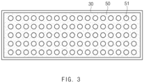
- FIG. 3 which illustrates a state in which a heat transfer layer 50 is stacked on one surface of a separator 30 according to a first embodiment of the present invention
- this embodiment is characterized in that the heat transfer layer 50 stacked on the separator 30 is provided with punched holes 51 having the same size are regularly arranged at a constant interval.
- the punched holes 51 are disposed at a constant interval throughout the heat transfer layer 50 so that ions and charges moving between a negative electrode 20 and a positive electrode 10 uniformly passes therethrough.
- This may be the most basic arrangement structure of the punched holes 50 and be applied together with an arrangement structure to be described later. That is, a plurality of heat transfer layers 50 are provided in an electrode assembly, but the arrangement structure of the punched holes 51 according to the first embodiment may be applied to the most heat transfer layers.
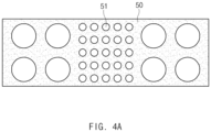
- the heat transfer layer 50 may have punched holes 51, which increase in size at a specific position. For example, when a passing rate of ions and charges at a specific position is more important than heat transfer, the punched hole 51 may more increase in size so that the passing rate of the ions and charges more increases.
- a heat transfer layer 50 according to this embodiment is provided with a punched hole 51 that extends in a longitudinal direction (a left and right direction in the drawings) and/or a width direction (an upward and downward direction in the drawings).
- a punched hole 51 that extends in a longitudinal direction (a left and right direction in the drawings) and/or a width direction (an upward and downward direction in the drawings).
- the structure in which the punched hole 51 extends lengthily may further simplify a coating process in a coating method of the heat transfer layer 50 to be described later.
- FIG. 5 which illustrates an inner configuration of a secondary battery in which a heat transfer layer 50 is stacked according to a fifth embodiment of the present invention
- at least two or more heat transfer layers 50 are disposed in an electrode assembly.
- one heat transfer layer 50 has a thickness greater than that of the other heat transfer layer 50.
- an intermediate position within the electrode assembly may be relatively difficult to dissipate heat rather than the outer side and thus may increase in temperature.
- the heat transfer layer 50 disposed at the intermediate layer to increase in heat transfer efficiency may have a thickness greater than that of the heat transfer layer 50 disposed at the other layer.
- the heat transfer layer 50 having the above-described configuration may be provided in a state applied on a surface of a separator 30 or in the form of a separate plate.
- a heat transfer material may be applied on the surface of the separator 30, and after the heat transfer material is cured, the heat transfer material may be stacked together with the separator 30 within the electrode assembly to form the heat transfer layer 50.
- the heat transfer layer 50 may be previously manufactured in the form of a plate having a size capable of being stacked between a positive electrode 10 and a separator 30 or between a negative electrode 20 and the separator 30.
- the previously manufactured heat transfer layer 50 is stacked together when the positive electrode 10, the separator 30, and the negative electrode 20 are stacked.
- the method for providing the heat transfer layer 50 may be selected according to the number of punched holes 51 or an arranged state of the punched holes 51. For example, a method, in which the heat transfer layer 50 disposed at a specific position is formed in a coating manner, and the heat transfer layer 50 disposed at another position is stacked in the form of a plate, may be applied.
- the electrode assembly according to the present invention is embedded in a pouch 40, and a positive electrode tab 11 and a negative electrode tab 21 are disposed in directions opposite to each other, and an end of each of the tabs protrudes from the pouch 40.
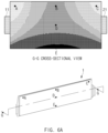
- FIG. 6a is a perspective view of a secondary battery in which the heat transfer layer is not provided, i.e., a perspective view illustrating points A to E listed in Table 1 and a cross-sectional view taken along line G-G (displayed with a relatively dark color at a low temperature)
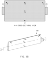
- FIG. 6b is a perspective view of a secondary battery in which a heat transfer layer is additionally stacked, i.e., a perspective view illustrating the points A to E listed in Table 1 and a cross-sectional view taken along line H-H according to the present invention (in FIGS. 6a and 6b , although one secondary battery is illustrated, temperature distribution illustrated in the cross-sectional view is shown when secondary batteries are mounted as a secondary battery module as illustrated in FIG. 1a ).
- Table 1 below shows a temperature difference between when the heat transfer layer is not stacked and when the heat transfer layer is stacked at five points illustrated in FIGS. 6a and 6b .
- the heat transfer layer 50 when the heat transfer layer 50 is provided in an electrode assembly, it may be confirmed that the temperature deviation decreases in an entire region of the secondary battery. That is, when the heat transfer layer 50 is not provided, if heat is generated, cooling is easily performed in the vicinity of a cooling plate, but heat dissipation is difficult at a point that is relatively far from the cooling plate, resulting in a relatively high temperature. Also, here, the heat dispersion is not achieved to cause the heat deviation. However, when the heat transfer layer 50 is added according to the present invention, it may be confirmed that heat generated at a relatively high temperature point is dispersed to a relatively low temperature point, and thus, a heat exposure area to the outside increases to reduce the overall temperature as well as the temperature deviation.
- the structure according to the present invention reduces the temperature deviation and improves the cooling efficiency, the charging/discharging performance and the reliability of the product may be improved.
- the heat transfer layer 50 may be provided with the plurality of punched holes 51 through which the ions pass so as not to interfere with the ion and electron transfer, and the arrangement of the punched holes may vary according to the specifications of the electrode assembly.
- the heat transfer layer 50 is stacked so that the heat transfer layers 50 are stacked on each of both sides with the separator 30 therebetween or stacked to contact only one side surface in one or more separators 30, the above-described configurations may be selected in consideration of the heat dispersion effect and the increase in thickness of the electrode assembly.
- any one heat transfer layer 50 has a thickness greater than that of the other heat transfer layer 50, the heat dispersion effect at the specific location may be more improved.
Landscapes
- Chemical & Material Sciences (AREA)
- Chemical Kinetics & Catalysis (AREA)
- Electrochemistry (AREA)
- General Chemical & Material Sciences (AREA)
- Engineering & Computer Science (AREA)
- Manufacturing & Machinery (AREA)
- Secondary Cells (AREA)
- Cell Separators (AREA)
Description
- The present application claims the benefit of the priority of
Korean Patent Application No. 10-2019-0046622, filed on April 22, 2019 - The present invention relates to an electrode assembly in which negative electrodes, separators, and positive electrodes are repeatedly stacked, and more particularly, to an electrode assembly in which a heat transfer plate that disperses heat is additionally stacked to reduce a temperature deviation therein.
- The demands for high-efficiency secondary batteries are rapidly increasing in the mobile device and electric vehicle fields. Among such the secondary batteries, a lithium secondary battery having high energy density, maintaining a relatively high voltage, and having a low self-discharge rate is commercially widely used, and research and development for improving performance is actively being conducted.
- The secondary battery has a structure in which an electrode assembly and an electrolyte are embedded in a case such as a can or a pouch. The electrode assembly has a structure in which positive electrodes, separators, and negative electrodes are repeatedly stacked. In general, the electrode assembly may be classified into a winding type electrode assembly in which the positive electrodes, the separators, and the negative electrodes, which are in the stacked state, are rolled to be embedded in the case and a stack type (stacked) electrode assembly in which the positive electrodes, the separators, and the negative electrodes, each of which is cut to a predetermined size, are stacked.
- Since the winding type electrode assembly has a spirally wound structure, the winding type electrode assembly is suitable for being mounted on a cylindrical battery, but is disadvantageous in space utilization for a prismatic or pouch type battery. On the other hand, since the stack type electrode assembly is adjusted in size when the electrode and the separator are cut, the prismatic shape fitted with the case is easily obtained, but a manufacturing process is relatively complicated, and the stack type electrode assembly is relatively vulnerable to an external impact.
- As illustrated in
FIG. 1B , which illustrates an internal cross-sectional view of the stack type secondary battery, the number of stacking ofnegative electrodes 20,separators 30, andpositive electrodes 10 is adjusted to easily increase in capacity. - Furthermore, as the secondary battery is charged and discharged, heat is generated in the secondary battery. The heat not only adversely affects the lifespan and performance of the secondary battery but also causes flames or explosion. In addition, recently, as a large capacity secondary battery mounted on a vehicle, an ESS (energy storage system), and the like has been developed, a heat generation amount of the secondary battery increases.
- As illustrated in
FIG. 1A , which illustrates an exploded view and an assembled state of a secondary battery module, in the secondary battery module, a plurality ofsecondary batteries 1 are stacked and then mounted in aframe 60. Here, both electrode tabs are electrically connected to each other through abusbar 80, and acooling plate 70 for suppressing generation of heat in the mountedsecondary batteries 1 is attached to one side surface. In thecooling plate 70, a method in which cooling water is introduced and discharged to be heat-exchanged or a method in which a plurality of cooling fins are formed is typically applied. - In the secondary battery module configured as described above, since the
cooling plate 70 is attached to only one side surface, a thermal deviation inevitably occurs in the electrode assembly within each of the secondary batteries. Since the temperature deviation adversely affects performance and lifespan of each of the secondary batteries within the secondary battery module, it is necessary to solve the temperature deviation.US2017/365829A andUS2016/043370A1 disclose electrode assemblies with a separator provided with a heat transfer layer. - Therefore, a main object of the present invention is to provide an electrode assembly for a secondary battery mounted in the secondary battery module, in which a temperature deviation therein is minimized.
- According to the present invention for achieving the above object, an electrode assembly is defined in the appended set of claims, the electrode assembly in which positive electrodes, separators, and negative electrodes are repeatedly stacked, and a positive electrode tab, through which the positive electrodes are connected to each other, and a negative electrode tab, through which the negative electrodes are connected to each other, are provided, comprises: a heat transfer layer made of a material having thermal conductivity greater than that of the separator and stacked between the positive electrode and the separator or between the negative electrode and the separator to disperse heat generated at a relatively high temperature point to a relatively low temperature point.
- The heat transfer layer may be made of a material containing graphite.
- The heat transfer layer has an area less than that of the separator and be stacked so as not to protrude from the separator. Here, the negative electrode may have an area equal to or greater than that of the positive electrode, and the heat transfer layer may have an area equal to or greater than that of the negative electrode.
- The heat transfer layer is provided with a plurality of punched holes through which ions passes, and the punched holes may be disposed to be regularly arranged in the heat transfer layer.
- In addition, the heat transfer layer may be stacked on each of both sides with the separator therebetween in the one or more separators, and the heat transfer layer may be stacked to contact only one side surface of the separator in the one or more separators.
- Furthermore, at least two or more heat transfer layers may be provided, and one heat transfer layer may have a thickness greater than that of the other heat transfer layer.
- In addition, the separator may be provided in a state in which a heat transfer material is applied on a surface of the separator so that the heat transfer material forms the heat transfer layer in the electrode assembly. In addition, the heat transfer layer may be provided in the form of a plate having a size capable of being stacked between the positive electrode and the separator or between the negative electrode and the separator and is additionally stacked together when the positive electrode, the separator, and the negative electrode are stacked.
- The positive electrode tab and the negative electrode tab may be disposed to protrude in directions opposite to each other.
- In addition, the present invention is additionally provided with a secondary battery in which the electrode assembly having the above technical features is embedded in a pouch.
- The present invention having the configuration as described above may disperse the heat generated at the relatively high temperature point to the relatively low temperature point to reduce the temperature deviation within the electrode assembly. Therefore, since the factors that adversely affect the charging and discharging performance and the lifespan are removed, the reliability of the product may be improved.
- The heat transfer layer is provided with the plurality of punched holes through which the ions pass so as not to interfere with the ion and electron transfer, and the arrangement of the punched holes may vary according to the specifications of the electrode assembly.
- Since the heat transfer layer is stacked so that the heat transfer layers are stacked on each of both sides with the separator therebetween or stacked to contact only one side surface in one or more separators, the above-described configurations may be selected in consideration of the heat dispersion effect and the increase in thickness of the electrode assembly.
- Furthermore, since any one heat transfer layer has a thickness greater than that of the other heat transfer layer, the heat dispersion effect at the specific location may be more improved.
-
-
FIG. 1a is an exploded view of a secondary battery module and a perspective view illustrating an assembled state of the secondary battery module. -
FIG. 1b is a perspective view of a secondary battery mounted inFIG. 1a and a cross-sectional view taken along line F-F. -
FIG. 2 is a cross-sectional view illustrating an inner configuration of the secondary battery according to the present invention. -
FIG. 3 is a plan view illustrating a state in which a heat transfer layer is stacked on one surface of a separator according to a first embodiment of the present invention. -
FIG. 4a is a plan view of a heat transfer layer according to a second embodiment of the present invention. -
FIG. 4b is a plan view of a heat transfer layer according to a third embodiment of the present invention. -
FIG. 4c is a plan view of a heat transfer layer according to a fourth embodiment of the present invention. -
FIG. 5 is a cross-sectional view illustrating an inner configuration of a secondary battery in which a heat transfer layer is stacked according to a fifth embodiment of the present invention. -
FIG. 6a is a perspective view of a secondary battery in which a heat transfer layer is not provided, i.e., a perspective view illustrating points A to E listed in Table 1 and a cross-sectional view taken along line G-G (displayed with a relatively dark color at a low temperature). -
FIG. 6b is a perspective view of a secondary battery in which a heat transfer layer is additionally stacked, i.e., a perspective view illustrating the points A to E listed in Table 1 and a cross-sectional view taken along line H-H according to the present invention. - Hereinafter, preferred embodiments of the present invention will be described in detail with reference to the accompanying drawings in such a manner that the technical idea of the present invention may easily be carried out by a person with ordinary skill in the art to which the invention pertains. The present invention may, however, be embodied in different forms and should not be construed as limited to the embodiments set forth herein.
- In order to clearly illustrate the present invention, parts that are not related to the description are omitted, and the same or similar components are denoted by the same reference numerals throughout the specification.
- Also, terms or words used in this specification and claims should not be restrictively interpreted as ordinary meanings or dictionary-based meanings, but should be interpreted as meanings and concepts conforming to the scope of the present invention on the basis of the principle that an inventor can properly define the concept of a term to describe and explain his or her invention in the best ways.
- The present invention relates to an electrode assembly, in which
positive electrodes 10,separators 30, andnegative electrodes 20 are repeatedly stacked, and apositive electrode tab 11, through which thepositive electrodes 10 are connected to each other, and anegative electrode tab 21, through which thenegative electrodes 20 are connected to each other, are provided so as to be embedded in apouch 40. - An object of the present invention is to prevent performance from being deteriorated due to heat. That is, a main point of the present invention is to improve heat dissipation performance and minimize a thermal deviation when cooling is performed by a cooling means at one side in a state in which a plurality of
secondary batteries 100 are stacked. - Thus, as illustrated in
FIG. 2 , which illustrates an inner configuration of the secondary battery according to the present invention, the electrode assembly according to the present invention comprises aheat transfer layer 50 made of a material having thermal conductivity greater than that of theseparator 30 and stacked between thepositive electrode 10 and theseparator 30 or between thenegative electrode 20 and theseparator 30 to disperse heat generated at a relatively high temperature point to a relatively low temperature point. In the present invention, theheat transfer layer 50 contains a material having high thermal conductivity such as graphite and is provided with a plurality of punchedholes 51 through which electrons and ions pass. - Here, the
heat transfer layer 50 has an area less than that of theseparator 30 so as not to protrude from the electrode assembly. However, theheat transfer layer 50 may have an area equal to or greater than that of thenegative electrode 20 so that an entire heat-exchange area of thenegative electrode 20 and thepositive electrode 10 is maximized in consideration of the fact that thenegative electrode 20 is larger than thepositive electrode 10 to prevent the lithium from being extracted due to overcharging when lithium gets out of thepositive electrode 10 to move to thenegative electrode 20. Theheat transfer layer 50 may be stacked on each of both side surfaces with the separator therebetween or stacked to contact only one side surface of theseparator 30 in one or more separators. - Also, the punched
holes 51 may be disposed to form a constant arrangement in theheat transfer layer 50, i.e., may be variously arranged according to specifications and characteristics of the secondary battery. - Hereinafter, embodiments according to the present invention will be described with reference to the accompanying drawings.
- Referring to
FIG. 3 which illustrates a state in which aheat transfer layer 50 is stacked on one surface of aseparator 30 according to a first embodiment of the present invention, this embodiment is characterized in that theheat transfer layer 50 stacked on theseparator 30 is provided with punchedholes 51 having the same size are regularly arranged at a constant interval. - That is, in this embodiment, the punched
holes 51 are disposed at a constant interval throughout theheat transfer layer 50 so that ions and charges moving between anegative electrode 20 and apositive electrode 10 uniformly passes therethrough. This may be the most basic arrangement structure of the punchedholes 50 and be applied together with an arrangement structure to be described later. That is, a plurality of heat transfer layers 50 are provided in an electrode assembly, but the arrangement structure of the punchedholes 51 according to the first embodiment may be applied to the most heat transfer layers. - As illustrated in
FIG. 4a , which illustrates a plan view of aheat transfer layer 50 according to a second embodiment of the present invention, theheat transfer layer 50 according to this embodiment may have punchedholes 51, which increase in size at a specific position. For example, when a passing rate of ions and charges at a specific position is more important than heat transfer, the punchedhole 51 may more increase in size so that the passing rate of the ions and charges more increases. - As illustrated in
FIGS. 4b and4c , which illustrate a plan view of a heat transfer layer according to third and fourth embodiments of the present invention, aheat transfer layer 50 according to this embodiment is provided with a punchedhole 51 that extends in a longitudinal direction (a left and right direction in the drawings) and/or a width direction (an upward and downward direction in the drawings). As described above, the structure in which the punchedhole 51 extends lengthily may further simplify a coating process in a coating method of theheat transfer layer 50 to be described later. - As illustrated in
FIG. 5 , which illustrates an inner configuration of a secondary battery in which aheat transfer layer 50 is stacked according to a fifth embodiment of the present invention, at least two or more heat transfer layers 50 are disposed in an electrode assembly. Here, oneheat transfer layer 50 has a thickness greater than that of the otherheat transfer layer 50. - That is, an intermediate position within the electrode assembly may be relatively difficult to dissipate heat rather than the outer side and thus may increase in temperature. Here, the
heat transfer layer 50 disposed at the intermediate layer to increase in heat transfer efficiency may have a thickness greater than that of theheat transfer layer 50 disposed at the other layer. - The
heat transfer layer 50 having the above-described configuration may be provided in a state applied on a surface of aseparator 30 or in the form of a separate plate. - That is, a heat transfer material may be applied on the surface of the
separator 30, and after the heat transfer material is cured, the heat transfer material may be stacked together with theseparator 30 within the electrode assembly to form theheat transfer layer 50. - Alternatively, the
heat transfer layer 50 may be previously manufactured in the form of a plate having a size capable of being stacked between apositive electrode 10 and aseparator 30 or between anegative electrode 20 and theseparator 30. The previously manufacturedheat transfer layer 50 is stacked together when thepositive electrode 10, theseparator 30, and thenegative electrode 20 are stacked. - The method for providing the
heat transfer layer 50 may be selected according to the number of punchedholes 51 or an arranged state of the punched holes 51. For example, a method, in which theheat transfer layer 50 disposed at a specific position is formed in a coating manner, and theheat transfer layer 50 disposed at another position is stacked in the form of a plate, may be applied. - The electrode assembly according to the present invention is embedded in a
pouch 40, and apositive electrode tab 11 and anegative electrode tab 21 are disposed in directions opposite to each other, and an end of each of the tabs protrudes from thepouch 40. -
FIG. 6a is a perspective view of a secondary battery in which the heat transfer layer is not provided, i.e., a perspective view illustrating points A to E listed in Table 1 and a cross-sectional view taken along line G-G (displayed with a relatively dark color at a low temperature), andFIG. 6b is a perspective view of a secondary battery in which a heat transfer layer is additionally stacked, i.e., a perspective view illustrating the points A to E listed in Table 1 and a cross-sectional view taken along line H-H according to the present invention (inFIGS. 6a and6b , although one secondary battery is illustrated, temperature distribution illustrated in the cross-sectional view is shown when secondary batteries are mounted as a secondary battery module as illustrated inFIG. 1a ). Table 1 below shows a temperature difference between when the heat transfer layer is not stacked and when the heat transfer layer is stacked at five points illustrated inFIGS. 6a and6b .[Table 1] Point A Point B Point C Point D Point E Maximum temperature deviation Non-stack of heat transfer layer ( FIG. 6a )39.5°C 36.6°C 39.1°C 35.1°C 31.3°C 8.2°C Stack of heat transfer layer ( FIG. 6b )33.3°C 33.0°C 33.2°C 32.8°C 32.5°C 0.8°C ** Experimental conditions - cell capacity: 78 Ah, current load: 100A 10 sec pulse, initial status of charge: 50%, initial temperature: 25°C, coolant temperature: 22°C. - As seen from data in Table 1, when the
heat transfer layer 50 is provided in an electrode assembly, it may be confirmed that the temperature deviation decreases in an entire region of the secondary battery. That is, when theheat transfer layer 50 is not provided, if heat is generated, cooling is easily performed in the vicinity of a cooling plate, but heat dissipation is difficult at a point that is relatively far from the cooling plate, resulting in a relatively high temperature. Also, here, the heat dispersion is not achieved to cause the heat deviation. However, when theheat transfer layer 50 is added according to the present invention, it may be confirmed that heat generated at a relatively high temperature point is dispersed to a relatively low temperature point, and thus, a heat exposure area to the outside increases to reduce the overall temperature as well as the temperature deviation. - Therefore, since the structure according to the present invention reduces the temperature deviation and improves the cooling efficiency, the charging/discharging performance and the reliability of the product may be improved.
- The
heat transfer layer 50 may be provided with the plurality of punchedholes 51 through which the ions pass so as not to interfere with the ion and electron transfer, and the arrangement of the punched holes may vary according to the specifications of the electrode assembly. - Since the
heat transfer layer 50 is stacked so that the heat transfer layers 50 are stacked on each of both sides with theseparator 30 therebetween or stacked to contact only one side surface in one ormore separators 30, the above-described configurations may be selected in consideration of the heat dispersion effect and the increase in thickness of the electrode assembly. - Furthermore, since any one
heat transfer layer 50 has a thickness greater than that of the otherheat transfer layer 50, the heat dispersion effect at the specific location may be more improved. - While the embodiments of the present invention have been described with reference to the specific embodiments, it will be apparent to those skilled in the art that various changes and modifications may be made without departing from the scope of the invention as defined in the following claims.
Claims (11)
- An electrode assembly in which positive electrodes (10), separators (30), and negative electrodes (20) are repeatedly stacked, and a positive electrode tab (11), through which the positive electrodes are connected to each other, and a negative electrode tab (21), through which the negative electrodes are connected to each other, are provided, the electrode assembly comprising:a heat transfer layer (50) made of a material having thermal conductivity greater than that of the separator (30) and stacked between the positive electrode (10) and the separator (30) or between the negative electrode (20) and the separator (30) to disperse heat generated at a relatively high temperature point to a relatively low temperature point,wherein the heat transfer layer (50) is provided with a plurality of punched holes through which ions pass, andthe heat transfer layer (50) has an area less than that of the separator (30) and is stacked so as not to protrude from the separator.
- The electrode assembly of claim 1, wherein the heat transfer layer (50) is made of a material containing graphite.
- The electrode assembly of claim 1, wherein the negative electrode (20) has an area equal to or greater than that of the positive electrode (10), and the heat transfer layer (50) has an area equal to or greater than that of the negative electrode (20).
- The electrode assembly of claim 1, wherein the punched holes (51) are disposed to be regularly arranged in the heat transfer layer (50).
- The electrode assembly of claim 1, wherein the heat transfer layer (50) is stacked on each of both sides with the separator (30) therebetween in the one or more separators.
- The electrode assembly of claim 1, wherein the heat transfer layer (50) is stacked to contact only one side surface of the separator (30) in the one or more separators.
- The electrode assembly of any one of claims 1 to 6, wherein at least two or more heat transfer layers (50) are provided, and one heat transfer layer has a thickness greater than that of the other heat transfer layer.
- The electrode assembly of any one of claims 1 to 6, wherein the separator (30) is provided in a state in which a heat transfer material is applied on a surface of the separator (30) so that the heat transfer material forms the heat transfer layer (50) in the electrode assembly.
- The electrode assembly of any one of claims 1 to 6, wherein the heat transfer layer (50) is provided in the form of a plate having a size capable of being stacked between the positive electrode (10) and the separator (30) or between the negative electrode (20) and the separator (30) and is additionally stacked together when the positive electrode (10), the separator (30), and the negative electrode (20) are stacked.
- The electrode assembly of any one of claims 1 to 6, wherein the positive electrode tab (11) and the negative electrode tab (21) are disposed to protrude in directions opposite to each other.
- A secondary battery in which the electrode assembly of any one of claims 1 to 6 is embedded in a pouch.
Applications Claiming Priority (2)
| Application Number | Priority Date | Filing Date | Title |
|---|---|---|---|
| KR1020190046622A KR102429590B1 (en) | 2019-04-22 | 2019-04-22 | Electrode assembly |
| PCT/KR2020/005219 WO2020218794A1 (en) | 2019-04-22 | 2020-04-20 | Electrode assembly |
Publications (3)
| Publication Number | Publication Date |
|---|---|
| EP3780218A1 EP3780218A1 (en) | 2021-02-17 |
| EP3780218A4 EP3780218A4 (en) | 2021-06-09 |
| EP3780218B1 true EP3780218B1 (en) | 2025-05-28 |
Family
ID=72940736
Family Applications (1)
| Application Number | Title | Priority Date | Filing Date |
|---|---|---|---|
| EP20795261.5A Active EP3780218B1 (en) | 2019-04-22 | 2020-04-20 | Electrode assembly |
Country Status (7)
| Country | Link |
|---|---|
| US (1) | US20210257688A1 (en) |
| EP (1) | EP3780218B1 (en) |
| KR (1) | KR102429590B1 (en) |
| CN (1) | CN112119524A (en) |
| ES (1) | ES3034843T3 (en) |
| HU (1) | HUE071958T2 (en) |
| WO (1) | WO2020218794A1 (en) |
Families Citing this family (2)
| Publication number | Priority date | Publication date | Assignee | Title |
|---|---|---|---|---|
| KR20230119472A (en) * | 2022-02-07 | 2023-08-16 | 주식회사 엘지에너지솔루션 | A lithium secondary battery having a fire suppression structure |
| CN117117183B (en) * | 2023-01-03 | 2024-06-07 | 荣耀终端有限公司 | Negative electrode piece and lithium ion battery |
Family Cites Families (21)
| Publication number | Priority date | Publication date | Assignee | Title |
|---|---|---|---|---|
| TWI346406B (en) * | 2006-02-16 | 2011-08-01 | Lg Chemical Ltd | Lithium secondary battery with enhanced heat-resistance |
| JP4923679B2 (en) * | 2006-03-31 | 2012-04-25 | トヨタ自動車株式会社 | Stacked battery |
| JP2010171030A (en) * | 2008-12-22 | 2010-08-05 | Kaneka Corp | Heat radiating structure |
| KR20100073753A (en) * | 2008-12-23 | 2010-07-01 | 주식회사 효성 | Porous seperator having improved heat-resistance and strength, its manufacturing method and electrochemical cell |
| WO2011021644A1 (en) * | 2009-08-19 | 2011-02-24 | 三菱化学株式会社 | Separator for non-aqueous electrolyte secondary battery and non-aqueous electrolyte secondary battery |
| JP2011165361A (en) * | 2010-02-05 | 2011-08-25 | Sumitomo Heavy Ind Ltd | Storage module and hybrid type working machine |
| JP5891655B2 (en) * | 2010-08-30 | 2016-03-23 | ソニー株式会社 | Nonaqueous electrolyte battery, nonaqueous electrolyte battery manufacturing method, insulating material, insulating material manufacturing method, battery pack, electronic device, electric vehicle, power storage device, and power system |
| JP5834940B2 (en) * | 2012-01-18 | 2015-12-24 | トヨタ自動車株式会社 | Separator for non-aqueous electrolyte secondary battery and non-aqueous electrolyte secondary battery |
| KR101515357B1 (en) * | 2012-02-29 | 2015-04-28 | 제일모직주식회사 | Separator containing mixture coating layer of inorganics and organics, and battery using the separator |
| KR101920714B1 (en) * | 2012-05-16 | 2018-11-21 | 삼성전자주식회사 | Negative electrode for lithium battery and the lithium battery comprising the same |
| JP6186783B2 (en) * | 2013-03-19 | 2017-08-30 | ソニー株式会社 | Separator, battery, battery pack, electronic device, electric vehicle, power storage device, and power system |
| CN105051941B (en) * | 2013-03-19 | 2017-11-21 | 索尼公司 | Barrier film, battery, battery pack, electronic equipment, electric vehicle, power storage devices and power system |
| EP3032607B1 (en) * | 2013-08-07 | 2018-05-09 | Hitachi, Ltd. | Battery module |
| DE102013226743A1 (en) * | 2013-12-19 | 2015-06-25 | Robert Bosch Gmbh | Thermally conductive polymer separator |
| KR101896142B1 (en) * | 2015-01-09 | 2018-09-06 | 주식회사 엘지화학 | Thermal diffusion separator and secondary battery containing the same |
| EP3340365B1 (en) * | 2015-09-21 | 2020-04-22 | LG Chem, Ltd. | Battery module including array of cooling fins having different thicknesses |
| CN105374972B (en) * | 2015-12-14 | 2018-01-19 | 苏州锂盾储能材料技术有限公司 | A kind of lithium ion battery high-temperature-resistant membrane material and preparation method |
| KR20170114171A (en) * | 2016-04-05 | 2017-10-13 | 현대자동차주식회사 | Lithium Secondary Battery And Method of preparing |
| US10439260B2 (en) * | 2016-06-30 | 2019-10-08 | Toyota Jidosha Kabushiki Kaisha | Battery |
| KR102140122B1 (en) * | 2016-08-19 | 2020-07-31 | 주식회사 엘지화학 | Anode comprising multi passivation layers and lithium secondary battery comprising the same |
| CN108258358B (en) * | 2016-12-28 | 2022-11-11 | 松下知识产权经营株式会社 | Battery with a battery cell |
-
2019
- 2019-04-22 KR KR1020190046622A patent/KR102429590B1/en active Active
-
2020
- 2020-04-20 US US17/054,809 patent/US20210257688A1/en not_active Abandoned
- 2020-04-20 HU HUE20795261A patent/HUE071958T2/en unknown
- 2020-04-20 ES ES20795261T patent/ES3034843T3/en active Active
- 2020-04-20 WO PCT/KR2020/005219 patent/WO2020218794A1/en not_active Ceased
- 2020-04-20 CN CN202080002624.0A patent/CN112119524A/en active Pending
- 2020-04-20 EP EP20795261.5A patent/EP3780218B1/en active Active
Also Published As
| Publication number | Publication date |
|---|---|
| KR102429590B1 (en) | 2022-08-05 |
| KR20200123583A (en) | 2020-10-30 |
| HUE071958T2 (en) | 2025-10-28 |
| CN112119524A (en) | 2020-12-22 |
| WO2020218794A1 (en) | 2020-10-29 |
| US20210257688A1 (en) | 2021-08-19 |
| EP3780218A1 (en) | 2021-02-17 |
| ES3034843T3 (en) | 2025-08-25 |
| EP3780218A4 (en) | 2021-06-09 |
Similar Documents
| Publication | Publication Date | Title |
|---|---|---|
| US10826128B2 (en) | Galvanic element having solid-state cell stack | |
| US8685559B2 (en) | Rechargeable battery and battery module | |
| EP3598556A1 (en) | Electrode and electrode assembly | |
| US20130130099A1 (en) | Secondary battery of differential lead structure | |
| US20240079633A1 (en) | Electrode assembly and manufacturing method of the same | |
| EP4597655A1 (en) | Rechargeable battery and battery module | |
| KR102734115B1 (en) | A positive electrode and an electrode assembly comprising the positive electrode | |
| US20120321942A1 (en) | Electrode assembly and secondary battery using the same | |
| EP3780218A1 (en) | Electrode assembly | |
| KR101693289B1 (en) | Secondary battery | |
| US11721839B2 (en) | Electrode assembly with improved connection between electrode tabs | |
| KR20160115557A (en) | Separator and secondary battery using the same | |
| US10586953B2 (en) | High-capacity stacked-electrode metal-ion accumulator capable of delivering high power | |
| US20230268583A1 (en) | Battery | |
| US11322799B2 (en) | Electrode including single-sided electrode with inorganic coating layer attached to slurry on collector and electrode assembly including the same | |
| EP4672470A1 (en) | BATTERY CELL, BATTERY AND ELECTRICAL DEVICE | |
| US12603349B2 (en) | Battery module and battery pack including the same | |
| KR20240133456A (en) | Secondary battery with divided electrode for prevention of internal short circuit | |
| US20250055018A1 (en) | Electrode Assembly and Battery Cell Including the Same | |
| US20260051616A1 (en) | Secondary battery and method for manufacturing the same | |
| EP4708422A1 (en) | Blade battery and battery pack including same | |
| US20250385404A1 (en) | Secondary battery | |
| US20250286165A1 (en) | Housing cover, battery module, and battery pack | |
| JP2025109363A (en) | Power storage device | |
| KR20230151443A (en) | Electrode assembly and battery cell including the same |
Legal Events
| Date | Code | Title | Description |
|---|---|---|---|
| STAA | Information on the status of an ep patent application or granted ep patent |
Free format text: STATUS: THE INTERNATIONAL PUBLICATION HAS BEEN MADE |
|
| PUAI | Public reference made under article 153(3) epc to a published international application that has entered the european phase |
Free format text: ORIGINAL CODE: 0009012 |
|
| STAA | Information on the status of an ep patent application or granted ep patent |
Free format text: STATUS: REQUEST FOR EXAMINATION WAS MADE |
|
| 17P | Request for examination filed |
Effective date: 20201106 |
|
| AK | Designated contracting states |
Kind code of ref document: A1 Designated state(s): AL AT BE BG CH CY CZ DE DK EE ES FI FR GB GR HR HU IE IS IT LI LT LU LV MC MK MT NL NO PL PT RO RS SE SI SK SM TR |
|
| AX | Request for extension of the european patent |
Extension state: BA ME |
|
| A4 | Supplementary search report drawn up and despatched |
Effective date: 20210511 |
|
| RIC1 | Information provided on ipc code assigned before grant |
Ipc: H01M 10/04 20060101AFI20210504BHEP Ipc: H01M 10/654 20140101ALI20210504BHEP Ipc: H01M 10/653 20140101ALI20210504BHEP Ipc: H01M 10/613 20140101ALI20210504BHEP Ipc: H01M 10/0585 20100101ALI20210504BHEP |
|
| RAP1 | Party data changed (applicant data changed or rights of an application transferred) |
Owner name: LG ENERGY SOLUTION LTD. |
|
| RAP3 | Party data changed (applicant data changed or rights of an application transferred) |
Owner name: LG ENERGY SOLUTION, LTD. |
|
| DAV | Request for validation of the european patent (deleted) | ||
| DAX | Request for extension of the european patent (deleted) | ||
| STAA | Information on the status of an ep patent application or granted ep patent |
Free format text: STATUS: EXAMINATION IS IN PROGRESS |
|
| 17Q | First examination report despatched |
Effective date: 20230120 |
|
| GRAP | Despatch of communication of intention to grant a patent |
Free format text: ORIGINAL CODE: EPIDOSNIGR1 |
|
| STAA | Information on the status of an ep patent application or granted ep patent |
Free format text: STATUS: GRANT OF PATENT IS INTENDED |
|
| INTG | Intention to grant announced |
Effective date: 20250212 |
|
| GRAS | Grant fee paid |
Free format text: ORIGINAL CODE: EPIDOSNIGR3 |
|
| GRAA | (expected) grant |
Free format text: ORIGINAL CODE: 0009210 |
|
| STAA | Information on the status of an ep patent application or granted ep patent |
Free format text: STATUS: THE PATENT HAS BEEN GRANTED |
|
| P01 | Opt-out of the competence of the unified patent court (upc) registered |
Free format text: CASE NUMBER: APP_13944/2025 Effective date: 20250321 |
|
| AK | Designated contracting states |
Kind code of ref document: B1 Designated state(s): AL AT BE BG CH CY CZ DE DK EE ES FI FR GB GR HR HU IE IS IT LI LT LU LV MC MK MT NL NO PL PT RO RS SE SI SK SM TR |
|
| REG | Reference to a national code |
Ref country code: GB Ref legal event code: FG4D |
|
| REG | Reference to a national code |
Ref country code: CH Ref legal event code: EP |
|
| REG | Reference to a national code |
Ref country code: DE Ref legal event code: R096 Ref document number: 602020052046 Country of ref document: DE |
|
| REG | Reference to a national code |
Ref country code: IE Ref legal event code: FG4D |
|
| REG | Reference to a national code |
Ref country code: ES Ref legal event code: FG2A Ref document number: 3034843 Country of ref document: ES Kind code of ref document: T3 Effective date: 20250825 |
|
| REG | Reference to a national code |
Ref country code: NL Ref legal event code: MP Effective date: 20250528 |
|
| PG25 | Lapsed in a contracting state [announced via postgrant information from national office to epo] |
Ref country code: FI Free format text: LAPSE BECAUSE OF FAILURE TO SUBMIT A TRANSLATION OF THE DESCRIPTION OR TO PAY THE FEE WITHIN THE PRESCRIBED TIME-LIMIT Effective date: 20250528 |
|
| REG | Reference to a national code |
Ref country code: LT Ref legal event code: MG9D |
|
| PG25 | Lapsed in a contracting state [announced via postgrant information from national office to epo] |
Ref country code: GR Free format text: LAPSE BECAUSE OF FAILURE TO SUBMIT A TRANSLATION OF THE DESCRIPTION OR TO PAY THE FEE WITHIN THE PRESCRIBED TIME-LIMIT Effective date: 20250829 Ref country code: NO Free format text: LAPSE BECAUSE OF FAILURE TO SUBMIT A TRANSLATION OF THE DESCRIPTION OR TO PAY THE FEE WITHIN THE PRESCRIBED TIME-LIMIT Effective date: 20250828 |
|
| PG25 | Lapsed in a contracting state [announced via postgrant information from national office to epo] |
Ref country code: PL Free format text: LAPSE BECAUSE OF FAILURE TO SUBMIT A TRANSLATION OF THE DESCRIPTION OR TO PAY THE FEE WITHIN THE PRESCRIBED TIME-LIMIT Effective date: 20250528 Ref country code: NL Free format text: LAPSE BECAUSE OF FAILURE TO SUBMIT A TRANSLATION OF THE DESCRIPTION OR TO PAY THE FEE WITHIN THE PRESCRIBED TIME-LIMIT Effective date: 20250528 |
|
| PG25 | Lapsed in a contracting state [announced via postgrant information from national office to epo] |
Ref country code: BG Free format text: LAPSE BECAUSE OF FAILURE TO SUBMIT A TRANSLATION OF THE DESCRIPTION OR TO PAY THE FEE WITHIN THE PRESCRIBED TIME-LIMIT Effective date: 20250528 |
|
| PG25 | Lapsed in a contracting state [announced via postgrant information from national office to epo] |
Ref country code: HR Free format text: LAPSE BECAUSE OF FAILURE TO SUBMIT A TRANSLATION OF THE DESCRIPTION OR TO PAY THE FEE WITHIN THE PRESCRIBED TIME-LIMIT Effective date: 20250528 |
|
| PG25 | Lapsed in a contracting state [announced via postgrant information from national office to epo] |
Ref country code: RS Free format text: LAPSE BECAUSE OF FAILURE TO SUBMIT A TRANSLATION OF THE DESCRIPTION OR TO PAY THE FEE WITHIN THE PRESCRIBED TIME-LIMIT Effective date: 20250828 |
|
| PG25 | Lapsed in a contracting state [announced via postgrant information from national office to epo] |
Ref country code: IS Free format text: LAPSE BECAUSE OF FAILURE TO SUBMIT A TRANSLATION OF THE DESCRIPTION OR TO PAY THE FEE WITHIN THE PRESCRIBED TIME-LIMIT Effective date: 20250928 |
|
| REG | Reference to a national code |
Ref country code: HU Ref legal event code: AG4A Ref document number: E071958 Country of ref document: HU |
|
| PG25 | Lapsed in a contracting state [announced via postgrant information from national office to epo] |
Ref country code: LV Free format text: LAPSE BECAUSE OF FAILURE TO SUBMIT A TRANSLATION OF THE DESCRIPTION OR TO PAY THE FEE WITHIN THE PRESCRIBED TIME-LIMIT Effective date: 20250528 |
|
| REG | Reference to a national code |
Ref country code: AT Ref legal event code: MK05 Ref document number: 1799173 Country of ref document: AT Kind code of ref document: T Effective date: 20250528 |
|
| PG25 | Lapsed in a contracting state [announced via postgrant information from national office to epo] |
Ref country code: AT Free format text: LAPSE BECAUSE OF FAILURE TO SUBMIT A TRANSLATION OF THE DESCRIPTION OR TO PAY THE FEE WITHIN THE PRESCRIBED TIME-LIMIT Effective date: 20250528 Ref country code: SM Free format text: LAPSE BECAUSE OF FAILURE TO SUBMIT A TRANSLATION OF THE DESCRIPTION OR TO PAY THE FEE WITHIN THE PRESCRIBED TIME-LIMIT Effective date: 20250528 Ref country code: DK Free format text: LAPSE BECAUSE OF FAILURE TO SUBMIT A TRANSLATION OF THE DESCRIPTION OR TO PAY THE FEE WITHIN THE PRESCRIBED TIME-LIMIT Effective date: 20250528 |
|
| PG25 | Lapsed in a contracting state [announced via postgrant information from national office to epo] |
Ref country code: CZ Free format text: LAPSE BECAUSE OF FAILURE TO SUBMIT A TRANSLATION OF THE DESCRIPTION OR TO PAY THE FEE WITHIN THE PRESCRIBED TIME-LIMIT Effective date: 20250528 |
|
| PG25 | Lapsed in a contracting state [announced via postgrant information from national office to epo] |
Ref country code: EE Free format text: LAPSE BECAUSE OF FAILURE TO SUBMIT A TRANSLATION OF THE DESCRIPTION OR TO PAY THE FEE WITHIN THE PRESCRIBED TIME-LIMIT Effective date: 20250528 |
|
| PG25 | Lapsed in a contracting state [announced via postgrant information from national office to epo] |
Ref country code: SK Free format text: LAPSE BECAUSE OF FAILURE TO SUBMIT A TRANSLATION OF THE DESCRIPTION OR TO PAY THE FEE WITHIN THE PRESCRIBED TIME-LIMIT Effective date: 20250528 |
|
| PG25 | Lapsed in a contracting state [announced via postgrant information from national office to epo] |
Ref country code: IT Free format text: LAPSE BECAUSE OF FAILURE TO SUBMIT A TRANSLATION OF THE DESCRIPTION OR TO PAY THE FEE WITHIN THE PRESCRIBED TIME-LIMIT Effective date: 20250528 |
|
| REG | Reference to a national code |
Ref country code: DE Ref legal event code: R097 Ref document number: 602020052046 Country of ref document: DE |
|
| PLBE | No opposition filed within time limit |
Free format text: ORIGINAL CODE: 0009261 |
|
| STAA | Information on the status of an ep patent application or granted ep patent |
Free format text: STATUS: NO OPPOSITION FILED WITHIN TIME LIMIT |
|
| PGFP | Annual fee paid to national office [announced via postgrant information from national office to epo] |
Ref country code: GB Payment date: 20260324 Year of fee payment: 7 |
|
| REG | Reference to a national code |
Ref country code: CH Ref legal event code: L10 Free format text: ST27 STATUS EVENT CODE: U-0-0-L10-L00 (AS PROVIDED BY THE NATIONAL OFFICE) Effective date: 20260409 |
|
| PGFP | Annual fee paid to national office [announced via postgrant information from national office to epo] |
Ref country code: BE Payment date: 20260323 Year of fee payment: 7 |
|
| PGFP | Annual fee paid to national office [announced via postgrant information from national office to epo] |
Ref country code: FR Payment date: 20260323 Year of fee payment: 7 |
|
| 26N | No opposition filed |
Effective date: 20260303 |