EP3780179A1 - Secondary lithium ion battery - Google Patents
Secondary lithium ion battery Download PDFInfo
- Publication number
- EP3780179A1 EP3780179A1 EP19855763.9A EP19855763A EP3780179A1 EP 3780179 A1 EP3780179 A1 EP 3780179A1 EP 19855763 A EP19855763 A EP 19855763A EP 3780179 A1 EP3780179 A1 EP 3780179A1
- Authority
- EP
- European Patent Office
- Prior art keywords
- positive electrode
- ion secondary
- lithium ion
- secondary battery
- electrolyte
- Prior art date
- Legal status (The legal status is an assumption and is not a legal conclusion. Google has not performed a legal analysis and makes no representation as to the accuracy of the status listed.)
- Granted
Links
Classifications
-
- H—ELECTRICITY
- H01—ELECTRIC ELEMENTS
- H01M—PROCESSES OR MEANS, e.g. BATTERIES, FOR THE DIRECT CONVERSION OF CHEMICAL ENERGY INTO ELECTRICAL ENERGY
- H01M4/00—Electrodes
- H01M4/02—Electrodes composed of, or comprising, active material
- H01M4/13—Electrodes for accumulators with non-aqueous electrolyte, e.g. for lithium-accumulators; Processes of manufacture thereof
- H01M4/131—Electrodes based on mixed oxides or hydroxides, or on mixtures of oxides or hydroxides, e.g. LiCoOx
-
- H—ELECTRICITY
- H01—ELECTRIC ELEMENTS
- H01M—PROCESSES OR MEANS, e.g. BATTERIES, FOR THE DIRECT CONVERSION OF CHEMICAL ENERGY INTO ELECTRICAL ENERGY
- H01M10/00—Secondary cells; Manufacture thereof
- H01M10/05—Accumulators with non-aqueous electrolyte
- H01M10/052—Li-accumulators
- H01M10/0525—Rocking-chair batteries, i.e. batteries with lithium insertion or intercalation in both electrodes; Lithium-ion batteries
-
- H—ELECTRICITY
- H01—ELECTRIC ELEMENTS
- H01M—PROCESSES OR MEANS, e.g. BATTERIES, FOR THE DIRECT CONVERSION OF CHEMICAL ENERGY INTO ELECTRICAL ENERGY
- H01M10/00—Secondary cells; Manufacture thereof
- H01M10/05—Accumulators with non-aqueous electrolyte
- H01M10/056—Accumulators with non-aqueous electrolyte characterised by the materials used as electrolytes, e.g. mixed inorganic/organic electrolytes
- H01M10/0564—Accumulators with non-aqueous electrolyte characterised by the materials used as electrolytes, e.g. mixed inorganic/organic electrolytes the electrolyte being constituted of organic materials only
- H01M10/0566—Liquid materials
- H01M10/0567—Liquid materials characterised by the additives
-
- H—ELECTRICITY
- H01—ELECTRIC ELEMENTS
- H01M—PROCESSES OR MEANS, e.g. BATTERIES, FOR THE DIRECT CONVERSION OF CHEMICAL ENERGY INTO ELECTRICAL ENERGY
- H01M10/00—Secondary cells; Manufacture thereof
- H01M10/05—Accumulators with non-aqueous electrolyte
- H01M10/056—Accumulators with non-aqueous electrolyte characterised by the materials used as electrolytes, e.g. mixed inorganic/organic electrolytes
- H01M10/0564—Accumulators with non-aqueous electrolyte characterised by the materials used as electrolytes, e.g. mixed inorganic/organic electrolytes the electrolyte being constituted of organic materials only
- H01M10/0566—Liquid materials
- H01M10/0568—Liquid materials characterised by the solutes
-
- H—ELECTRICITY
- H01—ELECTRIC ELEMENTS
- H01M—PROCESSES OR MEANS, e.g. BATTERIES, FOR THE DIRECT CONVERSION OF CHEMICAL ENERGY INTO ELECTRICAL ENERGY
- H01M10/00—Secondary cells; Manufacture thereof
- H01M10/42—Methods or arrangements for servicing or maintenance of secondary cells or secondary half-cells
- H01M10/4235—Safety or regulating additives or arrangements in electrodes, separators or electrolyte
-
- H—ELECTRICITY
- H01—ELECTRIC ELEMENTS
- H01M—PROCESSES OR MEANS, e.g. BATTERIES, FOR THE DIRECT CONVERSION OF CHEMICAL ENERGY INTO ELECTRICAL ENERGY
- H01M4/00—Electrodes
- H01M4/02—Electrodes composed of, or comprising, active material
- H01M4/04—Processes of manufacture in general
- H01M4/0402—Methods of deposition of the material
- H01M4/0404—Methods of deposition of the material by coating on electrode collectors
-
- H—ELECTRICITY
- H01—ELECTRIC ELEMENTS
- H01M—PROCESSES OR MEANS, e.g. BATTERIES, FOR THE DIRECT CONVERSION OF CHEMICAL ENERGY INTO ELECTRICAL ENERGY
- H01M4/00—Electrodes
- H01M4/02—Electrodes composed of, or comprising, active material
- H01M4/36—Selection of substances as active materials, active masses, active liquids
- H01M4/362—Composites
- H01M4/364—Composites as mixtures
-
- H—ELECTRICITY
- H01—ELECTRIC ELEMENTS
- H01M—PROCESSES OR MEANS, e.g. BATTERIES, FOR THE DIRECT CONVERSION OF CHEMICAL ENERGY INTO ELECTRICAL ENERGY
- H01M4/00—Electrodes
- H01M4/02—Electrodes composed of, or comprising, active material
- H01M4/36—Selection of substances as active materials, active masses, active liquids
- H01M4/48—Selection of substances as active materials, active masses, active liquids of inorganic oxides or hydroxides
- H01M4/485—Selection of substances as active materials, active masses, active liquids of inorganic oxides or hydroxides of mixed oxides or hydroxides for inserting or intercalating light metals, e.g. LiTi2O4 or LiTi2OxFy
-
- H—ELECTRICITY
- H01—ELECTRIC ELEMENTS
- H01M—PROCESSES OR MEANS, e.g. BATTERIES, FOR THE DIRECT CONVERSION OF CHEMICAL ENERGY INTO ELECTRICAL ENERGY
- H01M4/00—Electrodes
- H01M4/02—Electrodes composed of, or comprising, active material
- H01M4/36—Selection of substances as active materials, active masses, active liquids
- H01M4/48—Selection of substances as active materials, active masses, active liquids of inorganic oxides or hydroxides
- H01M4/50—Selection of substances as active materials, active masses, active liquids of inorganic oxides or hydroxides of manganese
- H01M4/505—Selection of substances as active materials, active masses, active liquids of inorganic oxides or hydroxides of manganese of mixed oxides or hydroxides containing manganese for inserting or intercalating light metals, e.g. LiMn2O4 or LiMn2OxFy
-
- H—ELECTRICITY
- H01—ELECTRIC ELEMENTS
- H01M—PROCESSES OR MEANS, e.g. BATTERIES, FOR THE DIRECT CONVERSION OF CHEMICAL ENERGY INTO ELECTRICAL ENERGY
- H01M4/00—Electrodes
- H01M4/02—Electrodes composed of, or comprising, active material
- H01M4/36—Selection of substances as active materials, active masses, active liquids
- H01M4/48—Selection of substances as active materials, active masses, active liquids of inorganic oxides or hydroxides
- H01M4/52—Selection of substances as active materials, active masses, active liquids of inorganic oxides or hydroxides of nickel, cobalt or iron
- H01M4/525—Selection of substances as active materials, active masses, active liquids of inorganic oxides or hydroxides of nickel, cobalt or iron of mixed oxides or hydroxides containing iron, cobalt or nickel for inserting or intercalating light metals, e.g. LiNiO2, LiCoO2 or LiCoOxFy
-
- H—ELECTRICITY
- H01—ELECTRIC ELEMENTS
- H01M—PROCESSES OR MEANS, e.g. BATTERIES, FOR THE DIRECT CONVERSION OF CHEMICAL ENERGY INTO ELECTRICAL ENERGY
- H01M4/00—Electrodes
- H01M4/02—Electrodes composed of, or comprising, active material
- H01M4/62—Selection of inactive substances as ingredients for active masses, e.g. binders, fillers
- H01M4/621—Binders
- H01M4/622—Binders being polymers
- H01M4/623—Binders being polymers fluorinated polymers
-
- H—ELECTRICITY
- H01—ELECTRIC ELEMENTS
- H01M—PROCESSES OR MEANS, e.g. BATTERIES, FOR THE DIRECT CONVERSION OF CHEMICAL ENERGY INTO ELECTRICAL ENERGY
- H01M4/00—Electrodes
- H01M4/02—Electrodes composed of, or comprising, active material
- H01M4/62—Selection of inactive substances as ingredients for active masses, e.g. binders, fillers
- H01M4/628—Inhibitors, e.g. gassing inhibitors, corrosion inhibitors
-
- H—ELECTRICITY
- H01—ELECTRIC ELEMENTS
- H01M—PROCESSES OR MEANS, e.g. BATTERIES, FOR THE DIRECT CONVERSION OF CHEMICAL ENERGY INTO ELECTRICAL ENERGY
- H01M4/00—Electrodes
- H01M4/02—Electrodes composed of, or comprising, active material
- H01M2004/021—Physical characteristics, e.g. porosity, surface area
-
- H—ELECTRICITY
- H01—ELECTRIC ELEMENTS
- H01M—PROCESSES OR MEANS, e.g. BATTERIES, FOR THE DIRECT CONVERSION OF CHEMICAL ENERGY INTO ELECTRICAL ENERGY
- H01M4/00—Electrodes
- H01M4/02—Electrodes composed of, or comprising, active material
- H01M2004/026—Electrodes composed of, or comprising, active material characterised by the polarity
- H01M2004/027—Negative electrodes
-
- H—ELECTRICITY
- H01—ELECTRIC ELEMENTS
- H01M—PROCESSES OR MEANS, e.g. BATTERIES, FOR THE DIRECT CONVERSION OF CHEMICAL ENERGY INTO ELECTRICAL ENERGY
- H01M4/00—Electrodes
- H01M4/02—Electrodes composed of, or comprising, active material
- H01M2004/026—Electrodes composed of, or comprising, active material characterised by the polarity
- H01M2004/028—Positive electrodes
-
- H—ELECTRICITY
- H01—ELECTRIC ELEMENTS
- H01M—PROCESSES OR MEANS, e.g. BATTERIES, FOR THE DIRECT CONVERSION OF CHEMICAL ENERGY INTO ELECTRICAL ENERGY
- H01M2300/00—Electrolytes
- H01M2300/0017—Non-aqueous electrolytes
- H01M2300/0025—Organic electrolyte
- H01M2300/0028—Organic electrolyte characterised by the solvent
-
- Y—GENERAL TAGGING OF NEW TECHNOLOGICAL DEVELOPMENTS; GENERAL TAGGING OF CROSS-SECTIONAL TECHNOLOGIES SPANNING OVER SEVERAL SECTIONS OF THE IPC; TECHNICAL SUBJECTS COVERED BY FORMER USPC CROSS-REFERENCE ART COLLECTIONS [XRACs] AND DIGESTS
- Y02—TECHNOLOGIES OR APPLICATIONS FOR MITIGATION OR ADAPTATION AGAINST CLIMATE CHANGE
- Y02E—REDUCTION OF GREENHOUSE GAS [GHG] EMISSIONS, RELATED TO ENERGY GENERATION, TRANSMISSION OR DISTRIBUTION
- Y02E60/00—Enabling technologies; Technologies with a potential or indirect contribution to GHG emissions mitigation
- Y02E60/10—Energy storage using batteries
Definitions
- the present application relates to the field of battery technology, in particular to a lithium ion secondary battery.
- Lithium-ion secondary batteries can provide stable voltage and current, have a high-voltage platform, high specific energy, and a wide temperature range, and are environmentally friendly and easy to carry, which have become a mainstream power source of various consumer electronics and electric products.
- Lithium ion secondary batteries with a ternary system positive active material have characteristics of large discharge capacity and high energy density, and thus are a very potential lithium ion secondary battery.
- Such lithium ion secondary batteries have a disadvantage of poor safety performance.
- the inventor has found that incorporation of lithium manganate into a ternary material may improve thermal stability, reduce high-temperature oxygen release, and reduce oxidation in a fully charged state of the ternary material, which may improve safety performance of batteries while keeping the batteries having a higher energy density.
- addition of lithium manganate may negatively affects cycle performance and high-temperature storage performance of batteries.
- the inventor has conducted a lot of research to reduce the negative effects caused by incorporation of lithium manganate, so that batteries have a higher energy density, and also have a higher safety performance, cycle performance and high temperature storage performance.
- a lithium ion secondary battery including a positive electrode plate, a negative electrode plate, a separator and an electrolyte
- the positive electrode plate includes a positive electrode current collector and a positive electrode film provided on at least one surface of the positive electrode current collector, and the positive electrode film includes a first positive electrode active material represented by chemical formula (1) and a second positive electrode active material represented by chemical formula (2), Li 1+x Ni a Co b Me 1-a-b O 2-y A y chemical formula (1) Li 1+z Mn c N 2-c O 4-d B d chemical formula (2)
- Me includes one or more of Mn, Fe, Cr, Ti, Zn, V, Al, Zr and Ce
- N includes one or more of Ni, Fe, Cr, Ti, Zn, V, Al, Mg, Zr and Ce
- the positive electrode plate has a resistivity r of 3500 ⁇ m or less
- the electrolyte includes a fluorine-containing lithium salt type additive.
- the synergistic effect between the first positive electrode active material and the second positive electrode active material enables positive electrode active materials to have high gram capacity and high thermal stability both, which further significantly improves the problems of high-temperature oxygen release and strong oxidizing problem in the fully charged state of the first positive electrode active material, so that the batteries exhibit greatly improved safety performance while having a higher energy density.
- the synergistic effect may also reduce precipitation of metal ions such as manganese ions from positive active materials.
- a fluorine-containing lithium salt type additive is added to the electrolyte to form a stable LiF passivation layer on the surface of positive electrode active materials, which can further improve structural stability and corrosion resistance of positive electrode active materials, and reduce precipitation of metal ions such as manganese ions.
- the protective effect of the LiF passivation layer also reduces the side reaction between positive electrode active materials and an electrolyte. As a result, safety performance of the lithium ion secondary battery is further improved, and high-temperature storage performance and cycle performance of the battery are also significantly improved.
- the positive electrode plate has a resistivity of 3500 ⁇ ⁇ m or less, which can effectively control increase in battery internal impedance caused by the second positive electrode active material and the LiF passivation layer, and further improve high-temperature storage performance and cycle performance of the battery.
- the lithium ion secondary battery according to embodiments of the present application can have high specific capacity and energy density, while keeping high safety performance, high temperature storage performance and cycle performance.
- ranges from any lower limit may be combined with any upper limit to recite a range not explicitly recited
- ranges from any lower limit may be combined with any other lower limit to recite a range not explicitly recited
- ranges from any upper limit may be combined with any other upper limit to recite a range not explicitly recited.
- within a range includes every point or individual value between its end points even though not explicitly recited. Thus, every point or individual value may serve as its own lower or upper limit combined with any other point or individual value or any other lower or upper limit, to recite a range not explicitly recited.
- a lithium ion secondary battery comprising a positive electrode plate, a negative electrode plate, a separator and electrolyte.
- the positive electrode plate comprises a positive electrode current collector and a positive electrode film disposed on at least one surface of the positive electrode current collector.
- the positive electrode film comprises a positive electrode active material, which can reversibly deintercalate/intercalate lithium ions during working.
- the positive current collector is adapted to collect and conduct current.
- the positive electrode current collector comprises two opposite surfaces in its thickness direction, and the positive electrode film is disposed on either or both of the two opposite surfaces of the positive electrode current collector.
- the positive electrode active material comprises a first positive electrode active material and a second positive electrode active material.
- the first positive electrode active material is a compound represented by chemical formula (1), Li 1+x Ni a Co b Me 1-a-b O 2-y A y chemical formula (1) in which chemical formula (1), -0.1 ⁇ x ⁇ 0.2, 0 ⁇ a ⁇ 1, 0 ⁇ b ⁇ 1, 0 ⁇ a+b ⁇ 1, 0 ⁇ y ⁇ 0.2, Me comprises one or more of Mn, Fe, Cr, Ti, Zn, V, Al, Zr and Ce, and A comprises one or more of S, N, F, Cl, Br and I.
- the second positive electrode active material is a compound represented by chemical formula (2) Li 1+z Mn c N 2-c O 4-d B d chemical formula (2) in which chemical formula (2), -0.1 ⁇ z ⁇ 0.2, 0 ⁇ c ⁇ 2, 0 ⁇ d ⁇ 1, N comprises one or more of Ni, Fe, Cr, Ti, Zn, V, Al, Mg, Zr and Ce, and B comprises one or more of S, N, F, Cl, Br and I.
- the positive electrode plate has a resistivity r of 3500 ⁇ m or less; and the electrolyte comprises a fluorine-containing lithium salt type additive.
- the synergistic effect between the first positive electrode active material and the second positive electrode active material enables the positive electrode active material to have high gram capacity and high thermal stability both, which further significantly improves problems of high-temperature oxygen release and strong oxidizing problem in the fully charged state of the first positive electrode active material, so that the batteries exhibit greatly improved safety performance while having a higher energy density.
- the synergistic effect may also reduce precipitation of metal ions such as manganese ions from the positive active material.
- a fluorine-containing lithium salt type additive is added to the electrolyte to form a stable LiF passivation layer on the surface of the positive electrode active material, and to better protect the positive electrode active material.
- the protective effect of the LiF passivation layer can further improve structural stability and corrosion resistance of the positive electrode active material, and reduce precipitation of metal ions such as manganese ions from the positive electrode active material; and at the same time, also reduces the side reaction between the positive electrode active material and the electrolyte.
- safety performance of the lithium ion secondary battery is further improved, and high-temperature storage performance and cycle performance of the battery are also significantly improved.
- the positive electrode plate has a resistivity of 3500 ⁇ m or less, which can effectively control increase in battery internal impedance caused by the second positive electrode active material and the LiF passivation layer, and further improve high-temperature storage performance and cycle performance of the battery.
- the lithium ion secondary battery according to embodiments of the present application can have high specific capacity and energy density, while keeping high safety performance, high temperature storage performance and cycle performance at the same time.
- the lithium ion secondary battery according to embodiments of the present application may have higher high-temperature storage performance and high-temperature cycle performance, for example, from 40°C to 80°C.
- the lithium ion secondary battery according to embodiments of the present application may have a relatively high comprehensive electrochemical performance in a wide temperature range, for example, from -30°C to 80°C.
- the positive electrode plate has a resistivity of 2500 ⁇ m or less; more preferably, of 1200 ⁇ m or less.
- the lithium ion secondary battery according to embodiments of the present application also comprises a second positive electrode active material, which enable lithium ion secondary battery comprising the first positive electrode active material to have higher safety performance, high-temperature storage performance and cycle performance.
- the weight ratio ⁇ of the first positive electrode active material to the second positive electrode active material in a positive electrode active material is preferably 2:8-99.5:0.5.
- the above weight ratio of the first positive electrode active material to the second positive electrode active material is suitable, which is beneficial to improving safety performance, high-temperature storage performance and cycle performance of the lithium ion secondary battery.
- the positive electrode film comprises manganese element preferably in a weight v in the range of 1.1 ⁇ 10 -3 g/cm 2 ⁇ 9.1 ⁇ 10 -3 g/cm 2 per unit area; more preferably the positive electrode film comprises manganese element preferably in a weight v in the range of 1.1 ⁇ 10 -3 g/cm 2 ⁇ 8.2 ⁇ 10 -3 g/cm 2 per unit area.
- the above weight content of manganese in a positive electrode film is suitable, which is beneficial to improve safety performance, high temperature storage performance and cycle performance of the lithium ion secondary battery.
- the positive electrode film may further comprises a conductive agent and a binder.
- a conductive agent and a binder There is no specific limit in the present application to the type of the conductive agent and binder in the positive electrode film, which can be selected according to actual demands.
- the conductive agent may be one or more of graphite, superconducting carbon, acetylene black, carbon black, Ketjen black, carbon dots, carbon nanotubes, graphene, and carbon nanofibers; and the binder may be one or more of styrene butadiene rubber (SBR), water-based acrylic resin, carboxymethyl cellulose (CMC), polyvinylidene fluoride (PVDF), polytetrafluoroethylene (PTFE), polyvinyl butyral (PVB), ethylene-vinyl acetate copolymer (EVA) and polyvinyl alcohol (PVA).
- SBR styrene butadiene rubber
- CMC carboxymethyl cellulose
- PVDF polyvinylidene fluoride
- PTFE polytetrafluoroethylene
- PVB polyvinyl butyral
- EVA ethylene-vinyl acetate copolymer
- PVA polyvinyl alcohol
- the weight ratio of the conductive agent to the positive electrode active material is greater than or equal to 1.5:95.5, and the weight percentage of the binder in the positive electrode active material layer is less than or equal to 2 wt%.
- the content of conductive agent and binder in the positive electrode film is within above predetermined range, which is beneficial to fully cover the positive electrode active material by the conductive agent, so as to form a uniform and rapid electron transport network, thereby improving rate performance and cycle performance of the lithium ion secondary battery.
- the positive electrode current collector can be a metal foil or a porous metal plate, for example, a foil or a porous plate made of metals such as aluminum, copper, nickel, titanium, or silver or their alloys, such as aluminum foil.
- the positive electrode plate can be prepared by coating.
- the positive electrode plate is prepared by first mixing a positive electrode active material, a binder, a conductive agent and an organic solvent in a predetermined ratio in which the solvent can be N-methylpyrrolidone (NMP), and stirring the mixture uniformly, thereby obtaining a positive electrode slurry; then coating the positive slurry on a positive electrode current collector, followed by the processes of drying and rolling.
- the positive electrode active material comprises the aforementioned first positive electrode active material and the aforementioned second positive electrode active material.
- the first positive electrode active material and the second positive electrode active material are added at the same time, in which a lower electrode plate resistivity is obtained by adjusting the stirring process.
- the first positive electrode active material, the second positive electrode active material, the conductive agent, the binder, and the solvent are added to a vacuum mixer under stirring to obtain a homogenous mixture.
- the stirring rate can be 800r/min ⁇ 1600r/min, preferably 1000r/min ⁇ 1200r/min.
- the stirring time can be 60min ⁇ 180min, preferably 90min ⁇ 150min. Such a process can achieve a lower electrode plate resistivity and improve uniformity of electron transmission network.
- the first positive active material and the second positive active material may be added in order.
- the process is carried out by first adding the first positive electrode active material, the binder, the conductive agent, and the organic solvent, for example, in a vacuum mixer, under stirring to obtain a stable pre-slurry in which the stirring rate is 800r/min ⁇ 1600r/min, such as 1000r/min ⁇ 1200r/min, and the stirring time is 60min ⁇ 180min, such as 90min ⁇ 150min; then adding a predetermined amount of the second positive electrode active material to the pre-slurry in a vacuum mixer under stirring to form a positive electrode slurry in which the stirring rate is 800r/min ⁇ 1600r/min, such as 1000r/min ⁇ 1200r/min, and the stirring time is 60min ⁇ 180min, such as 90min ⁇ 150min.
- Such a process is more conducive to reducing resistivity of positive electrode plate and improving uniformity of electron transport network.
- the negative electrode plate may comprise a negative electrode current collector and a negative electrode film provided on at least one surface of the negative electrode current collector.
- the negative electrode current collector comprises two opposite surfaces in its thickness direction, and the negative electrode film is disposed on either or both of the two opposite surfaces of the negative electrode current collector.
- the negative electrode film comprises a negative electrode active material, which can reversibly deintercalate/intercalate lithium ions during working.
- the negative current collector is adapted to collect and conduct current.
- the negative electrode active material may be one or more of natural graphite, artificial graphite, mesophase micro-carbon bead (MCMB), hard carbon, soft carbon, silicon, silicon-carbon composite, SiO, Li-Sn alloy, Li-Sn-O alloy , Sn, SnO, SnO 2 , lithium titanate Li 4 Ti 5 O 12 with a spinel structure, Li-Al alloy and metal lithium.
- MCMB mesophase micro-carbon bead
- the negative electrode film may further include a conductive agent and a binder.
- a conductive agent may be one or more of graphite, superconducting carbon, acetylene black, carbon black, Ketjen black, carbon dots, carbon nanotubes, graphene, and carbon nanofibers
- the binder may be one or more of styrene butadiene rubber (SBR), polyvinylidene fluoride (PVDF), polytetrafluoroethylene (PTFE), polyvinyl butyral (PVB), water-based acrylic resin, and carboxymethyl cellulose (CMC).
- SBR styrene butadiene rubber
- PVDF polyvinylidene fluoride
- PTFE polytetrafluoroethylene
- PVB polyvinyl butyral
- water-based acrylic resin and carboxymethyl cellulose (CMC).
- the negative electrode film may optionally comprise a thickener, such as carboxymethyl cellulose (CMC).
- CMC carboxymethyl cellulose
- the negative electrode current collector can be a metal foil or a porous metal plate, for example, a foil or a porous plate made of metals such as copper, nickel, titanium, or iron or their alloys, such as copper foil.
- the negative electrode plate can be prepared according to a conventional process in the art.
- the negative electrode plate is prepared by dispersing the negative electrode active material and optionally the conductive agent, the binder, and the thickener in a solvent in which the solvent can be N-methylpyrrolidone (NMP) or deionized water, to form a homogenous negative slurry; then coating the negative slurry on a negative electrode current collector, followed by the processes of drying and cold-pressing.
- NMP N-methylpyrrolidone
- the negative electrode plate may be a metal lithium plate.
- the separator of the lithium ion secondary battery which can be any known porous structural separator with electrochemical and chemical stability.
- the separator is a mono-layer or multi-layer film selected from one or more of glass fiber, non-woven fabric, polyethylene (PE), polypropylene (PP), and polyvinylidene fluoride (PVDF).
- the electrolyte may comprise an organic solvent, an electrolyte lithium salt, and additives.
- organic solvents and electrolyte lithium salts There is no specific limit in the present application to the types of organic solvents and electrolyte lithium salts, which can be selected according to actual needs.
- the organic solvent may be one or more of ethylene carbonate (EC), propylene carbonate (PC), ethyl methyl carbonate (EMC), diethyl carbonate (DEC), dimethyl carbonate (DMC), dipropyl carbonate (DPC), methyl propyl carbonate (MPC), ethyl propyl carbonate (EPC), methyl formate (MF), methyl acetate (MA), ethyl acetate (EA), propyl acetate (PA), methyl propionate (MP), ethyl propionate (EP), propyl propionate (PP), methyl butyrate (MB) and ethyl butyrate (EB), such as one or more of ethylene carbonate (EC), ethyl methyl carbonate (EMC), diethyl carbonate (DEC), dimethyl carbonate (DMC), methyl formate (MF), methyl acetate (MA), ethyl acetate (EA) , propyl methyl formate
- the electrolyte lithium salt may be one or more of LiPF 6 (lithium hexafluorophosphate), LiBF 4 (lithium tetrafluoroborate), LiClO 4 (lithium perchlorate), LiAsF 6 (lithium hexafluoroarsenate), LiFSI (lithium bisfluorosulfonimide), LiTFSI (lithium bistrifluoromethanesulfonimide), LiTFS (lithium trifluoromethanesulfonate), LiDFOB (lithium difluorooxalate borate), LiBOB (lithium dioxalate borate), LiPO 2 F 2 (lithium difluorophosphate), LiDFOP (lithium fluorooxalate phosphate) and LiTFOP (lithium tetrafluorooxalate phosphate), such as one or more LiPF 6 (lithium hexafluorophosphate), LiBF 4 (lithium tetrafluoroborate), LiC
- the additives may comprise fluorine-containing lithium salt type additives.
- the fluorine-containing lithium salt type additive is one or more of a compound represented by chemical formula (3) and a compound represented by chemical formula (4).
- R is one or more of F, Cl, Br, and I, and R comprises F
- Using one or more of the compound represented by the chemical formula (3) and the compound represented by the chemical formula (4) as fluorine-containing lithium salt type additives can form a stable LiF passivation layer on the surface of the positive electrode active material.
- the LiF passivation layer can alleviate structural degradation of the positive electrode active material caused by John-Teller effect, and reduce corrosion of the positive electrode by acidic substances in the electrolyte, so that the structure of the positive electrode active material is more stable, and precipitation of metal ions such as manganese is significantly reduced.
- the LiF passivation layer can also reduce side reaction between the positive electrode active material and the electrolyte. As a result, high-temperature storage performance and cycle performance of the lithium ion secondary battery are further improved.
- the fluorine-containing lithium salt type additive is one or more of LiPO 2 F 2 (lithium difluorophosphate), LiDFOP (lithium difluorooxalate phosphate), LiBF 4 , (lithium tetrafluoroborate) and LiDFOB (lithium difluorooxalate borate).
- LiPO 2 F 2 lithium difluorophosphate
- LiDFOP lithium difluorooxalate phosphate
- LiBF 4 Li tetrafluoroborate
- LiDFOB lithium difluorooxalate borate
- the fluorine-containing lithium salt type additive is present in the electrolyte in a weight percentage u of 0.005wt% ⁇ 3wt%, preferably 0.1wt% ⁇ 2wt%.
- the positive electrode plate and the electrolyte satisfy the following formula (11) 0.005 ⁇ u 100 v ⁇ 27.5 in which v is the weight of manganese element contained in the positive electrode film per unit area, in g/cm 2 ; and u is the weight percentage of the fluorine-containing lithium salt type additive in the electrolyte, in wt %.
- Making the positive electrode plate and the electrolyte satisfy the formula (11) can further improve high temperature storage performance and cycle performance of the lithium ion secondary battery.
- the positive electrode plate and the electrolyte satisfy the following formula (12) 0.01 ⁇ u 100 v ⁇ 20.0
- the compound represented by the above chemical formula (3) and the compound represented by the chemical formula (4) can be used as both fluorine-containing lithium salt type additives and electrolyte lithium salts, as long as the fluorine-containing lithium salt type additive is guaranteed to meet the preset amount, i.e. the amount is sufficient to ensure effective passivation between the positive electrode plate and the electrolyte.
- a negative electrode film-forming enhancer is further contained in the electrolyte.
- the negative electrode film-forming enhancer is one or more of cyclic carbonates with unsaturated bonds in side chains, fluorine-containing cyclic carbonates and cyclic sulfonates.
- the negative electrode film-forming enhancer can improve rigidity of the negative electrode interface film and prevent damage to the negative electrode interface film caused by addition of fluorine-containing lithium salt type additives, thereby better protecting the negative electrode.
- Adding a negative electrode film-forming enhancer to the electrolyte may enable the lithium ion secondary battery to have higher high-temperature storage performance and cycle performance; which can further inhibit gas production and improve safety performance of the battery at the same time.
- the negative electrode film-forming enhancer is one or more of Vinyl Ethylene Carbonate (VEC), Methylene Methanedisulfonate (MMDS), Difluoro Ethylene Carbonate (DFEC), Trifluoromethyl Ethylene Carbonate (TFPC) and 1-propene-1,3-sultone (PST).
- VEC Vinyl Ethylene Carbonate
- MMDS Methylene Methanedisulfonate
- DFEC Difluoro Ethylene Carbonate
- TFPC Trifluoromethyl Ethylene Carbonate
- PST 1-propene-1,3-sultone
- the negative electrode film-forming enhancer can further improve high-temperature storage performance and cycle performance of the lithium ion secondary battery.
- the weight percentage of the negative electrode film-forming enhancer in the electrolyte is 0.005wt%-6wt%. Further preferably, the weight percentage of the negative electrode film-forming enhancer in the electrolyte is 0.01 wt% to 5 wt%. More preferably, the weight percentage of the negative electrode film-forming enhancer in the electrolyte is 0.1 wt% to 2 wt%.
- the electrolyte may optionally contain other additives, such as one or more of ethylene carbonate (VC), fluoroethylene carbonate (FEC), ethylene sulfate (DTD), succinonitrile (SN), adiponitrile (ADN), cyclic quaternary ammonium salt of sulfonate, tris(trimethylsilyl) phosphate (TMSP) and tris(trimethylsilyl) borate (TMSB).
- VC ethylene carbonate
- FEC fluoroethylene carbonate
- DTD ethylene sulfate
- SN succinonitrile
- ADN adiponitrile
- TMSP tris(trimethylsilyl) phosphate
- TMSB tris(trimethylsilyl) borate
- the positive electrode plate and the electrolyte satisfy the following formula (21), -1.2 ⁇ ln r - s 1 ⁇ 2 formula (21) in which, r is the resistivity of the positive electrode plate in ⁇ m; and s 1 is the ionic conductivity of the electrolyte at 25° C in mS/cm.
- Making the positive electrode plate and the electrolyte satisfy the formula (21) can further improve high temperature storage performance and cycle performance of the lithium ion secondary battery.
- the positive electrode plate and the electrolyte satisfy the following formula (22), -0.5 ⁇ ln r - s 1 ⁇ 1.5 formula (22)
- the electrolyte has an ionic conductivity of preferably 6.0 mS/cm or more, more preferably 7.6 mS/cm or more, and more preferably 8.0 mS/cm or more.
- the organic solvent with a viscosity of less than or equal to 0.7 mPa•s is present in the electrolyte in a weight percentage of 40 wt% to 80 wt%, which enables the electrolyte to have both a lower viscosity and a higher dielectric constant.
- the electrolyte may be prepared according to conventional processes in the art.
- the organic solvent, electrolyte lithium salt and additives can be mixed uniformly to obtain an electrolyte.
- the electrolyte may be obtained by adding the electrolyte lithium salt and additives to the organic solvent and mixing them uniformly.
- the electrolyte may be obtained by adding the electrolyte lithium salt to the organic solvent first, and then adding the additives to the organic solvent.
- the positive electrode plate, the separator and the negative electrode plate are stacked in order, so that the separator was sandwiched in between the positive electrode plate and the negative electrode plate, and then the stack is used a battery core or may be wound into a battery core; the battery core is placed in a packaging shell in which the electrolyte is injected and then sealed to obtain a lithium ion secondary battery.
- a positive electrode plate was prepared as follows: LiNi 0.8 Co 0.1 Mn 0.1 O 2 as a first positive active material, LiMn 2 O 4 as a second positive active material were mixed homogenously at a weight ratio ⁇ of 65:35, and the combined positive electrode active material, conductive carbon black and PVDF as a binder were dispersed at a weight ratio of 96: 2: 2 in NMP and mixed homogenously for 60 minutes, to form a mixture slurry. And then the positive electrode slurry was coated on the surface of a positive current collector in the form of aluminum foil, followed by drying, cold-pressing, slitting and cutting, thereby obtaining the positive electrode plate.
- a negative electrode plate was prepared as follows: graphite as a negative electrode active material, conductive carbon black SP, CMC as a thickener and SBR as a binder were dispersed at a weight ratio of 96: 1: 1: 2 in deionized water and mixed homogeneously to obtain a negative slurry. And then the negative slurry was coated on the surface of a negative current collector in the form of copper foil, followed by drying, cold-pressing, slitting and cutting, thereby obtaining the negative electrode plate.
- Ethylene carbonate (EC), ethyl methyl carbonate (EMC), and diethyl carbonate (DEC) were mixed to obtain an organic solvent.
- 1 mol/L of LiPF 6 was dissolved in the above resulting organic solvent to which 0.1 wt% of LiPO 2 F 2 as a fluorine-containing lithium salt type additive based on the total weight of the electrolyte was added and mixed uniformly, thereby obtaining an electrolyte.
- PP/PE/PP was used as a separator, and the positive electrode plate, the separator and the negative electrode plate were stacked in order in which the separator was sandwiched in between the positive electrode plate and the negative electrode plate for separation, and then the stack was wound into a battery core.
- the battery core was put into a soft case followed by sealing at the top side and infusing with the electrolyte, thereby forming a soft case battery.
- Example 2 was prepared in the same procedure as Example 1 except that in the preparation of positive electrode plate, LiNi 0.8 Co 0.1 Mn 0.1 O 2 as a first positive active material, conductive carbon black, PVDF as a binder and NMP as a solvent were mixed and beaten, thereby forming a stable pre-slurry; to the pre-slurry, LiMn 2 O 4 as a second positive active material was added to form a mixture and the mixture was stirred and mixed uniformly in which the stirring time is 60 minutes, thereby obtaining a positive electrode slurry; the positive electrode slurry was coated on the surface of a positive current collector in the form of aluminum foil, followed by drying, cold-pressing, slitting and cutting, thereby obtaining the positive electrode plate wherein the weight ratio ⁇ of LiNi 0.8 Co 0.1 Mn 0.1 O 2 as a first positive active material and LiMn 2 O 4 as a second positive active material was 65:35 and the weight ratio of the total positive electrode active materials, the conductive carbon black, and PVDF
- Example 2 was prepared with the same procedure as in Example 2 except that in the preparation of the positive electrode plate, the stirring time for mixing the mixture was 100 minutes.
- Example 4 was prepared with the same procedure as in example 2 except that in the preparation of the positive electrode plate, the stirring time for mixing the mixture was 150 minutes.
- Examples 5-35 were prepared with the same procedure as in example 2 except that the relevant parameters of the preparation steps for the positive electrode plate and of the preparation steps for the electrolyte were adjusted. Detailed parameters were summarized in table 1.
- Comparative Example 1 was prepared with the same procedure as in example 1 except that in the preparation of positive electrode plate, LiNi 0.8 Co 0.1 Mn 0.1 O 2 as a positive active material, conductive carbon black, PVDF as a binder and NMP as a solvent were mixed uniformly, thereby forming a positive electrode slurry; the positive electrode slurry was coated on the surface of a positive current collector in the form of aluminum foil, followed by drying, cold-pressing, slitting and cutting, thereby obtaining the positive electrode plate wherein the weight ratio of the positive active material of LiNi 0.8 Co 0.1 Mn 0.1 O 2 , the conductive carbon black, and PVDF was 96: 2: 2.
- Comparative Example 2 was prepared with the same procedure as in example 1 except that in the preparation of positive electrode plate, LiMn 2 O 4 as a positive active material, conductive carbon black, PVDF as a binder and NMP as a solvent were mixed uniformly, thereby forming a positive electrode slurry; the positive electrode slurry was coated on the surface of a positive current collector in the form of aluminum foil, followed by drying, cold-pressing, slitting and cutting, thereby obtaining the positive electrode plate wherein the positive active material LiMn 2 O 4 , the conductive carbon black, and PVDF were present at a weight ratio of 96: 2: 2.
- Comparative Example 3 was prepared with the same procedure as in example 1 except that in the preparation of the positive electrode plate, the stirring time for mixing the mixture was 50 minutes.
- Comparative examples 4-5 were prepared with the same procedure as in example 2 except that the relevant parameters of the preparation steps for the electrolyte were adjusted. Detailed parameters were summarized in table 1.
- Resistance R of a positive electrode plate was measured with Hioki BT3562 internal resistance tester, comprising the steps of: cutting a test sample with a size of 10cm ⁇ 10cm from a positive electrode plate; clamping the upper and lower sides of the test sample on the two conductive terminals of the internal resistance tester, applying a certain pressure for fixture, and testing the resistance R of the positive electrode plate wherein the diameter of the conductive terminal was 14mm, the applied pressure was 15MPa ⁇ 27MPa, and the sampling time range is 5s ⁇ 17s.
- the fresh lithium ion secondary batteries were left for 5 minutes, charged at a constant current of 1C to 4.2V, and then charged at a constant voltage until the current was less than or equal to 0.05C. After that, the charged batteries were left for 5 minutes and then discharged at a constant current of 1C to 3.0V. This is a charge and discharge cycle. The resulting discharge capacity was recorded as the discharge capacity for the first cycle.
- These lithium ion secondary batteries were subjected to a 400-cycle charge-discharge test following the procedure described above, and the discharge capacity for each cycle was recorded.
- Capacity retention (%) of lithium ion secondary battery after 400 cycles of 1C/1C at 45°C the discharge capacity after the 400th cycle / the discharge capacity after the first cycle ⁇ 100%.
- the fresh lithium ion secondary batteries were left for 5 minutes, charged at a constant current of 1C to 4.2V, and then charged at a constant voltage until the current was less than or equal to 0.05C. After that, the charged batteries were left for 5 minutes and then discharged at a constant current of 1C to 3.0V. The resulting discharge capacity was recorded as the initial discharge capacity.
- the fresh lithium ion secondary batteries were left for 5 minutes, charged at a constant current of 1C to 4.2V, and then charged at a constant voltage until the current was less than or equal to 0.05C. After that, the charged batteries were left for 5 minutes and then the lithium ion secondary batteries in the fully charged state were stored in an oven at 60 ° C for 60 days.
- the lithium ion secondary batteries were removed from the oven and then naturally cooled down to 25 ° C.
- the cooled lithium ion secondary batteries were charged at a constant current of 1C to 4.2V, and then charged at a constant voltage until the current was less than or equal to 0.05C.
- the charged batteries were left for 5 minutes and then discharged at a constant current of 1C to 3.0V.
- the resulting discharge capacity was recorded as the discharge capacity after high-temperature storage for 60 days.
- Capacity retention (%) of lithium ion secondary battery after high temperature storage for 60 days the discharge capacity after high temperature storage for 60 days / the initial discharge capacity ⁇ 100%.
- the fresh lithium ion secondary batteries were left for 5 minutes, charged at a constant current of 1C to 4.2V, and then charged at a constant voltage until the current was less than or equal to 0.05C. After that, the lithium ion secondary battery was pierced through with a 5mm diameter nail at a speed of 10mm/s and the maximum surface temperature and phenomenon of the lithium ion secondary battery were monitored.
- Comparative analysis of Examples 1 to 7 and Comparative Example 3 showed that the lithium ion secondary batteries in which the positive electrode plate comprised the first positive electrode active material and the second positive electrode active material, and the electrolyte comprised the fluorine-containing lithium salt type additive exhibited significantly improved capacity retention after 400 cycles of 1C/1C at 45°C and capacity retention after 60°C storage for 60 days when the resistivity of the positive electrode plate is less than or equal to 3500 ⁇ •m and that the lithium ion secondary batteries had high safety performance, high temperature storage performance and cycle performance.
- Comparative analysis of Examples 2, 5-7 and 16-20 and Comparative Examples 4-5 showed that the lithium ion secondary batteries in which the positive electrode plate comprised the first positive electrode active material and the second positive electrode active material, and the resistivity of the positive electrode plate is less than or equal to 3500 ⁇ •m exhibited significantly improved capacity retention after 400 cycles of 1C/1C at 45°C and capacity retention after 60°C storage for 60 days when the electrolyte comprised the fluorine-containing lithium salt type additive and that the lithium ion secondary batteries had high safety performance, high temperature storage performance and cycle performance.
- Comparative analysis of Example 11 and Comparative Example 1 showed that when the weight v of manganese element contained in the positive electrode film per unit area of the lithium ion secondary battery is too low, the lithium ion secondary batteries exhibited significantly increased maximum surface temperature and showed smoke and flame phenomenon in needle puncture performance test for lithium ion secondary battery and that the lithium ion secondary battery had lower safety performance.
- Comparative analysis of Example 21 and Comparative Example 2 shows that when the weight v of manganese element contained in the positive electrode film per unit area of the lithium ion secondary battery is too large, the lithium ion secondary batteries exhibited decreased capacity retention after 400 cycles of 1C/1C at 45°C and capacity retention after 60°C storage for 60 days, resulting in the lithium ion secondary battery having lower high-temperature storage performance and cycle performance.
- the lithium ion secondary battery had a higher safety performance, high-temperature storage performance and cycle performance at the same time.
- the lithium ion secondary battery exhibited a higher safety performance, high-temperature storage performance and cycle performance at the same time.
- the lithium ion secondary battery according to embodiments of the present application can simultaneously exhibit a higher safety performance, high-temperature storage performance, and cycle performance.
Landscapes
- Chemical & Material Sciences (AREA)
- General Chemical & Material Sciences (AREA)
- Chemical Kinetics & Catalysis (AREA)
- Electrochemistry (AREA)
- Engineering & Computer Science (AREA)
- Inorganic Chemistry (AREA)
- Manufacturing & Machinery (AREA)
- Physics & Mathematics (AREA)
- Condensed Matter Physics & Semiconductors (AREA)
- General Physics & Mathematics (AREA)
- Materials Engineering (AREA)
- Composite Materials (AREA)
- Secondary Cells (AREA)
- Battery Electrode And Active Subsutance (AREA)
Abstract
Description
- The present application claims priority to Chinese Patent Application No.
201811014430.3, filed on August 31, 2018 - The present application relates to the field of battery technology, in particular to a lithium ion secondary battery.
- Lithium-ion secondary batteries can provide stable voltage and current, have a high-voltage platform, high specific energy, and a wide temperature range, and are environmentally friendly and easy to carry, which have become a mainstream power source of various consumer electronics and electric products. Lithium ion secondary batteries with a ternary system positive active material have characteristics of large discharge capacity and high energy density, and thus are a very potential lithium ion secondary battery. However such lithium ion secondary batteries have a disadvantage of poor safety performance. As the application range of lithium ion secondary batteries becomes wider and wider, people have also put forward higher and higher requirements to safety performance of lithium ion secondary batteries. Therefore how to make lithium ion secondary batteries having a higher energy density while also keeping a higher safety performance has been becoming an urgent felt technical problem to be solved.
- The inventor has found that incorporation of lithium manganate into a ternary material may improve thermal stability, reduce high-temperature oxygen release, and reduce oxidation in a fully charged state of the ternary material, which may improve safety performance of batteries while keeping the batteries having a higher energy density. However, addition of lithium manganate may negatively affects cycle performance and high-temperature storage performance of batteries.
- The inventor has conducted a lot of research to reduce the negative effects caused by incorporation of lithium manganate, so that batteries have a higher energy density, and also have a higher safety performance, cycle performance and high temperature storage performance.
- Therefore, embodiments of the present application provide a lithium ion secondary battery including a positive electrode plate, a negative electrode plate, a separator and an electrolyte, wherein the positive electrode plate includes a positive electrode current collector and a positive electrode film provided on at least one surface of the positive electrode current collector, and the positive electrode film includes a first positive electrode active material represented by chemical formula (1) and a second positive electrode active material represented by chemical formula (2),
Li1+xNiaCobMe1-a-bO2-yAy chemical formula (1)
Li1+zMncN2-cO4-dBd chemical formula (2)
- in the chemical formula (1), -0.1 ≤ x ≤ 0.2, 0<a<1, 0<b<1, 0<a+b<1, 0 ≤ y<0.2, Me includes one or more of Mn, Fe, Cr, Ti, Zn, V, Al, Zr and Ce, and A includes one or more of S, N, F, Cl, Brand I,
in the chemical formula (2), -0.1 ≤ z ≤ 0.2, 0<c ≤ 2, 0≤d<1, N includes one or more of Ni, Fe, Cr, Ti, Zn, V, Al, Mg, Zr and Ce, and B includes one or more of S, N, F, Cl, Br and I;
the positive electrode plate has a resistivity r of 3500 Ω·m or less; and,
the electrolyte includes a fluorine-containing lithium salt type additive. - In the lithium ion secondary battery provided by the present application, the synergistic effect between the first positive electrode active material and the second positive electrode active material enables positive electrode active materials to have high gram capacity and high thermal stability both, which further significantly improves the problems of high-temperature oxygen release and strong oxidizing problem in the fully charged state of the first positive electrode active material, so that the batteries exhibit greatly improved safety performance while having a higher energy density. The synergistic effect may also reduce precipitation of metal ions such as manganese ions from positive active materials. At the same time, a fluorine-containing lithium salt type additive is added to the electrolyte to form a stable LiF passivation layer on the surface of positive electrode active materials, which can further improve structural stability and corrosion resistance of positive electrode active materials, and reduce precipitation of metal ions such as manganese ions. The protective effect of the LiF passivation layer also reduces the side reaction between positive electrode active materials and an electrolyte. As a result, safety performance of the lithium ion secondary battery is further improved, and high-temperature storage performance and cycle performance of the battery are also significantly improved. In addition, the positive electrode plate has a resistivity of 3500 Ω ·m or less, which can effectively control increase in battery internal impedance caused by the second positive electrode active material and the LiF passivation layer, and further improve high-temperature storage performance and cycle performance of the battery.
- Therefore, the lithium ion secondary battery according to embodiments of the present application can have high specific capacity and energy density, while keeping high safety performance, high temperature storage performance and cycle performance.
- In order to make the purpose, technical solutions, and beneficial technical effects of the present application clearer, the present application will be further described in detail below in conjunction with embodiments. It should be understood that the embodiments described in the description are only for explaining the present application, and are not intended to limit the application.
- For the sake of brevity, only certain ranges are explicitly disclosed herein. However, ranges from any lower limit may be combined with any upper limit to recite a range not explicitly recited, ranges from any lower limit may be combined with any other lower limit to recite a range not explicitly recited, and in the same way, ranges from any upper limit may be combined with any other upper limit to recite a range not explicitly recited. Additionally, within a range includes every point or individual value between its end points even though not explicitly recited. Thus, every point or individual value may serve as its own lower or upper limit combined with any other point or individual value or any other lower or upper limit, to recite a range not explicitly recited.
- In the description herein, it should be noted that, unless otherwise stated, the recitation of numerical ranges by "above" and "below" include all numbers within that range including the endpoints. As used herein, "a", "an", "the", "at least one", and "one or more" are used interchangeably, unless indicated otherwise and the recitation of "more" in the phrase "one or more" includes two or more.
- The above summary of the present application is not intended to describe each disclosed embodiment or every implementation in this application. The following description illustrates exemplary embodiments more specifically. In many places throughout the application, guidance is provided through a series of examples, which can be used in various combinations. In each instance, the enumeration is only a representative group and should not be interpreted as exhaustive.
- According to embodiment of the present application, a lithium ion secondary battery is provided, comprising a positive electrode plate, a negative electrode plate, a separator and electrolyte.
- The positive electrode plate comprises a positive electrode current collector and a positive electrode film disposed on at least one surface of the positive electrode current collector. The positive electrode film comprises a positive electrode active material, which can reversibly deintercalate/intercalate lithium ions during working. The positive current collector is adapted to collect and conduct current.
- As an example, the positive electrode current collector comprises two opposite surfaces in its thickness direction, and the positive electrode film is disposed on either or both of the two opposite surfaces of the positive electrode current collector.
- Preferably, the positive electrode active material comprises a first positive electrode active material and a second positive electrode active material.
- The first positive electrode active material is a compound represented by chemical formula (1),
Li1+xNiaCobMe1-a-bO2-yAy chemical formula (1)
in which chemical formula (1), -0.1 ≤ x ≤ 0.2, 0<a<1, 0<b<1, 0<a+b<1, 0 ≤ y <0.2, Me comprises one or more of Mn, Fe, Cr, Ti, Zn, V, Al, Zr and Ce, and A comprises one or more of S, N, F, Cl, Br and I. - The second positive electrode active material is a compound represented by chemical formula (2)
Li1+zMncN2-cO4-dBd chemical formula (2)
in which chemical formula (2), -0.1 ≤ z ≤ 0.2, 0<c≤ 2, 0≤d<1, N comprises one or more of Ni, Fe, Cr, Ti, Zn, V, Al, Mg, Zr and Ce, and B comprises one or more of S, N, F, Cl, Br and I. - Further, the positive electrode plate has a resistivity r of 3500 Ω·m or less; and the electrolyte comprises a fluorine-containing lithium salt type additive.
- In the lithium ion secondary battery provided by the present application, the synergistic effect between the first positive electrode active material and the second positive electrode active material enables the positive electrode active material to have high gram capacity and high thermal stability both, which further significantly improves problems of high-temperature oxygen release and strong oxidizing problem in the fully charged state of the first positive electrode active material, so that the batteries exhibit greatly improved safety performance while having a higher energy density. The synergistic effect may also reduce precipitation of metal ions such as manganese ions from the positive active material. At the same time, a fluorine-containing lithium salt type additive is added to the electrolyte to form a stable LiF passivation layer on the surface of the positive electrode active material, and to better protect the positive electrode active material. The protective effect of the LiF passivation layer can further improve structural stability and corrosion resistance of the positive electrode active material, and reduce precipitation of metal ions such as manganese ions from the positive electrode active material; and at the same time, also reduces the side reaction between the positive electrode active material and the electrolyte. As a result, safety performance of the lithium ion secondary battery is further improved, and high-temperature storage performance and cycle performance of the battery are also significantly improved. In addition, the positive electrode plate has a resistivity of 3500 Ω·m or less, which can effectively control increase in battery internal impedance caused by the second positive electrode active material and the LiF passivation layer, and further improve high-temperature storage performance and cycle performance of the battery.
- Therefore, the lithium ion secondary battery according to embodiments of the present application can have high specific capacity and energy density, while keeping high safety performance, high temperature storage performance and cycle performance at the same time.
- The lithium ion secondary battery according to embodiments of the present application may have higher high-temperature storage performance and high-temperature cycle performance, for example, from 40°C to 80°C.
- The lithium ion secondary battery according to embodiments of the present application may have a relatively high comprehensive electrochemical performance in a wide temperature range, for example, from -30°C to 80°C.
- Preferably, the positive electrode plate has a resistivity of 2500 Ω·m or less; more preferably, of 1200 Ω·m or less.
- Preferably, in the chemical formula (1), 0.5≤a<1, 0<b<0.5, 0.7≤a+b<1, 0≤ y<0.1, M is one or both of Mn and Al, A is one or both of S and F. The first positive electrode active material has a higher nickel content and thus can enable battery to obtain higher specific capacity and energy density. In addition, the lithium ion secondary battery according to embodiments of the present application also comprises a second positive electrode active material, which enable lithium ion secondary battery comprising the first positive electrode active material to have higher safety performance, high-temperature storage performance and cycle performance.
- Preferably, the weight ratio η of the first positive electrode active material to the second positive electrode active material in a positive electrode active material is preferably 2:8-99.5:0.5. The above weight ratio of the first positive electrode active material to the second positive electrode active material is suitable, which is beneficial to improving safety performance, high-temperature storage performance and cycle performance of the lithium ion secondary battery.
- In some embodiments, the positive electrode film comprises manganese element preferably in a weight v in the range of 1.1×10⁻³g/cm2∼9.1×10-3g/cm2 per unit area; more preferably the positive electrode film comprises manganese element preferably in a weight v in the range of 1.1× 10⁻³g/cm2∼8.2×10-3g/cm2 per unit area. The above weight content of manganese in a positive electrode film is suitable, which is beneficial to improve safety performance, high temperature storage performance and cycle performance of the lithium ion secondary battery.
- In addition, the positive electrode film may further comprises a conductive agent and a binder. There is no specific limit in the present application to the type of the conductive agent and binder in the positive electrode film, which can be selected according to actual demands.
- As an example, the conductive agent may be one or more of graphite, superconducting carbon, acetylene black, carbon black, Ketjen black, carbon dots, carbon nanotubes, graphene, and carbon nanofibers; and the binder may be one or more of styrene butadiene rubber (SBR), water-based acrylic resin, carboxymethyl cellulose (CMC), polyvinylidene fluoride (PVDF), polytetrafluoroethylene (PTFE), polyvinyl butyral (PVB), ethylene-vinyl acetate copolymer (EVA) and polyvinyl alcohol (PVA).
- In some optional embodiments, the weight ratio of the conductive agent to the positive electrode active material is greater than or equal to 1.5:95.5, and the weight percentage of the binder in the positive electrode active material layer is less than or equal to 2 wt%. The content of conductive agent and binder in the positive electrode film is within above predetermined range, which is beneficial to fully cover the positive electrode active material by the conductive agent, so as to form a uniform and rapid electron transport network, thereby improving rate performance and cycle performance of the lithium ion secondary battery.
- The positive electrode current collector can be a metal foil or a porous metal plate, for example, a foil or a porous plate made of metals such as aluminum, copper, nickel, titanium, or silver or their alloys, such as aluminum foil.
- The positive electrode plate can be prepared by coating. For example, the positive electrode plate is prepared by first mixing a positive electrode active material, a binder, a conductive agent and an organic solvent in a predetermined ratio in which the solvent can be N-methylpyrrolidone (NMP), and stirring the mixture uniformly, thereby obtaining a positive electrode slurry; then coating the positive slurry on a positive electrode current collector, followed by the processes of drying and rolling. In above process, the positive electrode active material comprises the aforementioned first positive electrode active material and the aforementioned second positive electrode active material.
- In some embodiments, the first positive electrode active material and the second positive electrode active material are added at the same time, in which a lower electrode plate resistivity is obtained by adjusting the stirring process. As a specific example, the first positive electrode active material, the second positive electrode active material, the conductive agent, the binder, and the solvent are added to a vacuum mixer under stirring to obtain a homogenous mixture. The stirring rate can be 800r/min∼1600r/min, preferably 1000r/min∼1200r/min. The stirring time can be 60min∼180min, preferably 90min∼150min. Such a process can achieve a lower electrode plate resistivity and improve uniformity of electron transmission network.
- Alternatively, in other embodiments, the first positive active material and the second positive active material may be added in order. As a specific example, the process is carried out by first adding the first positive electrode active material, the binder, the conductive agent, and the organic solvent, for example, in a vacuum mixer, under stirring to obtain a stable pre-slurry in which the stirring rate is 800r/min∼1600r/min, such as 1000r/min∼ 1200r/min, and the stirring time is 60min∼180min, such as 90min∼150min; then adding a predetermined amount of the second positive electrode active material to the pre-slurry in a vacuum mixer under stirring to form a positive electrode slurry in which the stirring rate is 800r/min∼1600r/min, such as 1000r/min∼1200r/min, and the stirring time is 60min∼180min, such as 90min∼150min. Such a process is more conducive to reducing resistivity of positive electrode plate and improving uniformity of electron transport network.
- The negative electrode plate may comprise a negative electrode current collector and a negative electrode film provided on at least one surface of the negative electrode current collector. Specifically, the negative electrode current collector comprises two opposite surfaces in its thickness direction, and the negative electrode film is disposed on either or both of the two opposite surfaces of the negative electrode current collector. The negative electrode film comprises a negative electrode active material, which can reversibly deintercalate/intercalate lithium ions during working. The negative current collector is adapted to collect and conduct current.
- There is no specific limit in the present application to the type of negative active material, which can be selected according to actual demands. As an example, the negative electrode active material may be one or more of natural graphite, artificial graphite, mesophase micro-carbon bead (MCMB), hard carbon, soft carbon, silicon, silicon-carbon composite, SiO, Li-Sn alloy, Li-Sn-O alloy , Sn, SnO, SnO2, lithium titanate Li4Ti5O12 with a spinel structure, Li-Al alloy and metal lithium.
- If necessary, the negative electrode film may further include a conductive agent and a binder. There is no specific limit in the present application to the type of the conductive agent and binder in the negative electrode film, which can be selected according to actual demands. As an example, the conductive agent may be one or more of graphite, superconducting carbon, acetylene black, carbon black, Ketjen black, carbon dots, carbon nanotubes, graphene, and carbon nanofibers; and the binder may be one or more of styrene butadiene rubber (SBR), polyvinylidene fluoride (PVDF), polytetrafluoroethylene (PTFE), polyvinyl butyral (PVB), water-based acrylic resin, and carboxymethyl cellulose (CMC).
- The negative electrode film may optionally comprise a thickener, such as carboxymethyl cellulose (CMC).
- The negative electrode current collector can be a metal foil or a porous metal plate, for example, a foil or a porous plate made of metals such as copper, nickel, titanium, or iron or their alloys, such as copper foil.
- The negative electrode plate can be prepared according to a conventional process in the art. Usually, the negative electrode plate is prepared by dispersing the negative electrode active material and optionally the conductive agent, the binder, and the thickener in a solvent in which the solvent can be N-methylpyrrolidone (NMP) or deionized water, to form a homogenous negative slurry; then coating the negative slurry on a negative electrode current collector, followed by the processes of drying and cold-pressing.
- In other embodiments, the negative electrode plate may be a metal lithium plate.
- There is no specific limit in the present application to the separator of the lithium ion secondary battery, which can be any known porous structural separator with electrochemical and chemical stability. For example, the separator is a mono-layer or multi-layer film selected from one or more of glass fiber, non-woven fabric, polyethylene (PE), polypropylene (PP), and polyvinylidene fluoride (PVDF).
- In the lithium ion secondary battery of the present application, the electrolyte may comprise an organic solvent, an electrolyte lithium salt, and additives. There is no specific limit in the present application to the types of organic solvents and electrolyte lithium salts, which can be selected according to actual needs.
- As an example, the organic solvent may be one or more of ethylene carbonate (EC), propylene carbonate (PC), ethyl methyl carbonate (EMC), diethyl carbonate (DEC), dimethyl carbonate (DMC), dipropyl carbonate (DPC), methyl propyl carbonate (MPC), ethyl propyl carbonate (EPC), methyl formate (MF), methyl acetate (MA), ethyl acetate (EA), propyl acetate (PA), methyl propionate (MP), ethyl propionate (EP), propyl propionate (PP), methyl butyrate (MB) and ethyl butyrate (EB), such as one or more of ethylene carbonate (EC), ethyl methyl carbonate (EMC), diethyl carbonate (DEC), dimethyl carbonate (DMC), methyl formate (MF), methyl acetate (MA), ethyl acetate (EA) , propyl acetate (PA), methyl propionate (MP), ethyl propionate (EP), propyl propionate (PP), methyl butyrate (MB), preferably two or more of the above listed substances.
- As an example, the electrolyte lithium salt may be one or more of LiPF6 (lithium hexafluorophosphate), LiBF4 (lithium tetrafluoroborate), LiClO4 (lithium perchlorate), LiAsF6 (lithium hexafluoroarsenate), LiFSI (lithium bisfluorosulfonimide), LiTFSI (lithium bistrifluoromethanesulfonimide), LiTFS (lithium trifluoromethanesulfonate), LiDFOB (lithium difluorooxalate borate), LiBOB (lithium dioxalate borate), LiPO2F2 (lithium difluorophosphate), LiDFOP (lithium fluorooxalate phosphate) and LiTFOP (lithium tetrafluorooxalate phosphate), such as one or more LiPF6 (lithium hexafluorophosphate), LiBF4 (lithium tetrafluoroborate), LiBOB (lithium bisoxalate borate), LiDFOB (lithium difluorooxalate borate), LiTFSI (lithium bistrifluoromethanesulfonimide) and LiFSI (lithium bis-fluorosulfonimide).
- The additives may comprise fluorine-containing lithium salt type additives. Preferably, the fluorine-containing lithium salt type additive is one or more of a compound represented by chemical formula (3) and a compound represented by chemical formula (4).


- Using one or more of the compound represented by the chemical formula (3) and the compound represented by the chemical formula (4) as fluorine-containing lithium salt type additives can form a stable LiF passivation layer on the surface of the positive electrode active material. The LiF passivation layer can alleviate structural degradation of the positive electrode active material caused by John-Teller effect, and reduce corrosion of the positive electrode by acidic substances in the electrolyte, so that the structure of the positive electrode active material is more stable, and precipitation of metal ions such as manganese is significantly reduced. The LiF passivation layer can also reduce side reaction between the positive electrode active material and the electrolyte. As a result, high-temperature storage performance and cycle performance of the lithium ion secondary battery are further improved.
- Further preferably, the fluorine-containing lithium salt type additive is one or more of LiPO2F2 (lithium difluorophosphate), LiDFOP (lithium difluorooxalate phosphate), LiBF4, (lithium tetrafluoroborate) and LiDFOB (lithium difluorooxalate borate). Such fluorine-containing lithium salt type additive can better improve the high-temperature storage performance and cycle performance of the lithium ion secondary battery.
- Preferably, the fluorine-containing lithium salt type additive is present in the electrolyte in a weight percentage u of 0.005wt%∼3wt%, preferably 0.1wt%∼2wt%.
- Preferably, the positive electrode plate and the electrolyte satisfy the following formula (11)

- Making the positive electrode plate and the electrolyte satisfy the formula (11) can further improve high temperature storage performance and cycle performance of the lithium ion secondary battery.
- More preferably the positive electrode plate and the electrolyte satisfy the following formula (12)

- It is understood that the compound represented by the above chemical formula (3) and the compound represented by the chemical formula (4) can be used as both fluorine-containing lithium salt type additives and electrolyte lithium salts, as long as the fluorine-containing lithium salt type additive is guaranteed to meet the preset amount, i.e. the amount is sufficient to ensure effective passivation between the positive electrode plate and the electrolyte.
- In order to better improve high-temperature storage performance and cycle performance of the battery, a negative electrode film-forming enhancer is further contained in the electrolyte. Preferably, the negative electrode film-forming enhancer is one or more of cyclic carbonates with unsaturated bonds in side chains, fluorine-containing cyclic carbonates and cyclic sulfonates. The negative electrode film-forming enhancer can improve rigidity of the negative electrode interface film and prevent damage to the negative electrode interface film caused by addition of fluorine-containing lithium salt type additives, thereby better protecting the negative electrode. Adding a negative electrode film-forming enhancer to the electrolyte may enable the lithium ion secondary battery to have higher high-temperature storage performance and cycle performance; which can further inhibit gas production and improve safety performance of the battery at the same time.
- More preferably, the negative electrode film-forming enhancer is one or more of Vinyl Ethylene Carbonate (VEC), Methylene Methanedisulfonate (MMDS), Difluoro Ethylene Carbonate (DFEC), Trifluoromethyl Ethylene Carbonate (TFPC) and 1-propene-1,3-sultone (PST). The negative electrode film-forming enhancer can further improve high-temperature storage performance and cycle performance of the lithium ion secondary battery.
- Preferably, the weight percentage of the negative electrode film-forming enhancer in the electrolyte is 0.005wt%-6wt%. Further preferably, the weight percentage of the negative electrode film-forming enhancer in the electrolyte is 0.01 wt% to 5 wt%. More preferably, the weight percentage of the negative electrode film-forming enhancer in the electrolyte is 0.1 wt% to 2 wt%.
- The electrolyte may optionally contain other additives, such as one or more of ethylene carbonate (VC), fluoroethylene carbonate (FEC), ethylene sulfate (DTD), succinonitrile (SN), adiponitrile (ADN), cyclic quaternary ammonium salt of sulfonate, tris(trimethylsilyl) phosphate (TMSP) and tris(trimethylsilyl) borate (TMSB).
- Preferably, the positive electrode plate and the electrolyte satisfy the following formula (21),
-1.2 ≤ ln r - s1 ≤ 2 formula (21)
in which, r is the resistivity of the positive electrode plate in Ω·m; and s1 is the ionic conductivity of the electrolyte at 25° C in mS/cm. - Making the positive electrode plate and the electrolyte satisfy the formula (21) can further improve high temperature storage performance and cycle performance of the lithium ion secondary battery.
- More preferably, the positive electrode plate and the electrolyte satisfy the following formula (22),
-0.5 ≤ ln r - s1 ≤ 1.5 formula (22)
- In some embodiments, the electrolyte has an ionic conductivity of preferably 6.0 mS/cm or more, more preferably 7.6 mS/cm or more, and more preferably 8.0 mS/cm or more.
- Preferably, the organic solvent with a viscosity of less than or equal to 0.7 mPa•s is present in the electrolyte in a weight percentage of 40 wt% to 80 wt%, which enables the electrolyte to have both a lower viscosity and a higher dielectric constant.
- The electrolyte may be prepared according to conventional processes in the art. The organic solvent, electrolyte lithium salt and additives can be mixed uniformly to obtain an electrolyte. There is no particularly limit in the present application to addition order of each material. For example, the electrolyte may be obtained by adding the electrolyte lithium salt and additives to the organic solvent and mixing them uniformly. Alternatively, the electrolyte may be obtained by adding the electrolyte lithium salt to the organic solvent first, and then adding the additives to the organic solvent.
- The positive electrode plate, the separator and the negative electrode plate are stacked in order, so that the separator was sandwiched in between the positive electrode plate and the negative electrode plate, and then the stack is used a battery core or may be wound into a battery core; the battery core is placed in a packaging shell in which the electrolyte is injected and then sealed to obtain a lithium ion secondary battery.
- The disclosure in the present application will be described in further detail with reference to the following examples. However, it is to be understood that the following examples of the present application are only intended to be illustrative of the present invention, and are not intended to limit the invention, because it would be obvious to those skilled in the art that various modifications and changes can be made within the scope of the disclosure of the present application. Unless otherwise stated, all parts, percentages, and ratios reported in the following examples are based on weight, and all reagents used in the examples are commercially available or synthesized by conventional methods, and can be directly obtained without further treatment, and the instruments used in the examples are commercially available.
- A positive electrode plate was prepared as follows: LiNi0.8Co0.1Mn0.1O2 as a first positive active material, LiMn2O4 as a second positive active material were mixed homogenously at a weight ratio η of 65:35, and the combined positive electrode active material, conductive carbon black and PVDF as a binder were dispersed at a weight ratio of 96: 2: 2 in NMP and mixed homogenously for 60 minutes, to form a mixture slurry. And then the positive electrode slurry was coated on the surface of a positive current collector in the form of aluminum foil, followed by drying, cold-pressing, slitting and cutting, thereby obtaining the positive electrode plate.
- A negative electrode plate was prepared as follows: graphite as a negative electrode active material, conductive carbon black SP, CMC as a thickener and SBR as a binder were dispersed at a weight ratio of 96: 1: 1: 2 in deionized water and mixed homogeneously to obtain a negative slurry. And then the negative slurry was coated on the surface of a negative current collector in the form of copper foil, followed by drying, cold-pressing, slitting and cutting, thereby obtaining the negative electrode plate.
- Ethylene carbonate (EC), ethyl methyl carbonate (EMC), and diethyl carbonate (DEC) were mixed to obtain an organic solvent. 1 mol/L of LiPF6 was dissolved in the above resulting organic solvent to which 0.1 wt% of LiPO2F2 as a fluorine-containing lithium salt type additive based on the total weight of the electrolyte was added and mixed uniformly, thereby obtaining an electrolyte.
- PP/PE/PP was used as a separator, and the positive electrode plate, the separator and the negative electrode plate were stacked in order in which the separator was sandwiched in between the positive electrode plate and the negative electrode plate for separation, and then the stack was wound into a battery core. The battery core was put into a soft case followed by sealing at the top side and infusing with the electrolyte, thereby forming a soft case battery.
- Example 2 was prepared in the same procedure as Example 1 except that in the preparation of positive electrode plate, LiNi0.8Co0.1Mn0.1O2 as a first positive active material, conductive carbon black, PVDF as a binder and NMP as a solvent were mixed and beaten, thereby forming a stable pre-slurry; to the pre-slurry, LiMn2O4 as a second positive active material was added to form a mixture and the mixture was stirred and mixed uniformly in which the stirring time is 60 minutes, thereby obtaining a positive electrode slurry; the positive electrode slurry was coated on the surface of a positive current collector in the form of aluminum foil, followed by drying, cold-pressing, slitting and cutting, thereby obtaining the positive electrode plate wherein the weight ratio η of LiNi0.8Co0.1Mn0.1O2 as a first positive active material and LiMn2O4 as a second positive active material was 65:35 and the weight ratio of the total positive electrode active materials, the conductive carbon black, and PVDF was 96: 2: 2.
- Example 2 was prepared with the same procedure as in Example 2 except that in the preparation of the positive electrode plate, the stirring time for mixing the mixture was 100 minutes.
- Example 4 was prepared with the same procedure as in example 2 except that in the preparation of the positive electrode plate, the stirring time for mixing the mixture was 150 minutes.
- Examples 5-35 were prepared with the same procedure as in example 2 except that the relevant parameters of the preparation steps for the positive electrode plate and of the preparation steps for the electrolyte were adjusted. Detailed parameters were summarized in table 1.
- Comparative Example 1 was prepared with the same procedure as in example 1 except that in the preparation of positive electrode plate, LiNi0.8Co0.1Mn0.1O2 as a positive active material, conductive carbon black, PVDF as a binder and NMP as a solvent were mixed uniformly, thereby forming a positive electrode slurry; the positive electrode slurry was coated on the surface of a positive current collector in the form of aluminum foil, followed by drying, cold-pressing, slitting and cutting, thereby obtaining the positive electrode plate wherein the weight ratio of the positive active material of LiNi0.8Co0.1Mn0.1O2, the conductive carbon black, and PVDF was 96: 2: 2.
- Comparative Example 2 was prepared with the same procedure as in example 1 except that in the preparation of positive electrode plate, LiMn2O4 as a positive active material, conductive carbon black, PVDF as a binder and NMP as a solvent were mixed uniformly, thereby forming a positive electrode slurry; the positive electrode slurry was coated on the surface of a positive current collector in the form of aluminum foil, followed by drying, cold-pressing, slitting and cutting, thereby obtaining the positive electrode plate wherein the positive active material LiMn2O4, the conductive carbon black, and PVDF were present at a weight ratio of 96: 2: 2.
- Comparative Example 3 was prepared with the same procedure as in example 1 except that in the preparation of the positive electrode plate, the stirring time for mixing the mixture was 50 minutes.
- Comparative examples 4-5 were prepared with the same procedure as in example 2 except that the relevant parameters of the preparation steps for the electrolyte were adjusted. Detailed parameters were summarized in table 1.
- Resistance R of a positive electrode plate was measured with Hioki BT3562 internal resistance tester, comprising the steps of: cutting a test sample with a size of 10cm×10cm from a positive electrode plate; clamping the upper and lower sides of the test sample on the two conductive terminals of the internal resistance tester, applying a certain pressure for fixture, and testing the resistance R of the positive electrode plate wherein the diameter of the conductive terminal was 14mm, the applied pressure was 15MPa∼27MPa, and the sampling time range is 5s∼17s.
- Resistivity r of the positive electrode plate was calculated according to the formula r=R•s/l, where s was the detection area, and in this test the detection area was equal to the area of the above-mentioned conductive terminal; l is the thickness of the test sample, i.e. the thickness of the positive electrode plate.
- At 45°C, the fresh lithium ion secondary batteries were left for 5 minutes, charged at a constant current of 1C to 4.2V, and then charged at a constant voltage until the current was less than or equal to 0.05C. After that, the charged batteries were left for 5 minutes and then discharged at a constant current of 1C to 3.0V. This is a charge and discharge cycle. The resulting discharge capacity was recorded as the discharge capacity for the first cycle. These lithium ion secondary batteries were subjected to a 400-cycle charge-discharge test following the procedure described above, and the discharge capacity for each cycle was recorded.
- Capacity retention (%) of lithium ion secondary battery after 400 cycles of 1C/1C at 45°C = the discharge capacity after the 400th cycle / the discharge capacity after the first cycle × 100%.
- At 25 °C, the fresh lithium ion secondary batteries were left for 5 minutes, charged at a constant current of 1C to 4.2V, and then charged at a constant voltage until the current was less than or equal to 0.05C. After that, the charged batteries were left for 5 minutes and then discharged at a constant current of 1C to 3.0V. The resulting discharge capacity was recorded as the initial discharge capacity.
- At 25 °C, the fresh lithium ion secondary batteries were left for 5 minutes, charged at a constant current of 1C to 4.2V, and then charged at a constant voltage until the current was less than or equal to 0.05C. After that, the charged batteries were left for 5 minutes and then the lithium ion secondary batteries in the fully charged state were stored in an oven at 60 ° C for 60 days.
- After the high-temperature storage for 60 days, the lithium ion secondary batteries were removed from the oven and then naturally cooled down to 25 ° C. The cooled lithium ion secondary batteries were charged at a constant current of 1C to 4.2V, and then charged at a constant voltage until the current was less than or equal to 0.05C. After that, the charged batteries were left for 5 minutes and then discharged at a constant current of 1C to 3.0V. The resulting discharge capacity was recorded as the discharge capacity after high-temperature storage for 60 days.
- Capacity retention (%) of lithium ion secondary battery after high temperature storage for 60 days = the discharge capacity after high temperature storage for 60 days / the initial discharge capacity × 100%.
- At 25°C, the fresh lithium ion secondary batteries were left for 5 minutes, charged at a constant current of 1C to 4.2V, and then charged at a constant voltage until the current was less than or equal to 0.05C. After that, the lithium ion secondary battery was pierced through with a 5mm diameter nail at a speed of 10mm/s and the maximum surface temperature and phenomenon of the lithium ion secondary battery were monitored.
- Test results of Examples and Comparative Examples were summarized in table 2.
Table 1 Positive Electrode plate Electrolyte F-containing lithium salt additive Negative electrode film-forming enhancer conductivity s1 mS/cm at 25□ First positive active material/second positive active material Weight ratio η Mn content v/g·cm-2 Resistivity r/Ω·m Type Content u/wt% Type Content/wt% Ex.1 LiNi0.8Co0.1 1Mn0.1O2/Li Mn2O4 65:35 4.55×10⁻³ 3489 LiPO2F2 0.1 / / 8.16 Ex.2 LiNi0.8Co0.1 1Mn0.1O2/Li Mn2O4 65:35 4.55×10⁻³ 2891 LiPO2F2 0.1 / / 7.97 Ex.3 LiNi0.8Co0.1 Mn0.1O2/Li Mn2O4 65:35 4.55×10⁻³ 2502 LiPO2F2 0.1 / / 7.82 Ex.4 LiNi0.8Co0.1 1Mn0.1O2/Li Mn2O4 65:35 4.55×10⁻³ 1198 LiPO2F2 0.1 / / 7.09 Ex.5 LiNi0.8Co0.1 1Mn0.1O2/Li Mn2O4 65:35 4.55×10⁻³ 2891 LiDFOP 0.1 / / 7.89 Ex.6 LiNi0.8Co0.1 1Mn0.1O2/Li Mn2O4 65:35 4.55×10⁻³ 2891 LiBF4 0.1 / / 7.81 Ex.7 LiNi0.8Co0.1 1Mn0.1O2/Li Mn2O4 65:35 4.55×10⁻³ 2891 LiDFOB 0.1 / / 8.22 Ex.8 LiNi0.8Co0. 1Mn0. 1O2/Li Mn2O4 28.8:71. 2 8.20×10⁻³ 2915 LiDFOB 0.005 / / 8.07 Ex.9 LiNi0.8Co0.1 Mn0.1O2/Li Mn2O4 28.8:71. 2 8.20×10⁻³ 2915 LiDFOB 0.01 / / 7.81 Ex.10 LiNi0.8Co0.1 Mn0.1O2/Li Mn2O4 28.8:71. 2 8.20×10⁻³ 2915 LiDFOB 0.1 / / 8.14 Ex.11 LiNi0.8Co0.1 1Mn0.1O2/Li Mn2O4 99.5:0.5 1.10×10⁻³ 2678 LiDFOB 0.1 / / 8.05 Ex.12 LiNi0.8Co0.1 1Mn0.1O2/Li Mn2O4 28.8:71. 2 8.20×10⁻³ 2915 LiDFOP 3.0 / / 7.97 Ex.13 LiNi0.8Co0.1 1Mn0.1O2/Li Mn2O4 99.5:0.5 1.10×10⁻³ 2678 LiDFOP 1.0 / / 8.13 Ex.14 LiNi0.8Co0.1 1Mn0.1O2/Li Mn2O4 99.5:0.5 1.10×10⁻³ 2678 LiDFOB 2.0 / / 7.81 Ex.15 LiNi0.8Co0.1 Mn0.1O2/Li Mn2O4 99.5:0.5 1.10×10⁻³ 2678 LiDFOB 3.0 / / 7.81 Ex.16 LiNi0.8Co0.1 Mn0.1O2/Li Mn2O4 65:35 4.55×10⁻³ 2891 LiDFOP 0.1 / / 9.03 Ex.17 LiNi0.8Co0.1 1Mn0.1O2/Li Mn2O4 65:35 4.55×10⁻³ 2891 LiDFOP 0.1 / / 8.43 Ex.18 LiNi0.8Co0.1 1Mn0.1O2/Li Mn2O4 65:35 4.55×10⁻³ 2891 LiDFOP 0.1 / / 6.47 Ex.19 LiNi0.8Co0.1 Mn0.1O2/Li Mn2O4 65:35 4.55×10⁻³ 2891 LiDFOP 0.1 / / 6.2 Ex.20 LiNi0.8Co0.1 1Mn0.1O2/Li Mn2O4 65:35 4.55×10⁻³ 2891 LiDFOP 0.1 / / 6.13 Ex.21 LiNi0.8Co0.1 1Mn0.1O2/Li Mn2O4 20:80 9.08×10⁻³ 2800 LiDFOB 0.15 / / 7.86 Ex.22 LiNi0.8Co0.1 1Mn0.1O2/Li Mn2O4 65:35 4.55×10⁻³ 2891 LiDFOB 0.1 VEC 0.005 7.97 Ex.23 LiNi0.8Co0.1 1Mn0.1O2/Li Mn2O4 65:35 4.55×10⁻³ 2891 LiDFOB 0.1 VEC 0.01 7.97 Ex.24 LiNi0.8Co0.1 1Mn0.1O2/Li Mn2O4 65:35 4.55×10⁻³ 2891 LiDFOB 0.1 VEC 0.1 7.97 Ex.25 LiNi0.8Co0.1 Mn0.11O2/Li Mn2O4 65:35 4.55×10⁻³ 2891 LiPO2F2 0.1 VEC 0.2 7.97 Ex.26 LiNi0.8Co0.1 Mn0.1O2/Li Mn2O4 65:35 4.55×10⁻³ 2891 LiDFOB 0.1 VEC 2 7.97 Ex.27 LiNi0.8Co0. 1Mn0.1O2/Li Mn2O4 65:35 4.55×10⁻³ 2891 LiDFOB 0.1 VEC 5 7.97 Ex.28 LiNi0.8Co0. 1Mn0.1O2/Li Mn2O4 65:35 4.55×10⁻³ 2891 LiDFOB 0.1 VEC 6 7.97 Ex.29 LiNi0.8Co0. 1Mn0.1O2/Li Mn2O4 65:35 4.55×10⁻³ 2891 LiPO2F2 0.1 MMDS 0.2 8.05 Ex.30 LiNi0.8Co0. 1Mn0.1O2/Li Mn2O4 65:35 4.55×10⁻³ 2891 LiPO2F2 0.1 DFEC 0.2 7.97 Ex.31 LiNi0.8Co0. 1Mn0.1O2/Li Mn2O4 65:35 4.55×10⁻³ 2891 LiPO2F2 0.1 TFPC 0.2 7.89 Ex.32 LiNi0.8Co0. 1Mn0.1O2/Li Mn2O4 65:35 4.55×10⁻³ 2891 LiPO2F2 0.1 PST 0.2 8.05 Ex.33 LiNi0.6Co0.2Mn0.2O2/Li Mn2O4 72.5:27. 5 4.55×10⁻³ 2891 LiPO2F2 0.1 / / 7.97 Ex.34 LiNi0.5Co0.2Mn0.3O2/Li Mn2O4 82:18 4.55×10⁻³ 2891 LiPO2F2 0.1 / / 7.97 Ex.35 LiNi1/3Co1/3Mn1/3O2/Li Mn2O4 85.8:14. 2 4.55×10⁻³ 2891 LiPO2F2 0.1 / / 7.97 CEx.1 LiNi0.8Co0.1Mn0.1O2 / 1.06×10⁻³ 2715 LiDFOB 0.1 / / 7.99 CEx.2 LiMn2O4 / 10.96×10- 3 3132 LiDFOB 0.1 / / 7.99 CEx.3 LiNi0.8Co0. 1Mn0.1O2/Li Mn2O4 65:35 4.55×10⁻³ 3980 LiPO2F2 0.1 / / 7.97 CEx.4 LiNi0.8Co0. 1Mn0.1O2/Li Mn2O4 65:35 4.55×10⁻³ 2891 / / / / 7.81 CEx.5 LiNi0.8Co0. 1Mn0.1O2/Li Mn2O4 65:35 4.55×10⁻³ 2891 / / VEC 0.2 7.81 Table 2 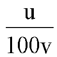
1nr-S1 Needle puncture test Capacity retention (%) after 400 cycles of 1C/1C at 45°C Capacity retention (%) at 60 □ for 60d phenomenon Max. surface temperature /□ Ex.1 0.220 0.00 No smoke and no open flame 181.8 87.0 90.2 Ex.2 0.220 0.00 No smoke and no open flame 183.5 87.0 90.0 Ex.3 0.220 0.00 No smoke and no open flame 185.2 89.8 92.8 Ex.4 0.220 0.00 No smoke and no open flame 183.5 93.0 95.9 Ex.5 0.220 0.08 No smoke and no open flame 178.6 87.0 89.9 Ex.6 0.220 0.16 No smoke and no open flame 186.2 87.0 90.2 Ex.7 0.220 -0.25 No smoke and no open flame 181.4 87.0 90.1 Ex.8 0.006 -0.09 No smoke and no open flame 186.2 83.8 86.8 Ex.9 0.012 0.17 No smoke and no open flame 184.2 87.0 90.1 Ex.10 0.122 -0.16 No smoke and no open flame 175.4 87.0 89.9 Ex.11 0.909 -0.16 No smoke and no open flame 191.7 86.9 90.0 Ex.12 3.659 0.01 No smoke and no open flame 184.3 87.0 89.9 Ex.13 9.091 -0.24 No smoke and no open flame 186.2 86.9 89.9 Ex.14 18.182 0.08 No smoke and no open flame 183.2 87.0 89.9 Ex.15 27.273 0.08 No smoke and no open flame 183.2 84.1 87.0 Ex.16 0.220 -1.06 No smoke and no open flame 186 83.9 87.0 Ex.17 0.220 -0.46 No smoke and no open flame 186.1 86.9 89.9 Ex.18 0.220 1.5 No smoke and no open flame 185.8 86.8 90.1 Ex.19 0.220 1.77 No smoke and no open flame 182.1 84.1 87.0 Ex.20 0.220 1.84 No smoke and no open flame 181.9 83.9 86.9 Ex.21 0.165 0.08 No smoke and no open flame 173.5 83.9 86.9 Ex.22 0.220 0.00 No smoke and no open flame 184.5 87.9 90.7 Ex.23 0.220 0.00 No smoke and no open flame 182.9 90.1 93.0 Ex.24 0.220 0.00 No smoke and no open flame 181.4 93.0 95.9 Ex.25 0.220 0.00 No smoke and no open flame 183.5 92.9 96.0 Ex.26 0.220 0.00 No smoke and no open flame 182.8 93.2 96.0 Ex.27 0.220 0.00 No smoke and no open flame 183.8 89.9 93.1 Ex.28 0.220 0.00 No smoke and no open flame 182.6 88.2 91.0 Ex.29 0.220 -0.08 No smoke and no open flame 182 93.1 96.1 Ex.30 0.220 0.00 No smoke and no open flame 185.3 93.1 96.0 Ex.31 0.220 0.08 No smoke and no open flame 184.7 93.2 96.0 Ex.32 0.220 -0.08 No smoke and no open flame 185.2 93.2 96.0 Ex.33 0.220 0.00 No smoke and no open flame 178.3 86.9 91.0 Ex.34 0.220 0.00 No smoke and no open flame 170.3 87.0 92.1 Ex.35 0.220 0.00 No smoke and no open flame 155.2 87.1 93.9 CEx.1 0.943 -0.08 Smoke and open flame 783.2 87.0 89.9 CEx.2 0.091 0.06 No smoke and no open flame 137.9 75.1 78.1 CEx.3 0.220 0.30 No smoke and no open flame 183.6 75.0 78.0 CEx.4 / 0.16 No smoke and no open flame 182.3 75.1 77.9 CEx.5 / 0.16 No smoke and no open flame 184.5 80.0 82.9 - Comparative analysis of Examples 1 to 7 and Comparative Example 3 showed that the lithium ion secondary batteries in which the positive electrode plate comprised the first positive electrode active material and the second positive electrode active material, and the electrolyte comprised the fluorine-containing lithium salt type additive exhibited significantly improved capacity retention after 400 cycles of 1C/1C at 45°C and capacity retention after 60°C storage for 60 days when the resistivity of the positive electrode plate is less than or equal to 3500Ω•m and that the lithium ion secondary batteries had high safety performance, high temperature storage performance and cycle performance.
- Comparative analysis of Examples 2, 5-7 and 16-20 and Comparative Examples 4-5 showed that the lithium ion secondary batteries in which the positive electrode plate comprised the first positive electrode active material and the second positive electrode active material, and the resistivity of the positive electrode plate is less than or equal to 3500Ω•m exhibited significantly improved capacity retention after 400 cycles of 1C/1C at 45°C and capacity retention after 60°C storage for 60 days when the electrolyte comprised the fluorine-containing lithium salt type additive and that the lithium ion secondary batteries had high safety performance, high temperature storage performance and cycle performance.
- Comparative analysis of Example 11 and Comparative Example 1 showed that when the weight v of manganese element contained in the positive electrode film per unit area of the lithium ion secondary battery is too low, the lithium ion secondary batteries exhibited significantly increased maximum surface temperature and showed smoke and flame phenomenon in needle puncture performance test for lithium ion secondary battery and that the lithium ion secondary battery had lower safety performance. Comparative analysis of Example 21 and Comparative Example 2 shows that when the weight v of manganese element contained in the positive electrode film per unit area of the lithium ion secondary battery is too large, the lithium ion secondary batteries exhibited decreased capacity retention after 400 cycles of 1C/1C at 45°C and capacity retention after 60°C storage for 60 days, resulting in the lithium ion secondary battery having lower high-temperature storage performance and cycle performance. When the weight v of manganese element contained in the positive electrode film per unit area of the lithium ion secondary battery was in the range of 1.1×10⁻³g/cm2∼9.1× 10-3g/cm2, especially in the range of 1.1× 10⁻³g/cm2∼8.2×10-3g/cm2, the lithium ion secondary battery had a higher safety performance, high-temperature storage performance and cycle performance at the same time.
- Comparative analysis of Examples 9 to 14 and Example 8, and Examples 9 to 14 and Example 15 showed that when in the lithium ion secondary battery the ratio of the weight percentage u of the fluorine-containing lithium salt type additive in the electrolyte to the weight v of manganese element contained in the positive electrode film per unit area is too high or too low, the lithium ion secondary battery would exhibit reduced capacity retention after 400 cycles of 1C/1C at 45°C and capacity retention after 60°C storage for 60 days to a certain extent. When the weight percentage of manganese element contained in the positive active material and the weight percentage of the fluorine-containing lithium salt type additive in the electrolyte of the lithium ion secondary battery satisfy the above mentioned relationship (12), the lithium ion secondary battery exhibited a higher safety performance, high-temperature storage performance and cycle performance at the same time.
- Comparative analysis of Examples 17 to 18 and Example 16, and Examples 17 to 18 and Examples 19 to 20 showed that when in the lithium ion secondary battery, the resistivity of the positive electrode plate and the ionic conductivity of the electrolyte had a higher or lower value based on the relationship lnr-s1, the lithium ion secondary battery would exhibit reduced capacity retention after 400 cycles of 1C/1C at 45°C and capacity retention after 60°C storage for 60 days to a certain extent. When the positive electrode plate and the electrolyte of the lithium ion secondary battery satisfy the above mentioned relationship (22), the lithium ion secondary battery exhibited a higher safety performance, high-temperature storage performance and cycle performance at the same time.
- Comparative analysis of Examples 22 to 32 with Examples 2 and 7 showed that by adding a predetermined content of negative electrode film-forming enhancer to the electrolyte, the capacity retention after 400 cycles of 1C/1C at 45°C and capacity retention after 60°C storage for 60 days of the lithium ion secondary battery were further improved to a certain extent and the lithium ion secondary battery exhibited a higher safety performance, high-temperature storage performance and cycle performance at the same time.
- In combination with Examples 1 to 35, it can be seen that the lithium ion secondary battery according to embodiments of the present application can simultaneously exhibit a higher safety performance, high-temperature storage performance, and cycle performance.
- The above mentioned descriptions only show particular implementations of the present application and but are not intended to limit the protection scope of the present application. Any modification or replacement readily figured out by a person skilled in the art within the technical scope disclosed in the present application shall fall within the protection scope of the present application. Therefore, the protection scope of the present application shall be determined by the protection scope of the claims.
Claims (11)
- A lithium ion secondary battery comprising a positive electrode plate, a negative electrode plate, a separator and an electrolyte, wherein
the positive electrode plate comprises a positive electrode current collector and a positive electrode film provided on at least one surface of the positive electrode current collector, and the positive electrode film comprises a first positive electrode active material represented by chemical formula (1) and a second positive electrode active material represented by chemical formula (2),
Li1+xNiaCobMe1-a-bO2-yAy chemical formula (1)
Li1+zMncN2-cO4-dBd chemical formula (2)
in the chemical formula (1), -0.1≤x≤0.2, 0<a<1, 0<b<1, 0<a+b<1, 0≤y<0.2, Me comprises one or more of Mn, Fe, Cr, Ti, Zn, V, Al, Zr and Ce, and A comprises one or more of S, N, F, Cl, Br and I,
in the chemical formula (2), -0.1 ≤ z ≤ 0.2, 0<c≤2, 0≤d<1, N comprises one or more of Ni, Fe, Cr, Ti, Zn, V, Al, Mg, Zr and Ce, and B comprises one or more of S, N, F, Cl, Br and I;
the positive electrode plate has a resistivity r of 3500 Ω·m or less; and,
the electrolyte comprises a fluorine-containing lithium salt type additive. - The lithium ion secondary battery according to claim 1, wherein the resistivity of the positive electrode plate is 2500 Ω·m or less, preferably 1200 Ω·m or less.
- The lithium ion secondary battery according to claim 1, wherein in the chemical formula (1), 0.5≤a<1, 0<b<0.5, 0.7≤a+b<1, 0≤y<0.1, M is one or both of Mn and Al, and A is one or both of S and F.
- The lithium ion secondary battery according to claim 1, wherein the fluorine-containing lithium salt type additive is one or more of a compound represented by chemical formula (3) and a compound represented by chemical formula (4),


in the chemical formula (4), G is one or more of F, Cl, Br and I, and G comprises F, E is P or B, when E is P, x+2y=6, and y is 1 or 2, and when E is B, x+2y=4, and y is 0 or 1. - The lithium ion secondary battery according to claim 4, wherein the fluorine-containing lithium salt type additive is one or more of lithium difluorophosphate LiPO2F2, lithium difluorooxalate phosphate LiDFOP, lithium tetrafluoroborate LiBF4, and lithium difluorooxalate borate LiDFOB.
- The lithium ion secondary battery according to claim 1, wherein the fluorine-containing lithium salt type additive is present in the electrolyte in a weight percentage u of 0.005wt%∼3wt%, preferably 0.1wt%∼2wt% .
- The lithium ion secondary battery according to claim 1, wherein the positive electrode film comprises manganese element in a weight v of 1.1×10⁻³g/cm2∼9.1×10-3g/cm2, preferably 1.1×10⁻³g/cm2∼8.2×10-3g/cm2 per unit area.
- The lithium ion secondary battery according to any one of claims 1 to 7, wherein the positive electrode plate and the electrolyte in the lithium ion secondary battery satisfy the following formula (11)


- The lithium ion secondary battery according to claim 1, wherein the electrolyte further contains a negative electrode film-forming enhancer; and
the negative electrode film-forming enhancer is one or more of cyclic carbonates with unsaturated bonds in side chains, fluorine-containing cyclic carbonates and cyclic sulfonates, preferably one or more of vinyl ethylene carbonate VEC, methylene methanedisulfonate MMDS, difluoroethylene carbonate DFEC, trifluoromethyl ethylene carbonate TFPC, and 1-propene-1,3-sultone PST. - The lithium ion secondary battery according to claim 9, wherein the negative electrode film-forming enhancer is present in the electrolyte in a weight percentage of 0.005wt%-6wt%, more preferably of 0.01wt%-5wt%, more preferably, of 0.1 wt% to 2 wt%.
- The lithium ion secondary battery according to any one of claims 1 to 10, wherein the positive electrode plate and the electrolyte in the lithium ion secondary battery satisfy the following formula (21),


Applications Claiming Priority (2)
| Application Number | Priority Date | Filing Date | Title |
|---|---|---|---|
| CN201811014430.3A CN110875491B (en) | 2018-08-31 | 2018-08-31 | Lithium-ion secondary battery |
| PCT/CN2019/103218 WO2020043153A1 (en) | 2018-08-31 | 2019-08-29 | Secondary lithium ion battery |
Publications (3)
| Publication Number | Publication Date |
|---|---|
| EP3780179A1 true EP3780179A1 (en) | 2021-02-17 |
| EP3780179A4 EP3780179A4 (en) | 2021-07-28 |
| EP3780179B1 EP3780179B1 (en) | 2023-03-22 |
Family
ID=69643949
Family Applications (1)
| Application Number | Title | Priority Date | Filing Date |
|---|---|---|---|
| EP19855763.9A Active EP3780179B1 (en) | 2018-08-31 | 2019-08-29 | Lithium ion secondary battery |
Country Status (9)
| Country | Link |
|---|---|
| US (1) | US11581579B2 (en) |
| EP (1) | EP3780179B1 (en) |
| JP (1) | JP7106746B2 (en) |
| KR (1) | KR102535068B1 (en) |
| CN (2) | CN110875491B (en) |
| HU (1) | HUE061906T2 (en) |
| PL (1) | PL3780179T3 (en) |
| PT (1) | PT3780179T (en) |
| WO (1) | WO2020043153A1 (en) |
Families Citing this family (12)
| Publication number | Priority date | Publication date | Assignee | Title |
|---|---|---|---|---|
| JP7150799B2 (en) | 2020-11-19 | 2022-10-11 | プライムプラネットエナジー&ソリューションズ株式会社 | Non-aqueous electrolyte secondary battery |
| CN115148951A (en) * | 2021-03-31 | 2022-10-04 | 宁德新能源科技有限公司 | Electrochemical device and electronic device |
| EP4421905A4 (en) * | 2021-10-25 | 2025-10-01 | Ningde Amperex Technology Ltd | POSITIVE ELECTRODE, MANUFACTURING METHOD THEREFOR, AND LITHIUM-ION SECONDARY BATTERY |
| CN115832299B (en) * | 2021-10-29 | 2024-09-27 | 宁德时代新能源科技股份有限公司 | Slurry, positive electrode sheet, secondary battery, battery module, battery pack and electrical device |
| CN116848687B (en) * | 2021-11-17 | 2024-11-01 | 宁德时代新能源科技股份有限公司 | Electrolyte, secondary battery, battery module, battery pack, and electricity using device |
| EP4394916A4 (en) * | 2021-11-18 | 2024-10-16 | Ningde Amperex Technology Limited | ELECTROCHEMICAL DEVICE AND ELECTRONIC DEVICE |
| CN114447295B (en) * | 2021-12-28 | 2024-07-02 | 深圳新宙邦科技股份有限公司 | Lithium ion battery |
| CN114566633B (en) * | 2022-03-04 | 2025-02-11 | 中化国际(控股)股份有限公司 | A novel cobalt-free positive electrode material and preparation method thereof |
| KR102852442B1 (en) * | 2022-05-13 | 2025-08-29 | 주식회사 엘지화학 | Life evaluation methode of lithium ion battery |
| CN116314610A (en) * | 2023-04-19 | 2023-06-23 | 欣旺达电动汽车电池有限公司 | A secondary battery and electrical equipment |
| CN117154188B (en) | 2023-10-30 | 2024-04-12 | 宁德时代新能源科技股份有限公司 | Lithium ion battery, battery and power utilization device |
| CN118588868B (en) * | 2024-06-24 | 2025-02-18 | 苏州埃米特材料科技有限公司 | Negative electrode piece and lithium ion secondary battery comprising same and capable of discharging to zero volt |
Family Cites Families (27)
| Publication number | Priority date | Publication date | Assignee | Title |
|---|---|---|---|---|
| EP0954042B1 (en) | 1997-11-19 | 2007-09-05 | Mitsubishi Denki Kabushiki Kaisha | Lithium ion secondary battery and manufacture thereof |
| KR100473433B1 (en) * | 2000-07-17 | 2005-03-08 | 마쯔시다덴기산교 가부시키가이샤 | Non-aqueous electrolyte and non-aqueous electrolytic cell and electrolytic condenser comprising the same |
| JP2004111349A (en) * | 2002-07-23 | 2004-04-08 | Central Glass Co Ltd | Method for avoiding solvent decomposition in electrochemical device, and the electrochemical device using the same |
| CN103811815A (en) * | 2011-01-31 | 2014-05-21 | 三菱化学株式会社 | Nonaqueous electrolytic solution and nonaqueous electrolyte secondary battery using the nonaqueous electrolytic solution |
| JP2014517453A (en) * | 2011-05-23 | 2014-07-17 | エルジー ケム. エルティーディ. | High power lithium secondary battery with improved power density characteristics |
| EP2696409B1 (en) * | 2011-05-23 | 2017-08-09 | LG Chem, Ltd. | High energy density lithium secondary battery having enhanced energy density characteristic |
| JP6098062B2 (en) * | 2011-08-02 | 2017-03-22 | 三菱化学株式会社 | Non-aqueous electrolyte and non-aqueous electrolyte secondary battery using the same |
| JP2015111495A (en) * | 2012-03-29 | 2015-06-18 | 三洋電機株式会社 | Nonaqueous electrolyte secondary battery |
| WO2014175355A1 (en) * | 2013-04-26 | 2014-10-30 | 日産自動車株式会社 | Nonaqueous-electrolyte secondary battery |
| CN103730692A (en) * | 2013-07-18 | 2014-04-16 | 江西优锂新材股份有限公司 | Method for preparing non-aqueous electrolyte suitable for high-energy density lithium ion batteries |
| US9947960B2 (en) * | 2014-02-05 | 2018-04-17 | Johnson Controls Technology Company | Electrolytes for low impedance, wide operating temperature range lithium-ion battery module |
| CN105098177B (en) * | 2014-04-24 | 2018-05-29 | 宁德时代新能源科技股份有限公司 | Secondary lithium battery and preparation method of positive electrode material thereof |
| CN104600314B (en) | 2015-01-04 | 2017-05-03 | 合肥国轩高科动力能源有限公司 | A kind of preparation method of positive pole piece of lithium battery |
| JP6592256B2 (en) * | 2015-03-09 | 2019-10-16 | マクセルホールディングス株式会社 | Lithium ion secondary battery |
| JP6692123B2 (en) * | 2015-03-31 | 2020-05-13 | 株式会社エンビジョンAescジャパン | Lithium ion secondary battery |
| US10644318B2 (en) * | 2015-05-14 | 2020-05-05 | Sekesui Chemical Co., Ltd. | Carbon material, carbon material-active material composite, electrode material for lithium-ion secondary battery, and lithium-ion secondary battery |
| JP7160461B2 (en) | 2015-05-26 | 2022-10-25 | 三井化学株式会社 | Method for manufacturing lithium secondary battery |
| US20180138551A1 (en) * | 2015-05-26 | 2018-05-17 | Mitsui Chemicals, Inc. | Non-aqueous electrolyte solution for battery and lithium secondary battery |
| JP6403285B2 (en) * | 2015-10-30 | 2018-10-10 | オートモーティブエナジーサプライ株式会社 | Lithium ion secondary battery |
| CN105406124B (en) * | 2015-12-31 | 2019-03-19 | 哈尔滨工业大学 | An electrolyte for improving high temperature and high voltage performance of lithium ion battery and its application in lithium ion battery |
| CN107293776A (en) * | 2016-04-12 | 2017-10-24 | 宁德时代新能源科技股份有限公司 | Electrolyte and lithium ion battery |
| CN106025359A (en) * | 2016-07-08 | 2016-10-12 | 珠海市赛纬电子材料股份有限公司 | Lithium ion power battery non-water electrolyte |
| CN106252639A (en) * | 2016-10-17 | 2016-12-21 | 广州天赐高新材料股份有限公司 | A kind of high-capacity lithium ion cell electrolyte, preparation method and lithium ion battery taking into account high temperature performance |
| CN106252716A (en) * | 2016-10-17 | 2016-12-21 | 东莞市凯欣电池材料有限公司 | A kind of safe lithium ion power battery electrolyte and lithium-ion-power cell |
| CN106505249B (en) * | 2016-12-15 | 2021-01-05 | 东莞市杉杉电池材料有限公司 | Lithium ion battery electrolyte and lithium ion battery containing same |
| WO2018155240A1 (en) * | 2017-02-23 | 2018-08-30 | Necエナジーデバイス株式会社 | Positive electrode for lithium ion batteries, and lithium ion battery |
| CN107834110A (en) | 2017-10-26 | 2018-03-23 | 东莞市杉杉电池材料有限公司 | Lithium-ion battery electrolytes and lithium ion battery |
-
2018
- 2018-08-31 CN CN201811014430.3A patent/CN110875491B/en active Active
- 2018-08-31 CN CN202110252353.0A patent/CN112909318B/en active Active
-
2019
- 2019-08-29 HU HUE19855763A patent/HUE061906T2/en unknown
- 2019-08-29 KR KR1020217004931A patent/KR102535068B1/en active Active
- 2019-08-29 WO PCT/CN2019/103218 patent/WO2020043153A1/en not_active Ceased
- 2019-08-29 US US17/052,811 patent/US11581579B2/en active Active
- 2019-08-29 PT PT198557639T patent/PT3780179T/en unknown
- 2019-08-29 PL PL19855763.9T patent/PL3780179T3/en unknown
- 2019-08-29 JP JP2021507947A patent/JP7106746B2/en active Active
- 2019-08-29 EP EP19855763.9A patent/EP3780179B1/en active Active
Also Published As
| Publication number | Publication date |
|---|---|
| JP7106746B2 (en) | 2022-07-26 |
| US20210242498A1 (en) | 2021-08-05 |
| HUE061906T2 (en) | 2023-08-28 |
| KR20210033033A (en) | 2021-03-25 |
| CN110875491B (en) | 2021-03-30 |
| EP3780179B1 (en) | 2023-03-22 |
| CN112909318B (en) | 2022-06-03 |
| JP2021534555A (en) | 2021-12-09 |
| WO2020043153A1 (en) | 2020-03-05 |
| PT3780179T (en) | 2023-04-21 |
| KR102535068B1 (en) | 2023-05-26 |
| CN110875491A (en) | 2020-03-10 |
| EP3780179A4 (en) | 2021-07-28 |
| US11581579B2 (en) | 2023-02-14 |
| PL3780179T3 (en) | 2023-05-29 |
| CN112909318A (en) | 2021-06-04 |
Similar Documents
| Publication | Publication Date | Title |
|---|---|---|
| EP3780179B1 (en) | Lithium ion secondary battery | |
| JP7159459B2 (en) | lithium ion secondary battery | |
| EP3680965B1 (en) | Positive electrode piece and lithium-ion secondary battery | |
| US11355742B2 (en) | Negative electrode plate and lithium-ion secondary battery | |
| US11677074B2 (en) | Positive electrode plate, method for preparing the same and lithium-ion secondary battery | |
| EP3588625B1 (en) | Positive electrode plate and lithium-ion secondary battery | |
| EP3588624B1 (en) | Negative electrode plate, preparation method thereof and electrochemical device | |
| US12444739B2 (en) | Positive electrode plate and lithium-ion secondary battery containing same |
Legal Events
| Date | Code | Title | Description |
|---|---|---|---|
| STAA | Information on the status of an ep patent application or granted ep patent |
Free format text: STATUS: THE INTERNATIONAL PUBLICATION HAS BEEN MADE |
|
| PUAI | Public reference made under article 153(3) epc to a published international application that has entered the european phase |
Free format text: ORIGINAL CODE: 0009012 |
|
| STAA | Information on the status of an ep patent application or granted ep patent |
Free format text: STATUS: REQUEST FOR EXAMINATION WAS MADE |
|
| 17P | Request for examination filed |
Effective date: 20201109 |
|
| AK | Designated contracting states |
Kind code of ref document: A1 Designated state(s): AL AT BE BG CH CY CZ DE DK EE ES FI FR GB GR HR HU IE IS IT LI LT LU LV MC MK MT NL NO PL PT RO RS SE SI SK SM TR |
|
| AX | Request for extension of the european patent |
Extension state: BA ME |
|
| RAP1 | Party data changed (applicant data changed or rights of an application transferred) |
Owner name: CONTEMPORARY AMPEREX TECHNOLOGY CO., LIMITED |
|
| A4 | Supplementary search report drawn up and despatched |
Effective date: 20210625 |
|
| RIC1 | Information provided on ipc code assigned before grant |
Ipc: H01M 4/36 20060101AFI20210621BHEP Ipc: H01M 4/505 20100101ALI20210621BHEP Ipc: H01M 4/525 20100101ALI20210621BHEP Ipc: H01M 4/131 20100101ALI20210621BHEP Ipc: H01M 10/0567 20100101ALI20210621BHEP Ipc: H01M 10/0525 20100101ALN20210621BHEP Ipc: H01M 4/02 20060101ALN20210621BHEP |
|
| DAV | Request for validation of the european patent (deleted) | ||
| DAX | Request for extension of the european patent (deleted) | ||
| STAA | Information on the status of an ep patent application or granted ep patent |
Free format text: STATUS: EXAMINATION IS IN PROGRESS |
|
| 17Q | First examination report despatched |
Effective date: 20220325 |
|
| REG | Reference to a national code |
Ref country code: DE Ref legal event code: R079 Ref document number: 602019026758 Country of ref document: DE Free format text: PREVIOUS MAIN CLASS: H01M0004580000 Ipc: H01M0004360000 |
|
| GRAP | Despatch of communication of intention to grant a patent |
Free format text: ORIGINAL CODE: EPIDOSNIGR1 |
|
| STAA | Information on the status of an ep patent application or granted ep patent |
Free format text: STATUS: GRANT OF PATENT IS INTENDED |
|
| RIC1 | Information provided on ipc code assigned before grant |
Ipc: H01M 4/02 20060101ALN20221209BHEP Ipc: H01M 10/0525 20100101ALN20221209BHEP Ipc: H01M 10/0567 20100101ALI20221209BHEP Ipc: H01M 4/131 20100101ALI20221209BHEP Ipc: H01M 4/525 20100101ALI20221209BHEP Ipc: H01M 4/505 20100101ALI20221209BHEP Ipc: H01M 4/36 20060101AFI20221209BHEP |
|
| INTG | Intention to grant announced |
Effective date: 20230103 |
|
| GRAS | Grant fee paid |
Free format text: ORIGINAL CODE: EPIDOSNIGR3 |
|
| GRAA | (expected) grant |
Free format text: ORIGINAL CODE: 0009210 |
|
| STAA | Information on the status of an ep patent application or granted ep patent |
Free format text: STATUS: THE PATENT HAS BEEN GRANTED |
|
| AK | Designated contracting states |
Kind code of ref document: B1 Designated state(s): AL AT BE BG CH CY CZ DE DK EE ES FI FR GB GR HR HU IE IS IT LI LT LU LV MC MK MT NL NO PL PT RO RS SE SI SK SM TR |
|
| REG | Reference to a national code |
Ref country code: GB Ref legal event code: FG4D |
|
| REG | Reference to a national code |
Ref country code: CH Ref legal event code: EP |
|
| REG | Reference to a national code |
Ref country code: IE Ref legal event code: FG4D |
|
| REG | Reference to a national code |
Ref country code: DE Ref legal event code: R096 Ref document number: 602019026758 Country of ref document: DE |
|
| REG | Reference to a national code |
Ref country code: AT Ref legal event code: REF Ref document number: 1555842 Country of ref document: AT Kind code of ref document: T Effective date: 20230415 |
|
| REG | Reference to a national code |
Ref country code: PT Ref legal event code: SC4A Ref document number: 3780179 Country of ref document: PT Date of ref document: 20230421 Kind code of ref document: T Free format text: AVAILABILITY OF NATIONAL TRANSLATION Effective date: 20230417 |
|
| P01 | Opt-out of the competence of the unified patent court (upc) registered |
Effective date: 20230516 |
|
| REG | Reference to a national code |
Ref country code: LT Ref legal event code: MG9D |
|
| REG | Reference to a national code |
Ref country code: NL Ref legal event code: MP Effective date: 20230322 |
|
| PG25 | Lapsed in a contracting state [announced via postgrant information from national office to epo] |
Ref country code: RS Free format text: LAPSE BECAUSE OF FAILURE TO SUBMIT A TRANSLATION OF THE DESCRIPTION OR TO PAY THE FEE WITHIN THE PRESCRIBED TIME-LIMIT Effective date: 20230322 Ref country code: NO Free format text: LAPSE BECAUSE OF FAILURE TO SUBMIT A TRANSLATION OF THE DESCRIPTION OR TO PAY THE FEE WITHIN THE PRESCRIBED TIME-LIMIT Effective date: 20230622 Ref country code: LV Free format text: LAPSE BECAUSE OF FAILURE TO SUBMIT A TRANSLATION OF THE DESCRIPTION OR TO PAY THE FEE WITHIN THE PRESCRIBED TIME-LIMIT Effective date: 20230322 Ref country code: LT Free format text: LAPSE BECAUSE OF FAILURE TO SUBMIT A TRANSLATION OF THE DESCRIPTION OR TO PAY THE FEE WITHIN THE PRESCRIBED TIME-LIMIT Effective date: 20230322 Ref country code: HR Free format text: LAPSE BECAUSE OF FAILURE TO SUBMIT A TRANSLATION OF THE DESCRIPTION OR TO PAY THE FEE WITHIN THE PRESCRIBED TIME-LIMIT Effective date: 20230322 |
|
| REG | Reference to a national code |
Ref country code: AT Ref legal event code: MK05 Ref document number: 1555842 Country of ref document: AT Kind code of ref document: T Effective date: 20230322 |
|
| REG | Reference to a national code |
Ref country code: HU Ref legal event code: AG4A Ref document number: E061906 Country of ref document: HU |
|
| PG25 | Lapsed in a contracting state [announced via postgrant information from national office to epo] |
Ref country code: SE Free format text: LAPSE BECAUSE OF FAILURE TO SUBMIT A TRANSLATION OF THE DESCRIPTION OR TO PAY THE FEE WITHIN THE PRESCRIBED TIME-LIMIT Effective date: 20230322 Ref country code: NL Free format text: LAPSE BECAUSE OF FAILURE TO SUBMIT A TRANSLATION OF THE DESCRIPTION OR TO PAY THE FEE WITHIN THE PRESCRIBED TIME-LIMIT Effective date: 20230322 Ref country code: GR Free format text: LAPSE BECAUSE OF FAILURE TO SUBMIT A TRANSLATION OF THE DESCRIPTION OR TO PAY THE FEE WITHIN THE PRESCRIBED TIME-LIMIT Effective date: 20230623 Ref country code: FI Free format text: LAPSE BECAUSE OF FAILURE TO SUBMIT A TRANSLATION OF THE DESCRIPTION OR TO PAY THE FEE WITHIN THE PRESCRIBED TIME-LIMIT Effective date: 20230322 |
|
| PG25 | Lapsed in a contracting state [announced via postgrant information from national office to epo] |
Ref country code: SM Free format text: LAPSE BECAUSE OF FAILURE TO SUBMIT A TRANSLATION OF THE DESCRIPTION OR TO PAY THE FEE WITHIN THE PRESCRIBED TIME-LIMIT Effective date: 20230322 Ref country code: RO Free format text: LAPSE BECAUSE OF FAILURE TO SUBMIT A TRANSLATION OF THE DESCRIPTION OR TO PAY THE FEE WITHIN THE PRESCRIBED TIME-LIMIT Effective date: 20230322 Ref country code: ES Free format text: LAPSE BECAUSE OF FAILURE TO SUBMIT A TRANSLATION OF THE DESCRIPTION OR TO PAY THE FEE WITHIN THE PRESCRIBED TIME-LIMIT Effective date: 20230322 Ref country code: EE Free format text: LAPSE BECAUSE OF FAILURE TO SUBMIT A TRANSLATION OF THE DESCRIPTION OR TO PAY THE FEE WITHIN THE PRESCRIBED TIME-LIMIT Effective date: 20230322 Ref country code: AT Free format text: LAPSE BECAUSE OF FAILURE TO SUBMIT A TRANSLATION OF THE DESCRIPTION OR TO PAY THE FEE WITHIN THE PRESCRIBED TIME-LIMIT Effective date: 20230322 |
|
| PG25 | Lapsed in a contracting state [announced via postgrant information from national office to epo] |
Ref country code: SK Free format text: LAPSE BECAUSE OF FAILURE TO SUBMIT A TRANSLATION OF THE DESCRIPTION OR TO PAY THE FEE WITHIN THE PRESCRIBED TIME-LIMIT Effective date: 20230322 Ref country code: IS Free format text: LAPSE BECAUSE OF FAILURE TO SUBMIT A TRANSLATION OF THE DESCRIPTION OR TO PAY THE FEE WITHIN THE PRESCRIBED TIME-LIMIT Effective date: 20230722 |
|
| REG | Reference to a national code |
Ref country code: DE Ref legal event code: R097 Ref document number: 602019026758 Country of ref document: DE |
|
| PLBE | No opposition filed within time limit |
Free format text: ORIGINAL CODE: 0009261 |
|
| STAA | Information on the status of an ep patent application or granted ep patent |
Free format text: STATUS: NO OPPOSITION FILED WITHIN TIME LIMIT |
|
| PG25 | Lapsed in a contracting state [announced via postgrant information from national office to epo] |
Ref country code: SI Free format text: LAPSE BECAUSE OF FAILURE TO SUBMIT A TRANSLATION OF THE DESCRIPTION OR TO PAY THE FEE WITHIN THE PRESCRIBED TIME-LIMIT Effective date: 20230322 Ref country code: DK Free format text: LAPSE BECAUSE OF FAILURE TO SUBMIT A TRANSLATION OF THE DESCRIPTION OR TO PAY THE FEE WITHIN THE PRESCRIBED TIME-LIMIT Effective date: 20230322 Ref country code: CZ Free format text: LAPSE BECAUSE OF FAILURE TO SUBMIT A TRANSLATION OF THE DESCRIPTION OR TO PAY THE FEE WITHIN THE PRESCRIBED TIME-LIMIT Effective date: 20230322 |
|
| 26N | No opposition filed |
Effective date: 20240102 |
|
| PG25 | Lapsed in a contracting state [announced via postgrant information from national office to epo] |
Ref country code: MC Free format text: LAPSE BECAUSE OF FAILURE TO SUBMIT A TRANSLATION OF THE DESCRIPTION OR TO PAY THE FEE WITHIN THE PRESCRIBED TIME-LIMIT Effective date: 20230322 |
|
| REG | Reference to a national code |
Ref country code: CH Ref legal event code: PL |
|
| PG25 | Lapsed in a contracting state [announced via postgrant information from national office to epo] |
Ref country code: MC Free format text: LAPSE BECAUSE OF FAILURE TO SUBMIT A TRANSLATION OF THE DESCRIPTION OR TO PAY THE FEE WITHIN THE PRESCRIBED TIME-LIMIT Effective date: 20230322 |
|
| PG25 | Lapsed in a contracting state [announced via postgrant information from national office to epo] |
Ref country code: LU Free format text: LAPSE BECAUSE OF NON-PAYMENT OF DUE FEES Effective date: 20230829 |
|
| PG25 | Lapsed in a contracting state [announced via postgrant information from national office to epo] |
Ref country code: LU Free format text: LAPSE BECAUSE OF NON-PAYMENT OF DUE FEES Effective date: 20230829 Ref country code: CH Free format text: LAPSE BECAUSE OF NON-PAYMENT OF DUE FEES Effective date: 20230831 |
|
| REG | Reference to a national code |
Ref country code: BE Ref legal event code: MM Effective date: 20230831 |
|
| REG | Reference to a national code |
Ref country code: IE Ref legal event code: MM4A |
|
| PG25 | Lapsed in a contracting state [announced via postgrant information from national office to epo] |
Ref country code: IT Free format text: LAPSE BECAUSE OF FAILURE TO SUBMIT A TRANSLATION OF THE DESCRIPTION OR TO PAY THE FEE WITHIN THE PRESCRIBED TIME-LIMIT Effective date: 20230322 |
|
| PG25 | Lapsed in a contracting state [announced via postgrant information from national office to epo] |
Ref country code: IE Free format text: LAPSE BECAUSE OF NON-PAYMENT OF DUE FEES Effective date: 20230829 |
|
| PG25 | Lapsed in a contracting state [announced via postgrant information from national office to epo] |
Ref country code: IE Free format text: LAPSE BECAUSE OF NON-PAYMENT OF DUE FEES Effective date: 20230829 |
|
| REG | Reference to a national code |
Ref country code: DE Ref legal event code: R081 Ref document number: 602019026758 Country of ref document: DE Owner name: CONTEMPORARY AMPEREX TECHNOLOGY (HONG KONG) LI, HK Free format text: FORMER OWNER: CONTEMPORARY AMPEREX TECHNOLOGY CO., LIMITED, NINGDE, FUJIAN, CN |
|
| PG25 | Lapsed in a contracting state [announced via postgrant information from national office to epo] |
Ref country code: BE Free format text: LAPSE BECAUSE OF NON-PAYMENT OF DUE FEES Effective date: 20230831 |
|
| REG | Reference to a national code |
Ref country code: GB Ref legal event code: 732E Free format text: REGISTERED BETWEEN 20240822 AND 20240828 |
|
| REG | Reference to a national code |
Ref country code: HU Ref legal event code: GB9C Owner name: CONTEMPORARY AMPEREX TECHNOLOGY (HONG KONG) LIMITED, HK Free format text: FORMER OWNER(S): CONTEMPORARY AMPEREX TECHNOLOGY CO., LIMITED, CN Ref country code: HU Ref legal event code: FH1C Free format text: FORMER REPRESENTATIVE(S): SBGK SZABADALMI UEGYVIVOEI IRODA, HU Representative=s name: DANUBIA SZABADALMI ES JOGI IRODA KFT., HU |
|
| PG25 | Lapsed in a contracting state [announced via postgrant information from national office to epo] |
Ref country code: BG Free format text: LAPSE BECAUSE OF FAILURE TO SUBMIT A TRANSLATION OF THE DESCRIPTION OR TO PAY THE FEE WITHIN THE PRESCRIBED TIME-LIMIT Effective date: 20230322 |
|
| PG25 | Lapsed in a contracting state [announced via postgrant information from national office to epo] |
Ref country code: BG Free format text: LAPSE BECAUSE OF FAILURE TO SUBMIT A TRANSLATION OF THE DESCRIPTION OR TO PAY THE FEE WITHIN THE PRESCRIBED TIME-LIMIT Effective date: 20230322 |
|
| PG25 | Lapsed in a contracting state [announced via postgrant information from national office to epo] |
Ref country code: CY Free format text: LAPSE BECAUSE OF FAILURE TO SUBMIT A TRANSLATION OF THE DESCRIPTION OR TO PAY THE FEE WITHIN THE PRESCRIBED TIME-LIMIT; INVALID AB INITIO Effective date: 20190829 |
|
| PGFP | Annual fee paid to national office [announced via postgrant information from national office to epo] |
Ref country code: HU Payment date: 20250728 Year of fee payment: 7 |
|
| PGFP | Annual fee paid to national office [announced via postgrant information from national office to epo] |
Ref country code: PT Payment date: 20250820 Year of fee payment: 7 |
|
| PGFP | Annual fee paid to national office [announced via postgrant information from national office to epo] |
Ref country code: DE Payment date: 20250702 Year of fee payment: 7 |
|
| PGFP | Annual fee paid to national office [announced via postgrant information from national office to epo] |
Ref country code: GB Payment date: 20250703 Year of fee payment: 7 |
|
| PGFP | Annual fee paid to national office [announced via postgrant information from national office to epo] |
Ref country code: FR Payment date: 20250703 Year of fee payment: 7 |
|
| PG25 | Lapsed in a contracting state [announced via postgrant information from national office to epo] |
Ref country code: TR Free format text: LAPSE BECAUSE OF FAILURE TO SUBMIT A TRANSLATION OF THE DESCRIPTION OR TO PAY THE FEE WITHIN THE PRESCRIBED TIME-LIMIT Effective date: 20230322 |
|
| PGFP | Annual fee paid to national office [announced via postgrant information from national office to epo] |
Ref country code: PL Payment date: 20250612 Year of fee payment: 7 |