EP3780056A1 - Ventilating insulating member for interrupter units - Google Patents
Ventilating insulating member for interrupter units Download PDFInfo
- Publication number
- EP3780056A1 EP3780056A1 EP19192095.8A EP19192095A EP3780056A1 EP 3780056 A1 EP3780056 A1 EP 3780056A1 EP 19192095 A EP19192095 A EP 19192095A EP 3780056 A1 EP3780056 A1 EP 3780056A1
- Authority
- EP
- European Patent Office
- Prior art keywords
- ventilating
- housing
- insulating member
- interrupter
- interrupter unit
- Prior art date
- Legal status (The legal status is an assumption and is not a legal conclusion. Google has not performed a legal analysis and makes no representation as to the accuracy of the status listed.)
- Granted
Links
Images


Classifications
-
- H—ELECTRICITY
- H01—ELECTRIC ELEMENTS
- H01H—ELECTRIC SWITCHES; RELAYS; SELECTORS; EMERGENCY PROTECTIVE DEVICES
- H01H33/00—High-tension or heavy-current switches with arc-extinguishing or arc-preventing means
- H01H33/60—Switches wherein the means for extinguishing or preventing the arc do not include separate means for obtaining or increasing flow of arc-extinguishing fluid
- H01H33/66—Vacuum switches
- H01H33/662—Housings or protective screens
- H01H33/66207—Specific housing details, e.g. sealing, soldering or brazing
-
- H—ELECTRICITY
- H01—ELECTRIC ELEMENTS
- H01H—ELECTRIC SWITCHES; RELAYS; SELECTORS; EMERGENCY PROTECTIVE DEVICES
- H01H33/00—High-tension or heavy-current switches with arc-extinguishing or arc-preventing means
- H01H33/60—Switches wherein the means for extinguishing or preventing the arc do not include separate means for obtaining or increasing flow of arc-extinguishing fluid
- H01H33/66—Vacuum switches
-
- H—ELECTRICITY
- H01—ELECTRIC ELEMENTS
- H01H—ELECTRIC SWITCHES; RELAYS; SELECTORS; EMERGENCY PROTECTIVE DEVICES
- H01H9/00—Details of switching devices, not covered by groups H01H1/00 - H01H7/00
- H01H9/52—Cooling of switch parts
-
- H—ELECTRICITY
- H01—ELECTRIC ELEMENTS
- H01H—ELECTRIC SWITCHES; RELAYS; SELECTORS; EMERGENCY PROTECTIVE DEVICES
- H01H9/00—Details of switching devices, not covered by groups H01H1/00 - H01H7/00
- H01H9/52—Cooling of switch parts
- H01H2009/526—Cooling of switch parts of the high voltage switches
-
- H—ELECTRICITY
- H01—ELECTRIC ELEMENTS
- H01H—ELECTRIC SWITCHES; RELAYS; SELECTORS; EMERGENCY PROTECTIVE DEVICES
- H01H33/00—High-tension or heavy-current switches with arc-extinguishing or arc-preventing means
- H01H33/60—Switches wherein the means for extinguishing or preventing the arc do not include separate means for obtaining or increasing flow of arc-extinguishing fluid
- H01H33/66—Vacuum switches
- H01H33/662—Housings or protective screens
- H01H33/66207—Specific housing details, e.g. sealing, soldering or brazing
- H01H2033/6623—Details relating to the encasing or the outside layers of the vacuum switch housings
Definitions
- the present disclosure relates to switching devices such as circuit breakers. More particularly, the present disclosure relates to a ventilating insulating member for interrupter units of circuit breakers.
- a switching device such as a circuit breaker mainly includes a switching module formed from one or more function-oriented units including a base module unit, a pole module unit and a drive module unit.
- the pole module unit includes an interrupter unit such as a vacuum interrupter comprising a stationary member and a movable member.
- circuit breakers are switches used to protect electrical circuitry connected thereto from damage due to overload, by their automatic operation leading to an interruption of the current flowing therethrough.
- Vacuum circuit breakers typically have a pair of electrical switching contacts arranged inside a vacuum chamber. Vacuum circuit breakers interrupt current by opening of these switching contacts in vacuum. Vacuum circuit breakers are an essential component especially in the medium voltage electrical protection equipment. For high voltage applications interrupter units might be filed with gas such as SF6 for both insulation and interruption.
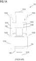
- FIG 1A illustrates a sectional elevation view of a vacuum interrupter 100 according to the state of the art.
- the vacuum interrupter 100 comprises a housing 101 comprising a ceramic housing 101A and a metallic housing 101B rigidly attached to one another.
- the housing 101 houses a metallic vapour shield 102 there-within.
- the metallic vapour shield 102 in turn houses the electrical contacts 103A, 103B, that is, a fixed contact 103A rigidly connected to a fixed contact stem 107A and a moving contact 103B operably connected to a moving contact stem 107B via bellows 104 that allow movement of the moving contact 103B.
- a moving contact guide 106 guides the movement of the moving contact 103B with help of the bellows 104.
- the electrical contacts 103A and 103B physically separate in a vacuum chamber defined within the ceramic housing 101A.
- the metallic vapour shield 102 and the ceramic housing 101A are connected with each other in a leak proof manner so as to maintain vacuum inside the vacuum interrupter 100.
- the metallic housing 101B and the ceramic housing 101A are connected to one another in a leakproof manner.
- the metallic vapour shield 102 and the ceramic housing 101A as well as the metallic housing 101B and the ceramic housing 101A are joined via a process of brazing which leads to formation of solder edges (not shown) in the contact areas 105A and 105B, where the metallic vapour shield 102 and the ceramic housing 101A and/or the metallic housing 101B and the ceramic housing 101A form a physical joint there-between.
- solder edges although very small in size typically assume sharp edges which result in high electrical field strengths. In consequence, these solder edges when formed across vacuum interrupters 100, might lead to unwanted flashovers and risks posed to equipment as well as human life if dieletric distances are small.
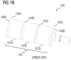
- FIG 1B illustrates a perspective view of a vacuum interrupter 100 according to state of the art.
- the vacuum interrupter 100 has contact areas 105A and 105B along its body on which the solder edges (not shown) are formed due to a physical connection made during aforementioned construction of the vacuum interrupter 100. These solder edges typically form in the areas 105A lying towards distal ends 108A and 108B of the vacuum interrupter 100. However, they may also form along surfaces 105B where the metallic housing 101B and the ceramic housing 101A are physically connected with one another.
- an object of the present invention to provide an interrupter unit suitable for air insulated as well as gas insulated applications, that addresses the problems arising from the solder edge formation, in a time-effective, design-effective and cost-effective manner.
- the interrupter unit disclosed herein achieves the aforementioned object by a ventilating insulating member physically disposable on the housing accommodating at least one of the contact areas and therefore, the solder edges, thereby, precluding aforementioned problems arising due to formation of the solder edges.
- interrupter unit refers to a switching unit having electrical contacts that make or break a circuit to allow or interrupt current flow there-between.
- the interrupter unit is a vacuum interrupter unit which separates its electrical contacts in vacuum which has maximal dielectric strength.
- the interrupter unit comprises a housing.
- the housing includes a non-metallic housing such as a ceramic housing or a glass housing, and a metallic housing, in contact with one another forming one or more contact areas therebetween.
- contact areas refer to physical points of contact between two dissimilar material components of the interrupter unit. For example, contact areas are points of contact between the ceramic housing and the metallic housing or between the ceramic housing and the metallic vapor shield shielding electrical contacts of the interrupter unit, placed inside the housing.
- the interrupter unit comprises a ventilating insulating member physically disposable on the housing accommodating at least one of the contact areas.
- ventilation insulating member refers to a layer having an insulating material therein and configured so as to cover one or more of the contact areas while providing ventilation at least partially to the one or more contact areas.
- the insulating ventilating member is configured as an auto-shrinkable cap which has a circumference lesser than a circumference of the housing of the interrupter unit such that when the insulating ventilating member is stretched and aligned on the housing to cover one or more of the contact areas and is released it automatically shrinks on the contact area.
- the ventilating insulating member comprises protrusions and/or indentations along an inner surface of the ventilating insulating member.
- the ventilating insulating member comprises orifices along an inner surface of the ventilating insulating member. These protrusions, indentations, and/or orifices are provided, for example, in form of ribs, grooves, holes, corrugations, and/or a combination thereof, along the inner surface of the ventilating insulating member so as to allow formation of a gap between the housing and the insulating ventilating member that allows air to escape therethrough.
- the protrusions, indentations, and/or orifices are configured in one of multiple aspects involving but not limited to a vertical alignment with respect to the housing, a horizontal alignment with respect to the housing, an oblique alignment with respect to the housing, and/or a combination thereof.
- a number of the protrusions, indentations, and/or orifices, and a physical alignment thereof is determined based on an amount of grip to be exerted onto the housing, a construction of the interrupter unit, and ensuring effective removal of air through the ventilating insulating member.
- the ventilating properties of the insulating ventilating member allows it to be used in gas insulated applications.
- the vacuum interrupter unit is immersed and retained under pressure in a container filled with an insulating gas.
- the container is evacuated and air from within the container is drawn, so as to create vacuum, and finally the container is filled up with insulating gas.
- the ventilating properties of the insulating ventilating member preclude retention of air under the ventilating insulating member while air is being drawn out of the container.
- this ventilating property also allows the insulating ventilating member to maintain its position upon the housing even during changes in the air pressure during evacuation. Furthermore, the ventilating property also ensures complete removal of air the container.
- the ventilating insulating member is suited for gas-insulated application with vacuum tubes used in gas-containers of gas insulated switchgears
- the ventilating insulating member is flexibly disposable on the housing so as to accommodate one or more of the contact areas.
- the insulating ventilating member is configured as an annular member covering only the contact area(s).
- the insulating ventilating member extends to cover more than one contact area.
- this aspect allows coverage of more than one contact area and therefore, solder edges that may be formed along various contact areas of the ceramic housing and the metallic housing.
- the ventilating insulating member is made of an elastomer material such as silicone.
- the insulating ventilating member is made only of elastomer.
- the insulating ventilating member is made of a composite material having elastomer.
- the insulating ventilating member is made of a graded material having elastomer, to cover one or more of the contact areas.
- the switching device is, for example, a circuit breaker arrangement.
- the circuit breaker arrangement comprises a pole module unit and a drive module unit operably connected to the pole module unit.
- the pole module unit comprises the aforementioned interrupter unit.
- the circuit breaker arrangement is a vacuum circuit breaker.
- a switchgear arrangement comprising a cable compartment, a busbar compartment, and a switching compartment having the aforementioned circuit breaker arrangement including the interrupter unit.
- the switchgear arrangement is an air-insulated switchgear, a vacuum insulated switchgear or a gas insulated switchgear.
- FIG 2A illustrates a perspective view of a vacuum interrupter 200 having ventilating insulating caps 201 each covering a contact area 105A shown in FIG 1B , according to an embodiment of the insulating ventilating member disclosed herein.
- the ventilating insulating caps 201 are flexibly positioned, that is, expanded and/or stretched over the ceramic housing 101A and positioned so as to cover the contact areas 105A, thereby, precluding any affects of the solder edges (not shown) formed in these contact areas 105A.
- FIG 2B illustrates a perspective view of a vacuum interrupter 200 having an ventilating insulating cap 201 covering more than one contact areas 105A and 105B shown in FIG 1B , according to an embodiment of the insulating ventilating member disclosed herein.
- the ventilating insulating cap 201 as shown in FIG 2B is configured so as to flexibly expand over the ceramic housing 101A covering the contact area 105A and extending along the ceramic housing 101A up till the metallic housing 101B so as to cover the contact area 105B.
- This arrangement of the ventilating insulating cap provides additional coverage of the solder edges (not shown) formed in various contact areas 105A and 105B.
- FIG 3 illustrates an ventilating insulating cap 201, according to an embodiment of the insulating ventilating member disclosed herein.
- the ventilating insulating cap 201 is a circular shaped cap and/or a sleeve configured to suit the vacuum interrupter 200 shown in FIGS 2A and 2B .
- the ventilating insulating cap 201 is flexibly positioned on the ceramic housing 101A such that a bottom surface 201B of the ventilating insulating cap 201 is in a direct physical contact with the distal end 108A or 108B of the vacuum interrupter 200 shown in FIG 2A , and an inner surface 201C of the ventilating insulating cap 201 is completely disposed against the contact area(s) 105A and/or 105B and at least partially disposed against the ceramic housing 101A.
- the ventilating insulating cap 201 includes protrusions, that is, ribs 201A along the inner surface 201C extending till the bottom surface 201B to allow a gap to be maintained throughout a height H of the ventilating insulating cap 201 thereby, enabling air to escape therefrom effectively.
- FIG 4 illustrates a circuit breaker arrangement 400 having a vacuum interrupter 200 shown in FIG 2A or FIG 2B .
- the circuit breaker arrangement 400 comprises a pole module unit 401 and a drive module unit 402 operably connected to the pole module unit 401 via pole insulators 403 and an insulating coupler 404.
- the pole module unit 401 comprises the aforementioned vacuum interrupter 200.
- the circuit breaker arrangement 400 is a vacuum circuit breaker.
- FIG 5 illustrates a switchgear arrangement 500 having the circuit breaker arrangement 400 shown in FIG 4 including the vacuum interrupter 200.
- the switchgear arrangement 500 comprises a cable compartment 501, a switching compartment 502 having the aforementioned circuit breaker arrangement 400 including the interrupter unit 200 shown in FIG 4 , and a busbar compartment 503 all coupled with one another.
Landscapes
- High-Tension Arc-Extinguishing Switches Without Spraying Means (AREA)
- Gas-Insulated Switchgears (AREA)
Abstract
Description
- The present disclosure relates to switching devices such as circuit breakers. More particularly, the present disclosure relates to a ventilating insulating member for interrupter units of circuit breakers.
- Conventionally, a switching device such as a circuit breaker mainly includes a switching module formed from one or more function-oriented units including a base module unit, a pole module unit and a drive module unit. The pole module unit includes an interrupter unit such as a vacuum interrupter comprising a stationary member and a movable member. Typically, circuit breakers are switches used to protect electrical circuitry connected thereto from damage due to overload, by their automatic operation leading to an interruption of the current flowing therethrough. Vacuum circuit breakers typically have a pair of electrical switching contacts arranged inside a vacuum chamber. Vacuum circuit breakers interrupt current by opening of these switching contacts in vacuum. Vacuum circuit breakers are an essential component especially in the medium voltage electrical protection equipment. For high voltage applications interrupter units might be filed with gas such as SF6 for both insulation and interruption.
-
FIG 1A illustrates a sectional elevation view of avacuum interrupter 100 according to the state of the art. Thevacuum interrupter 100 comprises ahousing 101 comprising aceramic housing 101A and ametallic housing 101B rigidly attached to one another. Thehousing 101 houses ametallic vapour shield 102 there-within. Themetallic vapour shield 102 in turn houses theelectrical contacts contact 103A rigidly connected to afixed contact stem 107A and a movingcontact 103B operably connected to a movingcontact stem 107B viabellows 104 that allow movement of the movingcontact 103B. A movingcontact guide 106 guides the movement of the movingcontact 103B with help of thebellows 104. Theelectrical contacts ceramic housing 101A. Typically, themetallic vapour shield 102 and theceramic housing 101A are connected with each other in a leak proof manner so as to maintain vacuum inside thevacuum interrupter 100. Similarly, themetallic housing 101B and theceramic housing 101A are connected to one another in a leakproof manner. - During construction of the
vacuum interrupter 100 themetallic vapour shield 102 and theceramic housing 101A as well as themetallic housing 101B and theceramic housing 101A are joined via a process of brazing which leads to formation of solder edges (not shown) in thecontact areas metallic vapour shield 102 and theceramic housing 101A and/or themetallic housing 101B and theceramic housing 101A form a physical joint there-between. These solder edges although very small in size typically assume sharp edges which result in high electrical field strengths. In consequence, these solder edges when formed acrossvacuum interrupters 100, might lead to unwanted flashovers and risks posed to equipment as well as human life if dieletric distances are small. -
FIG 1B illustrates a perspective view of avacuum interrupter 100 according to state of the art. Thevacuum interrupter 100 hascontact areas vacuum interrupter 100. These solder edges typically form in theareas 105A lying towardsdistal ends vacuum interrupter 100. However, they may also form alongsurfaces 105B where themetallic housing 101B and theceramic housing 101A are physically connected with one another. - Techniques known in the art that address aforementioned problems arising due to formation of solder edges (not shown) include constructing vacuum tubes re-casted with special materials such as an elastomer, shrink tubes that are shrunk onto the vacuum tubes or on the solder edges per se, application of a self-adhesive tape under mechanical stress onto the solder edges, usage of field control elements, that is, electrodes through which the solder edges can be placed in a field shadow, etc. However, these techniques are rather time, design and cost intensive.
- Accordingly, it is an object of the present invention, to provide an interrupter unit suitable for air insulated as well as gas insulated applications, that addresses the problems arising from the solder edge formation, in a time-effective, design-effective and cost-effective manner.
- The interrupter unit disclosed herein achieves the aforementioned object by a ventilating insulating member physically disposable on the housing accommodating at least one of the contact areas and therefore, the solder edges, thereby, precluding aforementioned problems arising due to formation of the solder edges.
- Disclosed herein is an interrupter unit. As used herein, "interrupter unit" refers to a switching unit having electrical contacts that make or break a circuit to allow or interrupt current flow there-between. According to one aspect, the interrupter unit is a vacuum interrupter unit which separates its electrical contacts in vacuum which has maximal dielectric strength. The interrupter unit comprises a housing. The housing includes a non-metallic housing such as a ceramic housing or a glass housing, and a metallic housing, in contact with one another forming one or more contact areas therebetween. As used herein, "contact areas" refer to physical points of contact between two dissimilar material components of the interrupter unit. For example, contact areas are points of contact between the ceramic housing and the metallic housing or between the ceramic housing and the metallic vapor shield shielding electrical contacts of the interrupter unit, placed inside the housing.
- The interrupter unit comprises a ventilating insulating member physically disposable on the housing accommodating at least one of the contact areas. As used herein, "ventilating insulating member" refers to a layer having an insulating material therein and configured so as to cover one or more of the contact areas while providing ventilation at least partially to the one or more contact areas. Advantageously, the insulating ventilating member is configured as an auto-shrinkable cap which has a circumference lesser than a circumference of the housing of the interrupter unit such that when the insulating ventilating member is stretched and aligned on the housing to cover one or more of the contact areas and is released it automatically shrinks on the contact area.
- According to one aspect, the ventilating insulating member comprises protrusions and/or indentations along an inner surface of the ventilating insulating member. According to another aspect, the ventilating insulating member comprises orifices along an inner surface of the ventilating insulating member. These protrusions, indentations, and/or orifices are provided, for example, in form of ribs, grooves, holes, corrugations, and/or a combination thereof, along the inner surface of the ventilating insulating member so as to allow formation of a gap between the housing and the insulating ventilating member that allows air to escape therethrough. Advantageously, the protrusions, indentations, and/or orifices are configured in one of multiple aspects involving but not limited to a vertical alignment with respect to the housing, a horizontal alignment with respect to the housing, an oblique alignment with respect to the housing, and/or a combination thereof. Advantageously, a number of the protrusions, indentations, and/or orifices, and a physical alignment thereof is determined based on an amount of grip to be exerted onto the housing, a construction of the interrupter unit, and ensuring effective removal of air through the ventilating insulating member.
- These protrusions and indentations enable the ventilating insulating member to provide ventilation to the contact area(s). Advantageously, the ventilating properties of the insulating ventilating member allows it to be used in gas insulated applications. In gas insulated applications the vacuum interrupter unit is immersed and retained under pressure in a container filled with an insulating gas. To fill the container with the insulating gas, the container is evacuated and air from within the container is drawn, so as to create vacuum, and finally the container is filled up with insulating gas. The ventilating properties of the insulating ventilating member preclude retention of air under the ventilating insulating member while air is being drawn out of the container. Moreover, this ventilating property also allows the insulating ventilating member to maintain its position upon the housing even during changes in the air pressure during evacuation. Furthermore, the ventilating property also ensures complete removal of air the container. Thus, the ventilating insulating member is suited for gas-insulated application with vacuum tubes used in gas-containers of gas insulated switchgears
- The ventilating insulating member is flexibly disposable on the housing so as to accommodate one or more of the contact areas. Advantageously, the insulating ventilating member is configured as an annular member covering only the contact area(s). According to one aspect, the insulating ventilating member extends to cover more than one contact area. Advantageously, this aspect allows coverage of more than one contact area and therefore, solder edges that may be formed along various contact areas of the ceramic housing and the metallic housing. Advantageously, the ventilating insulating member is made of an elastomer material such as silicone. According to one aspect, the insulating ventilating member is made only of elastomer. According to another aspect, the insulating ventilating member is made of a composite material having elastomer. According to yet another aspect, the insulating ventilating member is made of a graded material having elastomer, to cover one or more of the contact areas.
- Also, disclosed herein, is a switching device. The switching device is, for example, a circuit breaker arrangement. The circuit breaker arrangement comprises a pole module unit and a drive module unit operably connected to the pole module unit. The pole module unit comprises the aforementioned interrupter unit. The circuit breaker arrangement is a vacuum circuit breaker.
- Also, disclosed herein, is a switchgear arrangement comprising a cable compartment, a busbar compartment, and a switching compartment having the aforementioned circuit breaker arrangement including the interrupter unit. The switchgear arrangement is an air-insulated switchgear, a vacuum insulated switchgear or a gas insulated switchgear.
- The above mentioned and other features of the invention will now be addressed with reference to the accompanying drawings of the present invention. The illustrated embodiments are intended to illustrated, but not limit the invention.
- The present invention is further described hereinafter with reference to illustrated embodiments shown in the accompanying drawings, in which:
- FIG 1A
- illustrates a sectional elevation view of a vacuum interrupter according to the state of the art.
- FIG 1B
- illustrates a perspective view of a vacuum interrupter according to the state of the art.
- FIG 2A
- illustrates a perspective view of a vacuum interrupter having ventilating insulating caps each covering a contact area, according to an embodiment of the insulating ventilating member disclosed herein.
- FIG 2B
- illustrates a perspective view of a vacuum interrupter having an ventilating insulating cap covering more than one contact areas, according to an embodiment of the insulating ventilating member disclosed herein.
- FIG 3
- illustrates an ventilating insulating cap, according to an embodiment of the insulating ventilating member disclosed herein.
- FIG 4
- illustrates a circuit breaker arrangement having a vacuum interrupter shown in
FIG 2A orFIG 2B . - FIG 5
- illustrates a switchgear arrangement having the circuit breaker arrangement shown in
FIG 4 including the vacuum interrupter. - Various embodiments are described with reference to the drawings, wherein like reference numerals are used to refer like elements throughout. In the following description, for the purpose of explanation, numerous specific details are set forth in order to provide thorough understanding of one or more embodiments. It may be evident that such embodiments may be practiced without these specific details.
-
FIG 2A illustrates a perspective view of avacuum interrupter 200 havingventilating insulating caps 201 each covering acontact area 105A shown inFIG 1B , according to an embodiment of the insulating ventilating member disclosed herein. The ventilating insulatingcaps 201 are flexibly positioned, that is, expanded and/or stretched over theceramic housing 101A and positioned so as to cover thecontact areas 105A, thereby, precluding any affects of the solder edges (not shown) formed in thesecontact areas 105A. -
FIG 2B illustrates a perspective view of avacuum interrupter 200 having an ventilatinginsulating cap 201 covering more than onecontact areas FIG 1B , according to an embodiment of the insulating ventilating member disclosed herein. The ventilatinginsulating cap 201 as shown inFIG 2B , is configured so as to flexibly expand over theceramic housing 101A covering thecontact area 105A and extending along theceramic housing 101A up till themetallic housing 101B so as to cover thecontact area 105B. This arrangement of the ventilating insulating cap provides additional coverage of the solder edges (not shown) formed invarious contact areas -
FIG 3 illustrates an ventilatinginsulating cap 201, according to an embodiment of the insulating ventilating member disclosed herein. The ventilatinginsulating cap 201 is a circular shaped cap and/or a sleeve configured to suit thevacuum interrupter 200 shown inFIGS 2A and2B . The ventilatinginsulating cap 201 is flexibly positioned on theceramic housing 101A such that abottom surface 201B of theventilating insulating cap 201 is in a direct physical contact with thedistal end vacuum interrupter 200 shown inFIG 2A , and aninner surface 201C of theventilating insulating cap 201 is completely disposed against the contact area(s) 105A and/or 105B and at least partially disposed against theceramic housing 101A. The ventilatinginsulating cap 201 includes protrusions, that is,ribs 201A along theinner surface 201C extending till thebottom surface 201B to allow a gap to be maintained throughout a height H of theventilating insulating cap 201 thereby, enabling air to escape therefrom effectively. -
FIG 4 illustrates acircuit breaker arrangement 400 having avacuum interrupter 200 shown inFIG 2A orFIG 2B . Thecircuit breaker arrangement 400 comprises apole module unit 401 and adrive module unit 402 operably connected to thepole module unit 401 viapole insulators 403 and an insulatingcoupler 404. Thepole module unit 401 comprises theaforementioned vacuum interrupter 200. Thecircuit breaker arrangement 400 is a vacuum circuit breaker. -
FIG 5 illustrates aswitchgear arrangement 500 having thecircuit breaker arrangement 400 shown inFIG 4 including thevacuum interrupter 200. Theswitchgear arrangement 500 comprises acable compartment 501, aswitching compartment 502 having the aforementionedcircuit breaker arrangement 400 including theinterrupter unit 200 shown inFIG 4 , and abusbar compartment 503 all coupled with one another. - While the present invention has been described in detail with reference to certain embodiments, it should be appreciated that the present invention is not limited to those embodiments. In view of the present disclosure, many modifications and variations would be present themselves, to those skilled in the art without departing from the scope of the various embodiments of the present invention, as described herein. The scope of the present invention is, therefore, indicated by the following claims rather than by the foregoing description. All changes, modifications, and variations coming within the meaning and range of equivalency of the claims are to be considered within their scope.
- List of reference numerals:
- 100
- vacuum interrupter (prior art)
- 101
- housing
- 101A
- non-metallic housing/ceramic housing/glass housing
- 101B
- metallic housing
- 102
- metallic vapor shield
- 103A
- fixed electrical contact
- 103B
- moving electrical contact
- 104
- bellows
- 105A, 105B
- contact areas
- 106
- moving contact guide
- 107A
- fixed contact stem
- 107B
- moving contact stem
- 108A, 108B
- distal ends of the vacuum interrupter
- 200
- vacuum interrupter
- 201
- ventilating insulating member/cap
- 201A
- protrusions/indentations
- 201B
- bottom surface of the ventilating insulating member
- 201C
- inner surface of the ventilating insulating member
- H
- height of the ventilating insulating cap
- 400
- switching device/ circuit breaker arrangement
- 401
- pole module unit
- 402
- drive module unit
- 403
- insulators
- 404
- insulating coupler
- 500
- switchgear arrangement
- 501
- cable compartment
- 502
- switching compartment
- 503
- busbar compartment
Claims (10)
- An interrupter unit (200) comprising:- a housing (101) comprising a non-metallic housing (101A) and a metallic housing (101B) in contact with one another forming one or more contact areas (105A, 105B) therebetween;characterized by:- a ventilating insulating member (201) physically disposable on the housing (101) accommodating at least one of the contact areas (105A, 105B).
- The interrupter unit (200) according to claim 1, wherein the ventilating insulating member (201) comprises at least an elastomer.
- The interrupter unit (200) according to any one of the claims 1 and 2, wherein the ventilating insulating member (201) is flexibly disposable on the housing (101) so as to accommodate one or more of the contact areas (105A, 105B) .
- The interrupter unit (200) according to any one of the previous claims, wherein the ventilating insulating member (201) comprises one or more of protrusions (201A) and indentations (201A) along an inner surface (201C) of the ventilating insulating member (201).
- The interrupter unit (200) according to any one of the previous claims 1, 2 and 3, wherein the ventilating insulating member (201) comprises one or more orifices along an inner surface (201C) of the ventilating insulating member (201).
- The interrupter unit (200) according to any one of the previous claims is one of a vacuum interrupter unit and a gas interrupter unit.
- A switching device (400) comprising at least:- a pole module unit (401) comprising an interrupter unit (200) according to the claims 1-6, and- a drive module unit (402) operably connected to the pole module unit (401).
- The switching device (400) according to claim 7 is one of a vacuum circuit breaker and a gas circuit breaker.
- A switchgear arrangement (500) comprising at least:- a cable compartment (501);- a switching compartment (502) comprising a circuit breaker (400) according to the claims 7-8, wherein the switching device (400) comprises an interrupter unit (201) according to the claims 1-6; and- a busbar compartment (503).
- The switchgear arrangement (500) according to claim 9 is one of an air insulated switchgear, a vacuum insulated switchgear, and a gas insulated switchgear.
Priority Applications (2)
| Application Number | Priority Date | Filing Date | Title |
|---|---|---|---|
| EP19192095.8A EP3780056B1 (en) | 2019-08-16 | 2019-08-16 | Ventilating insulating member for interrupter units, switching device and switchgear arrangement comprising an interruter unit |
| CN202010818637.7A CN112397338B (en) | 2019-08-16 | 2020-08-14 | Ventilated insulating member for interrupter unit |
Applications Claiming Priority (1)
| Application Number | Priority Date | Filing Date | Title |
|---|---|---|---|
| EP19192095.8A EP3780056B1 (en) | 2019-08-16 | 2019-08-16 | Ventilating insulating member for interrupter units, switching device and switchgear arrangement comprising an interruter unit |
Publications (2)
| Publication Number | Publication Date |
|---|---|
| EP3780056A1 true EP3780056A1 (en) | 2021-02-17 |
| EP3780056B1 EP3780056B1 (en) | 2025-09-24 |
Family
ID=67659094
Family Applications (1)
| Application Number | Title | Priority Date | Filing Date |
|---|---|---|---|
| EP19192095.8A Active EP3780056B1 (en) | 2019-08-16 | 2019-08-16 | Ventilating insulating member for interrupter units, switching device and switchgear arrangement comprising an interruter unit |
Country Status (2)
| Country | Link |
|---|---|
| EP (1) | EP3780056B1 (en) |
| CN (1) | CN112397338B (en) |
Citations (5)
| Publication number | Priority date | Publication date | Assignee | Title |
|---|---|---|---|---|
| FR2689305A1 (en) * | 1992-03-27 | 1993-10-01 | Alsthom Gec | Three=phase cut=off for medium voltage circuit breaker - has three separate identical poles each with evacuated enclosure contacting separable contacts within air-cooled chamber |
| JP2009205801A (en) * | 2008-02-26 | 2009-09-10 | Hitachi Ltd | Vacuum switch |
| JP2012239246A (en) * | 2011-05-10 | 2012-12-06 | Hitachi Ltd | Mold switch and device with the same |
| JP2014212009A (en) * | 2013-04-18 | 2014-11-13 | 株式会社東芝 | Resin molded vacuum valve |
| JP2018060697A (en) * | 2016-10-06 | 2018-04-12 | 三菱電機株式会社 | Vacuum valve |
Family Cites Families (15)
| Publication number | Priority date | Publication date | Assignee | Title |
|---|---|---|---|---|
| MY119298A (en) * | 1996-09-13 | 2005-04-30 | Cooper Ind Inc | Encapsulated vacuum interrupter and method of making same |
| JP2003272492A (en) * | 2002-01-11 | 2003-09-26 | Mitsubishi Electric Corp | Vacuum switch tube |
| DE112007000724B4 (en) * | 2006-03-27 | 2011-06-30 | Mitsubishi Electric Corp. | Switching device and method for its production |
| CN201075360Y (en) * | 2007-07-05 | 2008-06-18 | 大全集团有限公司 | Breaker insulating cartridge |
| CN201444537U (en) * | 2009-02-13 | 2010-04-28 | 施耐德电器工业公司 | Contact arm insulating sheath and vacuum circuit breaker |
| ITMI20100310U1 (en) * | 2009-10-14 | 2011-04-15 | Abb Technology Ag | PROCEDURE AND EQUIPMENT TO PRODUCE A POLAR PART |
| EP2407990A1 (en) * | 2010-07-15 | 2012-01-18 | ABB Technology AG | Circuit-breaker pole part and method for producing such a pole part |
| EP2622620B1 (en) * | 2010-10-01 | 2015-01-07 | ABB Technology Ltd | Compact vacuum interrupter with selective encapsulation |
| EP2624273B1 (en) * | 2012-02-03 | 2015-04-01 | ABB Technology AG | Vacuum interrupter with transition areas between metal housing parts and ceramic housing parts covered by insulating material |
| FR3017486B1 (en) * | 2014-02-07 | 2017-09-08 | Schneider Electric Ind Sas | DEFLECTOR FOR OVERMOUTED VACUUM BULB |
| CA2939796A1 (en) * | 2014-02-20 | 2015-08-27 | Cooper Technologies Company | Modular switchgear insulation system |
| WO2015140674A1 (en) * | 2014-03-17 | 2015-09-24 | Sécheron Sa | Circuit interrupting device |
| EP2996131B1 (en) * | 2014-09-12 | 2020-08-05 | ABB Schweiz AG | Vacuum interrupter pole for high pressure environment application |
| EP3018683A1 (en) * | 2014-11-06 | 2016-05-11 | ABB Technology AG | Vacuum interrupter for low-, medium-, or high voltage use, for high environmental pressure application |
| FR3073663A1 (en) * | 2017-11-16 | 2019-05-17 | Schneider Electric Industries Sas | CUT POLE FOR ELECTRICAL CUTTING APPARATUS |
-
2019
- 2019-08-16 EP EP19192095.8A patent/EP3780056B1/en active Active
-
2020
- 2020-08-14 CN CN202010818637.7A patent/CN112397338B/en active Active
Patent Citations (5)
| Publication number | Priority date | Publication date | Assignee | Title |
|---|---|---|---|---|
| FR2689305A1 (en) * | 1992-03-27 | 1993-10-01 | Alsthom Gec | Three=phase cut=off for medium voltage circuit breaker - has three separate identical poles each with evacuated enclosure contacting separable contacts within air-cooled chamber |
| JP2009205801A (en) * | 2008-02-26 | 2009-09-10 | Hitachi Ltd | Vacuum switch |
| JP2012239246A (en) * | 2011-05-10 | 2012-12-06 | Hitachi Ltd | Mold switch and device with the same |
| JP2014212009A (en) * | 2013-04-18 | 2014-11-13 | 株式会社東芝 | Resin molded vacuum valve |
| JP2018060697A (en) * | 2016-10-06 | 2018-04-12 | 三菱電機株式会社 | Vacuum valve |
Also Published As
| Publication number | Publication date |
|---|---|
| CN112397338A (en) | 2021-02-23 |
| EP3780056B1 (en) | 2025-09-24 |
| CN112397338B (en) | 2025-05-27 |
Similar Documents
| Publication | Publication Date | Title |
|---|---|---|
| US9196439B2 (en) | Vacuum interrupter arrangement for a circuit breaker | |
| US5387772A (en) | Vacuum switch | |
| EP3376516B1 (en) | Vacuum switch | |
| CN102214520B (en) | Comprise carrier electric switch equipment and for its electrode | |
| JPS58165221A (en) | Disconnecting switch | |
| CN100587883C (en) | Vacuum switchgear | |
| CN111480212B (en) | High voltage power switch and method for vacuum switching tube in electromagnetic shielding insulator | |
| CN105448549A (en) | Contact assembly and grounding switch using the same, metal-enclosed switchgear | |
| US4249050A (en) | Vacuum switch | |
| US3889080A (en) | Vacuum interrupter shield protector | |
| US3670123A (en) | Multi-point to common point dead tank switch having vacuum insulated contacts and vacuum insulated terminals | |
| CN103081050B (en) | electrical isolator | |
| JP2008171654A (en) | Vacuum switch | |
| EP3780056B1 (en) | Ventilating insulating member for interrupter units, switching device and switchgear arrangement comprising an interruter unit | |
| CN101233593A (en) | Electrical switching device and method of operating an electrical switching device | |
| CN101375362B (en) | Contact system for a short-circuiting device in a medium-voltage or high-voltage switchboard plant | |
| CN109314010B (en) | Switching device with double conductive shells | |
| EP2362407A1 (en) | A nozzle for a breaker, and a breaker having such a nozzle | |
| JPH10210615A (en) | Substation equipment | |
| KR100771031B1 (en) | Disconnector | |
| JP2004056845A (en) | Insulated switchgear | |
| CA2830764C (en) | Vacuum interrupter and switch pole | |
| US6583375B2 (en) | Drive rod for a high-voltage circuit-breaker | |
| EP0200465A2 (en) | Vacuum devices | |
| EP1911057B1 (en) | Electrical switchgear |
Legal Events
| Date | Code | Title | Description |
|---|---|---|---|
| PUAI | Public reference made under article 153(3) epc to a published international application that has entered the european phase |
Free format text: ORIGINAL CODE: 0009012 |
|
| STAA | Information on the status of an ep patent application or granted ep patent |
Free format text: STATUS: THE APPLICATION HAS BEEN PUBLISHED |
|
| AK | Designated contracting states |
Kind code of ref document: A1 Designated state(s): AL AT BE BG CH CY CZ DE DK EE ES FI FR GB GR HR HU IE IS IT LI LT LU LV MC MK MT NL NO PL PT RO RS SE SI SK SM TR |
|
| AX | Request for extension of the european patent |
Extension state: BA ME |
|
| STAA | Information on the status of an ep patent application or granted ep patent |
Free format text: STATUS: REQUEST FOR EXAMINATION WAS MADE |
|
| 17P | Request for examination filed |
Effective date: 20210805 |
|
| RBV | Designated contracting states (corrected) |
Designated state(s): AL AT BE BG CH CY CZ DE DK EE ES FI FR GB GR HR HU IE IS IT LI LT LU LV MC MK MT NL NO PL PT RO RS SE SI SK SM TR |
|
| STAA | Information on the status of an ep patent application or granted ep patent |
Free format text: STATUS: EXAMINATION IS IN PROGRESS |
|
| 17Q | First examination report despatched |
Effective date: 20230405 |
|
| GRAP | Despatch of communication of intention to grant a patent |
Free format text: ORIGINAL CODE: EPIDOSNIGR1 |
|
| STAA | Information on the status of an ep patent application or granted ep patent |
Free format text: STATUS: GRANT OF PATENT IS INTENDED |
|
| INTG | Intention to grant announced |
Effective date: 20250513 |
|
| GRAS | Grant fee paid |
Free format text: ORIGINAL CODE: EPIDOSNIGR3 |
|
| GRAA | (expected) grant |
Free format text: ORIGINAL CODE: 0009210 |
|
| STAA | Information on the status of an ep patent application or granted ep patent |
Free format text: STATUS: THE PATENT HAS BEEN GRANTED |
|
| AK | Designated contracting states |
Kind code of ref document: B1 Designated state(s): AL AT BE BG CH CY CZ DE DK EE ES FI FR GB GR HR HU IE IS IT LI LT LU LV MC MK MT NL NO PL PT RO RS SE SI SK SM TR |
|
| REG | Reference to a national code |
Ref country code: GB Ref legal event code: FG4D |
|
| REG | Reference to a national code |
Ref country code: CH Ref legal event code: EP |
|
| REG | Reference to a national code |
Ref country code: DE Ref legal event code: R096 Ref document number: 602019076045 Country of ref document: DE |
|
| REG | Reference to a national code |
Ref country code: IE Ref legal event code: FG4D |
|
| REG | Reference to a national code |
Ref country code: CH Ref legal event code: R17 Free format text: ST27 STATUS EVENT CODE: U-0-0-R10-R17 (AS PROVIDED BY THE NATIONAL OFFICE) Effective date: 20251124 |
|
| PG25 | Lapsed in a contracting state [announced via postgrant information from national office to epo] |
Ref country code: NO Free format text: LAPSE BECAUSE OF FAILURE TO SUBMIT A TRANSLATION OF THE DESCRIPTION OR TO PAY THE FEE WITHIN THE PRESCRIBED TIME-LIMIT Effective date: 20251224 |
|
| REG | Reference to a national code |
Ref country code: LT Ref legal event code: MG9D |
|
| PG25 | Lapsed in a contracting state [announced via postgrant information from national office to epo] |
Ref country code: FI Free format text: LAPSE BECAUSE OF FAILURE TO SUBMIT A TRANSLATION OF THE DESCRIPTION OR TO PAY THE FEE WITHIN THE PRESCRIBED TIME-LIMIT Effective date: 20250924 |
|
| PG25 | Lapsed in a contracting state [announced via postgrant information from national office to epo] |
Ref country code: HR Free format text: LAPSE BECAUSE OF FAILURE TO SUBMIT A TRANSLATION OF THE DESCRIPTION OR TO PAY THE FEE WITHIN THE PRESCRIBED TIME-LIMIT Effective date: 20250924 |
|
| PG25 | Lapsed in a contracting state [announced via postgrant information from national office to epo] |
Ref country code: GR Free format text: LAPSE BECAUSE OF FAILURE TO SUBMIT A TRANSLATION OF THE DESCRIPTION OR TO PAY THE FEE WITHIN THE PRESCRIBED TIME-LIMIT Effective date: 20251225 |
|
| PG25 | Lapsed in a contracting state [announced via postgrant information from national office to epo] |
Ref country code: SE Free format text: LAPSE BECAUSE OF FAILURE TO SUBMIT A TRANSLATION OF THE DESCRIPTION OR TO PAY THE FEE WITHIN THE PRESCRIBED TIME-LIMIT Effective date: 20250924 |
|
| PG25 | Lapsed in a contracting state [announced via postgrant information from national office to epo] |
Ref country code: LV Free format text: LAPSE BECAUSE OF FAILURE TO SUBMIT A TRANSLATION OF THE DESCRIPTION OR TO PAY THE FEE WITHIN THE PRESCRIBED TIME-LIMIT Effective date: 20250924 |
|
| PG25 | Lapsed in a contracting state [announced via postgrant information from national office to epo] |
Ref country code: BG Free format text: LAPSE BECAUSE OF FAILURE TO SUBMIT A TRANSLATION OF THE DESCRIPTION OR TO PAY THE FEE WITHIN THE PRESCRIBED TIME-LIMIT Effective date: 20250924 |
|
| PG25 | Lapsed in a contracting state [announced via postgrant information from national office to epo] |
Ref country code: RS Free format text: LAPSE BECAUSE OF FAILURE TO SUBMIT A TRANSLATION OF THE DESCRIPTION OR TO PAY THE FEE WITHIN THE PRESCRIBED TIME-LIMIT Effective date: 20251224 |
|
| REG | Reference to a national code |
Ref country code: NL Ref legal event code: MP Effective date: 20250924 |
|
| PG25 | Lapsed in a contracting state [announced via postgrant information from national office to epo] |
Ref country code: NL Free format text: LAPSE BECAUSE OF FAILURE TO SUBMIT A TRANSLATION OF THE DESCRIPTION OR TO PAY THE FEE WITHIN THE PRESCRIBED TIME-LIMIT Effective date: 20250924 |
|
| REG | Reference to a national code |
Ref country code: AT Ref legal event code: MK05 Ref document number: 1841083 Country of ref document: AT Kind code of ref document: T Effective date: 20250924 |
|
| PG25 | Lapsed in a contracting state [announced via postgrant information from national office to epo] |
Ref country code: SM Free format text: LAPSE BECAUSE OF FAILURE TO SUBMIT A TRANSLATION OF THE DESCRIPTION OR TO PAY THE FEE WITHIN THE PRESCRIBED TIME-LIMIT Effective date: 20250924 |
|
| PG25 | Lapsed in a contracting state [announced via postgrant information from national office to epo] |
Ref country code: ES Free format text: LAPSE BECAUSE OF FAILURE TO SUBMIT A TRANSLATION OF THE DESCRIPTION OR TO PAY THE FEE WITHIN THE PRESCRIBED TIME-LIMIT Effective date: 20250924 |
|
| PG25 | Lapsed in a contracting state [announced via postgrant information from national office to epo] |
Ref country code: AT Free format text: LAPSE BECAUSE OF FAILURE TO SUBMIT A TRANSLATION OF THE DESCRIPTION OR TO PAY THE FEE WITHIN THE PRESCRIBED TIME-LIMIT Effective date: 20250924 |
|
| PG25 | Lapsed in a contracting state [announced via postgrant information from national office to epo] |
Ref country code: IT Free format text: LAPSE BECAUSE OF FAILURE TO SUBMIT A TRANSLATION OF THE DESCRIPTION OR TO PAY THE FEE WITHIN THE PRESCRIBED TIME-LIMIT Effective date: 20250924 |
|
| PG25 | Lapsed in a contracting state [announced via postgrant information from national office to epo] |
Ref country code: IS Free format text: LAPSE BECAUSE OF FAILURE TO SUBMIT A TRANSLATION OF THE DESCRIPTION OR TO PAY THE FEE WITHIN THE PRESCRIBED TIME-LIMIT Effective date: 20260124 |
|
| PG25 | Lapsed in a contracting state [announced via postgrant information from national office to epo] |
Ref country code: CZ Free format text: LAPSE BECAUSE OF FAILURE TO SUBMIT A TRANSLATION OF THE DESCRIPTION OR TO PAY THE FEE WITHIN THE PRESCRIBED TIME-LIMIT Effective date: 20250924 Ref country code: PT Free format text: LAPSE BECAUSE OF FAILURE TO SUBMIT A TRANSLATION OF THE DESCRIPTION OR TO PAY THE FEE WITHIN THE PRESCRIBED TIME-LIMIT Effective date: 20260126 |
|
| PG25 | Lapsed in a contracting state [announced via postgrant information from national office to epo] |
Ref country code: PL Free format text: LAPSE BECAUSE OF FAILURE TO SUBMIT A TRANSLATION OF THE DESCRIPTION OR TO PAY THE FEE WITHIN THE PRESCRIBED TIME-LIMIT Effective date: 20250924 |
|
| PG25 | Lapsed in a contracting state [announced via postgrant information from national office to epo] |
Ref country code: EE Free format text: LAPSE BECAUSE OF FAILURE TO SUBMIT A TRANSLATION OF THE DESCRIPTION OR TO PAY THE FEE WITHIN THE PRESCRIBED TIME-LIMIT Effective date: 20250924 Ref country code: SK Free format text: LAPSE BECAUSE OF FAILURE TO SUBMIT A TRANSLATION OF THE DESCRIPTION OR TO PAY THE FEE WITHIN THE PRESCRIBED TIME-LIMIT Effective date: 20250924 |