EP3779850B1 - Monitoring system for work machine - Google Patents
Monitoring system for work machine Download PDFInfo
- Publication number
- EP3779850B1 EP3779850B1 EP19784920.1A EP19784920A EP3779850B1 EP 3779850 B1 EP3779850 B1 EP 3779850B1 EP 19784920 A EP19784920 A EP 19784920A EP 3779850 B1 EP3779850 B1 EP 3779850B1
- Authority
- EP
- European Patent Office
- Prior art keywords
- working machine
- detector
- machine
- signal
- working
- Prior art date
- Legal status (The legal status is an assumption and is not a legal conclusion. Google has not performed a legal analysis and makes no representation as to the accuracy of the status listed.)
- Active
Links
Images



Classifications
-
- G—PHYSICS
- G06—COMPUTING OR CALCULATING; COUNTING
- G06Q—INFORMATION AND COMMUNICATION TECHNOLOGY [ICT] SPECIALLY ADAPTED FOR ADMINISTRATIVE, COMMERCIAL, FINANCIAL, MANAGERIAL OR SUPERVISORY PURPOSES; SYSTEMS OR METHODS SPECIALLY ADAPTED FOR ADMINISTRATIVE, COMMERCIAL, FINANCIAL, MANAGERIAL OR SUPERVISORY PURPOSES, NOT OTHERWISE PROVIDED FOR
- G06Q50/00—Information and communication technology [ICT] specially adapted for implementation of business processes of specific business sectors, e.g. utilities or tourism
- G06Q50/02—Agriculture; Fishing; Forestry; Mining
-
- B—PERFORMING OPERATIONS; TRANSPORTING
- B60—VEHICLES IN GENERAL
- B60R—VEHICLES, VEHICLE FITTINGS, OR VEHICLE PARTS, NOT OTHERWISE PROVIDED FOR
- B60R25/00—Fittings or systems for preventing or indicating unauthorised use or theft of vehicles
- B60R25/30—Detection related to theft or to other events relevant to anti-theft systems
- B60R25/31—Detection related to theft or to other events relevant to anti-theft systems of human presence inside or outside the vehicle
-
- B—PERFORMING OPERATIONS; TRANSPORTING
- B60—VEHICLES IN GENERAL
- B60R—VEHICLES, VEHICLE FITTINGS, OR VEHICLE PARTS, NOT OTHERWISE PROVIDED FOR
- B60R25/00—Fittings or systems for preventing or indicating unauthorised use or theft of vehicles
- B60R25/30—Detection related to theft or to other events relevant to anti-theft systems
- B60R25/33—Detection related to theft or to other events relevant to anti-theft systems of global position, e.g. by providing GPS coordinates
-
- B—PERFORMING OPERATIONS; TRANSPORTING
- B60—VEHICLES IN GENERAL
- B60R—VEHICLES, VEHICLE FITTINGS, OR VEHICLE PARTS, NOT OTHERWISE PROVIDED FOR
- B60R25/00—Fittings or systems for preventing or indicating unauthorised use or theft of vehicles
- B60R25/10—Fittings or systems for preventing or indicating unauthorised use or theft of vehicles actuating a signalling device
- B60R2025/1013—Alarm systems characterised by the type of warning signal, e.g. visual, audible
- B60R2025/1016—Remote signals alerting owner or authorities, e.g. radio signals
-
- B—PERFORMING OPERATIONS; TRANSPORTING
- B60—VEHICLES IN GENERAL
- B60R—VEHICLES, VEHICLE FITTINGS, OR VEHICLE PARTS, NOT OTHERWISE PROVIDED FOR
- B60R2300/00—Details of viewing arrangements using cameras and displays, specially adapted for use in a vehicle
- B60R2300/80—Details of viewing arrangements using cameras and displays, specially adapted for use in a vehicle characterised by the intended use of the viewing arrangement
- B60R2300/8073—Details of viewing arrangements using cameras and displays, specially adapted for use in a vehicle characterised by the intended use of the viewing arrangement for vehicle security, e.g. parked vehicle surveillance, burglar detection
-
- B—PERFORMING OPERATIONS; TRANSPORTING
- B60—VEHICLES IN GENERAL
- B60R—VEHICLES, VEHICLE FITTINGS, OR VEHICLE PARTS, NOT OTHERWISE PROVIDED FOR
- B60R2325/00—Indexing scheme relating to vehicle anti-theft devices
- B60R2325/20—Communication devices for vehicle anti-theft devices
- B60R2325/207—Satellites
-
- B—PERFORMING OPERATIONS; TRANSPORTING
- B60—VEHICLES IN GENERAL
- B60R—VEHICLES, VEHICLE FITTINGS, OR VEHICLE PARTS, NOT OTHERWISE PROVIDED FOR
- B60R2325/00—Indexing scheme relating to vehicle anti-theft devices
- B60R2325/30—Vehicles applying the vehicle anti-theft devices
- B60R2325/308—Industrial vehicles
-
- B—PERFORMING OPERATIONS; TRANSPORTING
- B60—VEHICLES IN GENERAL
- B60R—VEHICLES, VEHICLE FITTINGS, OR VEHICLE PARTS, NOT OTHERWISE PROVIDED FOR
- B60R25/00—Fittings or systems for preventing or indicating unauthorised use or theft of vehicles
- B60R25/10—Fittings or systems for preventing or indicating unauthorised use or theft of vehicles actuating a signalling device
- B60R25/1004—Alarm systems characterised by the type of sensor, e.g. current sensing means
- B60R25/1012—Zone surveillance means, e.g. parking lots, truck depots
-
- B—PERFORMING OPERATIONS; TRANSPORTING
- B60—VEHICLES IN GENERAL
- B60R—VEHICLES, VEHICLE FITTINGS, OR VEHICLE PARTS, NOT OTHERWISE PROVIDED FOR
- B60R25/00—Fittings or systems for preventing or indicating unauthorised use or theft of vehicles
- B60R25/10—Fittings or systems for preventing or indicating unauthorised use or theft of vehicles actuating a signalling device
- B60R25/102—Fittings or systems for preventing or indicating unauthorised use or theft of vehicles actuating a signalling device a signal being sent to a remote location, e.g. a radio signal being transmitted to a police station, a security company or the owner
-
- B—PERFORMING OPERATIONS; TRANSPORTING
- B64—AIRCRAFT; AVIATION; COSMONAUTICS
- B64U—UNMANNED AERIAL VEHICLES [UAV]; EQUIPMENT THEREFOR
- B64U10/00—Type of UAV
- B64U10/10—Rotorcrafts
- B64U10/13—Flying platforms
-
- B—PERFORMING OPERATIONS; TRANSPORTING
- B64—AIRCRAFT; AVIATION; COSMONAUTICS
- B64U—UNMANNED AERIAL VEHICLES [UAV]; EQUIPMENT THEREFOR
- B64U2101/00—UAVs specially adapted for particular uses or applications
- B64U2101/20—UAVs specially adapted for particular uses or applications for use as communications relays, e.g. high-altitude platforms
-
- B—PERFORMING OPERATIONS; TRANSPORTING
- B64—AIRCRAFT; AVIATION; COSMONAUTICS
- B64U—UNMANNED AERIAL VEHICLES [UAV]; EQUIPMENT THEREFOR
- B64U2101/00—UAVs specially adapted for particular uses or applications
- B64U2101/30—UAVs specially adapted for particular uses or applications for imaging, photography or videography
- B64U2101/31—UAVs specially adapted for particular uses or applications for imaging, photography or videography for surveillance
-
- B—PERFORMING OPERATIONS; TRANSPORTING
- B64—AIRCRAFT; AVIATION; COSMONAUTICS
- B64U—UNMANNED AERIAL VEHICLES [UAV]; EQUIPMENT THEREFOR
- B64U2201/00—UAVs characterised by their flight controls
- B64U2201/10—UAVs characterised by their flight controls autonomous, i.e. by navigating independently from ground or air stations, e.g. by using inertial navigation systems [INS]
-
- G—PHYSICS
- G01—MEASURING; TESTING
- G01S—RADIO DIRECTION-FINDING; RADIO NAVIGATION; DETERMINING DISTANCE OR VELOCITY BY USE OF RADIO WAVES; LOCATING OR PRESENCE-DETECTING BY USE OF THE REFLECTION OR RERADIATION OF RADIO WAVES; ANALOGOUS ARRANGEMENTS USING OTHER WAVES
- G01S19/00—Satellite radio beacon positioning systems; Determining position, velocity or attitude using signals transmitted by such systems
- G01S19/01—Satellite radio beacon positioning systems transmitting time-stamped messages, e.g. GPS [Global Positioning System], GLONASS [Global Orbiting Navigation Satellite System] or GALILEO
- G01S19/13—Receivers
- G01S19/14—Receivers specially adapted for specific applications
- G01S19/16—Anti-theft; Abduction
-
- G—PHYSICS
- G08—SIGNALLING
- G08B—SIGNALLING SYSTEMS, e.g. PERSONAL CALLING SYSTEMS; ORDER TELEGRAPHS; ALARM SYSTEMS
- G08B13/00—Burglar, theft or intruder alarms
- G08B13/18—Actuation by interference with heat, light, or radiation of shorter wavelength; Actuation by intruding sources of heat, light, or radiation of shorter wavelength
- G08B13/189—Actuation by interference with heat, light, or radiation of shorter wavelength; Actuation by intruding sources of heat, light, or radiation of shorter wavelength using passive radiation detection systems
- G08B13/194—Actuation by interference with heat, light, or radiation of shorter wavelength; Actuation by intruding sources of heat, light, or radiation of shorter wavelength using passive radiation detection systems using image scanning and comparing systems
- G08B13/196—Actuation by interference with heat, light, or radiation of shorter wavelength; Actuation by intruding sources of heat, light, or radiation of shorter wavelength using passive radiation detection systems using image scanning and comparing systems using television cameras
- G08B13/19639—Details of the system layout
- G08B13/19647—Systems specially adapted for intrusion detection in or around a vehicle
- G08B13/1965—Systems specially adapted for intrusion detection in or around a vehicle the vehicle being an aircraft
Definitions
- the present invention relates to a monitoring system for a working machine.
- the position of the moving object is detected by the position detection means and transmitted to a predetermined location by the transmission means.
- the present invention is made in order to solve the problems of the conventional technology, and intends to provide a monitoring system for a working machine configured to easily monitor the working machine.
- the present invention is defined by independent claim 1. Further aspects are defined in the dependent claims.
- a monitoring system for a working machine includes a boarding detector to detect boarding and alighting of an operator, the boarding detector being provided in the working machine, a position detector to detect a position of the working machine based on a signal sent from a positioning satellite when the boarding detector detects the alighting of the operator, the position detector being provided in a mobile terminal belonging to the operator; a transmitter to transmit, to a management machine, positional information representing the position detected by the position detector, the transmitter being provided in the mobile terminal; and a controller to move the management machine to the position represented by the positional information, the controller being provided in the management machine.
- the monitoring system for the working machine includes a detection sensor to detect movement of at least one of the following: a prime mover included in the working machine, a working device included in the working machine, and a traveling device included in the working machine.
- the boarding detector judges the alighting based on a signal output from the detection sensor.
- the boarding detector includes a sensor to detect whether the operator sits on and judges the alighting based on the signal output from the sensor.
- the controller moves the management machine based on the positional information at either a predetermined time interval or an arbitrary time interval.
- FIG. 1 is an overall view of a monitoring system for a working machine 1.
- the monitoring system for the working machine 1 is a system for monitoring the working machine 1.
- the monitoring system for the working machine 1 can reduce the possibility of the theft of the working machine 1, intrusion of suspicious persons, and the like, by periodically or randomly dispatching a surveillance drone or other management machine 40 to the vicinity of the working machine 1.
- the devices connected by the on-board network N can output and acquire information among the devices on the on-board network N.
- the vehicle controller 11 can obtain the number of revolutions of the prime mover 3 from the rotating-speed detector 3a.
- the vehicle control device 11 can also obtain the vehicle speed of the traveling device 5 from the traveling detector 5a.
- the vehicle controller 11 can also acquire information such as the operating state of the working device 4 from the working detector 4a.
- the rotating-speed detector 3a is a device that detects the number of revolutions of the prime mover 3. In other words, the rotating-speed detector 3a can detect whether the prime mover 3 is starting or not.
- the management machine 40 may not be a flying machine, but may have a mobile means such as a crawler that moves on the ground. In other words, since the management machine 40 is used to monitor the working machine 1, there is no need to install a device for monitoring the working machine 1 itself. Thus, in the future, the management machine 40 with improved monitoring capability, that is, a monitoring system with high monitoring capability, can be easily introduced.
- a plurality of arms 42 are attached to the main body 41.
- six arms 42 are attached to the main body 41; the six arms 42 extend radially from the center of the main body 41 in a horizontal plane (a plane parallel to the ground in a landing state).
- the number of arms 42 is not limited to six, but may be seven or more, or five or less.
- the arm 42 may be foldable toward the main body 41.
- the base end side of the arms 42 is attached to the main body 41.
- Each of the plurality of arms 42 has a rotator blade 45 attached to the tip side of the plurality of arms 42.
- the management machine 40 also has a controller device 44, the moving portion 45, a management communicator 46, and a monitor 47.
- the controller device 44 includes a CPU and the like and performs various controls relating to the management machine 40. In particular, for example, the controller device 44 controls the moving portion 45.
- the management communicator 46 is a device by which the management machine 40 communicates wirelessly with the transmitter 32 provided in the mobile terminal 30, the outside, and the like.
- the monitor portion (monitor device) 47 is a device for monitoring and monitoring a suspicious person approaching a worker or for reducing the possibility of theft or the like.
- it is a camera that captures images of the intruders and the like.
- the camera for capturing the intruders and the like can be a camera that takes still images, a video camera that takes moving images, or a similar type of camera.
- the image or video captured by the monitor 47 is transmitted from the management communicator 46 to the mobile terminal 30 or to the outside.
- the monitor portion 47 may also be provided with a warning portion.
- the warning portion is an alarm that warns by means of a warning sound when, for example, the management machine 40 detects a suspicious person or theft of the working machine 1.
- the warning portion is not limited to an alarm that warns with a warning sound, but may also be one that warns with a light.
- the monitor portion 47 can be anything that can reduce the possibility of the theft or the like of the working machine 1, as long as it can reduce the possibility of the theft or the like of the working machine 1 before it occurs, and it can be anything that prevents the theft.
- the monitor portion 47 may be a dummy camera or the like disguised as a camera.
- the vehicle controller 11 can be switched between a normal mode and a monitoring mode.
- the normal mode is a mode in which the operator boards the working machine 1 and performs the working in the field.
- the monitoring mode is a mode for monitoring the working machine 1 when the operator is not on board the working machine 1 and the working machine 1 is stopped.
- the normal mode and the monitoring mode are switched between the normal mode and the monitoring mode by means of a switching member installed around the operator seat of the working machine 1.
- the switching material is, for example, a switch such as a seesaw type switch or a push button switch.
- the vehicle controller 11 switches between a normal mode and a monitoring mode based on a switching signal, which is a signal input from the switching member.
- the vehicle controller 11 also determines whether the prime mover 3 of the working machine 1 is operating or not. In detail, the vehicle controller 11 determines whether the prime mover 3 of the working machine 1 is operating based on a signal input from the starter switch 19. The vehicle controller 11 may determine whether the prime mover 3 of the working machine 1 is operating based on a signal input from the rotating-speed detector 3a.
- the tractor 1 is provided with the boarding detector 13.
- the boarding detector 13 is a device for detecting the boarding and alighting of an operator on the working machine 1.
- the boarding detector 13 detects an operator's boarding and alighting of the operator on the working machine 1 based on a signal output from the detection sensor.
- the detection sensor has a sensor 13a, such as a pressure sensor, a strain sensor, or the like, installed in the seat of the operator seat 8 of the working machine 1.
- the sensor 13a detects a load with respect to the seat of the operator seat 8 of the working machine 1.
- the detection sensors include the sensor 13a, the rotating-speed detector 3a, the working detector 4a, and the traveling detector 5a.
- the boarding detector 13 detects the boarding and alighting of the operator depending on whether the operator is seated in the operator seat 8 and whether the prime mover 3, the working device 4, and the traveling device 5 are operating.
- the signals output from the rotating-speed detector 3a, the working detector 4a, and the traveling detector 5a are output to the boarding detector 13 via the on-board network N.
- the signal output from the boarding detector 13 is output to the communicator 12.
- the boarding detector 13 is not limited to the above configuration, and can be any device that can detect an operator's boarding and alighting to the working machine 1.
- the boarding detector 13 may detect a change in load on the traveling vehicle body of the working machine 1 to detect the operator's boarding and alighting of the operator on the working machine 1.
- the detection sensor may include only at least one of the sensors 13a, such as the rotating-speed detector 3a, the working detector 4a, a traveling detector 5a, a pressure sensor, and the like.
- the passenger detection unit 13 detects that the operator is in the cab.
- the speed detection section 3a detects the stop of the prime mover 3
- the working detector 4a detects the stop of the working device 4
- the traveling detector 5a detects the stop of the travel device
- the sensor 13a detects that the operator is not seated in the operator seat 8
- the boarding detector 13 detects the operator's alighting.
- the communicator 12 transmits to the receiver 33, for example, a boarding signal indicating a boarding and a alighting signal indicating a boarding signal and an alighting signal indicating a boarding of the operator to the working machine 1 detected by the boarding detector 13.
- a boarding signal indicating a boarding and a alighting signal indicating a boarding signal
- an alighting signal indicating a boarding of the operator to the working machine 1 detected by the boarding detector 13.
- the boarding detector 13 detects an operator boarding the working machine 1
- the communicator 12 obtains a boarding signal from the boarding detector 13.
- the communicator 12 transmits the boarding signal to the receiver 33.
- the boarding detector 13 detects the operator's alighting from the working machine 1
- the communicator 12 obtains a alighting signal from the boarding detector 13.
- the communicator 12 transmits the alighting signal to the receiver 33.
- the communicator 12 also transmits a parking signal to the receiver 33, which notifies the receiver 33 that the working machine 1 has stopped.
- the vehicle controller 11 determines that the working machine 1 has stopped after a predetermined time has elapsed and sends a parking signal. This allows the monitoring to be started in conjunction with the operator's alighting from the working machine 1. As a result, it is possible to reduce unprotected conditions such as stopping the working machine 1 and not being monitored even though the operator is not on board the working machine 1, or wasteful conditions such as monitoring even though the operator is on board the working machine 1 and the working is in progress.
- the system can determine the operator's alighting in a configuration that is also provided in the conventional work machine 1. In other words, it is easy to introduce a monitoring system for working machine 1.
- the system can also detect the seating of the operator in the seat of the operator seat 8 provided in the working machine 1.
- the presence or absence of an operator in the operator seat 8 of the working machine 1 can be easily determined. In other words, the accuracy of detecting the alighting and boarding of the operator can be improved.
- the terminal controller 31 can be switched between a normal mode and a monitoring mode.
- the normal mode is a mode for using normal PC and smartphone functions.
- the monitoring mode is a mode for calling the management machine 40 at regular intervals or randomly around the working machine.
- the switching between the normal mode and the monitoring mode is switched based on a terminal change signal received by the receiver 33. In particular, when the receiver 33 receives a terminal change signal, the mode is switched to either the normal mode or the monitoring mode based on the terminal change signal. If the receiver 33 does not receive the terminal change signal, the current mode is maintained.
- the transmitter 32 transmits, for example, a call signal to the management machine 40.
- the call signal is a signal that includes positional information and a statement that the machine is to be dispatched to a position corresponding to the positional information.
- the call signal is a signal for calling the management machine 40 to the vicinity of the work machine.
- the transmitter 32 transmits the call signal to the management machine 40 at predetermined time intervals or at random time intervals. This eliminates the need to have the management machine 40 always on standby in the vicinity of the working machine. It also reduces the possibility that the management machine 40 will be dispatched and the time interval to be monitored is known. In other words, the possibility that the management machine 40 is not dispatched in the vicinity of the working machine and that the working machine 1 is targeted during the interval of monitoring can be reduced.
- the receiver 33 receives, for example, a parking signal and a boarding signal.
- the received stop and boarding signals are output to the terminal controller 31.
- the controller device 44 moves the management machine 40 based on the call signal received by the management communicator 46.
- the call signals are transmitted from the transmitter 32 when the terminal controller 31 of the mobile terminal 30 is in the monitoring mode.
- the terminal controller 31 is in the monitoring mode when the vehicle controller 11 of the working machine 1 is in the monitoring mode, for example, when the boarding detector 13 detects an operator's alighting.
- the controller device 44 can move the management machine 40 to the relevant position based on the position information detected by the position detector 34 when the boarding detector 13 detects an operator's alighting.
- the management communicator 46 receives a call signal from the transmitter 32.
- the management communicator 46 performs wireless communication with the transmitter 32 and the outside and the like by means of Wi-Fi (registered trademark) and the like.
- the management communicator 46 receives signals from the transmitter 32 and the outside world, for example, by means of a cellular phone communication network, a data communication network, a cellular phone communication network, or the like.
- the management communicator 46 receives, for example, a call signal from the transmitter 32 or the outside world.
- the call signal received by the management communicator 46 is output to the controller device 44.
- the vehicle controller 11 determines whether the prime mover 3 of the working machine 1 is operating (step S10). In detail, the vehicle controller 11 determines whether the prime mover 3 of the working machine 1 is started or not based on a signal input from the starter switch 19.
- the communicator 12 transmits a boarding signal to the receiver 33 of the mobile terminal 30 (step S12).
- the vehicle controller 11 checks whether the operation signal is output from the operation member 10 provided around the operator seat to the vehicle controller 11 (step S13). In other words, the vehicle controller 11 confirms whether the operation member 10 is being operated.
- the vehicle controller 11 confirms whether there is a change in the mode setting of the vehicle controller 11 (step S14). In particular described, the vehicle controller 11 confirms whether there is a change from one of the normal mode or the monitoring mode to the other. In detail, the signal output from the switching section material is acquired. In other words, the vehicle controller 11 determines that there is a change in the setting when the switching signal is output from the switching component material to the vehicle controller 11. On the other hand, the vehicle controller 11 determines that there is no setting change if no switching signal is output from the switching component to the vehicle controller 11.
- the vehicle controller 11 When the vehicle controller 11 confirms that there is a setting change from either the normal mode or the monitoring mode, the vehicle controller 11 sends a terminal change signal (step S15). In particular, in this case, the communicator 12 transmits the terminal change signal to the receiver 33 of the mobile terminal 30.
- the vehicle controller 11 determines that there is no change in the setting from either the normal mode or the monitoring mode, the vehicle controller 11 controls the working device 4 and the traveling device 5 based on the operation of the operation member 10 (step S16). In particular, the vehicle controller 11 controls the working device 4 and the traveling device 5 based on the signal input to the vehicle controller 11 from the operation member 10.
- the boarding detector 13 checks whether the operator is alighting (step S17). In particular, if a signal output from one of the sensors 13a, such as the rotating-speed detector 3a, the working detector 4a, the traveling detector 5a, the pressure sensor, or the like, indicates that the operator is on board, the boarding detector 13 detects that the operator is on board. On the other hand, the boarding detector 13 detects the operator's alighting when either the prime mover 3 is stopped, the working device 4 is stopped, the traveling device is stopped, or the operator is not seated.
- the sensors 13a such as the rotating-speed detector 3a, the working detector 4a, the traveling detector 5a, the pressure sensor, or the like
- the vehicle controller 11 determines whether the prime mover 3 of the working machine 1 is not operating (step S18). In detail, the vehicle controller 11 determines whether or not the prime mover 3 of the working machine 1 has been started based on the signal input from the starter switch 19.
- the vehicle controller 11 determines that the prime mover 3 of the working machine 1 is not operating, the vehicle controller 11 confirms whether the vehicle controller 11 is in the normal mode or the monitoring mode (step S19).
- step S20 After a predetermined time (step S20), the communicator 12 transmits a parking signal to the receiver 33 of the mobile terminal 30 (step S21).
- step S22 the working machine 1 shuts down.
- the terminal control device 31 determines whether or not it is in the monitoring mode (step S30). In particular, the terminal controller 31 checks whether the receiver 33 receives a terminal change signal. If a terminal change signal is received, the terminal controller 31 determines that the terminal controller 31 has been changed from one of the normal mode and the monitoring mode to the other. If the terminal change signal is not received, the terminal controller 31 maintains the current mode.
- the terminal controller 31 confirms whether the receiver 33 is receiving the parking signal (step S31).
- the boarding detector device 13 detects the positional information (step S32).
- the position detector 34 receives the signal transmitted from the positioning satellite G1 and detects its own position based on the received signal. In other words, the position detector 34 detects the position of the operator at the time of boarding or alighting from the working machine 1.
- the terminal control device 31 sets up monitoring by the management machine 40 for the position detected by the boarding detector 13 (step S33).
- the terminal controller 31 checks whether the receiver 33 receives the boarding signal (step S34).
- the mobile terminal 30 dispatches the management machine 40 about the location where the positional information was detected (step S38).
- the transmitter 32 of the mobile terminal 30 transmits a call signal including the positional information detected by the position detector device 34 to the management machine 40.
- the management machine 40 moves to the position.
- the mobile terminal 30 dispatches the management machine 40 to the vicinity of the work machine at regular intervals.
- the server controller device 51 releases the monitoring at the relevant position detected by the positional information detector (step S54). In detail, the server controller 51 sets the monitoring mode if the monitoring is set for the position. On the other hand, the server controller 51 releases the setting of the monitoring mode for the position if the monitoring is not set for the position.
- the server checks whether monitoring is set up at the location where the positional information is detected (step S55).
- the server 50 dispatches the management device 40 about the location where the positional information is detected (step S57).
- the server communication device 52 sends a call signal including the positional information detected by the position detector device 34 to the management machine 40. Thereby, based on the call signal, the management machine 40 moves to the location.
- the mobile terminal 30 dispatches the management machine 40 to the vicinity of the work machine at regular intervals.
- the monitoring system for the working machine 1 as described above has a server 50 that receives position information and demurrage from the transmitter 32 and transmits the position information and demurrage to the management machine 40, and the transmitter 32 of the mobile terminal 30 transmits the position information detected by the position detector 34 and the demurrage received by the receiver 33 to the management machine 40 via the server 50.
- This enables the working machine 1 to dispatch the management machine 40 via the mobile terminal 30 and the server 50.
- the system can be used in combination with other monitoring systems possessed by the server 50. In other words, the monitoring capability of the monitoring system for the working machine 1 can be improved.
Landscapes
- Engineering & Computer Science (AREA)
- Mechanical Engineering (AREA)
- Business, Economics & Management (AREA)
- Remote Sensing (AREA)
- Radar, Positioning & Navigation (AREA)
- Primary Health Care (AREA)
- General Business, Economics & Management (AREA)
- Health & Medical Sciences (AREA)
- Economics (AREA)
- General Health & Medical Sciences (AREA)
- Human Resources & Organizations (AREA)
- Marketing (AREA)
- Life Sciences & Earth Sciences (AREA)
- Strategic Management (AREA)
- Tourism & Hospitality (AREA)
- Physics & Mathematics (AREA)
- Mining & Mineral Resources (AREA)
- General Physics & Mathematics (AREA)
- Theoretical Computer Science (AREA)
- Marine Sciences & Fisheries (AREA)
- Animal Husbandry (AREA)
- Agronomy & Crop Science (AREA)
- Component Parts Of Construction Machinery (AREA)
- Burglar Alarm Systems (AREA)
- Alarm Systems (AREA)
- Management, Administration, Business Operations System, And Electronic Commerce (AREA)
Description
- The present invention relates to a monitoring system for a working machine.
- The patent document 1 discloses an anti-theft device characterized by including a position detection means for detecting the position of a moving object on the earth, a theft detection means for detecting the theft of the moving object, and a transmission means, and being configured to detect the position of the moving object by the position detection means and transmit the position to a predetermined location by the transmission means after the theft is detected by the theft detection means, the anti-theft device is provided with a position storage means configured to periodically stores the position of the moving object detected by the position detection means when the theft is not detected by the theft detection means, and, the transmission means is configured to transmit the latest position information stored in the position storage means when the theft of the moving object is detected by the theft detection means.
-
- [Patent Document 1]
Japanese Unexamined Patent Publication No. 2003-54369 - [Patent Document 2]
US 2016/157414 A1 discloses an agricultural work vehicle, a drone, an unmanned ground vehicle, a cellular network, and a GPS system in operative collaboration. - In the anti-theft device of the patent document 1, after the theft is detected by the theft detection means, the position of the moving object is detected by the position detection means and transmitted to a predetermined location by the transmission means. However, there existed a problem of unprotected conditions in which no monitoring was performed even though there were no passengers on the moving body, or a problem of futility in performing the monitoring even though there were passengers on the moving body.
- The present invention is made in order to solve the problems of the conventional technology, and intends to provide a monitoring system for a working machine configured to easily monitor the working machine. The present invention is defined by independent claim 1. Further aspects are defined in the dependent claims.
- A monitoring system for a working machine, includes a boarding detector to detect boarding and alighting of an operator, the boarding detector being provided in the working machine, a position detector to detect a position of the working machine based on a signal sent from a positioning satellite when the boarding detector detects the alighting of the operator, the position detector being provided in a mobile terminal belonging to the operator; a transmitter to transmit, to a management machine, positional information representing the position detected by the position detector, the transmitter being provided in the mobile terminal; and a controller to move the management machine to the position represented by the positional information, the controller being provided in the management machine.
- The monitoring system for the working machine includes a detection sensor to detect movement of at least one of the following: a prime mover included in the working machine, a working device included in the working machine, and a traveling device included in the working machine. The boarding detector judges the alighting based on a signal output from the detection sensor.
- The boarding detector includes a sensor to detect whether the operator sits on and judges the alighting based on the signal output from the sensor.
- The monitoring system for the working machine includes a communicator to transmit an alighting signal indicating the alighting detected by the boarding detector, the communicator being provided in the working machine; and a receiver to receive the alighting signal from the communicator, the receiver being provided in the mobile terminal. The transmitter transmits, to the management machine, the positional information detected by the position detector and the alighting signal received by the receiver.
- The monitoring system for the working machine includes a server to receive the positional information and the alighting signal from the transmitter and to transmit the positional information and the alighting signal to the management machine. The transmitter of the mobile terminal transmits the positional information detected by the position detector and the alighting signal received by the receiver to the management machine through the server.
- The controller moves the management machine based on the positional information at either a predetermined time interval or an arbitrary time interval.
- The management machine is a multicopter to fly over the agricultural field.
- According to the monitoring system for the working machine mentioned above, the working machine can be easily monitored.
-
-
FIG. 1 is an overall view of a monitoring system for a working machine. -
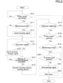
FIG. 2 is a view showing a sequential flow of the monitoring system in the working machine. -
FIG. 3 is a view showing a sequential flow of the monitoring system in a mobile terminal. -
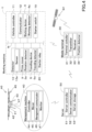
FIG. 4 is an overall view of a monitoring system for a working machine according to a modified example. -
FIG. 5 is a view showing a sequential flow of the monitoring system in a mobile terminal according to the modified example. -
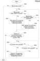
FIG. 6 is a view showing a sequential flow of the monitoring system in a server according to the modified example. - Hereinafter, an embodiment of the present invention will be described with appropriate reference to the drawings.
-
FIG. 1 is an overall view of a monitoring system for a working machine 1. The monitoring system for the working machine 1 is a system for monitoring the working machine 1. The monitoring system for the working machine 1 can reduce the possibility of the theft of the working machine 1, intrusion of suspicious persons, and the like, by periodically or randomly dispatching a surveillance drone orother management machine 40 to the vicinity of the working machine 1. - The working machine 1 means agricultural machinery and the like which performs work including plowing and harvesting of crops in the field, and the agricultural machinery includes a tractor, a combine, a rice transplanter, and the like. The tractor 1, which is one of the agricultural machinery, will be used as an example for the following description. The tractor 1 can be provided with a
working device 4 such as, for example, a cultivator, a mower, a tedder, a rake, and the like. - First, the overall configuration of the tractor 1 will be described below.
- As shown in
FIG. 1 , the tractor 1 is provided with a traveling vehicle (traveling vehicle body) 7 having atraveling device 5, and a prime mover (driving portion) 3, such as a diesel engine. - The tractor 1 is provided with a vehicle controller (vehicle controller device) 11 and a communicator (communicator device) 12. The tractor 1 is also provided with a speed detector (speed detector portion) 3a, a working detector (working detector portion) 4a, a traveling detector (traveling detector portion) 5a, a
starter switch 19, and astarter relay 20. Theprime mover 3, theworking device 4, thetraveling device 5, thevehicle controller 11, thecommunicator 12, the boarding detector (boarding detector device) 13, the rotating-speed detector 3a, theworking detector 4a, thetraveling detector 5a, thestarter switch 19, and thestarter relay 20 are connected by an on-board network N such as CAN. In other words, the devices connected by the on-board network N, including theprime mover 3, theworking device 4, and thetraveling device 5, can output and acquire information among the devices on the on-board network N. For example, thevehicle controller 11 can obtain the number of revolutions of theprime mover 3 from the rotating-speed detector 3a. Thevehicle control device 11 can also obtain the vehicle speed of the travelingdevice 5 from thetraveling detector 5a. Thevehicle controller 11 can also acquire information such as the operating state of theworking device 4 from the workingdetector 4a. In particular, the rotating-speed detector 3a is a device that detects the number of revolutions of theprime mover 3. In other words, the rotating-speed detector 3a can detect whether theprime mover 3 is starting or not. The rotating-speed detector 3a is provided in theprime mover 3 and includes a sensor or the like that detects the number of revolutions of theprime mover 3. The rotating-speed detector 3a can be any type of sensor as long as it is capable of detecting whether theprime mover 3 is starting or not. The rotating-speed detector 3a can output a signal based on the number of revolutions detected by the rotating-speed detector 3a to thevehicle controller 11 via the on-board network N. In other words, thevehicle controller 11 can obtain the number of revolutions of theprime mover 3 from the rotating-speed detector 3a. - The working
detector 4a is a device for detecting a state of an actuator and the like provided in theworking device 4. In detail, theworking detector 4a detects, for example, the number of rotations of the actuator provided in theworking device 4, the rotational speed of the actuator, and the like. In other words, the workingdetector 4a can detect whether theworking device 4 is operating or not. The workingdetector 4a is provided in theworking device 4 and includes a sensor or the like that detects the number of rotations of the actuator, the rotational speed of the actuator, and the like. The workingdetector 4a can be any type of workingdetector 4a that can detect whether theworking device 4 is operating or not. The workingdetector 4a can output a signal based on the information detected by the workingdetector 4a to thevehicle controller 11 via the on-board network N. The workingdetector 4a can also output a signal based on the information detected by theworking detector 4a to thevehicle controller 11. In other words, thevehicle controller 11 can obtain the status of theworking device 4 from the workingdetector 4a. - The
traveling detector 5a is a device that detects the traveling speed (ground speed) of the working machine 1, that is, the speed of thetraveling device 5. In other words, thetraveling detector 5a can detect whether thetraveling device 5 is operating or not. Thetraveling detector 5a is provided in thetraveling device 5 and includes a speed sensor or the like that detects the vehicle speed of the working machine 1. The travelingdetector 5a can be any type of device that is capable of detecting whether thetraveling device 5 is operating or not. - The
vehicle controller 11 includes a CPU or the like and performs various controls relating to the working machine 1. - The
communicator 12 is a device that communicates, for example, with thetransmitter 32 andreceiver 33 provided in themobile terminal 30. Thecommunicator 12 is a device that communicates over a short or long distance. For example, thecommunicator 12 performs the wireless communication with thereceiver 33 in a wireless fidelity (wireless fidelity, a registered trademark) in the IEEE802.11 series of communication standards, Bluetooth (a registered trademark) Low Energy in the specifications of the Bluetooth (registered trademark) in the IEEE802.15.1 series of communication standards, and the like. - The
starter switch 19 is a switch for starting theprime mover 3. When an operator inserts an engine key into a key cylinder provided around the operator seat and turns the engine key, thestarter switch 19 outputs a signal to thestarter relay 20 to start the prime mover. - The
starter relay 20 is a component for starting theprime mover 3. When a signal for starting the prime mover is input from thestarter switch 19 to thestarter relay 20, thestarter relay 20 starts theprime mover 3. The starting of the prime mover, which is one of the prime mover drives, is not limited to a mechanical type (key cylinder type) where the engine key is inserted into the key cylinder and thestarter relay 20 is turned on, but may be a smart entry type where the starting of the prime mover is permitted or prohibited by radio communication. - The
mobile terminal 30 includes, for example, a PC or a smartphone (multifunctional mobile phone) with relatively high computing power. Themobile terminal 30 includes a terminal controller (terminal controller device) 31, a transmitter (transmitter portion) 32, a receiver (receiver portion) 33, a position detector (position detector device) 34. - The
terminal controller 31 includes a CPU or the like and performs various controls relating to themobile terminal 30. Thetransmitter 32 transmits position information detected by theposition detector 34 to the working machine 1, themanagement machine 40 and the like. Thetransmitter 32 carries out wireless communication with the working machine 1, themanagement machine 40, and the like by, for example, Wi-Fi (registered trademark). Thetransmitter 32 may also communicate wirelessly with the working machine 1, themanagement machine 40, and the like by means of a data communication network, a cellular phone communication network, Bluetooth (registered trademark) Low Energy, or the like. - The
receiver 33 receives signals from thecommunicator 12. Thereceiver 33 carries out wireless communication with the working machine 1, themanagement machine 40 and the like by, for example, Wi-Fi (registered trademark) or the like. Thereceiver 33 may also perform wireless communication with the working machine 1, themanagement machine 40, and the like by means of a data communication network, a cellular phone communication network, Bluetooth (registered trademark) Low Energy, and the like. - The
position detector 34 is a device that detects its own position (positioning information) by a satellite positioning system. Theposition detector 34 receives a signal transmitted from the positioning satellite G1 and detects its own position (for example, latitude and longitude) based on the received signal. In other words, an operator working in the field can detect the position of the working machine 1 by having themobile terminal 30 in his or her possession at the time of work. This allows the monitoring system for the working machine 1 to use themobile terminal 30, which is pre-installed with theposition detector 34. Thus, the monitoring system for the working machine 1 can be easily introduced even if the working machine 1 does not have aposition detector 34. Themobile terminal 30 can also communicate with theserver 50 by means of a data communication network or a cellular phone communication network. Thus, even if thecommunicator 12 provided in the working machine 1 supports only short-range communication, the working machine 1 can communicate with theserver 50 via themobile terminal 30. In other words, theserver 50 can call themanagement machine 40. - As shown in
FIG. 1 , themanagement machine 40 is a rotor craft capable of flying unmanned by a plurality ofrotor blades 45, for example, a flying vehicle called a multicopter (drone). In other words, themanagement machine 40 is a multicopter capable of flying over a field. This allows themanagement machine 40 to be easily dispatched even when it is difficult to move over the ground, such as when the surface of the field on which the working machine 1 is working is rough. As a result, themanagement machine 40 can be dispatched regardless of the condition of the field, and the possibility of the theft of the working machine 1 can be reduced in advance. Themanagement machine 40 is capable of flying by autonomous control without relying on a remote device. Themanagement machine 40 may not be a flying machine, but may have a mobile means such as a crawler that moves on the ground. In other words, since themanagement machine 40 is used to monitor the working machine 1, there is no need to install a device for monitoring the working machine 1 itself. Thus, in the future, themanagement machine 40 with improved monitoring capability, that is, a monitoring system with high monitoring capability, can be easily introduced. - The
management machine 40 has amain body 41, anarm 42, arotor blade 45 and askid 43. - As shown in
FIG. 1 , a plurality ofarms 42 are attached to themain body 41. In the case of the present embodiment, sixarms 42 are attached to themain body 41; the sixarms 42 extend radially from the center of themain body 41 in a horizontal plane (a plane parallel to the ground in a landing state). However, the number ofarms 42 is not limited to six, but may be seven or more, or five or less. Thearm 42 may be foldable toward themain body 41. The base end side of thearms 42 is attached to themain body 41. Each of the plurality ofarms 42 has arotator blade 45 attached to the tip side of the plurality ofarms 42. - The
rotor blades 45 generate lift force for themanagement machine 40 to fly. Therotor blade 45 includes a rotor and a blade (propeller). The rotor includes an electric motor (such as a DC motor). The rotor is driven by power supplied from a battery. A blade is attached to the upper part of the rotor's axis of rotation. The adjacentrotating blades 45 rotate in opposite directions to each other. - The number of
rotor blades 45 is not limited and can be changed according to the required lift and other requirements. For example, themanagement machine 40 may be a tricopter having threerotor blades 45, a quadcopter having fourrotor blades 45, a hexacopter having sixrotor blades 45, or an octocopter having eightrotor blades 45. In the following description, therotor blades 45 may also be referred to as the movingportion 45. - The
skid 43 is installed when themanagement machine 40 lands and supports themain body 41 on the ground. - The
management machine 40 also has acontroller device 44, the movingportion 45, amanagement communicator 46, and amonitor 47. - The
controller device 44 includes a CPU and the like and performs various controls relating to themanagement machine 40. In particular, for example, thecontroller device 44 controls the movingportion 45. - The
management communicator 46 is a device by which themanagement machine 40 communicates wirelessly with thetransmitter 32 provided in themobile terminal 30, the outside, and the like. - The monitor portion (monitor device) 47 is a device for monitoring and monitoring a suspicious person approaching a worker or for reducing the possibility of theft or the like. In particular, it is a camera that captures images of the intruders and the like. The camera for capturing the intruders and the like can be a camera that takes still images, a video camera that takes moving images, or a similar type of camera. The image or video captured by the
monitor 47 is transmitted from themanagement communicator 46 to themobile terminal 30 or to the outside. Themonitor portion 47 may also be provided with a warning portion. The warning portion is an alarm that warns by means of a warning sound when, for example, themanagement machine 40 detects a suspicious person or theft of the working machine 1. The warning portion is not limited to an alarm that warns with a warning sound, but may also be one that warns with a light. Themonitor portion 47 can be anything that can reduce the possibility of the theft or the like of the working machine 1, as long as it can reduce the possibility of the theft or the like of the working machine 1 before it occurs, and it can be anything that prevents the theft. For example, themonitor portion 47 may be a dummy camera or the like disguised as a camera. - Now, the
vehicle controller 11 can be switched between a normal mode and a monitoring mode. The normal mode is a mode in which the operator boards the working machine 1 and performs the working in the field. On the other hand, the monitoring mode is a mode for monitoring the working machine 1 when the operator is not on board the working machine 1 and the working machine 1 is stopped. In detail, the normal mode and the monitoring mode are switched between the normal mode and the monitoring mode by means of a switching member installed around the operator seat of the working machine 1. The switching material is, for example, a switch such as a seesaw type switch or a push button switch. Thevehicle controller 11 switches between a normal mode and a monitoring mode based on a switching signal, which is a signal input from the switching member. Thevehicle controller 11 also determines whether theprime mover 3 of the working machine 1 is operating or not. In detail, thevehicle controller 11 determines whether theprime mover 3 of the working machine 1 is operating based on a signal input from thestarter switch 19. Thevehicle controller 11 may determine whether theprime mover 3 of the working machine 1 is operating based on a signal input from the rotating-speed detector 3a. - The tractor 1 is provided with the
boarding detector 13. Theboarding detector 13 is a device for detecting the boarding and alighting of an operator on the working machine 1. In particular, theboarding detector 13 detects an operator's boarding and alighting of the operator on the working machine 1 based on a signal output from the detection sensor. The detection sensor has asensor 13a, such as a pressure sensor, a strain sensor, or the like, installed in the seat of the operator seat 8 of the working machine 1. Thesensor 13a detects a load with respect to the seat of the operator seat 8 of the working machine 1. In detail, the presence or absence of an operator on the operator seat is detected by a signal output from thesensors 13a when an operator is seated in the operator seat 8 of the working machine 1 and when the operator is not seated in the operator seat 8. In this embodiment, the detection sensors include thesensor 13a, the rotating-speed detector 3a, the workingdetector 4a, and the travelingdetector 5a. In other words, theboarding detector 13 detects the boarding and alighting of the operator depending on whether the operator is seated in the operator seat 8 and whether theprime mover 3, the workingdevice 4, and the travelingdevice 5 are operating. The signals output from the rotating-speed detector 3a, the workingdetector 4a, and the travelingdetector 5a are output to theboarding detector 13 via the on-board network N. The signal output from theboarding detector 13 is output to thecommunicator 12. Theboarding detector 13 is not limited to the above configuration, and can be any device that can detect an operator's boarding and alighting to the working machine 1. For example, theboarding detector 13 may detect a change in load on the traveling vehicle body of the working machine 1 to detect the operator's boarding and alighting of the operator on the working machine 1. The detection sensor may include only at least one of thesensors 13a, such as the rotating-speed detector 3a, the workingdetector 4a, a travelingdetector 5a, a pressure sensor, and the like. In this case, theboarding detector 13 detects an operator's boarding and alighting of the operator on the working machine 1 based on a signal output from at least one of thesensors 13a, such as the rotating-speed detector 3a, the workingdetector 4a, the travelingdetector 5a, the pressure sensor, and the like. In particular, when the rotating-speed detector 3a detects the operation of theprime mover 3, it is determined that the operator is riding. When theoperation detection unit 4a detects the operation of the workingdevice 4, it is judged that the operator is in the vehicle. If the travelingdetector 5a detects the movement of the driving device, it is assumed that the operator is in the vehicle. If thesensor 13a detects that the operator is seated in the operator seat 8, it is determined that the operator is in the vehicle. That is, if a signal output from one of thesensors 13a, such as the rotating-speed detector 3a, the workingdetector 4a, the travelingdetector 5a, the pressure sensor, or the like, indicates that the operator is in the cab, thepassenger detection unit 13 detects that the operator is in the cab. On the other hand, if thespeed detection section 3a detects the stop of theprime mover 3, the workingdetector 4a detects the stop of the workingdevice 4, the travelingdetector 5a detects the stop of the travel device, and thesensor 13a detects that the operator is not seated in the operator seat 8, theboarding detector 13 detects the operator's alighting. - The
communicator 12 transmits to thereceiver 33, for example, a boarding signal indicating a boarding and a alighting signal indicating a boarding signal and an alighting signal indicating a boarding of the operator to the working machine 1 detected by theboarding detector 13. In particular, when theboarding detector 13 detects an operator boarding the working machine 1, thecommunicator 12 obtains a boarding signal from theboarding detector 13. Thecommunicator 12 transmits the boarding signal to thereceiver 33. On the other hand, when theboarding detector 13 detects the operator's alighting from the working machine 1, thecommunicator 12 obtains a alighting signal from theboarding detector 13. Thecommunicator 12 transmits the alighting signal to thereceiver 33. Thecommunicator 12 also transmits a parking signal to thereceiver 33, which notifies thereceiver 33 that the working machine 1 has stopped. When theprime mover 3 stops, thevehicle controller 11 determines that the working machine 1 has stopped after a predetermined time has elapsed and sends a parking signal. This allows the monitoring to be started in conjunction with the operator's alighting from the working machine 1. As a result, it is possible to reduce unprotected conditions such as stopping the working machine 1 and not being monitored even though the operator is not on board the working machine 1, or wasteful conditions such as monitoring even though the operator is on board the working machine 1 and the working is in progress. It is also possible to determine the operator's alighting based on the fact that the operator has completed the work and stopped theprime mover 3, the workingdevice 4, and the travelingdevice 5 of the working machine 1. For this reason, the system can determine the operator's alighting in a configuration that is also provided in the conventional work machine 1. In other words, it is easy to introduce a monitoring system for working machine 1. The system can also detect the seating of the operator in the seat of the operator seat 8 provided in the working machine 1. Thus, the presence or absence of an operator in the operator seat 8 of the working machine 1 can be easily determined. In other words, the accuracy of detecting the alighting and boarding of the operator can be improved. - The
terminal controller 31 can be switched between a normal mode and a monitoring mode. The normal mode is a mode for using normal PC and smartphone functions. The monitoring mode is a mode for calling themanagement machine 40 at regular intervals or randomly around the working machine. The switching between the normal mode and the monitoring mode is switched based on a terminal change signal received by thereceiver 33. In particular, when thereceiver 33 receives a terminal change signal, the mode is switched to either the normal mode or the monitoring mode based on the terminal change signal. If thereceiver 33 does not receive the terminal change signal, the current mode is maintained. - The
transmitter 32 transmits, for example, a call signal to themanagement machine 40. The call signal is a signal that includes positional information and a statement that the machine is to be dispatched to a position corresponding to the positional information. In other words, the call signal is a signal for calling themanagement machine 40 to the vicinity of the work machine. Thetransmitter 32 transmits the call signal to themanagement machine 40 at predetermined time intervals or at random time intervals. This eliminates the need to have themanagement machine 40 always on standby in the vicinity of the working machine. It also reduces the possibility that themanagement machine 40 will be dispatched and the time interval to be monitored is known. In other words, the possibility that themanagement machine 40 is not dispatched in the vicinity of the working machine and that the working machine 1 is targeted during the interval of monitoring can be reduced. - The
receiver 33 receives, for example, a parking signal and a boarding signal. The received stop and boarding signals are output to theterminal controller 31. - The
controller device 44 moves themanagement machine 40 based on the call signal received by themanagement communicator 46. In detail, the call signals are transmitted from thetransmitter 32 when theterminal controller 31 of themobile terminal 30 is in the monitoring mode. Theterminal controller 31 is in the monitoring mode when thevehicle controller 11 of the working machine 1 is in the monitoring mode, for example, when theboarding detector 13 detects an operator's alighting. In other words, thecontroller device 44 can move themanagement machine 40 to the relevant position based on the position information detected by theposition detector 34 when theboarding detector 13 detects an operator's alighting. - The
management communicator 46 receives a call signal from thetransmitter 32. Themanagement communicator 46 performs wireless communication with thetransmitter 32 and the outside and the like by means of Wi-Fi (registered trademark) and the like. Themanagement communicator 46 receives signals from thetransmitter 32 and the outside world, for example, by means of a cellular phone communication network, a data communication network, a cellular phone communication network, or the like. Themanagement communicator 46 receives, for example, a call signal from thetransmitter 32 or the outside world. The call signal received by themanagement communicator 46 is output to thecontroller device 44. - A series of operations of the monitoring system in the working machine 1 will be described below, with reference to
FIG. 2 . - The
vehicle controller 11 determines whether theprime mover 3 of the working machine 1 is operating (step S10). In detail, thevehicle controller 11 determines whether theprime mover 3 of the working machine 1 is started or not based on a signal input from thestarter switch 19. - If the
vehicle controller 11 determines that theprime mover 3 is operating, thevehicle controller 11 confirms whether thevehicle controller 11 is in the normal mode or the monitoring mode (step S11). - When the
vehicle controller 11 is in the monitoring mode, thecommunicator 12 transmits a boarding signal to thereceiver 33 of the mobile terminal 30 (step S12). - The
vehicle controller 11 checks whether the operation signal is output from theoperation member 10 provided around the operator seat to the vehicle controller 11 (step S13). In other words, thevehicle controller 11 confirms whether theoperation member 10 is being operated. - When the
vehicle controller 11 confirms that an operation signal is output from theoperation member 10 to thevehicle controller 11, thevehicle controller 11 confirms whether there is a change in the mode setting of the vehicle controller 11 (step S14). In particular described, thevehicle controller 11 confirms whether there is a change from one of the normal mode or the monitoring mode to the other. In detail, the signal output from the switching section material is acquired. In other words, thevehicle controller 11 determines that there is a change in the setting when the switching signal is output from the switching component material to thevehicle controller 11. On the other hand, thevehicle controller 11 determines that there is no setting change if no switching signal is output from the switching component to thevehicle controller 11. - When the
vehicle controller 11 confirms that there is a setting change from either the normal mode or the monitoring mode, thevehicle controller 11 sends a terminal change signal (step S15). In particular, in this case, thecommunicator 12 transmits the terminal change signal to thereceiver 33 of themobile terminal 30. - On the other hand, if the
vehicle controller 11 determines that there is no change in the setting from either the normal mode or the monitoring mode, thevehicle controller 11 controls the workingdevice 4 and the travelingdevice 5 based on the operation of the operation member 10 (step S16). In particular, thevehicle controller 11 controls the workingdevice 4 and the travelingdevice 5 based on the signal input to thevehicle controller 11 from theoperation member 10. - The
boarding detector 13 checks whether the operator is alighting (step S17). In particular, if a signal output from one of thesensors 13a, such as the rotating-speed detector 3a, the workingdetector 4a, the travelingdetector 5a, the pressure sensor, or the like, indicates that the operator is on board, theboarding detector 13 detects that the operator is on board. On the other hand, theboarding detector 13 detects the operator's alighting when either theprime mover 3 is stopped, the workingdevice 4 is stopped, the traveling device is stopped, or the operator is not seated. - The
vehicle controller 11 determines whether theprime mover 3 of the working machine 1 is not operating (step S18). In detail, thevehicle controller 11 determines whether or not theprime mover 3 of the working machine 1 has been started based on the signal input from thestarter switch 19. - If the
vehicle controller 11 determines that theprime mover 3 of the working machine 1 is not operating, thevehicle controller 11 confirms whether thevehicle controller 11 is in the normal mode or the monitoring mode (step S19). - After a predetermined time (step S20), the
communicator 12 transmits a parking signal to thereceiver 33 of the mobile terminal 30 (step S21). - After sending the parking signal, the working machine 1 shuts down (step S22). In other words, the system inside the working machine 1, including the
vehicle controller 11 of the working machine 1, is shut down. - A series of operations of the monitoring system at the
mobile terminal 30 will be described below, with reference toFIG. 3 . - The
terminal control device 31 determines whether or not it is in the monitoring mode (step S30). In particular, theterminal controller 31 checks whether thereceiver 33 receives a terminal change signal. If a terminal change signal is received, theterminal controller 31 determines that theterminal controller 31 has been changed from one of the normal mode and the monitoring mode to the other. If the terminal change signal is not received, theterminal controller 31 maintains the current mode. - If it is determined to be in the monitoring mode, the
terminal controller 31 confirms whether thereceiver 33 is receiving the parking signal (step S31). - If it is confirmed that the parking signal is being received, the
boarding detector device 13 detects the positional information (step S32). In particular, theposition detector 34 receives the signal transmitted from the positioning satellite G1 and detects its own position based on the received signal. In other words, theposition detector 34 detects the position of the operator at the time of boarding or alighting from the working machine 1. - The
terminal control device 31 sets up monitoring by themanagement machine 40 for the position detected by the boarding detector 13 (step S33). - On the other hand, if the parking signal is not received, the
terminal controller 31 checks whether thereceiver 33 receives the boarding signal (step S34). - If it is determined that the boarding signal is being received, the
terminal controller 31 releases the monitoring at the position detected by the positional information detector (step S35). In detail, theterminal controller 31 releases the setting of the monitoring when the monitoring is set for the position. On the other hand, theterminal controller 31 does not set the monitoring for the position if the monitoring is not set for the position. - It checks whether monitoring is set for the location where the positional information is detected (step S36).
- After a certain amount of time has passed (step S37), the
mobile terminal 30 dispatches themanagement machine 40 about the location where the positional information was detected (step S38). In particular, thetransmitter 32 of themobile terminal 30 transmits a call signal including the positional information detected by theposition detector device 34 to themanagement machine 40. Thereby, based on the call signal, themanagement machine 40 moves to the position. In other words, themobile terminal 30 dispatches themanagement machine 40 to the vicinity of the work machine at regular intervals. - Even before a certain amount of time has elapsed (step S37), if a random amount of time has elapsed (step S39), the
management machine 40 is dispatched to the location where theposition detector device 34 has detected the positional information (step S38). In particular, thetransmitter 32 of themobile terminal 30 transmits a call signal including the positional information detected by theposition detector device 34 to themanagement machine 40. Thereby, based on the call signal, themanagement machine 40 moves to the position. In other words, themobile terminal 30 dispatches themanagement machine 40 to the vicinity of the work machine at random time intervals. - The monitoring system for the working machine 1 according to one aspect of the present invention is provided with a
boarding detector 13, aposition detector 34, acommunicator 12, and acontrol device 44. This allows the monitoring to be initiated in conjunction with the operator's alighting from the working machine 1. As a result, it is possible to reduce unprotected conditions such as stopping the working machine 1 and not being monitored even though the operator is not on board the working machine 1, or wasteful conditions such as monitoring even though the operator is on board the working machine 1 and the work is in progress. In addition, since themanagement machine 40 is used to monitor the working machine 1, there is no need to install a device for monitoring the working machine 1 itself. Thus, in the future, amanagement machine 40 with improved monitoring capability, that is, a monitoring system with high monitoring capability, can be easily introduced. - The working machine 1 is provided with a detection sensor that detects the operation of at least one of the
prime mover 3 of the working machine 1, the workingdevice 4 of the working machine 1, and the travelingdevice 5 of the working machine 1, and theboarding detector 13 determines the alighting based on the signal output from the detection sensor. This allows the operator to determine the operator's alighting based on the fact that the operator has completed the work and stopped theprime mover 3, the workingdevice 4, and the travelingdevice 5 of the working machine 1. For this reason, the system can determine the operator's alighting in a configuration that is also provided in the conventional work machine 1. In other words, the monitoring system for the working machine 1 can be easily introduced. - The detection sensor includes the
sensor 13a that detects whether the operator is seated or not, and theboarding detector 13 determines the alighting based on the signal input from thesensor 13a. This enables the operator to detect the seating of the operator in the seat of the operator seat 8 provided in the working machine 1. Thus, the presence or absence of an operator in the operator seat 8 of the working machine 1 can be easily determined. In other words, the accuracy of detecting the alighting and boarding of the operator can be improved. - The monitoring system of the working machine 1 is provided with the
position detector 34 and themobile terminal 30, the working machine 1 has thecommunicator 12, and thetransmitter 32 of themobile terminal 30 transmits the position information detected by theposition detector 34 and the yield received by thereceiver 33 to themanagement machine 40. This allows the monitoring system for the working machine 1 to use themobile terminal 30, which has aposition detector 34 provided in advance. Thus, the monitoring system for the working machine 1 can be easily introduced even if the working machine 1 does not have theposition detector 34. Themobile terminal 30 can also communicate with theserver 50 by means of a data communication network or a cellular phone communication network. Thus, even if thecommunicator 12 provided in the working machine 1 supports only short-range communication, the working machine 1 can communicate with theserver 50 via themobile terminal 30. In other words, theserver 50 can call themanagement machine 40. - The
controller 44 moves themanagement machine 40 at every predetermined time interval or at random time intervals, based on the positional information. This also reduces the possibility that themanagement machine 40 will be dispatched and the time interval to be monitored is known. In other words, the possibility that themanagement machine 40 is not dispatched in the vicinity of the work machine and that the working machine 1 is targeted during the interval of monitoring can be reduced. - The
management machine 40 is a multicopter capable of flying over the field. This allows themanagement machine 40 to be easily dispatched even when it is difficult to move on the ground, such as when the road surface in the field where the working machine 1 is working is rough. As a result, themanagement machine 40 can be dispatched regardless of the field conditions, and the possibility of the theft of the working machine 1 can be reduced in advance. - Now, in the monitoring system for the working machine 1 described above, the
mobile terminal 30 calls themanagement machine 40, but theserver 50 may also call themanagement machine 40, as in the monitoring system for the working machine 1 shown inFIG. 4 . - The
server 50 has aserver controller device 51, aserver communicator device 52, and aserver storage 53. - The
server controller device 51 includes a CPU and the like, and performs various controls relating to theserver 50. - The
server communication device 52 enables theserver 50 to communicate wirelessly with themobile terminal 30 and themanagement machine 40. Theserver communication device 52, for example, communicates wirelessly with thetransmitter 32 and thereceiver 33 of themobile terminal 30 and themanagement communicator 46 of themanagement machine 40 by means of the IEEE 802.11 series Wi-Fi (registered trademark) or the like, which is a communication standard. Theserver communication device 52 may, for example, communicate wirelessly with thetransmitter 32, thereceiver 33, and themanagement communicator 46 by means of a cellular phone communication network, a data communication network, a cellular phone communication network, or the like. - The
server storage 53 is a non-volatile memory or the like, and stores various information, including information received by theserver communication device 52. - The
server controller device 51 can be switched between a normal mode and a monitoring mode. The normal mode is a mode in which the normal functions of theserver 50 are used. The monitoring mode is a mode for calling themanagement machine 40 at regular intervals or randomly around the work machine. The switching between the normal mode and the monitoring mode is switched based on a server change signal received by theserver communication device 52 from thetransmitter 32 of themobile terminal 30. In particular, when theserver communication device 52 receives a server change signal from thetransmitter 32, theserver communication device 52 switches to one of the normal mode and the monitoring mode based on the server change signal. If theserver communication device 52 does not receive a server change signal from thetransmitter 32, the current mode is maintained. - The
server communication device 52, for example, receives a server change signal from thetransmitter 32 of themobile terminal 30. Theserver communication device 52 also sends a call signal to themanagement communicator 46. In detail, theserver communication device 52 transmits a call signal to themanagement communicator 46 at predetermined or random time intervals. Theserver communication device 52 receives the images and videos captured by themonitor 47 from themanagement communicator 46. This allows the working machine 1 to dispatch themanagement machine 40 via themobile terminal 30 and theserver 50. Thus, even if the processing power of theterminal controller 31 of themobile terminal 30 is not very high, complex processing can be performed, such as dispatching a plurality ofmanagement machines 40. In addition to the monitoring system for the working machine 1 of the present invention, the system can be used in conjunction with other monitoring systems possessed by theserver 50. In other words, the monitoring capability of the monitoring system for the working machine 1 can be improved. - A series of operations of the monitoring system in the working machine 1 will be described below with reference to
FIG. 5 . - The
terminal controller 31 determines whether or not it is in the monitoring mode (step S130). In particular, theterminal controller 31 checks whether thereceiver 33 receives a terminal change signal. If a terminal change signal is received, theterminal controller 31 determines that theterminal controller 31 has been changed from one of the normal mode and the monitoring mode to the other. If the terminal change signal is not received, theterminal controller 31 maintains the current mode. - If the
terminal controller 31 determines that it is not in the monitoring mode, for example, it is in the normal mode, thetransmitter 32 transmits a server change signal to theserver communicator device 52, which instructs it to change to the normal mode (step S131). - On the other hand, if it determines that it is in the monitoring mode, the
transmitter 32 transmits a server change signal instructing the server to change to the monitoring mode (step S132). - If the
terminal control device 31 determines that it is in the monitoring mode, theterminal control device 31 confirms whether thereceiver 33 is receiving the parking signal (step S133). - If it is confirmed that the parking signal is received, the
boarding detector device 13 detects the positional information (step S134). In particular, theposition detector 34 receives the signal transmitted from the positioning satellite G1 and detects its own position based on the received signal. In other words, theposition detector 34 detects the position of the operator when the operator boards on or alters the working machine 1. - The
transmitter 32 transmits a monitoring start signal to theserver communication device 52 about the position detected by the boarding detector 13 (step S135). - On the other hand, if the parking signal is not received, the
terminal controller 31 checks whether thereceiver 33 is receiving the boarding signal (step S136). - If it is determined that the boarding signal is being received, the
transmitter 32 transmits a monitoring termination signal (step S137). In other words, theterminal controller 31 releases the monitoring at the relevant position detected by the positional information detector. In detail, when the monitoring is set for the position, theterminal controller 31 releases the setting of the monitoring by sending the monitoring termination signal to theserver communication device 52. On the other hand, theterminal controller 31 does not set the monitoring for the location by sending a monitoring termination signal to theserver communication device 52 when the monitoring is not set for the location. - A series of operations of the monitoring system at the
server 50 will be described below with reference toFIG. 6 . - The
server controller 51 determines whether or not it is a monitoring mode (step S50). In particular, theserver controller 51 checks whether thereceiver 33 receives a server change signal. If a server change signal is received, theserver controller 51 determines that the server has been changed from one of the normal mode and the monitoring mode to the other. If the server change signal is not received, theserver controller device 51 maintains the current mode. - If it is determined to be a monitoring mode, the
server controller 51 checks whether theserver communication device 52 receives a monitoring start signal from thetransmitter 32 of the mobile terminal 30 (step S51). - If the
server control device 51 confirms that it has received a monitoring start signal from thetransmitter 32, theserver control device 51 sets the monitoring mode for the position detected by the boarding detector device 13 (step S52). - On the other hand, if the monitoring start signal has not been received, the
server controller device 51 confirms whether or not a monitoring termination signal has been received from the transmitter 32 (step S53). - If it is determined that the monitoring termination signal is received, the
server controller device 51 releases the monitoring at the relevant position detected by the positional information detector (step S54). In detail, theserver controller 51 sets the monitoring mode if the monitoring is set for the position. On the other hand, theserver controller 51 releases the setting of the monitoring mode for the position if the monitoring is not set for the position. - The server checks whether monitoring is set up at the location where the positional information is detected (step S55).
- After a certain amount of time has passed (step S56), the
server 50 dispatches themanagement device 40 about the location where the positional information is detected (step S57). In particular, theserver communication device 52 sends a call signal including the positional information detected by theposition detector device 34 to themanagement machine 40. Thereby, based on the call signal, themanagement machine 40 moves to the location. In other words, themobile terminal 30 dispatches themanagement machine 40 to the vicinity of the work machine at regular intervals. - Even before a certain amount of time has passed (step S56), if a random amount of time has passed (step S58), the
server 50 dispatches themanagement machine 40 to the location where the positional information was detected (step S57). In particular, theserver communication device 52 sends a call signal including the positional information detected by theposition detector device 34 to themanagement machine 40. Thereby, based on the call signal, themanagement machine 40 moves to the location. In other words, theserver 50 dispatches themanagement machine 40 to the vicinity of the work machine at random time intervals. - The monitoring system for the working machine 1 as described above has a
server 50 that receives position information and demurrage from thetransmitter 32 and transmits the position information and demurrage to themanagement machine 40, and thetransmitter 32 of themobile terminal 30 transmits the position information detected by theposition detector 34 and the demurrage received by thereceiver 33 to themanagement machine 40 via theserver 50. This enables the working machine 1 to dispatch themanagement machine 40 via themobile terminal 30 and theserver 50. Thus, even if the processing capacity of theterminal controller 31 of themobile terminal 30 is not very high, it can perform complex processing, such as dispatching a plurality ofmanagement machines 40. In addition to the monitoring system for the working machine 1 of the present invention, the system can be used in combination with other monitoring systems possessed by theserver 50. In other words, the monitoring capability of the monitoring system for the working machine 1 can be improved. - In the above description, the embodiment of the present invention has been explained. However, all the features of the embodiment disclosed in this application should be considered just as examples, and the embodiment does not restrict the present invention accordingly. A scope of the present invention is shown not in the above-described embodiment but in claims.
-
- 1
- Working machine
- 3
- Prime mover
- 4
- Working device
- 5
- Traveling device
- 12
- Communicator device
- 13
- Boarding detector
- 13a
- Sensor
- 30
- Mobile terminal
- 32
- Transmitter
- 33
- Receiver
- 34
- Position detector
- 40
- Management machine
- 44
- Controller
- 45
- Mover (Rotor blade)
- 50
- Server
Claims (7)
- A monitoring system for a working machine (1), comprising:a boarding detector (13) to detect boarding and alighting of an operator, the boarding detector (13) being provided in the working machine (1);a position detector (34) to detect a position of the working machine (1) based on a signal sent from a positioning satellite (G1) when the boarding detector (13) detects the alighting of the operator, the position detector (34) being provided in a mobile terminal (30) belonging to the operator;a transmitter (32) to transmit, to a management machine (40), positional information representing the position detected by the position detector (34) , the transmitter (32) being provided in the mobile terminal (30); anda controller (44) to, based on the positional information received from the transmitter (32), move the management machine (40) to the position represented by the positional information, the controller (44) being provided in the management machine (40).
- The monitoring system for the working machine (1) according to claim 1, comprisinga detection sensor to detect movement of at least one of the following: a prime mover (3) included in the working machine (1), a working device (4) included in the working machine (1), and a traveling device (5) included in the working machine (1), whereinthe boarding detector (13) judges the alighting based on a signal output from the detection sensor.
- The monitoring system for the working machine (1) according to claim 1 or 2, wherein
the boarding detector (13) includes a sensor (13a) to detect whether the operator sits on and judges the alighting based on the signal output from the sensor (13a). - The monitoring system for the working machine (1) according to any one of claims 1 to 3, comprising:a communicator (12) to transmit an alighting signal indicating the alighting detected by the boarding detector (13), the communicator (12) being provided in the working machine (1); anda receiver (33) to receive the alighting signal from the communicator (12), the receiver (33) being provided in the mobile terminal (30),wherein the transmitter (32) transmits, to the management machine (40), the positional information detected by the position detector (34) and the alighting signal received by the receiver (33).
- The monitoring system for the working machine (1) according to claim 4, comprisingA server (50) to receive the positional information and the alighting signal from the transmitter (32) and to transmit the positional information and the alighting signal to the management machine (40), whereinthe transmitter (32) of the mobile terminal (30) transmits the positional information detected by the position detector (34) and the alighting signal received by the receiver (33) to the management machine (40) through the server (50).
- The monitoring system for the working machine (1) according to any one of claims 1 to 5, wherein
the controller (44) moves the management machine (40) based on the positional information at either a predetermined time interval or an arbitrary time interval. - The monitoring system for the working machine (1) according to any one of claims 1 to 6, wherein
the management machine (40) is a multicopter to fly over the agricultural field.
Applications Claiming Priority (2)
| Application Number | Priority Date | Filing Date | Title |
|---|---|---|---|
| JP2018075638A JP6973889B2 (en) | 2018-04-10 | 2018-04-10 | Work equipment monitoring system |
| PCT/JP2019/011457 WO2019198440A1 (en) | 2018-04-10 | 2019-03-19 | Monitoring system for work machine |
Publications (3)
| Publication Number | Publication Date |
|---|---|
| EP3779850A1 EP3779850A1 (en) | 2021-02-17 |
| EP3779850A4 EP3779850A4 (en) | 2022-01-12 |
| EP3779850B1 true EP3779850B1 (en) | 2025-03-19 |
Family
ID=68162863
Family Applications (1)
| Application Number | Title | Priority Date | Filing Date |
|---|---|---|---|
| EP19784920.1A Active EP3779850B1 (en) | 2018-04-10 | 2019-03-19 | Monitoring system for work machine |
Country Status (4)
| Country | Link |
|---|---|
| US (1) | US11872956B2 (en) |
| EP (1) | EP3779850B1 (en) |
| JP (1) | JP6973889B2 (en) |
| WO (1) | WO2019198440A1 (en) |
Families Citing this family (1)
| Publication number | Priority date | Publication date | Assignee | Title |
|---|---|---|---|---|
| JP7476661B2 (en) * | 2020-05-19 | 2024-05-01 | マツダ株式会社 | Vehicle Surroundings Monitoring System |
Family Cites Families (14)
| Publication number | Priority date | Publication date | Assignee | Title |
|---|---|---|---|---|
| JP4703057B2 (en) | 2001-08-16 | 2011-06-15 | 富士通テン株式会社 | Anti-theft device |
| WO2012125726A1 (en) | 2011-03-14 | 2012-09-20 | Intelligent Technologies International, Inc. | Cargo theft prevention system and method |
| US20060206246A1 (en) * | 2004-10-28 | 2006-09-14 | Walker Richard C | Second national / international management and security system for responsible global resourcing through technical management to brige cultural and economic desparity |
| US20140152016A1 (en) * | 2012-12-03 | 2014-06-05 | James Edward Jennings | Atmospheric transduction system |
| JP5996468B2 (en) * | 2013-03-28 | 2016-09-21 | 株式会社クボタ | Agricultural management support system |
| JP5972820B2 (en) * | 2013-03-29 | 2016-08-17 | 株式会社クボタ | Work management support device |
| US9253551B1 (en) * | 2014-09-15 | 2016-02-02 | Google Inc. | Methods, systems, and media for providing personalized notifications to video viewers |
| US10165722B2 (en) | 2014-12-05 | 2019-01-01 | Deere & Company | Scouting systems |
| US20170127606A1 (en) | 2015-11-10 | 2017-05-11 | Digi-Star, Llc | Agricultural Drone for Use in Controlling the Direction of Tillage and Applying Matter to a Field |
| KR20170059893A (en) * | 2015-11-20 | 2017-05-31 | 주식회사 드론메이트 | Drone comprising self camera |
| WO2017099070A1 (en) * | 2015-12-08 | 2017-06-15 | 住友重機械工業株式会社 | Shovel communication system, multicopter and shovel |
| JP6707984B2 (en) * | 2016-05-16 | 2020-06-10 | 井関農機株式会社 | Work vehicle control system |
| US10820034B2 (en) * | 2017-05-26 | 2020-10-27 | At&T Intellectual Property I, L.P. | Providing streaming video from mobile computing nodes |
| CN110998230B (en) * | 2017-08-01 | 2021-11-02 | 认为股份有限公司 | Driving systems for work machines |
-
2018
- 2018-04-10 JP JP2018075638A patent/JP6973889B2/en active Active
-
2019
- 2019-03-19 WO PCT/JP2019/011457 patent/WO2019198440A1/en not_active Ceased
- 2019-03-19 EP EP19784920.1A patent/EP3779850B1/en active Active
-
2020
- 2020-10-05 US US17/063,283 patent/US11872956B2/en active Active
Also Published As
| Publication number | Publication date |
|---|---|
| WO2019198440A1 (en) | 2019-10-17 |
| JP2019182211A (en) | 2019-10-24 |
| US11872956B2 (en) | 2024-01-16 |
| JP6973889B2 (en) | 2021-12-01 |
| EP3779850A1 (en) | 2021-02-17 |
| US20210016742A1 (en) | 2021-01-21 |
Similar Documents
| Publication | Publication Date | Title |
|---|---|---|
| US12045051B2 (en) | Remote monitoring system and an autonomous running vehicle and remote monitoring method | |
| US10388091B2 (en) | Vehicle remote control system and vehicle-mounted apparatus incorporated in the same | |
| EP3352040B1 (en) | Sensor management device and method for determining whether one or more obstacle sensors operate normally | |
| US9560692B2 (en) | Controlling a machine in remote or autonomous mode | |
| US11747831B2 (en) | Agricultural field management system, and agricultural field management method | |
| JP7026505B2 (en) | Worksite management system and worksite management method | |
| CN210822155U (en) | Far and near distance anti-theft alarm system of networked vehicle | |
| JP2021520547A (en) | Tracking stolen robot vehicles | |
| US12295277B2 (en) | Method and device for predicting potential accident of agricultural machine that performs autonomous driving and operates PTO, and controlling operation to avoid potential accident, in communication system | |
| US11954947B2 (en) | Monitoring system for working machine | |
| EP3779850B1 (en) | Monitoring system for work machine | |
| US20040181327A1 (en) | Vehicle security through an automatic control system | |
| US20250146254A1 (en) | Remote operation system of work machine and remote operation method for work machine | |
| US20250034841A1 (en) | Remote operation system of work machine and remote operationmethod for work machine | |
| KR102740147B1 (en) | Method And Apparatus for using an UAV in a vehicle | |
| US20250043544A1 (en) | Actual machine management device, and actual machine management system | |
| CN119816882A (en) | Mobile robot, server, mobile robot control system, and mobile robot control method | |
| US11679894B1 (en) | System and method for enabling the emergency remote override of a hijacked operation of a vehicle, a device or a facility | |
| CN111625014A (en) | Unmanned aerial vehicle control method, vehicle-mounted terminal and computer readable storage medium | |
| WO2020225681A1 (en) | Anti-hijacking system and method for an autonomous machine | |
| JP6602808B2 (en) | Autonomous traveling system for work vehicles | |
| US20240353850A1 (en) | Control device and remote support system | |
| US20250306896A1 (en) | Vehicle control system and vehicle control method | |
| JP4934315B2 (en) | Monitoring system, mobile robot and control device constituting the system | |
| JP2021115880A (en) | Drone |
Legal Events
| Date | Code | Title | Description |
|---|---|---|---|
| STAA | Information on the status of an ep patent application or granted ep patent |
Free format text: STATUS: THE INTERNATIONAL PUBLICATION HAS BEEN MADE |
|
| PUAI | Public reference made under article 153(3) epc to a published international application that has entered the european phase |
Free format text: ORIGINAL CODE: 0009012 |
|
| STAA | Information on the status of an ep patent application or granted ep patent |
Free format text: STATUS: REQUEST FOR EXAMINATION WAS MADE |
|
| 17P | Request for examination filed |
Effective date: 20201008 |
|
| AK | Designated contracting states |
Kind code of ref document: A1 Designated state(s): AL AT BE BG CH CY CZ DE DK EE ES FI FR GB GR HR HU IE IS IT LI LT LU LV MC MK MT NL NO PL PT RO RS SE SI SK SM TR |
|
| AX | Request for extension of the european patent |
Extension state: BA ME |
|
| DAV | Request for validation of the european patent (deleted) | ||
| DAX | Request for extension of the european patent (deleted) | ||
| A4 | Supplementary search report drawn up and despatched |
Effective date: 20211210 |
|
| RIC1 | Information provided on ipc code assigned before grant |
Ipc: B64C 39/02 20060101ALI20211206BHEP Ipc: B64C 13/18 20060101ALI20211206BHEP Ipc: B60R 25/33 20130101ALI20211206BHEP Ipc: B60R 25/31 20130101ALI20211206BHEP Ipc: G06Q 50/02 20120101AFI20211206BHEP |
|
| GRAP | Despatch of communication of intention to grant a patent |
Free format text: ORIGINAL CODE: EPIDOSNIGR1 |
|
| STAA | Information on the status of an ep patent application or granted ep patent |
Free format text: STATUS: GRANT OF PATENT IS INTENDED |
|
| INTG | Intention to grant announced |
Effective date: 20241128 |
|
| GRAS | Grant fee paid |
Free format text: ORIGINAL CODE: EPIDOSNIGR3 |
|
| GRAA | (expected) grant |
Free format text: ORIGINAL CODE: 0009210 |
|
| STAA | Information on the status of an ep patent application or granted ep patent |
Free format text: STATUS: THE PATENT HAS BEEN GRANTED |
|
| AK | Designated contracting states |
Kind code of ref document: B1 Designated state(s): AL AT BE BG CH CY CZ DE DK EE ES FI FR GB GR HR HU IE IS IT LI LT LU LV MC MK MT NL NO PL PT RO RS SE SI SK SM TR |
|
| REG | Reference to a national code |
Ref country code: GB Ref legal event code: FG4D |
|
| REG | Reference to a national code |
Ref country code: CH Ref legal event code: EP |
|
| REG | Reference to a national code |
Ref country code: IE Ref legal event code: FG4D |
|
| REG | Reference to a national code |
Ref country code: DE Ref legal event code: R096 Ref document number: 602019067510 Country of ref document: DE |
|
| PG25 | Lapsed in a contracting state [announced via postgrant information from national office to epo] |
Ref country code: RS Free format text: LAPSE BECAUSE OF FAILURE TO SUBMIT A TRANSLATION OF THE DESCRIPTION OR TO PAY THE FEE WITHIN THE PRESCRIBED TIME-LIMIT Effective date: 20250619 |
|
| PG25 | Lapsed in a contracting state [announced via postgrant information from national office to epo] |
Ref country code: FI Free format text: LAPSE BECAUSE OF FAILURE TO SUBMIT A TRANSLATION OF THE DESCRIPTION OR TO PAY THE FEE WITHIN THE PRESCRIBED TIME-LIMIT Effective date: 20250319 |
|
| REG | Reference to a national code |
Ref country code: LT Ref legal event code: MG9D |
|
| PG25 | Lapsed in a contracting state [announced via postgrant information from national office to epo] |
Ref country code: NO Free format text: LAPSE BECAUSE OF FAILURE TO SUBMIT A TRANSLATION OF THE DESCRIPTION OR TO PAY THE FEE WITHIN THE PRESCRIBED TIME-LIMIT Effective date: 20250619 |
|
| PG25 | Lapsed in a contracting state [announced via postgrant information from national office to epo] |
Ref country code: HR Free format text: LAPSE BECAUSE OF FAILURE TO SUBMIT A TRANSLATION OF THE DESCRIPTION OR TO PAY THE FEE WITHIN THE PRESCRIBED TIME-LIMIT Effective date: 20250319 |
|
| PG25 | Lapsed in a contracting state [announced via postgrant information from national office to epo] |
Ref country code: LV Free format text: LAPSE BECAUSE OF FAILURE TO SUBMIT A TRANSLATION OF THE DESCRIPTION OR TO PAY THE FEE WITHIN THE PRESCRIBED TIME-LIMIT Effective date: 20250319 |
|
| PG25 | Lapsed in a contracting state [announced via postgrant information from national office to epo] |
Ref country code: BG Free format text: LAPSE BECAUSE OF FAILURE TO SUBMIT A TRANSLATION OF THE DESCRIPTION OR TO PAY THE FEE WITHIN THE PRESCRIBED TIME-LIMIT Effective date: 20250319 Ref country code: GR Free format text: LAPSE BECAUSE OF FAILURE TO SUBMIT A TRANSLATION OF THE DESCRIPTION OR TO PAY THE FEE WITHIN THE PRESCRIBED TIME-LIMIT Effective date: 20250620 |
|
| REG | Reference to a national code |
Ref country code: NL Ref legal event code: MP Effective date: 20250319 |
|
| REG | Reference to a national code |
Ref country code: AT Ref legal event code: MK05 Ref document number: 1777579 Country of ref document: AT Kind code of ref document: T Effective date: 20250319 |
|
| PG25 | Lapsed in a contracting state [announced via postgrant information from national office to epo] |
Ref country code: NL Free format text: LAPSE BECAUSE OF FAILURE TO SUBMIT A TRANSLATION OF THE DESCRIPTION OR TO PAY THE FEE WITHIN THE PRESCRIBED TIME-LIMIT Effective date: 20250319 |
|
| PG25 | Lapsed in a contracting state [announced via postgrant information from national office to epo] |
Ref country code: SE Free format text: LAPSE BECAUSE OF FAILURE TO SUBMIT A TRANSLATION OF THE DESCRIPTION OR TO PAY THE FEE WITHIN THE PRESCRIBED TIME-LIMIT Effective date: 20250319 |
|
| PG25 | Lapsed in a contracting state [announced via postgrant information from national office to epo] |
Ref country code: SM Free format text: LAPSE BECAUSE OF FAILURE TO SUBMIT A TRANSLATION OF THE DESCRIPTION OR TO PAY THE FEE WITHIN THE PRESCRIBED TIME-LIMIT Effective date: 20250319 |
|
| PG25 | Lapsed in a contracting state [announced via postgrant information from national office to epo] |
Ref country code: ES Free format text: LAPSE BECAUSE OF FAILURE TO SUBMIT A TRANSLATION OF THE DESCRIPTION OR TO PAY THE FEE WITHIN THE PRESCRIBED TIME-LIMIT Effective date: 20250319 Ref country code: PT Free format text: LAPSE BECAUSE OF FAILURE TO SUBMIT A TRANSLATION OF THE DESCRIPTION OR TO PAY THE FEE WITHIN THE PRESCRIBED TIME-LIMIT Effective date: 20250721 |
|
| PG25 | Lapsed in a contracting state [announced via postgrant information from national office to epo] |
Ref country code: IT Free format text: LAPSE BECAUSE OF FAILURE TO SUBMIT A TRANSLATION OF THE DESCRIPTION OR TO PAY THE FEE WITHIN THE PRESCRIBED TIME-LIMIT Effective date: 20250319 Ref country code: PL Free format text: LAPSE BECAUSE OF FAILURE TO SUBMIT A TRANSLATION OF THE DESCRIPTION OR TO PAY THE FEE WITHIN THE PRESCRIBED TIME-LIMIT Effective date: 20250319 |
|
| PG25 | Lapsed in a contracting state [announced via postgrant information from national office to epo] |
Ref country code: AT Free format text: LAPSE BECAUSE OF FAILURE TO SUBMIT A TRANSLATION OF THE DESCRIPTION OR TO PAY THE FEE WITHIN THE PRESCRIBED TIME-LIMIT Effective date: 20250319 |
|
| PG25 | Lapsed in a contracting state [announced via postgrant information from national office to epo] |
Ref country code: EE Free format text: LAPSE BECAUSE OF FAILURE TO SUBMIT A TRANSLATION OF THE DESCRIPTION OR TO PAY THE FEE WITHIN THE PRESCRIBED TIME-LIMIT Effective date: 20250319 Ref country code: CZ Free format text: LAPSE BECAUSE OF FAILURE TO SUBMIT A TRANSLATION OF THE DESCRIPTION OR TO PAY THE FEE WITHIN THE PRESCRIBED TIME-LIMIT Effective date: 20250319 |
|
| REG | Reference to a national code |
Ref country code: CH Ref legal event code: H13 Free format text: ST27 STATUS EVENT CODE: U-0-0-H10-H13 (AS PROVIDED BY THE NATIONAL OFFICE) Effective date: 20251023 |
|
| PG25 | Lapsed in a contracting state [announced via postgrant information from national office to epo] |
Ref country code: RO Free format text: LAPSE BECAUSE OF FAILURE TO SUBMIT A TRANSLATION OF THE DESCRIPTION OR TO PAY THE FEE WITHIN THE PRESCRIBED TIME-LIMIT Effective date: 20250319 |
|
| PG25 | Lapsed in a contracting state [announced via postgrant information from national office to epo] |
Ref country code: SK Free format text: LAPSE BECAUSE OF FAILURE TO SUBMIT A TRANSLATION OF THE DESCRIPTION OR TO PAY THE FEE WITHIN THE PRESCRIBED TIME-LIMIT Effective date: 20250319 |
|
| PG25 | Lapsed in a contracting state [announced via postgrant information from national office to epo] |
Ref country code: IS Free format text: LAPSE BECAUSE OF FAILURE TO SUBMIT A TRANSLATION OF THE DESCRIPTION OR TO PAY THE FEE WITHIN THE PRESCRIBED TIME-LIMIT Effective date: 20250719 |
|
| PG25 | Lapsed in a contracting state [announced via postgrant information from national office to epo] |
Ref country code: LU Free format text: LAPSE BECAUSE OF NON-PAYMENT OF DUE FEES Effective date: 20250319 |
|
| REG | Reference to a national code |
Ref country code: BE Ref legal event code: MM Effective date: 20250331 |
|
| PG25 | Lapsed in a contracting state [announced via postgrant information from national office to epo] |
Ref country code: MC Free format text: LAPSE BECAUSE OF FAILURE TO SUBMIT A TRANSLATION OF THE DESCRIPTION OR TO PAY THE FEE WITHIN THE PRESCRIBED TIME-LIMIT Effective date: 20250319 |
|
| REG | Reference to a national code |
Ref country code: DE Ref legal event code: R097 Ref document number: 602019067510 Country of ref document: DE |
|
| PG25 | Lapsed in a contracting state [announced via postgrant information from national office to epo] |
Ref country code: DK Free format text: LAPSE BECAUSE OF FAILURE TO SUBMIT A TRANSLATION OF THE DESCRIPTION OR TO PAY THE FEE WITHIN THE PRESCRIBED TIME-LIMIT Effective date: 20250319 |
|
| PG25 | Lapsed in a contracting state [announced via postgrant information from national office to epo] |
Ref country code: BE Free format text: LAPSE BECAUSE OF NON-PAYMENT OF DUE FEES Effective date: 20250331 |
|
| PG25 | Lapsed in a contracting state [announced via postgrant information from national office to epo] |
Ref country code: CH Free format text: LAPSE BECAUSE OF NON-PAYMENT OF DUE FEES Effective date: 20250331 |
|
| PG25 | Lapsed in a contracting state [announced via postgrant information from national office to epo] |
Ref country code: IE Free format text: LAPSE BECAUSE OF NON-PAYMENT OF DUE FEES Effective date: 20250319 |
|
| PLBE | No opposition filed within time limit |
Free format text: ORIGINAL CODE: 0009261 |
|
| STAA | Information on the status of an ep patent application or granted ep patent |
Free format text: STATUS: NO OPPOSITION FILED WITHIN TIME LIMIT |
|
| REG | Reference to a national code |
Ref country code: CH Ref legal event code: L10 Free format text: ST27 STATUS EVENT CODE: U-0-0-L10-L00 (AS PROVIDED BY THE NATIONAL OFFICE) Effective date: 20260128 |
|
| 26N | No opposition filed |
Effective date: 20251222 |
|
| GBPC | Gb: european patent ceased through non-payment of renewal fee |
Effective date: 20250619 |
|
| PG25 | Lapsed in a contracting state [announced via postgrant information from national office to epo] |
Ref country code: GB Free format text: LAPSE BECAUSE OF NON-PAYMENT OF DUE FEES Effective date: 20250619 |
|
| PGFP | Annual fee paid to national office [announced via postgrant information from national office to epo] |
Ref country code: DE Payment date: 20260128 Year of fee payment: 8 |
|
| PGFP | Annual fee paid to national office [announced via postgrant information from national office to epo] |
Ref country code: FR Payment date: 20260209 Year of fee payment: 8 |