EP3779810B1 - Ereignismaskierung - Google Patents
Ereignismaskierung Download PDFInfo
- Publication number
- EP3779810B1 EP3779810B1 EP19191702.0A EP19191702A EP3779810B1 EP 3779810 B1 EP3779810 B1 EP 3779810B1 EP 19191702 A EP19191702 A EP 19191702A EP 3779810 B1 EP3779810 B1 EP 3779810B1
- Authority
- EP
- European Patent Office
- Prior art keywords
- event
- signature
- sensor data
- action
- masking
- Prior art date
- Legal status (The legal status is an assumption and is not a legal conclusion. Google has not performed a legal analysis and makes no representation as to the accuracy of the status listed.)
- Active
Links
Images



Classifications
-
- G—PHYSICS
- G06—COMPUTING OR CALCULATING; COUNTING
- G06F—ELECTRIC DIGITAL DATA PROCESSING
- G06F3/00—Input arrangements for transferring data to be processed into a form capable of being handled by the computer; Output arrangements for transferring data from processing unit to output unit, e.g. interface arrangements
- G06F3/16—Sound input; Sound output
- G06F3/165—Management of the audio stream, e.g. setting of volume, audio stream path
-
- G—PHYSICS
- G06—COMPUTING OR CALCULATING; COUNTING
- G06Q—INFORMATION AND COMMUNICATION TECHNOLOGY [ICT] SPECIALLY ADAPTED FOR ADMINISTRATIVE, COMMERCIAL, FINANCIAL, MANAGERIAL OR SUPERVISORY PURPOSES; SYSTEMS OR METHODS SPECIALLY ADAPTED FOR ADMINISTRATIVE, COMMERCIAL, FINANCIAL, MANAGERIAL OR SUPERVISORY PURPOSES, NOT OTHERWISE PROVIDED FOR
- G06Q10/00—Administration; Management
- G06Q10/06—Resources, workflows, human or project management; Enterprise or organisation planning; Enterprise or organisation modelling
-
- G—PHYSICS
- G10—MUSICAL INSTRUMENTS; ACOUSTICS
- G10K—SOUND-PRODUCING DEVICES; METHODS OR DEVICES FOR PROTECTING AGAINST, OR FOR DAMPING, NOISE OR OTHER ACOUSTIC WAVES IN GENERAL; ACOUSTICS NOT OTHERWISE PROVIDED FOR
- G10K11/00—Methods or devices for transmitting, conducting or directing sound in general; Methods or devices for protecting against, or for damping, noise or other acoustic waves in general
- G10K11/16—Methods or devices for protecting against, or for damping, noise or other acoustic waves in general
- G10K11/175—Methods or devices for protecting against, or for damping, noise or other acoustic waves in general using interference effects; Masking sound
- G10K11/1752—Masking
-
- G—PHYSICS
- G06—COMPUTING OR CALCULATING; COUNTING
- G06Q—INFORMATION AND COMMUNICATION TECHNOLOGY [ICT] SPECIALLY ADAPTED FOR ADMINISTRATIVE, COMMERCIAL, FINANCIAL, MANAGERIAL OR SUPERVISORY PURPOSES; SYSTEMS OR METHODS SPECIALLY ADAPTED FOR ADMINISTRATIVE, COMMERCIAL, FINANCIAL, MANAGERIAL OR SUPERVISORY PURPOSES, NOT OTHERWISE PROVIDED FOR
- G06Q10/00—Administration; Management
- G06Q10/06—Resources, workflows, human or project management; Enterprise or organisation planning; Enterprise or organisation modelling
- G06Q10/063—Operations research, analysis or management
- G06Q10/0631—Resource planning, allocation, distributing or scheduling for enterprises or organisations
- G06Q10/06311—Scheduling, planning or task assignment for a person or group
-
- G—PHYSICS
- G06—COMPUTING OR CALCULATING; COUNTING
- G06Q—INFORMATION AND COMMUNICATION TECHNOLOGY [ICT] SPECIALLY ADAPTED FOR ADMINISTRATIVE, COMMERCIAL, FINANCIAL, MANAGERIAL OR SUPERVISORY PURPOSES; SYSTEMS OR METHODS SPECIALLY ADAPTED FOR ADMINISTRATIVE, COMMERCIAL, FINANCIAL, MANAGERIAL OR SUPERVISORY PURPOSES, NOT OTHERWISE PROVIDED FOR
- G06Q50/00—Information and communication technology [ICT] specially adapted for implementation of business processes of specific business sectors, e.g. utilities or tourism
- G06Q50/10—Services
- G06Q50/18—Legal services
Definitions
- the present specification relates to event masking; for example, masking an event that may not be desirable.
- Noises or similar events may be masked, for example, with white noise.
- Document US 2018/060665 relates to a system for time series prediction including at least one imaging sensor configured to capture one or more video sequences.
- An encoder is configured to encode a plurality of driving series into a plurality of encoded hidden state using an input attention mechanism configured to adaptively prioritize driving series at each of a plurality of timestamps, wherein the plurality of driving series includes the video sequences.
- a decoder is configured to decode the at least one encoded hidden state with a non-linear activation function to predict a future state using a temporal attention mechanism configured to adaptively prioritize encoded hidden states.
- a computer processor is configured to generate predictions of one or more future events based on the encoding and decoding of the video sequences, and generate a signal for initiating an action to at least one device based on the predictions.
- document US 2018/270549 discloses a system for detecting safety event signature in streams of usage data by processing streams of usage data with model and generating output in response to detecting safety event signature.
- the system comprises at least one sensor that generates usage data.
- an apparatus comprising at least one processor; and at least one memory including computer program code, the at least one memory and the computer program configured, with the at least one processor, to cause the apparatus to: detect a pre-event signature based on sensor data, wherein the pre-event signature is indicative of a prediction of a first event; determine an event masking action corresponding to the first event; and cause performance, in response to the detection of the pre-event signature, of the event masking action for masking the first event.
- a computer readable medium having stored thereon computer-readable instructions for detecting a pre-event signature based on sensor data, wherein the pre-event signature is indicative of a prediction of a first event; determining an event masking action corresponding to the first event; and causing performance, in response to the detection of the pre-event signature, of the event masking action for masking the first event.
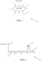
- FIG. 1 is a block diagram of an example system, indicated generally by the reference numeral 10.
- System 10 comprises a user device 1 that receives sensor data 2 from one or more sensors. At least one of the one or more sensors may be comprised within the user device 1.
- At least one of the one or more sensors may be external sensors, for example, comprised within one or more external devices.
- the sensor data 2 may comprise one or more of visual data, audible data, haptic data, motion data, radiofrequency data, environmental data (e.g. temperature, humidity, etc.) or the like.
- the user device 1 may analyse the sensor data 2 in order to predict an occurrence of an event. This is explained in further detail below.
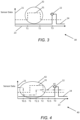
- FIG. 3 is a plot of sensor data, the plot indicated generally by the reference numeral 30, in accordance with an example embodiment.
- the plot 30 shows the sensor data axis 21, the time axis 23, and first sensor data plot 24, and the first event 22, as shown in FIG. 2 .
- the plot 30 further comprises a second sensor data plot 31.
- the second sensor data plot 31 may be based on second sensor data that may be received prior to the first event 22.
- the second sensor data may, for example, be received as a signal.
- the second sensor data received prior to the first event 22 may be analysed for recognizing or detecting one or more pre-event signatures 32 that are indicative of a prediction of the first event 22.
- a second sensor data signature may comprise the rise in the second sensor data at T1, and a fall in the second sensor data at T2.
- the second sensor data signature may be comprised within the pre-event signature 32 corresponding to the first event 22. Therefore, when the second sensor data signature is recognized or detected, it may be determined that the first event 22 is predicted to occur. For example, with reference to time T3 (the starting time of the first event 22), time T1 may be two minutes before time T3, and time T2 may be one minute before time T3.
- a pre-event signature 32 may therefore indicate that approximately two minutes after a start (rising edge) of the second sensor data, the first event 22 is predicted to occur.
- the first event 22 may be predicted to occur approximately one minute after an end (falling edge) of the second sensor data.
- the first event 22 may be predicted to occur when the second sensor data plot 31 shows that there is a rise in the second sensor data and a fall in the second sensor data in less than one minute after the rise in the second sensor data; and the first event 22 may be predicted to occur approximately one minute after the fall in the second sensor data.
- the first event 22 may be predicted to occur approximately one minute and thirty second after the second sensor data has been high for at least thirty seconds.
- start or finish of light being on or off rate of light flashing, number of light flashes, etc.
- frequency e.g. colour of the light
- wavelength e.g. position on the electromagnetic spectrum; visible or not visible to naked eye
- amplitude e.g. intensity or brightness of the light
- the first event 22 may be an audible event, such as a sound made by a heater, for example as the materials of the heater expand during heating.
- the sound from the heater may be a disruptive noise, and may cause disturbance to one or more users (for example, if someone is sleeping).
- a light of the heater may turn on a threshold time before the first event 22, that is, a threshold time before the heater makes a disruptive sound.
- the threshold time may be thirty seconds. Therefore, the second sensor data plot 31 may show visual sensor data captured from the light of the heater.
- a pre-event signature for the first event 22 (sound from the heater) may therefore comprise the second sensor data signature, which second sensor data signature is the turning on of the light thirty seconds before the first event 22.
- FIG. 4 is a plot of sensor data, the plot indicated generally by the reference numeral 40, in accordance with an example embodiment.
- the plot 40 shows the sensor data axis 21, the time axis 23, the first sensor data plot 24, the first event 22, and the second sensor data plot 31, as shown in FIG. 2 .
- the plot 40 further comprises a third sensor data plot 41.
- the second sensor data plot 31 and the third sensor data plot 41 may respectively be based on second sensor data and third sensor data that may be received prior to the first event 22.
- the second sensor data and the third signal data may, for example, be received as a second signal and a third signal respectively.
- the second sensor data and the third sensor data received prior to the first event 22 may be analysed for determining one or more pre-event signatures 42 that are indicative of a prediction of the first event 22.
- a third sensor data signature may comprise the fall in the third sensor data at T0.5, and a rise in the third sensor data at T1.5.
- the third sensor data signature may comprise one or more parameters.
- the second sensor data signature and the third sensor data signature may be comprised within the pre-event signature 42 corresponding to the first event 22. Therefore, when both the second sensor data signature and the third sensor data signature are detected, it may be determined that the first event 22 is predicted to occur.
- the first event 22 may be an audible event, such as a sound from a heater.
- a light of the heater may turn on when the heater is switched on.
- the heater may only start heating, and thus making the sound (the first event 22) a threshold time after the room temperature falls below a threshold temperature.
- the threshold time may be thirty seconds, and the threshold temperature may be 10 degree Celsius.
- the heater may make a sound (start heating) when the heater is on (light is on), and the temperature is below 10 degree Celsius. If the heater is on, but the temperature is not below 10 degree Celsius, the heater does not start heating, and therefore may not make a sound (first event 22 does not occur).
- the second sensor data plot 31 may show visual sensor data captured from the light of the heater
- the third sensor data plot 41 may show temperature sensor data captured with one or more temperature sensors (for example, comprised in a thermostat).
- the second signal data plot 31 shows an example timing of the light turning on, such that the first event 22 may be predicted to occur at any time after the light is turned on.
- the heater may be turned on any time before the first event 22, but the first event 22 will only occur thirty seconds after the temperature falls below 10 degree Celsius.
- a pre-event signature for the first event 22 (sound from the heater) may therefore comprise the second sensor data signature (light turned on) and the third sensor data signature (temperature falling below 10 degree Celsius).
- a pre-event signature is detected for a first event.
- the pre-event signature may be indicative of a prediction of a first event (e.g. including the nature and the timing of the first event).
- the pre-event signature may comprise one or more of: an audible signature, a visual signature, an environmental signature (such as temperature, humidity etc.), and a haptic signature.
- the first event may be one or more of: a visual event, an audible event, a haptic event and an environmental event.
- an event masking action is determined for the first event.
- the event masking action may be one or more of: a visual action, an audible action, a haptic action and an environmental action (such as turning on an air conditioning unit if the temperature is predicted to rise or turning on a humidifier if humidity is predicted to fall significantly).
- event masking may be implemented by the algorithm 50 based on predicted properties of an event (e.g. the time and/or nature of the event).
- the use of prediction may provide a predictive masking system that is not reliant of reactive masking of events.
- Reactive masking may comprise performing masking action(s) after the event has already started. This may cause at least the beginning of the event to not be masked. In some scenarios, the beginning or an initial part of an event may be disruptive enough for causing disturbance to one or more users.
- predictive masking allows performing masking action(s) before the event occurs, such that the beginning or initial part of the event is also masked from the one or more users. As such, the event may cause minimal disruption or disturbance to the one or more users, as the event is masked with the predictive masking action(s).
- the event masking action may be caused to be performed by the user device 1, such that the event masking action is performed at the user device 1.
- the user device 1 may cause the performance of the event masking action by causing another device to perform the event masking action.
- the user device 1 may send one or more instructions to one or more other devices for performing the event masking action.
- the event masking action comprises playing white noise in order to mask an audible event.
- the user device 1 may send an instruction to a speaker device, instructing the speaker device to play white noise.
- the speaker device may then perform the event masking action by playing the white noise.
- the pre-event signature may be determined using a signature matching algorithm (e.g.
- a similarity score may be determined, such that the similarity score is an indication of how similar a sensor data is to a pre-event signature. If a similarity score is within a threshold similarity score, the sensor data may be considered to match with the pre-event signature.
- the event-masking action may be determined for masking the first event.
- the pre-event signature database (described above) may further comprise one or more events corresponding to the pre-event signatures.
- the occurrence of a corresponding first event may be determined.
- An event masking action may be determined based on the first event, such that the event masking action may mitigate, cancel, or reduce some effects of the first event.
- an event masking action may be specified for one or more events, and a plurality of event masking actions may be defined for a plurality of events, and the plurality of event masking actions may be stored in a database.
- the masking operation determined in operation 52 may be of the same type as the event determined in operation 51 (e.g. a visual masking action may be used when the first event is a visual event, an audible masking action may be used when the first event is an audible event etc.). However, this is not essential to all example embodiments. For example, an environmental event (such as a change in light level) may be masked with an audible action or a visual action.
- the first event is an audible event
- an event masking action comprises an audio suppression action.
- an audio suppression action is determined by sending a query to a database comprising ideal audio suppression actions for audible events.
- An audio suppression action may comprise one or more of audio masking and audio cancellation.
- sound masking may be performed by generating a sound that may have a masking effect on the audible event.
- the sound may be generated using, for example, an artificial intelligence music generator, a white noise generator, a speech generator, or the like.
- one or more properties of the generated sound may be configured based on one or more properties of the audible event, such that the audible event may be masked.
- audio cancellation may be performed by generating an audio output to cancel one or more disruptive sounds of the audible event.
- the audio for audio cancellation may be generated using directed audio systems, broadcast audio systems, headphones, or any other device that may be used for cancelling the sound of the audible event.
- the audio for audio cancellation is generated at a location of a user.
- the audible event may occur in a first room, and a user may be located in a second room. The user may be able to hear one or more sounds of the audible event.
- the audio cancellation may be performed by generating the audio at the second room.
- the audio for audio cancellation is generated at a location of the audible event.
- the audio cancellation may be performed by generating the audio at the first room.
- Performing audio cancellation at the location of the audible event may allow the audio of the audible event to be suppressed for one or more nearby users in locations other than the second room.
- FIG. 6 is a plot of signal data, the plot indicated generally by the reference numeral 60, in accordance with an example embodiment.
- the plot 60 shows the signal data axis 21, the time axis 23, first sensor data plot 24, and the first event 22, as shown in FIG. 2 .
- the plot 60 further comprises a fourth signal data plot 61.
- the fourth signal data plot 61 may represent signals corresponding to an event masking action, as performed at operation 53 of FIG. 5 .
- the event masking action may start before the first event 22 is predicted to occur, and may end after the first event 22 is predicted to end. The event masking action is discussed in further detail in FIG. 9 .
- FIG. 7 is a block diagram of a system, indicated generally by the reference numeral 70, in accordance with an example embodiment.
- System 70 illustrates that a pre-event signature 71 may comprise one or more of an audible signature 72, a visual signature 73, an environmental signature 74, and a haptic signature 75.
- the audible signature 72 may comprise a specific frequency composition, amplitude, time of the sound, direction at which a sound originates, pattern of a sound wave, or any other detail that may define one or more sounds for the audible signature.
- the visual signature 73 may comprise information regarding any visual changes, such as a light turning on, a colour of the light, brightness of the light, a light turning off, a light flashing or blinking, any physical movement of any object, or the like.
- the environmental signature 74 may comprise information regarding any environmental changes, such as changes in temperature, changes in humidity, changes in air composition (for example, presence of smoke), changes in odour, or the like.
- the haptic signature 74 may comprise information regarding any haptic changes, such as vibrations, frequency of the vibrations, amplitude of the vibrations, time of the vibration, device at which vibration originates, or the like.
- environmental changes may include any changes in the relevant environment that may or may not include a visual, audible or haptic change.
- a pre-event signature may comprise a combination of one or more of an audible signature 72, a visual signature 73, an environmental signature 74, and a haptic signature 75.
- a thunderstorm may cause an audible change (sound of the thunder), a visual change (light from the lightning), environmental change (electrical discharge), and haptic change (vibrations).
- an environmental signature comprising information regarding any environmental changes may also fall within a scope of a visual, audible, and/or haptic signature.
- a rise in humidity may be accompanied by fog (visual signature).
- any changes may correspond to one or more of a visual, audible, haptic, and/or environmental signature.
- pre-event signatures are not limited to signatures which occur before the occurrence of the first event 22, such that the pre-event signature may correspond to sensor data received during or after the first event 22.
- a pre-event signature associated with an audible event may not necessarily be an audible signature and may be a side channel signature, for example, a radio-frequency signature, or may comprise sensor data from a visual microphone.
- the side channel signature may have a speed faster than the speed of the audible event.
- the pre-event signature may therefore occur during or after the sound of the audible event is generated, but the sensor data related to the pre-event signature may be received before the audio signals of the audible event are received.
- an event masking action may be performed for masking, cancelling, or reducing effects of the audible event.
- the pre-event signature 71 for a specific event may comprise a pattern or combination of the one or more of the audible signature 72, visual signature 73, environmental signature 74, and haptic signature 75.
- FIG. 8 is a block diagram of a system, indicated generally by the reference numeral 80, in accordance with an example embodiment.
- System 80 illustrates that the first event 81 (similar to the first event 22) may comprise one or more of an audible event 82, visual event 83, environmental event 84, and a haptic event 85.
- an audible event 82 may be a noise event, such as a disruptive noise that may cause disturbance to a user of the user device 1 and/or one or more other users hearing the disruptive noise.
- the visual event 83 may be an event that causes disturbance to the user or one or more users seeing the event.
- the visual event 83 may be, for example, a light turning on, a light turning off, a distracting movement of an object, or any other event that may be disruptive.
- the environmental event 84 may be, for example, changes in temperature, changes in humidity, changes in smell, or any other events that may be disruptive to the user and/or one or more other users.
- the haptic event 85 may be, for example, a vibration, a movement of an object, or any other disruptive event that the user or one or more other users may feel.
- the first event 22 may be a combination of one or more of the audible event 82, visual event 83, environmental event 84, and a haptic event 85.
- a lightning event (first event 22) may be a combination of a thunder (audible event 82), a flash of light (visual event 83), electrical discharge (environmental event 84), and vibrations (haptic event 85).
- an environmental event comprising any environmental changes may also fall within a scope of a visual, audible, and/or haptic event.
- Environmental changes may include changes in the environment that may or may not include an audible, visual, or haptic change.
- a rise in humidity may be accompanied by fog (visual event).
- any changes may correspond to one or more of a visual, audible, haptic, and/or environmental event.
- FIG. 9 is a block diagram of a system, indicated generally by the reference numeral 90, in accordance with an example embodiment.
- System 90 illustrates that the event masking action 91 may comprise one or more of an audible action 92, visual action 93, environmental action 94, and a haptic action 95.
- the event masking action may correspond to the type of event, i.e. an audible action 92 may be performed before an audible event 82; a visual action 93 may be performed before a visual event 83; an environmental action 94 may be performed before an environmental event 84; and a haptic action 95 may be performed before a haptic event 85.
- an audible action 92 may comprise generating an audio signal (such as white noise, or noise cancelling audio) for masking an audible event (first event 22).
- an audio signal such as white noise, or noise cancelling audio
- a visual action 93 may comprise generating a light for reducing effects of a visual event or creating a visual barrier between the user and the visual event.
- the first event 22 may be a flashing light in a room
- the event masking action may be to adjust lighting of the room in order to make the user or one or more other users in the room less distracted or disturbed by the flashing light.
- An environmental action 94 may comprise, for example, adjusting temperature, adjusting humidity, generating a smell, or the like.
- the first event 22 may be an outside temperature rising above a desired level. If the first event 22 is predicted to occur (e.g. the outside temperature is predicted to rise), an event masking action (such as the environmental action 94) may be performed by turning on an air conditioning system (before the outside temperature rises) for lowering the temperature, such that the user or one or more other users in the room are not disturbed by the rise in the outside temperature. Similarly, the first event 22 may be a fall in humidity. If the first event 22 is predicted to occur (e.g. the humidity is predicted to fall, perhaps below desired level), an event masking action (such as the environmental action 94) may be performed by turning on a humidifier.
- a haptic action 95 may comprise, for example, a vibration, a movement, applying heating to a body, applying cooling to a body or the like.
- the first event 22 may be a jolt from removing a car seat from a car seat holder in a car, which may cause a baby (user) sitting in the car seat to be disturbed or woken up from sleep.
- the first event 22 may be predicted to occur when a door of the car is opened (pre-event signature).
- An event masking action may comprise a haptic action 95.
- the haptic action 95 may be performed by gradually increasing a vibration of the car seat, such that the movement of the car seat gradually increases from a low level to a high level.
- the first event 22 may be a fall in room temperature which may cause a user to feel cold.
- the first event 22 may be predicted to occur when a window of the room is open and an outside temperature is below a threshold (pre-event signature).
- An event masking action may comprise a haptic action 95, which haptic action 95 may be performed by applying heating to body of the user (for example, via an electric heating blanket).
- the event masking action may be different than the type of the event, e.g. any of an audible action 92, visual action 93, environmental action 94, and haptic action 95 may be performed before any of the audible event 82, visual event 83, environmental event 84, and haptic event 85.
- a first event 22 is an audible event 82, such as a disruptive noise.
- An event masking action, such as a visual action 93 may be performed for distracting the user or one or more other users from the first event 22 (i.e. the disruptive noise).
- the first event 22 is a visual event, such as a sudden bright light turning on, which may be disturbing to a user (for example, a user that feels discomfort due to light sensitivity).
- an event masking action may include a haptic action 95, which haptic action 95 may comprise application of pressure on one or more pressure points of the user's body.
- application of pressure to the temples of the head may assist in mitigating discomfort of the user due to light sensitivity prior to the user being exposed to the sudden bright light.
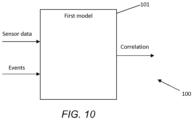
- FIG. 10 is a block diagram of a system, indicated generally by the reference numeral 100, in accordance with an example embodiment.
- the system 100 comprises a first model 101, which model may be used to determine a pre-event signature.
- the first model 101 receives as inputs a plurality of sensor data, and information of one or more events.
- the first model 101 may be used for determining a correlation between one or more sensor data features and one or more events.
- the one or more sensor data features may be determined from the sensor data inputs.
- the pre-event signature for one or more events may be stored in a database, such as the first model 101.
- the first model 101 may be trained over a large time period with a plurality of sensor data (for example, a large dataset for events and sensor data that may be comprised within a pre-event signature for one or more events).
- the first model 101 is trained by determining a correlation between one or more sensor data features and one or more events, such as the first event 22.
- One or more sensor data features may be associated with an event, such as the first event 22, if a uniqueness or repeatability of the one or more sensor data features in relation to the first event 22 is higher than a first threshold.
- the uniqueness of the one or more sensor data features in relation of the first event 22 may be higher than the first threshold if the occurrence of the sensor data features is generally followed by the first event 22.
- the repeatability of the one or more sensor data features in relation of the first event 22 may be higher than the first threshold if the occurrence of the first event 22 is generally preceded by the occurrence of the one or more sensor data features.
- the first model 101 may then be trained using the sensor data features associated with the first event.
- the first model 101 may, for example, be trained using machine-learning principles.
- the first model 101 may also be trained using unsupervised learning, for example, during the use of the first model.
- the first event 22 may be an audible event, such as a sound generated at a heater.
- a light of the heater may turn on a threshold time before the first event 22 occurs.
- the turning on of the light may be a sensor data feature.
- the first model 101 may be trained for the first event 22 (i.e. sound from the heater) over a training time period. During the training time period, the uniqueness of the sensor data feature of the light turning on may be determined based on whether, generally (for example the majority of the times when the light of the heater turns on), the light turning on is followed by the sound being generated at the heater.
- the uniqueness of the sensor data feature may be higher than the first threshold if it is determined that, generally (for example, the majority of the times when the light is turned on), the light turning on is followed by the sound being generated at the heater.
- the repeatability of the signal data feature of the light turning on may be determined based on whether, generally (for example the majority of the times when the sound is generated at the heater), the sound being generated at the heater is preceded by the light turning on.
- the repeatability of the signal data feature may be higher than the first threshold if it is determined that, generally (for example, the majority of the times that the sound is generated at the heater), the sound being generated at the heater is preceded by the light turning on.
- the training of the first model 101 may continue after the training time period, such that the first model 101 may be refined and/or updated during normal use of the first model 101.
- the first model may be trained using unsupervised learning, such that the first model 101 may not need to be pre-trained.
- a user may start using an apparatus of the above example embodiments, and the first model 101 may start learning correlations between sensor data features and events while the apparatus is in use.
- the first model 101 may comprise a neural network.
- One or more parameters of the first model 101 may be updated and/or refined based on machine learning principles in an unsupervised learning and/or by manual inputs from the user.
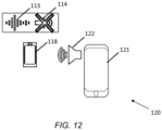
- FIG. 11 is a block diagram of a system, indicated generally by the reference numeral 110, in accordance with an example embodiment.
- System 110 comprises a user device 121, a first device 117, a second device 118, and a third device 119.
- the first device 117, the second device 118, and the third device 119 may generate one or more sounds or noises that may be disruptive or may cause disturbance to a user of the user device 121, or one or more other users.
- the first device 117 may generate a noise, which may be a first event 112.
- a pre-event signature 111 is determined to be indicative of a prediction of the first event 112.
- the second device 118 may generate a noise, which may be a second event 114.
- a pre-event signature 113 is determined to be indicative of a prediction of the first event 114.
- the third device 119 may generate a noise, which may be a third event 116.
- a pre-event signature 115 is determined to be indicative of a prediction of the third event 116.
- the user device 121 may receive sensor data for each of the pre-event signatures 111, 113, and 115, and may thus predict the occurrence of the first event 112, the second event 114, and the third event 116. As the user device 121 predicts the occurrence of the events, the user device 121 may perform one or more event masking actions to mask one or more of the first event 112, the second event 114, and the third event 116, as shown in FIG. 12 .
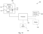
- FIG. 13 is a schematic diagram of components of one or more of the modules for implementing the algorithms described above, which hereafter are referred to generically as processing systems 300.
- a processing system 300 may have a processor 302, a memory 304 coupled to the processor and comprised of a RAM 314 and ROM 312, and, optionally, viewer inputs 310 and a display 318.
- the processing system 300 may comprise one or more network interfaces 308 for connection to a network, e.g. a modem which may be wired or wireless.
- the processor 302 is connected to each of the other components in order to control operation thereof.
- the memory 304 may comprise a non-volatile memory, a hard disk drive (HDD) or a solid state drive (SSD).
- the ROM 312 of the memory 304 stores, amongst other things, an operating system 315 and may store software applications 316.
- the RAM 314 of the memory 304 is used by the processor 302 for the temporary storage of data.
- the operating system 315 may contain code which, when executed by the processor, implements aspects of the algorithm 50.
- the processor 302 may take any suitable form. For instance, it may be a microcontroller, plural microcontrollers, a processor, or plural processors. Processor 302 may comprise processor circuitry.
- the processing system 300 may be a standalone computer, a server, a console, or a network thereof.
- the processing system 300 may also be associated with external software applications. These may be applications stored on a remote server device and may run partly or exclusively on the remote server device. These applications may be termed cloud-hosted applications.
- the processing system 300 may be in communication with the remote server device in order to utilize the software application stored there.
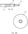
- FIG. 14A and FIG. 14B show tangible media, respectively a removable memory unit 365 and a compact disc (CD) 368, storing computer-readable code which when run by a computer may perform methods according to embodiments described above.
- the removable memory unit 365 may be a memory stick, e.g. a USB memory stick, having internal memory 366 storing the computer-readable code.
- the memory 366 may be accessed by a computer system via a connector 367.
- the CD 368 may be a CD-ROM or a DVD or similar. Other forms of tangible storage media may be used.
- references to, where relevant, "computer-readable storage medium”, “computer program product”, “tangibly embodied computer program” etc., or a “processor” or “processing circuitry” etc. should be understood to encompass not only computers having differing architectures such as single/multi-processor architectures and sequencers/parallel architectures, but also specialised circuits such as field programmable gate arrays FPGA, application specify circuits ASIC, signal processing devices and other devices.
- References to computer program, instructions, code etc. should be understood to express software for a programmable processor firmware such as the programmable content of a hardware device as instructions for a processor or configured or configuration settings for a fixed function device, gate array, programmable logic device, etc.
- circuitry refers to all of the following: (a) hardware-only circuit implementations (such as implementations in only analogue and/or digital circuitry) and (b) to combinations of circuits and software (and/or firmware), such as (as applicable): (i) to a combination of processor(s) or (ii) to portions of processor(s)/software (including digital signal processor(s)), software, and memory(ies) that work together to cause an apparatus, such as a server, to perform various functions) and (c) to circuits, such as a microprocessor(s) or a portion of a microprocessor(s), that require software or firmware for operation, even if the software or firmware is not physically present.
- the different functions discussed herein may be performed in a different order and/or concurrently with each other. Furthermore, if desired, one or more of the above-described functions may be optional or may be combined. Similarly, it will also be appreciated that the flow diagram of FIG. 5 is an example only and that various operations depicted therein may be omitted, reordered and/or combined.
Landscapes
- Engineering & Computer Science (AREA)
- Business, Economics & Management (AREA)
- Human Resources & Organizations (AREA)
- Physics & Mathematics (AREA)
- Theoretical Computer Science (AREA)
- Strategic Management (AREA)
- Economics (AREA)
- Tourism & Hospitality (AREA)
- Entrepreneurship & Innovation (AREA)
- General Physics & Mathematics (AREA)
- General Business, Economics & Management (AREA)
- Marketing (AREA)
- Multimedia (AREA)
- Quality & Reliability (AREA)
- General Health & Medical Sciences (AREA)
- Game Theory and Decision Science (AREA)
- Educational Administration (AREA)
- Development Economics (AREA)
- Health & Medical Sciences (AREA)
- Operations Research (AREA)
- Acoustics & Sound (AREA)
- Audiology, Speech & Language Pathology (AREA)
- Human Computer Interaction (AREA)
- General Engineering & Computer Science (AREA)
- Technology Law (AREA)
- Primary Health Care (AREA)
- User Interface Of Digital Computer (AREA)
- Soundproofing, Sound Blocking, And Sound Damping (AREA)
Claims (15)
- Vorrichtung (1), die Folgendes umfasst:Mittel zum Detektieren (51) einer Vorereignissignatur (71) auf Basis von Sensordaten (2), wobei die Vorereignissignatur (71) eine Vorhersage eines ersten Ereignisses (81) anzeigt, wobei das erste Ereignis (81) eine Art aufweist, die mindestens eines von visuell, akustisch oder haptisch umfasst;Mittel zum Bestimmen (52) einer Ereignismaskierungsaktion (91), die dem ersten Ereignis (81) entspricht, wobei die bestimmte Ereignismaskierungsaktion (91) dieselbe Art aufweist wie das erste Ereignis (81); undMittel zum Veranlassen einer Durchführung (53) der Ereignismaskierungsaktion (91) zum Maskieren des ersten Ereignisses (81) gegenüber einem Benutzer, wenn das erste Ereignis (81) eintritt, in Reaktion auf die Detektion (51) der Vorereignissignatur (71).
- Vorrichtung (1) nach Anspruch 1, wobei die Vorereignissignatur (71) eines oder mehreres von Folgendem umfasst: einer akustischen Signatur (72), einer visuellen Signatur (73), einer Umgebungssignatur (74) oder einer haptischen Signatur (75).
- Vorrichtung (1) nach Anspruch 1 oder Anspruch 2, wobei das erste Ereignis (81) eines oder mehreres von Folgendem ist: einem visuellen Ereignis (83), einem akustischen Ereignis (82), einem haptischen Ereignis (85) oder einem Umweltereignis (84).
- Vorrichtung nach einem der Ansprüche 1 bis 3, wobei die Ereignismaskierungsaktion (91) eines oder mehreres von Folgendem ist: einer visuellen Aktion (93), einer akustischen Aktion (92), einer haptischen Aktion (95) oder einer Umweltaktion (94).
- Vorrichtung nach einem der vorhergehenden Ansprüche, wobei das erste Ereignis (81) mindestens ein akustisches Ereignis (82) umfasst und die Ereignismaskierungsaktion (91) eine Audiounterdrückungsaktion (92) umfasst.
- Vorrichtung nach einem der vorhergehenden Ansprüche, wobei die Vorereignissignatur (71) unter Verwendung eines ersten Modells (101) bestimmt wird.
- Vorrichtung nach Anspruch 6, wobei das erste Modell (101) ein Maschinenlernmodell ist.
- Vorrichtung nach Anspruch 6 oder Anspruch 7, die ferner Mittel zum Trainieren des ersten Modells umfasst, wobei die Mittel zum Trainieren des ersten Modells Mittel zum Bestimmen einer Korrelation zwischen einem oder mehreren Sensordatenmerkmalen und dem ersten Ereignis (81) umfassen.
- Vorrichtung nach Anspruch 8, die ferner Mittel zum Verknüpfen von einem oder mehreren Sensordatenmerkmalen mit dem ersten Ereignis (81) umfasst, wenn von einem Eintreten der Sensordatenmerkmale bestimmt wird, dass demselben im Allgemeinen das erste Ereignis (81) folgt und/oder Eintreten dem ersten Ereignis (81) im Allgemeinen das Eintreten des einen oder der mehreren Sensordatenmerkmale vorausgeht, wobei das erste Modell (101) unter Verwendung von Sensordatenmerkmalen trainiert wird, die mit dem ersten Ereignis (81) verknüpft sind.
- Vorrichtung (1) nach einem der vorhergehenden Ansprüche, wobei die Mittel Folgendes umfassen:mindestens einen Prozessor (302); undmindestens einen Speicher (304), der einen Computerprogrammcode beinhaltet, wobei der mindestens eine Speicher (304) und der Computerprogrammcode dazu ausgelegt sind, mit dem mindestens einen Prozessor (302) die Durchführung des Verfahrens nach Anspruch 11 zu veranlassen.
- Verfahren (50), das Folgendes umfasst:Detektieren (51) einer Vorereignissignatur (71) auf Basis von Sensordaten (2), wobei die Vorereignissignatur (71) eine Vorhersage eines ersten Ereignisses (81) anzeigt, wobei das erste Ereignis (81) eine Art aufweist, die mindestens eines von visuell, akustisch oder haptisch umfasst;Bestimmen (52) einer Ereignismaskierungsaktion (91), die dem ersten Ereignis (81) entspricht, wobei die bestimmte Ereignismaskierungsaktion (91) dieselbe Art aufweist wie das erste Ereignis (81); undVeranlassen einer Durchführung (53) der Ereignismaskierungsaktion (91) zum Maskieren des ersten Ereignisses (81) gegenüber einem Benutzer, wenn das erste Ereignis (81) eintritt, in Reaktion auf die Detektion (51) der Vorereignissignatur (71).
- Verfahren (50) nach Anspruch 11, wobei:das erste Ereignis (81) eines oder mehreres von Folgendem ist: einem visuellen Ereignis (83), einem akustischen Ereignis (82), einem haptischen Ereignis (85) oder einem Umweltereignis (84); unddie Ereignismaskierungsaktion (91) eines oder mehreres von Folgendem ist: einer visuellen Aktion (93), einer akustischen Aktion (92), einer haptischen Aktion (95) oder einer Umweltaktion (94).
- Verfahren (50) nach einem der Ansprüche 11 und 12, wobei die Vorereignissignatur (71) unter Verwendung eines ersten Modells (101) bestimmt wird.
- Verfahren (50) nach einem der Ansprüche 11 bis 13, das das Trainieren des ersten Modells (101) mindestens auf Basis einer Korrelation zwischen einem oder mehreren Sensordatenmerkmalen und dem ersten Ereignis (81) umfasst.
- Computerprogramm, das Anweisungen zum Veranlassen einer Vorrichtung (1), mindestens Folgendes durchzuführen, umfasst:Detektieren (51) einer Vorereignissignatur (71) auf Basis von Sensordaten (2), wobei die Vorereignissignatur (71) eine Vorhersage eines ersten Ereignisses (81) anzeigt, wobei das erste Ereignis (81) eine Art aufweist, die mindestens eines von visuell, akustisch oder haptisch umfasst;Bestimmen (52) einer Ereignismaskierungsaktion (91), die dem ersten Ereignis (81) entspricht, wobei die bestimmte Ereignismaskierungsaktion (91) dieselbe Art aufweist wie das erste Ereignis (81); undVeranlassen einer Durchführung (53) der Ereignismaskierungsaktion (91) zum Maskieren des ersten Ereignisses (81) gegenüber einem Benutzer, wenn das erste Ereignis (81) eintritt, in Reaktion auf die Detektion (51) der Vorereignissignatur (71).
Priority Applications (4)
| Application Number | Priority Date | Filing Date | Title |
|---|---|---|---|
| EP19191702.0A EP3779810B1 (de) | 2019-08-14 | 2019-08-14 | Ereignismaskierung |
| US17/634,707 US12400628B2 (en) | 2019-08-14 | 2020-08-04 | Event masking |
| CN202080057355.8A CN114222969B (zh) | 2019-08-14 | 2020-08-04 | 事件掩蔽 |
| PCT/IB2020/057369 WO2021028780A1 (en) | 2019-08-14 | 2020-08-04 | Event masking |
Applications Claiming Priority (1)
| Application Number | Priority Date | Filing Date | Title |
|---|---|---|---|
| EP19191702.0A EP3779810B1 (de) | 2019-08-14 | 2019-08-14 | Ereignismaskierung |
Publications (2)
| Publication Number | Publication Date |
|---|---|
| EP3779810A1 EP3779810A1 (de) | 2021-02-17 |
| EP3779810B1 true EP3779810B1 (de) | 2025-06-25 |
Family
ID=67658799
Family Applications (1)
| Application Number | Title | Priority Date | Filing Date |
|---|---|---|---|
| EP19191702.0A Active EP3779810B1 (de) | 2019-08-14 | 2019-08-14 | Ereignismaskierung |
Country Status (4)
| Country | Link |
|---|---|
| US (1) | US12400628B2 (de) |
| EP (1) | EP3779810B1 (de) |
| CN (1) | CN114222969B (de) |
| WO (1) | WO2021028780A1 (de) |
Families Citing this family (1)
| Publication number | Priority date | Publication date | Assignee | Title |
|---|---|---|---|---|
| WO2022194381A1 (en) * | 2021-03-18 | 2022-09-22 | Telefonaktiebolaget Lm Ericsson (Publ) | Predict and trigger a future response to a predicted background noise based on a sequence of sounds |
Family Cites Families (15)
| Publication number | Priority date | Publication date | Assignee | Title |
|---|---|---|---|---|
| US7181027B1 (en) | 2000-05-17 | 2007-02-20 | Cisco Technology, Inc. | Noise suppression in communications systems |
| US20060116874A1 (en) * | 2003-10-24 | 2006-06-01 | Jonas Samuelsson | Noise-dependent postfiltering |
| TW200814708A (en) * | 2006-09-14 | 2008-03-16 | Benq Corp | Power save method and system for a mobile device |
| US20100172510A1 (en) | 2009-01-02 | 2010-07-08 | Nokia Corporation | Adaptive noise cancelling |
| US20130332156A1 (en) * | 2012-06-11 | 2013-12-12 | Apple Inc. | Sensor Fusion to Improve Speech/Audio Processing in a Mobile Device |
| CN105378826B (zh) | 2013-05-31 | 2019-06-11 | 诺基亚技术有限公司 | 音频场景装置 |
| US10169983B2 (en) | 2014-05-15 | 2019-01-01 | Honeywell International Inc. | Method of noise suppression for voice based interactive devices |
| WO2016033364A1 (en) | 2014-08-28 | 2016-03-03 | Audience, Inc. | Multi-sourced noise suppression |
| US9566980B2 (en) | 2015-03-05 | 2017-02-14 | Qualcomm Incorporated | Automobile driver improved response times using priming |
| US9754576B2 (en) | 2015-03-23 | 2017-09-05 | Ford Global Technologies, Llc | Control system for noise generated by functional hardware components |
| US9998804B2 (en) * | 2016-06-23 | 2018-06-12 | 3M Innovative Properties Company | Personal protective equipment (PPE) with analytical stream processing for safety event detection |
| US10169656B2 (en) * | 2016-08-29 | 2019-01-01 | Nec Corporation | Video system using dual stage attention based recurrent neural network for future event prediction |
| US10061312B1 (en) | 2017-03-30 | 2018-08-28 | Intel Corporation | Sensor management system for computer assisted vehicles |
| CN107609671A (zh) | 2017-08-10 | 2018-01-19 | 燕山大学 | 一种基于综合因素评价模型的短期电力负荷预测方法 |
| US10887351B2 (en) * | 2018-05-02 | 2021-01-05 | NortonLifeLock Inc. | Security for IoT home voice assistants |
-
2019
- 2019-08-14 EP EP19191702.0A patent/EP3779810B1/de active Active
-
2020
- 2020-08-04 US US17/634,707 patent/US12400628B2/en active Active
- 2020-08-04 CN CN202080057355.8A patent/CN114222969B/zh active Active
- 2020-08-04 WO PCT/IB2020/057369 patent/WO2021028780A1/en not_active Ceased
Also Published As
| Publication number | Publication date |
|---|---|
| CN114222969B (zh) | 2025-12-30 |
| WO2021028780A1 (en) | 2021-02-18 |
| US20220301535A1 (en) | 2022-09-22 |
| EP3779810A1 (de) | 2021-02-17 |
| US12400628B2 (en) | 2025-08-26 |
| CN114222969A (zh) | 2022-03-22 |
Similar Documents
| Publication | Publication Date | Title |
|---|---|---|
| CN110060685B (zh) | 语音唤醒方法和装置 | |
| US11862147B2 (en) | Method and system for enhancing the intelligibility of information for a user | |
| KR102915917B1 (ko) | 주변 소음 검출, 식별 및 관리를 위한 시스템 및 방법 | |
| US20170199934A1 (en) | Method and apparatus for audio summarization | |
| US9418665B2 (en) | Method for controlling device and device control system | |
| CN111868824A (zh) | 智能设备的情境感知控制 | |
| KR102288994B1 (ko) | 인공지능 기반의 이상음원 인식 장치, 그 방법 및 이를 이용한 관제시스템 | |
| CN109243442A (zh) | 声音监测方法、装置及头戴显示设备 | |
| US12495241B2 (en) | Apparatus and method for treating misophonia | |
| US12400628B2 (en) | Event masking | |
| US11030879B2 (en) | Environment-aware monitoring systems, methods, and computer program products for immersive environments | |
| CN111966321A (zh) | 音量调节方法、ar设备及存储介质 | |
| CN105852810B (zh) | 一种睡眠控制方法 | |
| EP4156134A1 (de) | Elektronisches überwachungssystem mit modifizierter audioausgabe | |
| EP3779967B1 (de) | Audioausgang mit eingebetteter authentifizierung | |
| KR101544671B1 (ko) | 소리 기반 저전력 전단 이벤트 감지 방법 및 장치 | |
| US20240155079A1 (en) | Configurable audio and video sectors | |
| US20210090573A1 (en) | Controlling a user interface | |
| CN112634883A (zh) | 控制用户界面 | |
| US20250310627A1 (en) | Systems, methods, and media for monitoring and engaging threats | |
| Maheshwari et al. | Context-Aware Adjustment of Noise Cancellation for Wearable Audio Devices | |
| CN115900008A (zh) | 助眠控制方法及装置、控制面板、存储介质 | |
| US20250124911A1 (en) | Audio cancellation | |
| CN114484814B (zh) | 用于控制空调语音的方法、装置、空调和存储介质 | |
| WO2026075675A1 (en) | Known-speaker-based and conditional selective pass-through for wearable audio components with active noise control |
Legal Events
| Date | Code | Title | Description |
|---|---|---|---|
| PUAI | Public reference made under article 153(3) epc to a published international application that has entered the european phase |
Free format text: ORIGINAL CODE: 0009012 |
|
| STAA | Information on the status of an ep patent application or granted ep patent |
Free format text: STATUS: THE APPLICATION HAS BEEN PUBLISHED |
|
| AK | Designated contracting states |
Kind code of ref document: A1 Designated state(s): AL AT BE BG CH CY CZ DE DK EE ES FI FR GB GR HR HU IE IS IT LI LT LU LV MC MK MT NL NO PL PT RO RS SE SI SK SM TR |
|
| AX | Request for extension of the european patent |
Extension state: BA ME |
|
| STAA | Information on the status of an ep patent application or granted ep patent |
Free format text: STATUS: REQUEST FOR EXAMINATION WAS MADE |
|
| 17P | Request for examination filed |
Effective date: 20210817 |
|
| RBV | Designated contracting states (corrected) |
Designated state(s): AL AT BE BG CH CY CZ DE DK EE ES FI FR GB GR HR HU IE IS IT LI LT LU LV MC MK MT NL NO PL PT RO RS SE SI SK SM TR |
|
| STAA | Information on the status of an ep patent application or granted ep patent |
Free format text: STATUS: EXAMINATION IS IN PROGRESS |
|
| 17Q | First examination report despatched |
Effective date: 20221018 |
|
| REG | Reference to a national code |
Ref country code: DE Ref legal event code: R079 Free format text: PREVIOUS MAIN CLASS: G06Q0010000000 Ipc: G06Q0010060000 Ref document number: 602019071469 Country of ref document: DE |
|
| GRAP | Despatch of communication of intention to grant a patent |
Free format text: ORIGINAL CODE: EPIDOSNIGR1 |
|
| STAA | Information on the status of an ep patent application or granted ep patent |
Free format text: STATUS: GRANT OF PATENT IS INTENDED |
|
| RIC1 | Information provided on ipc code assigned before grant |
Ipc: G06Q 50/18 20120101ALI20250205BHEP Ipc: G06Q 10/06 20120101AFI20250205BHEP |
|
| INTG | Intention to grant announced |
Effective date: 20250221 |
|
| GRAS | Grant fee paid |
Free format text: ORIGINAL CODE: EPIDOSNIGR3 |
|
| GRAA | (expected) grant |
Free format text: ORIGINAL CODE: 0009210 |
|
| STAA | Information on the status of an ep patent application or granted ep patent |
Free format text: STATUS: THE PATENT HAS BEEN GRANTED |
|
| AK | Designated contracting states |
Kind code of ref document: B1 Designated state(s): AL AT BE BG CH CY CZ DE DK EE ES FI FR GB GR HR HU IE IS IT LI LT LU LV MC MK MT NL NO PL PT RO RS SE SI SK SM TR |
|
| REG | Reference to a national code |
Ref country code: GB Ref legal event code: FG4D |
|
| REG | Reference to a national code |
Ref country code: CH Ref legal event code: EP |
|
| REG | Reference to a national code |
Ref country code: DE Ref legal event code: R096 Ref document number: 602019071469 Country of ref document: DE |
|
| REG | Reference to a national code |
Ref country code: CH Ref legal event code: EP |
|
| REG | Reference to a national code |
Ref country code: IE Ref legal event code: FG4D |
|
| PG25 | Lapsed in a contracting state [announced via postgrant information from national office to epo] |
Ref country code: FI Free format text: LAPSE BECAUSE OF FAILURE TO SUBMIT A TRANSLATION OF THE DESCRIPTION OR TO PAY THE FEE WITHIN THE PRESCRIBED TIME-LIMIT Effective date: 20250625 |
|
| PGFP | Annual fee paid to national office [announced via postgrant information from national office to epo] |
Ref country code: DE Payment date: 20250916 Year of fee payment: 7 |
|
| REG | Reference to a national code |
Ref country code: LT Ref legal event code: MG9D |
|
| PG25 | Lapsed in a contracting state [announced via postgrant information from national office to epo] |
Ref country code: GR Free format text: LAPSE BECAUSE OF FAILURE TO SUBMIT A TRANSLATION OF THE DESCRIPTION OR TO PAY THE FEE WITHIN THE PRESCRIBED TIME-LIMIT Effective date: 20250926 Ref country code: NO Free format text: LAPSE BECAUSE OF FAILURE TO SUBMIT A TRANSLATION OF THE DESCRIPTION OR TO PAY THE FEE WITHIN THE PRESCRIBED TIME-LIMIT Effective date: 20250925 |
|
| PG25 | Lapsed in a contracting state [announced via postgrant information from national office to epo] |
Ref country code: BG Free format text: LAPSE BECAUSE OF FAILURE TO SUBMIT A TRANSLATION OF THE DESCRIPTION OR TO PAY THE FEE WITHIN THE PRESCRIBED TIME-LIMIT Effective date: 20250625 |
|
| PGFP | Annual fee paid to national office [announced via postgrant information from national office to epo] |
Ref country code: GB Payment date: 20250911 Year of fee payment: 7 |
|
| PG25 | Lapsed in a contracting state [announced via postgrant information from national office to epo] |
Ref country code: HR Free format text: LAPSE BECAUSE OF FAILURE TO SUBMIT A TRANSLATION OF THE DESCRIPTION OR TO PAY THE FEE WITHIN THE PRESCRIBED TIME-LIMIT Effective date: 20250625 |
|
| PG25 | Lapsed in a contracting state [announced via postgrant information from national office to epo] |
Ref country code: RS Free format text: LAPSE BECAUSE OF FAILURE TO SUBMIT A TRANSLATION OF THE DESCRIPTION OR TO PAY THE FEE WITHIN THE PRESCRIBED TIME-LIMIT Effective date: 20250925 |
|
| PG25 | Lapsed in a contracting state [announced via postgrant information from national office to epo] |
Ref country code: LV Free format text: LAPSE BECAUSE OF FAILURE TO SUBMIT A TRANSLATION OF THE DESCRIPTION OR TO PAY THE FEE WITHIN THE PRESCRIBED TIME-LIMIT Effective date: 20250625 |
|
| REG | Reference to a national code |
Ref country code: NL Ref legal event code: MP Effective date: 20250625 |
|
| PG25 | Lapsed in a contracting state [announced via postgrant information from national office to epo] |
Ref country code: NL Free format text: LAPSE BECAUSE OF FAILURE TO SUBMIT A TRANSLATION OF THE DESCRIPTION OR TO PAY THE FEE WITHIN THE PRESCRIBED TIME-LIMIT Effective date: 20250625 |
|
| PG25 | Lapsed in a contracting state [announced via postgrant information from national office to epo] |
Ref country code: PT Free format text: LAPSE BECAUSE OF FAILURE TO SUBMIT A TRANSLATION OF THE DESCRIPTION OR TO PAY THE FEE WITHIN THE PRESCRIBED TIME-LIMIT Effective date: 20251027 |
|
| REG | Reference to a national code |
Ref country code: AT Ref legal event code: MK05 Ref document number: 1807283 Country of ref document: AT Kind code of ref document: T Effective date: 20250625 |
|
| PG25 | Lapsed in a contracting state [announced via postgrant information from national office to epo] |
Ref country code: IS Free format text: LAPSE BECAUSE OF FAILURE TO SUBMIT A TRANSLATION OF THE DESCRIPTION OR TO PAY THE FEE WITHIN THE PRESCRIBED TIME-LIMIT Effective date: 20251025 |
|
| PG25 | Lapsed in a contracting state [announced via postgrant information from national office to epo] |
Ref country code: AT Free format text: LAPSE BECAUSE OF FAILURE TO SUBMIT A TRANSLATION OF THE DESCRIPTION OR TO PAY THE FEE WITHIN THE PRESCRIBED TIME-LIMIT Effective date: 20250625 Ref country code: SM Free format text: LAPSE BECAUSE OF FAILURE TO SUBMIT A TRANSLATION OF THE DESCRIPTION OR TO PAY THE FEE WITHIN THE PRESCRIBED TIME-LIMIT Effective date: 20250625 |
|
| PG25 | Lapsed in a contracting state [announced via postgrant information from national office to epo] |
Ref country code: CZ Free format text: LAPSE BECAUSE OF FAILURE TO SUBMIT A TRANSLATION OF THE DESCRIPTION OR TO PAY THE FEE WITHIN THE PRESCRIBED TIME-LIMIT Effective date: 20250625 |
|
| PG25 | Lapsed in a contracting state [announced via postgrant information from national office to epo] |
Ref country code: PL Free format text: LAPSE BECAUSE OF FAILURE TO SUBMIT A TRANSLATION OF THE DESCRIPTION OR TO PAY THE FEE WITHIN THE PRESCRIBED TIME-LIMIT Effective date: 20250625 |
|
| PG25 | Lapsed in a contracting state [announced via postgrant information from national office to epo] |
Ref country code: EE Free format text: LAPSE BECAUSE OF FAILURE TO SUBMIT A TRANSLATION OF THE DESCRIPTION OR TO PAY THE FEE WITHIN THE PRESCRIBED TIME-LIMIT Effective date: 20250625 |
|
| PG25 | Lapsed in a contracting state [announced via postgrant information from national office to epo] |
Ref country code: SK Free format text: LAPSE BECAUSE OF FAILURE TO SUBMIT A TRANSLATION OF THE DESCRIPTION OR TO PAY THE FEE WITHIN THE PRESCRIBED TIME-LIMIT Effective date: 20250625 |
|
| PG25 | Lapsed in a contracting state [announced via postgrant information from national office to epo] |
Ref country code: ES Free format text: LAPSE BECAUSE OF FAILURE TO SUBMIT A TRANSLATION OF THE DESCRIPTION OR TO PAY THE FEE WITHIN THE PRESCRIBED TIME-LIMIT Effective date: 20250625 |
|
| PG25 | Lapsed in a contracting state [announced via postgrant information from national office to epo] |
Ref country code: RO Free format text: LAPSE BECAUSE OF FAILURE TO SUBMIT A TRANSLATION OF THE DESCRIPTION OR TO PAY THE FEE WITHIN THE PRESCRIBED TIME-LIMIT Effective date: 20250625 |
|
| REG | Reference to a national code |
Ref country code: CH Ref legal event code: H13 Free format text: ST27 STATUS EVENT CODE: U-0-0-H10-H13 (AS PROVIDED BY THE NATIONAL OFFICE) Effective date: 20260324 |
|
| PG25 | Lapsed in a contracting state [announced via postgrant information from national office to epo] |
Ref country code: MC Free format text: LAPSE BECAUSE OF FAILURE TO SUBMIT A TRANSLATION OF THE DESCRIPTION OR TO PAY THE FEE WITHIN THE PRESCRIBED TIME-LIMIT Effective date: 20250625 |
|
| PG25 | Lapsed in a contracting state [announced via postgrant information from national office to epo] |
Ref country code: DK Free format text: LAPSE BECAUSE OF FAILURE TO SUBMIT A TRANSLATION OF THE DESCRIPTION OR TO PAY THE FEE WITHIN THE PRESCRIBED TIME-LIMIT Effective date: 20250625 |
|
| PG25 | Lapsed in a contracting state [announced via postgrant information from national office to epo] |
Ref country code: LU Free format text: LAPSE BECAUSE OF NON-PAYMENT OF DUE FEES Effective date: 20250814 Ref country code: IT Free format text: LAPSE BECAUSE OF FAILURE TO SUBMIT A TRANSLATION OF THE DESCRIPTION OR TO PAY THE FEE WITHIN THE PRESCRIBED TIME-LIMIT Effective date: 20250625 |
|
| PG25 | Lapsed in a contracting state [announced via postgrant information from national office to epo] |
Ref country code: CH Free format text: LAPSE BECAUSE OF NON-PAYMENT OF DUE FEES Effective date: 20250831 |
|
| PLBE | No opposition filed within time limit |
Free format text: ORIGINAL CODE: 0009261 |
|
| STAA | Information on the status of an ep patent application or granted ep patent |
Free format text: STATUS: NO OPPOSITION FILED WITHIN TIME LIMIT |
|
| REG | Reference to a national code |
Ref country code: CH Ref legal event code: L10 Free format text: ST27 STATUS EVENT CODE: U-0-0-L10-L00 (AS PROVIDED BY THE NATIONAL OFFICE) Effective date: 20260507 |