EP3779603A1 - Image forming device - Google Patents
Image forming device Download PDFInfo
- Publication number
- EP3779603A1 EP3779603A1 EP18912956.2A EP18912956A EP3779603A1 EP 3779603 A1 EP3779603 A1 EP 3779603A1 EP 18912956 A EP18912956 A EP 18912956A EP 3779603 A1 EP3779603 A1 EP 3779603A1
- Authority
- EP
- European Patent Office
- Prior art keywords
- section
- print medium
- conveying
- controller
- image forming
- Prior art date
- Legal status (The legal status is an assumption and is not a legal conclusion. Google has not performed a legal analysis and makes no representation as to the accuracy of the status listed.)
- Granted
Links
Images


Classifications
-
- G—PHYSICS
- G03—PHOTOGRAPHY; CINEMATOGRAPHY; ANALOGOUS TECHNIQUES USING WAVES OTHER THAN OPTICAL WAVES; ELECTROGRAPHY; HOLOGRAPHY
- G03G—ELECTROGRAPHY; ELECTROPHOTOGRAPHY; MAGNETOGRAPHY
- G03G15/00—Apparatus for electrographic processes using a charge pattern
- G03G15/01—Apparatus for electrographic processes using a charge pattern for producing multicoloured copies
- G03G15/0105—Details of unit
- G03G15/0131—Details of unit for transferring a pattern to a second base
-
- G—PHYSICS
- G03—PHOTOGRAPHY; CINEMATOGRAPHY; ANALOGOUS TECHNIQUES USING WAVES OTHER THAN OPTICAL WAVES; ELECTROGRAPHY; HOLOGRAPHY
- G03G—ELECTROGRAPHY; ELECTROPHOTOGRAPHY; MAGNETOGRAPHY
- G03G15/00—Apparatus for electrographic processes using a charge pattern
- G03G15/20—Apparatus for electrographic processes using a charge pattern for fixing, e.g. by using heat
-
- G—PHYSICS
- G03—PHOTOGRAPHY; CINEMATOGRAPHY; ANALOGOUS TECHNIQUES USING WAVES OTHER THAN OPTICAL WAVES; ELECTROGRAPHY; HOLOGRAPHY
- G03G—ELECTROGRAPHY; ELECTROPHOTOGRAPHY; MAGNETOGRAPHY
- G03G15/00—Apparatus for electrographic processes using a charge pattern
- G03G15/20—Apparatus for electrographic processes using a charge pattern for fixing, e.g. by using heat
- G03G15/2003—Apparatus for electrographic processes using a charge pattern for fixing, e.g. by using heat using heat
- G03G15/2014—Apparatus for electrographic processes using a charge pattern for fixing, e.g. by using heat using heat using contact heat
- G03G15/2039—Apparatus for electrographic processes using a charge pattern for fixing, e.g. by using heat using heat using contact heat with means for controlling the fixing temperature
-
- G—PHYSICS
- G03—PHOTOGRAPHY; CINEMATOGRAPHY; ANALOGOUS TECHNIQUES USING WAVES OTHER THAN OPTICAL WAVES; ELECTROGRAPHY; HOLOGRAPHY
- G03G—ELECTROGRAPHY; ELECTROPHOTOGRAPHY; MAGNETOGRAPHY
- G03G15/00—Apparatus for electrographic processes using a charge pattern
- G03G15/20—Apparatus for electrographic processes using a charge pattern for fixing, e.g. by using heat
- G03G15/2003—Apparatus for electrographic processes using a charge pattern for fixing, e.g. by using heat using heat
- G03G15/2014—Apparatus for electrographic processes using a charge pattern for fixing, e.g. by using heat using heat using contact heat
- G03G15/2053—Structural details of heat elements, e.g. structure of roller or belt, eddy current, induction heating
-
- G—PHYSICS
- G03—PHOTOGRAPHY; CINEMATOGRAPHY; ANALOGOUS TECHNIQUES USING WAVES OTHER THAN OPTICAL WAVES; ELECTROGRAPHY; HOLOGRAPHY
- G03G—ELECTROGRAPHY; ELECTROPHOTOGRAPHY; MAGNETOGRAPHY
- G03G15/00—Apparatus for electrographic processes using a charge pattern
- G03G15/20—Apparatus for electrographic processes using a charge pattern for fixing, e.g. by using heat
- G03G15/2003—Apparatus for electrographic processes using a charge pattern for fixing, e.g. by using heat using heat
- G03G15/2014—Apparatus for electrographic processes using a charge pattern for fixing, e.g. by using heat using heat using contact heat
- G03G15/2064—Apparatus for electrographic processes using a charge pattern for fixing, e.g. by using heat using heat using contact heat combined with pressure
-
- G—PHYSICS
- G03—PHOTOGRAPHY; CINEMATOGRAPHY; ANALOGOUS TECHNIQUES USING WAVES OTHER THAN OPTICAL WAVES; ELECTROGRAPHY; HOLOGRAPHY
- G03G—ELECTROGRAPHY; ELECTROPHOTOGRAPHY; MAGNETOGRAPHY
- G03G15/00—Apparatus for electrographic processes using a charge pattern
- G03G15/20—Apparatus for electrographic processes using a charge pattern for fixing, e.g. by using heat
- G03G15/2096—Apparatus for electrographic processes using a charge pattern for fixing, e.g. by using heat using a solvent
-
- G—PHYSICS
- G03—PHOTOGRAPHY; CINEMATOGRAPHY; ANALOGOUS TECHNIQUES USING WAVES OTHER THAN OPTICAL WAVES; ELECTROGRAPHY; HOLOGRAPHY
- G03G—ELECTROGRAPHY; ELECTROPHOTOGRAPHY; MAGNETOGRAPHY
- G03G15/00—Apparatus for electrographic processes using a charge pattern
- G03G15/65—Apparatus which relate to the handling of copy material
- G03G15/6555—Handling of sheet copy material taking place in a specific part of the copy material feeding path
- G03G15/657—Feeding path after the transfer point and up to the fixing point, e.g. guides and feeding means for handling copy material carrying an unfused toner image
Definitions
- the present disclosures relates to an image forming apparatus.
- an image forming apparatus is provided with a fixing section which is configured to fix a toner image to a print medium.
- the fixing section sprays a fixing solution onto the print medium in which the toner image is formed so as to fix the toner image to the print medium (see Patent Literature 1 below).
- Patent Literature 1 Japanese Patent Application Laid-Open No. JP2017-68098A
- the fixing property of the toner image with respect to the print medium is lowered, in some cases, by a temperature of the environment in which the image forming apparatus is installed.
- an object of the present disclosure is to provide an image forming apparatus capable of suppressing any lowering in the fixing property of the toner image with respect to the print medium due to the temperature of environments in which the image forming apparatus is installed.
- the image forming apparatus of the present disclosure it is possible to suppress the lowering in the fixing property of the toner image with respect to the print medium due to the temperature of the environment in which the image forming apparatus is installed.
- the image forming apparatus 1 includes a body casing (main body casing) 2, a sheet feeding section 3, a toner image forming section 4, and a fixing section 5.
- the body casing 2 constructs the exterior of the image forming apparatus 1.
- the body casing 2 accommodates the sheet feeding section 3, the toner image forming section 4, and the fixing section 5.
- the sheet feeding section 3 is configured to supply or feed a print medium S to the toner image forming section 4. Specifically, the sheet feeding section 3 is configured to convey the print medium S toward an image carrier 6 of the toner image forming section 4.
- the toner image forming section 4 will be explained later on.
- the sheet feeding section 3 includes a paper feed tray 13, a pick-up roller 14, and a paper feed roller 15.
- the paper feed tray 13 is configured to accommodate the print medium S.
- the print medium S is, for example, printing paper (printing paper sheet, printing sheet).
- the pick-up roller 14 is configured to convey the print medium S in the inside of the paper feed tray 13 toward the paper feed roller 15.
- the paper feed roller 15 is configured to convey the print medium S from the pick-up roller 14 toward the image carrier 6.
- the toner image forming section 4 is configured to use a toner to thereby form a toner image in the print medium S.
- the toner image forming section 4 includes an image carrier 6, a charger 7, an exposure device 8, a developing device 9, and a transferring section 10.
- the image carrier 6 is configured to carry the toner image.
- the image carrier 6 is a photosensitive drum.
- the charger 7 is configured to charge a surface of the image carrier 6.
- the charger 7 is specifically a charging roller.
- the charger 7 may be a scorotron type charging device.
- the charger 7 makes contact with the surface of the image carrier 6.
- the charger 7 is positioned to be separated away from the surface of the image carrier 6 at a spacing distance.
- the exposure device 8 is configured to expose the surface of the image carrier 6. More specifically, the exposure device 8 is configured to expose the surface of the image carrier 6 charged by the charger 7. As a result, an electrostatic latent image is formed on the surface of the image carrier 6.
- the exposure device 8 is specifically a laser scan unit. Note that the exposure device 8 may be an LED array.
- the developing device 9 is configured to supply or feed the toner onto the surface of the image carrier 6. As a result, the electrostatic latent image is developed, and a toner image is formed on the surface of the image carrier 6.
- the developing device 9 includes a toner accommodating section 11 and a developing roller 12.
- the toner accommodating section 11 accommodates the toner.
- the toner contains toner particles, and as necessary or optionally, an external additive.
- the toner particles contain: a binder resin, and as necessary, a colorant, a pigment dispersant, a mold releasing agent, a magnetic body, and an electrostatic charge controlling agent.
- the binder resin is the base of the toner particles.
- the binder resin binds components contained in the toner particles.
- the binder resin is softened by the application of the fixing solution thereto, and then is cured so that the binder is firmly fixed to the print medium S.
- the colorant imparts a desired color to the toner particles.
- the colorant is dispersed in the binder resin.
- the pigment dispersant improves the dispersibility of the colorant.
- the electrostatic charge controlling agent imparts the electrostatic property to the toner particles.
- the electrostatic property may be either of the positive electrostatic charge or of the negative electrostatic charge.
- the external additive adjusts
- the developing roller 12 is configured to supply the toner inside the toner accommodating section 11 to the surface of the image carrier 6.
- the developing roller 12 makes contact with the image carrier 6. Note that it is allowable that the developing roller 12 makes no contact with the image carrier 6.
- the developing device 9 may be configured as a single process unit, together with the image carrier 6 and the charger 7.
- the process unit may be installable with respect to the body casing 2.
- the developing device 9 may be a developing cartridge which is installable with respect to a drum unit having the image carrier 6 and the charger 7.
- the drum unit may be installable with respect to the body casing 2.
- the developing device 9 may include a developer which includes the developing roller 12, and a toner cartridge which is installable with respect to the developer.
- the toner cartridge is provided with the toner accommodating section 11.
- the developer may be provided on the drum unit. The developer may be installable with respect to the drum unit.
- the transferring section 10 is configured to transfer the toner image formed on the surface of the image carrier 6 to the print medium S. Further, the transferring section 10 is configured to convey, together with the image carrier 6, the print medium S. Specifically, the transferring section 10 is a transfer roller. The transferring section 10 makes contact with the image carrier 6. Note that it is allowable that the transferring section 10 makes no contact with image carrier 6. Further note that the transferring section 10 may be, for example, a transfer belt.
- the fixing section 5 applies the fixing solution to the print medium S, conveyed by the image carrier 6 and the transferring section 10, so as to fix the toner image to the print medium S.
- the fixing solution is applied to the print medium S, in which the toner image is formed by the toner image forming section 4, so as to fix the toner image to the print medium S.
- the fixing section 5 is a fixing device which sprays the fixing solution by electrostatic spraying.
- the fixing section 5 may be a fixing device having a fixing roller configured to apply the fixing solution, or a fixing device having a piezoelectric device configured to apply the fixing solution.
- the print medium S which has passed the fixing section 5 is discharged, by the conveying section 21, to the upper surface of the body casing 2.
- the conveying section 21 will be explained later.
- the image forming apparatus 1 further includes a conveying section 21, a temperature sensor 22, a heater 23, a driving source 24 (see Fig. 2 ), and a controller 25 (see Fig. 2 ).
- the conveying section 21 conveys the print medium S which has passed the fixing section 5.
- the conveying section 21 includes a plurality of conveying rollers 26A, 26B, and a plurality of discharge rollers 27A, 27B.
- the conveying roller 26A conveys, together with the conveying roller 26B, the print medium S which has passed the fixing section 5 toward the discharge roller 27A.
- the conveying roller 26A makes contact with the conveying roller 26B.
- the print medium S passes between the conveying roller 26A and the conveying roller 26B.
- the discharge roller 27A discharges, together with the discharge roller 27B, the print medium S that has passed between the conveying roller 26A and the conveying roller 26B to the outside of the body casing 2.
- the discharge roller 27A makes contact with the discharge roller 27B.
- the print medium S passes between the discharge roller 27A and the discharge roller 27B.
- the temperature sensor 22 measures a temperature in (inside, in the inside of) the body casing 2. Specifically, the temperature sensor 22 measures a temperature in the vicinity of the fixing section 5. More specifically, the temperature sensor 22 measures a temperature in a space between the transferring section 10 and the fixing section 5.
- the heater 23 heats the print medium S which has passed the fixing section 5.
- the heater 23 is positioned between the fixing section 5 and the conveying section 21.
- the heater 23 does not have any contact with the print medium S in a case that the heater heats the print medium S.
- the heater 23 is a halogen lamp.
- the heater 23 may be a roller which makes contact with the print medium S.
- the driving source 24 drives the conveying section 21, the image carrier 6 and the transferring section 10.
- the driving source 24 is a motor.
- the driving source 24 is connected to the plurality of conveying rollers 26A, 26B and the plurality of the discharge rollers 27A, 27B of the conveying section 21, the image carrier 6, and the transferring section 10 via a power transmission mechanism (not depicted in the drawings).
- the power transmission mechanism may include a gear train and/or a clutch.
- the motive power from the driving source 24 is transmitted to the plurality of the conveying roller 26A and 26B and the plurality of the discharge rollers 27A and 27B of the conveying section 21, the image carrier 6, and the transferring section 10 via the gear train (not depicted in the drawings).
- the controller 25 controls the temperature sensor 22, the fixing section 5, the heater 23, the driving source 24, and the power transmitting mechanism (which is not depicted in the drawings). Further, the controller 25 controls the driving source 24 or the power transmitting mechanism (not depicted in the drawings) to thereby control the conveying section 21, the image carrier 6, and the transferring section 10.
- the controller 25 is electrically connected to the temperature sensor 22, the fixing section 5, the heater 23, the driving source 24, and the power transmitting mechanism (which is not depicted in the drawings), via a signal trace (which is not depicted in the drawings).
- the controller 25 may be, for example, a control circuit board provided with a memory and an ASIC. Alternatively, the controller 25 may be a control circuit board provided with a memory and a CPU.
- the controller 25 controls a conveying velocity (S4) of the print medium S by the conveying section 21, a conveying velocity (S5) of the print medium S by the image carrier 6 and the transferring section 10, and a heating temperature (S6) of the heater 23, based on a printing condition (S1) and a temperature (S2) in the body casing 2 so as to optimize a fixing condition.
- the controller 25 obtains a printing condition of the print job (step S1).
- the printing condition is exemplified, for example, by: the kind of the print medium S, the image quality of the toner image, the number of sheets (paper sheets) on which the printing is to be performed, etc.
- the controller 25 may control an application amount of the fixing solution to be applied by the fixing section 5 and a heating temperature of the heater 23, based on the printing condition.
- the controller 25 has data of coefficients corresponding to the respective kinds of the printing condition which are the kind of the print medium S, the image quality of the toner image, the number of sheets to which the printing is to be performed, etc.
- a memory of the controller 25 has the data of coefficients corresponding to the respective kinds of the printing condition which are the kind of the print medium S, the image quality of the toner image, the number of sheets to which the printing is to be performed, etc.
- the controller 25 controls the application amount of the fixing solution, in accordance with the printing condition, by multiplying a reference value of the application amount of the fixing solution by a coefficient based on the printing condition. Further, the controller 25 controls the heating temperature of the heater 23, in accordance with the printing condition, by multiplying a reference value of the heating temperature of the heater 23 by a coefficient based on the printing condition. Specifically, the ASIC or the CPU of the controller 25 controls the application amount of the fixing solution in accordance with the printing condition by multiplying the reference value of the application amount of the fixing solution stored in the memory of the controller 25 by the coefficient based on the printing condition stored in the memory of the controller 25.
- the ASIC or the CPU of the controller 25 controls the heating temperature of the heater 23 in accordance with the printing condition by multiplying the reference value of the heating temperature of the heater 23 stored in the memory of the controller 25 by the coefficient based on the printing condition stored in the memory of the controller 25.
- the controller 25 controls the application amount of the fixing solution to be applied by the fixing section 5 in accordance with the image quality of the toner image. Further, the controller 25 controls the heating temperature of the heater 23 in accordance with the application amount of the fixing solution to be applied by the fixing section 5. Specifically, in a case that the image quality of the toner image is a high image quality, the controller 25 controls the fixing section 5 so that the application amount of the fixing solution to be applied by the fixing section 5 is increased. Further, in a case that the controller 25 increases the application amount of the fixing solution to be applied by the fixing section 5, the controller 25 controls the heater 23 so that the heating temperature of the heater 23 is raised to be high.
- the controller 25 controls the fixing section 5 so that the application amount of the fixing solution to be applied by the fixing section 5 is reduced to be small. Moreover, in a case that the controller 25 reduces the application amount of the fixing solution to be applied by the fixing section 5, the controller 25 controls the heater 23 so that the heating temperature of the heater 23 is lowered.
- controller 25 obtains a temperature T measured by the temperature sensor 22 (step S2).
- the controller 25 determines whether or not the temperature T is higher than a threshold value T1 (step S3).
- the threshold value T 1 is, for example, in a range of not less than 0°C to not more than 10°C. Specifically, the threshold value T1 is 10°C.
- step S4 the controller 25 controls the image carrier 6 and the transferring section 10 so as to make the conveying velocity of the print medium S by the image carrier 6 and the transferring section 10 to be a first conveying velocity (step S4).
- step S5 the controller 25 controls the conveying section 21 so as to make the conveying velocity of the print medium S by the conveying section 21 to be a first velocity (step S5).
- the first velocity is a velocity same as the first conveying velocity.
- the controller 25 controls the rotation rate (number of rotations) of the driving source 24 to thereby make the conveying velocity of the print medium S by the image carrier 6 and the transferring section 10 to be the first conveying velocity and to thereby make the conveying velocity of the print medium S by the conveying section 21 to be the first velocity.
- the controller 25 controls the heating temperature of the heater 23, in accordance with the temperature T. Specifically, in the case that the temperature T is higher than the threshold value T1 (step S3 : YES), the controller 25 controls the heater 23 so as to make the heating temperature of the heater 23 to be a first heating temperature (step S6).
- the first heating temperature is, for example, in a range of not less than 40°C to not more than 90°C. It is preferred that the first heating temperature is in a range of not less than 50°C to not more than 70°C.
- the controller 25 executes the printing at the first conveying velocity, the first velocity, and the first heating temperature.
- step S7 the controller 25 controls the image carrier 6 and the transferring section 10 so as to make the conveying velocity of the print medium S by the image carrier 6 and the transferring section 10 to be a second conveying velocity which is slower than the first conveying velocity (step S7).
- the temperature T is lower than the threshold value T1
- the second conveying velocity is preferably in a range of not less than 1/4 times to not more than 1/2 times the first conveying velocity.
- the controller 25 controls the conveying section 21 so as to make the conveying velocity of the print medium S by the conveying section 21 to be a second velocity which is slower than the first velocity (step S8). It is preferred that the second velocity is a velocity which is same as the second conveying velocity.
- the controller 25 may control the heater 23 so as to make the heating temperature of the heater 23 to be a second heating temperature which is higher than the first heating temperature.
- the heating temperature of the heater 23 By making the heating temperature of the heater 23 to be high, it is possible to fix, in a more ensured manner, the toner image to the print medium S.
- the second heating temperature is, for example, in a range of not less than 50°C to not more than 150°C.
- the second heating temperature is preferably in a range of not less than 60°C to not more than 80°C.
- the controller 25 controls the image carrier 6 and the transferring section 10 so as to make the conveying velocity of the print medium S by the image carrier 6 and the transferring section 10 to be the second conveying velocity which is slower than the first conveying velocity (step S7).
- the temperature T is lower than the threshold value T1
- step S7 in the case that the temperature T is lower than the threshold value T1 (step S3: NO), the controller 25 controls the conveying section 21 so as to make the conveying velocity of the print medium S by the conveying section 21 to be the second velocity which is slower than the first velocity (step S7).
- the temperature T is lower than the threshold value T1
- the controller 25 controls the heating temperature of the heater 23 in accordance with the application amount of the fixing solution to be applied by the fixing section 5. Specifically, in a case that the image quality of the toner image is a high image quality, the controller 25 controls the fixing section 5 so as to increase the application amount of the fixing solution, and the controller 25 controls the heater 23 so as to make the heating temperature of the heater 23 to be high. On the other hand, in a case that the image quality of the toner image is a low image quality, the controller 25 controls the fixing section 5 so as to reduce the application amount of the fixing solution, and the controller 25 controls the heater 23 so as to make the heating temperature of the heater 23 to be low.
- the image quality of the toner image is the high image quality, it is possible to secure a long period of time for fixing the toner image to the print medium S.
- the image quality of the toner image is the low image quality, it is possible to suppress the consumption of the fixing solution, and to suppress the consumption of electric power for heating the heater 23.
- the temperature sensor 22 measures the temperature in the vicinity of the fixing section 5, more specifically, the temperature in the space between the transferring section 10 and the fixing section 5.
- the controller 25 may control at least the conveying velocity of the print medium S by the image carrier 6 and the transferring section 10. Namely, the conveying velocity of the print medium S by the conveying section 21, and the heating temperature of the heater 23 may be constant.
- controller 25 may control at least the conveying velocity of the print medium S by the conveying section 21.
- the conveying velocity of the print medium S by the image carrier 6 and the transferring section 10 and the heating temperature of the heaters 23 may be constant.
Landscapes
- Physics & Mathematics (AREA)
- General Physics & Mathematics (AREA)
- Fixing For Electrophotography (AREA)
- Control Or Security For Electrophotography (AREA)
- Electrostatic Charge, Transfer And Separation In Electrography (AREA)
Abstract
Description
- The present disclosures relates to an image forming apparatus.
- Conventionally, an image forming apparatus is provided with a fixing section which is configured to fix a toner image to a print medium. The fixing section sprays a fixing solution onto the print medium in which the toner image is formed so as to fix the toner image to the print medium (see
Patent Literature 1 below). - [Patent Literature] Patent Literature 1: Japanese Patent Application Laid-Open No.
JP2017-68098A - In the image forming apparatus as described in
Patent Literature 1, the fixing property of the toner image with respect to the print medium is lowered, in some cases, by a temperature of the environment in which the image forming apparatus is installed. - In view of this situation, an object of the present disclosure is to provide an image forming apparatus capable of suppressing any lowering in the fixing property of the toner image with respect to the print medium due to the temperature of environments in which the image forming apparatus is installed.
-
- (1) An image forming apparatus of the present disclosure includes: a body casing, a toner image forming section, a fixing section, a heater, a temperature sensor, and a controller. The toner image forming section is configured to form a toner image onto a print medium. The toner image forming section has an image carrier and a transferring section. The transferring section is configured to transfer the toner image formed on a surface of the image carrier to the print medium. The transferring section is configured to convey the print medium together with the image carrier. The fixing section is configured to apply a fixing solution to the print medium conveyed by the image carrier and the transferring section such that the toner image is fixed onto the print medium. The heater is configured to heat the print medium having passed the fixing section. The temperature sensor is configured to measure a temperature in the body casing. The controller is configured to control the image carrier and the transferring section. In a case that the temperature measured by the temperature sensor is higher than a predetermined threshold value, the controller is configured to control the image carrier and the transferring section such that a conveying velocity of the print medium by the image carrier and the transferring section becomes a first conveying velocity. Further, in a case that the temperature measured by the temperature sensor is lower than the predetermined threshold value, the controller is configured to control the image carrier and the transferring section such that the conveying velocity of the print medium by the image carrier and the transferring section becomes a second conveying velocity which is slower than the first conveying velocity.
According to such a configuration, by slowing down the conveying velocity of the print medium by the image carrier and the transferring section, it is possible to lengthen a period of time during which the print medium having the fixing solution applied thereto passes (passes through) the heater.
With this, it is possible to secure a long period of time for fixing the toner image to the print medium in a case that the temperature is lower than the threshold value.
As a result, it is possible to suppress any lowering in the fixing property of the toner image with respect to the print medium due to the temperature of the environment in which the image forming apparatus is installed. - (2) The temperature sensor may be configured to measure a temperature in the vicinity of the fixing section.
- (3) The temperature sensor may be configured to measure a temperature in a space between the transferring section and the fixing section.
- (4) The threshold value may be in a range of not less than 0°C to not more than 10°C.
- (5) The second conveying velocity may be in a range of not less than 1/4 times to not more than 1/2 times the first conveying velocity.
- (6) The image forming apparatus may further include a conveying section. The conveying section is configured to convey the print medium having passed the fixing section. In the case that the temperature measured by the temperature sensor is higher than the predetermined threshold value, the controller is configured to control the conveying section such that a conveying velocity of the print medium by the conveying section becomes a first velocity. Further, in the case that the temperature measured by the temperature sensor is lower than the predetermined threshold value, the controller is configured to control the conveying section such that the conveying velocity of the print medium by the conveying section becomes a second velocity slower than the first velocity.
- (7) The heater may be positioned between the fixing section and the conveying section.
- (8) The controller may be configured to control a heating temperature of the heater in accordance with the temperature measured by the temperature sensor.
- (9) In the case that the temperature measured by the temperature sensor is higher than the predetermined threshold value, the controller may be configured to control the heater such that the heating temperature of the heater becomes a first heating temperature. Further, in the case that the temperature measured by the temperature sensor is lower than the predetermined threshold value, the controller may be configured to control the heater such that the heating temperature of the heater becomes a second heating temperature higher than the first heating temperature.
- (10) The controller may be configured to control an application amount of the fixing solution to be applied by the fixing section, in accordance with an image quality of the toner image. Further, the controller may be configured to control the heating temperature of the heater in accordance with the application amount of the fixing solution to be applied by the fixing section.
- (11) The heater may make no contact with the print medium in a case that the heater heats the print medium.
- (12) The image forming apparatus may include a driving source configured to drive the conveying section. The driving source may be configured to drive the image carrier and the transferring section.
- (13) An image forming apparatus may include a body casing, a toner image forming section, a fixing section, a heater, and a controller. The toner image forming section is configured to form a toner image onto a print medium. The fixing section is configured to apply a fixing solution to the toner image such that the toner image is fixed onto the print medium. The heater is configured to heat the print medium having passed the fixing section. The controller is configured to control an application amount of the fixing solution to be applied by the fixing section, in accordance with an image quality of the toner image. Further, the controller is configured to control a heating temperature of the heater in accordance with the application amount of the fixing solution to be applied by the fixing section.
- (14) An image forming apparatus may include a body casing, a toner image forming section, a fixing section, a conveying section, a temperature sensor, and a controller. The toner image forming section is configured to form a toner image onto a print medium. The fixing section is configured to apply a fixing solution to the toner image such that the toner image is fixed onto the print medium. The conveying section is configured to convey the print medium having passed the fixing section. The temperature sensor is configured to measure a temperature in the body casing. The controller is configured to control the conveying section. In a case that the temperature measured by the temperature sensor is higher than a predetermined threshold value, the controller is configured to control the conveying section such that a conveying velocity of the print medium becomes a first velocity. Further, in a case that the temperature measured by the temperature sensor is lower than the predetermined threshold value, the controller is configured to control the conveying section such that the conveying velocity of the print medium becomes a second velocity slower than the first velocity.
- According to the image forming apparatus of the present disclosure, it is possible to suppress the lowering in the fixing property of the toner image with respect to the print medium due to the temperature of the environment in which the image forming apparatus is installed.
-
-
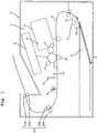
Fig. 1 is a view depicting the schematic configuration of an image forming apparatus. -
Fig. 2 is a block diagram for explaining the electrical connection among respective parts, sections and/or components of, and the transmission of the power (motive power) in the image forming apparatus depicted inFig. 1 . -
Fig. 3 is a flowchart for explaining the fixing control of the image forming apparatus depicted inFig. 1 . - The overall schematic of an
image forming apparatus 1 will be explained, with reference toFig. 1 . - The
image forming apparatus 1 includes a body casing (main body casing) 2, asheet feeding section 3, a tonerimage forming section 4, and afixing section 5. - The
body casing 2 constructs the exterior of theimage forming apparatus 1. Thebody casing 2 accommodates thesheet feeding section 3, the tonerimage forming section 4, and thefixing section 5. - The
sheet feeding section 3 is configured to supply or feed a print medium S to the tonerimage forming section 4. Specifically, thesheet feeding section 3 is configured to convey the print medium S toward animage carrier 6 of the tonerimage forming section 4. The tonerimage forming section 4 will be explained later on. Thesheet feeding section 3 includes apaper feed tray 13, a pick-uproller 14, and apaper feed roller 15. Thepaper feed tray 13 is configured to accommodate the print medium S. The print medium S is, for example, printing paper (printing paper sheet, printing sheet). The pick-uproller 14 is configured to convey the print medium S in the inside of thepaper feed tray 13 toward thepaper feed roller 15. Thepaper feed roller 15 is configured to convey the print medium S from the pick-uproller 14 toward theimage carrier 6. - The toner
image forming section 4 is configured to use a toner to thereby form a toner image in the print medium S. The tonerimage forming section 4 includes animage carrier 6, a charger 7, anexposure device 8, a developingdevice 9, and a transferringsection 10. - The
image carrier 6 is configured to carry the toner image. Specifically, theimage carrier 6 is a photosensitive drum. - The charger 7 is configured to charge a surface of the
image carrier 6. The charger 7 is specifically a charging roller. Note that the charger 7 may be a scorotron type charging device. In a case that the charger 7 is the charging roller, the charger 7 makes contact with the surface of theimage carrier 6. In a case that the charger 7 is the scorotron type charging device, the charger 7 is positioned to be separated away from the surface of theimage carrier 6 at a spacing distance. - The
exposure device 8 is configured to expose the surface of theimage carrier 6. More specifically, theexposure device 8 is configured to expose the surface of theimage carrier 6 charged by the charger 7. As a result, an electrostatic latent image is formed on the surface of theimage carrier 6. Theexposure device 8 is specifically a laser scan unit. Note that theexposure device 8 may be an LED array. - The developing
device 9 is configured to supply or feed the toner onto the surface of theimage carrier 6. As a result, the electrostatic latent image is developed, and a toner image is formed on the surface of theimage carrier 6. The developingdevice 9 includes atoner accommodating section 11 and a developingroller 12. - The
toner accommodating section 11 accommodates the toner. The toner contains toner particles, and as necessary or optionally, an external additive. The toner particles contain: a binder resin, and as necessary, a colorant, a pigment dispersant, a mold releasing agent, a magnetic body, and an electrostatic charge controlling agent. The binder resin is the base of the toner particles. The binder resin binds components contained in the toner particles. The binder resin is softened by the application of the fixing solution thereto, and then is cured so that the binder is firmly fixed to the print medium S. The colorant imparts a desired color to the toner particles. The colorant is dispersed in the binder resin. The pigment dispersant improves the dispersibility of the colorant. The electrostatic charge controlling agent imparts the electrostatic property to the toner particles. The electrostatic property may be either of the positive electrostatic charge or of the negative electrostatic charge. The external additive adjusts the electrostatic property, the fluidity, the storage stability of the toner particles. - The developing
roller 12 is configured to supply the toner inside thetoner accommodating section 11 to the surface of theimage carrier 6. The developingroller 12 makes contact with theimage carrier 6. Note that it is allowable that the developingroller 12 makes no contact with theimage carrier 6. - The developing
device 9 may be configured as a single process unit, together with theimage carrier 6 and the charger 7. The process unit may be installable with respect to thebody casing 2. - Further, the developing
device 9 may be a developing cartridge which is installable with respect to a drum unit having theimage carrier 6 and the charger 7. The drum unit may be installable with respect to thebody casing 2. - Further, the developing
device 9 may include a developer which includes the developingroller 12, and a toner cartridge which is installable with respect to the developer. In such a case, the toner cartridge is provided with thetoner accommodating section 11. Further, the developer may be provided on the drum unit. The developer may be installable with respect to the drum unit. - The transferring
section 10 is configured to transfer the toner image formed on the surface of theimage carrier 6 to the print medium S. Further, the transferringsection 10 is configured to convey, together with theimage carrier 6, the print medium S. Specifically, the transferringsection 10 is a transfer roller. The transferringsection 10 makes contact with theimage carrier 6. Note that it is allowable that the transferringsection 10 makes no contact withimage carrier 6. Further note that the transferringsection 10 may be, for example, a transfer belt. - The fixing
section 5 applies the fixing solution to the print medium S, conveyed by theimage carrier 6 and the transferringsection 10, so as to fix the toner image to the print medium S. In other words, the fixing solution is applied to the print medium S, in which the toner image is formed by the tonerimage forming section 4, so as to fix the toner image to the print medium S. Specifically, the fixingsection 5 is a fixing device which sprays the fixing solution by electrostatic spraying. Note that the fixingsection 5 may be a fixing device having a fixing roller configured to apply the fixing solution, or a fixing device having a piezoelectric device configured to apply the fixing solution. The print medium S which has passed thefixing section 5 is discharged, by the conveyingsection 21, to the upper surface of thebody casing 2. The conveyingsection 21 will be explained later. - As depicted in
Figs. 1 and2 , theimage forming apparatus 1 further includes a conveyingsection 21, atemperature sensor 22, aheater 23, a driving source 24 (seeFig. 2 ), and a controller 25 (seeFig. 2 ). - As depicted in
Fig. 1 , the conveyingsection 21 conveys the print medium S which has passed thefixing section 5. Specifically, the conveyingsection 21 includes a plurality of conveyingrollers discharge rollers - The conveying
roller 26A conveys, together with the conveyingroller 26B, the print medium S which has passed thefixing section 5 toward thedischarge roller 27A. The conveyingroller 26A makes contact with the conveyingroller 26B. The print medium S passes between the conveyingroller 26A and the conveyingroller 26B. - The
discharge roller 27A discharges, together with thedischarge roller 27B, the print medium S that has passed between the conveyingroller 26A and the conveyingroller 26B to the outside of thebody casing 2. Thedischarge roller 27A makes contact with thedischarge roller 27B. The print medium S passes between thedischarge roller 27A and thedischarge roller 27B. - The
temperature sensor 22 measures a temperature in (inside, in the inside of) thebody casing 2. Specifically, thetemperature sensor 22 measures a temperature in the vicinity of the fixingsection 5. More specifically, thetemperature sensor 22 measures a temperature in a space between the transferringsection 10 and thefixing section 5. - The
heater 23 heats the print medium S which has passed thefixing section 5. Theheater 23 is positioned between the fixingsection 5 and the conveyingsection 21. Theheater 23 does not have any contact with the print medium S in a case that the heater heats the print medium S. Specifically, theheater 23 is a halogen lamp. Note that theheater 23 may be a roller which makes contact with the print medium S. - As depicted in
Fig. 2 , the drivingsource 24 drives the conveyingsection 21, theimage carrier 6 and the transferringsection 10. Specifically, the drivingsource 24 is a motor. In a case that the drivingsource 24 is a motor, the drivingsource 24 is connected to the plurality of conveyingrollers discharge rollers section 21, theimage carrier 6, and the transferringsection 10 via a power transmission mechanism (not depicted in the drawings). The power transmission mechanism (not depicted in the drawings) may include a gear train and/or a clutch. Thus, the motive power from the drivingsource 24 is transmitted to the plurality of the conveyingroller discharge rollers section 21, theimage carrier 6, and the transferringsection 10 via the gear train (not depicted in the drawings). - As depicted in
Fig. 2 , thecontroller 25 controls thetemperature sensor 22, the fixingsection 5, theheater 23, the drivingsource 24, and the power transmitting mechanism (which is not depicted in the drawings). Further, thecontroller 25 controls the drivingsource 24 or the power transmitting mechanism (not depicted in the drawings) to thereby control the conveyingsection 21, theimage carrier 6, and the transferringsection 10. Thecontroller 25 is electrically connected to thetemperature sensor 22, the fixingsection 5, theheater 23, the drivingsource 24, and the power transmitting mechanism (which is not depicted in the drawings), via a signal trace (which is not depicted in the drawings). Thecontroller 25 may be, for example, a control circuit board provided with a memory and an ASIC. Alternatively, thecontroller 25 may be a control circuit board provided with a memory and a CPU. - Next, the fixing control of the
image forming apparatus 1 will be explained, with reference toFig. 3 . - As depicted in
Fig. 3 , thecontroller 25 controls a conveying velocity (S4) of the print medium S by the conveyingsection 21, a conveying velocity (S5) of the print medium S by theimage carrier 6 and the transferringsection 10, and a heating temperature (S6) of theheater 23, based on a printing condition (S1) and a temperature (S2) in thebody casing 2 so as to optimize a fixing condition. - The above-described control performed by the
controller 25 will be explained in detail as below. - In a case that a print job is inputted to the image forming apparatus, the
controller 25 obtains a printing condition of the print job (step S1). The printing condition is exemplified, for example, by: the kind of the print medium S, the image quality of the toner image, the number of sheets (paper sheets) on which the printing is to be performed, etc. - Note that the
controller 25 may control an application amount of the fixing solution to be applied by the fixingsection 5 and a heating temperature of theheater 23, based on the printing condition. Specifically, thecontroller 25 has data of coefficients corresponding to the respective kinds of the printing condition which are the kind of the print medium S, the image quality of the toner image, the number of sheets to which the printing is to be performed, etc. More specifically, a memory of thecontroller 25 has the data of coefficients corresponding to the respective kinds of the printing condition which are the kind of the print medium S, the image quality of the toner image, the number of sheets to which the printing is to be performed, etc. Thecontroller 25 controls the application amount of the fixing solution, in accordance with the printing condition, by multiplying a reference value of the application amount of the fixing solution by a coefficient based on the printing condition. Further, thecontroller 25 controls the heating temperature of theheater 23, in accordance with the printing condition, by multiplying a reference value of the heating temperature of theheater 23 by a coefficient based on the printing condition. Specifically, the ASIC or the CPU of thecontroller 25 controls the application amount of the fixing solution in accordance with the printing condition by multiplying the reference value of the application amount of the fixing solution stored in the memory of thecontroller 25 by the coefficient based on the printing condition stored in the memory of thecontroller 25. Furthermore, the ASIC or the CPU of thecontroller 25 controls the heating temperature of theheater 23 in accordance with the printing condition by multiplying the reference value of the heating temperature of theheater 23 stored in the memory of thecontroller 25 by the coefficient based on the printing condition stored in the memory of thecontroller 25. - More specifically, the
controller 25 controls the application amount of the fixing solution to be applied by the fixingsection 5 in accordance with the image quality of the toner image. Further, thecontroller 25 controls the heating temperature of theheater 23 in accordance with the application amount of the fixing solution to be applied by the fixingsection 5. Specifically, in a case that the image quality of the toner image is a high image quality, thecontroller 25 controls the fixingsection 5 so that the application amount of the fixing solution to be applied by the fixingsection 5 is increased. Further, in a case that thecontroller 25 increases the application amount of the fixing solution to be applied by the fixingsection 5, thecontroller 25 controls theheater 23 so that the heating temperature of theheater 23 is raised to be high. Furthermore, in a case that the image quality of the toner image is a low image quality, thecontroller 25 controls the fixingsection 5 so that the application amount of the fixing solution to be applied by the fixingsection 5 is reduced to be small. Moreover, in a case that thecontroller 25 reduces the application amount of the fixing solution to be applied by the fixingsection 5, thecontroller 25 controls theheater 23 so that the heating temperature of theheater 23 is lowered. - Further, the
controller 25 obtains a temperature T measured by the temperature sensor 22 (step S2). - Next, the
controller 25 determines whether or not the temperature T is higher than a threshold value T1 (step S3). - The
threshold value T 1 is, for example, in a range of not less than 0°C to not more than 10°C. Specifically, the threshold value T1 is 10°C. - In a case that the temperature T is higher than the threshold value T (step S3 : YES), the
controller 25 controls theimage carrier 6 and the transferringsection 10 so as to make the conveying velocity of the print medium S by theimage carrier 6 and the transferringsection 10 to be a first conveying velocity (step S4). - Further, in the case that the temperature T is higher than the threshold value T1 (step S3 : YES), the
controller 25 controls the conveyingsection 21 so as to make the conveying velocity of the print medium S by the conveyingsection 21 to be a first velocity (step S5). - It is preferred that the first velocity is a velocity same as the first conveying velocity. Specifically, the
controller 25 controls the rotation rate (number of rotations) of the drivingsource 24 to thereby make the conveying velocity of the print medium S by theimage carrier 6 and the transferringsection 10 to be the first conveying velocity and to thereby make the conveying velocity of the print medium S by the conveyingsection 21 to be the first velocity. - Further, the
controller 25 controls the heating temperature of theheater 23, in accordance with the temperature T. Specifically, in the case that the temperature T is higher than the threshold value T1 (step S3 : YES), thecontroller 25 controls theheater 23 so as to make the heating temperature of theheater 23 to be a first heating temperature (step S6). - The first heating temperature is, for example, in a range of not less than 40°C to not more than 90°C. It is preferred that the first heating temperature is in a range of not less than 50°C to not more than 70°C.
- Afterwards, the
controller 25 executes the printing at the first conveying velocity, the first velocity, and the first heating temperature. - On the other hand, in a case that the temperature T is lower than the threshold value T1 (step S3:NO), the
controller 25 controls theimage carrier 6 and the transferringsection 10 so as to make the conveying velocity of the print medium S by theimage carrier 6 and the transferringsection 10 to be a second conveying velocity which is slower than the first conveying velocity (step S7). - By slowing down the conveying velocity of the print medium S by the
image carrier 6 and the transferringsection 10, a period of time during which the print medium S, having the fixing solution applied thereto, passes theheater 23 can be made longer. - Therefore, in the case that the temperature T is lower than the threshold value T1, it is possible to secure a long period of time for fixing the toner image to the print medium S.
- As a result, it is possible to suppress the lowering in the fixing property of the toner image with respect to the print medium S due to the temperature of the environment in which the
image forming apparatus 1 is installed. - Note that the second conveying velocity is preferably in a range of not less than 1/4 times to not more than 1/2 times the first conveying velocity.
- Further, in the case that the temperature T is lower than the threshold value T1 (step S3: NO), the
controller 25 controls the conveyingsection 21 so as to make the conveying velocity of the print medium S by the conveyingsection 21 to be a second velocity which is slower than the first velocity (step S8). It is preferred that the second velocity is a velocity which is same as the second conveying velocity. - By slowing down the conveying velocity of the print medium S by the conveying
section 21, it is possible to make a period of time, since the fixing solution has been applied to the print medium and until the print medium S is discharged to the outside of thebody casing 2, to be long. - With this, in the case that the temperature T is lower than the threshold value T1, it is possible to secure a long period of time for fixing the toner image to the print medium S.
- Further, by slowing both the conveying velocity of the print medium S by the conveying
section 21 and the conveying velocity of the print medium S by theimage carrier 6 and the transferringsection 10, it is possible to increase the period of time during which the print medium S having the fixing solution applied thereto passes theheater 23, while conveying the print medium S at a stable conveying velocity; and it is possible to increase the period of time, since the fixing solution has been applied to the print medium S and until the print medium S is discharged to the outside thebody casing 2, to be long. - Further, in the case that the temperature T is lower than the threshold value T1 (step S3: NO), the
controller 25 may control theheater 23 so as to make the heating temperature of theheater 23 to be a second heating temperature which is higher than the first heating temperature. - By making the heating temperature of the
heater 23 to be high, it is possible to fix, in a more ensured manner, the toner image to the print medium S. - The second heating temperature is, for example, in a range of not less than 50°C to not more than 150°C. The second heating temperature is preferably in a range of not less than 60°C to not more than 80°C.
- According to the
image forming apparatus 1, in the case that the temperature T is lower than the threshold value T1 (step S3: NO) as depictedFig. 3 , thecontroller 25 controls theimage carrier 6 and the transferringsection 10 so as to make the conveying velocity of the print medium S by theimage carrier 6 and the transferringsection 10 to be the second conveying velocity which is slower than the first conveying velocity (step S7). - With this, it is possible to make the period of time during which the print medium S having the fixing solution applied thereto passes the
heater 23. - Therefore, in the case that the temperature T is lower than the threshold value T1, it is possible to secure a long period of time for fixing the toner image to the print medium S.
- As a result, it is possible to suppress the lowering in the fixing property of the toner image with respect to the print medium S due to the temperature of the environment in which the
image forming apparatus 1 is installed. - Further, according to the
image forming apparatus 1, as depicted inFig. 3 , in the case that the temperature T is lower than the threshold value T1 (step S3: NO), thecontroller 25 controls the conveyingsection 21 so as to make the conveying velocity of the print medium S by the conveyingsection 21 to be the second velocity which is slower than the first velocity (step S7). - With this, it is possible to make the period of time, since the fixing solution has been applied to the print medium S and until the print medium S is discharged to the outside of the
body casing 2, to be long. - Therefore, in the case that the temperature T is lower than the threshold value T1, it is possible to secure a long period of time for fixing the toner image to the print medium S.
- As a result, it is possible to suppress the lowering in the fixing property of the toner image with respect to the print medium S due to the temperature of the environment in which the
image forming apparatus 1 is installed. - Further, according to the
image forming apparatus 1, thecontroller 25 controls the heating temperature of theheater 23 in accordance with the application amount of the fixing solution to be applied by the fixingsection 5. Specifically, in a case that the image quality of the toner image is a high image quality, thecontroller 25 controls the fixingsection 5 so as to increase the application amount of the fixing solution, and thecontroller 25 controls theheater 23 so as to make the heating temperature of theheater 23 to be high. On the other hand, in a case that the image quality of the toner image is a low image quality, thecontroller 25 controls the fixingsection 5 so as to reduce the application amount of the fixing solution, and thecontroller 25 controls theheater 23 so as to make the heating temperature of theheater 23 to be low. - Therefore, in the case that the image quality of the toner image is the high image quality, it is possible to secure a long period of time for fixing the toner image to the print medium S. On the other hand, in the case that the image quality of the toner image is the low image quality, it is possible to suppress the consumption of the fixing solution, and to suppress the consumption of electric power for heating the
heater 23. - As a result, it is possible to suppress the lowering in the fixing property of the toner image with respect to the print medium S due to the temperature of the environment in which the
image forming apparatus 1 is installed, and it is also possible to suppress the consumption amount of the fixing solution and to suppress the consumption amount of the electric power for heating theheater 23. - Further, according to the
image forming apparatus 1, as depicted inFig. 1 , thetemperature sensor 22 measures the temperature in the vicinity of the fixingsection 5, more specifically, the temperature in the space between the transferringsection 10 and thefixing section 5. - Therefore, it is possible to control the conveying velocity of the print medium S and the heating temperature of the
heater 23, while monitoring the temperature in the vicinity of the fixingsection 5. - In the above-described embodiment, the
controller 25 may control at least the conveying velocity of the print medium S by theimage carrier 6 and the transferringsection 10. Namely, the conveying velocity of the print medium S by the conveyingsection 21, and the heating temperature of theheater 23 may be constant. - Further, the
controller 25 may control at least the conveying velocity of the print medium S by the conveyingsection 21. In such a case, the conveying velocity of the print medium S by theimage carrier 6 and the transferringsection 10 and the heating temperature of theheaters 23 may be constant. -
- 1:
- image forming apparatus
- 2:
- body casing
- 4:
- toner image forming section
- 5:
- fixing section
- 6:
- image carrier
- 10:
- transferring section
- 21:
- conveying section
- 22:
- temperature sensor
- 23:
- heater
- 24:
- driving source
- 25:
- controller
- S:
- print medium
Claims (14)
- An image forming apparatus comprising:a body casing;a toner image forming section configured to form a toner image onto a print medium, the toner image forming section including:an image carrier; anda transferring section configured to transfer the toner image formed on a surface of the image carrier to the print medium, and convey the print medium together with the image carrier;a fixing section configured to apply a fixing solution to the print medium conveyed by the image carrier and the transferring section such that the toner image is fixed onto the print medium;a heater configured to heat the print medium having passed the fixing section;a temperature sensor configured to measure a temperature in the body casing; anda controller configured to control the image carrier and the transferring section,wherein in a case that the temperature measured by the temperature sensor is higher than a predetermined threshold value, the controller is configured to control the image carrier and the transferring section such that a conveying velocity of the print medium by the image carrier and the transferring section becomes a first conveying velocity, andin a case that the temperature measured by the temperature sensor is lower than the predetermined threshold value, the controller is configured to control the image carrier and the transferring section such that the conveying velocity of the print medium by the image carrier and the transferring section becomes a second conveying velocity slower than the first conveying velocity.
- The image forming apparatus according to claim 1, characterized in that the temperature sensor is configured to measure a temperature in the vicinity of the fixing section.
- The image forming apparatus according to claim 2, characterized in that the temperature sensor is configured to measure a temperature in a space between the transferring section and the fixing section.
- The image forming apparatus according to any one of claims 1 to 3, characterized in that the threshold value is in a range of not less than 0°C to not more than 10°C.
- The image forming apparatus according to any one of claims 1 to 4, characterized in that the second conveying velocity is in a range of not less than 1/4 times to not more than 1/2 times the first conveying velocity.
- The image recording apparatus according to any one of claims 1 to 5, characterized by further comprising a conveying section configured to convey the print medium having passed the fixing section,
wherein in the case that the temperature measured by the temperature sensor is higher than the predetermined threshold value, the controller is configured to control the conveying section such that a conveying velocity of the print medium by the conveying section becomes a first velocity; and
in the case that the temperature measured by the temperature sensor is lower than the predetermined threshold value, the controller is configured to control the conveying section such that the conveying velocity of the print medium by the conveying section becomes a second velocity which is slower than the first velocity. - The image forming apparatus according to claim 6, characterized in that the heater is positioned between the fixing section and the conveying section.
- The image forming apparatus according to claim 6 or claim 7, characterized in that the controller is configured to control a heating temperature of the heater in accordance with the temperature measured by the temperature sensor.
- The image forming apparatus according to claim 8, characterized in that in the case that the temperature measured by the temperature sensor is higher than the predetermined threshold value, the controller is configured to control the heater such that the heating temperature of the heater becomes a first heating temperature, and
in the case that the temperature measured by the temperature sensor is lower than the predetermined threshold value, the controller is configured to control the heater such that the heating temperature of the heater becomes a second heating temperature which is higher than the first heating temperature. - The image forming apparatus according to any one of claims 6 to 9, characterized in that the controller is configured to control an application amount of the fixing solution to be applied by the fixing section, in accordance with an image quality of the toner image, and
the controller is configured to control the heating temperature of the heater in accordance with the application amount of the fixing solution to be applied by the fixing section. - The image forming apparatus according to any one of claims 6 to 10, characterized in that the heater makes no contact with the print medium in a case that the heater heats the print medium.
- The image forming apparatus according to any one of claims 6 to 11, characterized by comprising a driving source configured to drive the conveying section,
wherein the driving source is configured to drive the image carrier and the transferring section. - An image forming apparatus characterized by comprising:a body casing;a toner image forming section configured to form a toner image onto a print medium;a fixing section configured to apply a fixing solution to the print medium, having the toner image formed thereon by the toner image forming section, such that the toner image is fixed to the print medium;a heater configured to heat the print medium which has passed the fixing section; anda controller,wherein the controller is configured to control an application amount of the fixing solution to be applied by the fixing section, in accordance with an image quality of the toner image, andthe controller is configured to control a heating temperature of the heater in accordance with the application amount of the fixing solution to be applied by the fixing section.
- An image forming apparatus characterized by comprising:a body casing;a toner image forming section configured to form a toner image onto a print medium;a fixing section configured to apply a fixing solution to the print medium, having the toner image formed therein by the toner image forming section, such that the toner image is fixed to the print medium;a conveying section configured to convey the print medium having passed the fixing section;a temperature sensor configured to measure a temperature in the body casing; anda controller configured to control the conveying section,wherein in a case that the temperature measured by the temperature sensor is higher than a predetermined threshold value, the controller is configured to control the conveying section such that a conveying velocity of the print medium by the conveying section becomes a first velocity, andin a case that the temperature measured by the temperature sensor is lower than the predetermined threshold value, the controller is configured to control the conveying section such that the conveying velocity of the print medium by the conveying section becomes a second velocity slower than the first velocity.
Applications Claiming Priority (2)
| Application Number | Priority Date | Filing Date | Title |
|---|---|---|---|
| JP2018068333A JP7043934B2 (en) | 2018-03-30 | 2018-03-30 | Image forming device |
| PCT/JP2018/047486 WO2019187424A1 (en) | 2018-03-30 | 2018-12-25 | Image forming device |
Publications (3)
| Publication Number | Publication Date |
|---|---|
| EP3779603A1 true EP3779603A1 (en) | 2021-02-17 |
| EP3779603A4 EP3779603A4 (en) | 2022-04-06 |
| EP3779603B1 EP3779603B1 (en) | 2024-10-30 |
Family
ID=68059310
Family Applications (1)
| Application Number | Title | Priority Date | Filing Date |
|---|---|---|---|
| EP18912956.2A Active EP3779603B1 (en) | 2018-03-30 | 2018-12-25 | Image forming device |
Country Status (4)
| Country | Link |
|---|---|
| US (1) | US11243488B2 (en) |
| EP (1) | EP3779603B1 (en) |
| JP (1) | JP7043934B2 (en) |
| WO (1) | WO2019187424A1 (en) |
Family Cites Families (23)
| Publication number | Priority date | Publication date | Assignee | Title |
|---|---|---|---|---|
| US5600406A (en) * | 1993-10-19 | 1997-02-04 | Mita Industrial Co., Ltd. | Fixing temperature control device |
| JPH07114290A (en) * | 1993-10-19 | 1995-05-02 | Mita Ind Co Ltd | Fixing device temperature controller |
| JP2002351261A (en) * | 2001-05-23 | 2002-12-06 | Fuji Xerox Co Ltd | Image forming device |
| JP2002372888A (en) * | 2001-06-13 | 2002-12-26 | Fuji Xerox Co Ltd | Fixing device and image forming apparatus using the same |
| JP4354164B2 (en) * | 2002-09-20 | 2009-10-28 | 株式会社リコー | Image forming apparatus |
| JP2004284306A (en) * | 2003-03-25 | 2004-10-14 | Fuji Photo Film Co Ltd | Image fixing method and device |
| JP2005121771A (en) * | 2003-10-15 | 2005-05-12 | Kyocera Mita Corp | Image forming apparatus |
| JP2006337722A (en) * | 2005-06-02 | 2006-12-14 | Ricoh Printing Systems Ltd | Electrophotographic apparatus |
| JP4473228B2 (en) * | 2006-02-21 | 2010-06-02 | シャープ株式会社 | Image forming apparatus |
| JP4224076B2 (en) | 2006-04-03 | 2009-02-12 | シャープ株式会社 | Image forming apparatus |
| JP2009069256A (en) * | 2007-09-11 | 2009-04-02 | Ricoh Co Ltd | Fixing liquid constant temperature holding device and image forming apparatus |
| JP5065181B2 (en) * | 2008-06-30 | 2012-10-31 | 株式会社リコー | Fixing device using fixing solution and image forming apparatus |
| JP5263672B2 (en) * | 2008-11-18 | 2013-08-14 | 株式会社リコー | Fixing apparatus and image forming apparatus |
| JP2011237506A (en) * | 2010-05-07 | 2011-11-24 | Ricoh Co Ltd | Fixing device, image formation device and fixing method |
| JP2012003168A (en) | 2010-06-21 | 2012-01-05 | Ricoh Co Ltd | Imaging device and imaging method |
| JP2012063608A (en) * | 2010-09-16 | 2012-03-29 | Ricoh Co Ltd | Image formation device |
| JP2012093510A (en) * | 2010-10-26 | 2012-05-17 | Ricoh Co Ltd | Image forming apparatus |
| JP5565294B2 (en) | 2010-12-16 | 2014-08-06 | 株式会社リコー | Image forming apparatus |
| US8938195B2 (en) * | 2012-10-29 | 2015-01-20 | Eastman Kodak Company | Fixing toner using heating-liquid-blocking barrier |
| JP2016080789A (en) * | 2014-10-14 | 2016-05-16 | 株式会社リコー | Fixing device and image forming apparatus |
| EP3674811B1 (en) | 2015-09-30 | 2022-12-21 | Brother Kogyo Kabushiki Kaisha | Fixing device |
| JP2017068098A (en) | 2015-09-30 | 2017-04-06 | ブラザー工業株式会社 | Spraying device, fixing device, and image forming apparatus |
| JP6710968B2 (en) * | 2015-12-25 | 2020-06-17 | ブラザー工業株式会社 | Fixing device and electrostatic spraying device |
-
2018
- 2018-03-30 JP JP2018068333A patent/JP7043934B2/en active Active
- 2018-12-25 WO PCT/JP2018/047486 patent/WO2019187424A1/en not_active Ceased
- 2018-12-25 EP EP18912956.2A patent/EP3779603B1/en active Active
-
2020
- 2020-09-22 US US17/028,142 patent/US11243488B2/en active Active
Also Published As
| Publication number | Publication date |
|---|---|
| JP7043934B2 (en) | 2022-03-30 |
| EP3779603B1 (en) | 2024-10-30 |
| WO2019187424A1 (en) | 2019-10-03 |
| US11243488B2 (en) | 2022-02-08 |
| EP3779603A4 (en) | 2022-04-06 |
| US20210003949A1 (en) | 2021-01-07 |
| JP2019179144A (en) | 2019-10-17 |
Similar Documents
| Publication | Publication Date | Title |
|---|---|---|
| JP6192360B2 (en) | Image forming apparatus | |
| US20070166065A1 (en) | Image forming apparatus and image forming method using decolorizing toner | |
| CN113721439A (en) | Temperature control device and image forming apparatus | |
| CN111221233B (en) | Image forming apparatus and control method for image forming apparatus | |
| CN113376986B (en) | Image forming apparatus and control method of image forming apparatus | |
| JP5920150B2 (en) | Image forming apparatus | |
| US11243488B2 (en) | Image forming apparatus | |
| CN106556987A (en) | Image processing system and image forming method | |
| US11251571B2 (en) | Image forming apparatus having a control board attached to a support member | |
| JP2011191626A (en) | Image forming apparatus | |
| US20180074446A1 (en) | Image forming apparatus | |
| US20210080866A1 (en) | Image forming apparatus and image forming method | |
| KR101079578B1 (en) | Developing cartridge having a plurality of developer with different material property and image forming apparatus having the same | |
| US11175604B1 (en) | Image forming apparatus and storage device | |
| US9244398B2 (en) | Image forming apparatus | |
| US8705104B2 (en) | Image forming apparatus and method of controlling the same | |
| CN113391533B (en) | Image forming apparatus and control method of image forming apparatus | |
| US11226586B1 (en) | Image forming apparatus and processing method | |
| JP4646006B2 (en) | Image forming apparatus | |
| CN106200292B (en) | Attachment device and image forming apparatus | |
| JP6601369B2 (en) | Image forming apparatus | |
| JP2007148122A (en) | Image forming apparatus | |
| JP7087914B2 (en) | Image forming device | |
| JP6070210B2 (en) | Image forming apparatus and image forming program | |
| JP2007323029A (en) | Image forming apparatus |
Legal Events
| Date | Code | Title | Description |
|---|---|---|---|
| STAA | Information on the status of an ep patent application or granted ep patent |
Free format text: STATUS: THE INTERNATIONAL PUBLICATION HAS BEEN MADE |
|
| PUAI | Public reference made under article 153(3) epc to a published international application that has entered the european phase |
Free format text: ORIGINAL CODE: 0009012 |
|
| STAA | Information on the status of an ep patent application or granted ep patent |
Free format text: STATUS: REQUEST FOR EXAMINATION WAS MADE |
|
| 17P | Request for examination filed |
Effective date: 20200921 |
|
| AK | Designated contracting states |
Kind code of ref document: A1 Designated state(s): AL AT BE BG CH CY CZ DE DK EE ES FI FR GB GR HR HU IE IS IT LI LT LU LV MC MK MT NL NO PL PT RO RS SE SI SK SM TR |
|
| AX | Request for extension of the european patent |
Extension state: BA ME |
|
| DAV | Request for validation of the european patent (deleted) | ||
| DAX | Request for extension of the european patent (deleted) | ||
| RIC1 | Information provided on ipc code assigned before grant |
Ipc: G03G 15/16 20060101ALI20211124BHEP Ipc: G03G 15/20 20060101AFI20211124BHEP |
|
| A4 | Supplementary search report drawn up and despatched |
Effective date: 20220303 |
|
| RIC1 | Information provided on ipc code assigned before grant |
Ipc: G03G 15/16 20060101ALI20220225BHEP Ipc: G03G 15/20 20060101AFI20220225BHEP |
|
| P01 | Opt-out of the competence of the unified patent court (upc) registered |
Effective date: 20230529 |
|
| GRAP | Despatch of communication of intention to grant a patent |
Free format text: ORIGINAL CODE: EPIDOSNIGR1 |
|
| STAA | Information on the status of an ep patent application or granted ep patent |
Free format text: STATUS: GRANT OF PATENT IS INTENDED |
|
| INTG | Intention to grant announced |
Effective date: 20240301 |
|
| GRAJ | Information related to disapproval of communication of intention to grant by the applicant or resumption of examination proceedings by the epo deleted |
Free format text: ORIGINAL CODE: EPIDOSDIGR1 |
|
| STAA | Information on the status of an ep patent application or granted ep patent |
Free format text: STATUS: REQUEST FOR EXAMINATION WAS MADE |
|
| INTC | Intention to grant announced (deleted) | ||
| GRAP | Despatch of communication of intention to grant a patent |
Free format text: ORIGINAL CODE: EPIDOSNIGR1 |
|
| STAA | Information on the status of an ep patent application or granted ep patent |
Free format text: STATUS: GRANT OF PATENT IS INTENDED |
|
| INTG | Intention to grant announced |
Effective date: 20240626 |
|
| RIN1 | Information on inventor provided before grant (corrected) |
Inventor name: TAKEDA KENGO Inventor name: MURATA SATOSHI Inventor name: KAKIGAHARA YUTAKA Inventor name: MIHARA JUN |
|
| GRAS | Grant fee paid |
Free format text: ORIGINAL CODE: EPIDOSNIGR3 |
|
| GRAA | (expected) grant |
Free format text: ORIGINAL CODE: 0009210 |
|
| STAA | Information on the status of an ep patent application or granted ep patent |
Free format text: STATUS: THE PATENT HAS BEEN GRANTED |
|
| AK | Designated contracting states |
Kind code of ref document: B1 Designated state(s): AL AT BE BG CH CY CZ DE DK EE ES FI FR GB GR HR HU IE IS IT LI LT LU LV MC MK MT NL NO PL PT RO RS SE SI SK SM TR |
|
| REG | Reference to a national code |
Ref country code: GB Ref legal event code: FG4D |
|
| REG | Reference to a national code |
Ref country code: CH Ref legal event code: EP |
|
| REG | Reference to a national code |
Ref country code: DE Ref legal event code: R096 Ref document number: 602018076130 Country of ref document: DE |
|
| REG | Reference to a national code |
Ref country code: IE Ref legal event code: FG4D |
|
| REG | Reference to a national code |
Ref country code: LT Ref legal event code: MG9D |
|
| REG | Reference to a national code |
Ref country code: NL Ref legal event code: MP Effective date: 20241030 |
|
| PG25 | Lapsed in a contracting state [announced via postgrant information from national office to epo] |
Ref country code: PT Free format text: LAPSE BECAUSE OF FAILURE TO SUBMIT A TRANSLATION OF THE DESCRIPTION OR TO PAY THE FEE WITHIN THE PRESCRIBED TIME-LIMIT Effective date: 20250228 Ref country code: HR Free format text: LAPSE BECAUSE OF FAILURE TO SUBMIT A TRANSLATION OF THE DESCRIPTION OR TO PAY THE FEE WITHIN THE PRESCRIBED TIME-LIMIT Effective date: 20241030 Ref country code: IS Free format text: LAPSE BECAUSE OF FAILURE TO SUBMIT A TRANSLATION OF THE DESCRIPTION OR TO PAY THE FEE WITHIN THE PRESCRIBED TIME-LIMIT Effective date: 20250228 |
|
| PG25 | Lapsed in a contracting state [announced via postgrant information from national office to epo] |
Ref country code: FI Free format text: LAPSE BECAUSE OF FAILURE TO SUBMIT A TRANSLATION OF THE DESCRIPTION OR TO PAY THE FEE WITHIN THE PRESCRIBED TIME-LIMIT Effective date: 20241030 Ref country code: NL Free format text: LAPSE BECAUSE OF FAILURE TO SUBMIT A TRANSLATION OF THE DESCRIPTION OR TO PAY THE FEE WITHIN THE PRESCRIBED TIME-LIMIT Effective date: 20241030 |
|
| REG | Reference to a national code |
Ref country code: AT Ref legal event code: MK05 Ref document number: 1737480 Country of ref document: AT Kind code of ref document: T Effective date: 20241030 |
|
| PG25 | Lapsed in a contracting state [announced via postgrant information from national office to epo] |
Ref country code: BG Free format text: LAPSE BECAUSE OF FAILURE TO SUBMIT A TRANSLATION OF THE DESCRIPTION OR TO PAY THE FEE WITHIN THE PRESCRIBED TIME-LIMIT Effective date: 20241030 |
|
| PG25 | Lapsed in a contracting state [announced via postgrant information from national office to epo] |
Ref country code: ES Free format text: LAPSE BECAUSE OF FAILURE TO SUBMIT A TRANSLATION OF THE DESCRIPTION OR TO PAY THE FEE WITHIN THE PRESCRIBED TIME-LIMIT Effective date: 20241030 |
|
| PG25 | Lapsed in a contracting state [announced via postgrant information from national office to epo] |
Ref country code: NO Free format text: LAPSE BECAUSE OF FAILURE TO SUBMIT A TRANSLATION OF THE DESCRIPTION OR TO PAY THE FEE WITHIN THE PRESCRIBED TIME-LIMIT Effective date: 20250130 |
|
| PG25 | Lapsed in a contracting state [announced via postgrant information from national office to epo] |
Ref country code: GR Free format text: LAPSE BECAUSE OF FAILURE TO SUBMIT A TRANSLATION OF THE DESCRIPTION OR TO PAY THE FEE WITHIN THE PRESCRIBED TIME-LIMIT Effective date: 20250131 Ref country code: AT Free format text: LAPSE BECAUSE OF FAILURE TO SUBMIT A TRANSLATION OF THE DESCRIPTION OR TO PAY THE FEE WITHIN THE PRESCRIBED TIME-LIMIT Effective date: 20241030 Ref country code: LV Free format text: LAPSE BECAUSE OF FAILURE TO SUBMIT A TRANSLATION OF THE DESCRIPTION OR TO PAY THE FEE WITHIN THE PRESCRIBED TIME-LIMIT Effective date: 20241030 |
|
| PG25 | Lapsed in a contracting state [announced via postgrant information from national office to epo] |
Ref country code: PL Free format text: LAPSE BECAUSE OF FAILURE TO SUBMIT A TRANSLATION OF THE DESCRIPTION OR TO PAY THE FEE WITHIN THE PRESCRIBED TIME-LIMIT Effective date: 20241030 |
|
| PG25 | Lapsed in a contracting state [announced via postgrant information from national office to epo] |
Ref country code: RS Free format text: LAPSE BECAUSE OF FAILURE TO SUBMIT A TRANSLATION OF THE DESCRIPTION OR TO PAY THE FEE WITHIN THE PRESCRIBED TIME-LIMIT Effective date: 20250130 |
|
| PG25 | Lapsed in a contracting state [announced via postgrant information from national office to epo] |
Ref country code: SM Free format text: LAPSE BECAUSE OF FAILURE TO SUBMIT A TRANSLATION OF THE DESCRIPTION OR TO PAY THE FEE WITHIN THE PRESCRIBED TIME-LIMIT Effective date: 20241030 |
|
| PG25 | Lapsed in a contracting state [announced via postgrant information from national office to epo] |
Ref country code: MC Free format text: LAPSE BECAUSE OF FAILURE TO SUBMIT A TRANSLATION OF THE DESCRIPTION OR TO PAY THE FEE WITHIN THE PRESCRIBED TIME-LIMIT Effective date: 20241030 |
|
| PG25 | Lapsed in a contracting state [announced via postgrant information from national office to epo] |
Ref country code: DK Free format text: LAPSE BECAUSE OF FAILURE TO SUBMIT A TRANSLATION OF THE DESCRIPTION OR TO PAY THE FEE WITHIN THE PRESCRIBED TIME-LIMIT Effective date: 20241030 |
|
| PG25 | Lapsed in a contracting state [announced via postgrant information from national office to epo] |
Ref country code: EE Free format text: LAPSE BECAUSE OF FAILURE TO SUBMIT A TRANSLATION OF THE DESCRIPTION OR TO PAY THE FEE WITHIN THE PRESCRIBED TIME-LIMIT Effective date: 20241030 |
|
| PG25 | Lapsed in a contracting state [announced via postgrant information from national office to epo] |
Ref country code: RO Free format text: LAPSE BECAUSE OF FAILURE TO SUBMIT A TRANSLATION OF THE DESCRIPTION OR TO PAY THE FEE WITHIN THE PRESCRIBED TIME-LIMIT Effective date: 20241030 |
|
| PG25 | Lapsed in a contracting state [announced via postgrant information from national office to epo] |
Ref country code: SK Free format text: LAPSE BECAUSE OF FAILURE TO SUBMIT A TRANSLATION OF THE DESCRIPTION OR TO PAY THE FEE WITHIN THE PRESCRIBED TIME-LIMIT Effective date: 20241030 |
|
| PG25 | Lapsed in a contracting state [announced via postgrant information from national office to epo] |
Ref country code: CZ Free format text: LAPSE BECAUSE OF FAILURE TO SUBMIT A TRANSLATION OF THE DESCRIPTION OR TO PAY THE FEE WITHIN THE PRESCRIBED TIME-LIMIT Effective date: 20241030 |
|
| PG25 | Lapsed in a contracting state [announced via postgrant information from national office to epo] |
Ref country code: IT Free format text: LAPSE BECAUSE OF FAILURE TO SUBMIT A TRANSLATION OF THE DESCRIPTION OR TO PAY THE FEE WITHIN THE PRESCRIBED TIME-LIMIT Effective date: 20241030 |
|
| REG | Reference to a national code |
Ref country code: CH Ref legal event code: PL Ref country code: DE Ref legal event code: R097 Ref document number: 602018076130 Country of ref document: DE |
|
| PG25 | Lapsed in a contracting state [announced via postgrant information from national office to epo] |
Ref country code: LU Free format text: LAPSE BECAUSE OF NON-PAYMENT OF DUE FEES Effective date: 20241225 |
|
| PLBE | No opposition filed within time limit |
Free format text: ORIGINAL CODE: 0009261 |
|
| STAA | Information on the status of an ep patent application or granted ep patent |
Free format text: STATUS: NO OPPOSITION FILED WITHIN TIME LIMIT |
|
| PG25 | Lapsed in a contracting state [announced via postgrant information from national office to epo] |
Ref country code: SE Free format text: LAPSE BECAUSE OF FAILURE TO SUBMIT A TRANSLATION OF THE DESCRIPTION OR TO PAY THE FEE WITHIN THE PRESCRIBED TIME-LIMIT Effective date: 20241030 |
|
| 26N | No opposition filed |
Effective date: 20250731 |
|
| REG | Reference to a national code |
Ref country code: BE Ref legal event code: MM Effective date: 20241231 |
|
| PG25 | Lapsed in a contracting state [announced via postgrant information from national office to epo] |
Ref country code: BE Free format text: LAPSE BECAUSE OF NON-PAYMENT OF DUE FEES Effective date: 20241231 |
|
| PG25 | Lapsed in a contracting state [announced via postgrant information from national office to epo] |
Ref country code: CH Free format text: LAPSE BECAUSE OF NON-PAYMENT OF DUE FEES Effective date: 20241231 |
|
| PG25 | Lapsed in a contracting state [announced via postgrant information from national office to epo] |
Ref country code: IE Free format text: LAPSE BECAUSE OF NON-PAYMENT OF DUE FEES Effective date: 20241225 |
|
| PGFP | Annual fee paid to national office [announced via postgrant information from national office to epo] |
Ref country code: DE Payment date: 20251118 Year of fee payment: 8 |
|
| PGFP | Annual fee paid to national office [announced via postgrant information from national office to epo] |
Ref country code: GB Payment date: 20251113 Year of fee payment: 8 |
|
| PGFP | Annual fee paid to national office [announced via postgrant information from national office to epo] |
Ref country code: FR Payment date: 20251111 Year of fee payment: 8 |
|
| PG25 | Lapsed in a contracting state [announced via postgrant information from national office to epo] |
Ref country code: TR Free format text: LAPSE BECAUSE OF FAILURE TO SUBMIT A TRANSLATION OF THE DESCRIPTION OR TO PAY THE FEE WITHIN THE PRESCRIBED TIME-LIMIT Effective date: 20241030 |
|
| PG25 | Lapsed in a contracting state [announced via postgrant information from national office to epo] |
Ref country code: SI Free format text: LAPSE BECAUSE OF FAILURE TO SUBMIT A TRANSLATION OF THE DESCRIPTION OR TO PAY THE FEE WITHIN THE PRESCRIBED TIME-LIMIT Effective date: 20241030 |
|
| PG25 | Lapsed in a contracting state [announced via postgrant information from national office to epo] |
Ref country code: LT Free format text: LAPSE BECAUSE OF FAILURE TO SUBMIT A TRANSLATION OF THE DESCRIPTION OR TO PAY THE FEE WITHIN THE PRESCRIBED TIME-LIMIT Effective date: 20241030 |