EP3779558B1 - Driving multiple resonance mems mirrors with a single frequency - Google Patents
Driving multiple resonance mems mirrors with a single frequency Download PDFInfo
- Publication number
- EP3779558B1 EP3779558B1 EP20188304.8A EP20188304A EP3779558B1 EP 3779558 B1 EP3779558 B1 EP 3779558B1 EP 20188304 A EP20188304 A EP 20188304A EP 3779558 B1 EP3779558 B1 EP 3779558B1
- Authority
- EP
- European Patent Office
- Prior art keywords
- mirror
- mems
- frequency
- drive
- movable
- Prior art date
- Legal status (The legal status is an assumption and is not a legal conclusion. Google has not performed a legal analysis and makes no representation as to the accuracy of the status listed.)
- Active
Links
Images


Classifications
-
- H—ELECTRICITY
- H04—ELECTRIC COMMUNICATION TECHNIQUE
- H04N—PICTORIAL COMMUNICATION, e.g. TELEVISION
- H04N9/00—Details of colour television systems
- H04N9/12—Picture reproducers
- H04N9/31—Projection devices for colour picture display, e.g. using electronic spatial light modulators [ESLM]
- H04N9/3141—Constructional details thereof
-
- G—PHYSICS
- G02—OPTICS
- G02B—OPTICAL ELEMENTS, SYSTEMS OR APPARATUS
- G02B26/00—Optical devices or arrangements for the control of light using movable or deformable optical elements
- G02B26/08—Optical devices or arrangements for the control of light using movable or deformable optical elements for controlling the direction of light
- G02B26/10—Scanning systems
- G02B26/101—Scanning systems with both horizontal and vertical deflecting means, e.g. raster or XY scanners
-
- G—PHYSICS
- G03—PHOTOGRAPHY; CINEMATOGRAPHY; ANALOGOUS TECHNIQUES USING WAVES OTHER THAN OPTICAL WAVES; ELECTROGRAPHY; HOLOGRAPHY
- G03B—APPARATUS OR ARRANGEMENTS FOR TAKING PHOTOGRAPHS OR FOR PROJECTING OR VIEWING THEM; APPARATUS OR ARRANGEMENTS EMPLOYING ANALOGOUS TECHNIQUES USING WAVES OTHER THAN OPTICAL WAVES; ACCESSORIES THEREFOR
- G03B21/00—Projectors or projection-type viewers; Accessories therefor
- G03B21/14—Details
- G03B21/28—Reflectors in projection beam
-
- G—PHYSICS
- G02—OPTICS
- G02B—OPTICAL ELEMENTS, SYSTEMS OR APPARATUS
- G02B26/00—Optical devices or arrangements for the control of light using movable or deformable optical elements
- G02B26/08—Optical devices or arrangements for the control of light using movable or deformable optical elements for controlling the direction of light
- G02B26/0816—Optical devices or arrangements for the control of light using movable or deformable optical elements for controlling the direction of light by means of one or more reflecting elements
- G02B26/0833—Optical devices or arrangements for the control of light using movable or deformable optical elements for controlling the direction of light by means of one or more reflecting elements the reflecting element being a micromechanical device, e.g. a MEMS mirror, DMD
-
- G—PHYSICS
- G02—OPTICS
- G02B—OPTICAL ELEMENTS, SYSTEMS OR APPARATUS
- G02B26/00—Optical devices or arrangements for the control of light using movable or deformable optical elements
- G02B26/08—Optical devices or arrangements for the control of light using movable or deformable optical elements for controlling the direction of light
- G02B26/10—Scanning systems
-
- G—PHYSICS
- G02—OPTICS
- G02B—OPTICAL ELEMENTS, SYSTEMS OR APPARATUS
- G02B26/00—Optical devices or arrangements for the control of light using movable or deformable optical elements
- G02B26/08—Optical devices or arrangements for the control of light using movable or deformable optical elements for controlling the direction of light
- G02B26/10—Scanning systems
- G02B26/105—Scanning systems with one or more pivoting mirrors or galvano-mirrors
-
- G—PHYSICS
- G03—PHOTOGRAPHY; CINEMATOGRAPHY; ANALOGOUS TECHNIQUES USING WAVES OTHER THAN OPTICAL WAVES; ELECTROGRAPHY; HOLOGRAPHY
- G03B—APPARATUS OR ARRANGEMENTS FOR TAKING PHOTOGRAPHS OR FOR PROJECTING OR VIEWING THEM; APPARATUS OR ARRANGEMENTS EMPLOYING ANALOGOUS TECHNIQUES USING WAVES OTHER THAN OPTICAL WAVES; ACCESSORIES THEREFOR
- G03B21/00—Projectors or projection-type viewers; Accessories therefor
- G03B21/14—Details
- G03B21/20—Lamp housings
- G03B21/2006—Lamp housings characterised by the light source
- G03B21/2033—LED or laser light sources
-
- H—ELECTRICITY
- H04—ELECTRIC COMMUNICATION TECHNIQUE
- H04N—PICTORIAL COMMUNICATION, e.g. TELEVISION
- H04N9/00—Details of colour television systems
- H04N9/12—Picture reproducers
- H04N9/31—Projection devices for colour picture display, e.g. using electronic spatial light modulators [ESLM]
- H04N9/3141—Constructional details thereof
- H04N9/315—Modulator illumination systems
- H04N9/3161—Modulator illumination systems using laser light sources
-
- G—PHYSICS
- G02—OPTICS
- G02B—OPTICAL ELEMENTS, SYSTEMS OR APPARATUS
- G02B27/00—Optical systems or apparatus not provided for by any of the groups G02B1/00 - G02B26/00, G02B30/00
- G02B27/01—Head-up displays
- G02B27/017—Head mounted
- G02B27/0172—Head mounted characterised by optical features
Definitions
- This application is related to the field of laser projection systems, and in particular, to control circuits and techniques for driving two or more movable resonant mirrors at a same frequency.
- Certain laser scanning projection devices such as projectors and the like often employ a collimated laser beam that scans across a flat or curved surface in a straight line path. These devices employ projection systems incorporating tilting mirrors to deflect the collimated laser beam to perform the scanning. These tilting mirrors may be, or may include, Micro Electro Mechanical Systems (“MEMS”) devices.
- MEMS Micro Electro Mechanical Systems
- the actuation of mirrors used in MEMS devices, referred to herein as MEMS mirrors, can be via the electromagnetic, electrostatic, piezoelectric, and thermoelectric effects, depending on application.
- One type of common resonant MEMS mirror includes a stator and a rotor, with the rotor or structures carried by the rotor being reflective.
- the stator and/or rotor are driven with a drive signal which results in the rotor oscillating at resonance with respect to the stator, thereby changing the angle of reflectance of an incident light beam on the rotor.
- By oscillating the rotor between two orientations at resonance an opening angle of the mirror is defined, and scanning of the light beam across the flat surface is accomplished.
- a particularly challenging application for projectors exists in their incorporation into virtual reality or augmented reality headsets, as such applications typically involve the use of a separate projection system for each eye.
- the use of a separate projection system for each eye means that it is desired for such projection systems to move their laser beams at a same frequency so as to reduce visual strain on a user, while maintaining the same opening angle as one another to produce equally sized images.
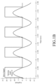
- Prior art systems seek to address this concern by simply driving the MEMS mirrors of two projection systems with a same drive signal as can be seen in FIGS. 1A-1B (here, a 400 Hz drive signal drives two mirrors). However, as can also be seen in FIGS.
- mirror #1 has a resonance frequency of 390 Hz
- mirror #2 has a resonance frequency of 410 Hz
- the opening angles of the mirrors may be unequal when driven with a same drive signal.
- Document EP 1 589 364 A2 discloses an arrangement wherein a scan-beam detection signal provided by horizontal synchronous sensors is input to a drive signal controlling section as a drive period signal related to a drive period of a deflective mirror.
- the drive signal controlling section controls a drive signal such as to establish a predetermined relationship between a phase of a reference signal and a phase of the horizontal synchronous signal, whereby a deflector is allowed to operate in synchronism with the reference signal. Therefore, a latent-image forming position with respect to a sub-scan direction id adjusted by way of the phase adjustment between the reference signal and the horizontal synchronous signal, so that a linear latent image is prevented from deviating with respect to the sub-scan direction Y.
- Document EP 1 589 365 A2 discloses an image forming apparatus including plural exposure units each deflecting a light beam from a light source by means of an oscillation mirror in resonant oscillations and scanning the deflected light beam on a latent image carrier thereby forming a latent image on the latent image carrier, every one of the exposure units assuredly attains an adequate amplitude of the oscillation mirror for ensuring the formation of images of high quality.
- a CPU retrieves resonant frequencies of individual deflectors previously stored in a memory. The CPU calculates an average value of these resonant frequencies and applies a drive command to mirror drivers of the exposure units such as to drive all the deflectors into oscillations at the average value.
- a resonant frequency adjusting section makes adjustment to match the resonant frequencies of the individual deflectors substantially with a drive frequency. This ensures that all the oscillation mirrors attain adequate amplitudes.
- Document US 2009/231721 A1 discloses an image display apparatus having light beam emitting units which emit light beams based on image information and a set operating frequency, and MEMS mirrors which deflect the emitted light beams by deflection operations based on the operating frequency, in correspondence with the right and left eyes.
- Resonance frequency detection units respectively detect the resonance frequencies of the MEMS mirrors.
- a control unit sets the operating frequency of the MEMS mirrors based on the detected resonance frequencies.
- Document US 2018/106903 A1 discloses a distance measuring device executing a collection process that includes driving a MEMS mirror in each of a plurality of sensors and collecting a drive voltage of the MEMS mirror satisfying a given condition, executes a drive frequency determination process that includes determining a drive frequency of the MEMS mirror when measuring distances by the plurality of sensors based on the drive voltage of the MEMS mirror, and executes a control signal generation process that includes generating and transmitting a control signal to the plurality of sensors, the control signal including configuration information specifying the drive frequency as a drive frequency of the MEMS mirror in each of the plurality of sensors, the configuration information including the drive frequency determined by the drive frequency determination process.
- the invention as claimed relates to a method of driving first and second MEMS movable mirrors having the features set forth in claim 1 that follows.
- Advantageous features are recited in claims 2 to 4.
- a projector including a first microelectromechanical (MEMS) mirror, a second MEMS mirror, and a mirror pre-driver configured to generate a pre-drive signal.
- MEMS microelectromechanical
- the pre-drive signal has a frequency that is a frequency at which an opening angle of the first MEMS mirror is equal to an opening angle of the second MEMS mirror, with the frequency of the pre-drive signal being neither a resonance frequency of the first MEMS mirror nor a resonance frequency of the second MEMS mirror.
- a first mirror control circuit is configured to generate a first drive control signal from the pre-drive signal for the first MEMS mirror.
- a first mirror driver is configured to generate a first drive signal for the first MEMS mirror from the first drive control signal.
- a second mirror control circuit is configured to generate a second drive control signal from the pre-drive signal for the second MEMS mirror.
- a second mirror driver is configured to generate a second drive signal for the second MEMS mirror from the second drive control signal.
- the first and second drive control signals are generated by the first and second mirror control circuits so that the first and second drive signals each have a same frequency as the pre-drive signal but each have a different amplitude and phase from one another so as to cause the first and second MEMS mirrors to move at a same frequency, with a same and substantially constant given opening angle, and in phase with one another.
- the frequency at which the opening angle of the first MEMS mirror may be equal to the opening angle of the second MEMS mirror is an average of a resonance frequency of the first MEMS mirror and a resonance frequency of the second MEMS mirror.
- the first and second mirror control circuits generate the first and second drive control signals so that the first and second drive signals are different in amplitude and phase from one another.
- a red-green-blue (RGB) laser source may be configured to project RGB laser beams that impinge upon the first and second MEMS mirrors.
- a VR headset housing has the RGB laser source, the first and second MEMS mirrors, mirror pre-driver, first and second mirror control circuits, and first and second mirror drivers therein.
- a first mirror position sensor is associated with the first MEMS mirror and a second mirror position sensor is associated with the second MEMS mirror.
- a first zero cross detector is associated with the first MEMS mirror and a second zero cross detector is associated with the second MEMS mirror.
- the first and second mirror position sensors may be configured to generate first and second mirror sense signals indicating peak opening angles of the first and second MEMS mirrors.
- the first mirror control circuit generates the first drive control signal as a function of the pre-drive signal, the first mirror sense signal, and detected zero crosses of a first mirror sense signal generated by the first MEMS mirror in response to the first drive signal.
- the second mirror control circuit generates the second drive control signal as a function of the pre-drive signal, the second mirror sense signal, and detected zero crosses of a second mirror sense signal generated by the second MEMS mirror in response to the second drive signal.
- a projector including a first microelectromechanical (MEMS) mirror, a second MEMS mirror, and a mirror pre-driver configured to generate a pre-drive signal.
- the pre-drive signal has a frequency that is a frequency at which an opening angle of the first MEMS mirror is equal to an opening angle of the second MEMS mirror, with the frequency of the pre-drive signal being neither a resonance frequency of the first MEMS mirror nor a resonance frequency of the second MEMS mirror.
- a first mirror control circuit is configured to generate a first drive control signal from the pre-drive signal for the first MEMS mirror.
- a first mirror driver is configured to generate a first drive signal for the first MEMS mirror from the first drive control signal.
- a second mirror control circuit is configured to generate a second drive control signal from the pre-drive signal for the second MEMS mirror.
- a second mirror driver is configured to generate a second drive signal for the second MEMS mirror from the second drive control signal.
- the first and second drive control signals are generated by the first and second mirror control circuits so as to cause the first and second MEMS mirrors to move at a same frequency, with a same and substantially constant given opening angle.
- the frequency at which the opening angle of the first MEMS mirror is equal to the opening angle of the second MEMS mirror may be an average of a resonance frequency of the first MEMS mirror and a resonance frequency of the second MEMS mirror.
- the first and second mirror control circuits generate the first and second drive control signals so that the first and second drive signals are different in amplitude from one another.
- a red-green-blue (RGB) laser source may be configured to project RGB laser beams that impinge upon the first and second MEMS mirrors.
- a VR headset may include a housing having the RGB laser source, the first and second MEMS mirrors, mirror pre-driver, first and second mirror control circuits, and first and second mirror drivers therein.
- a first mirror position sensor is associated with the first MEMS mirror and a second mirror position sensor is associated with the second MEMS mirror.
- the first and second mirror position sensors may be configured to generate first and second mirror sense signals indicating peak opening angles of the first and second MEMS mirrors.
- the first mirror control circuit generates the first drive control signal as a function of the pre-drive signal and the first mirror sense signal.
- the second mirror control circuit generates the second drive control signal as a function of the pre-drive signal and the second mirror sense signal.
- the control circuit includes a mirror pre-driver configured to generate a pre-drive signal, the pre-drive signal having a frequency that is a frequency at which an opening angle of the first movable mirror is equal to an opening angle of the second movable mirror.
- a first mirror control circuit is configured to generate a first drive control signal from the pre-drive signal for the first movable mirror in response to an operating characteristic of the first movable mirror.
- a first mirror driver is configured to generate a first drive signal for the first movable mirror from the first drive control signal.
- a second mirror control circuit is configured to generate a second drive control signal from the pre-drive signal for the second movable mirror in response to an operating characteristic of the second movable mirror.
- a second mirror driver is configured to generate a second drive signal for the second movable mirror from the second drive control signal.
- the first and second drive control signals are generated by the first and second mirror control circuits so that the first and second drive signals each have a same frequency as the pre-drive signal but are different in amplitude from one another so as to cause the first and second movable mirrors to move at a same frequency, with a same and substantially constant given opening angle as one another.
- the frequency at which the opening angle of the first movable mirror is equal to the opening angle of the second movable mirror may be an average of a resonance frequency of the first movable mirror and a resonance frequency of the second movable mirror.
- the operating characteristic of the first movable mirror may be zero crosses of a first mirror sense signal generated by the first movable mirror in response to the first drive signal.
- the operating characteristic of the second movable mirror may be zero crosses of a second mirror sense signal generated by the second movable mirror in response to the second drive signal.
- the first and second drive control signals are generated by the first and second mirror control circuits so that the first and second drive signals are different in phase from one another so as to cause the first and second movable mirrors to move in phase with one another.
- the operating characteristic of the first movable mirror may be a maximum opening angle reached by the first movable mirror.
- the operating characteristic of the second movable mirror may be a maximum opening angle reached by the second movable mirror.
- the first and second drive control signals are generated by the first and second mirror control circuits so that the first and second drive signals are different in amplitude from one another so as to cause the first and second movable mirrors to move with a same and substantially constant given opening angle as one another.
- the invention as claimed relates to a method of driving first and second movable mirrors.
- the method includes generating a pre-drive signal having a frequency that is a frequency at which an opening angle of the first movable mirror is equal to an opening angle of the second movable mirror, generating a first drive control signal from the pre-drive signal for the first movable mirror in response to an operating characteristic of the first movable mirror, generating a first drive signal for the first movable mirror from the first drive control signal, generating a second drive control signal from the pre-drive signal for the second movable mirror in response to an operating characteristic of the second movable mirror, and generating a second drive signal for the second movable mirror from the second drive control signal.
- the first and second drive signals are generated so as to cause the first and second movable mirrors to move at a same frequency, and with a same and substantially constant given opening angle as one another.
- the frequency at which the opening angle of the first movable mirror is equal to the opening angle of the second movable mirror may be an average of a resonance frequency of the first movable mirror and a resonance frequency of the second movable mirror.
- the first and second drive signals are generated to each have a same frequency as the pre-drive signal but be different in amplitude and phase from one another.
- the method may include performing a frequency sweep on a drive signal applied to the first movable mirror while monitoring opening angle of the first movable mirror, and determining a resonance frequency of the first movable mirror to be a frequency of the frequency sweep at which the opening angle of the first movable mirror is at a maximum.
- the method may also include performing a frequency sweep on a drive signal applied to the second movable mirror while monitoring opening angle of the second movable mirror, and determining a resonance frequency of the second movable mirror to be a frequency of the frequency sweep at which the opening angle of the second movable mirror is at a maximum, and calculating an average of the resonance frequency of the first movable mirror and a resonance frequency of the second movable mirror.
- the method may include generating RGB lasers and directing the RGB lasers to impinge upon the first and second movable mirrors.
- any references to “laser”, “laser beam”, “RGB laser beam”, “RGB beam”, “collimated light”, “collimated light beam” or “light” are intended to include any wavelength of light, or a combination of different wavelengths of light.
- a “laser” referred to below may be a single color laser, or may be a unified laser beam of multiple colors of visible light, such as a red-green-blue (RGB) laser beam. Therefore, a “light source”, “laser source”, or other piece of hardware referred to below is to be understood to be capable of producing any form of light as described above. As such, it is to be understood that the terms described above are not intended to be limiting, but are simply used for brevity and for sake of examples.
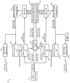
- a dual-projection system 10 for projecting the movement of two red green blue (RGB) laser beams across a target or targets at a rate and resolution sufficient so as to form images visible by the human eye.
- RGB red green blue
- the dual-projection system 10 may be incorporated within virtual reality or augmented reality headsets of any sort, including but not limited to goggles, visors, and glasses.
- the dual-projection system 10 includes first and second microelectromechanical (MEMS) mirrors 11a, 11b that are formed, sized, and dimensioned as typical MEMS mirrors produced by STMicroelectronics (trademark), although it is to be understood that other MEMS mirrors may be used.
- MEMS mirrors 11a, 11b may be uniaxial or biaxial resonance mirrors
- a projection engine 16 receives image data 27 from an external source, processes the image data, and then generates first and second beam control signals 26a, 26b respectively for the first and second RGB laser apparatuses 17a, 17b to cause the first and second RGB laser apparatuses 17a, 17b to produce first and second RGB lasers 18a, 18b that are directed toward and impinge upon the MEMS mirrors 11a, 11b.
- the beam control signals 26a, 26b serve to cause the laser apparatuses 17a, 17b to appropriately generate and modulate the intensity of RGB lasers 18a, 18b so that when the RGB lasers 18a, 18b are reflected by the MEMS mirrors 11a, 11b across display area targets in a suitable pattern, the images contained within the image data 27 are reproduced in a format visible to the human eye.
- the aforementioned display area targets may have flat or curved surfaces.
- a mirror pre-driver 12 generates a pre-drive signal 21 that has a frequency equal to that at which an opening angle of the first and second mirrors is equal (which, in some instances, may be an average of the resonance frequencies of the MEMS mirrors 11a, 11b -- that is, the frequency of the pre-drive signal 21 may be equal to 0.5*(Resonance Frequency of MEMS Mirror 11a + Resonance Frequency of MEMS mirror 11b) -- or may be the meeting point of the gain transfer function of the MEMS mirror 11a and MEMS mirror 11b, or other suitable frequency).
- the goal of the frequency for the pre-drive signal 21 is that produced drive signals 22a, 22b for the MEMS mirrors 11a, 11b have enough drive energy to open both the MEMS mirrors 11a, 11b to a same desired opening angle.
- the frequency of the pre-drive signal 21 matches neither the resonance frequency of MEMS mirror 11a nor the resonance frequency of MEMS mirror 11b, since these resonance frequencies will not be equal due to manufacturing variation.
- the mirror drivers 13a, 13b each receive the pre-drive signal 21 and generate from it respective drive signals 22a, 22b for the MEMS mirrors 11a, 11b. Note that these drive signals 22a, 22b may take any periodic shape (e.g., square wave, pulsed signal, sine wave, cosine wave, etc.) and both have the same frequency of that of the pre-drive signal 21 and therefore the same frequency as one another.
- the mirror controllers 14a, 14b will adjust the amplitudes of the drive signals 22a, 22b through issuing suitable instructions to the mirror drivers 13a, 13b in the form of drive control signals 24a, 24b.
- the MEMS mirrors 11a, 11b In response to the drive signals 22a, 22b applied to the MEMS mirrors 11a, 11b, the MEMS mirrors 11a, 11b produce mirror sense signals 23a, 23b.
- Mirror position sensors 15c, 15d (which may be, for example, piezoresistive sensors) are respectively associated with the MEMS mirrors 11a, 11b and generate mirror sense signals 23a, 23b indicating the current opening angles of the MEMS mirrors 11a, 11b. From the mirror sense signals 23a, 23b, the mirror controllers 14a, 14b determine the peak opening angles of the MEMS mirrors 11a, 11b, and then modify the drive control signals 24a, 24b to the mirror drivers 13a, 13b in such a fashion so as to cause the MEMS mirrors 11a, 11b to operate with a same peak opening angle.
- the mirror controllers 14a, 14b generate drive control signals 24a, 24b for the mirror drivers 13a, 13b that cause the mirror drivers 13a, 13b to adjust the amplitudes of the drive signals 22a, 22b separately from one another, with the aim of ensuring that the MEMS mirrors 11a, 11b maintain constant and equal opening angles.
- the drive control signals 24a, 24b do not cause the mirror drivers 13a, 13b to adjust the frequency of the drive signals 22a, 22b, and that the frequency of the drive signals 22a, 22b remains equal to that of the pre-drive signal 21.
- the result of this adjustment may be that the drive signals 22a, 22b have different amplitudes so as to produce a same maximum opening angle of the MEMS mirrors 11a, 11b.
- the end result is that the MEMS mirrors 11a, 11b move or oscillate at the same frequency and each maintain a constant opening angle, with the opening angles of the MEMS mirrors 11a, 11b being equal to one another.
- Zero cross detectors 15a, 15b respectively receive the mirror sense signals 23a, 23b and detect zero crosses of the mirror sense signals 23a, 23b, and produce zero cross detection flags 25a, 25b at each detected zero cross.
- the projection engine 16 uses the zero cross detect signals 25a, 25b and/or the mirror sense signals 23a, 23b to synchronize projection for generating the beam control signals 26a, 26b so that the RGB laser apparatuses 17a, 17b properly modulate the RGB lasers 18a, 18b in coordination with the movement of the MEMS mirrors 11a, 11b such that the proper modulation for the RGB laser beams 18a, 18b is present at each spot of the targets over which the RGB laser beams 18a, 18b scan.
- the movements of the MEMS mirrors 11a, 11b it is desired for the movements of the MEMS mirrors 11a, 11b to be in phase with one another.
- the zero crosses detected by the zero cross detectors 15a, 15b are passed to the mirror controllers 14a, 14b.
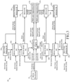
- the mirror controllers 14a, 14b can adjust the phase of the drive control signals 24a, 24b they respectively produce (which in turn adjusts the phase of the drive signals 22a, 22b) until the zero crosses of the MEMS mirrors 11a, 11b occur simultaneously.
- the drive control signals 24a, 24b may end up being out of phase with each other in order to produce simultaneous zero crosses of the MEMS mirrors 11a, 11b.
- only one of the mirror controllers 14a, 14b adjusts the phase of its respective drive control signals 24a, 24b based upon the difference in time between the zero crosses of the MEMS mirrors 11a, 11b detected by the zero cross detectors 15a, 15b, so that the zero crosses of the MEMS mirrors 11a, 11b occur simultaneously.
- any suitable technique may be used to change the phase of the drive control signals 24a, 24b.
- the mirror controllers 14a, 14b may use a digital delay to change the phase of the drive control signals 24a, 24b, or may change a counter value used in generating the drive control signals 24a, 24b.
- FIG. 4 The effect of this shift in the phase of a drive control signal on a drive signal can be seen in FIG. 4 .
- the previous waveform of the drive signal is shown in dashed lines, while the current waveform of the drive signal is shown in solid lines. It can be seen that phase of the previous waveform of the drive signal has been adjusted to produce the current waveform of the drive signal.
- Any suitable technique may be used to determine the resonance frequencies of the MEMS mirrors 11a, 11b of both FIG. 2 and FIG. 3 . This can be performed as a production test. Alternatively, this can be performed in a calibration phase of operation in which the mirror drivers 13a, 13b perform a frequency sweep of the drive signals 22a, 22b while the opening angles of the MEMS mirrors 11a, 11b are monitors. The frequency of the drive signals 22a, 22b at which each MEMS mirror 11a, 11b is at its maximum opening angle is the resonance frequency for that MEMS mirror.
- circuits and techniques are not limited to the control of two MEMS mirrors but instead may be applied to any number of MEMS mirrors, with the pre-drive signal being an average of the resonance frequencies of all MEMS mirrors that it is desired to control.
Landscapes
- Physics & Mathematics (AREA)
- General Physics & Mathematics (AREA)
- Optics & Photonics (AREA)
- Engineering & Computer Science (AREA)
- Multimedia (AREA)
- Signal Processing (AREA)
- Mechanical Optical Scanning Systems (AREA)
- Mechanical Light Control Or Optical Switches (AREA)
Description
- This application is related to the field of laser projection systems, and in particular, to control circuits and techniques for driving two or more movable resonant mirrors at a same frequency.
- Certain laser scanning projection devices such as projectors and the like often employ a collimated laser beam that scans across a flat or curved surface in a straight line path. These devices employ projection systems incorporating tilting mirrors to deflect the collimated laser beam to perform the scanning. These tilting mirrors may be, or may include, Micro Electro Mechanical Systems ("MEMS") devices. The actuation of mirrors used in MEMS devices, referred to herein as MEMS mirrors, can be via the electromagnetic, electrostatic, piezoelectric, and thermoelectric effects, depending on application.
- One type of common resonant MEMS mirror includes a stator and a rotor, with the rotor or structures carried by the rotor being reflective. The stator and/or rotor are driven with a drive signal which results in the rotor oscillating at resonance with respect to the stator, thereby changing the angle of reflectance of an incident light beam on the rotor. By oscillating the rotor between two orientations at resonance, an opening angle of the mirror is defined, and scanning of the light beam across the flat surface is accomplished.
- A particularly challenging application for projectors exists in their incorporation into virtual reality or augmented reality headsets, as such applications typically involve the use of a separate projection system for each eye. The use of a separate projection system for each eye means that it is desired for such projection systems to move their laser beams at a same frequency so as to reduce visual strain on a user, while maintaining the same opening angle as one another to produce equally sized images. Prior art systems seek to address this concern by simply driving the MEMS mirrors of two projection systems with a same drive signal as can be seen in
FIGS. 1A-1B (here, a 400 Hz drive signal drives two mirrors). However, as can also be seen inFIGS. 1A-1B , this will not result in the MEMS mirrors having the same opening angle due to manufacturing variations in the MEMS mirrors --mirror # 1 has a resonance frequency of 390 Hz, whilemirror # 2 has a resonance frequency of 410 Hz, with the result being that the phases ofmirror # 1 andmirror # 2 are not aligned. In addition to this phase misalignment, the opening angles of the mirrors may be unequal when driven with a same drive signal. - Since movement of the MEMS mirrors of the separate projection systems within such a headset at a same frequency, in phase, and at a same opening angle is most desirable, further development into this area is therefore needed.
-
Document EP 1 589 364 A2 discloses an arrangement wherein a scan-beam detection signal provided by horizontal synchronous sensors is input to a drive signal controlling section as a drive period signal related to a drive period of a deflective mirror. The drive signal controlling section controls a drive signal such as to establish a predetermined relationship between a phase of a reference signal and a phase of the horizontal synchronous signal, whereby a deflector is allowed to operate in synchronism with the reference signal. Therefore, a latent-image forming position with respect to a sub-scan direction id adjusted by way of the phase adjustment between the reference signal and the horizontal synchronous signal, so that a linear latent image is prevented from deviating with respect to the sub-scan direction Y. -
Document EP 1 589 365 A2 discloses an image forming apparatus including plural exposure units each deflecting a light beam from a light source by means of an oscillation mirror in resonant oscillations and scanning the deflected light beam on a latent image carrier thereby forming a latent image on the latent image carrier, every one of the exposure units assuredly attains an adequate amplitude of the oscillation mirror for ensuring the formation of images of high quality. More specifically, a CPU retrieves resonant frequencies of individual deflectors previously stored in a memory. The CPU calculates an average value of these resonant frequencies and applies a drive command to mirror drivers of the exposure units such as to drive all the deflectors into oscillations at the average value. Alternatively, a resonant frequency adjusting section makes adjustment to match the resonant frequencies of the individual deflectors substantially with a drive frequency. This ensures that all the oscillation mirrors attain adequate amplitudes. - Document
US 2009/231721 A1 discloses an image display apparatus having light beam emitting units which emit light beams based on image information and a set operating frequency, and MEMS mirrors which deflect the emitted light beams by deflection operations based on the operating frequency, in correspondence with the right and left eyes. Resonance frequency detection units respectively detect the resonance frequencies of the MEMS mirrors. A control unit sets the operating frequency of the MEMS mirrors based on the detected resonance frequencies. - Document
US 2018/106903 A1 discloses a distance measuring device executing a collection process that includes driving a MEMS mirror in each of a plurality of sensors and collecting a drive voltage of the MEMS mirror satisfying a given condition, executes a drive frequency determination process that includes determining a drive frequency of the MEMS mirror when measuring distances by the plurality of sensors based on the drive voltage of the MEMS mirror, and executes a control signal generation process that includes generating and transmitting a control signal to the plurality of sensors, the control signal including configuration information specifying the drive frequency as a drive frequency of the MEMS mirror in each of the plurality of sensors, the configuration information including the drive frequency determined by the drive frequency determination process. - The invention as claimed relates to a method of driving first and second MEMS movable mirrors having the features set forth in
claim 1 that follows. Advantageous features are recited inclaims 2 to 4. - Disclosed herein is a projector including a first microelectromechanical (MEMS) mirror, a second MEMS mirror, and a mirror pre-driver configured to generate a pre-drive signal.
- While beneficial in understanding the invention, various features disclosed in connection with such a projector are not part of the invention as claimed insofar as they are not encompassed by the wording of the claims.
- The pre-drive signal has a frequency that is a frequency at which an opening angle of the first MEMS mirror is equal to an opening angle of the second MEMS mirror, with the frequency of the pre-drive signal being neither a resonance frequency of the first MEMS mirror nor a resonance frequency of the second MEMS mirror. A first mirror control circuit is configured to generate a first drive control signal from the pre-drive signal for the first MEMS mirror. A first mirror driver is configured to generate a first drive signal for the first MEMS mirror from the first drive control signal. A second mirror control circuit is configured to generate a second drive control signal from the pre-drive signal for the second MEMS mirror. A second mirror driver is configured to generate a second drive signal for the second MEMS mirror from the second drive control signal. The first and second drive control signals are generated by the first and second mirror control circuits so that the first and second drive signals each have a same frequency as the pre-drive signal but each have a different amplitude and phase from one another so as to cause the first and second MEMS mirrors to move at a same frequency, with a same and substantially constant given opening angle, and in phase with one another.
- The frequency at which the opening angle of the first MEMS mirror may be equal to the opening angle of the second MEMS mirror is an average of a resonance frequency of the first MEMS mirror and a resonance frequency of the second MEMS mirror.
- The first and second mirror control circuits generate the first and second drive control signals so that the first and second drive signals are different in amplitude and phase from one another.
- A red-green-blue (RGB) laser source may be configured to project RGB laser beams that impinge upon the first and second MEMS mirrors. A VR headset housing has the RGB laser source, the first and second MEMS mirrors, mirror pre-driver, first and second mirror control circuits, and first and second mirror drivers therein.
- A first mirror position sensor is associated with the first MEMS mirror and a second mirror position sensor is associated with the second MEMS mirror. A first zero cross detector is associated with the first MEMS mirror and a second zero cross detector is associated with the second MEMS mirror. The first and second mirror position sensors may be configured to generate first and second mirror sense signals indicating peak opening angles of the first and second MEMS mirrors. The first mirror control circuit generates the first drive control signal as a function of the pre-drive signal, the first mirror sense signal, and detected zero crosses of a first mirror sense signal generated by the first MEMS mirror in response to the first drive signal. The second mirror control circuit generates the second drive control signal as a function of the pre-drive signal, the second mirror sense signal, and detected zero crosses of a second mirror sense signal generated by the second MEMS mirror in response to the second drive signal.
- Also disclosed herein is a projector including a first microelectromechanical (MEMS) mirror, a second MEMS mirror, and a mirror pre-driver configured to generate a pre-drive signal. The pre-drive signal has a frequency that is a frequency at which an opening angle of the first MEMS mirror is equal to an opening angle of the second MEMS mirror, with the frequency of the pre-drive signal being neither a resonance frequency of the first MEMS mirror nor a resonance frequency of the second MEMS mirror. A first mirror control circuit is configured to generate a first drive control signal from the pre-drive signal for the first MEMS mirror. A first mirror driver is configured to generate a first drive signal for the first MEMS mirror from the first drive control signal. A second mirror control circuit is configured to generate a second drive control signal from the pre-drive signal for the second MEMS mirror. A second mirror driver is configured to generate a second drive signal for the second MEMS mirror from the second drive control signal. The first and second drive control signals are generated by the first and second mirror control circuits so as to cause the first and second MEMS mirrors to move at a same frequency, with a same and substantially constant given opening angle.
- The frequency at which the opening angle of the first MEMS mirror is equal to the opening angle of the second MEMS mirror may be an average of a resonance frequency of the first MEMS mirror and a resonance frequency of the second MEMS mirror.
- The first and second mirror control circuits generate the first and second drive control signals so that the first and second drive signals are different in amplitude from one another.
- A red-green-blue (RGB) laser source may be configured to project RGB laser beams that impinge upon the first and second MEMS mirrors. A VR headset may include a housing having the RGB laser source, the first and second MEMS mirrors, mirror pre-driver, first and second mirror control circuits, and first and second mirror drivers therein.
- A first mirror position sensor is associated with the first MEMS mirror and a second mirror position sensor is associated with the second MEMS mirror. The first and second mirror position sensors may be configured to generate first and second mirror sense signals indicating peak opening angles of the first and second MEMS mirrors. The first mirror control circuit generates the first drive control signal as a function of the pre-drive signal and the first mirror sense signal. The second mirror control circuit generates the second drive control signal as a function of the pre-drive signal and the second mirror sense signal.
- Also disclosed herein is a control circuit for driving first and second movable mirrors. The control circuit includes a mirror pre-driver configured to generate a pre-drive signal, the pre-drive signal having a frequency that is a frequency at which an opening angle of the first movable mirror is equal to an opening angle of the second movable mirror. A first mirror control circuit is configured to generate a first drive control signal from the pre-drive signal for the first movable mirror in response to an operating characteristic of the first movable mirror. A first mirror driver is configured to generate a first drive signal for the first movable mirror from the first drive control signal. A second mirror control circuit is configured to generate a second drive control signal from the pre-drive signal for the second movable mirror in response to an operating characteristic of the second movable mirror. A second mirror driver is configured to generate a second drive signal for the second movable mirror from the second drive control signal. The first and second drive control signals are generated by the first and second mirror control circuits so that the first and second drive signals each have a same frequency as the pre-drive signal but are different in amplitude from one another so as to cause the first and second movable mirrors to move at a same frequency, with a same and substantially constant given opening angle as one another.
- The frequency at which the opening angle of the first movable mirror is equal to the opening angle of the second movable mirror may be an average of a resonance frequency of the first movable mirror and a resonance frequency of the second movable mirror.
- The operating characteristic of the first movable mirror may be zero crosses of a first mirror sense signal generated by the first movable mirror in response to the first drive signal. The operating characteristic of the second movable mirror may be zero crosses of a second mirror sense signal generated by the second movable mirror in response to the second drive signal. The first and second drive control signals are generated by the first and second mirror control circuits so that the first and second drive signals are different in phase from one another so as to cause the first and second movable mirrors to move in phase with one another.
- The operating characteristic of the first movable mirror may be a maximum opening angle reached by the first movable mirror. The operating characteristic of the second movable mirror may be a maximum opening angle reached by the second movable mirror. The first and second drive control signals are generated by the first and second mirror control circuits so that the first and second drive signals are different in amplitude from one another so as to cause the first and second movable mirrors to move with a same and substantially constant given opening angle as one another.
- The invention as claimed relates to a method of driving first and second movable mirrors. The method includes generating a pre-drive signal having a frequency that is a frequency at which an opening angle of the first movable mirror is equal to an opening angle of the second movable mirror, generating a first drive control signal from the pre-drive signal for the first movable mirror in response to an operating characteristic of the first movable mirror, generating a first drive signal for the first movable mirror from the first drive control signal, generating a second drive control signal from the pre-drive signal for the second movable mirror in response to an operating characteristic of the second movable mirror, and generating a second drive signal for the second movable mirror from the second drive control signal. The first and second drive signals are generated so as to cause the first and second movable mirrors to move at a same frequency, and with a same and substantially constant given opening angle as one another.
- The frequency at which the opening angle of the first movable mirror is equal to the opening angle of the second movable mirror may be an average of a resonance frequency of the first movable mirror and a resonance frequency of the second movable mirror.
- The first and second drive signals are generated to each have a same frequency as the pre-drive signal but be different in amplitude and phase from one another.
- Prior to generating the pre-drive signal, the method may include performing a frequency sweep on a drive signal applied to the first movable mirror while monitoring opening angle of the first movable mirror, and determining a resonance frequency of the first movable mirror to be a frequency of the frequency sweep at which the opening angle of the first movable mirror is at a maximum. Prior to generating the pre-drive signal, the method may also include performing a frequency sweep on a drive signal applied to the second movable mirror while monitoring opening angle of the second movable mirror, and determining a resonance frequency of the second movable mirror to be a frequency of the frequency sweep at which the opening angle of the second movable mirror is at a maximum, and calculating an average of the resonance frequency of the first movable mirror and a resonance frequency of the second movable mirror.
- The method may include generating RGB lasers and directing the RGB lasers to impinge upon the first and second movable mirrors.
-
-
FIGS. 1A-1B are graphs showing that in prior art systems that drive two mirrors at a frequency that is the average of the resonance frequency of both mirrors, the opening angles of the mirrors are out of phase with one another. -
FIG. 2 is a block diagram of a first dual-projection system in accordance with this disclosure in which there are two mirrors operated at a same frequency. -
FIG. 3 is a block diagram of a second dual-projection system in accordance with this disclosure in which there are two mirrors operated at a same frequency. -
FIG. 4 is a graph showing adjustment of phase of a drive signal for a MEMS mirror, such as may be performed by the dual-projection system ofFIG. 3 . - The following disclosure enables a person skilled in the art to make and use the subject matter disclosed herein. The general principles described herein may be applied to embodiments and applications other than those detailed above without departing from the extent of protection as determined by the claims (consistent with the principles and features disclosed or suggested herein).
- It should be understood that in the descriptions below, any references to "laser", "laser beam", "RGB laser beam", "RGB beam", "collimated light", "collimated light beam" or "light" are intended to include any wavelength of light, or a combination of different wavelengths of light. For example, a "laser" referred to below may be a single color laser, or may be a unified laser beam of multiple colors of visible light, such as a red-green-blue (RGB) laser beam. Therefore, a "light source", "laser source", or other piece of hardware referred to below is to be understood to be capable of producing any form of light as described above. As such, it is to be understood that the terms described above are not intended to be limiting, but are simply used for brevity and for sake of examples.
- Now described with reference to
FIG. 2 is a dual-projection system 10 for projecting the movement of two red green blue (RGB) laser beams across a target or targets at a rate and resolution sufficient so as to form images visible by the human eye. In particular, two images are formed, one for each eye. The dual-projection system 10 may be incorporated within virtual reality or augmented reality headsets of any sort, including but not limited to goggles, visors, and glasses. - The dual-
projection system 10 includes first and second microelectromechanical (MEMS) mirrors 11a, 11b that are formed, sized, and dimensioned as typical MEMS mirrors produced by STMicroelectronics (trademark), although it is to be understood that other MEMS mirrors may be used. The MEMS mirrors 11a, 11b may be uniaxial or biaxial resonance mirrors - A
projection engine 16 receivesimage data 27 from an external source, processes the image data, and then generates first and secondbeam control signals RGB laser apparatuses RGB laser apparatuses second RGB lasers beam control signals laser apparatuses RGB lasers RGB lasers image data 27 are reproduced in a format visible to the human eye. The aforementioned display area targets may have flat or curved surfaces. - The driving of the movement of the MEMS mirrors 11a, 11b is now described. A
mirror pre-driver 12 generates apre-drive signal 21 that has a frequency equal to that at which an opening angle of the first and second mirrors is equal (which, in some instances, may be an average of the resonance frequencies of the MEMS mirrors 11a, 11b -- that is, the frequency of thepre-drive signal 21 may be equal to 0.5*(Resonance Frequency ofMEMS Mirror 11a + Resonance Frequency ofMEMS mirror 11b) -- or may be the meeting point of the gain transfer function of theMEMS mirror 11a andMEMS mirror 11b, or other suitable frequency). The goal of the frequency for thepre-drive signal 21 is that produceddrive signals - The frequency of the
pre-drive signal 21 matches neither the resonance frequency ofMEMS mirror 11a nor the resonance frequency ofMEMS mirror 11b, since these resonance frequencies will not be equal due to manufacturing variation. Themirror drivers pre-drive signal 21 and generate from itrespective drive signals drive signals pre-drive signal 21 and therefore the same frequency as one another. As will be explained, however, on the basis of feedback, themirror controllers drive signals mirror drivers drive control signals - In response to the
drive signals mirror sense signals -
Mirror position sensors mirror sense signals mirror sense signals mirror controllers drive control signals mirror drivers - Therefore, overall, the
mirror controllers drive control signals mirror drivers mirror drivers drive signals drive control signals mirror drivers drive signals drive signals pre-drive signal 21. Also note that the result of this adjustment may be that thedrive signals - Zero
cross detectors mirror sense signals mirror sense signals cross detection flags projection engine 16 uses the zero cross detectsignals mirror sense signals beam control signals RGB laser apparatuses RGB lasers RGB laser beams RGB laser beams - In some cases, it is desired for the movements of the MEMS mirrors 11a, 11b to be in phase with one another. In this case, as shown in the dual-projection system 10' of
FIG. 3 , the zero crosses detected by the zerocross detectors mirror controllers MEMS mirror mirror controllers drive control signals drive signals drive control signals - It should be appreciated that as an alternative to the above, in some applications, only one of the
mirror controllers drive control signals cross detectors - Regarding the effectuation of the phase changes of the
drive control signals drive control signals mirror controllers drive control signals drive control signals - The effect of this shift in the phase of a drive control signal on a drive signal can be seen in
FIG. 4 . Here, the previous waveform of the drive signal is shown in dashed lines, while the current waveform of the drive signal is shown in solid lines. It can be seen that phase of the previous waveform of the drive signal has been adjusted to produce the current waveform of the drive signal. - Other techniques usable for opening angle and/or maintenance of the
drive signals U.S. Pat. Pub. 2018/0356627 ,U.S. Pat. Pub. 2018/0348506 ,U.S. Pat. Pub. 2018/0321483 ,U.S. Pat. Pub. 2018/0067303 ,U.S. Pat. Pub. 2018/0024351 ,U.S. Pat. Pub. 2017/0307873 ,U.S. Pat. Pub. 2017/0131540 , andU.S. Pat. Pub. 16/032,634 . Those of skill in the art will understand how to adapt descriptions in these references of using opening angle control to maintain the mirrors at resonance to instead be to maintain the mirrors at the maximal opening angle possible for the frequency of the pre-drive signal used. - Any suitable technique may be used to determine the resonance frequencies of the MEMS mirrors 11a, 11b of both
FIG. 2 andFIG. 3 . This can be performed as a production test. Alternatively, this can be performed in a calibration phase of operation in which themirror drivers drive signals drive signals MEMS mirror - It should be understood that the above circuits and techniques are not limited to the control of two MEMS mirrors but instead may be applied to any number of MEMS mirrors, with the pre-drive signal being an average of the resonance frequencies of all MEMS mirrors that it is desired to control.
- While the disclosure has been described with respect to a limited number of embodiments, those skilled in the art, having benefit of this disclosure, will appreciate that other embodiments can be envisioned that do not depart from the scope of the disclosure as claimed. Accordingly, the scope of the disclosure shall be limited only by the attached claims.
Claims (4)
- A method of driving first and second MEMS movable mirrors (11a, 11b), having respective opening angles, the method comprising:generating a pre-drive signal (21) having a frequency that is a frequency at which an opening angle of the first movable mirror (11a) is equal to an opening angle of the second MEMS mirror (1 1b), wherein the frequency of the pre-drive signal (21) is neither a resonance frequency of the first MEMS mirror (11a) nor a resonance frequency of the second MEMS mirror (11b);generating a first drive control signal (24a) from the pre-drive signal (21) for the first movable mirror (1 1a);generating a first drive signal (22a) for the first movable mirror (11a) from the first drive control signal (24a);generating a second drive control signal (24b) from the pre-drive signal (21) for the second movable mirror (11b); andgenerating a second drive signal (22b) for the second movable mirror (11b) from the second drive control signal (24b);wherein the first and second drive signals (22a,22b) are generated so as to cause the first and second movable mirrors (11a,11b) to move at a same frequency, with a same and substantially constant given opening angle, and the first and second drive signals (22a,22b) are generated to each have a same frequency as the pre-drive signal (21) but be different in amplitude and phase from one another,wherein the method comprises:generating, via mirror position sensors (15c, 15d) respectively associated with the MEMS mirrors (11a, 11b), mirror sense signals (23a, 23b) indicating the current opening angles of the MEMS mirrors (11a, 11b), with zero cross detectors (15a, 15b) respectively receiving the mirror sense signals (23a, 23b), detecting zero crosses of the mirror sense signals (23a, 23b) and producing zero cross detection flags (25a, 25b) at each detected zero cross,generating, via mirror controllers (14a, 14b) said drive control signals (24a, 24b) for mirror drivers (13a, 13b) that cause the mirror drivers (13a, 13b) to adjust the amplitudes of the drive signals (22a, 22b) separately from one another, with the aim of ensuring that the MEMS mirrors (11a, 11b) maintain constant and equal opening angles, andsaid mirror controllers (14a, 14b) determining the difference in time between the zero crosses of each MEMS mirror (11a, 11b) and adjusting the phase of the drive control signals (24a, 24b) they respectively produce, which in turn adjusts the phase of the drive signals (22a, 22b) until the zero crosses of the MEMS mirrors (11a, 11b) occur simultaneously.
- The method of claim 1, further comprising, prior to generating the pre-drive signal:performing a frequency sweep on a drive signal applied to the first movable mirror (11a) while monitoring opening angle of the first movable mirror (11a), and determining the resonance frequency of the first movable mirror (11a) to be a frequency of the frequency sweep at which the opening angle of the first movable mirror (11a) is at a maximum;performing a frequency sweep on a drive signal applied to the second movable mirror (11b) while monitoring opening angle of the second movable mirror (1 1b), and determining the resonance frequency of the second movable mirror (11b) to be a frequency of the frequency sweep at which the opening angle of the second movable mirror (11b) is at a maximum; andcalculating the frequency at which the opening angle of the first MEMS mirror (11a) is equal to the opening angle of the second MEMS mirror (11b) as an average of the resonance frequency of the first movable mirror (11a) and the resonance frequency of the second movable mirror (11b).
- The method of claim 1 or claim 2, further comprising generating RGB lasers and directing the RGB lasers to impinge upon the first and second movable mirrors.
- The method of claim 1, wherein the pre-drive signal (21) has a frequency equal to the meeting point of the gain transfer function of the MEMS mirror (11a) and the MEMS mirror (11b).
Applications Claiming Priority (1)
| Application Number | Priority Date | Filing Date | Title |
|---|---|---|---|
| US16/540,557 US11474425B2 (en) | 2019-08-14 | 2019-08-14 | Driving multiple resonance MEMS mirrors with a single frequency |
Publications (2)
| Publication Number | Publication Date |
|---|---|
| EP3779558A1 EP3779558A1 (en) | 2021-02-17 |
| EP3779558B1 true EP3779558B1 (en) | 2024-08-28 |
Family
ID=71846241
Family Applications (1)
| Application Number | Title | Priority Date | Filing Date |
|---|---|---|---|
| EP20188304.8A Active EP3779558B1 (en) | 2019-08-14 | 2020-07-29 | Driving multiple resonance mems mirrors with a single frequency |
Country Status (3)
| Country | Link |
|---|---|
| US (1) | US11474425B2 (en) |
| EP (1) | EP3779558B1 (en) |
| CN (2) | CN112399159B (en) |
Families Citing this family (2)
| Publication number | Priority date | Publication date | Assignee | Title |
|---|---|---|---|---|
| US11474425B2 (en) * | 2019-08-14 | 2022-10-18 | Stmicroelectronics Ltd | Driving multiple resonance MEMS mirrors with a single frequency |
| CN115016114B (en) * | 2021-03-03 | 2024-06-14 | 中国科学院苏州纳米技术与纳米仿生研究所 | Laser scanning system and method |
Citations (1)
| Publication number | Priority date | Publication date | Assignee | Title |
|---|---|---|---|---|
| US20180106903A1 (en) * | 2016-10-14 | 2018-04-19 | Fujitsu Limited | Distance measuring device, distance measuring method, and non-transitory computer-readable storage medium |
Family Cites Families (17)
| Publication number | Priority date | Publication date | Assignee | Title |
|---|---|---|---|---|
| JP2005305770A (en) | 2004-04-20 | 2005-11-04 | Seiko Epson Corp | Image forming apparatus and image forming method |
| US7557822B2 (en) | 2004-04-20 | 2009-07-07 | Seiko Epson Corporation | Apparatus for and method of forming image using oscillation mirror |
| US7639274B2 (en) | 2004-04-20 | 2009-12-29 | Seiko Epson Corporation | Image forming apparatus with exposure units using oscillation mirrors and method for controlling drive frequencies of the oscillation mirrors |
| US7233343B2 (en) | 2004-11-24 | 2007-06-19 | Texas Instruments Incorporated | Serial printing with multiple torsional hinged MEMS mirrors |
| JP5012463B2 (en) | 2007-12-03 | 2012-08-29 | セイコーエプソン株式会社 | Scanning image display system and scanning image display device |
| JP5393043B2 (en) | 2008-03-14 | 2014-01-22 | キヤノン株式会社 | Image display device and image display method |
| KR20100078688A (en) | 2008-12-30 | 2010-07-08 | 송혁규 | Apparatus and method for dislpaying for projection |
| JP5177077B2 (en) | 2009-05-26 | 2013-04-03 | 富士通株式会社 | Optical switch and optical switch control method |
| JP2014013314A (en) | 2012-07-04 | 2014-01-23 | Sumitomo Electric Ind Ltd | Wavelength selection switch and method of controlling the same |
| US10246742B2 (en) * | 2015-05-20 | 2019-04-02 | Quantum-Si Incorporated | Pulsed laser and bioanalytic system |
| US9740002B2 (en) | 2015-11-10 | 2017-08-22 | Stmicroelectronics Ltd | Controlling opening angle of a resonating mirror |
| US9810902B1 (en) | 2016-06-24 | 2017-11-07 | Stmicroelectronics Ltd | Opening angle measurement of an oscillating MEMS mirror |
| US10228555B2 (en) | 2016-09-06 | 2019-03-12 | Stmicroelectronics Ltd | Resonance MEMS mirror control system |
| US10261312B2 (en) | 2017-05-08 | 2019-04-16 | Stmicroelectronics Ltd | Opening angle stabilization of micromirrors through current drive control |
| US10365474B2 (en) | 2017-06-05 | 2019-07-30 | Stmicroelectronics Ltd | Phase error measurement for oscillating mirrors |
| US10401616B2 (en) | 2017-06-08 | 2019-09-03 | Stmicroelectronics Ltd. | Amplitude control during start-up of resonating mirror |
| US11474425B2 (en) * | 2019-08-14 | 2022-10-18 | Stmicroelectronics Ltd | Driving multiple resonance MEMS mirrors with a single frequency |
-
2019
- 2019-08-14 US US16/540,557 patent/US11474425B2/en active Active
-
2020
- 2020-07-29 EP EP20188304.8A patent/EP3779558B1/en active Active
- 2020-08-13 CN CN202010814761.6A patent/CN112399159B/en active Active
- 2020-08-13 CN CN202021686254.0U patent/CN212752483U/en not_active Withdrawn - After Issue
Patent Citations (1)
| Publication number | Priority date | Publication date | Assignee | Title |
|---|---|---|---|---|
| US20180106903A1 (en) * | 2016-10-14 | 2018-04-19 | Fujitsu Limited | Distance measuring device, distance measuring method, and non-transitory computer-readable storage medium |
Also Published As
| Publication number | Publication date |
|---|---|
| US11474425B2 (en) | 2022-10-18 |
| EP3779558A1 (en) | 2021-02-17 |
| US20210048737A1 (en) | 2021-02-18 |
| CN112399159B (en) | 2023-06-30 |
| CN112399159A (en) | 2021-02-23 |
| CN212752483U (en) | 2021-03-19 |
Similar Documents
| Publication | Publication Date | Title |
|---|---|---|
| US8569727B2 (en) | Light beam scanning image projection apparatus | |
| US8963898B2 (en) | Control device for a micromirror, method for controlling a micromirror and image projection system | |
| KR101713366B1 (en) | A Method and Device for Projecting an Image | |
| US20160330418A1 (en) | Image projection device and adjustment method | |
| EP2782343B1 (en) | Image display device | |
| EP3121648B1 (en) | Laser projector | |
| US9251730B2 (en) | Image display apparatus and image scanning apparatus | |
| US9075246B2 (en) | Image display device having laser light scanning with a variation in scanning speed | |
| EP2818909A1 (en) | Image display device and mirror drive method therefor | |
| EP2246727A1 (en) | Laser Projector | |
| US20140063472A1 (en) | Laser Scanning Projection Apparatus with Phase Detection and Compensation | |
| US10187620B2 (en) | Display device | |
| US10261312B2 (en) | Opening angle stabilization of micromirrors through current drive control | |
| JP2024028338A (en) | scanning device | |
| JP4929738B2 (en) | Optical scanning device, optical scanning device control method, and image display device | |
| EP3779558A1 (en) | Driving multiple resonance mems mirrors with a single frequency | |
| US20120327373A1 (en) | Scan-type image display device | |
| JP2014186068A (en) | Image display device | |
| JP2003005110A (en) | Two-dimensional optical scanning device | |
| JP2006133643A (en) | Optical scanning device, optical scanning method, and image display device | |
| US12468147B2 (en) | Multi-beam laser beam scanner in a picture generation unit | |
| WO2011108395A1 (en) | Optical scanning device and image display device provided with the same | |
| JP2021033011A (en) | Optical scanner, optical scanning method and program | |
| JP2020194116A (en) | Laser scanning type video device | |
| US12235180B2 (en) | Phase alignment system and method of oscillating mirror |
Legal Events
| Date | Code | Title | Description |
|---|---|---|---|
| PUAI | Public reference made under article 153(3) epc to a published international application that has entered the european phase |
Free format text: ORIGINAL CODE: 0009012 |
|
| STAA | Information on the status of an ep patent application or granted ep patent |
Free format text: STATUS: THE APPLICATION HAS BEEN PUBLISHED |
|
| AK | Designated contracting states |
Kind code of ref document: A1 Designated state(s): AL AT BE BG CH CY CZ DE DK EE ES FI FR GB GR HR HU IE IS IT LI LT LU LV MC MK MT NL NO PL PT RO RS SE SI SK SM TR |
|
| AX | Request for extension of the european patent |
Extension state: BA ME |
|
| RIN1 | Information on inventor provided before grant (corrected) |
Inventor name: YASER, ELI Inventor name: AMOR, GUY Inventor name: NACHMIAS, YOTAM Inventor name: SHARON, DADI Inventor name: NAGOLA, SIVAN |
|
| STAA | Information on the status of an ep patent application or granted ep patent |
Free format text: STATUS: REQUEST FOR EXAMINATION WAS MADE |
|
| 17P | Request for examination filed |
Effective date: 20210701 |
|
| RBV | Designated contracting states (corrected) |
Designated state(s): AL AT BE BG CH CY CZ DE DK EE ES FI FR GB GR HR HU IE IS IT LI LT LU LV MC MK MT NL NO PL PT RO RS SE SI SK SM TR |
|
| STAA | Information on the status of an ep patent application or granted ep patent |
Free format text: STATUS: EXAMINATION IS IN PROGRESS |
|
| 17Q | First examination report despatched |
Effective date: 20220812 |
|
| GRAP | Despatch of communication of intention to grant a patent |
Free format text: ORIGINAL CODE: EPIDOSNIGR1 |
|
| STAA | Information on the status of an ep patent application or granted ep patent |
Free format text: STATUS: GRANT OF PATENT IS INTENDED |
|
| RIC1 | Information provided on ipc code assigned before grant |
Ipc: G02B 26/10 20060101ALI20240418BHEP Ipc: G02B 26/08 20060101AFI20240418BHEP |
|
| INTG | Intention to grant announced |
Effective date: 20240503 |
|
| GRAS | Grant fee paid |
Free format text: ORIGINAL CODE: EPIDOSNIGR3 |
|
| GRAA | (expected) grant |
Free format text: ORIGINAL CODE: 0009210 |
|
| STAA | Information on the status of an ep patent application or granted ep patent |
Free format text: STATUS: THE PATENT HAS BEEN GRANTED |
|
| AK | Designated contracting states |
Kind code of ref document: B1 Designated state(s): AL AT BE BG CH CY CZ DE DK EE ES FI FR GB GR HR HU IE IS IT LI LT LU LV MC MK MT NL NO PL PT RO RS SE SI SK SM TR |
|
| REG | Reference to a national code |
Ref country code: CH Ref legal event code: EP |
|
| REG | Reference to a national code |
Ref country code: DE Ref legal event code: R096 Ref document number: 602020036547 Country of ref document: DE |
|
| REG | Reference to a national code |
Ref country code: IE Ref legal event code: FG4D |
|
| REG | Reference to a national code |
Ref country code: DE Ref legal event code: R081 Ref document number: 602020036547 Country of ref document: DE Owner name: STMICROELECTRONICS INTERNATIONAL N.V., CH Free format text: FORMER OWNER: STMICROELECTRONICS LTD, NETANYA, IL |
|
| REG | Reference to a national code |
Ref country code: LT Ref legal event code: MG9D |
|
| PG25 | Lapsed in a contracting state [announced via postgrant information from national office to epo] |
Ref country code: NO Free format text: LAPSE BECAUSE OF FAILURE TO SUBMIT A TRANSLATION OF THE DESCRIPTION OR TO PAY THE FEE WITHIN THE PRESCRIBED TIME-LIMIT Effective date: 20241128 |
|
| REG | Reference to a national code |
Ref country code: AT Ref legal event code: MK05 Ref document number: 1718592 Country of ref document: AT Kind code of ref document: T Effective date: 20240828 |
|
| PG25 | Lapsed in a contracting state [announced via postgrant information from national office to epo] |
Ref country code: NL Free format text: LAPSE BECAUSE OF FAILURE TO SUBMIT A TRANSLATION OF THE DESCRIPTION OR TO PAY THE FEE WITHIN THE PRESCRIBED TIME-LIMIT Effective date: 20240828 Ref country code: PL Free format text: LAPSE BECAUSE OF FAILURE TO SUBMIT A TRANSLATION OF THE DESCRIPTION OR TO PAY THE FEE WITHIN THE PRESCRIBED TIME-LIMIT Effective date: 20240828 Ref country code: FI Free format text: LAPSE BECAUSE OF FAILURE TO SUBMIT A TRANSLATION OF THE DESCRIPTION OR TO PAY THE FEE WITHIN THE PRESCRIBED TIME-LIMIT Effective date: 20240828 Ref country code: GR Free format text: LAPSE BECAUSE OF FAILURE TO SUBMIT A TRANSLATION OF THE DESCRIPTION OR TO PAY THE FEE WITHIN THE PRESCRIBED TIME-LIMIT Effective date: 20241129 Ref country code: PT Free format text: LAPSE BECAUSE OF FAILURE TO SUBMIT A TRANSLATION OF THE DESCRIPTION OR TO PAY THE FEE WITHIN THE PRESCRIBED TIME-LIMIT Effective date: 20241230 |
|
| PG25 | Lapsed in a contracting state [announced via postgrant information from national office to epo] |
Ref country code: BG Free format text: LAPSE BECAUSE OF FAILURE TO SUBMIT A TRANSLATION OF THE DESCRIPTION OR TO PAY THE FEE WITHIN THE PRESCRIBED TIME-LIMIT Effective date: 20240828 |
|
| PG25 | Lapsed in a contracting state [announced via postgrant information from national office to epo] |
Ref country code: LV Free format text: LAPSE BECAUSE OF FAILURE TO SUBMIT A TRANSLATION OF THE DESCRIPTION OR TO PAY THE FEE WITHIN THE PRESCRIBED TIME-LIMIT Effective date: 20240828 |
|
| REG | Reference to a national code |
Ref country code: NL Ref legal event code: MP Effective date: 20240828 |
|
| PG25 | Lapsed in a contracting state [announced via postgrant information from national office to epo] |
Ref country code: IS Free format text: LAPSE BECAUSE OF FAILURE TO SUBMIT A TRANSLATION OF THE DESCRIPTION OR TO PAY THE FEE WITHIN THE PRESCRIBED TIME-LIMIT Effective date: 20241228 Ref country code: AT Free format text: LAPSE BECAUSE OF FAILURE TO SUBMIT A TRANSLATION OF THE DESCRIPTION OR TO PAY THE FEE WITHIN THE PRESCRIBED TIME-LIMIT Effective date: 20240828 |
|
| PG25 | Lapsed in a contracting state [announced via postgrant information from national office to epo] |
Ref country code: HR Free format text: LAPSE BECAUSE OF FAILURE TO SUBMIT A TRANSLATION OF THE DESCRIPTION OR TO PAY THE FEE WITHIN THE PRESCRIBED TIME-LIMIT Effective date: 20240828 |
|
| PG25 | Lapsed in a contracting state [announced via postgrant information from national office to epo] |
Ref country code: ES Free format text: LAPSE BECAUSE OF FAILURE TO SUBMIT A TRANSLATION OF THE DESCRIPTION OR TO PAY THE FEE WITHIN THE PRESCRIBED TIME-LIMIT Effective date: 20240828 Ref country code: RS Free format text: LAPSE BECAUSE OF FAILURE TO SUBMIT A TRANSLATION OF THE DESCRIPTION OR TO PAY THE FEE WITHIN THE PRESCRIBED TIME-LIMIT Effective date: 20241128 |
|
| PG25 | Lapsed in a contracting state [announced via postgrant information from national office to epo] |
Ref country code: RS Free format text: LAPSE BECAUSE OF FAILURE TO SUBMIT A TRANSLATION OF THE DESCRIPTION OR TO PAY THE FEE WITHIN THE PRESCRIBED TIME-LIMIT Effective date: 20241128 Ref country code: PT Free format text: LAPSE BECAUSE OF FAILURE TO SUBMIT A TRANSLATION OF THE DESCRIPTION OR TO PAY THE FEE WITHIN THE PRESCRIBED TIME-LIMIT Effective date: 20241230 Ref country code: PL Free format text: LAPSE BECAUSE OF FAILURE TO SUBMIT A TRANSLATION OF THE DESCRIPTION OR TO PAY THE FEE WITHIN THE PRESCRIBED TIME-LIMIT Effective date: 20240828 Ref country code: NO Free format text: LAPSE BECAUSE OF FAILURE TO SUBMIT A TRANSLATION OF THE DESCRIPTION OR TO PAY THE FEE WITHIN THE PRESCRIBED TIME-LIMIT Effective date: 20241128 Ref country code: NL Free format text: LAPSE BECAUSE OF FAILURE TO SUBMIT A TRANSLATION OF THE DESCRIPTION OR TO PAY THE FEE WITHIN THE PRESCRIBED TIME-LIMIT Effective date: 20240828 Ref country code: LV Free format text: LAPSE BECAUSE OF FAILURE TO SUBMIT A TRANSLATION OF THE DESCRIPTION OR TO PAY THE FEE WITHIN THE PRESCRIBED TIME-LIMIT Effective date: 20240828 Ref country code: IS Free format text: LAPSE BECAUSE OF FAILURE TO SUBMIT A TRANSLATION OF THE DESCRIPTION OR TO PAY THE FEE WITHIN THE PRESCRIBED TIME-LIMIT Effective date: 20241228 Ref country code: HR Free format text: LAPSE BECAUSE OF FAILURE TO SUBMIT A TRANSLATION OF THE DESCRIPTION OR TO PAY THE FEE WITHIN THE PRESCRIBED TIME-LIMIT Effective date: 20240828 Ref country code: GR Free format text: LAPSE BECAUSE OF FAILURE TO SUBMIT A TRANSLATION OF THE DESCRIPTION OR TO PAY THE FEE WITHIN THE PRESCRIBED TIME-LIMIT Effective date: 20241129 Ref country code: FI Free format text: LAPSE BECAUSE OF FAILURE TO SUBMIT A TRANSLATION OF THE DESCRIPTION OR TO PAY THE FEE WITHIN THE PRESCRIBED TIME-LIMIT Effective date: 20240828 Ref country code: ES Free format text: LAPSE BECAUSE OF FAILURE TO SUBMIT A TRANSLATION OF THE DESCRIPTION OR TO PAY THE FEE WITHIN THE PRESCRIBED TIME-LIMIT Effective date: 20240828 Ref country code: BG Free format text: LAPSE BECAUSE OF FAILURE TO SUBMIT A TRANSLATION OF THE DESCRIPTION OR TO PAY THE FEE WITHIN THE PRESCRIBED TIME-LIMIT Effective date: 20240828 Ref country code: AT Free format text: LAPSE BECAUSE OF FAILURE TO SUBMIT A TRANSLATION OF THE DESCRIPTION OR TO PAY THE FEE WITHIN THE PRESCRIBED TIME-LIMIT Effective date: 20240828 |
|
| PG25 | Lapsed in a contracting state [announced via postgrant information from national office to epo] |
Ref country code: SM Free format text: LAPSE BECAUSE OF FAILURE TO SUBMIT A TRANSLATION OF THE DESCRIPTION OR TO PAY THE FEE WITHIN THE PRESCRIBED TIME-LIMIT Effective date: 20240828 Ref country code: RO Free format text: LAPSE BECAUSE OF FAILURE TO SUBMIT A TRANSLATION OF THE DESCRIPTION OR TO PAY THE FEE WITHIN THE PRESCRIBED TIME-LIMIT Effective date: 20240828 Ref country code: DK Free format text: LAPSE BECAUSE OF FAILURE TO SUBMIT A TRANSLATION OF THE DESCRIPTION OR TO PAY THE FEE WITHIN THE PRESCRIBED TIME-LIMIT Effective date: 20240828 |
|
| PG25 | Lapsed in a contracting state [announced via postgrant information from national office to epo] |
Ref country code: EE Free format text: LAPSE BECAUSE OF FAILURE TO SUBMIT A TRANSLATION OF THE DESCRIPTION OR TO PAY THE FEE WITHIN THE PRESCRIBED TIME-LIMIT Effective date: 20240828 |
|
| PG25 | Lapsed in a contracting state [announced via postgrant information from national office to epo] |
Ref country code: CZ Free format text: LAPSE BECAUSE OF FAILURE TO SUBMIT A TRANSLATION OF THE DESCRIPTION OR TO PAY THE FEE WITHIN THE PRESCRIBED TIME-LIMIT Effective date: 20240828 |
|
| PG25 | Lapsed in a contracting state [announced via postgrant information from national office to epo] |
Ref country code: IT Free format text: LAPSE BECAUSE OF FAILURE TO SUBMIT A TRANSLATION OF THE DESCRIPTION OR TO PAY THE FEE WITHIN THE PRESCRIBED TIME-LIMIT Effective date: 20240828 Ref country code: SK Free format text: LAPSE BECAUSE OF FAILURE TO SUBMIT A TRANSLATION OF THE DESCRIPTION OR TO PAY THE FEE WITHIN THE PRESCRIBED TIME-LIMIT Effective date: 20240828 |
|
| REG | Reference to a national code |
Ref country code: DE Ref legal event code: R097 Ref document number: 602020036547 Country of ref document: DE |
|
| PLBE | No opposition filed within time limit |
Free format text: ORIGINAL CODE: 0009261 |
|
| STAA | Information on the status of an ep patent application or granted ep patent |
Free format text: STATUS: NO OPPOSITION FILED WITHIN TIME LIMIT |
|
| 26N | No opposition filed |
Effective date: 20250530 |
|
| PG25 | Lapsed in a contracting state [announced via postgrant information from national office to epo] |
Ref country code: SE Free format text: LAPSE BECAUSE OF FAILURE TO SUBMIT A TRANSLATION OF THE DESCRIPTION OR TO PAY THE FEE WITHIN THE PRESCRIBED TIME-LIMIT Effective date: 20240828 |
|
| PGFP | Annual fee paid to national office [announced via postgrant information from national office to epo] |
Ref country code: DE Payment date: 20250620 Year of fee payment: 6 |
|
| REG | Reference to a national code |
Ref country code: CH Ref legal event code: H13 Free format text: ST27 STATUS EVENT CODE: U-0-0-H10-H13 (AS PROVIDED BY THE NATIONAL OFFICE) Effective date: 20260224 |
|
| PG25 | Lapsed in a contracting state [announced via postgrant information from national office to epo] |
Ref country code: LU Free format text: LAPSE BECAUSE OF NON-PAYMENT OF DUE FEES Effective date: 20250729 |
|
| GBPC | Gb: european patent ceased through non-payment of renewal fee |
Effective date: 20250729 |
|
| REG | Reference to a national code |
Ref country code: BE Ref legal event code: MM Effective date: 20250731 |
|
| PG25 | Lapsed in a contracting state [announced via postgrant information from national office to epo] |
Ref country code: GB Free format text: LAPSE BECAUSE OF NON-PAYMENT OF DUE FEES Effective date: 20250729 |
|
| PG25 | Lapsed in a contracting state [announced via postgrant information from national office to epo] |
Ref country code: BE Free format text: LAPSE BECAUSE OF NON-PAYMENT OF DUE FEES Effective date: 20250731 |
|
| PG25 | Lapsed in a contracting state [announced via postgrant information from national office to epo] |
Ref country code: FR Free format text: LAPSE BECAUSE OF NON-PAYMENT OF DUE FEES Effective date: 20250731 |
|
| PG25 | Lapsed in a contracting state [announced via postgrant information from national office to epo] |
Ref country code: CH Free format text: LAPSE BECAUSE OF NON-PAYMENT OF DUE FEES Effective date: 20250731 |
|
| PG25 | Lapsed in a contracting state [announced via postgrant information from national office to epo] |
Ref country code: LT Free format text: LAPSE BECAUSE OF FAILURE TO SUBMIT A TRANSLATION OF THE DESCRIPTION OR TO PAY THE FEE WITHIN THE PRESCRIBED TIME-LIMIT Effective date: 20240828 |
|
| PG25 | Lapsed in a contracting state [announced via postgrant information from national office to epo] |
Ref country code: IE Free format text: LAPSE BECAUSE OF NON-PAYMENT OF DUE FEES Effective date: 20250729 |
|
| PG25 | Lapsed in a contracting state [announced via postgrant information from national office to epo] |
Ref country code: MC Free format text: LAPSE BECAUSE OF FAILURE TO SUBMIT A TRANSLATION OF THE DESCRIPTION OR TO PAY THE FEE WITHIN THE PRESCRIBED TIME-LIMIT Effective date: 20240828 |
|
| PG25 | Lapsed in a contracting state [announced via postgrant information from national office to epo] |
Ref country code: CY Free format text: LAPSE BECAUSE OF FAILURE TO SUBMIT A TRANSLATION OF THE DESCRIPTION OR TO PAY THE FEE WITHIN THE PRESCRIBED TIME-LIMIT Effective date: 20240828 |