EP3779532A1 - Pyramidenförmiger abstandshalter für fabry-perot-resonator mit erhöhter stabilität - Google Patents
Pyramidenförmiger abstandshalter für fabry-perot-resonator mit erhöhter stabilität Download PDFInfo
- Publication number
- EP3779532A1 EP3779532A1 EP20196915.1A EP20196915A EP3779532A1 EP 3779532 A1 EP3779532 A1 EP 3779532A1 EP 20196915 A EP20196915 A EP 20196915A EP 3779532 A1 EP3779532 A1 EP 3779532A1
- Authority
- EP
- European Patent Office
- Prior art keywords
- spacer
- optical element
- fabry
- perot resonator
- tetrahedral
- Prior art date
- Legal status (The legal status is an assumption and is not a legal conclusion. Google has not performed a legal analysis and makes no representation as to the accuracy of the status listed.)
- Withdrawn
Links
- 125000006850 spacer group Chemical group 0.000 title claims abstract description 115
- 230000003287 optical effect Effects 0.000 claims abstract description 101
- 239000000463 material Substances 0.000 claims abstract description 31
- 230000001133 acceleration Effects 0.000 description 9
- 239000011521 glass Substances 0.000 description 8
- HBMJWWWQQXIZIP-UHFFFAOYSA-N silicon carbide Chemical compound [Si+]#[C-] HBMJWWWQQXIZIP-UHFFFAOYSA-N 0.000 description 8
- 238000000034 method Methods 0.000 description 5
- 230000004044 response Effects 0.000 description 5
- 229920000049 Carbon (fiber) Polymers 0.000 description 4
- 239000004917 carbon fiber Substances 0.000 description 4
- 229910010293 ceramic material Inorganic materials 0.000 description 4
- 229910021419 crystalline silicon Inorganic materials 0.000 description 4
- 230000005489 elastic deformation Effects 0.000 description 4
- 239000002305 electric material Substances 0.000 description 4
- 230000006872 improvement Effects 0.000 description 4
- VNWKTOKETHGBQD-UHFFFAOYSA-N methane Chemical compound C VNWKTOKETHGBQD-UHFFFAOYSA-N 0.000 description 4
- 229910021421 monocrystalline silicon Inorganic materials 0.000 description 4
- 239000010453 quartz Substances 0.000 description 4
- 229910052594 sapphire Inorganic materials 0.000 description 4
- 239000010980 sapphire Substances 0.000 description 4
- 229910010271 silicon carbide Inorganic materials 0.000 description 4
- VYPSYNLAJGMNEJ-UHFFFAOYSA-N silicon dioxide Inorganic materials O=[Si]=O VYPSYNLAJGMNEJ-UHFFFAOYSA-N 0.000 description 4
- 230000000452 restraining effect Effects 0.000 description 3
- 238000001228 spectrum Methods 0.000 description 3
- 239000006094 Zerodur Substances 0.000 description 2
- 230000004075 alteration Effects 0.000 description 2
- 230000008859 change Effects 0.000 description 2
- 238000010276 construction Methods 0.000 description 2
- 230000000694 effects Effects 0.000 description 2
- 230000004048 modification Effects 0.000 description 2
- 238000012986 modification Methods 0.000 description 2
- 239000007787 solid Substances 0.000 description 2
- 238000004458 analytical method Methods 0.000 description 1
- 230000007812 deficiency Effects 0.000 description 1
- 230000003111 delayed effect Effects 0.000 description 1
- 238000001307 laser spectroscopy Methods 0.000 description 1
- 239000007788 liquid Substances 0.000 description 1
- 238000002310 reflectometry Methods 0.000 description 1
- 230000000007 visual effect Effects 0.000 description 1
Images


Classifications
-
- G—PHYSICS
- G01—MEASURING; TESTING
- G01J—MEASUREMENT OF INTENSITY, VELOCITY, SPECTRAL CONTENT, POLARISATION, PHASE OR PULSE CHARACTERISTICS OF INFRARED, VISIBLE OR ULTRAVIOLET LIGHT; COLORIMETRY; RADIATION PYROMETRY
- G01J3/00—Spectrometry; Spectrophotometry; Monochromators; Measuring colours
- G01J3/12—Generating the spectrum; Monochromators
- G01J3/26—Generating the spectrum; Monochromators using multiple reflection, e.g. Fabry-Perot interferometer, variable interference filters
-
- G—PHYSICS
- G02—OPTICS
- G02B—OPTICAL ELEMENTS, SYSTEMS OR APPARATUS
- G02B7/00—Mountings, adjusting means, or light-tight connections, for optical elements
- G02B7/008—Mountings, adjusting means, or light-tight connections, for optical elements with means for compensating for changes in temperature or for controlling the temperature; thermal stabilisation
-
- G—PHYSICS
- G01—MEASURING; TESTING
- G01J—MEASUREMENT OF INTENSITY, VELOCITY, SPECTRAL CONTENT, POLARISATION, PHASE OR PULSE CHARACTERISTICS OF INFRARED, VISIBLE OR ULTRAVIOLET LIGHT; COLORIMETRY; RADIATION PYROMETRY
- G01J3/00—Spectrometry; Spectrophotometry; Monochromators; Measuring colours
- G01J3/02—Details
- G01J3/0205—Optical elements not provided otherwise, e.g. optical manifolds, diffusers, windows
-
- G—PHYSICS
- G01—MEASURING; TESTING
- G01J—MEASUREMENT OF INTENSITY, VELOCITY, SPECTRAL CONTENT, POLARISATION, PHASE OR PULSE CHARACTERISTICS OF INFRARED, VISIBLE OR ULTRAVIOLET LIGHT; COLORIMETRY; RADIATION PYROMETRY
- G01J3/00—Spectrometry; Spectrophotometry; Monochromators; Measuring colours
- G01J3/02—Details
- G01J3/0205—Optical elements not provided otherwise, e.g. optical manifolds, diffusers, windows
- G01J3/021—Optical elements not provided otherwise, e.g. optical manifolds, diffusers, windows using plane or convex mirrors, parallel phase plates, or particular reflectors
-
- G—PHYSICS
- G01—MEASURING; TESTING
- G01J—MEASUREMENT OF INTENSITY, VELOCITY, SPECTRAL CONTENT, POLARISATION, PHASE OR PULSE CHARACTERISTICS OF INFRARED, VISIBLE OR ULTRAVIOLET LIGHT; COLORIMETRY; RADIATION PYROMETRY
- G01J3/00—Spectrometry; Spectrophotometry; Monochromators; Measuring colours
- G01J3/02—Details
- G01J3/0256—Compact construction
- G01J3/0259—Monolithic
-
- G—PHYSICS
- G01—MEASURING; TESTING
- G01J—MEASUREMENT OF INTENSITY, VELOCITY, SPECTRAL CONTENT, POLARISATION, PHASE OR PULSE CHARACTERISTICS OF INFRARED, VISIBLE OR ULTRAVIOLET LIGHT; COLORIMETRY; RADIATION PYROMETRY
- G01J3/00—Spectrometry; Spectrophotometry; Monochromators; Measuring colours
- G01J3/02—Details
- G01J3/0286—Constructional arrangements for compensating for fluctuations caused by temperature, humidity or pressure, or using cooling or temperature stabilization of parts of the device; Controlling the atmosphere inside a spectrometer, e.g. vacuum
-
- G—PHYSICS
- G02—OPTICS
- G02B—OPTICAL ELEMENTS, SYSTEMS OR APPARATUS
- G02B5/00—Optical elements other than lenses
- G02B5/20—Filters
- G02B5/28—Interference filters
- G02B5/284—Interference filters of etalon type comprising a resonant cavity other than a thin solid film, e.g. gas, air, solid plates
-
- G—PHYSICS
- G02—OPTICS
- G02B—OPTICAL ELEMENTS, SYSTEMS OR APPARATUS
- G02B7/00—Mountings, adjusting means, or light-tight connections, for optical elements
- G02B7/18—Mountings, adjusting means, or light-tight connections, for optical elements for prisms; for mirrors
- G02B7/182—Mountings, adjusting means, or light-tight connections, for optical elements for prisms; for mirrors for mirrors
-
- G—PHYSICS
- G02—OPTICS
- G02F—OPTICAL DEVICES OR ARRANGEMENTS FOR THE CONTROL OF LIGHT BY MODIFICATION OF THE OPTICAL PROPERTIES OF THE MEDIA OF THE ELEMENTS INVOLVED THEREIN; NON-LINEAR OPTICS; FREQUENCY-CHANGING OF LIGHT; OPTICAL LOGIC ELEMENTS; OPTICAL ANALOGUE/DIGITAL CONVERTERS
- G02F1/00—Devices or arrangements for the control of the intensity, colour, phase, polarisation or direction of light arriving from an independent light source, e.g. switching, gating or modulating; Non-linear optics
- G02F1/01—Devices or arrangements for the control of the intensity, colour, phase, polarisation or direction of light arriving from an independent light source, e.g. switching, gating or modulating; Non-linear optics for the control of the intensity, phase, polarisation or colour
- G02F1/21—Devices or arrangements for the control of the intensity, colour, phase, polarisation or direction of light arriving from an independent light source, e.g. switching, gating or modulating; Non-linear optics for the control of the intensity, phase, polarisation or colour by interference
-
- G—PHYSICS
- G02—OPTICS
- G02F—OPTICAL DEVICES OR ARRANGEMENTS FOR THE CONTROL OF LIGHT BY MODIFICATION OF THE OPTICAL PROPERTIES OF THE MEDIA OF THE ELEMENTS INVOLVED THEREIN; NON-LINEAR OPTICS; FREQUENCY-CHANGING OF LIGHT; OPTICAL LOGIC ELEMENTS; OPTICAL ANALOGUE/DIGITAL CONVERTERS
- G02F1/00—Devices or arrangements for the control of the intensity, colour, phase, polarisation or direction of light arriving from an independent light source, e.g. switching, gating or modulating; Non-linear optics
- G02F1/01—Devices or arrangements for the control of the intensity, colour, phase, polarisation or direction of light arriving from an independent light source, e.g. switching, gating or modulating; Non-linear optics for the control of the intensity, phase, polarisation or colour
- G02F1/21—Devices or arrangements for the control of the intensity, colour, phase, polarisation or direction of light arriving from an independent light source, e.g. switching, gating or modulating; Non-linear optics for the control of the intensity, phase, polarisation or colour by interference
- G02F1/213—Fabry-Perot type
Definitions
- Fabry-Perot resonators have a wide variety of applications throughout scientific, industrial, medical, and military fields. For instance, such applications can include telecommunications networks, laser resonators, and laser spectroscopy, as well as other airborne sensing applications.
- Common Fabry-Perot resonators include two optical plates or mirrors spaced a distance apart. The distance between optical plates may be an air gap, or may be filled with other material. The optical plates are arranged in such a way that an input light wave entering the pair of plates is reflected multiple times between the plates, thereby generating multiple output waves. By adjusting the space between the two optical plates it is possible to control the resonant wavelengths of the resonator.
- embodiments include resonator systems and resonator spacers insensitive to deforming forces.
- one embodiment includes a resilient tetrahedral shaped Fabry-Perot spacer having characteristics of a spherical and cubic spacer. Reduced mass as well reduced symmetry of the spacer, due to the tetrahedral shape of the spacer, increases insensitivity to acceleration, vibration, and thermal forces across the frequency spectrum critical to airborne applications.
- truncated corners and/or edges of the spacer further reduce the mass and the symmetry of the spacer, additionally increasing insensitivity of the resonator to disruptive forces.
- thermal stability rings protects externally facing surfaces of optical elements in the Fabry-Perot resonator, increasing insensitivity to thermal forces and fluctuations. Increased force insensitivity allows for deployment of Fabry-Perot resonators on moving platforms.
- At least one aspect described herein is directed to a Fabry Perot resonator spacer, comprising a tetrahedral body, the tetrahedral body being made of a material having a Poisson ratio and defining a plurality of triangular faces, a plurality of edges, and a plurality of corners, wherein each one of the plurality of corners is truncated to form a mounting surface in a mounting plane, a first mirror channel configured to receive a first optical element, a second mirror channel configured to receive a second optical element, and an optical cavity extending linearly through the tetrahedral body between the first mirror channel and the second mirror channel.
- each one of the plurality of edges is truncated at a pre-determined angle relative to one of the mounting planes.
- the first mirror channel and the second mirror channel are disposed on distal truncated edges of the tetrahedral body.
- the first mirror channel and the second mirror channel are disposed on distal truncated edges of the tetrahedral body.
- the Fabry Perot resonator spacer further comprises a first optical element disposed in the first mirror channel and a second optical element disposed in the second mirror channel.
- the first optical element includes a first curved mirror and the second optical element includes a second curved mirror.
- the first optical element further includes a first thermal stability ring and the second optical element further includes a second thermal stability ring, the first and the second thermal stability ring configured to shield the first and second optical elements from temperature variations.
- the Fabry Perot resonator spacer further comprises a first and a second bore, the first and the second bore extending orthogonally through the tetrahedral body relative to each other and the optical cavity.
- the first and the second bore are cylindrical.
- the optical cavity has a length of one inch.
- the tetrahedral body is composed of one of ultra low expansion glass, single crystal silicon, carbon fiber materials, material having a negative coefficient of thermal expansion, silicon carbide, crystalline silicon carbide, sapphire, quartz, electro-optical material, piezo-electric material, and ceramic material.
- a Fabry Perot resonator system comprising a spacer having a tetrahedral body, the tetrahedral body being made of a material having a Poisson ratio and defining a plurality of edges and a plurality of corners, a first optical element and a second optical element spaced apart by the tetrahedral body, and an optical cavity extending linearly through the tetrahedral body between the first optical element and the second optical element.
- each one of the plurality of corners is truncated to form a mounting surface in a mounting plane.
- each one of the plurality of edges is truncated at a pre-determined angle relative to one of the mounting planes.
- the first optical element and the second optical element are disposed on distal truncated edges of the tetrahedral body.
- the first optical element includes a first curved mirror and the second optical element includes a second curved mirror.
- the first optical element further includes a first thermal stability ring and the second optical element further includes a second thermal stability ring, the first and the second thermal stability ring configured to shield the first and second optical elements from temperature variations.
- the Fabry Perot resonator system further comprises a first and a second bore, the first and the second bore extending orthogonally through the tetrahedral body relative to each other and the optical cavity.
- the optical cavity has a length of one inch.
- conventional Fabry-Perot resonators include two reflective optical elements spaced apart at a precise distance.
- the distance may be an air gap, may be filled with other material, or defined by a resonator spacer.
- motional acceleration of the resonator can cause a change in the gap between the elements, which can result in undesirable effects for the resonator, such as the generation of inaccurate signals.
- the resonator system includes a resilient tetrahedral shaped Fabry-Perot spacer having the desirable characteristics of a spherical and cubic spacer that is compatible with ring compensators. Reduced mass as well as reduced symmetry of the tetrahedral shaped spacer increases insensitivity to acceleration, vibration, and thermal forces across the frequency spectrum critical to airborne applications.
- references to "or” may be construed as inclusive so that any terms described using “or” may indicate any of a single, more than one, and all of the described terms. Any references to front and back, left and right, top and bottom, upper and lower, and vertical and horizontal are intended for convenience of description, not to limit the present systems and methods or their components to any one positional or spatial orientation.
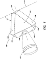
- a Fabry-Perot spacer generally indicated at 100 having a tetrahedral shape insensitive to deformational forces such as motional acceleration, harmonic motion, temperature, and/or forces caused by mounting hardware.
- the spacer 100 defines a plurality of triangular faces each indicated at 102, a plurality of corners each indicated at 104, and a plurality of edges each indicated at 106.
- Triangular faces 102 obscured by the spacer 100 in FIG. 1 are shown in the cross-sectional view of FIG. 3 .
- the Fabry-Perot spacer 100 is comprised of four triangular faces 102, four corners 104, and six edges 106.
- the plurality of triangular faces 102 can be shaped to form flat surfaces.
- the mechanical resonance frequency of the Fabry-Perot spacer 100 is increased, making the spacer 100 largely force insensitive.
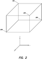
- a nominally 2" cube is reduced by approximately .75" at each of the plurality of triangular faces 102.
- the same scale applies for a 1" cube.
- the spacer 100 is composed of any material known in the art substantially resistant to elastic deformation.
- the spacer 100 may be composed of ultra low expansion glass, Corning® ULE offered by Corning, Inc.
- the corners 104 of the spacer 100 are truncated to form a plurality of mounting surfaces 104.
- the corners 104 are truncated in a planar manner to form flat surfaces ideal for restraining the Fabry-Perot spacer 100 (e.g., the mounting plane of a truncated corner (i.e., mounting surface 104) is shown as dotted line 110 in FIG. 1 ).
- the mounting surfaces 104 can be configured to receive a mounting apparatus (not shown).
- the mounting apparatus can include a four point mount system, in which each point is configured to make contact with a mounting surface 104 and apply a compressive force toward the center of the spacer 100 to restrain the spacer 100.
- a four point mounting system prevents rotation of the spacer 100, while applying minimal contact pressure that could result in unwanted elastic deformation.
- Other embodiments of the mounting apparatus may include any number of mounting interfaces, such as a two or three point mounting system.
- the mounting apparatus can include any restraining system known in the art to effectively hold a Fabry-Perot spacer.
- each point of the four point mounting system can include a holding sphere configured to make contact with a mounting surface 104 of the Fabry-Perot spacer 100 and direct a compressive force towards the center of the spacer 100.
- the restraining system of the mounting apparatus can include posts or brackets.
- the edges 106 of the Fabry-Perot spacer 100 are truncated.
- the six edges 106 of the Fabry-Perot spacer 100 may each be truncated at a pre-determined angle to form six planar surfaces.
- each edge 106 is truncated at a pre-determined angle (shown as ⁇ ) from the plane 110 of a corresponding mounting surface 104.
- ⁇ a pre-determined angle
- the tetrahedral shape of the spacer 100 offers improved insensitivity as a result of at least reduced mass and reduced symmetry. Truncated corners 104 and/or edges 106 further reduce the mass and the symmetry of the spacer 100, additionally increasing insensitivity of the resonator to disruptive forces.
- the optimal mounting angle ( ⁇ ) at which each edge 106 of the Fabry-Perot spacer 100 is truncated (for a four point mounting system) to achieve desirable insensitivity to external forces is determined by combining the desirable qualities of a spherical Fabry-Perot spacer, with the desirable qualities of a cubic Fabry-Perot spacer.
- equation (1) shows the optimal mounting angle for a two point mount (e.g., utilized with a spherical spacer). In a typical two point mount, force is applied to the spherical spacer from opposite directions.
- the mounting angle, cps refers to the angle between the body of the spherical spacer and the mounting surface.
- ⁇ s tan ⁇ 1 1 1 ⁇ ⁇
- mounting equations (6) and (7) can be derived for a four point mounting system, where ⁇ 1 is the mounting angle at mount point one 202, ⁇ 2 is the mount angle at mount point two 204, ⁇ 3 is the mount angle at mount point three 206, and ⁇ 4 is the mount angle at mount point four 208.
- ⁇ 1 tan -1 (1 - ⁇ )
- ⁇ 3 ⁇ 1
- the spacer 100 can further include a first mirror channel 112 configured to receive a first optical element 108 (shown in FIG. 1 ) and a second mirror channel 114 configured to receive a second optical element (obscured by the spacer 100 in FIG. 1 ).
- the first and the second optical elements can include a curved mirror 122 (shown in an expanded view of first optical element 108).
- the curved mirror 122 can be spherically or aspherically curved.
- An input light wave entering the first mirror 108 is reflected between the first mirror 108 and second mirror multiple times. Each time the input light wave reflects off of the second mirror, a portion is reflected back towards the first mirror 108 and another portion passes through the second mirror as an output wave.
- By adjusting the space between the first mirror and the second mirror it is possible to control the wavelengths of the output waves transmitted by the Fabry-Perot resonator.
- first and the second mirror are configured to produce multiple transmitted rays delayed at even intervals.
- the first mirror channel 112 and the second mirror channel 114 provide support, respectively, for the first and the second optical elements.
- the first and second mirror channels (112 and 114) are bonded, respectively, to the first and second mirrors to prevent dislodging as a result of vibration or external forces.
- the first and second mirror channels (112 and 114) may be located on distal truncated edges, such as truncated edges 106, of the Fabry-Perot spacer 100.
- the first and the second mirror can further include a first and a second thermal stability ring, respectively.
- a thermal stability ring can include any known shielding device configured to protect the externally facing surface of the first or second mirror from external thermal forces, such as temperature variations.
- the stability rings of one embodiment can be formed from the same material as the Fabry-Perot spacer 100, such as ultra low expansion glass, Corning® ULE offered by Corning, Inc.
- the Fabry-Perot spacer 100 further includes an optical cavity 116 extended linearly through the center of the tetrahedral body between the first mirror channel 112 and the second mirror channel 114.
- the optical cavity 116 (otherwise referred to herein as "gap") provides an opening in the spacer 100 that allows the propagation of the ray of light between the two optical elements.
- the optical cavity 116 has a length of one inch.
- different applications of a Fabry-Perot resonator may require different cavity lengths, such as one and a half or two inches. Therefore, the length of the optical cavity 116 in the Fabry-Perot spacer 100 can be modified according to the application.
- the cavity 116 can have a substantially cylindrical shape.
- various other embodiments of the Fabry-Perot spacer can include a first bore 118 and a second bore 120 extending orthogonally through the center of the tetrahedral body relative to each other and the optical cavity 116. Similar to the optical cavity 116, in various embodiments, the first bore 118 and the second bore 120 can be cylindrical in shape. In a further embodiment, the first and the second bore (118 and 120) can be configured to receive a vacuum system for creating a vacuum within the Fabry-Perot spacer 100. In other embodiments, the first and second bore (118 and 120) can be configured to receive a gas or liquid.
- the first and the second bore (118 and 120) can each have a pair of mirror channels for receiving a second and a third pair of optical elements.
- optical elements can include curved mirrors, and in particular, spherically curved mirrors.
- the Fabry-Perot spacer 100 has three channels extending orthogonal to each other through the center of the spacer (i.e., optical cavity 116, first bore 118, and second bore 120).
- the spacer 100 includes one optical element (e.g., curved mirror 122) at the end of each channel, for a total of six optical elements.
- the first and second bore can be routed off-axis of the center of the Fabry-Perot spacer 100.
- Table 1 Eigenfrequencies of a 1" and a 2" Tetrahedral and Cubic Spacer Cubic 2" Cubic 1" f f' Q f f' Q 18670 9.33 1000.536 38019 19 1000.5 18727 9.36 1000.374 38153 19 1004.026 19740 9.87 1000 40300 20.1 1002.488 22364 11.18 1000.179 45427 22.7 1000.595 23142 11.57 1000.086 47138 23.6 998.6864 23187 11.59 1000.112 47215 23.6 1000.318 Tetrahedral 2" Tetrahedral 1" f f' Q f f' Q 20843 10.42 1000.144 55839 28 997.125 20913 10.45 1000.622 41969 21 999.2619 22088 11.04 1000.362 42103 21 1002.452 27235 13.61 1000.551 44429 22 10
- Table 1 shows a comparison of the first six mechanical resonance eigenmodes and the corresponding Q-factors (reflectivity of the optical elements) for the tetrahedral shape, compared with a cubic shaped spacer.
- eigenmodes represent the normal mode of vibration of an oscillating system.
- eigenfrequencies are the natural frequencies of vibration.
- Table 1 shows a comparison of both spacers with a cavity length of one inch and two inches. "f' represents the resonant frequency, "f” represents the imaginary component of the resonant frequency, and "Q" represents the quality factor. While the quality factors remain substantially constant between the tetrahedral and cubic shapes, there is a substantial improvement of the resonant frequency.
- the 2" tetrahedral shaped spacer demonstrates a first resonant frequency of 20843 Hz, while the 2" cubic shaped spacer demonstrates a first resonant frequency of 18670 Hz.
- higher resonance frequencies increase the Fabry-Perot spacer's insensitivity to disruptive forces.
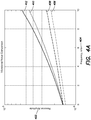
- FIGS. 4A and 4B show a visual representation of Table 1, the frequency response of a Fabry-Perot spacer having a tetrahedral shape is compared with a Fabry-Perot spacer having a cubic shape, in range of 0 to 10 kHz.
- FIG. 4A shows a 1" tetrahedral shape trace 406, a 1" cubic shape trace 408, a 2" tetrahedral shape trace 410, and a 2" cubic shape trace 412.
- FIG. 4A has a first axis 402 defining a response amplitude, and a second axis 404 defining a frequency in kHz.
- FIG. 4B shows an expanded view of FIG.
- the tetrahedral spacer shows improvements in both a one inch cavity length and a two inch cavity length.
- the response amplitude of both the one inch and two inch cavity tetrahedral spacers are lower than the cubic spacers at frequencies below 2 kHz.
- the 1" tetrahedral shaped spacer demonstrates a fractional length change response amplitude of 1.6 part per million
- the 1" cubic shaped spacer demonstrates a response amplitude of 1.4 part per million.
- vibrational noise as a result of acceleration for example on an aircraft, spacecraft, or boat, will be less than 2 kHz.
- aspects and embodiments are directed to Fabry-Perot resonators.
- embodiments include resonator systems and spacers insensitive to deforming forces.
- One embodiment includes a resilient tetrahedral shaped Fabry-Perot spacer having characteristics of a spherical and cubic spacer, and is compatible with ring compensators. Reduced mass as well reduced symmetry of the spacer, due to the tetrahedral shape of the spacer, increases insensitivity to acceleration, vibration, and thermal forces across the frequency spectrum critical to airborne applications.
- truncated corners and/or edges of the spacer further reduce the mass and the symmetry of the spacer, additionally increasing insensitivity of the resonator to disruptive forces.
- the use of thermal stability rings protects externally facing surfaces of optical elements in the Fabry-Perot resonator, increasing insensitivity to thermal forces.
- the one or more embodiments as described herein may be executed conjunctively or adjunctively with additional embodiments.
- the Fabry-Perot resonator system 100 may include a first optical element susceptible to temperature variations. Indeed, various embodiments may be combined as necessary to conform to the demands of airborne applications.
Landscapes
- Physics & Mathematics (AREA)
- Spectroscopy & Molecular Physics (AREA)
- General Physics & Mathematics (AREA)
- Optics & Photonics (AREA)
- Nonlinear Science (AREA)
- Mechanical Light Control Or Optical Switches (AREA)
- Optical Filters (AREA)
- Lasers (AREA)
- Optical Modulation, Optical Deflection, Nonlinear Optics, Optical Demodulation, Optical Logic Elements (AREA)
Applications Claiming Priority (3)
| Application Number | Priority Date | Filing Date | Title |
|---|---|---|---|
| US14/575,356 US10066994B2 (en) | 2014-12-18 | 2014-12-18 | Pyramidal spacer for increased stability Fabry Perot resonator |
| EP15787117.9A EP3234663B1 (de) | 2014-12-18 | 2015-10-15 | Pyramidenförmiger abstandshalter für fabry-perot-resonator mit erhöhter stabilität |
| PCT/US2015/055695 WO2016099637A1 (en) | 2014-12-18 | 2015-10-15 | Pyramidal spacer for increased stability fabry perot resonator |
Related Parent Applications (1)
| Application Number | Title | Priority Date | Filing Date |
|---|---|---|---|
| EP15787117.9A Division EP3234663B1 (de) | 2014-12-18 | 2015-10-15 | Pyramidenförmiger abstandshalter für fabry-perot-resonator mit erhöhter stabilität |
Publications (1)
| Publication Number | Publication Date |
|---|---|
| EP3779532A1 true EP3779532A1 (de) | 2021-02-17 |
Family
ID=54360584
Family Applications (2)
| Application Number | Title | Priority Date | Filing Date |
|---|---|---|---|
| EP20196915.1A Withdrawn EP3779532A1 (de) | 2014-12-18 | 2015-10-15 | Pyramidenförmiger abstandshalter für fabry-perot-resonator mit erhöhter stabilität |
| EP15787117.9A Active EP3234663B1 (de) | 2014-12-18 | 2015-10-15 | Pyramidenförmiger abstandshalter für fabry-perot-resonator mit erhöhter stabilität |
Family Applications After (1)
| Application Number | Title | Priority Date | Filing Date |
|---|---|---|---|
| EP15787117.9A Active EP3234663B1 (de) | 2014-12-18 | 2015-10-15 | Pyramidenförmiger abstandshalter für fabry-perot-resonator mit erhöhter stabilität |
Country Status (6)
| Country | Link |
|---|---|
| US (1) | US10066994B2 (de) |
| EP (2) | EP3779532A1 (de) |
| JP (1) | JP6482670B2 (de) |
| CN (1) | CN107003492B (de) |
| IL (1) | IL252207B (de) |
| WO (1) | WO2016099637A1 (de) |
Families Citing this family (2)
| Publication number | Priority date | Publication date | Assignee | Title |
|---|---|---|---|---|
| USD849508S1 (en) * | 2017-12-15 | 2019-05-28 | Udi Shorr | Hemispheric peg support |
| USD849509S1 (en) * | 2017-12-25 | 2019-05-28 | Udi Shorr | Spherical peg support |
Citations (1)
| Publication number | Priority date | Publication date | Assignee | Title |
|---|---|---|---|---|
| WO2012063033A2 (en) * | 2010-11-12 | 2012-05-18 | The Secretary Of State For Business Innovation & Skills Of Her Majesty's Britannic Government | Force-insensitive fabry-perot etalon |
Family Cites Families (4)
| Publication number | Priority date | Publication date | Assignee | Title |
|---|---|---|---|---|
| US4466699A (en) * | 1982-01-22 | 1984-08-21 | Honeywell Inc. | Curved tunable Fabry-Perot filter |
| US6902280B2 (en) * | 2002-12-17 | 2005-06-07 | Avery Dennison Corporation | Tri-level cube corner ruling |
| FR2935845B1 (fr) * | 2008-09-05 | 2010-09-10 | Centre Nat Rech Scient | Cavite optique amplificatrice de type fabry-perot |
| US9515448B2 (en) * | 2012-09-26 | 2016-12-06 | Raytheon Company | Microchip laser with single solid etalon and interfacial coating |
-
2014
- 2014-12-18 US US14/575,356 patent/US10066994B2/en active Active
-
2015
- 2015-10-15 EP EP20196915.1A patent/EP3779532A1/de not_active Withdrawn
- 2015-10-15 EP EP15787117.9A patent/EP3234663B1/de active Active
- 2015-10-15 JP JP2017532900A patent/JP6482670B2/ja not_active Expired - Fee Related
- 2015-10-15 WO PCT/US2015/055695 patent/WO2016099637A1/en not_active Ceased
- 2015-10-15 CN CN201580066115.3A patent/CN107003492B/zh not_active Expired - Fee Related
-
2017
- 2017-05-10 IL IL25220717A patent/IL252207B/en active IP Right Grant
Patent Citations (1)
| Publication number | Priority date | Publication date | Assignee | Title |
|---|---|---|---|---|
| WO2012063033A2 (en) * | 2010-11-12 | 2012-05-18 | The Secretary Of State For Business Innovation & Skills Of Her Majesty's Britannic Government | Force-insensitive fabry-perot etalon |
Non-Patent Citations (2)
| Title |
|---|
| A DIDIER ET AL: "Ultra compact reference ULE cavity", 2014 EUROPEAN FREQUENCY AND TIME FORUM (EFTF), 26 June 2014 (2014-06-26), pages 514 - 517, XP055236099, DOI: 10.1109/EFTF.2014.7331550 * |
| DAVID R LEIBRANDT ET AL: "Spherical reference cavities for frequency stabilization of lasers in non-laboratory environments References and links 4 / OPTICS EXPRESS 3471", OPTICAL SOCIETY OF AMERICA OCIS CODES PHYS. REV. LETT. PHYS. REV. LETT. CLASS. QUANTUM GRAV. SCIENCE PHYS. REV. LETT. PHYS. TODAY OPT. LETT. APPL. PHYS. B OPT. LETT. PHYS. REV. A PHYS. REV. A PHYS. REV. A PHYS. REV. A J. OPT. SOC. AM. B APP. PHYS. B, 14 February 2011 (2011-02-14), pages 3799 - 3802, XP055236249, Retrieved from the Internet <URL:https://www.osapublishing.org/DirectPDFAccess/4972D8A2-C21D-39A5-E86B4828B76233D5_209977/oe-19-4-3471.pdf?da=1&id=209977&seq=0&mobile=no> [retrieved on 20151214] * |
Also Published As
| Publication number | Publication date |
|---|---|
| JP2018503863A (ja) | 2018-02-08 |
| EP3234663A1 (de) | 2017-10-25 |
| IL252207A0 (en) | 2017-07-31 |
| WO2016099637A1 (en) | 2016-06-23 |
| CN107003492B (zh) | 2019-08-27 |
| IL252207B (en) | 2019-11-28 |
| CN107003492A (zh) | 2017-08-01 |
| US10066994B2 (en) | 2018-09-04 |
| EP3234663B1 (de) | 2020-09-23 |
| JP6482670B2 (ja) | 2019-03-13 |
| US20160178436A1 (en) | 2016-06-23 |
Similar Documents
| Publication | Publication Date | Title |
|---|---|---|
| US5550669A (en) | Flexure design for a fast steering scanning mirror | |
| EP2829925B1 (de) | Atomarsensorphysikpackung mit optisch transparenten Scheiben und externen Keilen | |
| US2988959A (en) | Sandwich mirror | |
| EP3234663B1 (de) | Pyramidenförmiger abstandshalter für fabry-perot-resonator mit erhöhter stabilität | |
| EP2638418B1 (de) | Kraftunempfindliches fabry-perot-interferometer | |
| JP2001194157A (ja) | 角速度センサ | |
| US3832040A (en) | Fixing device for a component of a system | |
| US4723256A (en) | Optical resonator for laser oscillating apparatus | |
| US3582190A (en) | High power mirror | |
| US3404352A (en) | Mirror-supporting structure for lasers | |
| AU2022256205A1 (en) | Isolated ring cavity resonator | |
| Ames et al. | Using iridium films to compensate for piezo-electric materials processing stresses in adjustable x-ray optics | |
| US12038583B2 (en) | Head-mounted display | |
| EP4070035B1 (de) | Kammer zur vibrations- und umweltisolation von dünnen wafern | |
| GB2251120A (en) | Passive pathlength control mirror for laser | |
| US3224331A (en) | Sinusoidal shaped lens for light wave communication | |
| JPH10163549A (ja) | レーザ光源装置、および、レーザ光源の支持構造 | |
| Xing et al. | Development of space-borne transportable high-finesse Fabry–Pérot cavity and its performance in ultra-stable laser | |
| CN108254851B (zh) | 伸缩式气动自适应电磁转换器 | |
| US2423061A (en) | Piezoelectric device and method of manufacture | |
| US8958452B2 (en) | System, apparatus and method employing a dual head laser | |
| JPH07111352A (ja) | レーザー発振器 | |
| Smithson | Active optics for astronomy-Segmented mirror-atmospheric seeing correction | |
| JP5275054B2 (ja) | Atカット水晶振動子 | |
| Goodman et al. | SLMS athermal technology for high-quality wavefront control |
Legal Events
| Date | Code | Title | Description |
|---|---|---|---|
| PUAI | Public reference made under article 153(3) epc to a published international application that has entered the european phase |
Free format text: ORIGINAL CODE: 0009012 |
|
| STAA | Information on the status of an ep patent application or granted ep patent |
Free format text: STATUS: THE APPLICATION HAS BEEN PUBLISHED |
|
| AC | Divisional application: reference to earlier application |
Ref document number: 3234663 Country of ref document: EP Kind code of ref document: P |
|
| AK | Designated contracting states |
Kind code of ref document: A1 Designated state(s): AL AT BE BG CH CY CZ DE DK EE ES FI FR GB GR HR HU IE IS IT LI LT LU LV MC MK MT NL NO PL PT RO RS SE SI SK SM TR |
|
| STAA | Information on the status of an ep patent application or granted ep patent |
Free format text: STATUS: REQUEST FOR EXAMINATION WAS MADE |
|
| 17P | Request for examination filed |
Effective date: 20210806 |
|
| RBV | Designated contracting states (corrected) |
Designated state(s): AL AT BE BG CH CY CZ DE DK EE ES FI FR GB GR HR HU IE IS IT LI LT LU LV MC MK MT NL NO PL PT RO RS SE SI SK SM TR |
|
| GRAP | Despatch of communication of intention to grant a patent |
Free format text: ORIGINAL CODE: EPIDOSNIGR1 |
|
| STAA | Information on the status of an ep patent application or granted ep patent |
Free format text: STATUS: GRANT OF PATENT IS INTENDED |
|
| RIC1 | Information provided on ipc code assigned before grant |
Ipc: G02F 1/21 19740701ALI20230110BHEP Ipc: G01J 3/26 19680901ALI20230110BHEP Ipc: G01J 3/02 19680901ALI20230110BHEP Ipc: G02B 7/182 19900101ALI20230110BHEP Ipc: G02B 5/28 19680901AFI20230110BHEP |
|
| INTG | Intention to grant announced |
Effective date: 20230203 |
|
| STAA | Information on the status of an ep patent application or granted ep patent |
Free format text: STATUS: THE APPLICATION IS DEEMED TO BE WITHDRAWN |
|
| 18D | Application deemed to be withdrawn |
Effective date: 20230614 |