EP3779475B1 - Circuit de detection d'isolement et methode de detection d'isolement - Google Patents
Circuit de detection d'isolement et methode de detection d'isolement Download PDFInfo
- Publication number
- EP3779475B1 EP3779475B1 EP20740929.3A EP20740929A EP3779475B1 EP 3779475 B1 EP3779475 B1 EP 3779475B1 EP 20740929 A EP20740929 A EP 20740929A EP 3779475 B1 EP3779475 B1 EP 3779475B1
- Authority
- EP
- European Patent Office
- Prior art keywords
- module
- sampling
- voltage
- circuit
- resistor
- Prior art date
- Legal status (The legal status is an assumption and is not a legal conclusion. Google has not performed a legal analysis and makes no representation as to the accuracy of the status listed.)
- Active
Links
- 238000009413 insulation Methods 0.000 title claims description 90
- 238000001514 detection method Methods 0.000 title claims description 62
- 238000005070 sampling Methods 0.000 claims description 111
- 238000002955 isolation Methods 0.000 claims description 60
- 239000003990 capacitor Substances 0.000 claims description 33
- 238000001914 filtration Methods 0.000 claims description 17
- 238000000034 method Methods 0.000 claims description 17
- 238000012545 processing Methods 0.000 claims description 14
- 230000010363 phase shift Effects 0.000 claims description 13
- 238000010586 diagram Methods 0.000 description 7
- 239000013256 coordination polymer Substances 0.000 description 4
- 238000002347 injection Methods 0.000 description 4
- 239000007924 injection Substances 0.000 description 4
- 230000001052 transient effect Effects 0.000 description 4
- 101100290388 Neurospora crassa (strain ATCC 24698 / 74-OR23-1A / CBS 708.71 / DSM 1257 / FGSC 987) rnp-2 gene Proteins 0.000 description 3
- 238000012360 testing method Methods 0.000 description 3
- PXHVJJICTQNCMI-UHFFFAOYSA-N Nickel Chemical compound [Ni] PXHVJJICTQNCMI-UHFFFAOYSA-N 0.000 description 2
- 230000015572 biosynthetic process Effects 0.000 description 2
- 101150033698 cnp-2 gene Proteins 0.000 description 2
- 230000007274 generation of a signal involved in cell-cell signaling Effects 0.000 description 2
- 229910052744 lithium Inorganic materials 0.000 description 2
- 238000005259 measurement Methods 0.000 description 2
- 230000000630 rising effect Effects 0.000 description 2
- 238000010187 selection method Methods 0.000 description 2
- 238000003786 synthesis reaction Methods 0.000 description 2
- UFHFLCQGNIYNRP-UHFFFAOYSA-N Hydrogen Chemical compound [H][H] UFHFLCQGNIYNRP-UHFFFAOYSA-N 0.000 description 1
- WHXSMMKQMYFTQS-UHFFFAOYSA-N Lithium Chemical compound [Li] WHXSMMKQMYFTQS-UHFFFAOYSA-N 0.000 description 1
- HBBGRARXTFLTSG-UHFFFAOYSA-N Lithium ion Chemical compound [Li+] HBBGRARXTFLTSG-UHFFFAOYSA-N 0.000 description 1
- FKNQFGJONOIPTF-UHFFFAOYSA-N Sodium cation Chemical compound [Na+] FKNQFGJONOIPTF-UHFFFAOYSA-N 0.000 description 1
- JDZCKJOXGCMJGS-UHFFFAOYSA-N [Li].[S] Chemical compound [Li].[S] JDZCKJOXGCMJGS-UHFFFAOYSA-N 0.000 description 1
- 239000002253 acid Substances 0.000 description 1
- 238000013461 design Methods 0.000 description 1
- 238000011161 development Methods 0.000 description 1
- 230000000694 effects Effects 0.000 description 1
- 230000005611 electricity Effects 0.000 description 1
- 230000005284 excitation Effects 0.000 description 1
- 230000005669 field effect Effects 0.000 description 1
- 229910052739 hydrogen Inorganic materials 0.000 description 1
- 239000001257 hydrogen Substances 0.000 description 1
- 229910001416 lithium ion Inorganic materials 0.000 description 1
- 229910044991 metal oxide Inorganic materials 0.000 description 1
- 150000004706 metal oxides Chemical class 0.000 description 1
- 239000000203 mixture Substances 0.000 description 1
- 238000012806 monitoring device Methods 0.000 description 1
- 229910052759 nickel Inorganic materials 0.000 description 1
- 230000003287 optical effect Effects 0.000 description 1
- 239000004065 semiconductor Substances 0.000 description 1
- 229910001415 sodium ion Inorganic materials 0.000 description 1
- 239000000243 solution Substances 0.000 description 1
Images

Classifications
-
- G—PHYSICS
- G01—MEASURING; TESTING
- G01R—MEASURING ELECTRIC VARIABLES; MEASURING MAGNETIC VARIABLES
- G01R31/00—Arrangements for testing electric properties; Arrangements for locating electric faults; Arrangements for electrical testing characterised by what is being tested not provided for elsewhere
- G01R31/36—Arrangements for testing, measuring or monitoring the electrical condition of accumulators or electric batteries, e.g. capacity or state of charge [SoC]
- G01R31/389—Measuring internal impedance, internal conductance or related variables
-
- G—PHYSICS
- G01—MEASURING; TESTING
- G01R—MEASURING ELECTRIC VARIABLES; MEASURING MAGNETIC VARIABLES
- G01R31/00—Arrangements for testing electric properties; Arrangements for locating electric faults; Arrangements for electrical testing characterised by what is being tested not provided for elsewhere
- G01R31/12—Testing dielectric strength or breakdown voltage ; Testing or monitoring effectiveness or level of insulation, e.g. of a cable or of an apparatus, for example using partial discharge measurements; Electrostatic testing
- G01R31/14—Circuits therefor, e.g. for generating test voltages, sensing circuits
-
- G—PHYSICS
- G01—MEASURING; TESTING
- G01R—MEASURING ELECTRIC VARIABLES; MEASURING MAGNETIC VARIABLES
- G01R31/00—Arrangements for testing electric properties; Arrangements for locating electric faults; Arrangements for electrical testing characterised by what is being tested not provided for elsewhere
- G01R31/36—Arrangements for testing, measuring or monitoring the electrical condition of accumulators or electric batteries, e.g. capacity or state of charge [SoC]
- G01R31/364—Battery terminal connectors with integrated measuring arrangements
-
- G—PHYSICS
- G01—MEASURING; TESTING
- G01R—MEASURING ELECTRIC VARIABLES; MEASURING MAGNETIC VARIABLES
- G01R31/00—Arrangements for testing electric properties; Arrangements for locating electric faults; Arrangements for electrical testing characterised by what is being tested not provided for elsewhere
- G01R31/36—Arrangements for testing, measuring or monitoring the electrical condition of accumulators or electric batteries, e.g. capacity or state of charge [SoC]
- G01R31/3644—Constructional arrangements
-
- G—PHYSICS
- G01—MEASURING; TESTING
- G01R—MEASURING ELECTRIC VARIABLES; MEASURING MAGNETIC VARIABLES
- G01R31/00—Arrangements for testing electric properties; Arrangements for locating electric faults; Arrangements for electrical testing characterised by what is being tested not provided for elsewhere
- G01R31/50—Testing of electric apparatus, lines, cables or components for short-circuits, continuity, leakage current or incorrect line connections
- G01R31/52—Testing for short-circuits, leakage current or ground faults
-
- G—PHYSICS
- G01—MEASURING; TESTING
- G01R—MEASURING ELECTRIC VARIABLES; MEASURING MAGNETIC VARIABLES
- G01R27/00—Arrangements for measuring resistance, reactance, impedance, or electric characteristics derived therefrom
- G01R27/02—Measuring real or complex resistance, reactance, impedance, or other two-pole characteristics derived therefrom, e.g. time constant
- G01R27/025—Measuring very high resistances, e.g. isolation resistances, i.e. megohm-meters
-
- G—PHYSICS
- G01—MEASURING; TESTING
- G01R—MEASURING ELECTRIC VARIABLES; MEASURING MAGNETIC VARIABLES
- G01R27/00—Arrangements for measuring resistance, reactance, impedance, or electric characteristics derived therefrom
- G01R27/02—Measuring real or complex resistance, reactance, impedance, or other two-pole characteristics derived therefrom, e.g. time constant
- G01R27/16—Measuring impedance of element or network through which a current is passing from another source, e.g. cable, power line
- G01R27/18—Measuring resistance to earth, i.e. line to ground
Definitions
- the present application relates to the field of new energy, in particular, to an insulation detection circuit, a detection method and a battery management system.
- the use of electric vehicles to replace fossil-fueled vehicles has become a trend in the development of the automotive industry.
- the mileage, service life, and safety of use of battery packs are particularly important for electric vehicles.
- the battery pack is one of key parts of an electric vehicle, the safety of high-voltage electricity of the battery pack must be put into one of the first considerations of a power battery system. Therefore, the detection of insulation performance of the electric vehicle is an essential part of the design.
- the main methods for detecting insulation resistance include high-frequency signal injection method and resistance voltage division method.
- the detection result of the insulation resistance value is likely to be affected by the distributed capacitance of the detection system, and the high-frequency signal causes interference to the direct current system, which results in a large error in the insulation resistance value.
- the resistance voltage division method is adopted, the resistors connected in series reduce the insulation performance, and the high-voltage circuit will cause interference to the low-voltage circuit, which would also reduce the detection precision of the insulation resistance value. Therefore, improving the detection precision of the insulation resistance value is an urgent problem to be solved.
- Document 1 ( CN108445397A ) provides a parameter selection method, apparatus, and computer readable storage medium for an insulation detection circuit.
- the parameter selection method includes: determining an allowable injection frequency range of an AC signal to be injected, according to a predetermined resistance range of an insulation resistance of the power battery under test and a predetermined resistance calculation cycle of the insulation resistance; and selecting an output frequency of the signal generation module according to a lowest frequency to be generated by the signal generation module and the allowable injection frequency range.
- Document 2 ( CN107727934A ) provides an electric vehicle power battery insulation resistance monitoring device based on an amplitude-phase detection principle.
- the device includes a sinusoidal wave generation circuit, a feedback signal sampling circuit, a sinusoidal alternating current signal amplitude detection circuit, a feedback signal amplitude detection circuit and a phase difference measuring circuit.
- the sinusoidal wave generation circuit is configured to generate a sinusoidal alternating current signal serving as a signal source of the system; the feedback signal sampling circuit is configured to sample a feedback signal of the system; the sinusoidal alternating current signal amplitude detection circuit is configured to detect an amplitude of the sinusoidal alternating current signal; the feedback signal amplitude detection circuit is configured to detect an amplitude of the feedback signal; the phase difference measuring circuit is configured to detect a phase difference between the feedback signal and the sinusoidal alternating current signal.
- a control unit obtains measurement signals and calculates the insulation resistance using an insulation resistance calculation formula.
- Document 3 discloses an alternating current excitation insulation detection circuit, which includes an anode insulation resistance Rz and a cathode insulation resistance Rf from a total positive end and a total negative end of a power supply battery set to an electric vehicle body, and further includes an alternating current signal source, a sampling module and a data processing module which are used for detecting the insulation resistance value between the electric vehicle body and the power supply battery set so as to determine the insulation state of the electric vehicle.
- Document 4 discloses a circuit arrangement for detecting short circuits to earth and/or frame for use in a control system which has a non-earthed direct-voltage supply network is specified.
- a test voltage (Uo) is applied via high-resistance sensing resistors (RM1, RM2) to both terminals (U+, U-) of the direct-voltage supply network.
- This test voltage is an alternating squarewave voltage of very low frequency and is balanced with respect to earth potential.
- the response of the network which forms the direct-voltage supply network with its earth-fault resistors (RE1, RE2), is detected by multiple measurement of the voltage (U1, U2) present at the terminals of the direct-voltage supply network with respect to earth potential, and evaluated in an evaluating circuit.
- Embodiments of the present application provide an insulation detection circuit, a detection method and a battery management system, which improve the detection precision of the insulation resistance value.
- an insulation detection circuit where the circuit includes:
- the first voltage dividing module includes a first resistor, where one end of the first resistor is connected to the positive electrode, and the other end of the first resistor is connected to the first isolation module and the second voltage dividing module respectively;
- the sampling module includes a third resistor, which is connected to the first isolation module and the signal generating module respectively.
- the signal generating module is a DDS waveform generator.
- a value of the predetermined frequency ranges from 0.1 Hz to 10 Hz.
- the circuit further includes: a first sampling circuit, where, a first end of the first sampling circuit is connected to the one end of the sampling module, a second end of the first sampling circuit is connected to the processing module, and the first sampling circuit is configured to collect the first sampled signal from the one end of the sampling module.
- the circuit further includes:
- the second insolation module includes: a first voltage follower, where, a first input end of the first voltage follower is connected to the first filtering module, and an output end of the first voltage follower is connected to a second input end of the first voltage follower and the first sampling circuit respectively.
- the circuit further includes: a second sampling circuit, where a first end of the second sampling circuit is connected to the one end of the signal generating module, the second end of the second sampling circuit is connected to the processing module, and the second sampling circuit is configured to collect the second sampled signal from the one end of the signal generating module.
- the circuit further includes:
- the third isolation module includes: a second voltage follower, where, a first input end of the second voltage follower is connected to the second filtering module, and an output end of the second voltage follower is connected to a second input end of the second voltage follower and the second sampling circuit respectively.
- an insulation detection method is provided, where the method is applied to the insulation detection circuit according to the embodiments of the present application and the method includes:
- the signal at the predetermined frequency is injected between the first voltage dividing module and the second voltage dividing module, which reduces the influence of the voltage fluctuation of the power battery on the signal between the sampling module and the first isolation module, thereby improving the accuracy and precision of the detection of the insulation resistance value.
- the power battery to be detected in the embodiments of the present application may be a lithium ion battery, a lithium metal battery, a lead-acid battery, a nickelcadmium battery, a nickel hydrogen battery, a lithium sulfur battery, a lithium air battery, or a sodium ion battery, which will not be limited herein.
- the power battery to be detected may also be a battery cell unit, or a battery module or a battery pack, which will not be limited herein.
- Fig. 1 shows a schematic structural diagram of an insulation detection circuit according to some embodiments of the present application.
- the insulation detection circuit includes:
- Fig. 1 further shows a positive capacitor CP, a negative capacitor CN, a positive insulation resistor RP, and a negative insulation resistor RN of the power battery to be detected.
- the positive capacitor CP and the negative capacitor CN are equivalent capacitors of the power battery to be detected relative to the low-voltage ground.
- the positive insulation resistor RP is an insulation resistor of the positive electrode of the battery to be detected relative to the low-voltage ground
- the negative insulation resistance RN is an insulation resistance of the negative electrode of the power battery relative to the low-voltage ground.
- a first voltage signal between the sampling module H and the first isolation module G1 may be collected from the one end of the sampling module H, and a second voltage signal injected by the signal generating module S may be collected from the one end of the signal generating module S. Since the voltage signal between the sampling module H and the first isolation module G1 will be affected by the insulation resistance value of the power battery to be detected, based on Kirchhoff s law, the insulation resistance value of the power battery to be detected may be calculated according to the first voltage signal and the second voltage signal.
- the signal at the predetermined frequency is injected between the first voltage dividing module F1 and the second voltage dividing F2 module, which reduces the influence of the voltage fluctuation of the power battery to be detected on the signal between the sampling module H and the first isolation module G1, thereby improving the accuracy and precision of the detection of the insulation resistance value.
- the first isolation module G1 in the embodiment of the present application may be an isolation capacitor.
- the signal at the predetermined frequency is injected between the first voltage dividing module F1 and the second voltage dividing module F2 and directly connecting the isolation capacitor to the power battery to be detected is avoided, which solves the problem of the selection of isolation capacitor brought by the voltage withstand level and effectively improves the voltage withstand level of insulation detection.
- the signal generating module S may be a direct digital frequency synthesis (Direct Digital Synthesis, DDS) waveform generator.
- DDS Direct Digital Synthesis
- the frequency stability and accuracy of the signal generated by the DDS waveform generator can reach the same level as the reference frequency, and it can be fine-tuned in frequency over a wide frequency range.
- the signal source designed using this manner can operate in the modulation state, can adjust the output level, and can output various types of waveform, for example, a sine wave, a triangle wave, a square wave, and the like.
- the value of the predetermined frequency of the signal generated by the DDS waveform generator ranges from 0.1 Hz to 10 Hz.
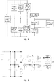
- Fig. 2 shows a schematic structural diagram of an insulation detection circuit according to some other embodiments of the present application.
- Fig. 2 shows the component composition of some of the modules in Fig. 1 .
- the first voltage dividing module F1 may include a resistor RX
- the second voltage dividing module F2 may include a resistor RY and a switch S1
- the first isolation module G1 includes a switch S2 and an isolation capacitor C1.
- One end of the resistor RX is connected to the positive electrode of the power battery to be detected, and the other end of the resistor RX is connected to one end of the resistor RY and one end of the switch S2 respectively.
- the other end of the switch S2 is connected to one end of the isolation capacitor C1.
- the other end of the resistor RY is connected to one end of the switch S1, and the other end of the switch S1 is connected to the negative electrode of the power battery to be detected.
- the switch S1 and the switch S2 may be optical metal oxide semiconductor (MOS) field effect transistors.
- the switch S1 and the switch S2 may also be regular switches.
- the sampling module H includes a sampling resistor R1
- the signal generating module S includes a DDS waveform generator.
- the other end of the isolation capacitor C1 is connected to one end of the sampling resistor R1, and the other end of the sampling resistor R1 is connected to the DDS waveform generator.
- the DDS waveform generator is connected to the power ground.
- the signal generating module S is directly connected to the power ground, and there is no need to isolate the signal generating module S, which reduces the cost.
- the reference ground of the processing module P is also the power ground, i.e., the earth. Therefore, the processing module P can directly process the collected signal, which shortens the detection time and reduces the cost.
- the low-frequency signal is injected between the resistor RX and the resistor RY, which avoids the influence of the voltage fluctuation of the power battery to be detected on the signal between the isolation capacitor C1 and the sampling resistor R1, thereby improving the detection precision of the insulation resistance.
- the resistance value of the resistor RX is equal to the resistance value of the resistor RY.
- the switch S1 and the switch S2 need to be closed. Because the connection position of the high voltage side of the isolation capacitor C1 is at an equivalent electric potential of the voltage at the actual intermediate voltage position of the power battery to be detected, by this manner, the problem of injecting a low frequency alternating current signal into the actual intermediate voltage cell caused by the technology difficulty is solved.
- the branch where the resistor RX is located can be used as a high-voltage sampling circuit for collecting the voltage of the power battery to be detected, which saves the cost.
- the isolation capacitor C1 can isolate the high-voltage sampled signal from the low-voltage sampled signal on the side of the power battery to be detected, which avoids the interference of the high-voltage signal on the low-voltage signal, improving the stability of insulation detection.
- the processing module P can directly collect the first voltage signal from the common end of the sampling resistor R1 and the isolation capacitor C1, and directly collect the second voltage signal from the signal generating module S, or the collection can also be performed through a dedicated sampling circuit.
- the insulation detection circuit further includes a first sampling circuit D1 and a second sampling circuit D2.
- a first end of the first sampling circuit D1 is connected to one end of the sampling resistor R1, and a second end of the first sampling circuit D1 is connected to a processing module P.
- the first sampling circuit D1 is configured to collect a voltage signal between the sampling resistor R1 and the isolation capacitor C1 from the one end of the sampling resistor R1.
- a first end of the second sampling circuit D2 is connected to one end of a signal generating module S, a second end of the second sampling circuit D2 is connected to the processing module P, and the second sampling circuit D2 is configured to collect a voltage signal generated by a DDS signal generator from one end of a signal generating module S.
- the processing module P may be a microcontroller unit (Microcontroller Unit, MCU), which is configured to receive a first sampled signal from the first sampling circuit, receive a second sampled signal from the second sampling circuit, and calculate an insulation resistance value according to the first sampled signal and the second sampled signal.
- MCU Microcontroller Unit
- Fig. 3 shows another schematic structural diagram of an insulation detection circuit according to some other embodiments of the present application.
- Fig. 3 is different from Fig. 1 in that Fig. 3 further includes: a first filtering module B1, a second isolation module G2, a second filtering module B2, a third isolation module G3, a first sampling circuit D1, and a second collecting circuit C2.
- the first filtering module B1 is connected to the one end of the sampling module H and a second insolation module G2 respectively.
- the second isolation module G2 is connected to the first sampling circuit D1.
- the second isolation module G2 is configured to isolate the interference of the first sampling circuit D1 on the signal between the sampling module H and the first isolation module G1.
- the first filtering module B1 includes a resistor R2 and a capacitor C2.
- the second isolation module G2 includes a first voltage follower A1.
- One end of the resistor R2 is connected to the one end of the sampling resistor R1, and the other end of the resistor R2 is connected to one end of the capacitor C2 and a first input end of the first voltage follower A1 respectively.
- the other end of the capacitor C2 is connected to the power ground.
- a second input end of the first voltage follower A1 is connected to an output end of the first voltage follower A1, and the output end of the first voltage follower A1 is connected to the first sampling circuit D1.
- the first filtering module B1 filters the signal between the first isolation module G1 and the sampling module H, which can suppress noise and prevent interference, improving the sampling precision of the signal between the first isolation module G1 and the sampling module H.Thus, the detection precision of the insulation resistance value is improved.
- the first sampling circuit D1 and the second sampling circuit D2 may each include a resistor voltage divider and an MCU.
- the voltage of the sine wave outputted by the DDS waveform generator is relatively high and exceeds the sampling range of the MCU in the first sampling circuit and the MCU in the second sampling circuit, therefore, the voltage signal between the sampling module H and the first isolation module G1 needs to be voltage divided by the resistor voltage divider before the sampling.
- the insulation resistance value is generally large, and direct applying the resistance voltage division will cause current division, which makes the sampling of the voltage signal between the sampling module H and the first isolation module G1 inaccurate, therefore, adding the voltage follower can increase the input impedance and prevent the influence of the first sampling circuit D1 on the sampled signal.
- the voltage follower can also play a role of further filtering.
- the second filtering module B2 is connected to the one end of the signal generating module S and a third isolation module G3 respectively.
- the third isolation module G3 is connected to the second sampling circuit D2, and the third isolation module G3 is configured to isolate the interference of the second sampling circuit D2 on the signal generated by the DDS waveform generator.
- the second filtering module B2 includes a resistor R3 and a capacitor C3.
- the third isolation module G3 includes a second voltage follower A2.
- One end of the resistor R3 is connected to the DDS waveform generator, and the other end of the resistor R3 is connected to one end of the capacitor C3 and a first input end of the second voltage follower A2 respectively.
- the other end of the capacitor C3 is connected to the power ground.
- a second input end of the second voltage follower A2 is connected to an output end of the second voltage follower A2, and the output end of the second voltage follower A2 is connected to the second sampling circuit D2.
- the second filtering module B2 filters the signals generated by the DDS waveform generator, which can suppress noise and prevent interference, improving the sampling precision of the signal generated by the DDS waveform generator, thus, the detection precision of the insulation resistance value is further improved.
- the function of the second voltage follower A2 is similar to that of the first voltage follower A1, which will not be repeated here.
- the embodiments of the present application also provide a battery management system, which includes the insulation detection circuit as described above.
- the insulation resistance value of the power battery to be detected may be calculated according to the first sampled signal between the sampling module H and the first isolation module G1 and the second sampled signal generated by the signal generating module S.
- the calculation process of the insulation resistance value of the power battery to be detected based on the insulation detection circuit discussed above according to the embodiment of the present application is described in detail below.
- Fig. 4 since the internal resistance of the power battery to be detected is very small, the direct current power supply can be considered as equivalently short-circuited, that is, Fig. 2 is considered as equivalent to Fig. 4 .
- the equivalent insulation resistance value Rnp is smaller than RN and RP.
- the insulation resistance value Rnp may be used as a standard for measuring the insulation performance.
- w is an angular frequency of the voltage signal generated by the signal generating module S
- j is a symbol of the imaginary part.
- U is an amplitude value of the voltage signal generated by the DDS signal generator
- u is an amplitude value of the voltage signal between the isolation capacitor C1 and the sampling resistor R1
- U and u are sine wave signals of a same frequency.
- Z Z 1 ⁇ 1 j ⁇ w ⁇ C 1 ⁇ R 4
- phase shift ⁇ may be converted into an expression of a measurable value.
- a first transient voltage of the first sampled signal where the waveform is at the rising edge and a second transient voltage of the second sampled signal where the waveform is at the rising edge at the same time may be respectively obtained as UB and UA.
- Rnp i.e., the insulation resistance value
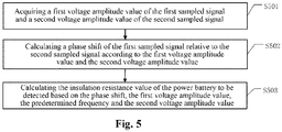
- Fig. 5 is a schematic flowchart of an insulation detection method according to some embodiments of the present application, which is applied to the insulation detection circuit as shown in Fig. 1 to Fig. 3 .
- the insulation detection method according to the embodiment of the present embodiment includes the following steps: S501: acquiring a first voltage amplitude value of the first sampled signal and a second voltage amplitude value of the second sampled signal.
- step S501 if insulation resistance value detection is to be performed, the switch S1 and the switch S2 are closed first to power on the insulation detection circuit.
- the first voltage amplitude value u of the first sampled signal, the second voltage amplitude value U of the second sampled signal and the bias voltage M are acquired, and the first transient voltage UB of the first sampled signal and the second transient voltage UA of the second sampled signal at the same time are acquired.
- the first sampled signal is the signal between the first isolation module G1 and the sampling module H.
- the second sampled signal is the signal generated by the DDS waveform generator.
- S502 calculating a phase shift of the first sampled signal relative to the second sampled signal according to the first voltage amplitude value and the second voltage amplitude value.
- S503 calculating the insulation resistance value of the power battery to be detected based on the phase shift, the first voltage amplitude value, the predetermined frequency and the second voltage amplitude value.
- the insulation resistance value of the power battery to be detected may be calculated according to the phase shift, the first voltage amplitude value, the second voltage amplitude value, the predetermined frequency w, the resistance value of RX, the resistance value of RY, the capacitance value of C1, and the resistance value of R1 in combination with the formula (1) and the formula (8).
Claims (10)
- Circuit de détection d'isolement, comprenant :un premier module de division de tension (F1), une extrémité du premier module de division de tension (F1) étant connectée à une électrode positive d'une batterie de puissance à détecter, et l'autre extrémité du premier module de division de tension (F1) étant respectivement connecté à un premier module d'isolement (G1) et un deuxième module de division de tension (F2) ;le deuxième module de division de tension (F2) étant connecté à une électrode négative de la batterie de puissance à détecter ;le premier module d'isolement (G1) étant connecté à une extrémité d'un module d'échantillonnage (H) ;un module d'échantillonnage (H), l'autre extrémité du module d'échantillonnage (H) étant connectée à une extrémité d'un module de génération de signal (S) ;le module de génération de signal (S), l'autre extrémité du module de génération de signal (S) étant mise à la terre, et le module de génération de signal (S) étant configuré pour envoyer un signal à une fréquence prédéterminée vers la batterie de puissance à détecter ; etun module de traitement (P), configuré pour calculer une valeur de résistance d'isolement de la batterie de puissance à détecter en fonction d'un premier signal échantillonné collecté à l'une extrémité du module d'échantillonnage (H) et d'un deuxième signal échantillonné collecté à l'une extrémité du module de génération de signal (S),dans lequel le circuit de détection d'isolement se caractérise en ce que :le premier module de division de tension (F1) comprend une première résistance (RX), une extrémité de la première résistance (RX) étant connectée à l'électrode positive, et l'autre extrémité de la première résistance (RX) étant connectée respectivement au premier module d'isolement (G1) et au deuxième module de division de tension (F2) ;le deuxième module de division de tension (F2) comprend : une deuxième résistance (RY), une extrémité de la deuxième résistance (RY) étant connectée à l'autre extrémité de la première résistance (RX), et l'autre extrémité de la deuxième résistance (RY) étant connectée à un premier commutateur (S1) ; et le premier commutateur (S1) étant connecté à l'électrode négative ;une valeur de résistance de la première résistance (RX) étant égale à une valeur de résistance de la deuxième résistance (RY) ; etle premier module d'isolement (G1) comprend : un deuxième commutateur (S2), connecté à l'autre extrémité du premier module de division de tension (F1) ; et un condensateur d'isolement (C1), connecté respectivement au deuxième commutateur (S2) et au module d'échantillonnage (H).
- Circuit selon la revendication 1, dans lequel le module d'échantillonnage (H) comprend une troisième résistance (R1), la troisième résistance (R1) étant connectée respectivement au premier module d'isolement (G1) et au module de génération de signal (S).
- Circuit selon la revendication 1, dans lequel une valeur de la fréquence prédéterminée est comprise entre 0,1 Hz et 10 Hz.
- Circuit selon la revendication 1, dans lequel le circuit comprend en outre :
un premier circuit d'échantillonnage (D1), une première extrémité du premier circuit d'échantillonnage (D1) étant connectée à l'une extrémité du module d'échantillonnage (H), une deuxième extrémité du premier circuit d'échantillonnage (D1) étant connectée au module de traitement (P), et le premier circuit d'échantillonnage (D1) étant configuré pour collecter le premier signal échantillonné à l'une extrémité du module d'échantillonnage (H). - Circuit selon la revendication 4, dans lequel le circuit comprend en outre :un premier module de filtrage (B1), connecté respectivement à l'une extrémité du module d'échantillonnage (H) et à un deuxième module d'isolement (G2) ;le deuxième module d'isolement (G2), connecté au premier circuit d'échantillonnage (D1) et configuré pour isoler des interférences du premier circuit d'échantillonnage (D1) sur le premier signal échantillonné.
- Circuit selon la revendication 5, dans lequel le deuxième module d'isolement (G2) comprend :
un premier suiveur de tension (A1), une première extrémité d'entrée du premier suiveur de tension (A1) étant connectée au premier module de filtrage (B1), et une extrémité de sortie du premier suiveur de tension (A1) étant connectée respectivement à une deuxième extrémité d'entrée du premier suiveur de tension (A1) et au premier circuit d'échantillonnage (D1). - Circuit selon la revendication 1, dans lequel le circuit comprend en outre :
un deuxième circuit d'échantillonnage (D2), une première extrémité du deuxième circuit d'échantillonnage (D2) étant connectée à l'une extrémité du module de génération de signal (S), une deuxième extrémité du deuxième circuit d'échantillonnage (D2) étant connectée au module de traitement (P), et le deuxième circuit d'échantillonnage (D2) étant configuré pour collecter le deuxième signal échantillonné à l'une extrémité du module de génération de signal (S). - Circuit selon la revendication 7, dans lequel le circuit comprend en outre :un deuxième module de filtrage (B2), connecté respectivement à l'une extrémité du module de génération de signal (S) et à un troisième module d'isolement (G3) ;le troisième module d'isolement (G3), connecté au deuxième circuit d'échantillonnage (D2) et configuré pour isoler des interférences du deuxième circuit d'échantillonnage (D2) sur le deuxième signal échantillonné.
- Circuit selon la revendication 8, dans lequel le troisième module d'isolement (G3) comprend
un deuxième suiveur de tension (A2), une première extrémité d'entrée du deuxième suiveur de tension (A2) étant connectée au deuxième module de filtrage (B2), et une extrémité de sortie du deuxième suiveur de tension (A2) étant connectée respectivement à une deuxième extrémité d'entrée du deuxième suiveur de tension (A2) et au deuxième circuit d'échantillonnage (D2). - Procédé de détection d'isolement applicable au circuit de détection d'isolement selon l'une quelconque des revendications 1 à 9, dans lequel le procédé comprend :commander le premier commutateur (S1) et le deuxième commutateur (S2) à fermer, afin d'alimenter le circuit de détection d'isolement ;acquérir (S501) une première valeur d'amplitude de tension du premier signal échantillonné et une deuxième valeur d'amplitude de tension du deuxième signal échantillonné ;calculer (S502) un déphasage du premier signal échantillonné par rapport au deuxième signal échantillonné en fonction de la première valeur d'amplitude de tension et de la deuxième valeur d'amplitude de tension ; etcalculer (S503) la valeur de résistance d'isolement de la batterie de puissance à détecter en fonction du déphasage, de la première valeur d'amplitude de tension, de la fréquence prédéterminée et de la deuxième valeur d'amplitude de tension.
Applications Claiming Priority (2)
| Application Number | Priority Date | Filing Date | Title |
|---|---|---|---|
| CN201910037377.7A CN110967607A (zh) | 2019-01-15 | 2019-01-15 | 绝缘检测电路、方法以及电池管理系统 |
| PCT/CN2020/072238 WO2020147746A1 (fr) | 2019-01-15 | 2020-01-15 | Circuit et procédé de test d'isolation et système de gestion de batterie |
Publications (3)
| Publication Number | Publication Date |
|---|---|
| EP3779475A1 EP3779475A1 (fr) | 2021-02-17 |
| EP3779475A4 EP3779475A4 (fr) | 2021-07-14 |
| EP3779475B1 true EP3779475B1 (fr) | 2022-06-08 |
Family
ID=70028510
Family Applications (1)
| Application Number | Title | Priority Date | Filing Date |
|---|---|---|---|
| EP20740929.3A Active EP3779475B1 (fr) | 2019-01-15 | 2020-01-15 | Circuit de detection d'isolement et methode de detection d'isolement |
Country Status (4)
| Country | Link |
|---|---|
| US (1) | US11262413B2 (fr) |
| EP (1) | EP3779475B1 (fr) |
| CN (1) | CN110967607A (fr) |
| WO (1) | WO2020147746A1 (fr) |
Families Citing this family (4)
| Publication number | Priority date | Publication date | Assignee | Title |
|---|---|---|---|---|
| CN112345902A (zh) * | 2020-10-28 | 2021-02-09 | 一巨自动化装备(上海)有限公司 | 一种实现电压均衡的绝缘检测电路 |
| US11833910B2 (en) * | 2021-03-12 | 2023-12-05 | Analog Devices International Unlimited Company | Dynamic isolation monitoring with low sensitivity to noise |
| CN113791277A (zh) | 2021-09-16 | 2021-12-14 | 惠州市乐亿通科技有限公司 | 绝缘电阻检测装置及叉车 |
| CN115144773B (zh) * | 2022-09-01 | 2022-11-08 | 奉加微电子(昆山)有限公司 | 电池组的电压测量系统和方法 |
Citations (1)
| Publication number | Priority date | Publication date | Assignee | Title |
|---|---|---|---|---|
| DE3346387A1 (de) * | 1983-12-22 | 1985-07-04 | Standard Elektrik Lorenz Ag, 7000 Stuttgart | Schaltungsanordnung zur erd- und koerperschlussueberwachung |
Family Cites Families (23)
| Publication number | Priority date | Publication date | Assignee | Title |
|---|---|---|---|---|
| JP3224977B2 (ja) * | 1994-12-12 | 2001-11-05 | 本田技研工業株式会社 | 非接地電源の絶縁検出方法及び装置 |
| TW403838B (en) * | 1997-10-30 | 2000-09-01 | Matsushita Electric Ind Co Ltd | Electric leak detecting method and apparatus for electric motorcars |
| JP2007187454A (ja) | 2006-01-11 | 2007-07-26 | Toyota Motor Corp | 絶縁抵抗低下検出器 |
| US8421467B2 (en) * | 2009-11-19 | 2013-04-16 | Valence Technology, Inc. | Battery insulation resistance measurement methods, insulation resistance measurement methods, insulation resistance determination apparatuses, and articles of manufacture |
| CN102539917A (zh) * | 2010-12-13 | 2012-07-04 | 河北深海电器有限公司 | 车用直流高压系统的绝缘电阻的测量装置及方法 |
| CN102749562B (zh) | 2012-07-13 | 2014-05-14 | 安徽安凯汽车股份有限公司 | 一种电动汽车动力电池的绝缘监测仪及监测方法 |
| CN203368107U (zh) * | 2013-08-09 | 2013-12-25 | 向智勇 | 具有过压过流保护的充电器 |
| CN103761995A (zh) * | 2014-01-29 | 2014-04-30 | 清华大学 | 具有自诊断功能的高温气冷堆外装式过球检测方法及系统 |
| CN104076254A (zh) * | 2014-06-11 | 2014-10-01 | 惠州市亿能电子有限公司 | 一种交流激励绝缘检测电路 |
| KR101619477B1 (ko) * | 2014-12-09 | 2016-05-10 | 현대오트론 주식회사 | 발진기를 이용한 절연 저항 측정 장치 및 방법 |
| CN206235668U (zh) * | 2016-05-30 | 2017-06-09 | 福建万润新能源科技有限公司 | 一种电动汽车高压绝缘故障识别装置 |
| JP6787708B2 (ja) * | 2016-07-13 | 2020-11-18 | 株式会社デンソーテン | 漏電検知装置および漏電検知システム |
| CN106324462B (zh) * | 2016-08-17 | 2020-04-28 | 重庆长安新能源汽车科技有限公司 | 一种绝缘检测方法、电路及新能源汽车 |
| KR101991910B1 (ko) * | 2016-11-16 | 2019-06-21 | 주식회사 엘지화학 | 배터리의 절연 저항 산출 장치 및 방법 |
| CN206292308U (zh) * | 2016-12-19 | 2017-06-30 | 深圳市沃特玛电池有限公司 | 一种电池绝缘电阻检测设备 |
| CN108802494B (zh) * | 2017-05-03 | 2020-03-20 | 华为技术有限公司 | 绝缘电阻的检测电路、检测方法和装置 |
| CN107064638B (zh) * | 2017-05-04 | 2019-09-10 | 北京航天发射技术研究所 | 一种基于注入周期自适应策略的绝缘电阻检测装置及方法 |
| CN107727934A (zh) * | 2017-10-31 | 2018-02-23 | 中国科学技术大学 | 一种基于幅相检测原理的电动汽车动力电池绝缘电阻监测装置 |
| CN108037366A (zh) * | 2018-01-24 | 2018-05-15 | 深圳市清友能源技术有限公司 | 一种电动汽车的绝缘电阻检测系统及其检测方法 |
| CN108445397B (zh) * | 2018-02-01 | 2020-08-18 | 宁德时代新能源科技股份有限公司 | 绝缘检测电路的参数选取方法和装置、存储介质 |
| CN108333492B (zh) * | 2018-02-01 | 2021-01-01 | 宁德时代新能源科技股份有限公司 | 绝缘检测电路及方法、电池管理系统 |
| CN108196176B (zh) * | 2018-03-01 | 2020-12-15 | 威马智慧出行科技(上海)有限公司 | 一种电池包的绝缘检测报警装置及其方法 |
| CN108680793B (zh) * | 2018-07-10 | 2023-04-28 | 天津职业技术师范大学 | 一种纯电动汽车绝缘电阻检测电路及其检测方法 |
-
2019
- 2019-01-15 CN CN201910037377.7A patent/CN110967607A/zh active Pending
-
2020
- 2020-01-15 EP EP20740929.3A patent/EP3779475B1/fr active Active
- 2020-01-15 US US17/051,184 patent/US11262413B2/en active Active
- 2020-01-15 WO PCT/CN2020/072238 patent/WO2020147746A1/fr active Application Filing
Patent Citations (1)
| Publication number | Priority date | Publication date | Assignee | Title |
|---|---|---|---|---|
| DE3346387A1 (de) * | 1983-12-22 | 1985-07-04 | Standard Elektrik Lorenz Ag, 7000 Stuttgart | Schaltungsanordnung zur erd- und koerperschlussueberwachung |
Also Published As
| Publication number | Publication date |
|---|---|
| WO2020147746A1 (fr) | 2020-07-23 |
| US20210231742A1 (en) | 2021-07-29 |
| CN110967607A (zh) | 2020-04-07 |
| EP3779475A1 (fr) | 2021-02-17 |
| EP3779475A4 (fr) | 2021-07-14 |
| US11262413B2 (en) | 2022-03-01 |
Similar Documents
| Publication | Publication Date | Title |
|---|---|---|
| EP3779475B1 (fr) | Circuit de detection d'isolement et methode de detection d'isolement | |
| CN105277898B (zh) | 一种电池荷电状态的检测方法 | |
| EP3617725B1 (fr) | Circuit de détection et procédé de détection de résistance d'isolement, et dispositif | |
| EP3521840B1 (fr) | Circuit et procédé de détection d'isolation et système de gestion de batterie | |
| AU2011267897B2 (en) | Electrical isolation detection with enhanced dynamic range | |
| EP3521839A1 (fr) | Appareil et procédé de sélection de paramètres et support d'informations pour circuit de détection d'isolation | |
| CN102768304B (zh) | 储能系统蓄电池组内阻的在线检测方法 | |
| CN103760492A (zh) | 一种变电站铅酸蓄电池在线性能测试方法 | |
| EP4068621A1 (fr) | Système de stockage d'énergie photovoltaïque et procédé de détection d'impédance d'isolation du sol | |
| CN210015156U (zh) | 一种电流检测电路、装置及电气产品 | |
| CN104062506A (zh) | 蓄电池欧姆内阻的测量方法及装置 | |
| CN205157652U (zh) | 直流小电流二次放电蓄电池内阻在线检测装置 | |
| CN203502555U (zh) | 多功能高压断路器电气特性测试装置 | |
| CN104142487A (zh) | 一种罐式电容式电压互感器带电检测装置 | |
| CN107490744A (zh) | 一种电动汽车供电设备接地连续性的检测电路 | |
| CN105548725A (zh) | 超级电容器在线检测装置及基于该装置检测内阻的方法 | |
| CN102749523B (zh) | 一种应用于光伏逆变系统的直流接地电阻检测电路 | |
| CN202710661U (zh) | 一种应用于光伏逆变系统的直流接地电阻检测电路 | |
| CN111208352A (zh) | 一种蓄电池内阻测量方法及系统 | |
| CN207817067U (zh) | 一种基于幅相检测原理的电动汽车动力电池绝缘电阻监测装置 | |
| WO2020177636A1 (fr) | Circuit de détection d'isolation et procédé ainsi que système de gestion de batterie | |
| CN211043621U (zh) | 蓄电池阻抗测量装置 | |
| CN111308366A (zh) | 一种蓄电池组多参数的监控系统及其使用方法 | |
| CN106226704A (zh) | 一种风电机组蓄电池检测仪 | |
| Nirmala et al. | Iot Based Battery Monitoring System For Solar PV Fed DC-DC Converter |
Legal Events
| Date | Code | Title | Description |
|---|---|---|---|
| STAA | Information on the status of an ep patent application or granted ep patent |
Free format text: STATUS: THE INTERNATIONAL PUBLICATION HAS BEEN MADE |
|
| PUAI | Public reference made under article 153(3) epc to a published international application that has entered the european phase |
Free format text: ORIGINAL CODE: 0009012 |
|
| STAA | Information on the status of an ep patent application or granted ep patent |
Free format text: STATUS: REQUEST FOR EXAMINATION WAS MADE |
|
| 17P | Request for examination filed |
Effective date: 20201029 |
|
| AK | Designated contracting states |
Kind code of ref document: A1 Designated state(s): AL AT BE BG CH CY CZ DE DK EE ES FI FR GB GR HR HU IE IS IT LI LT LU LV MC MK MT NL NO PL PT RO RS SE SI SK SM TR |
|
| AX | Request for extension of the european patent |
Extension state: BA ME |
|
| A4 | Supplementary search report drawn up and despatched |
Effective date: 20210614 |
|
| RIC1 | Information provided on ipc code assigned before grant |
Ipc: G01R 27/02 20060101AFI20210608BHEP Ipc: G01R 31/36 20200101ALI20210608BHEP Ipc: G01R 31/14 20060101ALI20210608BHEP Ipc: G01R 31/52 20200101ALI20210608BHEP Ipc: G01R 27/18 20060101ALI20210608BHEP |
|
| GRAP | Despatch of communication of intention to grant a patent |
Free format text: ORIGINAL CODE: EPIDOSNIGR1 |
|
| STAA | Information on the status of an ep patent application or granted ep patent |
Free format text: STATUS: GRANT OF PATENT IS INTENDED |
|
| DAV | Request for validation of the european patent (deleted) | ||
| DAX | Request for extension of the european patent (deleted) | ||
| INTG | Intention to grant announced |
Effective date: 20220322 |
|
| GRAS | Grant fee paid |
Free format text: ORIGINAL CODE: EPIDOSNIGR3 |
|
| GRAA | (expected) grant |
Free format text: ORIGINAL CODE: 0009210 |
|
| STAA | Information on the status of an ep patent application or granted ep patent |
Free format text: STATUS: THE PATENT HAS BEEN GRANTED |
|
| RAP3 | Party data changed (applicant data changed or rights of an application transferred) |
Owner name: CONTEMPORARY AMPEREX TECHNOLOGY CO., LIMITED |
|
| AK | Designated contracting states |
Kind code of ref document: B1 Designated state(s): AL AT BE BG CH CY CZ DE DK EE ES FI FR GB GR HR HU IE IS IT LI LT LU LV MC MK MT NL NO PL PT RO RS SE SI SK SM TR |
|
| REG | Reference to a national code |
Ref country code: AT Ref legal event code: REF Ref document number: 1497282 Country of ref document: AT Kind code of ref document: T Effective date: 20220615 Ref country code: CH Ref legal event code: EP |
|
| REG | Reference to a national code |
Ref country code: DE Ref legal event code: R096 Ref document number: 602020003493 Country of ref document: DE |
|
| REG | Reference to a national code |
Ref country code: IE Ref legal event code: FG4D |
|
| REG | Reference to a national code |
Ref country code: LT Ref legal event code: MG9D |
|
| REG | Reference to a national code |
Ref country code: NL Ref legal event code: MP Effective date: 20220608 |
|
| PG25 | Lapsed in a contracting state [announced via postgrant information from national office to epo] |
Ref country code: SE Free format text: LAPSE BECAUSE OF FAILURE TO SUBMIT A TRANSLATION OF THE DESCRIPTION OR TO PAY THE FEE WITHIN THE PRESCRIBED TIME-LIMIT Effective date: 20220608 Ref country code: NO Free format text: LAPSE BECAUSE OF FAILURE TO SUBMIT A TRANSLATION OF THE DESCRIPTION OR TO PAY THE FEE WITHIN THE PRESCRIBED TIME-LIMIT Effective date: 20220908 Ref country code: LT Free format text: LAPSE BECAUSE OF FAILURE TO SUBMIT A TRANSLATION OF THE DESCRIPTION OR TO PAY THE FEE WITHIN THE PRESCRIBED TIME-LIMIT Effective date: 20220608 Ref country code: HR Free format text: LAPSE BECAUSE OF FAILURE TO SUBMIT A TRANSLATION OF THE DESCRIPTION OR TO PAY THE FEE WITHIN THE PRESCRIBED TIME-LIMIT Effective date: 20220608 Ref country code: GR Free format text: LAPSE BECAUSE OF FAILURE TO SUBMIT A TRANSLATION OF THE DESCRIPTION OR TO PAY THE FEE WITHIN THE PRESCRIBED TIME-LIMIT Effective date: 20220909 Ref country code: FI Free format text: LAPSE BECAUSE OF FAILURE TO SUBMIT A TRANSLATION OF THE DESCRIPTION OR TO PAY THE FEE WITHIN THE PRESCRIBED TIME-LIMIT Effective date: 20220608 Ref country code: BG Free format text: LAPSE BECAUSE OF FAILURE TO SUBMIT A TRANSLATION OF THE DESCRIPTION OR TO PAY THE FEE WITHIN THE PRESCRIBED TIME-LIMIT Effective date: 20220908 |
|
| REG | Reference to a national code |
Ref country code: AT Ref legal event code: MK05 Ref document number: 1497282 Country of ref document: AT Kind code of ref document: T Effective date: 20220608 |
|
| PG25 | Lapsed in a contracting state [announced via postgrant information from national office to epo] |
Ref country code: RS Free format text: LAPSE BECAUSE OF FAILURE TO SUBMIT A TRANSLATION OF THE DESCRIPTION OR TO PAY THE FEE WITHIN THE PRESCRIBED TIME-LIMIT Effective date: 20220608 Ref country code: LV Free format text: LAPSE BECAUSE OF FAILURE TO SUBMIT A TRANSLATION OF THE DESCRIPTION OR TO PAY THE FEE WITHIN THE PRESCRIBED TIME-LIMIT Effective date: 20220608 |
|
| PG25 | Lapsed in a contracting state [announced via postgrant information from national office to epo] |
Ref country code: NL Free format text: LAPSE BECAUSE OF FAILURE TO SUBMIT A TRANSLATION OF THE DESCRIPTION OR TO PAY THE FEE WITHIN THE PRESCRIBED TIME-LIMIT Effective date: 20220608 |
|
| PG25 | Lapsed in a contracting state [announced via postgrant information from national office to epo] |
Ref country code: SM Free format text: LAPSE BECAUSE OF FAILURE TO SUBMIT A TRANSLATION OF THE DESCRIPTION OR TO PAY THE FEE WITHIN THE PRESCRIBED TIME-LIMIT Effective date: 20220608 Ref country code: SK Free format text: LAPSE BECAUSE OF FAILURE TO SUBMIT A TRANSLATION OF THE DESCRIPTION OR TO PAY THE FEE WITHIN THE PRESCRIBED TIME-LIMIT Effective date: 20220608 Ref country code: RO Free format text: LAPSE BECAUSE OF FAILURE TO SUBMIT A TRANSLATION OF THE DESCRIPTION OR TO PAY THE FEE WITHIN THE PRESCRIBED TIME-LIMIT Effective date: 20220608 Ref country code: PT Free format text: LAPSE BECAUSE OF FAILURE TO SUBMIT A TRANSLATION OF THE DESCRIPTION OR TO PAY THE FEE WITHIN THE PRESCRIBED TIME-LIMIT Effective date: 20221010 Ref country code: ES Free format text: LAPSE BECAUSE OF FAILURE TO SUBMIT A TRANSLATION OF THE DESCRIPTION OR TO PAY THE FEE WITHIN THE PRESCRIBED TIME-LIMIT Effective date: 20220608 Ref country code: EE Free format text: LAPSE BECAUSE OF FAILURE TO SUBMIT A TRANSLATION OF THE DESCRIPTION OR TO PAY THE FEE WITHIN THE PRESCRIBED TIME-LIMIT Effective date: 20220608 Ref country code: CZ Free format text: LAPSE BECAUSE OF FAILURE TO SUBMIT A TRANSLATION OF THE DESCRIPTION OR TO PAY THE FEE WITHIN THE PRESCRIBED TIME-LIMIT Effective date: 20220608 Ref country code: AT Free format text: LAPSE BECAUSE OF FAILURE TO SUBMIT A TRANSLATION OF THE DESCRIPTION OR TO PAY THE FEE WITHIN THE PRESCRIBED TIME-LIMIT Effective date: 20220608 |
|
| PG25 | Lapsed in a contracting state [announced via postgrant information from national office to epo] |
Ref country code: PL Free format text: LAPSE BECAUSE OF FAILURE TO SUBMIT A TRANSLATION OF THE DESCRIPTION OR TO PAY THE FEE WITHIN THE PRESCRIBED TIME-LIMIT Effective date: 20220608 Ref country code: IS Free format text: LAPSE BECAUSE OF FAILURE TO SUBMIT A TRANSLATION OF THE DESCRIPTION OR TO PAY THE FEE WITHIN THE PRESCRIBED TIME-LIMIT Effective date: 20221008 |
|
| REG | Reference to a national code |
Ref country code: DE Ref legal event code: R097 Ref document number: 602020003493 Country of ref document: DE |
|
| PG25 | Lapsed in a contracting state [announced via postgrant information from national office to epo] |
Ref country code: AL Free format text: LAPSE BECAUSE OF FAILURE TO SUBMIT A TRANSLATION OF THE DESCRIPTION OR TO PAY THE FEE WITHIN THE PRESCRIBED TIME-LIMIT Effective date: 20220608 |
|
| PLBE | No opposition filed within time limit |
Free format text: ORIGINAL CODE: 0009261 |
|
| STAA | Information on the status of an ep patent application or granted ep patent |
Free format text: STATUS: NO OPPOSITION FILED WITHIN TIME LIMIT |
|
| PG25 | Lapsed in a contracting state [announced via postgrant information from national office to epo] |
Ref country code: DK Free format text: LAPSE BECAUSE OF FAILURE TO SUBMIT A TRANSLATION OF THE DESCRIPTION OR TO PAY THE FEE WITHIN THE PRESCRIBED TIME-LIMIT Effective date: 20220608 |
|
| 26N | No opposition filed |
Effective date: 20230310 |
|
| PG25 | Lapsed in a contracting state [announced via postgrant information from national office to epo] |
Ref country code: SI Free format text: LAPSE BECAUSE OF FAILURE TO SUBMIT A TRANSLATION OF THE DESCRIPTION OR TO PAY THE FEE WITHIN THE PRESCRIBED TIME-LIMIT Effective date: 20220608 |
|
| PGFP | Annual fee paid to national office [announced via postgrant information from national office to epo] |
Ref country code: DE Payment date: 20221123 Year of fee payment: 4 |
|
| P01 | Opt-out of the competence of the unified patent court (upc) registered |
Effective date: 20230516 |
|
| REG | Reference to a national code |
Ref country code: CH Ref legal event code: PL |
|
| PG25 | Lapsed in a contracting state [announced via postgrant information from national office to epo] |
Ref country code: LU Free format text: LAPSE BECAUSE OF NON-PAYMENT OF DUE FEES Effective date: 20230115 |
|
| REG | Reference to a national code |
Ref country code: BE Ref legal event code: MM Effective date: 20230131 |
|
| PG25 | Lapsed in a contracting state [announced via postgrant information from national office to epo] |
Ref country code: LI Free format text: LAPSE BECAUSE OF NON-PAYMENT OF DUE FEES Effective date: 20230131 Ref country code: CH Free format text: LAPSE BECAUSE OF NON-PAYMENT OF DUE FEES Effective date: 20230131 |
|
| PG25 | Lapsed in a contracting state [announced via postgrant information from national office to epo] |
Ref country code: BE Free format text: LAPSE BECAUSE OF NON-PAYMENT OF DUE FEES Effective date: 20230131 |
|
| PGFP | Annual fee paid to national office [announced via postgrant information from national office to epo] |
Ref country code: GB Payment date: 20231123 Year of fee payment: 5 |
|
| PG25 | Lapsed in a contracting state [announced via postgrant information from national office to epo] |
Ref country code: IT Free format text: LAPSE BECAUSE OF FAILURE TO SUBMIT A TRANSLATION OF THE DESCRIPTION OR TO PAY THE FEE WITHIN THE PRESCRIBED TIME-LIMIT Effective date: 20220608 Ref country code: IE Free format text: LAPSE BECAUSE OF NON-PAYMENT OF DUE FEES Effective date: 20230115 |
|
| PGFP | Annual fee paid to national office [announced via postgrant information from national office to epo] |
Ref country code: FR Payment date: 20231122 Year of fee payment: 5 |