EP3779407B1 - Verfahren zur analyse einer komponente - Google Patents
Verfahren zur analyse einer komponente Download PDFInfo
- Publication number
- EP3779407B1 EP3779407B1 EP20187412.0A EP20187412A EP3779407B1 EP 3779407 B1 EP3779407 B1 EP 3779407B1 EP 20187412 A EP20187412 A EP 20187412A EP 3779407 B1 EP3779407 B1 EP 3779407B1
- Authority
- EP
- European Patent Office
- Prior art keywords
- polarisation
- image
- crystal grain
- component
- pixels
- Prior art date
- Legal status (The legal status is an assumption and is not a legal conclusion. Google has not performed a legal analysis and makes no representation as to the accuracy of the status listed.)
- Active
Links
Images


Classifications
-
- G—PHYSICS
- G01—MEASURING; TESTING
- G01N—INVESTIGATING OR ANALYSING MATERIALS BY DETERMINING THEIR CHEMICAL OR PHYSICAL PROPERTIES
- G01N21/00—Investigating or analysing materials by the use of optical means, i.e. using sub-millimetre waves, infrared, visible or ultraviolet light
- G01N21/17—Systems in which incident light is modified in accordance with the properties of the material investigated
- G01N21/21—Polarisation-affecting properties
-
- F—MECHANICAL ENGINEERING; LIGHTING; HEATING; WEAPONS; BLASTING
- F01—MACHINES OR ENGINES IN GENERAL; ENGINE PLANTS IN GENERAL; STEAM ENGINES
- F01D—NON-POSITIVE DISPLACEMENT MACHINES OR ENGINES, e.g. STEAM TURBINES
- F01D21/00—Shutting-down of machines or engines, e.g. in emergency; Regulating, controlling, or safety means not otherwise provided for
- F01D21/003—Arrangements for testing or measuring
-
- G—PHYSICS
- G01—MEASURING; TESTING
- G01J—MEASUREMENT OF INTENSITY, VELOCITY, SPECTRAL CONTENT, POLARISATION, PHASE OR PULSE CHARACTERISTICS OF INFRARED, VISIBLE OR ULTRAVIOLET LIGHT; COLORIMETRY; RADIATION PYROMETRY
- G01J4/00—Measuring polarisation of light
- G01J4/04—Polarimeters using electric detection means
-
- G—PHYSICS
- G01—MEASURING; TESTING
- G01N—INVESTIGATING OR ANALYSING MATERIALS BY DETERMINING THEIR CHEMICAL OR PHYSICAL PROPERTIES
- G01N21/00—Investigating or analysing materials by the use of optical means, i.e. using sub-millimetre waves, infrared, visible or ultraviolet light
- G01N21/84—Systems specially adapted for particular applications
- G01N21/88—Investigating the presence of flaws or contamination
- G01N21/8806—Specially adapted optical and illumination features
-
- G—PHYSICS
- G01—MEASURING; TESTING
- G01N—INVESTIGATING OR ANALYSING MATERIALS BY DETERMINING THEIR CHEMICAL OR PHYSICAL PROPERTIES
- G01N21/00—Investigating or analysing materials by the use of optical means, i.e. using sub-millimetre waves, infrared, visible or ultraviolet light
- G01N21/84—Systems specially adapted for particular applications
- G01N21/88—Investigating the presence of flaws or contamination
- G01N21/95—Investigating the presence of flaws or contamination characterised by the material or shape of the object to be examined
- G01N21/9515—Objects of complex shape, e.g. examined with use of a surface follower device
-
- G—PHYSICS
- G01—MEASURING; TESTING
- G01N—INVESTIGATING OR ANALYSING MATERIALS BY DETERMINING THEIR CHEMICAL OR PHYSICAL PROPERTIES
- G01N33/00—Investigating or analysing materials by specific methods not covered by groups G01N1/00 - G01N31/00
- G01N33/20—Metals
- G01N33/204—Structure thereof, e.g. crystal structure
- G01N33/2045—Defects
-
- G—PHYSICS
- G06—COMPUTING OR CALCULATING; COUNTING
- G06T—IMAGE DATA PROCESSING OR GENERATION, IN GENERAL
- G06T7/00—Image analysis
- G06T7/0002—Inspection of images, e.g. flaw detection
- G06T7/0004—Industrial image inspection
-
- F—MECHANICAL ENGINEERING; LIGHTING; HEATING; WEAPONS; BLASTING
- F05—INDEXING SCHEMES RELATING TO ENGINES OR PUMPS IN VARIOUS SUBCLASSES OF CLASSES F01-F04
- F05D—INDEXING SCHEME FOR ASPECTS RELATING TO NON-POSITIVE-DISPLACEMENT MACHINES OR ENGINES, GAS-TURBINES OR JET-PROPULSION PLANTS
- F05D2260/00—Function
- F05D2260/80—Diagnostics
-
- F—MECHANICAL ENGINEERING; LIGHTING; HEATING; WEAPONS; BLASTING
- F05—INDEXING SCHEMES RELATING TO ENGINES OR PUMPS IN VARIOUS SUBCLASSES OF CLASSES F01-F04
- F05D—INDEXING SCHEME FOR ASPECTS RELATING TO NON-POSITIVE-DISPLACEMENT MACHINES OR ENGINES, GAS-TURBINES OR JET-PROPULSION PLANTS
- F05D2300/00—Materials; Properties thereof
- F05D2300/10—Metals, alloys or intermetallic compounds
- F05D2300/17—Alloys
-
- F—MECHANICAL ENGINEERING; LIGHTING; HEATING; WEAPONS; BLASTING
- F05—INDEXING SCHEMES RELATING TO ENGINES OR PUMPS IN VARIOUS SUBCLASSES OF CLASSES F01-F04
- F05D—INDEXING SCHEME FOR ASPECTS RELATING TO NON-POSITIVE-DISPLACEMENT MACHINES OR ENGINES, GAS-TURBINES OR JET-PROPULSION PLANTS
- F05D2300/00—Materials; Properties thereof
- F05D2300/60—Properties or characteristics given to material by treatment or manufacturing
- F05D2300/606—Directionally-solidified crystalline structures
-
- F—MECHANICAL ENGINEERING; LIGHTING; HEATING; WEAPONS; BLASTING
- F05—INDEXING SCHEMES RELATING TO ENGINES OR PUMPS IN VARIOUS SUBCLASSES OF CLASSES F01-F04
- F05D—INDEXING SCHEME FOR ASPECTS RELATING TO NON-POSITIVE-DISPLACEMENT MACHINES OR ENGINES, GAS-TURBINES OR JET-PROPULSION PLANTS
- F05D2300/00—Materials; Properties thereof
- F05D2300/60—Properties or characteristics given to material by treatment or manufacturing
- F05D2300/607—Monocrystallinity
-
- G—PHYSICS
- G01—MEASURING; TESTING
- G01N—INVESTIGATING OR ANALYSING MATERIALS BY DETERMINING THEIR CHEMICAL OR PHYSICAL PROPERTIES
- G01N21/00—Investigating or analysing materials by the use of optical means, i.e. using sub-millimetre waves, infrared, visible or ultraviolet light
- G01N21/17—Systems in which incident light is modified in accordance with the properties of the material investigated
- G01N21/21—Polarisation-affecting properties
- G01N2021/216—Polarisation-affecting properties using circular polarised light
-
- G—PHYSICS
- G01—MEASURING; TESTING
- G01N—INVESTIGATING OR ANALYSING MATERIALS BY DETERMINING THEIR CHEMICAL OR PHYSICAL PROPERTIES
- G01N21/00—Investigating or analysing materials by the use of optical means, i.e. using sub-millimetre waves, infrared, visible or ultraviolet light
- G01N21/84—Systems specially adapted for particular applications
- G01N2021/8477—Investigating crystals, e.g. liquid crystals
-
- G—PHYSICS
- G01—MEASURING; TESTING
- G01N—INVESTIGATING OR ANALYSING MATERIALS BY DETERMINING THEIR CHEMICAL OR PHYSICAL PROPERTIES
- G01N21/00—Investigating or analysing materials by the use of optical means, i.e. using sub-millimetre waves, infrared, visible or ultraviolet light
- G01N21/84—Systems specially adapted for particular applications
- G01N21/88—Investigating the presence of flaws or contamination
- G01N21/8806—Specially adapted optical and illumination features
- G01N2021/8848—Polarisation of light
-
- G—PHYSICS
- G01—MEASURING; TESTING
- G01N—INVESTIGATING OR ANALYSING MATERIALS BY DETERMINING THEIR CHEMICAL OR PHYSICAL PROPERTIES
- G01N2223/00—Investigating materials by wave or particle radiation
- G01N2223/60—Specific applications or type of materials
- G01N2223/646—Specific applications or type of materials flaws, defects
-
- G—PHYSICS
- G06—COMPUTING OR CALCULATING; COUNTING
- G06T—IMAGE DATA PROCESSING OR GENERATION, IN GENERAL
- G06T2207/00—Indexing scheme for image analysis or image enhancement
- G06T2207/10—Image acquisition modality
- G06T2207/10016—Video; Image sequence
-
- G—PHYSICS
- G06—COMPUTING OR CALCULATING; COUNTING
- G06T—IMAGE DATA PROCESSING OR GENERATION, IN GENERAL
- G06T2207/00—Indexing scheme for image analysis or image enhancement
- G06T2207/30—Subject of image; Context of image processing
- G06T2207/30108—Industrial image inspection
- G06T2207/30136—Metal
-
- Y—GENERAL TAGGING OF NEW TECHNOLOGICAL DEVELOPMENTS; GENERAL TAGGING OF CROSS-SECTIONAL TECHNOLOGIES SPANNING OVER SEVERAL SECTIONS OF THE IPC; TECHNICAL SUBJECTS COVERED BY FORMER USPC CROSS-REFERENCE ART COLLECTIONS [XRACs] AND DIGESTS
- Y02—TECHNOLOGIES OR APPLICATIONS FOR MITIGATION OR ADAPTATION AGAINST CLIMATE CHANGE
- Y02T—CLIMATE CHANGE MITIGATION TECHNOLOGIES RELATED TO TRANSPORTATION
- Y02T50/00—Aeronautics or air transport
- Y02T50/60—Efficient propulsion technologies, e.g. for aircraft
Definitions
- the present disclosure relates to visual analysis of components formed from a metal alloy, to identify potential defects in such components.
- the present disclosure provides methods as set out in the appended claims
- Coded photography is a process that may be used to assist in the analysis of fabricated components.
- a coded photography process a number of images of an object are taken in succession, with one parameter being changed between images and the other parameters being held constant.
- One example of a parameter that may be changed between the images is the angle of illumination of the light used to illuminate the object.
- Successive images i.e. an image stack
- the greyscale value of the pixels of the images within the image stack can be used to give information regarding the geometry or other properties of the object being imaged.
- Japanese patent application JP H04102049 A discloses a method for evaluating the size and distribution of crystal grains in a polycrystalline superconductor thin film. The method comprises irradiating the surface of the polycrystalline superconducting thin film with polarised light, determining the angle at which the reflected light is brightest, and then altering the angle of illumination and monitoring the decrease in brightness to determine the spread of crystal grain alignments.
- European patent application EP2846155A1 discloses methods and an apparatus for examining an article or component and for optically determining the orientation of a grain structure in a component, particularly where the article or component is formed of a single crystal alloy.
- European patent application EP2846156A1 discloses methods and an apparatus for examining an article or component and for determining the value of a boundary between a primary grain and a secondary grain in a component, particularly where the article or component is formed of a single crystal alloy.
- United States patent application US 2003/112447 A1 relates to a method for filtering undesired light reflections in a structured light measurement system during the inspection of shiny metal prismatic objects having uncoated prismatic surfaces, such as turbine blades, using polarized light.
- Each pixel may be categorised as corresponding to the first crystal grain region by identifying a first region of the differences in polarisation in a first range or corresponding to the second crystal grain region by identifying a second region of the differences in polarisation in a second range, where the first range is different to the second range.
- Each pixel may be categorised as corresponding to the second crystal grain region if the difference in polarisation exceeds a threshold value.
- the method may further comprise determining the angle of orientation of the second crystal grain region relative to the angle of orientation of the first crystal grain region based on the difference in polarisation.
- the method may further comprise determining the location of the boundary between the second crystal grain region and the first crystal grain region based on the difference in polarisation.
- the method may further comprise determining the area of the second crystal grain region based on the difference in polarisation.
- the component may be illuminated using the first polarisation state of light at the same perspective and orientation relative to the illumination using the second polarisation state of light.
- the second image may be obtained at the same perspective and orientation relative to the component as the first image.
- At least one of the first and second polarisation states may be a linear polarisation state.
- Both of the first and second polarisation states may be a linear polarisation state and the first linear polarisation state is at a different polarisation angle with respect to the plane of incidence to the second linear polarisation state.
- At least one of the first and second polarisation states may be a circular polarisation state.
- Each of the first image and the second image may further comprise intensity data; and the method may further comprise the step of determining a difference in intensity for plural pixels of the first image between each pixel of the first image and a corresponding pixel of the second image; wherein the identification of pixels corresponding to the second crystal grain region is additionally based on the difference in intensity.
- the method may further comprise obtaining a plurality of further images of the component wherein each of the further plurality of images is obtained using a different polarisation state to each of the other of the further plurality of images; and storing the polarisation data of each of the images of the component in a matrix of image data; wherein the identification of pixels corresponding to the second crystal grain region may be performed by analysis of the matrix of image data.
- the component may be a component of a gas turbine engine.
- the component may be a turbine blade of a gas turbine engine.
- Such a gas turbine engine may comprise an engine core comprising a turbine, a combustor, a compressor, and a core shaft connecting the turbine to the compressor.
- a gas turbine engine may comprise a fan (having fan blades) located upstream of the engine core.
- the gas turbine engine may comprise a gearbox that receives an input from the core shaft and outputs drive to the fan so as to drive the fan at a lower rotational speed than the core shaft.
- the input to the gearbox may be directly from the core shaft, or indirectly from the core shaft, for example via a spur shaft and/or gear.
- the core shaft may rigidly connect the turbine and the compressor, such that the turbine and compressor rotate at the same speed (with the fan rotating at a lower speed).
- the gas turbine engine as described and/or claimed herein may have any suitable general architecture.
- the gas turbine engine may have any desired number of shafts that connect turbines and compressors, for example one, two or three shafts.
- the turbine connected to the core shaft may be a first turbine
- the compressor connected to the core shaft may be a first compressor
- the core shaft may be a first core shaft.
- the engine core may further comprise a second turbine, a second compressor, and a second core shaft connecting the second turbine to the second compressor.
- the second turbine, second compressor, and second core shaft may be arranged to rotate at a higher rotational speed than the first core shaft.
- the second compressor may be positioned axially downstream of the first compressor.
- the second compressor may be arranged to receive (for example directly receive, for example via a generally annular duct) flow from the first compressor.
- the gearbox may be arranged to be driven by the core shaft that is configured to rotate (for example in use) at the lowest rotational speed (for example the first core shaft in the example above).
- the gearbox may be arranged to be driven only by the core shaft that is configured to rotate (for example in use) at the lowest rotational speed (for example only be the first core shaft, and not the second core shaft, in the example above).
- the gearbox may be arranged to be driven by any one or more shafts, for example the first and/or second shafts in the example above.
- the gearbox may be a reduction gearbox (in that the output to the fan is a lower rotational rate than the input from the core shaft). Any type of gearbox may be used.
- the gearbox may be a "planetary” or “star” gearbox, as described in more detail elsewhere herein.
- the gearbox may have any desired reduction ratio (defined as the rotational speed of the input shaft divided by the rotational speed of the output shaft), for example greater than 2.5, for example in the range of from 3 to 4.2, or 3.2 to 3.8, for example on the order of or at least 3, 3.1, 3.2, 3.3, 3.4, 3.5, 3.6, 3.7, 3.8, 3.9, 4, 4.1 or 4.2.
- the gear ratio may be, for example, between any two of the values in the previous sentence.
- the gearbox may be a "star” gearbox having a ratio in the range of from 3.1 or 3.2 to 3.8. In some arrangements, the gear ratio may be outside these ranges.
- a combustor may be provided axially downstream of the fan and compressor(s).
- the combustor may be directly downstream of (for example at the exit of) the second compressor, where a second compressor is provided.
- the flow at the exit to the combustor may be provided to the inlet of the second turbine, where a second turbine is provided.
- the combustor may be provided upstream of the turbine(s).
- each compressor may comprise any number of stages, for example multiple stages.
- Each stage may comprise a row of rotor blades and a row of stator vanes, which may be variable stator vanes (in that their angle of incidence may be variable).
- the row of rotor blades and the row of stator vanes may be axially offset from each other.
- each turbine may comprise any number of stages, for example multiple stages.
- Each stage may comprise a row of rotor blades and a row of stator vanes.
- the row of rotor blades and the row of stator vanes may be axially offset from each other.
- Each fan blade may be defined as having a radial span extending from a root (or hub) at a radially inner gas-washed location, or 0% span position, to a tip at a 100% span position.
- the ratio of the radius of the fan blade at the hub to the radius of the fan blade at the tip may be less than (or on the order of) any of: 0.4, 0.39, 0.38 0.37, 0.36, 0.35, 0.34, 0.33, 0.32, 0.31, 0.3, 0.29, 0.28, 0.27, 0.26, or 0.25.
- the ratio of the radius of the fan blade at the hub to the radius of the fan blade at the tip may be in an inclusive range bounded by any two of the values in the previous sentence (i.e. the values may form upper or lower bounds), for example in the range of from 0.28 to 0.32. These ratios may commonly be referred to as the hub-to-tip ratio.
- the radius at the hub and the radius at the tip may both be measured at the leading edge (or axially forwardmost) part of the blade.
- the hub-to-tip ratio refers, of course, to the gas-washed portion of the fan blade, i.e. the portion radially outside any platform.
- the radius of the fan may be measured between the engine centreline and the tip of a fan blade at its leading edge.
- the fan diameter (which may simply be twice the radius of the fan) may be greater than (or on the order of) any of: 220 cm, 230 cm, 240 cm, 250 cm (around 100 inches), 260 cm, 270 cm (around 105 inches), 280 cm (around 110 inches), 290 cm (around 115 inches), 300 cm (around 120 inches), 310 cm, 320 cm (around 125 inches), 330 cm (around 130 inches), 340 cm (around 135 inches), 350cm, 360cm (around 140 inches), 370 cm (around 145 inches), 380 cm (around 150 inches), 390 cm (around 155 inches), 400 cm, 410 cm (around 160 inches) or 420 cm (around 165 inches).
- the fan diameter may be in an inclusive range bounded by any two of the values in the previous sentence (i.e. the values may form upper or lower bounds), for example in the range of from 240 cm to 280 cm or 330 cm to 380 cm.
- the rotational speed of the fan may vary in use. Generally, the rotational speed is lower for fans with a higher diameter. Purely by way of non-limitative example, the rotational speed of the fan at cruise conditions may be less than 2500 rpm, for example less than 2300 rpm. Purely by way of further non-limitative example, the rotational speed of the fan at cruise conditions for an engine having a fan diameter in the range of from 220 cm to 300 cm (for example 240 cm to 280 cm or 250 cm to 270cm) may be in the range of from 1700 rpm to 2500 rpm, for example in the range of from 1800 rpm to 2300 rpm, for example in the range of from 1900 rpm to 2100 rpm.
- the rotational speed of the fan at cruise conditions for an engine having a fan diameter in the range of from 330 cm to 380 cm may be in the range of from 1200 rpm to 2000 rpm, for example in the range of from 1300 rpm to 1800 rpm, for example in the range of from 1400 rpm to 1800 rpm.
- the fan In use of the gas turbine engine, the fan (with associated fan blades) rotates about a rotational axis. This rotation results in the tip of the fan blade moving with a velocity U tip .
- the work done by the fan blades on the flow results in an enthalpy rise dH of the flow.
- a fan tip loading may be defined as dH/U tip 2 , where dH is the enthalpy rise (for example the 1-D average enthalpy rise) across the fan and U tip is the (translational) velocity of the fan tip, for example at the leading edge of the tip (which may be defined as fan tip radius at leading edge multiplied by angular speed).
- the fan tip loading at cruise conditions may be greater than (or on the order of) any of: 0.28, 0.29, 0.30, 0.31, 0.32, 0.33, 0.34, 0.35, 0.36, 0.37, 0.38, 0.39 or 0.4 (all units in this paragraph being Jkg -1 K -1 /(ms -1 ) 2 ).
- the fan tip loading may be in an inclusive range bounded by any two of the values in the previous sentence (i.e. the values may form upper or lower bounds), for example in the range of from 0.28 to 0.31, or 0.29 to 0.3.
- Gas turbine engines in accordance with the present disclosure may have any desired bypass ratio, where the bypass ratio is defined as the ratio of the mass flow rate of the flow through the bypass duct to the mass flow rate of the flow through the core at cruise conditions.
- the bypass ratio may be greater than (or on the order of) any of the following: 10, 10.5, 11, 11.5, 12, 12.5, 13, 13.5, 14, 14.5, 15, 15.5, 16, 16.5, 17, 17.5, 18, 18.5, 19, 19.5 or 20.
- the bypass ratio may be in an inclusive range bounded by any two of the values in the previous sentence (i.e. the values may form upper or lower bounds), for example in the range of form 12 to 16, 13 to 15, or 13 to 14.
- the bypass duct may be substantially annular.
- the bypass duct may be radially outside the engine core.
- the radially outer surface of the bypass duct may be defined by a nacelle and/or a fan case.
- the overall pressure ratio of a gas turbine engine as described and/or claimed herein may be defined as the ratio of the stagnation pressure upstream of the fan to the stagnation pressure at the exit of the highest pressure compressor (before entry into the combustor).
- the overall pressure ratio of a gas turbine engine as described and/or claimed herein at cruise may be greater than (or on the order of) any of the following: 35, 40, 45, 50, 55, 60, 65, 70, 75.
- the overall pressure ratio may be in an inclusive range bounded by any two of the values in the previous sentence (i.e. the values may form upper or lower bounds), for example in the range of from 50 to 70.
- Specific thrust of an engine may be defined as the net thrust of the engine divided by the total mass flow through the engine. At cruise conditions, the specific thrust of an engine described and/or claimed herein may be less than (or on the order of) any of the following: 110 Nkg -1 s, 105 Nkg -1 s, 100 Nkg -1 s, 95 Nkg -1 s, 90 Nkg -1 s, 85 Nkg -1 s or 80 Nkg -1 s.
- the specific thrust may be in an inclusive range bounded by any two of the values in the previous sentence (i.e. the values may form upper or lower bounds), for example in the range of from 80 Nkg -1 s to 100 Nkg -1 s, or 85 Nkg -1 s to 95 Nkg -1 s.
- Such engines may be particularly efficient in comparison with conventional gas turbine engines.
- a gas turbine engine as described and/or claimed herein may have any desired maximum thrust.
- a gas turbine as described and/or claimed herein may be capable of producing a maximum thrust of at least (or on the order of) any of the following: 160kN, 170kN, 180kN, 190kN, 200kN, 250kN, 300kN, 350kN, 400kN, 450kN, 500kN, or 550kN.
- the maximum thrust may be in an inclusive range bounded by any two of the values in the previous sentence (i.e. the values may form upper or lower bounds).
- a gas turbine as described and/or claimed herein may be capable of producing a maximum thrust in the range of from 330kN to 420 kN, for example 350kN to 400kN.
- the thrust referred to above may be the maximum net thrust at standard atmospheric conditions at sea level plus 15 degrees C (ambient pressure 101.3kPa, temperature 30 degrees C), with the engine static.
- the temperature of the flow at the entry to the high pressure turbine may be particularly high.
- This temperature which may be referred to as TET
- TET may be measured at the exit to the combustor, for example immediately upstream of the first turbine vane, which itself may be referred to as a nozzle guide vane.
- the TET may be at least (or on the order of) any of the following: 1400K, 1450K, 1500K, 1550K, 1600K or 1650K.
- the TET at cruise may be in an inclusive range bounded by any two of the values in the previous sentence (i.e. the values may form upper or lower bounds).
- the maximum TET in use of the engine may be, for example, at least (or on the order of) any of the following: 1700K, 1750K, 1800K, 1850K, 1900K, 1950K or 2000K.
- the maximum TET may be in an inclusive range bounded by any two of the values in the previous sentence (i.e. the values may form upper or lower bounds), for example in the range of from 1800K to 1950K.
- the maximum TET may occur, for example, at a high thrust condition, for example at a maximum take-off (MTO) condition.
- MTO maximum take-off
- a fan blade and/or aerofoil portion of a fan blade described and/or claimed herein may be manufactured from any suitable material or combination of materials.
- at least a part of the fan blade and/or aerofoil may be manufactured at least in part from a composite, for example a metal matrix composite and/or an organic matrix composite, such as carbon fibre.
- at least a part of the fan blade and/or aerofoil may be manufactured at least in part from a metal, such as a titanium based metal or an aluminium based material (such as an aluminium-lithium alloy) or a steel based material.
- the fan blade may comprise at least two regions manufactured using different materials.
- the fan blade may have a protective leading edge, which may be manufactured using a material that is better able to resist impact (for example from birds, ice or other material) than the rest of the blade.
- a leading edge may, for example, be manufactured using titanium or a titanium-based alloy.
- the fan blade may have a carbon-fibre or aluminium based body (such as an aluminium lithium alloy) with a titanium leading edge.
- a fan as described and/or claimed herein may comprise a central portion, from which the fan blades may extend, for example in a radial direction.
- the fan blades may be attached to the central portion in any desired manner.
- each fan blade may comprise a fixture which may engage a corresponding slot in the hub (or disc).
- a fixture may be in the form of a dovetail that may slot into and/or engage a corresponding slot in the hub/disc in order to fix the fan blade to the hub/disc.
- the fan blades maybe formed integrally with a central portion. Such an arrangement may be referred to as a bladed disc or a bladed ring.
- any suitable method may be used to manufacture such a bladed disc or bladed ring.
- at least a part of the fan blades may be machined from a block and/or at least part of the fan blades may be attached to the hub/disc by welding, such as linear friction welding.
- variable area nozzle may allow the exit area of the bypass duct to be varied in use.
- the general principles of the present disclosure may apply to engines with or without a VAN.
- the fan of a gas turbine as described and/or claimed herein may have any desired number of fan blades, for example 14, 16, 18, 20, 22, 24 or 26 fan blades.
- cruise conditions have the conventional meaning and would be readily understood by the skilled person.
- the skilled person would immediately recognise cruise conditions to mean the operating point of the engine at mid-cruise of a given mission (which may be referred to in the industry as the "economic mission") of an aircraft to which the gas turbine engine is designed to be attached.
- mid-cruise is the point in an aircraft flight cycle at which 50% of the total fuel that is burned between top of climb and start of descent has been burned (which may be approximated by the midpoint - in terms of time and/or distance- between top of climb and start of descent.
- Cruise conditions thus define an operating point of, the gas turbine engine that provides a thrust that would ensure steady state operation (i.e.
- cruise conditions are defined as the operating point of the engine that provides a specified thrust (required to provide - in combination with any other engines on the aircraft - steady state operation of the aircraft to which it is designed to be attached at a given mid-cruise Mach Number) at the mid-cruise atmospheric conditions (defined by the International Standard Atmosphere according to ISO 2533 at the mid-cruise altitude).
- the mid-cruise thrust, atmospheric conditions and Mach Number are known, and thus the operating point of the engine at cruise conditions is clearly defined.
- the forward speed at the cruise condition may be any point in the range of from Mach 0.7 to 0.9, for example 0.75 to 0.85, for example 0.76 to 0.84, for example 0.77 to 0.83, for example 0.78 to 0.82, for example 0.79 to 0.81, for example on the order of Mach 0.8, on the order of Mach 0.85 or in the range of from 0.8 to 0.85. Any single speed within these ranges may be part of the cruise condition. For some aircraft, the cruise conditions may be outside these ranges, for example below Mach 0.7 or above Mach 0.9.
- the cruise conditions may correspond to standard atmospheric conditions (according to the International Standard Atmosphere, ISA) at an altitude that is in the range of from 10000 m to 15000 m, for example in the range of from 10000 m to 12000 m, for example in the range of from 10400 m to 11600 m (around 38000 ft), for example in the range of from 10500 m to 11500 m, for example in the range of from 10600 m to 11400 m, for example in the range of from 10700 m (around 35000 ft) to 11300 m, for example in the range of from 10800 m to 11200 m, for example in the range of from 10900 m to 11100 m, for example on the order of 11000 m.
- the cruise conditions may correspond to standard atmospheric conditions at any given altitude in these ranges.
- the cruise conditions may correspond to an operating point of the engine that provides a known required thrust level (for example a value in the range of from 30kN to 35kN) at a forward Mach number of 0.8 and standard atmospheric conditions (according to the International Standard Atmosphere) at an altitude of 11582m (38000ft).
- the cruise conditions may correspond to an operating point of the engine that provides a known required thrust level (for example a value in the range of from 50kN to 65kN) at a forward Mach number of 0.85 and standard atmospheric conditions (according to the International Standard Atmosphere) at an altitude of 10668m (35000 ft).
- a gas turbine engine described and/or claimed herein may operate at the cruise conditions defined elsewhere herein.
- cruise conditions may be determined by the cruise conditions (for example the mid-cruise conditions) of an aircraft to which at least one (for example 2 or 4) gas turbine engine may be mounted in order to provide propulsive thrust.
- FIG. 1 illustrates a gas turbine engine 10 having a principal rotational axis 9.
- the engine 10 comprises an air intake 12 and a propulsive fan 23 that generates two airflows: a core airflow A and a bypass airflow B.
- the gas turbine engine 10 comprises a core 11 that receives the core airflow A.
- the engine core 11 comprises, in axial flow series, a low pressure compressor 14, a high-pressure compressor 15, combustion equipment 16, a high-pressure turbine 17, a low pressure turbine 19 and a core exhaust nozzle 20.
- a nacelle 21 surrounds the gas turbine engine 10 and defines a bypass duct 22 and a bypass exhaust nozzle 18.
- the bypass airflow B flows through the bypass duct 22.
- the fan 23 is attached to and driven by the low pressure turbine 19 via a shaft 26 and an epicyclic gearbox 30.
- the core airflow A is accelerated and compressed by the low pressure compressor 14 and directed into the high pressure compressor 15 where further compression takes place.
- the compressed air exhausted from the high pressure compressor 15 is directed into the combustion equipment 16 where it is mixed with fuel and the mixture is combusted.
- the resultant hot combustion products then expand through, and thereby drive, the high pressure and low pressure turbines 17, 19 before being exhausted through the core exhaust nozzle 20 to provide some propulsive thrust.
- the high pressure turbine 17 drives the high pressure compressor 15 by a suitable interconnecting shaft 27.
- the fan 23 generally provides the majority of the propulsive thrust.
- the epicyclic gearbox 30 is a reduction gearbox.
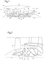
- FIG. 2 An exemplary arrangement for a geared fan gas turbine engine 10 is shown in Figure 2 .
- the low pressure turbine 19 (see Figure 1 ) drives the shaft 26, which is coupled to a sun wheel, or sun gear, 28 of the epicyclic gear arrangement 30.
- a sun wheel, or sun gear, 28 of the epicyclic gear arrangement 30 Radially outwardly of the sun gear 28 and intermeshing therewith is a plurality of planet gears 32 that are coupled together by a planet carrier 34.
- the planet carrier 34 constrains the planet gears 32 to process around the sun gear 28 in synchronicity whilst enabling each planet gear 32 to rotate about its own axis.
- the planet carrier 34 is coupled via linkages 36 to the fan 23 in order to drive its rotation about the engine axis 9.
- an annulus or ring gear 38 Radially outwardly of the planet gears 32 and intermeshing therewith is an annulus or ring gear 38 that is coupled, via linkages 40, to a stationary supporting structure 24.
- low pressure turbine and “low pressure compressor” as used herein may be taken to mean the lowest pressure turbine stages and lowest pressure compressor stages (i.e. not including the fan 23) respectively and/or the turbine and compressor stages that are connected together by the interconnecting shaft 26 with the lowest rotational speed in the engine (i.e. not including the gearbox output shaft that drives the fan 23).
- the "low pressure turbine” and “low pressure compressor” referred to herein may alternatively be known as the "intermediate pressure turbine” and “intermediate pressure compressor”. Where such alternative nomenclature is used, the fan 23 may be referred to as a first, or lowest pressure, compression stage.
- the epicyclic gearbox 30 is shown by way of example in greater detail in Figure 3 .
- Each of the sun gear 28, planet gears 32 and ring gear 38 comprise teeth about their periphery to intermesh with the other gears. However, for clarity only exemplary portions of the teeth are illustrated in Figure 3 .
- planetary epicyclic gearbox 30 generally comprise at least three planet gears 32.
- the epicyclic gearbox 30 illustrated by way of example in Figures 2 and 3 is of the planetary type, in that the planet carrier 34 is coupled to an output shaft via linkages 36, with the ring gear 38 fixed.
- the epicyclic gearbox 30 may be a star arrangement, in which the planet carrier 34 is held fixed, with the ring (or annulus) gear 38 allowed to rotate. In such an arrangement the fan 23 is driven by the ring gear 38.
- the gearbox 30 may be a differential gearbox in which the ring gear 38 and the planet carrier 34 are both allowed to rotate.
- any suitable arrangement may be used for locating the gearbox 30 in the engine 10 and/or for connecting the gearbox 30 to the engine 10.
- the connections (such as the linkages 36, 40 in the Figure 2 example) between the gearbox 30 and other parts of the engine 10 (such as the input shaft 26, the output shaft and the fixed structure 24) may have any desired degree of stiffness or flexibility.
- any suitable arrangement of the bearings between rotating and stationary parts of the engine may be used, and the disclosure is not limited to the exemplary arrangement of Figure 2 .
- the gearbox 30 has a star arrangement (described above)
- the skilled person would readily understand that the arrangement of output and support linkages and bearing locations would typically be different to that shown by way of example in Figure 2 .
- the present disclosure extends to a gas turbine engine having any arrangement of gearbox styles (for example star or planetary), support structures, input and output shaft arrangement, and bearing locations.
- gearbox styles for example star or planetary
- support structures for example star or planetary
- input and output shaft arrangement for example star or planetary
- bearing locations for example star or planetary
- the gearbox may drive additional and/or alternative components (e.g. the intermediate pressure compressor and/or a booster compressor).
- additional and/or alternative components e.g. the intermediate pressure compressor and/or a booster compressor.
- gas turbine engines to which the present disclosure may be applied may have alternative configurations.
- such engines may have an alternative number of compressors and/or turbines and/or an alternative number of interconnecting shafts.
- the gas turbine engine shown in Figure 1 has a split flow nozzle 18, 20 meaning that the flow through the bypass duct 22 has its own nozzle 18 that is separate to and radially outside the core exhaust nozzle 20.
- this is not limiting, and any aspect of the present disclosure may also apply to engines in which the flow through the bypass duct 22 and the flow through the core 11 are mixed, or combined, before (or upstream of) a single nozzle, which may be referred to as a mixed flow nozzle.
- One or both nozzles may have a fixed or variable area.
- the described example relates to a turbofan engine, the disclosure may apply, for example, to any type of gas turbine engine, such as an open rotor (in which the fan stage is not surrounded by a nacelle) or turboprop engine, for example.
- the gas turbine engine 10 may not comprise a gearbox 30.
- the geometry of the gas turbine engine 10, and components thereof, is defined by a conventional axis system, comprising an axial direction (which is aligned with the rotational axis 9), a radial direction (in the bottom-to-top direction in Figure 1 ), and a circumferential direction (perpendicular to the page in the Figure 1 view).
- the axial, radial and circumferential directions are mutually perpendicular.
- Figure 4 shows a schematic example of a component 40 that may present inside a gas turbine engine 10 as discussed above.
- the component may be a turbine blade of the gas turbine engine 10.
- the component 40 may be formed from a metal alloy, for example nickel, and the manufacturing process for the component 40 may be intended to result in a single crystal alloy.
- the component 40 may comprise a first crystal grain region 41.
- the first crystal grain may be the intended crystal grain from which the component 40 is to be formed.
- the first crystal grain region 41 has a particular crystal grain axis 410.
- the first crystal grain region 41 may be the only crystal grain present in the component 40.
- a second crystal grain region 42 may also be present in the component 40.
- the second crystal grain region 42 has a crystal grain axis 420 that is different to the crystal grain axis 410 of the first crystal grain region 41.
- the presence of the second crystal grain region 42 may be considered a defect.
- the presence of the defect may be due to an error in the manufacturing process of the component 40.
- the presence of defects may be unavoidable but it may be desirable to reduce the presence of defects in the component 40.
- gamma prime precipitate blocks form the optical surface of the component.
- the presence of a second crystal grain 42 at the surface of the component 40 may cause a change in behaviour of light illuminating the component 40.
- the difference in the angle of the crystal grain axis 420 of the second crystal grain region 42 to the crystal grain axis 410 of the first crystal grain region 41 (known as the sheer angle) may cause a shift in the angular position of maximum reflectance from the surface of the component 40.
- the gamma prime precipitate blocks which form the surface of the component 40 may have a similar size distribution to the wavelength of light used to illuminate the surface.
- the surface of the component 40 may exhibit diffraction grating like properties.
- the presence of a second crystal grain region 42 at a different crystal grain axis 420 results in an in-plain rotation of the diffraction grating like surface, which causes a polarisation shift in light reflected from the surface. Therefore, the presence of a second crystal grain region 42 may cause a change in the polarisation angle of light illuminating the surface of the component 40 when compared to light illuminating the first crystal grain region 41.
- a first image of the component 40 is obtained.
- the component 40 is illuminated with light of a first polarisation state and a first image of the component 40 is recorded by a detector array comprising a plurality of pixels, where the first image includes polarisation data such as the polarisation angle recorded for each pixel.
- a second image of the component 40 is obtained.
- the component 40 is illuminated using light of a second polarisation state which is different to the first polarisation state.
- the second image also includes polarisation data such as the polarisation angle recorded for each pixel.
- both the first polarisation state used to obtain the first image and the second polarisation state used to obtain the second image may be linear polarisation states.
- the polarisation angle of the first state may be different to the second state.
- one of the states may be a circular polarisation state. Different polarisation states may be used depending on the nature of the defect and the component being analysed.
- a difference in polarisation is calculated.
- the first image of the component 40 and the second image of the component 40 are compared.
- a plurality of pixels in the first image may be compared to corresponding pixels of the second image.
- Corresponding pixels may be pixels from each image that represent the same point on the surface of the component 40.
- a difference in the measured polarisation between corresponding pixels may be calculated.
- the change in the recorded polarisation angle between the corresponding pixels may be calculated.
- pixels corresponding to the second crystal grain region 42 may be determined based on the calculated difference in polarisation.
- regions of the second crystal grain region 42 which may be a defect in the component 40 as discussed above, can be identified. Identification of various properties of such defect regions may allow selection of components with minimal or no defects. Identification of the properties may allow improvement of the manufacturing method of the component 40 by comparing the properties defects between different components manufactured using different methods.
- the different regions in the component 40 may be identified in different ways. For example, particular regions of the component 40 may be characterised as being part of the first region 41 if the calculated polarisation difference falls into a first range. Particular regions of the component 40 may be characterised as being part of the second region 42 if the calculated polarisation difference falls into a second range. Alternatively, a region of the image may be categorised as being part of the second region 42 if the calculated in polarisation exceeds a threshold value.
- the calculated difference in polarisation may be used to determine further information about the second crystal grain region 42.
- the calculated difference in polarisation may be used to calculate the angle of orientation of the second crystal grain axis 420 relative to the angle of orientation of the first crystal grain axis 410.
- the boundary between the two regions may also be determined.
- the area of the second crystal grain region 42, either as an absolute value or relative to the area of the first crystal grain region 41 may also be obtained.
- Each of the first image and the second image may be obtained with at least one of the illumination source and the light receiver arranged at the same orientation relative to the component 40.
- identifying corresponding pixels in the first and the second images may be simpler as corresponding pixels will be at the same location in each image.
- Additional information may be used to assist with the identification of the second crystal grain region 42.
- intensity data may also be obtained for each pixel.
- a difference in intensity between different pixels within the first image or corresponding pixels of the first image and the second image may be calculated.
- the calculated difference in intensity may be used in addition to the calculated difference in polarisation when determining the properties of the second crystal grain region 42 as discussed above.
- the method discussed above is not limited to the obtaining of only two images. Any number of images may be obtained, where each of the further plurality of images is obtained using a different polarisation state of light to each of the other plurality of images. For example, a plurality of images may be obtained, where linearly polarised light is used to illuminate the object 40 and the polarisation angle of the light is stepped through in each subsequent image.
- the polarisation values of each of the pixels of the plurality of images may be stored as a matrix of image data. Identification of pixels corresponding to the second crystal grain region 42 may be performed by analysis of the matrix of image data. Data mining and deep learning techniques such as the analysis of the matrix of image data using trained neural networks may be used.
- Figure 6 shows a non-claimed schematic example of apparatus 60 which may be used to perform the method discussed above.
- a light source 61 is used to illuminate the component 40 in a plane of incidence.
- the light source 61 is capable of producing polarised light in various polarisation states, such as linear polarisation states at different angles and circular polarisation states as discussed above.
- the light reaches the component 40, is reflected in the plane of incidence and is received by a detector 62.
- the detector 62 comprises a sensor with multiple pixels, where in each pixel is configured to detect the polarisation state of light incident on the pixel.
- Image data obtained by the detector 62 is passed to an analyser 63.
- the analyser 63 compares the image data of multiple images obtained by the detector 62 to calculate the differences in polarisation as discussed above.
Landscapes
- General Physics & Mathematics (AREA)
- Chemical & Material Sciences (AREA)
- Physics & Mathematics (AREA)
- Health & Medical Sciences (AREA)
- Life Sciences & Earth Sciences (AREA)
- Engineering & Computer Science (AREA)
- Biochemistry (AREA)
- General Health & Medical Sciences (AREA)
- Immunology (AREA)
- Pathology (AREA)
- Analytical Chemistry (AREA)
- Mechanical Engineering (AREA)
- General Engineering & Computer Science (AREA)
- Spectroscopy & Molecular Physics (AREA)
- Food Science & Technology (AREA)
- Medicinal Chemistry (AREA)
- Crystallography & Structural Chemistry (AREA)
- Quality & Reliability (AREA)
- Computer Vision & Pattern Recognition (AREA)
- Theoretical Computer Science (AREA)
- Structures Of Non-Positive Displacement Pumps (AREA)
- Turbine Rotor Nozzle Sealing (AREA)
Claims (15)
- Verfahren zum Analysieren einer Komponente (40), die aus einer Metalllegierung gebildet ist, um einen möglichen Defekt zu identifizieren, wobei die Metalllegierung einen ersten Kristallkornbereich (41) umfasst und der mögliche Defekt einen zweiten Kristallkornbereich (42) umfasst, der auf einer anderen Achse als der erste Kristallkornbereich (41) ausgerichtet ist, wobei das Verfahren die folgenden Schritte umfasst:Erlangen eines ersten Bilds der Komponente (40) unter Verwendung eines Mehrpixelsensors und bei Beleuchtung mit einem ersten Polarisationszustand des Lichts, wobei das erste Bild erste Polarisationsdaten über eine Vielzahl von Pixeln innerhalb des Mehrpixelsensors umfasst; undErlangen eines zweiten Bilds der Komponente (40) unter Verwendung eines Mehrpixelsensors und bei Beleuchtung mit einem zweiten Polarisationszustand des Lichts, der sich von dem ersten Polarisationszustand unterscheidet, wobei das zweite Bild zweite Polarisationsdaten über eine Vielzahl von Pixeln innerhalb des Mehrpixelsensors umfasst;dadurch gekennzeichnet, dass das Verfahren ferner die folgenden Schritte umfasst:Bestimmen einer Differenz zwischen den ersten und den zweiten Polarisationsdaten für die Vielzahl von Pixeln des ersten Bilds und eine entsprechende Vielzahl von Pixeln des zweiten Bilds; undIdentifizieren von Pixeln, die dem zweiten Kristallkornbereich (42) entsprechen, basierend auf der Differenz zwischen ersten Polarisationsdaten von der Vielzahl von Pixeln des ersten Bildes und zweiten Polarisationsdaten der entsprechenden Vielzahl von Pixeln des zweiten Bildes.
- Verfahren nach Anspruch 1, wobei ein Pixel als dem ersten Kristallkornbereich (41) entsprechend kategorisiert wird, wenn die Differenz zwischen ersten Polarisationsdaten von der Vielzahl von Pixeln des ersten Bildes und zweiten Polarisationsdaten der entsprechenden Vielzahl von Pixeln des zweiten Bildes in einen ersten Bereich fällt, oder als dem zweiten Kristallkornbereich (42) entsprechend kategorisiert wird, wenn die Differenz zwischen ersten Polarisationsdaten von der Vielzahl von Pixeln des ersten Bildes und zweiten Polarisationsdaten der entsprechenden Vielzahl von Pixeln des zweiten Bildes in einen zweiten Bereich fällt, wobei sich der erste Bereich von dem zweiten Bereich unterscheidet.
- Verfahren nach Anspruch 1 oder Anspruch 2, wobei ein Pixel als dem zweiten Kristallkornbereich (42) entsprechend kategorisiert wird, wenn die Differenz zwischen den ersten und den zweiten Polarisationsdaten einen Schwellenwert überschreitet.
- Verfahren nach einem vorhergehenden Anspruch, ferner umfassend Bestimmen des Orientierungswinkels des zweiten Kristallkornbereichs (42) relativ zu dem Orientierungswinkel des ersten Kristallkornbereichs (41) basierend auf der Differenz zwischen den ersten und den zweiten Polarisationsdaten.
- Verfahren nach einem vorhergehenden Anspruch, ferner umfassend Bestimmen der Position der Grenze zwischen dem zweiten Kristallkornbereich (42) und dem ersten Kristallkornbereich (41) basierend auf der Differenz zwischen den ersten und den zweiten Polarisationsdaten.
- Verfahren nach einem vorhergehenden Anspruch, ferner umfassend Bestimmen der Fläche des zweiten Kristallkornbereichs (42) basierend auf der Differenz zwischen den ersten und den zweiten Polarisationsdaten.
- Verfahren nach einem vorhergehenden Anspruch, wobei die Komponente (40) unter Verwendung des ersten Polarisationszustands des Lichts in derselben Perspektive und mit derselben Orientierung relativ zu der Beleuchtung unter Verwendung des zweiten Polarisationszustands des Lichts beleuchtet wird.
- Verfahren nach einem vorhergehenden Anspruch, wobei das zweite Bild in derselben Perspektive und Orientierung relativ zu der Komponente wie das erste Bild erlangt wird.
- Verfahren nach einem vorhergehenden Anspruch, wobei mindestens einer von dem ersten und dem zweiten Polarisationszustand des Lichts ein linearer Polarisationszustand ist.
- Verfahren nach Anspruch 9, wobei sowohl der erste als auch der zweite Polarisationszustand des Lichts lineare Polarisationszustände sind und in einer Einfallsebene auf die Komponente einfallen, wobei der erste lineare Polarisationszustand in Bezug auf die Einfallsebene einen anderen Polarisationswinkel aufweist als der zweite lineare Polarisationszustand.
- Verfahren nach einem der Ansprüche 1 bis 8, wobei mindestens einer von dem ersten und dem zweiten Polarisationszustand ein zirkularer Polarisationszustand ist.
- Verfahren nach einem vorhergehenden Anspruch, wobei jedes von dem ersten Bild und dem zweiten Bild ferner Intensitätsdaten umfasst; unddas Verfahren ferner den Schritt eines Bestimmens einer Intensitätsdifferenz für mehrere Pixel des ersten Bildes zwischen jedem Pixel des ersten Bildes und einem entsprechenden Pixel des zweiten Bildes umfasst;wobei die Identifizierung von Pixeln, die dem zweiten Kristallkornbereich (42) entsprechen, zusätzlich auf der Intensitätsdifferenz basiert.
- Verfahren nach einem vorhergehenden Anspruch, ferner umfassend Erlangen einer Vielzahl weiterer Bilder der Komponente (40), wobei jedes der weiteren Vielzahl von Bildern unter Verwendung eines anderen Polarisationszustands als jedes des anderen der weiteren Vielzahl von Bildern erlangt wird; undSpeichern der Polarisationsdaten jedes der Bilder der Komponente in einer Bilddatenmatrix;wobei die Identifizierung von dem zweiten Kristallkornbereich (42) entsprechenden Pixeln durch Analyse der Bilddatenmatrix durchgeführt wird.
- Verfahren nach einem vorhergehenden Anspruch, wobei die Komponente (40) eine Komponente eines Gasturbinentriebwerks ist.
- Verfahren nach Anspruch 14, wobei die Komponente (40) eine Turbinenschaufel ist.
Applications Claiming Priority (1)
| Application Number | Priority Date | Filing Date | Title |
|---|---|---|---|
| GBGB1911749.8A GB201911749D0 (en) | 2019-08-16 | 2019-08-16 | Method and apparatus for analysis a component |
Publications (2)
| Publication Number | Publication Date |
|---|---|
| EP3779407A1 EP3779407A1 (de) | 2021-02-17 |
| EP3779407B1 true EP3779407B1 (de) | 2024-11-20 |
Family
ID=68099440
Family Applications (1)
| Application Number | Title | Priority Date | Filing Date |
|---|---|---|---|
| EP20187412.0A Active EP3779407B1 (de) | 2019-08-16 | 2020-07-23 | Verfahren zur analyse einer komponente |
Country Status (3)
| Country | Link |
|---|---|
| US (1) | US11125679B2 (de) |
| EP (1) | EP3779407B1 (de) |
| GB (1) | GB201911749D0 (de) |
Families Citing this family (4)
| Publication number | Priority date | Publication date | Assignee | Title |
|---|---|---|---|---|
| GB201900583D0 (en) * | 2019-01-16 | 2019-03-06 | Rolls Royce Plc | Method of detecting an anomaly in a single crystal structure |
| GB201910587D0 (en) | 2019-07-24 | 2019-09-04 | Rolls Royce Plc | Defining parameters for scan of single crystal structure |
| FR3125126B1 (fr) * | 2021-07-12 | 2024-03-08 | Safran | Procédé de contrôle des défauts de surface d’une pièce de fonderie en métal monocristallin et système de mise en œuvre |
| FR3149089B1 (fr) * | 2023-05-24 | 2025-04-18 | Safran | Procede de controle non destructif de la qualite d’une piece constituee d’un superalliage base nickel |
Family Cites Families (11)
| Publication number | Priority date | Publication date | Assignee | Title |
|---|---|---|---|---|
| JPH04102049A (ja) | 1990-08-22 | 1992-04-03 | Fujitsu Ltd | 超伝導体薄膜の評価方法および超伝導デバイスの製造方法 |
| JPH0566381A (ja) | 1991-09-09 | 1993-03-19 | Olympus Optical Co Ltd | 光沢検出装置 |
| JPH05180775A (ja) | 1992-01-06 | 1993-07-23 | Kawasaki Steel Corp | 電動ステージ付画像処理装置 |
| US5426506A (en) * | 1993-03-22 | 1995-06-20 | The University Of Chicago | Optical method and apparatus for detection of surface and near-subsurface defects in dense ceramics |
| US6678057B2 (en) | 2001-12-19 | 2004-01-13 | General Electric Company | Method and device for reduction in noise in images from shiny parts |
| US7034931B2 (en) * | 2003-06-30 | 2006-04-25 | United Technologies Corporation | Method to grain inspect directionally solidified castings |
| JP5701392B2 (ja) * | 2010-10-12 | 2015-04-15 | インディアン インスティテュート オブ テクノロジー カーンプル | サンプルの特性を画像化し、サンプル内の損傷の領域を識別するシステムおよび方法 |
| GB201315912D0 (en) | 2013-09-06 | 2013-10-23 | Rolls Royce Plc | Apparatus and method for inspecting an article |
| GB201315910D0 (en) | 2013-09-06 | 2013-10-23 | Rolls Royce Plc | Apparatus and method for inspecting an article |
| GB201518322D0 (en) | 2015-10-16 | 2015-12-02 | Rolls Royce Plc | A method for classifying a defect in a component intended to have a monocrystalline |
| US11867891B2 (en) * | 2016-12-22 | 2024-01-09 | Advanced Optical Technologies, Inc. | Polarimeter with multiple independent tunable channels and method for material orientation imaging |
-
2019
- 2019-08-16 GB GBGB1911749.8A patent/GB201911749D0/en not_active Ceased
-
2020
- 2020-07-15 US US16/929,144 patent/US11125679B2/en active Active
- 2020-07-23 EP EP20187412.0A patent/EP3779407B1/de active Active
Also Published As
| Publication number | Publication date |
|---|---|
| EP3779407A1 (de) | 2021-02-17 |
| US11125679B2 (en) | 2021-09-21 |
| GB201911749D0 (en) | 2019-10-02 |
| US20210048384A1 (en) | 2021-02-18 |
Similar Documents
| Publication | Publication Date | Title |
|---|---|---|
| EP3779407B1 (de) | Verfahren zur analyse einer komponente | |
| US10436035B1 (en) | Fan design | |
| US20200173456A1 (en) | Geared turbofan engine | |
| EP3734016A1 (de) | Gasturbinenmotor mit lüfterauslassleitschaufeln | |
| US20220275763A1 (en) | Gas turbine engine | |
| EP3671132A1 (de) | Wellenüberwachungssystem | |
| EP3789602A1 (de) | Effizienter strahl | |
| EP3734022A1 (de) | Gasturbinentriebwerk | |
| US11561235B2 (en) | Shaft monitoring system | |
| US11268440B2 (en) | Stabilization bearing system for geared turbofan engines | |
| EP3667022A1 (de) | Eiskristallschutz für ein turbostrahltriebwerk | |
| EP3822452B1 (de) | Gasturbinentriebwerk | |
| US11099143B2 (en) | Method of detecting an anomaly in a single crystal structure | |
| US10677169B1 (en) | Fan blade retention assembly | |
| EP3798624A1 (de) | Definieren von parametern für die abtastung einer einkristallstruktur | |
| GB2587612A (en) | Ice detection system and method | |
| EP3647576A1 (de) | Gasturbinentriebwerk | |
| US10955045B2 (en) | Planet carrier and method of assembling of a planet carrier | |
| US20200141333A1 (en) | Method of controlling a gas turbine engine | |
| US11156118B2 (en) | Gas turbine engine | |
| EP3734044B1 (de) | Gasturbinentriebwerk mit kernaufhängung | |
| EP3808962A1 (de) | Turbofan und bypass-anordnung | |
| US11268386B2 (en) | Gas turbine engine having optimized fan | |
| EP3741982A1 (de) | Gasturbinentriebwerk | |
| US20190338643A1 (en) | Method for manufacturing a component |
Legal Events
| Date | Code | Title | Description |
|---|---|---|---|
| PUAI | Public reference made under article 153(3) epc to a published international application that has entered the european phase |
Free format text: ORIGINAL CODE: 0009012 |
|
| STAA | Information on the status of an ep patent application or granted ep patent |
Free format text: STATUS: THE APPLICATION HAS BEEN PUBLISHED |
|
| AK | Designated contracting states |
Kind code of ref document: A1 Designated state(s): AL AT BE BG CH CY CZ DE DK EE ES FI FR GB GR HR HU IE IS IT LI LT LU LV MC MK MT NL NO PL PT RO RS SE SI SK SM TR |
|
| AX | Request for extension of the european patent |
Extension state: BA ME |
|
| STAA | Information on the status of an ep patent application or granted ep patent |
Free format text: STATUS: REQUEST FOR EXAMINATION WAS MADE |
|
| 17P | Request for examination filed |
Effective date: 20210806 |
|
| RBV | Designated contracting states (corrected) |
Designated state(s): AL AT BE BG CH CY CZ DE DK EE ES FI FR GB GR HR HU IE IS IT LI LT LU LV MC MK MT NL NO PL PT RO RS SE SI SK SM TR |
|
| STAA | Information on the status of an ep patent application or granted ep patent |
Free format text: STATUS: EXAMINATION IS IN PROGRESS |
|
| 17Q | First examination report despatched |
Effective date: 20230330 |
|
| GRAP | Despatch of communication of intention to grant a patent |
Free format text: ORIGINAL CODE: EPIDOSNIGR1 |
|
| STAA | Information on the status of an ep patent application or granted ep patent |
Free format text: STATUS: GRANT OF PATENT IS INTENDED |
|
| GRAS | Grant fee paid |
Free format text: ORIGINAL CODE: EPIDOSNIGR3 |
|
| GRAA | (expected) grant |
Free format text: ORIGINAL CODE: 0009210 |
|
| STAA | Information on the status of an ep patent application or granted ep patent |
Free format text: STATUS: THE PATENT HAS BEEN GRANTED |
|
| RIC1 | Information provided on ipc code assigned before grant |
Ipc: G01N 33/2045 20190101ALN20240918BHEP Ipc: G01N 21/84 20060101ALN20240918BHEP Ipc: G06T 7/00 20170101ALI20240918BHEP Ipc: F01D 21/00 20060101ALI20240918BHEP Ipc: G01N 21/95 20060101ALI20240918BHEP Ipc: G01N 21/88 20060101ALI20240918BHEP Ipc: G01N 21/21 20060101AFI20240918BHEP |
|
| RIC1 | Information provided on ipc code assigned before grant |
Ipc: G01N 33/2045 20190101ALN20240920BHEP Ipc: G01N 21/84 20060101ALN20240920BHEP Ipc: G06T 7/00 20170101ALI20240920BHEP Ipc: F01D 21/00 20060101ALI20240920BHEP Ipc: G01N 21/95 20060101ALI20240920BHEP Ipc: G01N 21/88 20060101ALI20240920BHEP Ipc: G01N 21/21 20060101AFI20240920BHEP |
|
| INTG | Intention to grant announced |
Effective date: 20241002 |
|
| P01 | Opt-out of the competence of the unified patent court (upc) registered |
Free format text: CASE NUMBER: APP_55503/2024 Effective date: 20241009 |
|
| AK | Designated contracting states |
Kind code of ref document: B1 Designated state(s): AL AT BE BG CH CY CZ DE DK EE ES FI FR GB GR HR HU IE IS IT LI LT LU LV MC MK MT NL NO PL PT RO RS SE SI SK SM TR |
|
| REG | Reference to a national code |
Ref country code: GB Ref legal event code: FG4D |
|
| REG | Reference to a national code |
Ref country code: CH Ref legal event code: EP |
|
| REG | Reference to a national code |
Ref country code: DE Ref legal event code: R096 Ref document number: 602020041558 Country of ref document: DE |
|
| REG | Reference to a national code |
Ref country code: IE Ref legal event code: FG4D |
|
| REG | Reference to a national code |
Ref country code: LT Ref legal event code: MG9D |
|
| REG | Reference to a national code |
Ref country code: NL Ref legal event code: MP Effective date: 20241120 |
|
| PG25 | Lapsed in a contracting state [announced via postgrant information from national office to epo] |
Ref country code: PT Free format text: LAPSE BECAUSE OF FAILURE TO SUBMIT A TRANSLATION OF THE DESCRIPTION OR TO PAY THE FEE WITHIN THE PRESCRIBED TIME-LIMIT Effective date: 20250320 Ref country code: HR Free format text: LAPSE BECAUSE OF FAILURE TO SUBMIT A TRANSLATION OF THE DESCRIPTION OR TO PAY THE FEE WITHIN THE PRESCRIBED TIME-LIMIT Effective date: 20241120 Ref country code: IS Free format text: LAPSE BECAUSE OF FAILURE TO SUBMIT A TRANSLATION OF THE DESCRIPTION OR TO PAY THE FEE WITHIN THE PRESCRIBED TIME-LIMIT Effective date: 20250320 |
|
| PG25 | Lapsed in a contracting state [announced via postgrant information from national office to epo] |
Ref country code: FI Free format text: LAPSE BECAUSE OF FAILURE TO SUBMIT A TRANSLATION OF THE DESCRIPTION OR TO PAY THE FEE WITHIN THE PRESCRIBED TIME-LIMIT Effective date: 20241120 Ref country code: NL Free format text: LAPSE BECAUSE OF FAILURE TO SUBMIT A TRANSLATION OF THE DESCRIPTION OR TO PAY THE FEE WITHIN THE PRESCRIBED TIME-LIMIT Effective date: 20241120 |
|
| REG | Reference to a national code |
Ref country code: AT Ref legal event code: MK05 Ref document number: 1743979 Country of ref document: AT Kind code of ref document: T Effective date: 20241120 |
|
| PG25 | Lapsed in a contracting state [announced via postgrant information from national office to epo] |
Ref country code: BG Free format text: LAPSE BECAUSE OF FAILURE TO SUBMIT A TRANSLATION OF THE DESCRIPTION OR TO PAY THE FEE WITHIN THE PRESCRIBED TIME-LIMIT Effective date: 20241120 |
|
| PG25 | Lapsed in a contracting state [announced via postgrant information from national office to epo] |
Ref country code: ES Free format text: LAPSE BECAUSE OF FAILURE TO SUBMIT A TRANSLATION OF THE DESCRIPTION OR TO PAY THE FEE WITHIN THE PRESCRIBED TIME-LIMIT Effective date: 20241120 |
|
| PG25 | Lapsed in a contracting state [announced via postgrant information from national office to epo] |
Ref country code: NO Free format text: LAPSE BECAUSE OF FAILURE TO SUBMIT A TRANSLATION OF THE DESCRIPTION OR TO PAY THE FEE WITHIN THE PRESCRIBED TIME-LIMIT Effective date: 20250220 |
|
| PG25 | Lapsed in a contracting state [announced via postgrant information from national office to epo] |
Ref country code: LV Free format text: LAPSE BECAUSE OF FAILURE TO SUBMIT A TRANSLATION OF THE DESCRIPTION OR TO PAY THE FEE WITHIN THE PRESCRIBED TIME-LIMIT Effective date: 20241120 Ref country code: GR Free format text: LAPSE BECAUSE OF FAILURE TO SUBMIT A TRANSLATION OF THE DESCRIPTION OR TO PAY THE FEE WITHIN THE PRESCRIBED TIME-LIMIT Effective date: 20250221 Ref country code: AT Free format text: LAPSE BECAUSE OF FAILURE TO SUBMIT A TRANSLATION OF THE DESCRIPTION OR TO PAY THE FEE WITHIN THE PRESCRIBED TIME-LIMIT Effective date: 20241120 |
|
| PG25 | Lapsed in a contracting state [announced via postgrant information from national office to epo] |
Ref country code: PL Free format text: LAPSE BECAUSE OF FAILURE TO SUBMIT A TRANSLATION OF THE DESCRIPTION OR TO PAY THE FEE WITHIN THE PRESCRIBED TIME-LIMIT Effective date: 20241120 |
|
| PG25 | Lapsed in a contracting state [announced via postgrant information from national office to epo] |
Ref country code: RS Free format text: LAPSE BECAUSE OF FAILURE TO SUBMIT A TRANSLATION OF THE DESCRIPTION OR TO PAY THE FEE WITHIN THE PRESCRIBED TIME-LIMIT Effective date: 20250220 |
|
| PG25 | Lapsed in a contracting state [announced via postgrant information from national office to epo] |
Ref country code: SM Free format text: LAPSE BECAUSE OF FAILURE TO SUBMIT A TRANSLATION OF THE DESCRIPTION OR TO PAY THE FEE WITHIN THE PRESCRIBED TIME-LIMIT Effective date: 20241120 |
|
| PG25 | Lapsed in a contracting state [announced via postgrant information from national office to epo] |
Ref country code: DK Free format text: LAPSE BECAUSE OF FAILURE TO SUBMIT A TRANSLATION OF THE DESCRIPTION OR TO PAY THE FEE WITHIN THE PRESCRIBED TIME-LIMIT Effective date: 20241120 |
|
| PG25 | Lapsed in a contracting state [announced via postgrant information from national office to epo] |
Ref country code: EE Free format text: LAPSE BECAUSE OF FAILURE TO SUBMIT A TRANSLATION OF THE DESCRIPTION OR TO PAY THE FEE WITHIN THE PRESCRIBED TIME-LIMIT Effective date: 20241120 |
|
| PG25 | Lapsed in a contracting state [announced via postgrant information from national office to epo] |
Ref country code: RO Free format text: LAPSE BECAUSE OF FAILURE TO SUBMIT A TRANSLATION OF THE DESCRIPTION OR TO PAY THE FEE WITHIN THE PRESCRIBED TIME-LIMIT Effective date: 20241120 |
|
| PG25 | Lapsed in a contracting state [announced via postgrant information from national office to epo] |
Ref country code: SK Free format text: LAPSE BECAUSE OF FAILURE TO SUBMIT A TRANSLATION OF THE DESCRIPTION OR TO PAY THE FEE WITHIN THE PRESCRIBED TIME-LIMIT Effective date: 20241120 |
|
| PG25 | Lapsed in a contracting state [announced via postgrant information from national office to epo] |
Ref country code: CZ Free format text: LAPSE BECAUSE OF FAILURE TO SUBMIT A TRANSLATION OF THE DESCRIPTION OR TO PAY THE FEE WITHIN THE PRESCRIBED TIME-LIMIT Effective date: 20241120 |
|
| PG25 | Lapsed in a contracting state [announced via postgrant information from national office to epo] |
Ref country code: IT Free format text: LAPSE BECAUSE OF FAILURE TO SUBMIT A TRANSLATION OF THE DESCRIPTION OR TO PAY THE FEE WITHIN THE PRESCRIBED TIME-LIMIT Effective date: 20241120 |
|
| REG | Reference to a national code |
Ref country code: DE Ref legal event code: R097 Ref document number: 602020041558 Country of ref document: DE |
|
| PG25 | Lapsed in a contracting state [announced via postgrant information from national office to epo] |
Ref country code: SE Free format text: LAPSE BECAUSE OF FAILURE TO SUBMIT A TRANSLATION OF THE DESCRIPTION OR TO PAY THE FEE WITHIN THE PRESCRIBED TIME-LIMIT Effective date: 20241120 |
|
| PLBE | No opposition filed within time limit |
Free format text: ORIGINAL CODE: 0009261 |
|
| STAA | Information on the status of an ep patent application or granted ep patent |
Free format text: STATUS: NO OPPOSITION FILED WITHIN TIME LIMIT |
|
| PGFP | Annual fee paid to national office [announced via postgrant information from national office to epo] |
Ref country code: DE Payment date: 20250728 Year of fee payment: 6 |
|
| PGFP | Annual fee paid to national office [announced via postgrant information from national office to epo] |
Ref country code: GB Payment date: 20250722 Year of fee payment: 6 |
|
| PGFP | Annual fee paid to national office [announced via postgrant information from national office to epo] |
Ref country code: FR Payment date: 20250725 Year of fee payment: 6 |
|
| 26N | No opposition filed |
Effective date: 20250821 |