EP3779383A1 - Bead stringing apparatus for linear thermal sensors - Google Patents
Bead stringing apparatus for linear thermal sensors Download PDFInfo
- Publication number
- EP3779383A1 EP3779383A1 EP19212732.2A EP19212732A EP3779383A1 EP 3779383 A1 EP3779383 A1 EP 3779383A1 EP 19212732 A EP19212732 A EP 19212732A EP 3779383 A1 EP3779383 A1 EP 3779383A1
- Authority
- EP
- European Patent Office
- Prior art keywords
- worm gear
- diaphragm
- wire
- diaphragms
- bead
- Prior art date
- Legal status (The legal status is an assumption and is not a legal conclusion. Google has not performed a legal analysis and makes no representation as to the accuracy of the status listed.)
- Granted
Links
Images


Classifications
-
- G—PHYSICS
- G01—MEASURING; TESTING
- G01K—MEASURING TEMPERATURE; MEASURING QUANTITY OF HEAT; THERMALLY-SENSITIVE ELEMENTS NOT OTHERWISE PROVIDED FOR
- G01K1/00—Details of thermometers not specially adapted for particular types of thermometer
- G01K1/08—Protective devices, e.g. casings
-
- G—PHYSICS
- G01—MEASURING; TESTING
- G01K—MEASURING TEMPERATURE; MEASURING QUANTITY OF HEAT; THERMALLY-SENSITIVE ELEMENTS NOT OTHERWISE PROVIDED FOR
- G01K5/00—Measuring temperature based on the expansion or contraction of a material
- G01K5/48—Measuring temperature based on the expansion or contraction of a material the material being a solid
- G01K5/56—Measuring temperature based on the expansion or contraction of a material the material being a solid constrained so that expansion or contraction causes a deformation of the solid
- G01K5/58—Measuring temperature based on the expansion or contraction of a material the material being a solid constrained so that expansion or contraction causes a deformation of the solid the solid body being constrained at more than one point, e.g. rod, plate, diaphragm
-
- B—PERFORMING OPERATIONS; TRANSPORTING
- B23—MACHINE TOOLS; METAL-WORKING NOT OTHERWISE PROVIDED FOR
- B23P—METAL-WORKING NOT OTHERWISE PROVIDED FOR; COMBINED OPERATIONS; UNIVERSAL MACHINE TOOLS
- B23P19/00—Machines for simply fitting together or separating metal parts or objects, or metal and non-metal parts, whether or not involving some deformation; Tools or devices therefor so far as not provided for in other classes
-
- B—PERFORMING OPERATIONS; TRANSPORTING
- B23—MACHINE TOOLS; METAL-WORKING NOT OTHERWISE PROVIDED FOR
- B23P—METAL-WORKING NOT OTHERWISE PROVIDED FOR; COMBINED OPERATIONS; UNIVERSAL MACHINE TOOLS
- B23P19/00—Machines for simply fitting together or separating metal parts or objects, or metal and non-metal parts, whether or not involving some deformation; Tools or devices therefor so far as not provided for in other classes
- B23P19/001—Article feeders for assembling machines
-
- B—PERFORMING OPERATIONS; TRANSPORTING
- B23—MACHINE TOOLS; METAL-WORKING NOT OTHERWISE PROVIDED FOR
- B23P—METAL-WORKING NOT OTHERWISE PROVIDED FOR; COMBINED OPERATIONS; UNIVERSAL MACHINE TOOLS
- B23P19/00—Machines for simply fitting together or separating metal parts or objects, or metal and non-metal parts, whether or not involving some deformation; Tools or devices therefor so far as not provided for in other classes
- B23P19/001—Article feeders for assembling machines
- B23P19/004—Feeding the articles from hoppers to machines or dispensers
-
- B—PERFORMING OPERATIONS; TRANSPORTING
- B23—MACHINE TOOLS; METAL-WORKING NOT OTHERWISE PROVIDED FOR
- B23P—METAL-WORKING NOT OTHERWISE PROVIDED FOR; COMBINED OPERATIONS; UNIVERSAL MACHINE TOOLS
- B23P19/00—Machines for simply fitting together or separating metal parts or objects, or metal and non-metal parts, whether or not involving some deformation; Tools or devices therefor so far as not provided for in other classes
- B23P19/008—Machines for simply fitting together or separating metal parts or objects, or metal and non-metal parts, whether or not involving some deformation; Tools or devices therefor so far as not provided for in other classes the parts being continuously transported through the machine during assembling or disassembling
-
- H—ELECTRICITY
- H01—ELECTRIC ELEMENTS
- H01B—CABLES; CONDUCTORS; INSULATORS; SELECTION OF MATERIALS FOR THEIR CONDUCTIVE, INSULATING OR DIELECTRIC PROPERTIES
- H01B17/00—Insulators or insulating bodies characterised by their form
- H01B17/56—Insulating bodies
- H01B17/58—Tubes, sleeves, beads, or bobbins through which the conductor passes
-
- D—TEXTILES; PAPER
- D04—BRAIDING; LACE-MAKING; KNITTING; TRIMMINGS; NON-WOVEN FABRICS
- D04D—TRIMMINGS; RIBBONS, TAPES OR BANDS, NOT OTHERWISE PROVIDED FOR
- D04D1/00—Ropes or like decorative or ornamental elongated trimmings made from filamentary material
- D04D1/04—Ropes or like decorative or ornamental elongated trimmings made from filamentary material by threading or stringing pearls or beads on filamentary material
-
- G—PHYSICS
- G01—MEASURING; TESTING
- G01K—MEASURING TEMPERATURE; MEASURING QUANTITY OF HEAT; THERMALLY-SENSITIVE ELEMENTS NOT OTHERWISE PROVIDED FOR
- G01K7/00—Measuring temperature based on the use of electric or magnetic elements directly sensitive to heat ; Power supply therefor, e.g. using thermoelectric elements
- G01K7/02—Measuring temperature based on the use of electric or magnetic elements directly sensitive to heat ; Power supply therefor, e.g. using thermoelectric elements using thermoelectric elements, e.g. thermocouples
- G01K7/04—Measuring temperature based on the use of electric or magnetic elements directly sensitive to heat ; Power supply therefor, e.g. using thermoelectric elements using thermoelectric elements, e.g. thermocouples the object to be measured not forming one of the thermoelectric materials
Definitions
- Exemplary embodiments pertain to the art of linear thermal sensors, and more particularly to apparatus and methods of installing insulating media for linear thermal sensors.
- Linear thermal sensors typically use an insulating media that surrounds a center wire and are saturated in a thermal responding chemical material.
- the insulation material is often a ceramic material.
- These linear thermal sensors are biased via the center wire with an outer metal tube designated as the ground reference.
- the current automated manufacturing method for sleeving ceramic media or beads onto a center wire utilizes a feeder, a trough and pulley mechanism and a series of solenoid based contacts to hold and release the ceramic beads along the wire. This approach utilizes a lot of moving parts and is prone to jamming from a number of design weaknesses.
- a sleeving apparatus in one embodiment includes a worm gear.
- the worm gear has a plurality of threads, the worm gear receptive of a bead between adjacent threads of the plurality of threads.
- a plurality of flexible diaphragms are positioned along the worm gear. Each diaphragm of the plurality of diaphragms is configured to position a wire in alignment with a central bead opening of the bead. With rotation of the worm gear about a worm gear axis, the bead advances onto the wire with the wire passing into the central bead opening.
- the plurality of diaphragms are configured to allow passage of the bead through each diaphragm of the plurality of diaphragms.
- each diaphragm of the plurality of diaphragms includes a central diaphragm opening configured to position the wire.
- each diaphragm of the plurality of diaphragms includes a diaphragm rim defining an outer boundary of the diaphragm, and a plurality of flexible members extending inwardly from the diaphragm rim to the central diaphragm opening.
- adjacent diaphragm members are separated at least partially along their length from the diaphragm rim to the central diaphragm opening.
- the plurality of members are configured to move independently.
- the plurality of members is a plurality of flaps.
- the plurality of members vary in size and/or shape.
- the plurality of diaphragms are formed from an elastomeric material.
- the plurality of diaphragms are circular.
- the worm gear is configured such that a pitch between adjacent threads of the plurality of treads is greater than a bead length of the bead.
- a hopper is positioned above the worm gear configured to feed the bead onto the worm gear.
- a spool is configured to receive a sleeved wire.
- a method of installing one or more beads onto a wire includes positioning one or more beads between adjacent threads of a worm gear, positioning a wire along a length of the worm gear via a plurality of flexible diaphragms, rotating the worm gear about a worm gear axis thus advancing the one or more beads onto the wire and urging the one or more beads along the wire and through the plurality of diaphragms via rotation of the worm gear about the worm gear axis.
- the one or more beads are dispensed onto the worm gear from a hopper.
- the wire is supported via a central diaphragm opening in each diaphragm of the plurality of diaphragms, the wire therefore positioned relative to a central bead opening of the one or more beads.
- the one or more beads are advanced onto the wire via the central bead opening.
- the one or more beads are urged through the plurality of diaphragms via a plurality of flexible members formed in each diaphragm of the plurality of diaphragms.
- the plurality of flaps extend from a diaphragm rim to a central diaphragm opening, the plurality of members separated at least partially along their length.
- the worm gear is configured such that a pitch between the adjacent threads is greater than a bead length of the bead.
- the wire and the one or more beads are wound onto a spool.
- FIG. 1 is a partial perspective view of a linear thermal sensor 10.
- the sensor 10 includes one or more wires 12 enclosed in a metallic housing 14 with an insulative layer 16 located between the one or more wires 12 and the metallic housing 14.
- the insulative layer 16 is formed from a plurality of beads 18, in some embodiments ceramic beads 18, strung along the one or more wires 12.
- each of the beads 18 has a central bead opening 20 through which the one or more wires 12 is fed.
- the central bead opening 20 is chamfered to allow for easier feeding of the beads 18 onto the wires 12.
- the beads 18 are sleeved onto the wire 12 via a sleeving apparatus 22.
- the sleeving apparatus 22 includes a hopper 24 into which the beads 18 are held for sleeving.
- the beads 18 are fed from the hopper 24 to a worm gear 26 vertically below the hopper 24.
- the beads 18 drop from the hopper 24 onto the worm gear 26 via a hopper opening 28.
- the worm gear 26 rotates about a gear axis 30 and has a thread pitch 32 greater than a bead length 34 of the bead 18, such that when dropped from the hopper 24 via the hopper opening 28 the bead 18 rests between axially-adjacent threads 36 of the worm gear 26.
- the threads 36 have a thread height large enough to retain the bead 18 between the adjacent threads 36.
- the wire 12 is positioned along the worm gear 26 and as the worm gear 26 is rotated about the gear axis 28, the beads 18 advance toward and onto the wire 12.
- a plurality of diaphragms 38 are located along the worm gear 26 and are configured to position the wire 12 to align the wire 12 with the central bead openings 20 of the beads, while allowing the beads 18 to pass through the diaphragm 38 while the beads 18 advance along the worm gear 26.
- the diaphragms 38 are formed from a flexible material such as an elastomeric material or silicone rubber.
- an exemplary diaphragm 38 includes a diaphragm rim 40 defining an outer boundary of the diaphragm 38.
- the diaphragm rim 40 is formed from a first material and the diaphragm flaps 42 are formed from a second material having reduced stiffness compared to the first material.
- the diaphragm flaps 42 each have a radial length 44 and a circumferential width 46, and adjacent diaphragm flaps 42 are separated at least partially along their radial length 44 allowing the diaphragm flaps 42 to move independently.
- the diaphragm flaps 42 define a central diaphragm opening 48 through which the wire 12 passes.
- the central diaphragm opening 48 positions the wire 12 to align the wire 12 with the central bead openings 20.
- the diaphragm 38 includes a plurality of diaphragm flaps 42, in other embodiments other structures may be utilized.
- the diaphragm 38 may include an array of fibers or bristles extending inwardly from the diaphragm rim 40. The array of fibers or bristles have sufficient flexibility to allow for passage of the bead 18 therethrough, while still positioning the wire 12.
- the bead 20 and wire 12 assembly may be passed along a linear trolley, or alternatively wound onto a spool 46 as shown in FIG. 3 .
- the diaphragm 38 in particular the diaphragm rim 40 is circular. It is to be appreciated, however, that in other embodiments other diaphragm shapes, such as oval, rectangular, triangular or the like may be used.
- the embodiment of FIG. 4 illustrates six diaphragm flaps 42 extending radially inwardly from the diaphragm rim 40 toward the central diaphragm opening 48. It is to be appreciated, however, that other quantities of diaphragm flaps 42, for example, three, eight or more diaphragm flaps 42 may be utilized to provide the desired flexibility and positioning of the wire 12. Further, while in the embodiment of FIG.
- the diaphragm flaps 42 are of unequal size depending on their circumferential position around the central diaphragm opening 48, in other embodiments the diaphragm flaps 42 may be identically shaped. While described herein in the context of manufacturing a linear thermal sensor 10, it is to be appreciated that the sleeving apparatus 22 may be utilized in the manufacture of other articles, in particular articles in which beads are sleeved onto a wire, string, filament or the like.
- a method of manufacturing a linear thermal sensor is illustrated.
- a plurality of beads 18 are placed in a hopper 24.
- the beads 18 are dropped onto a worm gear 26 and positioned between threads of the worm gear 26.
- the worm gear 26 is rotated, thus advancing the beads 18 along the worm gear 26 and onto a wire 12.
- the beads 18 pass through a plurality of flexible diaphragms 38 at block 106.
- the flexible diaphragms 38 are configured to position the wire 12 relative to the central bead openings 20 of the beads 18, while allowing the beads 18 to advance along the worm gear 26 and through the plurality of diaphragms 38.
- the wire 12 and bead 18 assembly is then wound onto a spool.
- worm gear 26 and the diaphragms 38 as disclosed herein results in a manufacturing apparatus and process that is simple, cost effective, and reduces complexity of the sleeving operation of the plurality of beads 18 onto the wire 12. Further, such an apparatus and method significantly reduce the manual operation necessary to perform such an assembly.
Landscapes
- Engineering & Computer Science (AREA)
- Mechanical Engineering (AREA)
- Physics & Mathematics (AREA)
- General Physics & Mathematics (AREA)
- Transmission Devices (AREA)
- Measuring Temperature Or Quantity Of Heat (AREA)
- Investigating Or Analyzing Materials Using Thermal Means (AREA)
Abstract
Description
- Exemplary embodiments pertain to the art of linear thermal sensors, and more particularly to apparatus and methods of installing insulating media for linear thermal sensors.
- Linear thermal sensors typically use an insulating media that surrounds a center wire and are saturated in a thermal responding chemical material. The insulation material is often a ceramic material. These linear thermal sensors are biased via the center wire with an outer metal tube designated as the ground reference.
- Various linear thermal sensor manufacturing techniques such as extrusion of the ceramic media, manual feeding ceramic sleeves and drawing a glass media onto the center wire have all been utilized in practice. Each of them has design limitations associated with fracturing or limitations that restrict reacting chemical distribution due to the manufacturing techniques employed.
- The current automated manufacturing method for sleeving ceramic media or beads onto a center wire utilizes a feeder, a trough and pulley mechanism and a series of solenoid based contacts to hold and release the ceramic beads along the wire. This approach utilizes a lot of moving parts and is prone to jamming from a number of design weaknesses.
- In one embodiment a sleeving apparatus includes a worm gear. The worm gear has a plurality of threads, the worm gear receptive of a bead between adjacent threads of the plurality of threads. A plurality of flexible diaphragms are positioned along the worm gear. Each diaphragm of the plurality of diaphragms is configured to position a wire in alignment with a central bead opening of the bead. With rotation of the worm gear about a worm gear axis, the bead advances onto the wire with the wire passing into the central bead opening. The plurality of diaphragms are configured to allow passage of the bead through each diaphragm of the plurality of diaphragms.
- Additionally or alternatively, in this or other embodiments each diaphragm of the plurality of diaphragms includes a central diaphragm opening configured to position the wire.
- Additionally or alternatively, in this or other embodiments each diaphragm of the plurality of diaphragms includes a diaphragm rim defining an outer boundary of the diaphragm, and a plurality of flexible members extending inwardly from the diaphragm rim to the central diaphragm opening.
- Additionally or alternatively, in this or other embodiments adjacent diaphragm members are separated at least partially along their length from the diaphragm rim to the central diaphragm opening.
- Additionally or alternatively, in this or other embodiments the plurality of members are configured to move independently.
- Additionally or alternatively, in this or other embodiments the plurality of members is a plurality of flaps.
- Additionally or alternatively, in this or other embodiments the plurality of members vary in size and/or shape.
- Additionally or alternatively, in this or other embodiments the plurality of diaphragms are formed from an elastomeric material.
- Additionally or alternatively, in this or other embodiments the plurality of diaphragms are circular.
- Additionally or alternatively, in this or other embodiments the worm gear is configured such that a pitch between adjacent threads of the plurality of treads is greater than a bead length of the bead.
- Additionally or alternatively, in this or other embodiments a hopper is positioned above the worm gear configured to feed the bead onto the worm gear.
- Additionally or alternatively, in this or other embodiments a spool is configured to receive a sleeved wire.
- In another embodiment, a method of installing one or more beads onto a wire includes positioning one or more beads between adjacent threads of a worm gear, positioning a wire along a length of the worm gear via a plurality of flexible diaphragms, rotating the worm gear about a worm gear axis thus advancing the one or more beads onto the wire and urging the one or more beads along the wire and through the plurality of diaphragms via rotation of the worm gear about the worm gear axis.
- Additionally or alternatively, in this or other embodiments the one or more beads are dispensed onto the worm gear from a hopper.
- Additionally or alternatively, in this or other embodiments the wire is supported via a central diaphragm opening in each diaphragm of the plurality of diaphragms, the wire therefore positioned relative to a central bead opening of the one or more beads.
- Additionally or alternatively, in this or other embodiments the one or more beads are advanced onto the wire via the central bead opening.
- Additionally or alternatively, in this or other embodiments the one or more beads are urged through the plurality of diaphragms via a plurality of flexible members formed in each diaphragm of the plurality of diaphragms.
- Additionally or alternatively, in this or other embodiments the plurality of flaps extend from a diaphragm rim to a central diaphragm opening, the plurality of members separated at least partially along their length.
- Additionally or alternatively, in this or other embodiments the worm gear is configured such that a pitch between the adjacent threads is greater than a bead length of the bead.
- Additionally or alternatively, in this or other embodiments the wire and the one or more beads are wound onto a spool.
- The following descriptions should not be considered limiting in any way. With reference to the accompanying drawings, like elements are numbered alike:
-
FIG. 1 is a partial perspective view of an embodiment of a linear thermal sensor; -
FIG. 2 is a cross-sectional view of an insulative bead of a linear thermal sensor; -
FIG. 3 is a schematic view of an embodiment of a sleeving apparatus; -
FIG. 4 is a plan view of an embodiment of a diaphragm for a sleeving apparatus; and -
FIG. 5 is a schematic diagram of an embodiment of a method of manufacturing a linear thermal sensor. - A detailed description of one or more embodiments of the disclosed apparatus and method are presented herein by way of exemplification and not limitation with reference to the Figures.
-
FIG. 1 is a partial perspective view of a linearthermal sensor 10. Thesensor 10 includes one ormore wires 12 enclosed in ametallic housing 14 with aninsulative layer 16 located between the one ormore wires 12 and themetallic housing 14. Theinsulative layer 16 is formed from a plurality ofbeads 18, in some embodimentsceramic beads 18, strung along the one ormore wires 12. Referring toFIG. 2 , each of thebeads 18 has a central bead opening 20 through which the one ormore wires 12 is fed. In some embodiments, the central bead opening 20 is chamfered to allow for easier feeding of thebeads 18 onto thewires 12. - Referring to
FIG. 3 , thebeads 18 are sleeved onto thewire 12 via asleeving apparatus 22. Thesleeving apparatus 22 includes ahopper 24 into which thebeads 18 are held for sleeving. Thebeads 18 are fed from thehopper 24 to aworm gear 26 vertically below thehopper 24. Thebeads 18 drop from thehopper 24 onto theworm gear 26 via a hopper opening 28. Theworm gear 26 rotates about agear axis 30 and has athread pitch 32 greater than abead length 34 of thebead 18, such that when dropped from thehopper 24 via the hopper opening 28 thebead 18 rests between axially-adjacent threads 36 of theworm gear 26. Thethreads 36 have a thread height large enough to retain thebead 18 between theadjacent threads 36. - The
wire 12 is positioned along theworm gear 26 and as theworm gear 26 is rotated about thegear axis 28, thebeads 18 advance toward and onto thewire 12. A plurality ofdiaphragms 38 are located along theworm gear 26 and are configured to position thewire 12 to align thewire 12 with thecentral bead openings 20 of the beads, while allowing thebeads 18 to pass through thediaphragm 38 while thebeads 18 advance along theworm gear 26. In some embodiments, thediaphragms 38 are formed from a flexible material such as an elastomeric material or silicone rubber. - Referring to the plan view of
FIG. 4 , anexemplary diaphragm 38 includes adiaphragm rim 40 defining an outer boundary of thediaphragm 38. A plurality of members, such asdiaphragm flaps 42, extend inwardly from thediaphragm rim 40 toward thewire 12. In some embodiments, thediaphragm rim 40 is formed from a first material and thediaphragm flaps 42 are formed from a second material having reduced stiffness compared to the first material. Thediaphragm flaps 42 each have aradial length 44 and acircumferential width 46, andadjacent diaphragm flaps 42 are separated at least partially along theirradial length 44 allowing thediaphragm flaps 42 to move independently. Thediaphragm flaps 42 define a central diaphragm opening 48 through which thewire 12 passes. The central diaphragm opening 48 positions thewire 12 to align thewire 12 with thecentral bead openings 20. Referring again toFIG. 3 , once thebead 18 is sleeved onto thewire 12, thebead 18 is advanced along thewire 12 by theworm screw 26 and passes through thediaphragms 38 via the flexible diaphragm flaps 42. While in the embodiment ofFIG. 3 and 4 thediaphragm 38 includes a plurality of diaphragm flaps 42, in other embodiments other structures may be utilized. For example, in some embodiments, thediaphragm 38 may include an array of fibers or bristles extending inwardly from thediaphragm rim 40. The array of fibers or bristles have sufficient flexibility to allow for passage of thebead 18 therethrough, while still positioning thewire 12. - Once sleeved onto the
wire 12, thebead 20 andwire 12 assembly may be passed along a linear trolley, or alternatively wound onto aspool 46 as shown inFIG. 3 . - Referring again to
FIG. 4 , in some embodiments thediaphragm 38, in particular thediaphragm rim 40 is circular. It is to be appreciated, however, that in other embodiments other diaphragm shapes, such as oval, rectangular, triangular or the like may be used. Further, the embodiment ofFIG. 4 illustrates sixdiaphragm flaps 42 extending radially inwardly from thediaphragm rim 40 toward thecentral diaphragm opening 48. It is to be appreciated, however, that other quantities of diaphragm flaps 42, for example, three, eight or more diaphragm flaps 42 may be utilized to provide the desired flexibility and positioning of thewire 12. Further, while in the embodiment ofFIG. 4 , the diaphragm flaps 42 are of unequal size depending on their circumferential position around thecentral diaphragm opening 48, in other embodiments the diaphragm flaps 42 may be identically shaped. While described herein in the context of manufacturing a linearthermal sensor 10, it is to be appreciated that thesleeving apparatus 22 may be utilized in the manufacture of other articles, in particular articles in which beads are sleeved onto a wire, string, filament or the like. - In the block diagram of
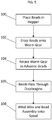
FIG. 5 , a method of manufacturing a linear thermal sensor is illustrated. Inblock 100, a plurality ofbeads 18 are placed in ahopper 24. Inblock 102, thebeads 18 are dropped onto aworm gear 26 and positioned between threads of theworm gear 26. Inblock 104, theworm gear 26 is rotated, thus advancing thebeads 18 along theworm gear 26 and onto awire 12. As thebeads 18 advance onto thewire 12, thebeads 18 pass through a plurality offlexible diaphragms 38 atblock 106. Theflexible diaphragms 38 are configured to position thewire 12 relative to thecentral bead openings 20 of thebeads 18, while allowing thebeads 18 to advance along theworm gear 26 and through the plurality ofdiaphragms 38. In some embodiments, inblock 108, thewire 12 andbead 18 assembly is then wound onto a spool. - The use of the
worm gear 26 and thediaphragms 38 as disclosed herein results in a manufacturing apparatus and process that is simple, cost effective, and reduces complexity of the sleeving operation of the plurality ofbeads 18 onto thewire 12. Further, such an apparatus and method significantly reduce the manual operation necessary to perform such an assembly. - The term "about" is intended to include the degree of error associated with measurement of the particular quantity based upon the equipment available at the time of filing the application.
- The terminology used herein is for the purpose of describing particular embodiments only and is not intended to be limiting of the present disclosure. As used herein, the singular forms "a", "an" and "the" are intended to include the plural forms as well, unless the context clearly indicates otherwise. It will be further understood that the terms "comprises" and/or "comprising," when used in this specification, specify the presence of stated features, integers, steps, operations, elements, and/or components, but do not preclude the presence or addition of one or more other features, integers, steps, operations, element components, and/or groups thereof.
- While the present disclosure has been described with reference to an exemplary embodiment or embodiments, it will be understood by those skilled in the art that various changes may be made and equivalents may be substituted for elements thereof without departing from the scope of the present disclosure. In addition, many modifications may be made to adapt a particular situation or material to the teachings of the present disclosure without departing from the essential scope thereof. Therefore, it is intended that the present disclosure not be limited to the particular embodiment disclosed as the best mode contemplated for carrying out this present disclosure, but that the present disclosure will include all embodiments falling within the scope of the claims.
Claims (15)
- A sleeving apparatus comprising:a worm gear, the worm gear having a plurality of threads, the worm gear receptive of a bead between adjacent threads of the plurality of threads; anda plurality of flexible diaphragms positioned along the worm gear, each diaphragm of the plurality of diaphragms configured to position a wire in alignment with a central bead opening of the bead;wherein with rotation of the worm gear about a worm gear axis the bead advances onto the wire with the wire passing into the central bead opening, the plurality of diaphragms configured to allow passage of the bead through each diaphragm of the plurality of diaphragms.
- The sleeving apparatus of claim 1, wherein each diaphragm of the plurality of diaphragms includes a central diaphragm opening configured to position the wire.
- The sleeving apparatus of claim 2, wherein each diaphragm of the plurality of diaphragms includes:a diaphragm rim defining an outer boundary of the diaphragm; anda plurality of flexible members extending inwardly from the diaphragm rim to the central diaphragm opening.
- The sleeving apparatus of claim 3, wherein adjacent flexible members are separated at least partially along their length from the diaphragm rim to the central diaphragm opening.
- The sleeving apparatus of claim 3 or 4, wherein the plurality of flexible members are configured to move independently; and/or
wherein the plurality of flexible members is a plurality of flaps. - The sleeving apparatus of claim 3, 4 or 5, wherein the plurality of flexible members vary in size and/or shape.
- The sleeving apparatus of any preceding claim, wherein the plurality of diaphragms are formed from an elastomeric material; and/or
wherein the plurality of diaphragms are circular. - A method of installing one or more beads onto a wire, comprising:positioning one or more beads between adjacent threads of a worm gear;positioning a wire along a length of the worm gear via a plurality of flexible diaphragms;rotating the worm gear about a worm gear axis thus advancing the one or more beads onto the wire;urging the one or more beads along the wire and through the plurality of diaphragms via rotation of the worm gear about the worm gear axis.
- The method of claim 8, further comprising supporting the wire via a central diaphragm opening in each diaphragm of the plurality of diaphragms, the wire therefore positioned relative to a central bead opening of the one or more beads.
- The method of claim 8 or 9, wherein the one or more beads are advanced onto the wire via the central bead opening.
- The method of claim 8, 9 or 10, further comprising urging the one or more beads through the plurality of diaphragms via a plurality of flexible members formed in each diaphragm of the plurality of diaphragms.
- The method of claim 11, wherein the plurality of flaps extend from a diaphragm rim to a central diaphragm opening, the plurality of flexible members separated at least partially along their length.
- The sleeving apparatus of any one of claims 1-7, further comprising a hopper disposed above the worm gear configured to feed the bead onto the worm gear; or
the method of any one of claims 8-12, further comprising dropping the one or more beads onto the worm gear from a hopper. - The system or method of any preceding claim, wherein the worm gear is configured such that a pitch between the adjacent threads is greater than a bead length of the bead.
- The sleeving apparatus of any one of claims 1-7 or 14, further comprising a spool to receive a sleeved wire; or
the method of any one of claims 8-14, further comprising winding the wire and the one or more beads onto a spool.
Applications Claiming Priority (1)
| Application Number | Priority Date | Filing Date | Title |
|---|---|---|---|
| US16/542,555 US11415467B2 (en) | 2019-08-16 | 2019-08-16 | Bead stringing apparatus for linear thermal sensors |
Publications (2)
| Publication Number | Publication Date |
|---|---|
| EP3779383A1 true EP3779383A1 (en) | 2021-02-17 |
| EP3779383B1 EP3779383B1 (en) | 2023-08-02 |
Family
ID=68762504
Family Applications (1)
| Application Number | Title | Priority Date | Filing Date |
|---|---|---|---|
| EP19212732.2A Active EP3779383B1 (en) | 2019-08-16 | 2019-11-29 | Bead stringing apparatus for linear thermal sensors |
Country Status (3)
| Country | Link |
|---|---|
| US (1) | US11415467B2 (en) |
| EP (1) | EP3779383B1 (en) |
| ES (1) | ES2953035T3 (en) |
Citations (4)
| Publication number | Priority date | Publication date | Assignee | Title |
|---|---|---|---|---|
| US2587916A (en) * | 1949-09-14 | 1952-03-04 | Specialties Dev Corp | Heat detecting cable |
| US4785521A (en) * | 1987-03-23 | 1988-11-22 | Ho Sheng Wu | Method for automatically linking beads or the like |
| DE102011012681A1 (en) * | 2011-03-01 | 2012-09-06 | Hella Kgaa Hueck & Co. | High-temperature sensor for arrangement in a metal tube, in particular within an exhaust line of an internal combustion engine |
| KR101747036B1 (en) * | 2016-06-20 | 2017-06-14 | 최종일 | String bead device |
Family Cites Families (13)
| Publication number | Priority date | Publication date | Assignee | Title |
|---|---|---|---|---|
| US244452A (en) | 1881-07-19 | halstenbach | ||
| US1866634A (en) | 1932-07-12 | eisler | ||
| US2641389A (en) * | 1948-02-28 | 1953-06-09 | Bagdon Richard | Bead threading machine |
| US2640631A (en) * | 1949-04-14 | 1953-06-02 | Virgy E Litterio | Mechanism for threading beads |
| US2885130A (en) * | 1956-02-15 | 1959-05-05 | Spool Max | Bead-stringing machines |
| US3133345A (en) * | 1959-11-09 | 1964-05-19 | Charles J Curtiss | Method of assembling a sinker to any part of a fishing line |
| US3004690A (en) | 1960-04-27 | 1961-10-17 | Spool Max | Bead-stringing machines |
| US3196064A (en) * | 1962-12-14 | 1965-07-20 | Tell Mfg Company Inc | Method and apparatus for the manufacture of beads |
| US3907180A (en) * | 1974-06-03 | 1975-09-23 | John R Birk | Bead orienting apparatus |
| JPS575038Y2 (en) * | 1979-01-26 | 1982-01-29 | ||
| US6455781B1 (en) | 2001-08-23 | 2002-09-24 | Chartered Semiconductor Manufacturing Ltd. | Thermocouple ceramic bead insulator |
| US7046116B2 (en) | 2002-11-12 | 2006-05-16 | Heraeus Sensor Technology Gmbh | Temperature probe and its use |
| US20060088079A1 (en) | 2004-09-29 | 2006-04-27 | Len Hom | Ceramic bead insulators and articulating thermocouple assemblies |
-
2019
- 2019-08-16 US US16/542,555 patent/US11415467B2/en active Active
- 2019-11-29 ES ES19212732T patent/ES2953035T3/en active Active
- 2019-11-29 EP EP19212732.2A patent/EP3779383B1/en active Active
Patent Citations (4)
| Publication number | Priority date | Publication date | Assignee | Title |
|---|---|---|---|---|
| US2587916A (en) * | 1949-09-14 | 1952-03-04 | Specialties Dev Corp | Heat detecting cable |
| US4785521A (en) * | 1987-03-23 | 1988-11-22 | Ho Sheng Wu | Method for automatically linking beads or the like |
| DE102011012681A1 (en) * | 2011-03-01 | 2012-09-06 | Hella Kgaa Hueck & Co. | High-temperature sensor for arrangement in a metal tube, in particular within an exhaust line of an internal combustion engine |
| KR101747036B1 (en) * | 2016-06-20 | 2017-06-14 | 최종일 | String bead device |
Also Published As
| Publication number | Publication date |
|---|---|
| ES2953035T3 (en) | 2023-11-07 |
| EP3779383B1 (en) | 2023-08-02 |
| US11415467B2 (en) | 2022-08-16 |
| US20210048349A1 (en) | 2021-02-18 |
Similar Documents
| Publication | Publication Date | Title |
|---|---|---|
| US4125423A (en) | Reinforced plastic tapered rod products and the method and apparatus for producing same | |
| CN106536390B (en) | Coil Manufacturing Apparatus and Method | |
| CN104002492B (en) | Self-adjustable silk thread prefabrication system | |
| JP2019033558A5 (en) | ||
| US20080010812A1 (en) | Method of forming single-layer coils | |
| JP2005531429A (en) | Apparatus and method for continuously producing reinforcement-reinforced hose-like structures | |
| EP1419850A2 (en) | Gasket singulation and insertion apparata and methods | |
| US11415467B2 (en) | Bead stringing apparatus for linear thermal sensors | |
| US2068675A (en) | Method of and apparatus for manufacturing screens | |
| CN102891005B (en) | Multi-wire winding method | |
| GB2048137A (en) | Apparatus and method of coiling a wire | |
| US5609463A (en) | Method of supplying parts and supplying device | |
| CN1822247B (en) | Tool, method and device for manufacturing an electrical harness | |
| US4549335A (en) | Method of manufacturing multiconductor cables | |
| TWI846173B (en) | Line array winding and deployment system | |
| SE420253B (en) | PROCEDURE AND APPARATUS FOR ASTAD COMMANDING OF A FIELD WINDING FOR AN ELECTROMAGNETIC MACHINE | |
| JP6777532B2 (en) | Wire winding jig and wire winding method using it | |
| KR102908353B1 (en) | Taping apparatus for attaching tape to columnar core body | |
| EP3706290A1 (en) | Method for winding of a concentrated coil for an electric machine | |
| CN1238467A (en) | Optical fiber ribbon stranding method and device | |
| FI81741C (en) | ANORDINATION FOR THE FRAMEWORK OF TRAILERS. | |
| FI72831C (en) | ANORDNING FOER ATT TVINNA AOTMINSTONE TVAO LEDARE. | |
| JP6965661B2 (en) | Cord spacing adjustment mechanism and ply material manufacturing equipment and ply material manufacturing method | |
| CN119069256A (en) | Device and method for winding thread-like material | |
| HK1234381B (en) | Coil making apparatus and method |
Legal Events
| Date | Code | Title | Description |
|---|---|---|---|
| PUAI | Public reference made under article 153(3) epc to a published international application that has entered the european phase |
Free format text: ORIGINAL CODE: 0009012 |
|
| STAA | Information on the status of an ep patent application or granted ep patent |
Free format text: STATUS: THE APPLICATION HAS BEEN PUBLISHED |
|
| AK | Designated contracting states |
Kind code of ref document: A1 Designated state(s): AL AT BE BG CH CY CZ DE DK EE ES FI FR GB GR HR HU IE IS IT LI LT LU LV MC MK MT NL NO PL PT RO RS SE SI SK SM TR |
|
| AX | Request for extension of the european patent |
Extension state: BA ME |
|
| STAA | Information on the status of an ep patent application or granted ep patent |
Free format text: STATUS: REQUEST FOR EXAMINATION WAS MADE |
|
| 17P | Request for examination filed |
Effective date: 20210816 |
|
| RBV | Designated contracting states (corrected) |
Designated state(s): AL AT BE BG CH CY CZ DE DK EE ES FI FR GB GR HR HU IE IS IT LI LT LU LV MC MK MT NL NO PL PT RO RS SE SI SK SM TR |
|
| RIN1 | Information on inventor provided before grant (corrected) |
Inventor name: GALWAY, DANIEL JAMES Inventor name: ROGERS, AARON STANLEY |
|
| GRAP | Despatch of communication of intention to grant a patent |
Free format text: ORIGINAL CODE: EPIDOSNIGR1 |
|
| STAA | Information on the status of an ep patent application or granted ep patent |
Free format text: STATUS: GRANT OF PATENT IS INTENDED |
|
| INTG | Intention to grant announced |
Effective date: 20230227 |
|
| GRAS | Grant fee paid |
Free format text: ORIGINAL CODE: EPIDOSNIGR3 |
|
| GRAA | (expected) grant |
Free format text: ORIGINAL CODE: 0009210 |
|
| STAA | Information on the status of an ep patent application or granted ep patent |
Free format text: STATUS: THE PATENT HAS BEEN GRANTED |
|
| P01 | Opt-out of the competence of the unified patent court (upc) registered |
Effective date: 20230603 |
|
| AK | Designated contracting states |
Kind code of ref document: B1 Designated state(s): AL AT BE BG CH CY CZ DE DK EE ES FI FR GB GR HR HU IE IS IT LI LT LU LV MC MK MT NL NO PL PT RO RS SE SI SK SM TR |
|
| REG | Reference to a national code |
Ref country code: GB Ref legal event code: FG4D |
|
| REG | Reference to a national code |
Ref country code: CH Ref legal event code: EP |
|
| REG | Reference to a national code |
Ref country code: DE Ref legal event code: R096 Ref document number: 602019033944 Country of ref document: DE |
|
| REG | Reference to a national code |
Ref country code: IE Ref legal event code: FG4D |
|
| REG | Reference to a national code |
Ref country code: LT Ref legal event code: MG9D |
|
| REG | Reference to a national code |
Ref country code: NL Ref legal event code: MP Effective date: 20230802 |
|
| REG | Reference to a national code |
Ref country code: AT Ref legal event code: MK05 Ref document number: 1595292 Country of ref document: AT Kind code of ref document: T Effective date: 20230802 |
|
| PG25 | Lapsed in a contracting state [announced via postgrant information from national office to epo] |
Ref country code: GR Free format text: LAPSE BECAUSE OF FAILURE TO SUBMIT A TRANSLATION OF THE DESCRIPTION OR TO PAY THE FEE WITHIN THE PRESCRIBED TIME-LIMIT Effective date: 20231103 |
|
| PG25 | Lapsed in a contracting state [announced via postgrant information from national office to epo] |
Ref country code: IS Free format text: LAPSE BECAUSE OF FAILURE TO SUBMIT A TRANSLATION OF THE DESCRIPTION OR TO PAY THE FEE WITHIN THE PRESCRIBED TIME-LIMIT Effective date: 20231202 |
|
| PG25 | Lapsed in a contracting state [announced via postgrant information from national office to epo] |
Ref country code: SE Free format text: LAPSE BECAUSE OF FAILURE TO SUBMIT A TRANSLATION OF THE DESCRIPTION OR TO PAY THE FEE WITHIN THE PRESCRIBED TIME-LIMIT Effective date: 20230802 Ref country code: RS Free format text: LAPSE BECAUSE OF FAILURE TO SUBMIT A TRANSLATION OF THE DESCRIPTION OR TO PAY THE FEE WITHIN THE PRESCRIBED TIME-LIMIT Effective date: 20230802 Ref country code: PT Free format text: LAPSE BECAUSE OF FAILURE TO SUBMIT A TRANSLATION OF THE DESCRIPTION OR TO PAY THE FEE WITHIN THE PRESCRIBED TIME-LIMIT Effective date: 20231204 Ref country code: NO Free format text: LAPSE BECAUSE OF FAILURE TO SUBMIT A TRANSLATION OF THE DESCRIPTION OR TO PAY THE FEE WITHIN THE PRESCRIBED TIME-LIMIT Effective date: 20231102 Ref country code: NL Free format text: LAPSE BECAUSE OF FAILURE TO SUBMIT A TRANSLATION OF THE DESCRIPTION OR TO PAY THE FEE WITHIN THE PRESCRIBED TIME-LIMIT Effective date: 20230802 Ref country code: LV Free format text: LAPSE BECAUSE OF FAILURE TO SUBMIT A TRANSLATION OF THE DESCRIPTION OR TO PAY THE FEE WITHIN THE PRESCRIBED TIME-LIMIT Effective date: 20230802 Ref country code: LT Free format text: LAPSE BECAUSE OF FAILURE TO SUBMIT A TRANSLATION OF THE DESCRIPTION OR TO PAY THE FEE WITHIN THE PRESCRIBED TIME-LIMIT Effective date: 20230802 Ref country code: IS Free format text: LAPSE BECAUSE OF FAILURE TO SUBMIT A TRANSLATION OF THE DESCRIPTION OR TO PAY THE FEE WITHIN THE PRESCRIBED TIME-LIMIT Effective date: 20231202 Ref country code: HR Free format text: LAPSE BECAUSE OF FAILURE TO SUBMIT A TRANSLATION OF THE DESCRIPTION OR TO PAY THE FEE WITHIN THE PRESCRIBED TIME-LIMIT Effective date: 20230802 Ref country code: GR Free format text: LAPSE BECAUSE OF FAILURE TO SUBMIT A TRANSLATION OF THE DESCRIPTION OR TO PAY THE FEE WITHIN THE PRESCRIBED TIME-LIMIT Effective date: 20231103 Ref country code: FI Free format text: LAPSE BECAUSE OF FAILURE TO SUBMIT A TRANSLATION OF THE DESCRIPTION OR TO PAY THE FEE WITHIN THE PRESCRIBED TIME-LIMIT Effective date: 20230802 Ref country code: AT Free format text: LAPSE BECAUSE OF FAILURE TO SUBMIT A TRANSLATION OF THE DESCRIPTION OR TO PAY THE FEE WITHIN THE PRESCRIBED TIME-LIMIT Effective date: 20230802 |
|
| PG25 | Lapsed in a contracting state [announced via postgrant information from national office to epo] |
Ref country code: PL Free format text: LAPSE BECAUSE OF FAILURE TO SUBMIT A TRANSLATION OF THE DESCRIPTION OR TO PAY THE FEE WITHIN THE PRESCRIBED TIME-LIMIT Effective date: 20230802 |
|
| PG25 | Lapsed in a contracting state [announced via postgrant information from national office to epo] |
Ref country code: SM Free format text: LAPSE BECAUSE OF FAILURE TO SUBMIT A TRANSLATION OF THE DESCRIPTION OR TO PAY THE FEE WITHIN THE PRESCRIBED TIME-LIMIT Effective date: 20230802 Ref country code: RO Free format text: LAPSE BECAUSE OF FAILURE TO SUBMIT A TRANSLATION OF THE DESCRIPTION OR TO PAY THE FEE WITHIN THE PRESCRIBED TIME-LIMIT Effective date: 20230802 Ref country code: EE Free format text: LAPSE BECAUSE OF FAILURE TO SUBMIT A TRANSLATION OF THE DESCRIPTION OR TO PAY THE FEE WITHIN THE PRESCRIBED TIME-LIMIT Effective date: 20230802 Ref country code: DK Free format text: LAPSE BECAUSE OF FAILURE TO SUBMIT A TRANSLATION OF THE DESCRIPTION OR TO PAY THE FEE WITHIN THE PRESCRIBED TIME-LIMIT Effective date: 20230802 Ref country code: CZ Free format text: LAPSE BECAUSE OF FAILURE TO SUBMIT A TRANSLATION OF THE DESCRIPTION OR TO PAY THE FEE WITHIN THE PRESCRIBED TIME-LIMIT Effective date: 20230802 Ref country code: SK Free format text: LAPSE BECAUSE OF FAILURE TO SUBMIT A TRANSLATION OF THE DESCRIPTION OR TO PAY THE FEE WITHIN THE PRESCRIBED TIME-LIMIT Effective date: 20230802 |
|
| REG | Reference to a national code |
Ref country code: DE Ref legal event code: R097 Ref document number: 602019033944 Country of ref document: DE |
|
| PLBE | No opposition filed within time limit |
Free format text: ORIGINAL CODE: 0009261 |
|
| STAA | Information on the status of an ep patent application or granted ep patent |
Free format text: STATUS: NO OPPOSITION FILED WITHIN TIME LIMIT |
|
| REG | Reference to a national code |
Ref country code: CH Ref legal event code: PL |
|
| PG25 | Lapsed in a contracting state [announced via postgrant information from national office to epo] |
Ref country code: MC Free format text: LAPSE BECAUSE OF FAILURE TO SUBMIT A TRANSLATION OF THE DESCRIPTION OR TO PAY THE FEE WITHIN THE PRESCRIBED TIME-LIMIT Effective date: 20230802 |
|
| 26N | No opposition filed |
Effective date: 20240503 |
|
| PG25 | Lapsed in a contracting state [announced via postgrant information from national office to epo] |
Ref country code: LU Free format text: LAPSE BECAUSE OF NON-PAYMENT OF DUE FEES Effective date: 20231129 |
|
| PG25 | Lapsed in a contracting state [announced via postgrant information from national office to epo] |
Ref country code: CH Free format text: LAPSE BECAUSE OF NON-PAYMENT OF DUE FEES Effective date: 20231130 |
|
| PG25 | Lapsed in a contracting state [announced via postgrant information from national office to epo] |
Ref country code: MC Free format text: LAPSE BECAUSE OF FAILURE TO SUBMIT A TRANSLATION OF THE DESCRIPTION OR TO PAY THE FEE WITHIN THE PRESCRIBED TIME-LIMIT Effective date: 20230802 Ref country code: LU Free format text: LAPSE BECAUSE OF NON-PAYMENT OF DUE FEES Effective date: 20231129 Ref country code: CH Free format text: LAPSE BECAUSE OF NON-PAYMENT OF DUE FEES Effective date: 20231130 Ref country code: SI Free format text: LAPSE BECAUSE OF FAILURE TO SUBMIT A TRANSLATION OF THE DESCRIPTION OR TO PAY THE FEE WITHIN THE PRESCRIBED TIME-LIMIT Effective date: 20230802 |
|
| REG | Reference to a national code |
Ref country code: BE Ref legal event code: MM Effective date: 20231130 |
|
| REG | Reference to a national code |
Ref country code: IE Ref legal event code: MM4A |
|
| PG25 | Lapsed in a contracting state [announced via postgrant information from national office to epo] |
Ref country code: IE Free format text: LAPSE BECAUSE OF NON-PAYMENT OF DUE FEES Effective date: 20231129 |
|
| PG25 | Lapsed in a contracting state [announced via postgrant information from national office to epo] |
Ref country code: BE Free format text: LAPSE BECAUSE OF NON-PAYMENT OF DUE FEES Effective date: 20231130 |
|
| PG25 | Lapsed in a contracting state [announced via postgrant information from national office to epo] |
Ref country code: IE Free format text: LAPSE BECAUSE OF NON-PAYMENT OF DUE FEES Effective date: 20231129 Ref country code: BE Free format text: LAPSE BECAUSE OF NON-PAYMENT OF DUE FEES Effective date: 20231130 |
|
| PG25 | Lapsed in a contracting state [announced via postgrant information from national office to epo] |
Ref country code: BG Free format text: LAPSE BECAUSE OF FAILURE TO SUBMIT A TRANSLATION OF THE DESCRIPTION OR TO PAY THE FEE WITHIN THE PRESCRIBED TIME-LIMIT Effective date: 20230802 |
|
| PG25 | Lapsed in a contracting state [announced via postgrant information from national office to epo] |
Ref country code: BG Free format text: LAPSE BECAUSE OF FAILURE TO SUBMIT A TRANSLATION OF THE DESCRIPTION OR TO PAY THE FEE WITHIN THE PRESCRIBED TIME-LIMIT Effective date: 20230802 |
|
| PG25 | Lapsed in a contracting state [announced via postgrant information from national office to epo] |
Ref country code: CY Free format text: LAPSE BECAUSE OF FAILURE TO SUBMIT A TRANSLATION OF THE DESCRIPTION OR TO PAY THE FEE WITHIN THE PRESCRIBED TIME-LIMIT; INVALID AB INITIO Effective date: 20191129 |
|
| PG25 | Lapsed in a contracting state [announced via postgrant information from national office to epo] |
Ref country code: HU Free format text: LAPSE BECAUSE OF FAILURE TO SUBMIT A TRANSLATION OF THE DESCRIPTION OR TO PAY THE FEE WITHIN THE PRESCRIBED TIME-LIMIT; INVALID AB INITIO Effective date: 20191129 |
|
| PG25 | Lapsed in a contracting state [announced via postgrant information from national office to epo] |
Ref country code: TR Free format text: LAPSE BECAUSE OF FAILURE TO SUBMIT A TRANSLATION OF THE DESCRIPTION OR TO PAY THE FEE WITHIN THE PRESCRIBED TIME-LIMIT Effective date: 20230802 |
|
| PGFP | Annual fee paid to national office [announced via postgrant information from national office to epo] |
Ref country code: DE Payment date: 20251022 Year of fee payment: 7 |
|
| PGFP | Annual fee paid to national office [announced via postgrant information from national office to epo] |
Ref country code: GB Payment date: 20251023 Year of fee payment: 7 |
|
| PGFP | Annual fee paid to national office [announced via postgrant information from national office to epo] |
Ref country code: IT Payment date: 20251022 Year of fee payment: 7 |
|
| PGFP | Annual fee paid to national office [announced via postgrant information from national office to epo] |
Ref country code: FR Payment date: 20251022 Year of fee payment: 7 |
|
| PGFP | Annual fee paid to national office [announced via postgrant information from national office to epo] |
Ref country code: ES Payment date: 20251201 Year of fee payment: 7 |