EP3779382A1 - Wireless energy-harvesting sensor probe - Google Patents
Wireless energy-harvesting sensor probe Download PDFInfo
- Publication number
- EP3779382A1 EP3779382A1 EP20191043.7A EP20191043A EP3779382A1 EP 3779382 A1 EP3779382 A1 EP 3779382A1 EP 20191043 A EP20191043 A EP 20191043A EP 3779382 A1 EP3779382 A1 EP 3779382A1
- Authority
- EP
- European Patent Office
- Prior art keywords
- sensor probe
- probe
- radio frequency
- recited
- antenna
- Prior art date
- Legal status (The legal status is an assumption and is not a legal conclusion. Google has not performed a legal analysis and makes no representation as to the accuracy of the status listed.)
- Granted
Links
Images


Classifications
-
- G—PHYSICS
- G06—COMPUTING OR CALCULATING; COUNTING
- G06K—GRAPHICAL DATA READING; PRESENTATION OF DATA; RECORD CARRIERS; HANDLING RECORD CARRIERS
- G06K17/00—Methods or arrangements for effecting co-operative working between equipments covered by two or more of main groups G06K1/00 - G06K15/00, e.g. automatic card files incorporating conveying and reading operations
- G06K17/0022—Methods or arrangements for effecting co-operative working between equipments covered by two or more of main groups G06K1/00 - G06K15/00, e.g. automatic card files incorporating conveying and reading operations arrangements or provisions for transferring data to distant stations, e.g. from a sensing device
- G06K17/0029—Methods or arrangements for effecting co-operative working between equipments covered by two or more of main groups G06K1/00 - G06K15/00, e.g. automatic card files incorporating conveying and reading operations arrangements or provisions for transferring data to distant stations, e.g. from a sensing device the arrangement being specially adapted for wireless interrogation of grouped or bundled articles tagged with wireless record carriers
-
- G—PHYSICS
- G01—MEASURING; TESTING
- G01K—MEASURING TEMPERATURE; MEASURING QUANTITY OF HEAT; THERMALLY-SENSITIVE ELEMENTS NOT OTHERWISE PROVIDED FOR
- G01K1/00—Details of thermometers not specially adapted for particular types of thermometer
- G01K1/02—Means for indicating or recording specially adapted for thermometers
- G01K1/024—Means for indicating or recording specially adapted for thermometers for remote indication
-
- G—PHYSICS
- G01—MEASURING; TESTING
- G01K—MEASURING TEMPERATURE; MEASURING QUANTITY OF HEAT; THERMALLY-SENSITIVE ELEMENTS NOT OTHERWISE PROVIDED FOR
- G01K13/00—Thermometers specially adapted for specific purposes
-
- G—PHYSICS
- G06—COMPUTING OR CALCULATING; COUNTING
- G06K—GRAPHICAL DATA READING; PRESENTATION OF DATA; RECORD CARRIERS; HANDLING RECORD CARRIERS
- G06K19/00—Record carriers for use with machines and with at least a part designed to carry digital markings
- G06K19/06—Record carriers for use with machines and with at least a part designed to carry digital markings characterised by the kind of the digital marking, e.g. shape, nature, code
- G06K19/067—Record carriers with conductive marks, printed circuits or semiconductor circuit elements, e.g. credit or identity cards also with resonating or responding marks without active components
- G06K19/07—Record carriers with conductive marks, printed circuits or semiconductor circuit elements, e.g. credit or identity cards also with resonating or responding marks without active components with integrated circuit chips
- G06K19/077—Constructional details, e.g. mounting of circuits in the carrier
- G06K19/07749—Constructional details, e.g. mounting of circuits in the carrier the record carrier being capable of non-contact communication, e.g. constructional details of the antenna of a non-contact smart card
- G06K19/07773—Antenna details
-
- H—ELECTRICITY
- H04—ELECTRIC COMMUNICATION TECHNIQUE
- H04W—WIRELESS COMMUNICATION NETWORKS
- H04W4/00—Services specially adapted for wireless communication networks; Facilities therefor
- H04W4/80—Services using short range communication, e.g. near-field communication [NFC], radio-frequency identification [RFID] or low energy communication
-
- G—PHYSICS
- G01—MEASURING; TESTING
- G01K—MEASURING TEMPERATURE; MEASURING QUANTITY OF HEAT; THERMALLY-SENSITIVE ELEMENTS NOT OTHERWISE PROVIDED FOR
- G01K2207/00—Application of thermometers in household appliances
- G01K2207/02—Application of thermometers in household appliances for measuring food temperature
- G01K2207/06—Application of thermometers in household appliances for measuring food temperature for preparation purposes
-
- G—PHYSICS
- G01—MEASURING; TESTING
- G01K—MEASURING TEMPERATURE; MEASURING QUANTITY OF HEAT; THERMALLY-SENSITIVE ELEMENTS NOT OTHERWISE PROVIDED FOR
- G01K2215/00—Details concerning sensor power supply
Definitions
- the present invention is directed to a wireless sensor probe for monitoring temperature.
- the invention is directed to a wireless energy-harvesting sensor probe for monitoring temperature in food.
- a wireless, battery-free meat probe eliminates the hassles of dealing with long wires and having to charge batteries, thereby improving usability and longevity of the product.
- few meat probes in the market satisfy all the criteria: wireless, battery-free, and able to communicate with the oven.
- Key challenges for wireless solutions are the large chip size for Bluetooth, which results in a large diameter of the spit(needle), and the need for a battery.
- Analog probes based on Surface Acoustic Wave (SAW) devices are either orientation-dependent or are expensive for even a single accurate temperature monitoring location. Customers prefer the ability to monitor temperature at different depths inside a piece of meat being cooked, or to have multiple probes inside.
- SAW Surface Acoustic Wave
- the solution is provided by a battery-free sensor probe for measuring the temperature of food, as defined in claim 1.
- the sensor probe includes a probe portion and a handle.
- the probe portion has a temperature sensor, a circuit board and a radio frequency identification device.
- the handle has an antenna connected to radio frequency identification device and the circuit board.
- the sensor probe harvests energy from a radio frequency transmitter positioned near the sensor probe.
- the solution is also provided by a system for measuring the temperature of food in an oven, as defined in claim 10.
- the system includes a battery-free sensor probe configured to be inserted into the food and a radio frequency transmitter positioned in the oven.
- the radio frequency transmitter sends a signal to the battery-free sensor probe to communicate with and power the battery-free sensor probe.
- the battery-free sensor probe of the system defined in any one of claims 10 to 15 may be the battery-free sensor probe that is defined in any one of the claims 1 to 9.
- An object of the invention is to provide a wireless energy-harvesting sensor probe or meat probe which can operate in a high temperature of operation inside an oven.
- a sensor probe 10 has a needle or probe portion 12 and a handle 14.
- the needle or probe portion 12 is configured to be inserted or partially inserted into a substance or material, such as, but not limited to meat.
- the handle 14 is configured to be positioned outside or partially of the substance or material.
- the probe portion 12 houses a circuit board 16 with a processor or microcontroller.
- the circuit board 16 includes a temperature sensor 18 and a near field communication (NFC)/ radio frequency identification (RFID) device 20.
- NFC near field communication
- RFID radio frequency identification
- the temperature sensor 18 and the NFC/RFID tag or device 20 may be separate components which are electrically connected to the circuit board 16; the circuit board 16 does not have a microcontroller; any combination of the circuit board 16, the temperature sensor 20, the NFC device 20, or other sensors may be housed in one component; and/or sensors in addition to, or other than, the temperature sensor may be provided, for example, but not limited to a humidity sensor.
- more than one temperature probe 18 may be provide at different locations along the length of the probe portion 12 to allow the temperature of the food to be measured at different locations.
- a terminal isolation device 22 is provided in the probe portion 12.
- the terminal isolation device 22 may be, but is not limited to, a capacitor or other type of thermal insulator.
- the handle 14 includes a housing 24 and a sensor probe antenna 26.
- the sensor probe antenna 26 may have a planar configuration as shown in FIGS. 1 and 2 .
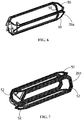
- the antenna may have other nonplanar configurations, such as, but not limited to: a curved antenna; an antenna 26a which has three planar members 50 which intersect to form a triangular cross-section as shown in FIGS. 6 ; or an antenna 26b which has four planar members 52 which intersect to form a square cross-section as shown in FIGS. 7 .
- Other configurations of the antenna with other numbers of planar members and other configurations may also be used.
- the sensor or meat probe 10 is positioned in the food or meat 30 in an oven 32.
- the oven has a radio frequency (RF) power transmitter 34 positioned proximate an oven cavity or compartment 36.
- RF radio frequency
- One of the key challenges for a sensor or meat probe 10 is the high temperature of operation inside an oven 32 or the like. Aside from using high-temperature-rated materials, the circuit board 16 and other electronics need to be protected from the high heat. Most semiconductor chips are only rated to operational temperatures of 85°C or 125°C. As the temperature in the oven compartment 36 is often in excess of 125°C, any electronics located in a reasonably-sized handle 14 cannot be practically retained under 125°C for 3 hours. As the best insulator inside the oven 32 is the food 30 itself, the circuit board 16 and other electronics is positioned in the needle or probe portion 12 when in use, thereby protecting or insulating the needle or probe portion 12 by the food 30.
- the probe 10 In order to use the probe 10, the probe 10 requires energy for operation. As the probe 10 does not contain batteries, the probe 10 must use energy harvesting for operation. The battery-free meat probe 10 requires a mechanism to harvest enough energy to power the circuit board 16, temperature sensor 18 and the NFC/RFID device 20. The NFC/RFID device 20 has a unique electronic identification which is distinguishable from other similar devices.
- Radio Frequency (RF) energy harvesting is using a dedicated RF power transmitter 34 in the oven 32 is used.
- the energy in the wireless signal sent from the power transmitter 34 to the probe 10 is re-purposed, to allow the probe 10 to operate and respond.
- An illustrative embodiment of the RF power transmitter 34 is a RFID device which utilizes energy from the reading device (in this case the oven 32) to operate and communicate back to the probe 10 (as indicated by arrow 38).
- the NFC chip or device 20, shown in diagrammatically in FIG. 3 is one example of an RFID device.
- the NFC system consists of a reader, which in the illustrative embodiment is the oven 32.
- the reader or oven 32 is a fixed system, without size restrictions, and is powered by AC current or one or more large batteries.
- the reader 32 consists of one or more reader electronic boards 33 connected (electrically and mechanically) to one or more reader antennas 35.
- the tags or devices 20 are smaller, portable, and battery-free systems which include a semiconductor NFC chip which is attached to the antenna 26.
- the NFC system supports communication range of up to approximately one meter using high-power readers.
- the NFC reader or oven 32 can detect multiple tags or devices 20 in the vicinity which is beneficial for large ovens where many pieces of food are cooked simultaneously. Alternatively, as shown in FIG.
- the oven rack 40 may be used as the reader antenna, thereby allowing for close proximity of the sensor probe 10 to the reader antenna or rack 40 regardless of the position of the meat 30 in the oven cavity or compartment 36.
- the oven rack 40 may be positioned in the oven 32 with or without electrical isolation.
- the rack 40 may act as a signal enhancer to facilitate communication with a radiator or reader antenna located at another location.
- the reader electronics 33 and/or the antenna 35 may be positioned in one, two, three, four or five walls of the oven cavity or compartment 36 and/or on the door of the oven and/or at any arbitrary position inside the cavity or compartment 36.
- the reader electronics 33 and reader antennas 35 may be configurable to radiate in various patterns.
- the meat probe system schematic is shown in FIGS. 2 and 3 .
- the handle 14 of the meat probe 10 contains the antenna 26, which connects to the NFC device 20.
- the NFC device 20 is a dynamic NFC tag chip that provides an energy-harvested output in addition to the decoded NFC data.
- the NFC device 20 contains a wafer-level chip-scale package (WLCSP) version of ST25DV.
- WLCSP wafer-level chip-scale package
- This NFC chip powers and communicates with, the circuit board 16 which includes, for example, an STM32 microcontroller from STMicroelectronics which uses Inter-Integrated Circuit (I2C) digital protocol, although other protocols may be used.
- I2C Inter-Integrated Circuit
- the STM32 is an ultra-low power 32-bit microcontroller in WLCSP form-factor. As the microcontroller is powered, the microcontroller communicates with the digital temperature sensor 14 using Serial Peripheral Interface (SPI) protocol, and updates the information to the NFC device 20, which in-turn relays the data back to the oven 32.
- SPI Serial Peripheral Interface
- Other NFC devices 20 may be used without departing from the scope of the invention.
- the configuration and the components of the circuit board 16 limited the level of miniaturization of the circuit board 16. While the invention is not so limited, in one illustrative example, the NFC device 20 and all active chips on the circuit board 16, such as, the microcontroller and the voltage regulator, were chosen in the smallest available form-factor - WLCSP package-type.
- the WLCSPs are devoid of low-temperature organic materials often used in other package types. However, other types, sizes and configurations of chips may be used.
- the circuit board 16 has a width of approximately 2.6mm and length of approximately 20mm.
- the smallest trace width and space used for routing is 100 ⁇ m, and only two metal layers were used for routing all the components on the circuit board 16.
- the choice of trace width and number of layers is governed by two factors: ensuring routability of all the components and minimizing manufacturing cost of the circuit board 16.
- other circuit boards 16 with other dimensions and other configurations may be used.
- the circuit board is fabricated from high-temperature circuit board material with a glass transition temperature of greater than 280°C and thermal degradation temperature of 390°C, such as Rogers 4350.
- the outside housing of the probe portion 12 is made from stain-less steel or other material which conducts heat.
- the handle material is Polytetrafluoroethylene (PTFE).
- the antenna is plain enameled copper wire wound on the PTFE handle, to achieve the target inductance of 4.8 ⁇ H at 13.56 MHz.
- other inductance, other frequency and other materials can be used without departing from the scope of the invention.
- circuit board 16 All the materials that are outside the food during operation are chosen to withstand 300°C.
- circuit board 16 and other electronics the electronics have a maximum recommended operational temperature of 85°C, as the electronics will not be subject to more than 74°C (165°F) during normal operation.
- a high-temperature material for the circuit board 16 allows the circuit board 16 to survive accidental exposures to 300°C.
- the antenna 26 is essentially an inductor tuned to operate at 13.56 MHz. As the stainless-steel probe portion 12 is small and blocks RF signals, the antenna 26 must be housed in the handle 14, and be capable of surviving 300°C. In one illustrative embodiment, the antenna 26 has a dimension of approximately 60mm x 16mm. However, other sizes and configurations of the antennas may be used. The dimensions and configurations of the antenna 26 are optimized to allow the probe 10 to be positioned in the oven compartment 36 at any orientation, allowing proper communication with the oven 32 or rack 40, whichever is used as the reader antenna.
- the antenna 26 is made from metal or other conductive material and is exposed to high temperatures in the oven compartment 36.
- the circuit board 16 is not rated to be operated at high temperatures for long periods of time. Consequently, in order to prevent heat from being conducted through the antenna 26 to the circuit board 16, the thermal isolation device 22 is provided in line with the antenna 26 proximate the circuit board 16. The thermal isolation device 22 is provided to dissipate the heat collected and transmitted by the antenna 26, thereby preventing harmful heat from reaching the circuit board 16. The thermal isolation device 22 does not adversely affect the electrical communication between the antenna 26 and the circuit board 16.
- the embodiments shown and described herein are directed to a sensor probe which is wireless and which does not need batteries, thereby allowing the needle of the sensor probe to have a small diameter.
- the life of the probe is not limited by battery life and safety concerns of placing batteries in an oven proximate food are eliminated.
- the probe is a low-cost NFC-based wireless battery-free solution for use with smart ovens.
- the wireless communication of the probe with the oven allows the oven temperature to be regulated based on the actual internal food temperature readings from the probe and not the oven ambient temperature.
Landscapes
- Engineering & Computer Science (AREA)
- Physics & Mathematics (AREA)
- General Physics & Mathematics (AREA)
- Computer Networks & Wireless Communication (AREA)
- Theoretical Computer Science (AREA)
- Computer Hardware Design (AREA)
- Microelectronics & Electronic Packaging (AREA)
- Signal Processing (AREA)
- General Engineering & Computer Science (AREA)
- Measuring Temperature Or Quantity Of Heat (AREA)
- Arrangements For Transmission Of Measured Signals (AREA)
Abstract
Description
- The present invention is directed to a wireless sensor probe for monitoring temperature. In particular, the invention is directed to a wireless energy-harvesting sensor probe for monitoring temperature in food.
- Proper handling and cooking of food, especially meats, is essential to avoiding contamination by disease-causing bacteria or pathogens. The United States Centers for Disease Control and prevention (CDC) estimates that every year 48 million people get sick from a foodborne illness, 128,000 are hospitalized, and 3,000 die . The US Food and Drug Administration (USFDA) recommends using a thermometer to ensure that a minimum temperature of 140°F to 165°F is attained inside the meat during cooking. Smart ovens communicate with temperature probes to enable energy-efficient regulation of temperature and prevent any risk of fire due to unattended overheating of food.
- A wireless, battery-free meat probe eliminates the hassles of dealing with long wires and having to charge batteries, thereby improving usability and longevity of the product. However, few meat probes in the market satisfy all the criteria: wireless, battery-free, and able to communicate with the oven. Key challenges for wireless solutions are the large chip size for Bluetooth, which results in a large diameter of the spit(needle), and the need for a battery. Analog probes based on Surface Acoustic Wave (SAW) devices are either orientation-dependent or are expensive for even a single accurate temperature monitoring location. Customers prefer the ability to monitor temperature at different depths inside a piece of meat being cooked, or to have multiple probes inside.
- It would be, therefore, be beneficial to provide a sensor probe which is wireless and which does not need batteries, thereby allowing the needle of the sensor probe to have a small diameter. In would also be beneficial to provide a sensor probe which could monitor the temperature of food at different depths.
- The solution is provided by a battery-free sensor probe for measuring the temperature of food, as defined in claim 1. The sensor probe includes a probe portion and a handle. The probe portion has a temperature sensor, a circuit board and a radio frequency identification device. The handle has an antenna connected to radio frequency identification device and the circuit board. The sensor probe harvests energy from a radio frequency transmitter positioned near the sensor probe.
- The solution is also provided by a system for measuring the temperature of food in an oven, as defined in
claim 10. The system includes a battery-free sensor probe configured to be inserted into the food and a radio frequency transmitter positioned in the oven. The radio frequency transmitter sends a signal to the battery-free sensor probe to communicate with and power the battery-free sensor probe. The battery-free sensor probe of the system defined in any one ofclaims 10 to 15 may be the battery-free sensor probe that is defined in any one of the claims 1 to 9. - The invention will now be described by way of example with reference to the accompanying drawings in which:.
-
FIG. 1 is a perspective view of an illustrative sensor probe of the present invention. -
FIG. 2 is a cross-sectional view of the sensor probe ofFIG. 1 taken along line 2-2. -
FIG. 3 is a diagrammatic view of the sensor probe ofFIG. 1 . -
FIG. 4 is a diagrammatic view of the sensor probe positioned in a food item which is positioned in an oven. -
FIG. 5 is a diagrammatic view of the sensor probe positioned in a food item which is positioned in an alternate oven. -
FIG. 6 is a perspective view of a first alternate antenna which can be used with the sensor probe of the present invention. -
FIG. 7 is a perspective view of a second alternate antenna which can be used with the sensor probe of the present invention. - The description of illustrative embodiments according to principles of the present invention is intended to be read in connection with the accompanying drawings, which are to be considered part of the entire written description. In the description of embodiments of the invention disclosed herein, any reference to direction or orientation is merely intended for convenience of description and is not intended in any way to limit the scope of the present invention. Relative terms such as "lower," "upper," "horizontal," "vertical," "above," "below," "up," "down," "top" and "bottom" as well as derivative thereof (e.g., "horizontally," "downwardly," "upwardly," etc.) should be construed to refer to the orientation as then described or as shown in the drawing under discussion. These relative terms are for convenience of description only and do not require that the apparatus be constructed or operated in a particular orientation unless explicitly indicated as such. Terms such as "attached," "affixed," "connected," "coupled," "interconnected," and similar refer to a relationship wherein structures are secured or attached to one another either directly or indirectly through intervening structures, as well as both movable or rigid attachments or relationships, unless expressly described otherwise.
- An object of the invention is to provide a wireless energy-harvesting sensor probe or meat probe which can operate in a high temperature of operation inside an oven.
- As shown in
FIGS. 1 and 2 , asensor probe 10 has a needle orprobe portion 12 and ahandle 14. The needle orprobe portion 12 is configured to be inserted or partially inserted into a substance or material, such as, but not limited to meat. Thehandle 14 is configured to be positioned outside or partially of the substance or material. - The
probe portion 12 houses acircuit board 16 with a processor or microcontroller. In the illustrative embodiment shown, thecircuit board 16 includes atemperature sensor 18 and a near field communication (NFC)/ radio frequency identification (RFID)device 20. However, in other illustrative embodiments: thetemperature sensor 18 and the NFC/RFID tag ordevice 20 may be separate components which are electrically connected to thecircuit board 16; thecircuit board 16 does not have a microcontroller; any combination of thecircuit board 16, thetemperature sensor 20, theNFC device 20, or other sensors may be housed in one component; and/or sensors in addition to, or other than, the temperature sensor may be provided, for example, but not limited to a humidity sensor. In alternate embodiments, more than onetemperature probe 18 may be provide at different locations along the length of theprobe portion 12 to allow the temperature of the food to be measured at different locations. - In the illustrative embodiment shown, a
terminal isolation device 22 is provided in theprobe portion 12. Theterminal isolation device 22 may be, but is not limited to, a capacitor or other type of thermal insulator. - The
handle 14 includes ahousing 24 and asensor probe antenna 26. Thesensor probe antenna 26 may have a planar configuration as shown inFIGS. 1 and 2 . Alternatively, the antenna may have other nonplanar configurations, such as, but not limited to: a curved antenna; anantenna 26a which has threeplanar members 50 which intersect to form a triangular cross-section as shown inFIGS. 6 ; or anantenna 26b which has fourplanar members 52 which intersect to form a square cross-section as shown inFIGS. 7 . Other configurations of the antenna with other numbers of planar members and other configurations may also be used. - As shown in
FIG. 4 , in operation, the sensor ormeat probe 10 is positioned in the food ormeat 30 in anoven 32. The oven has a radio frequency (RF)power transmitter 34 positioned proximate an oven cavity orcompartment 36. - One of the key challenges for a sensor or
meat probe 10 is the high temperature of operation inside anoven 32 or the like. Aside from using high-temperature-rated materials, thecircuit board 16 and other electronics need to be protected from the high heat. Most semiconductor chips are only rated to operational temperatures of 85°C or 125°C. As the temperature in theoven compartment 36 is often in excess of 125°C, any electronics located in a reasonably-sizedhandle 14 cannot be practically retained under 125°C for 3 hours. As the best insulator inside theoven 32 is thefood 30 itself, thecircuit board 16 and other electronics is positioned in the needle orprobe portion 12 when in use, thereby protecting or insulating the needle orprobe portion 12 by thefood 30. - In order to use the
probe 10, theprobe 10 requires energy for operation. As theprobe 10 does not contain batteries, theprobe 10 must use energy harvesting for operation. The battery-free meat probe 10 requires a mechanism to harvest enough energy to power thecircuit board 16,temperature sensor 18 and the NFC/RFID device 20. The NFC/RFID device 20 has a unique electronic identification which is distinguishable from other similar devices. - While an obvious source of energy inside an
oven compartment 36 is the heat, theprobe 10 must be operational even when the oven is just beginning to warm-up. In this phase, there is not enough temperature gradient to harvest the required power required for the electronics. Consequently, as shown inFIGS. 4 and 5 , Radio Frequency (RF) energy harvesting is using a dedicatedRF power transmitter 34 in theoven 32 is used. As the communication between theprobe 10 and thepower transmitter 34 is wireless, the energy in the wireless signal sent from thepower transmitter 34 to theprobe 10 is re-purposed, to allow theprobe 10 to operate and respond. An illustrative embodiment of theRF power transmitter 34 is a RFID device which utilizes energy from the reading device (in this case the oven 32) to operate and communicate back to the probe 10 (as indicated by arrow 38). The NFC chip ordevice 20, shown in diagrammatically inFIG. 3 , is one example of an RFID device. - The NFC system consists of a reader, which in the illustrative embodiment is the
oven 32. The reader oroven 32 is a fixed system, without size restrictions, and is powered by AC current or one or more large batteries. Thereader 32 consists of one or more readerelectronic boards 33 connected (electrically and mechanically) to one ormore reader antennas 35. The tags ordevices 20 are smaller, portable, and battery-free systems which include a semiconductor NFC chip which is attached to theantenna 26. The NFC system supports communication range of up to approximately one meter using high-power readers. The NFC reader oroven 32 can detect multiple tags ordevices 20 in the vicinity which is beneficial for large ovens where many pieces of food are cooked simultaneously. Alternatively, as shown inFIG. 5 , theoven rack 40 may be used as the reader antenna, thereby allowing for close proximity of thesensor probe 10 to the reader antenna orrack 40 regardless of the position of themeat 30 in the oven cavity orcompartment 36. Theoven rack 40 may be positioned in theoven 32 with or without electrical isolation. In another alternate embodiment, therack 40 may act as a signal enhancer to facilitate communication with a radiator or reader antenna located at another location. In other alternate embodiments, thereader electronics 33 and/or theantenna 35 may be positioned in one, two, three, four or five walls of the oven cavity orcompartment 36 and/or on the door of the oven and/or at any arbitrary position inside the cavity orcompartment 36. Thereader electronics 33 andreader antennas 35 may be configurable to radiate in various patterns. - The meat probe system schematic is shown in
FIGS. 2 and3 . Thehandle 14 of themeat probe 10 contains theantenna 26, which connects to theNFC device 20. In the illustrative embodiment, theNFC device 20 is a dynamic NFC tag chip that provides an energy-harvested output in addition to the decoded NFC data. One example of such theNFC device 20 contains a wafer-level chip-scale package (WLCSP) version of ST25DV. This NFC chip powers and communicates with, thecircuit board 16 which includes, for example, an STM32 microcontroller from STMicroelectronics which uses Inter-Integrated Circuit (I2C) digital protocol, although other protocols may be used. The STM32 is an ultra-low power 32-bit microcontroller in WLCSP form-factor. As the microcontroller is powered, the microcontroller communicates with thedigital temperature sensor 14 using Serial Peripheral Interface (SPI) protocol, and updates the information to theNFC device 20, which in-turn relays the data back to theoven 32.Other NFC devices 20 may be used without departing from the scope of the invention. - As it is desired to have the diameter of the
probe portion 12 to be equal to or less than 4 mm, the configuration and the components of thecircuit board 16 limited the level of miniaturization of thecircuit board 16. While the invention is not so limited, in one illustrative example, theNFC device 20 and all active chips on thecircuit board 16, such as, the microcontroller and the voltage regulator, were chosen in the smallest available form-factor - WLCSP package-type. The WLCSPs are devoid of low-temperature organic materials often used in other package types. However, other types, sizes and configurations of chips may be used. - In the illustrative embodiment shown, the
circuit board 16 has a width of approximately 2.6mm and length of approximately 20mm. The smallest trace width and space used for routing is 100µm, and only two metal layers were used for routing all the components on thecircuit board 16. The choice of trace width and number of layers is governed by two factors: ensuring routability of all the components and minimizing manufacturing cost of thecircuit board 16. However,other circuit boards 16 with other dimensions and other configurations may be used. - In the illustrative embodiment shown, the circuit board is fabricated from high-temperature circuit board material with a glass transition temperature of greater than 280°C and thermal degradation temperature of 390°C, such as Rogers 4350. The outside housing of the
probe portion 12 is made from stain-less steel or other material which conducts heat. The handle material is Polytetrafluoroethylene (PTFE). The antenna is plain enameled copper wire wound on the PTFE handle, to achieve the target inductance of 4.8µH at 13.56 MHz. However, other inductance, other frequency and other materials can be used without departing from the scope of the invention. - All the materials that are outside the food during operation are chosen to withstand 300°C. In contrast, the
circuit board 16 and other electronics the electronics have a maximum recommended operational temperature of 85°C, as the electronics will not be subject to more than 74°C (165°F) during normal operation. However, the use of a high-temperature material for thecircuit board 16 allows thecircuit board 16 to survive accidental exposures to 300°C. - The NFC communication described above employs near-field magnetic coupling. Therefore, the
antenna 26 is essentially an inductor tuned to operate at 13.56 MHz. As the stainless-steel probe portion 12 is small and blocks RF signals, theantenna 26 must be housed in thehandle 14, and be capable of surviving 300°C. In one illustrative embodiment, theantenna 26 has a dimension of approximately 60mm x 16mm. However, other sizes and configurations of the antennas may be used. The dimensions and configurations of theantenna 26 are optimized to allow theprobe 10 to be positioned in theoven compartment 36 at any orientation, allowing proper communication with theoven 32 orrack 40, whichever is used as the reader antenna. - The
antenna 26 is made from metal or other conductive material and is exposed to high temperatures in theoven compartment 36. In contrast, thecircuit board 16 is not rated to be operated at high temperatures for long periods of time. Consequently, in order to prevent heat from being conducted through theantenna 26 to thecircuit board 16, thethermal isolation device 22 is provided in line with theantenna 26 proximate thecircuit board 16. Thethermal isolation device 22 is provided to dissipate the heat collected and transmitted by theantenna 26, thereby preventing harmful heat from reaching thecircuit board 16. Thethermal isolation device 22 does not adversely affect the electrical communication between theantenna 26 and thecircuit board 16. - The embodiments shown and described herein are directed to a sensor probe which is wireless and which does not need batteries, thereby allowing the needle of the sensor probe to have a small diameter. In addition, as no batteries are required, the life of the probe is not limited by battery life and safety concerns of placing batteries in an oven proximate food are eliminated. The probe is a low-cost NFC-based wireless battery-free solution for use with smart ovens.
- The wireless communication of the probe with the oven allows the oven temperature to be regulated based on the actual internal food temperature readings from the probe and not the oven ambient temperature.
Claims (15)
- A battery-free sensor probe (10) for measuring the temperature of food (30), the sensor probe (10) comprising:a probe portion (12) having a temperature sensor (18), a circuit board (16) and a radio frequency identification device (20);a handle (14) having an antenna (26) connected to radio frequency identification device (20) and the circuit board (16);wherein the sensor probe (10) harvests energy from a radio frequency transmitter (34) positioned near the sensor probe (10).
- The sensor probe (10) as recited in claim 1, wherein the radio frequency identification device (20) is a near field communication device.
- The sensor probe (10) as recited in claim 1 or 2, wherein the antenna (26) is a planar device.
- The sensor probe (10) as recited in claim 1 or 2, wherein the antenna (26) has three planar members (50) which intersect to form a triangular cross-section.
- The sensor probe (10) as recited in claim 1 or 2, wherein the antenna (26) has four planar members (52) which intersect to form a square cross-section.
- The sensor probe (10) as recited in any preceding claim, wherein the temperature sensor (18) and the radio frequency identification device (20) are located on the printed circuit board (16).
- The sensor probe (10) as recited in any preceding claim, wherein a thermal isolation device (22) is provided to thermally insulate the circuit board (16) from the antenna (26).
- The sensor probe (10) as recited in claim 7, wherein the thermal isolation device (22) is a capacitor.
- The sensor probe (10) as recited in any preceding claim, wherein a diameter of the probe portion (12) is equal to or less than 4 mm.
- A system for measuring the temperature of food (30) in an oven (32), the system comprising:a battery-free sensor probe (10) configured to be inserted into the food (30);a radio frequency transmitter (34) positioned in the oven;wherein the radio frequency transmitter (34) sends a signal to the battery-free sensor probe (10) to communicate with and power the battery-free sensor probe (10).
- The system as recited in claim 10, wherein the radio frequency transmitter (34) has a reader which is positioned in a wall of the oven (32).
- The system as recited in claim 10, wherein the radio frequency transmitter (34) has a reader which is positioned in an oven rack (40) positioned in the oven (32).
- The system as recited in any one of claims 10 to 12, wherein the sensor probe (10) has a handle (14) having an antenna (26) which communicates with the radio frequency transmitter (34).
- The system as recited in claim 13, wherein the sensor probe (10) has a probe portion (12) having a temperature sensor (18), a circuit board (16) and a radio frequency identification device (20), the antenna (26) is connected to radio frequency identification device (20) and the circuit board (16).
- The sensor probe (10) as recited in claim 13 or 14, wherein the radio frequency transmitter (34) and the radio frequency identification device (20) are near field communication devices.
Applications Claiming Priority (2)
| Application Number | Priority Date | Filing Date | Title |
|---|---|---|---|
| US201962887012P | 2019-08-15 | 2019-08-15 | |
| US16/943,411 US11579019B2 (en) | 2019-08-15 | 2020-07-30 | Wireless energy-harvesting sensor probe |
Publications (2)
| Publication Number | Publication Date |
|---|---|
| EP3779382A1 true EP3779382A1 (en) | 2021-02-17 |
| EP3779382B1 EP3779382B1 (en) | 2024-07-03 |
Family
ID=72087905
Family Applications (1)
| Application Number | Title | Priority Date | Filing Date |
|---|---|---|---|
| EP20191043.7A Active EP3779382B1 (en) | 2019-08-15 | 2020-08-14 | Wireless energy-harvesting sensor probe |
Country Status (3)
| Country | Link |
|---|---|
| US (1) | US11579019B2 (en) |
| EP (1) | EP3779382B1 (en) |
| CN (1) | CN112465080B (en) |
Cited By (1)
| Publication number | Priority date | Publication date | Assignee | Title |
|---|---|---|---|---|
| EP4063810A1 (en) * | 2021-03-22 | 2022-09-28 | Tyco Electronics (Shanghai) Co., Ltd. | Wireless energy-harvesting sensor probe utilizing beam steering for in-oven power stealing |
Families Citing this family (7)
| Publication number | Priority date | Publication date | Assignee | Title |
|---|---|---|---|---|
| CN113267268A (en) * | 2021-05-27 | 2021-08-17 | 深圳市弘康国际电子科技有限公司 | Wireless detection barbecue thermometer |
| PL4119911T3 (en) * | 2021-07-16 | 2024-09-23 | Vorwerk & Co. Interholding Gmbh | Single stem thermometer |
| EP4163610A1 (en) | 2021-10-05 | 2023-04-12 | Versuni Holding B.V. | Temperature sensing probe and system |
| US12235164B2 (en) * | 2022-04-06 | 2025-02-25 | Antonio Mure | Temperature monitoring assembly |
| WO2024187782A1 (en) * | 2023-03-16 | 2024-09-19 | 珠海美佳音科技有限公司 | Food thermometer, repeater, and food thermometer assembly |
| WO2025130128A1 (en) * | 2023-12-20 | 2025-06-26 | 深圳市千分一智能技术有限公司 | Roast meat temperature probe |
| USD1101580S1 (en) | 2024-01-31 | 2025-11-11 | Sharkninja Operating Llc | Temperature probe holder |
Citations (3)
| Publication number | Priority date | Publication date | Assignee | Title |
|---|---|---|---|---|
| DE102004047758A1 (en) * | 2004-09-30 | 2006-04-06 | BSH Bosch und Siemens Hausgeräte GmbH | Temperature sensor device |
| US20090188396A1 (en) * | 2007-08-06 | 2009-07-30 | Hofmann Matthias C | Oven with wireless temperature sensor for use in monitoring food temperature |
| US20190041271A1 (en) * | 2017-08-07 | 2019-02-07 | Philip Preston | Method And Assembly For A Wireless Probe And Interrogator |
Family Cites Families (10)
| Publication number | Priority date | Publication date | Assignee | Title |
|---|---|---|---|---|
| IN188696B (en) * | 1998-05-18 | 2002-10-26 | Medisim Ltd | |
| US6568848B1 (en) * | 1999-09-20 | 2003-05-27 | Maverick Industries, Inc. | Wireless remote cooking thermometer system |
| ITMO20040193A1 (en) * | 2004-07-23 | 2004-10-23 | Angelo Grandi Cucine Spa | SYSTEM AND PROBE FOR REVALING A PARAMETER |
| US8013608B2 (en) * | 2009-06-19 | 2011-09-06 | Jeol Resonance Inc. | High-resolution NMR probe |
| US20160084986A1 (en) * | 2014-09-19 | 2016-03-24 | Pentair Thermal Management Llc | Snow and Ice Melting System and Sensors Therefor |
| CN106765361A (en) * | 2017-03-27 | 2017-05-31 | 徐士刚 | A kind of intelligent electromagnetic oven |
| WO2018213345A1 (en) * | 2017-05-15 | 2018-11-22 | Integrated Device Technology, Inc. | Wireless powered sensor and sensor systems |
| US11422037B2 (en) * | 2018-03-15 | 2022-08-23 | Brava Home, Inc. | Temperature probe systems and methods |
| WO2019212617A2 (en) * | 2018-05-03 | 2019-11-07 | Matrix Product Development, Inc. | Wireless temperature-measurement system |
| US20200182703A1 (en) * | 2018-12-11 | 2020-06-11 | Gina Marie Bourret | Methods, Devices, and Systems for Monitoring Temperatures |
-
2020
- 2020-07-30 US US16/943,411 patent/US11579019B2/en active Active
- 2020-08-14 EP EP20191043.7A patent/EP3779382B1/en active Active
- 2020-08-17 CN CN202010824229.2A patent/CN112465080B/en active Active
Patent Citations (3)
| Publication number | Priority date | Publication date | Assignee | Title |
|---|---|---|---|---|
| DE102004047758A1 (en) * | 2004-09-30 | 2006-04-06 | BSH Bosch und Siemens Hausgeräte GmbH | Temperature sensor device |
| US20090188396A1 (en) * | 2007-08-06 | 2009-07-30 | Hofmann Matthias C | Oven with wireless temperature sensor for use in monitoring food temperature |
| US20190041271A1 (en) * | 2017-08-07 | 2019-02-07 | Philip Preston | Method And Assembly For A Wireless Probe And Interrogator |
Cited By (3)
| Publication number | Priority date | Publication date | Assignee | Title |
|---|---|---|---|---|
| EP4063810A1 (en) * | 2021-03-22 | 2022-09-28 | Tyco Electronics (Shanghai) Co., Ltd. | Wireless energy-harvesting sensor probe utilizing beam steering for in-oven power stealing |
| CN115189487A (en) * | 2021-03-22 | 2022-10-14 | 泰科电子连接荷兰公司 | Wireless energy collection sensor probe for power stealing in oven by utilizing beam control |
| US12399065B2 (en) | 2021-03-22 | 2025-08-26 | Tyco Electronics (Shanghai) Co., Ltd. | Wireless energy-harvesting sensor probe utilizing beam steering for in-oven power stealing |
Also Published As
| Publication number | Publication date |
|---|---|
| CN112465080B (en) | 2024-07-05 |
| CN112465080A (en) | 2021-03-09 |
| US20210048347A1 (en) | 2021-02-18 |
| US11579019B2 (en) | 2023-02-14 |
| EP3779382B1 (en) | 2024-07-03 |
Similar Documents
| Publication | Publication Date | Title |
|---|---|---|
| EP3779382B1 (en) | Wireless energy-harvesting sensor probe | |
| US12571688B2 (en) | Wireless multi-point food thermometer | |
| US10801897B2 (en) | Thermometer and temperature monitoring system | |
| US10670470B2 (en) | Food thermometer and method of using thereof | |
| EP3788332B1 (en) | Wireless temperature-measurement system | |
| US11506545B2 (en) | Food thermometer and method of using thereof | |
| EP3281494B1 (en) | A microwave powered sensor assembly for microwave ovens | |
| US20190250044A1 (en) | Wireless probe for food, and system and method for wireless food temperature real-time monitoring | |
| EP4571278A2 (en) | Method and assembly for a wireless probe and interrogator | |
| CN113208447B (en) | Power supply unit, kitchen appliance and kitchen system for generating electrical energy | |
| CN110146183A (en) | Wireless probe for food and wireless temperature real-time monitoring system | |
| US20200182703A1 (en) | Methods, Devices, and Systems for Monitoring Temperatures | |
| US12399065B2 (en) | Wireless energy-harvesting sensor probe utilizing beam steering for in-oven power stealing | |
| KR102836604B9 (en) | Passive type multi-channel sensory tag which can measure sensing values in multiple channels and can measure temperature down to the cryogenic zone at low cost without loss of sensitivity in low-power environment and smart fresh logistics box including the passive type multi-channel sensory tag, and temperature management system using the passive type multi-channel sensory tag | |
| CN119666172A (en) | Temperature measuring device | |
| CN223426091U (en) | Wireless probe seat and cooking equipment accessory | |
| CN111103068A (en) | Temperature detectors and temperature detection systems | |
| WO2016085625A1 (en) | Sensory head with multiple sensors | |
| WO2016085623A1 (en) | Sensory head with storage and power | |
| US20150177266A1 (en) | Sensory head with multiple sensors | |
| CN111103069A (en) | Temperature detectors and temperature detection systems |
Legal Events
| Date | Code | Title | Description |
|---|---|---|---|
| PUAI | Public reference made under article 153(3) epc to a published international application that has entered the european phase |
Free format text: ORIGINAL CODE: 0009012 |
|
| STAA | Information on the status of an ep patent application or granted ep patent |
Free format text: STATUS: REQUEST FOR EXAMINATION WAS MADE |
|
| 17P | Request for examination filed |
Effective date: 20200814 |
|
| AK | Designated contracting states |
Kind code of ref document: A1 Designated state(s): AL AT BE BG CH CY CZ DE DK EE ES FI FR GB GR HR HU IE IS IT LI LT LU LV MC MK MT NL NO PL PT RO RS SE SI SK SM TR |
|
| AX | Request for extension of the european patent |
Extension state: BA ME |
|
| RIN1 | Information on inventor provided before grant (corrected) |
Inventor name: REGUS, CRISTIAN S. Inventor name: PACHECO, MICHAEL PAUL Inventor name: SITARAMAN, SRIKRISHNA |
|
| STAA | Information on the status of an ep patent application or granted ep patent |
Free format text: STATUS: EXAMINATION IS IN PROGRESS |
|
| 17Q | First examination report despatched |
Effective date: 20230213 |
|
| RAP1 | Party data changed (applicant data changed or rights of an application transferred) |
Owner name: TE CONNECTIVITY SOLUTIONS GMBH |
|
| REG | Reference to a national code |
Ref country code: DE Ref legal event code: R079 Free format text: PREVIOUS MAIN CLASS: G01K0001020000 Ipc: G01K0001024000 Ref country code: DE Ref legal event code: R079 Ref document number: 602020033213 Country of ref document: DE Free format text: PREVIOUS MAIN CLASS: G01K0001020000 Ipc: G01K0001024000 |
|
| GRAP | Despatch of communication of intention to grant a patent |
Free format text: ORIGINAL CODE: EPIDOSNIGR1 |
|
| STAA | Information on the status of an ep patent application or granted ep patent |
Free format text: STATUS: GRANT OF PATENT IS INTENDED |
|
| RIC1 | Information provided on ipc code assigned before grant |
Ipc: G01K 1/024 20210101AFI20240126BHEP |
|
| INTG | Intention to grant announced |
Effective date: 20240221 |
|
| GRAS | Grant fee paid |
Free format text: ORIGINAL CODE: EPIDOSNIGR3 |
|
| GRAA | (expected) grant |
Free format text: ORIGINAL CODE: 0009210 |
|
| STAA | Information on the status of an ep patent application or granted ep patent |
Free format text: STATUS: THE PATENT HAS BEEN GRANTED |
|
| AK | Designated contracting states |
Kind code of ref document: B1 Designated state(s): AL AT BE BG CH CY CZ DE DK EE ES FI FR GB GR HR HU IE IS IT LI LT LU LV MC MK MT NL NO PL PT RO RS SE SI SK SM TR |
|
| REG | Reference to a national code |
Ref country code: CH Ref legal event code: EP |
|
| REG | Reference to a national code |
Ref country code: DE Ref legal event code: R096 Ref document number: 602020033213 Country of ref document: DE |
|
| REG | Reference to a national code |
Ref country code: LT Ref legal event code: MG9D |
|
| REG | Reference to a national code |
Ref country code: NL Ref legal event code: MP Effective date: 20240703 |
|
| PG25 | Lapsed in a contracting state [announced via postgrant information from national office to epo] |
Ref country code: PT Free format text: LAPSE BECAUSE OF FAILURE TO SUBMIT A TRANSLATION OF THE DESCRIPTION OR TO PAY THE FEE WITHIN THE PRESCRIBED TIME-LIMIT Effective date: 20241104 |
|
| REG | Reference to a national code |
Ref country code: AT Ref legal event code: MK05 Ref document number: 1700267 Country of ref document: AT Kind code of ref document: T Effective date: 20240703 |
|
| PG25 | Lapsed in a contracting state [announced via postgrant information from national office to epo] |
Ref country code: NL Free format text: LAPSE BECAUSE OF FAILURE TO SUBMIT A TRANSLATION OF THE DESCRIPTION OR TO PAY THE FEE WITHIN THE PRESCRIBED TIME-LIMIT Effective date: 20240703 |
|
| PG25 | Lapsed in a contracting state [announced via postgrant information from national office to epo] |
Ref country code: PT Free format text: LAPSE BECAUSE OF FAILURE TO SUBMIT A TRANSLATION OF THE DESCRIPTION OR TO PAY THE FEE WITHIN THE PRESCRIBED TIME-LIMIT Effective date: 20241104 Ref country code: NL Free format text: LAPSE BECAUSE OF FAILURE TO SUBMIT A TRANSLATION OF THE DESCRIPTION OR TO PAY THE FEE WITHIN THE PRESCRIBED TIME-LIMIT Effective date: 20240703 |
|
| PG25 | Lapsed in a contracting state [announced via postgrant information from national office to epo] |
Ref country code: NO Free format text: LAPSE BECAUSE OF FAILURE TO SUBMIT A TRANSLATION OF THE DESCRIPTION OR TO PAY THE FEE WITHIN THE PRESCRIBED TIME-LIMIT Effective date: 20241003 |
|
| PG25 | Lapsed in a contracting state [announced via postgrant information from national office to epo] |
Ref country code: GR Free format text: LAPSE BECAUSE OF FAILURE TO SUBMIT A TRANSLATION OF THE DESCRIPTION OR TO PAY THE FEE WITHIN THE PRESCRIBED TIME-LIMIT Effective date: 20241004 Ref country code: FI Free format text: LAPSE BECAUSE OF FAILURE TO SUBMIT A TRANSLATION OF THE DESCRIPTION OR TO PAY THE FEE WITHIN THE PRESCRIBED TIME-LIMIT Effective date: 20240703 Ref country code: PL Free format text: LAPSE BECAUSE OF FAILURE TO SUBMIT A TRANSLATION OF THE DESCRIPTION OR TO PAY THE FEE WITHIN THE PRESCRIBED TIME-LIMIT Effective date: 20240703 |
|
| PG25 | Lapsed in a contracting state [announced via postgrant information from national office to epo] |
Ref country code: BG Free format text: LAPSE BECAUSE OF FAILURE TO SUBMIT A TRANSLATION OF THE DESCRIPTION OR TO PAY THE FEE WITHIN THE PRESCRIBED TIME-LIMIT Effective date: 20240703 |
|
| PG25 | Lapsed in a contracting state [announced via postgrant information from national office to epo] |
Ref country code: LV Free format text: LAPSE BECAUSE OF FAILURE TO SUBMIT A TRANSLATION OF THE DESCRIPTION OR TO PAY THE FEE WITHIN THE PRESCRIBED TIME-LIMIT Effective date: 20240703 |
|
| PG25 | Lapsed in a contracting state [announced via postgrant information from national office to epo] |
Ref country code: IS Free format text: LAPSE BECAUSE OF FAILURE TO SUBMIT A TRANSLATION OF THE DESCRIPTION OR TO PAY THE FEE WITHIN THE PRESCRIBED TIME-LIMIT Effective date: 20241103 Ref country code: AT Free format text: LAPSE BECAUSE OF FAILURE TO SUBMIT A TRANSLATION OF THE DESCRIPTION OR TO PAY THE FEE WITHIN THE PRESCRIBED TIME-LIMIT Effective date: 20240703 |
|
| PG25 | Lapsed in a contracting state [announced via postgrant information from national office to epo] |
Ref country code: HR Free format text: LAPSE BECAUSE OF FAILURE TO SUBMIT A TRANSLATION OF THE DESCRIPTION OR TO PAY THE FEE WITHIN THE PRESCRIBED TIME-LIMIT Effective date: 20240703 Ref country code: CZ Free format text: LAPSE BECAUSE OF FAILURE TO SUBMIT A TRANSLATION OF THE DESCRIPTION OR TO PAY THE FEE WITHIN THE PRESCRIBED TIME-LIMIT Effective date: 20240703 |
|
| PG25 | Lapsed in a contracting state [announced via postgrant information from national office to epo] |
Ref country code: RS Free format text: LAPSE BECAUSE OF FAILURE TO SUBMIT A TRANSLATION OF THE DESCRIPTION OR TO PAY THE FEE WITHIN THE PRESCRIBED TIME-LIMIT Effective date: 20241003 Ref country code: ES Free format text: LAPSE BECAUSE OF FAILURE TO SUBMIT A TRANSLATION OF THE DESCRIPTION OR TO PAY THE FEE WITHIN THE PRESCRIBED TIME-LIMIT Effective date: 20240703 |
|
| PG25 | Lapsed in a contracting state [announced via postgrant information from national office to epo] |
Ref country code: RS Free format text: LAPSE BECAUSE OF FAILURE TO SUBMIT A TRANSLATION OF THE DESCRIPTION OR TO PAY THE FEE WITHIN THE PRESCRIBED TIME-LIMIT Effective date: 20241003 Ref country code: PL Free format text: LAPSE BECAUSE OF FAILURE TO SUBMIT A TRANSLATION OF THE DESCRIPTION OR TO PAY THE FEE WITHIN THE PRESCRIBED TIME-LIMIT Effective date: 20240703 Ref country code: NO Free format text: LAPSE BECAUSE OF FAILURE TO SUBMIT A TRANSLATION OF THE DESCRIPTION OR TO PAY THE FEE WITHIN THE PRESCRIBED TIME-LIMIT Effective date: 20241003 Ref country code: LV Free format text: LAPSE BECAUSE OF FAILURE TO SUBMIT A TRANSLATION OF THE DESCRIPTION OR TO PAY THE FEE WITHIN THE PRESCRIBED TIME-LIMIT Effective date: 20240703 Ref country code: IS Free format text: LAPSE BECAUSE OF FAILURE TO SUBMIT A TRANSLATION OF THE DESCRIPTION OR TO PAY THE FEE WITHIN THE PRESCRIBED TIME-LIMIT Effective date: 20241103 Ref country code: HR Free format text: LAPSE BECAUSE OF FAILURE TO SUBMIT A TRANSLATION OF THE DESCRIPTION OR TO PAY THE FEE WITHIN THE PRESCRIBED TIME-LIMIT Effective date: 20240703 Ref country code: GR Free format text: LAPSE BECAUSE OF FAILURE TO SUBMIT A TRANSLATION OF THE DESCRIPTION OR TO PAY THE FEE WITHIN THE PRESCRIBED TIME-LIMIT Effective date: 20241004 Ref country code: FI Free format text: LAPSE BECAUSE OF FAILURE TO SUBMIT A TRANSLATION OF THE DESCRIPTION OR TO PAY THE FEE WITHIN THE PRESCRIBED TIME-LIMIT Effective date: 20240703 Ref country code: ES Free format text: LAPSE BECAUSE OF FAILURE TO SUBMIT A TRANSLATION OF THE DESCRIPTION OR TO PAY THE FEE WITHIN THE PRESCRIBED TIME-LIMIT Effective date: 20240703 Ref country code: CZ Free format text: LAPSE BECAUSE OF FAILURE TO SUBMIT A TRANSLATION OF THE DESCRIPTION OR TO PAY THE FEE WITHIN THE PRESCRIBED TIME-LIMIT Effective date: 20240703 Ref country code: BG Free format text: LAPSE BECAUSE OF FAILURE TO SUBMIT A TRANSLATION OF THE DESCRIPTION OR TO PAY THE FEE WITHIN THE PRESCRIBED TIME-LIMIT Effective date: 20240703 Ref country code: AT Free format text: LAPSE BECAUSE OF FAILURE TO SUBMIT A TRANSLATION OF THE DESCRIPTION OR TO PAY THE FEE WITHIN THE PRESCRIBED TIME-LIMIT Effective date: 20240703 |
|
| REG | Reference to a national code |
Ref country code: CH Ref legal event code: PL |
|
| REG | Reference to a national code |
Ref country code: DE Ref legal event code: R097 Ref document number: 602020033213 Country of ref document: DE |
|
| PG25 | Lapsed in a contracting state [announced via postgrant information from national office to epo] |
Ref country code: RO Free format text: LAPSE BECAUSE OF FAILURE TO SUBMIT A TRANSLATION OF THE DESCRIPTION OR TO PAY THE FEE WITHIN THE PRESCRIBED TIME-LIMIT Effective date: 20240703 Ref country code: DK Free format text: LAPSE BECAUSE OF FAILURE TO SUBMIT A TRANSLATION OF THE DESCRIPTION OR TO PAY THE FEE WITHIN THE PRESCRIBED TIME-LIMIT Effective date: 20240703 Ref country code: SM Free format text: LAPSE BECAUSE OF FAILURE TO SUBMIT A TRANSLATION OF THE DESCRIPTION OR TO PAY THE FEE WITHIN THE PRESCRIBED TIME-LIMIT Effective date: 20240703 |
|
| PG25 | Lapsed in a contracting state [announced via postgrant information from national office to epo] |
Ref country code: LU Free format text: LAPSE BECAUSE OF NON-PAYMENT OF DUE FEES Effective date: 20240814 |
|
| PG25 | Lapsed in a contracting state [announced via postgrant information from national office to epo] |
Ref country code: EE Free format text: LAPSE BECAUSE OF FAILURE TO SUBMIT A TRANSLATION OF THE DESCRIPTION OR TO PAY THE FEE WITHIN THE PRESCRIBED TIME-LIMIT Effective date: 20240703 Ref country code: CH Free format text: LAPSE BECAUSE OF NON-PAYMENT OF DUE FEES Effective date: 20240831 Ref country code: MC Free format text: LAPSE BECAUSE OF FAILURE TO SUBMIT A TRANSLATION OF THE DESCRIPTION OR TO PAY THE FEE WITHIN THE PRESCRIBED TIME-LIMIT Effective date: 20240703 |
|
| PG25 | Lapsed in a contracting state [announced via postgrant information from national office to epo] |
Ref country code: IT Free format text: LAPSE BECAUSE OF FAILURE TO SUBMIT A TRANSLATION OF THE DESCRIPTION OR TO PAY THE FEE WITHIN THE PRESCRIBED TIME-LIMIT Effective date: 20240703 Ref country code: SK Free format text: LAPSE BECAUSE OF FAILURE TO SUBMIT A TRANSLATION OF THE DESCRIPTION OR TO PAY THE FEE WITHIN THE PRESCRIBED TIME-LIMIT Effective date: 20240703 |
|
| PLBE | No opposition filed within time limit |
Free format text: ORIGINAL CODE: 0009261 |
|
| STAA | Information on the status of an ep patent application or granted ep patent |
Free format text: STATUS: NO OPPOSITION FILED WITHIN TIME LIMIT |
|
| 26N | No opposition filed |
Effective date: 20250404 |
|
| GBPC | Gb: european patent ceased through non-payment of renewal fee |
Effective date: 20241003 |
|
| REG | Reference to a national code |
Ref country code: BE Ref legal event code: MM Effective date: 20240831 |
|
| PG25 | Lapsed in a contracting state [announced via postgrant information from national office to epo] |
Ref country code: GB Free format text: LAPSE BECAUSE OF NON-PAYMENT OF DUE FEES Effective date: 20241003 |
|
| PG25 | Lapsed in a contracting state [announced via postgrant information from national office to epo] |
Ref country code: BE Free format text: LAPSE BECAUSE OF NON-PAYMENT OF DUE FEES Effective date: 20240831 |
|
| PG25 | Lapsed in a contracting state [announced via postgrant information from national office to epo] |
Ref country code: IE Free format text: LAPSE BECAUSE OF NON-PAYMENT OF DUE FEES Effective date: 20240814 |
|
| PG25 | Lapsed in a contracting state [announced via postgrant information from national office to epo] |
Ref country code: SE Free format text: LAPSE BECAUSE OF FAILURE TO SUBMIT A TRANSLATION OF THE DESCRIPTION OR TO PAY THE FEE WITHIN THE PRESCRIBED TIME-LIMIT Effective date: 20240703 |
|
| PGFP | Annual fee paid to national office [announced via postgrant information from national office to epo] |
Ref country code: DE Payment date: 20250618 Year of fee payment: 6 |
|
| PG25 | Lapsed in a contracting state [announced via postgrant information from national office to epo] |
Ref country code: CY Free format text: LAPSE BECAUSE OF FAILURE TO SUBMIT A TRANSLATION OF THE DESCRIPTION OR TO PAY THE FEE WITHIN THE PRESCRIBED TIME-LIMIT; INVALID AB INITIO Effective date: 20200814 |
|
| PG25 | Lapsed in a contracting state [announced via postgrant information from national office to epo] |
Ref country code: HU Free format text: LAPSE BECAUSE OF FAILURE TO SUBMIT A TRANSLATION OF THE DESCRIPTION OR TO PAY THE FEE WITHIN THE PRESCRIBED TIME-LIMIT; INVALID AB INITIO Effective date: 20200814 |
|
| PG25 | Lapsed in a contracting state [announced via postgrant information from national office to epo] |
Ref country code: TR Free format text: LAPSE BECAUSE OF FAILURE TO SUBMIT A TRANSLATION OF THE DESCRIPTION OR TO PAY THE FEE WITHIN THE PRESCRIBED TIME-LIMIT Effective date: 20240703 |
|
| PG25 | Lapsed in a contracting state [announced via postgrant information from national office to epo] |
Ref country code: SI Free format text: LAPSE BECAUSE OF FAILURE TO SUBMIT A TRANSLATION OF THE DESCRIPTION OR TO PAY THE FEE WITHIN THE PRESCRIBED TIME-LIMIT Effective date: 20240703 |
|
| PG25 | Lapsed in a contracting state [announced via postgrant information from national office to epo] |
Ref country code: LT Free format text: LAPSE BECAUSE OF FAILURE TO SUBMIT A TRANSLATION OF THE DESCRIPTION OR TO PAY THE FEE WITHIN THE PRESCRIBED TIME-LIMIT Effective date: 20240703 |
|
| PGFP | Annual fee paid to national office [announced via postgrant information from national office to epo] |
Ref country code: FR Payment date: 20260608 Year of fee payment: 7 |