EP3779332A1 - Air filtration system for antimicrobial refrigerators - Google Patents
Air filtration system for antimicrobial refrigerators Download PDFInfo
- Publication number
- EP3779332A1 EP3779332A1 EP20198797.1A EP20198797A EP3779332A1 EP 3779332 A1 EP3779332 A1 EP 3779332A1 EP 20198797 A EP20198797 A EP 20198797A EP 3779332 A1 EP3779332 A1 EP 3779332A1
- Authority
- EP
- European Patent Office
- Prior art keywords
- filter
- refrigerator
- activated
- fan
- assembly
- Prior art date
- Legal status (The legal status is an assumption and is not a legal conclusion. Google has not performed a legal analysis and makes no representation as to the accuracy of the status listed.)
- Granted
Links
Images






Classifications
-
- F—MECHANICAL ENGINEERING; LIGHTING; HEATING; WEAPONS; BLASTING
- F25—REFRIGERATION OR COOLING; COMBINED HEATING AND REFRIGERATION SYSTEMS; HEAT PUMP SYSTEMS; MANUFACTURE OR STORAGE OF ICE; LIQUEFACTION SOLIDIFICATION OF GASES
- F25D—REFRIGERATORS; COLD ROOMS; ICE-BOXES; COOLING OR FREEZING APPARATUS NOT OTHERWISE PROVIDED FOR
- F25D17/00—Arrangements for circulating cooling fluids; Arrangements for circulating gas, e.g. air, within refrigerated spaces
- F25D17/04—Arrangements for circulating cooling fluids; Arrangements for circulating gas, e.g. air, within refrigerated spaces for circulating air, e.g. by convection
- F25D17/042—Air treating means within refrigerated spaces
-
- A—HUMAN NECESSITIES
- A61—MEDICAL OR VETERINARY SCIENCE; HYGIENE
- A61L—METHODS OR APPARATUS FOR STERILISING MATERIALS OR OBJECTS IN GENERAL; DISINFECTION, STERILISATION OR DEODORISATION OF AIR; CHEMICAL ASPECTS OF BANDAGES, DRESSINGS, ABSORBENT PADS OR SURGICAL ARTICLES; MATERIALS FOR BANDAGES, DRESSINGS, ABSORBENT PADS OR SURGICAL ARTICLES
- A61L9/00—Disinfection, sterilisation or deodorisation of air
- A61L9/16—Disinfection, sterilisation or deodorisation of air using physical phenomena
- A61L9/18—Radiation
- A61L9/20—Ultraviolet radiation
- A61L9/205—Ultraviolet radiation using a photocatalyst or photosensitiser
-
- B—PERFORMING OPERATIONS; TRANSPORTING
- B01—PHYSICAL OR CHEMICAL PROCESSES OR APPARATUS IN GENERAL
- B01D—SEPARATION
- B01D46/00—Filters or filtering processes specially modified for separating dispersed particles from gases or vapours
- B01D46/0027—Filters or filtering processes specially modified for separating dispersed particles from gases or vapours with additional separating or treating functions
- B01D46/0028—Filters or filtering processes specially modified for separating dispersed particles from gases or vapours with additional separating or treating functions provided with antibacterial or antifungal means
-
- B—PERFORMING OPERATIONS; TRANSPORTING
- B01—PHYSICAL OR CHEMICAL PROCESSES OR APPARATUS IN GENERAL
- B01D—SEPARATION
- B01D46/00—Filters or filtering processes specially modified for separating dispersed particles from gases or vapours
- B01D46/10—Particle separators, e.g. dust precipitators, using filter plates, sheets or pads having plane surfaces
-
- F—MECHANICAL ENGINEERING; LIGHTING; HEATING; WEAPONS; BLASTING
- F25—REFRIGERATION OR COOLING; COMBINED HEATING AND REFRIGERATION SYSTEMS; HEAT PUMP SYSTEMS; MANUFACTURE OR STORAGE OF ICE; LIQUEFACTION SOLIDIFICATION OF GASES
- F25D—REFRIGERATORS; COLD ROOMS; ICE-BOXES; COOLING OR FREEZING APPARATUS NOT OTHERWISE PROVIDED FOR
- F25D17/00—Arrangements for circulating cooling fluids; Arrangements for circulating gas, e.g. air, within refrigerated spaces
- F25D17/04—Arrangements for circulating cooling fluids; Arrangements for circulating gas, e.g. air, within refrigerated spaces for circulating air, e.g. by convection
- F25D17/06—Arrangements for circulating cooling fluids; Arrangements for circulating gas, e.g. air, within refrigerated spaces for circulating air, e.g. by convection by forced circulation
- F25D17/062—Arrangements for circulating cooling fluids; Arrangements for circulating gas, e.g. air, within refrigerated spaces for circulating air, e.g. by convection by forced circulation in household refrigerators
- F25D17/065—Arrangements for circulating cooling fluids; Arrangements for circulating gas, e.g. air, within refrigerated spaces for circulating air, e.g. by convection by forced circulation in household refrigerators with compartments at different temperatures
-
- A—HUMAN NECESSITIES
- A23—FOODS OR FOODSTUFFS; TREATMENT THEREOF, NOT COVERED BY OTHER CLASSES
- A23B—PRESERVATION OF FOODS, FOODSTUFFS OR NON-ALCOHOLIC BEVERAGES; CHEMICAL RIPENING OF FRUIT OR VEGETABLES
- A23B2/00—Preservation of foods or foodstuffs, in general
- A23B2/80—Freezing; Subsequent thawing; Cooling
-
- A—HUMAN NECESSITIES
- A61—MEDICAL OR VETERINARY SCIENCE; HYGIENE
- A61L—METHODS OR APPARATUS FOR STERILISING MATERIALS OR OBJECTS IN GENERAL; DISINFECTION, STERILISATION OR DEODORISATION OF AIR; CHEMICAL ASPECTS OF BANDAGES, DRESSINGS, ABSORBENT PADS OR SURGICAL ARTICLES; MATERIALS FOR BANDAGES, DRESSINGS, ABSORBENT PADS OR SURGICAL ARTICLES
- A61L2209/00—Aspects relating to disinfection, sterilisation or deodorisation of air
- A61L2209/10—Apparatus features
- A61L2209/14—Filtering means
-
- F—MECHANICAL ENGINEERING; LIGHTING; HEATING; WEAPONS; BLASTING
- F25—REFRIGERATION OR COOLING; COMBINED HEATING AND REFRIGERATION SYSTEMS; HEAT PUMP SYSTEMS; MANUFACTURE OR STORAGE OF ICE; LIQUEFACTION SOLIDIFICATION OF GASES
- F25D—REFRIGERATORS; COLD ROOMS; ICE-BOXES; COOLING OR FREEZING APPARATUS NOT OTHERWISE PROVIDED FOR
- F25D2317/00—Details or arrangements for circulating cooling fluids; Details or arrangements for circulating gas, e.g. air, within refrigerated spaces, not provided for in other groups of this subclass
- F25D2317/04—Treating air flowing to refrigeration compartments
- F25D2317/041—Treating air flowing to refrigeration compartments by purification
-
- F—MECHANICAL ENGINEERING; LIGHTING; HEATING; WEAPONS; BLASTING
- F25—REFRIGERATION OR COOLING; COMBINED HEATING AND REFRIGERATION SYSTEMS; HEAT PUMP SYSTEMS; MANUFACTURE OR STORAGE OF ICE; LIQUEFACTION SOLIDIFICATION OF GASES
- F25D—REFRIGERATORS; COLD ROOMS; ICE-BOXES; COOLING OR FREEZING APPARATUS NOT OTHERWISE PROVIDED FOR
- F25D2317/00—Details or arrangements for circulating cooling fluids; Details or arrangements for circulating gas, e.g. air, within refrigerated spaces, not provided for in other groups of this subclass
- F25D2317/04—Treating air flowing to refrigeration compartments
- F25D2317/041—Treating air flowing to refrigeration compartments by purification
- F25D2317/0415—Treating air flowing to refrigeration compartments by purification by deodorizing
-
- F—MECHANICAL ENGINEERING; LIGHTING; HEATING; WEAPONS; BLASTING
- F25—REFRIGERATION OR COOLING; COMBINED HEATING AND REFRIGERATION SYSTEMS; HEAT PUMP SYSTEMS; MANUFACTURE OR STORAGE OF ICE; LIQUEFACTION SOLIDIFICATION OF GASES
- F25D—REFRIGERATORS; COLD ROOMS; ICE-BOXES; COOLING OR FREEZING APPARATUS NOT OTHERWISE PROVIDED FOR
- F25D2317/00—Details or arrangements for circulating cooling fluids; Details or arrangements for circulating gas, e.g. air, within refrigerated spaces, not provided for in other groups of this subclass
- F25D2317/04—Treating air flowing to refrigeration compartments
- F25D2317/041—Treating air flowing to refrigeration compartments by purification
- F25D2317/0417—Treating air flowing to refrigeration compartments by purification using an UV-lamp
Definitions
- the present invention generally relates to an air filtration system for a refrigerator, and more specifically, to air purifying assemblies used in conjunction to filter microbes, volatile organic compounds, and particulate matter from a refrigerator.
- One food preservation technique currently being used includes titanium dioxide (TiO 2 ) charged using a mercury lamp lighting system but due to the harmful effects of the mercury lamp integrated in this system, it could not meet the specifications or expectations for an antimicrobial application.
- mercury in these types of UV lamp systems could be extremely dangerous due to health hazards and other handling issues associated with mercury.
- Other preservation and antimicrobial techniques being used include ozonizer systems that are directly integrated into the refrigerator. However, with time, significant decline in ozonizer performance is reported and their high cost makes these applications prohibitively expensive. Nano-misting techniques have also been studied but due to the harmful nature of the zinc and silver used in the applied nano-particles; these materials also did not meet consumer market requirements.
- a refrigerator includes a cabinet coupled to one or more doors forming a storage compartment; a first fan assembly positioned on an interior surface of a first cabinet wall; and a second fan assembly positioned on the interior surface of a second cabinet wall.
- the first and second fan assemblies each include: two or more circulation fans; a filter coupled to a photocatalyst to form an activated filter; and a plurality of LEDs positioned to project light on the activated filter.
- the refrigerator also includes an air circulation path configured to direct airborne bacteria and particulate matter within the storage compartment contemporaneously into the first and second fan assemblies using the two or more circulation fans and circulate filtered air into the storage compartment through the activated carbon filter disposed in the air circulation path.
- a refrigerator includes a cabinet coupled to one or more doors.
- the cabinet includes a storage compartment; two or more fan assemblies positioned on an interior surface of the cabinet, the one or more doors, or a combination thereof.
- the fan assemblies each include: one or more circulation fans; a photocatalyst coupled to one or more filters to form an activated filter; and a plurality of LEDs positioned to project light on the activated filter.
- An air circulation path is configured to direct airborne bacteria and particulate matter within the storage compartment contemporaneously into the two or more fan assemblies using the one or more circulation fans and circulate filtered air into the storage compartment through the activated filter disposed in the air circulation path.
- an antibacterial fan assembly includes a rear assembly panel and an assembly cover panel wherein the assembly cover panel includes one or more air intakes and one or more air exhausts.
- the antibacterial fan assembly further includes one or more circulation fans positioned between the rear assembly panel and the assembly cover panel and an activated filter having a photocatalyst and an activated carbon.
- the activated filter is positioned in circulation with the one or more air exhausts.
- the antibacterial fan assembly also includes one or more LEDs positioned to project light on the activated filter.
- the terms "upper,” “lower,” “right,” “left,” “rear,” “front,” “vertical,” “horizontal,” and derivatives thereof shall relate to the device as oriented in FIG. 1 .
- the device may assume various alternative orientations and step sequences, except where expressly specified to the contrary.
- the specific devices and processes illustrated in the attached drawings, and described in the following specification are simply exemplary embodiments of the inventive concepts defined in the appended claims. Hence, specific dimensions and other physical characteristics relating to the embodiments disclosed herein are not to be considered as limiting, unless the claims expressly state otherwise.
- the term "and/or,” when used in a list of two or more items, means that any one of the listed items can be employed by itself, or any combination of two or more of the listed items can be employed.
- the composition can contain A alone; B alone; C alone; A and B in combination; A and C in combination; B and C in combination; or A, B, and C in combination.
- the reference numeral 10 refers to a refrigerator.
- the refrigerator 10 includes a cabinet 14 coupled to one or more doors 18 forming a storage compartment 22.
- the refrigerator 10 additionally includes a first fan assembly 26 positioned on an interior surface 30 of a first cabinet wall 34, and a second fan assembly 38 positioned on the interior surface 30 of a second cabinet wall 42.
- the first and second fan assemblies 26, 38 each include: two or more circulation fans 46; a filter coupled to a photocatalyst 54 to form an activated filter 50; and a plurality of light emitting diodes (LEDs) 58 positioned to project light on the activated filter 50.
- LEDs light emitting diodes
- An air circulation path 62 configured to direct air born bacteria 66 and particulate matter 70 within the storage compartment 22 contemporaneously into the first and second fan assemblies 26, 38 using the two or more circulation fans 46 and circulate filtered air into the storage compartment 22 through the activated filter 50 disposed in the air circulation path 62.
- the first and second fan assemblies 26, 38 and/or the air purifying duct assembly 192 provide an antimicrobial technology for in-vitro time-dependent reduction of microbial populations after exposure to the activated filter 50 and corresponding UV and/or visible light LEDs 58.
- the technology incorporated into these fan assemblies 26, 38 includes the activated filter 50 and LEDs 58 providing an efficient air treatment capability that may interact with the deoxyribonucleic acid (DNA) and/or trigger a cascade of other biological reactions in harmful bacteria responsible for the spoilage of food stored at low temperatures in refrigerators.
- DNA deoxyribonucleic acid
- the disclosure herein provides a series of experiments performed according to the ASTM E 2315 and ISO 22196 international standards using minor modifications.
- the activated filter 50 includes the photocatalyst 54 made up of a photocatalytic nanostructured titanium dioxide (TiO 2 ) film, coating, or membrane deposited using sol-gel.
- the sol-gel is doped to impart the titanium dioxide (TiO 2 ) as the photocatalyst 54 that may be activated using visible light and/or an ultraviolet wavelength less than 833 nanometers (e.g., 280-700 nanometer wavelengths) using a 12 volt UV LED strip or panel (see FIG. 5B ) is provided.
- the activated filter 50 and corresponding photocatalyst 54 may be activated using an ultraviolet wavelength less than about 400 nm and/or visible light ranging from about 390 nm to about 700 nm.
- FIGS. 1A-1D a variety of different refrigerator environments were studied to determine how bacteria and other particulate matter may be introduced into the storage compartment 22 of the refrigerator 10.
- Each of the refrigerators 10 is shown having the cabinet 14 with the storage compartment 22 enclosed by the cabinet 14 and a first and second door 18a, 18b.
- the introduction of bacterial contamination to the storage compartment 22 was accomplished by positioning a contaminated chicken breast 74 containing many different types of bacteria.
- the test environment provided in FIG. 1A demonstrated that the bacteria growing on the contaminated chicken breast 74 did not spread to or reach any of plurality of petri dishes 78 proving that refrigerator bacterial contamination is likely not due to food cross-contamination, except for direct food contact.
- the introduction of bacterial contamination to the storage compartment 22 was accomplished by circulating air from outside the refrigerator 10 by opening and closing the first and second refrigerator doors 18a, 18b.
- airborne bacteria 66 was introduced to the storage compartment 22 and was able to contact and grow in the petri dishes 78.
- the refrigerator 10 in FIG. 1B did not include any air filtration or circulation system.
- the test environment provided in FIG. 1B demonstrates that bacteria introduced into the refrigerator 10 and corresponding foodstuffs is likely determined by the introduction of airborne bacteria 66 during refrigerator door 18 opening and closing.
- FIG. 1C In the third test environment illustrated in FIG. 1C , the introduction of bacterial contamination to the storage compartment 22 was accomplished as described in FIG. 1B , by opening and closing the refrigerator doors 18a, 18b.
- the additional variable introduced in FIG. 1C includes a standard air filtration system 80 using only a single fan assembly which is currently implemented in many refrigerators.
- the test environment provided in FIG. 1C demonstrated that the single fan assembly air filtration system had minimal to no noticeable effect on the airborne bacteria 66 introduced into the storage compartment 22 of the refrigerator 10.
- FIG. 1D In the fourth test environment illustrated in FIG. 1D , the introduction of bacterial contamination to the storage compartment 22 was accomplished as described in FIGS. 1B and 1C , by opening and closing the refrigerator doors 18a, 18b.
- the refrigerator 10 in FIG. 1D additionally includes first and second fan assemblies 26, 38, each assembly equipped with circulation fans 46 and at least one activated filter 50 (see FIG. 2 ) initiated by at least one UV LED 58 (see FIG. 5B ).
- the test environment provided in FIG. 1D demonstrated that the combination of two fan assemblies 26, 38 using UV activated filters 50 are able to reduce bacterial contamination in the storage compartment 22 by up to 70% more when compared to the environments provided in FIGS. 1B and 1C .
- FIG. 2 a partially schematic fragmentary view of the fan assembly 26, 38 is taken from the position marked II in FIG. 1D .
- airborne bacteria 66 and/or particulate matter 70 scattered throughout the storage compartment 22 are directed along the air circulation path 62 into one of the two fan assemblies 26, 38.
- the air circulation path 62 generally flows between the area of the storage assembly 22 and the two fan assemblies 26, 38 using two or more circulation fans 46 in each fan assembly 26, 38.
- the air introduced into the storage compartment 22 when opening the refrigerator doors 18a, 18b can include airborne bacteria 66 and/or particulate matter 70.
- the air circulation path 62 formed by the fan assemblies 26, 38 directs the airborne bacteria 66 and/or particulate matter 70 in through the circulation fans 46 and out through the activated filter 50 coupled to the photocatalyst 54.
- one or more LEDs 58 can project UV and/or visible light onto the photocatalysts 54 of the activated filter 50.
- the photocatalyst 54 is activated by the UV light, which can then kill and/or damage the airborne bacteria 66.
- the particulate matter 70 can additionally be removed by the activated filter 50.
- a controller (not shown) drives the circulation fans 46 and LED's 58 (see FIG. 5B ) as triggered by a preprogrammed schedule, the opening and closing of the refrigerator doors 18, the detection of odor, bacteria 66, and/or particulate matter 70 using, for example, a bio-sensor, and/or other triggers or factors known by one skilled in the art.
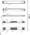
- the fan assemblies 26, 38 include a first intake 86, an exhaust 90, and a second intake 94.
- the fan assemblies 26, 38 are rotated 180° to show the various structural features and shape of the device according to some aspects of the present disclosure.
- the fan assemblies 26, 38 each include a rear assembly panel 102 coupled to an assembly cover panel 146 that define the one or more intakes and exhausts in addition to the fixing members used to mount the internal hardware and the fan assemblies to the refrigerator 10, respectively.
- the dimensions of the fan assemblies 26, 38 may include a width (X) of about 20 mm to about 60 mm or about 30 mm to about 50 mm. In some aspects, the width (X) of the fan assembly may be about 30 mm, about 40 mm, about 50 mm.
- the height (Y) of the fan assembly 26, 38 may range from about 200 mm to about 600 mm or about 300 mm to about 500 mm. In some aspects, the height (Y) of the fan assembly may be about 300 mm, about 350 mm, about 398 mm, about 425 mm, or about 450 mm.
- the depth (Z) of the fan assembly 26, 38 may range from about 5 mm to about 25 mm or about 10 mm to about 20 mm. In some aspects, the depth (Z) of the fan assembly may be about 10 mm, about 15 mm, or about 20 mm. In some aspects, the height (Y) is 398 mm, the width (Z) is about 40 mm, and the depth (Z) is about 16 mm.
- the dimensions of the cabinet cavity 82 may include a width (a) from about 20 mm to about 60 mm or from about 30 mm to about 50 mm. In some aspects, the width (a) of the cabinet cavity 82 may be about 30 mm, about 40 mm, or about 50 mm.
- the height (b) of the cabinet cavity 82 may range from about 200 mm to about 600 mm or from about 300 mm to about 500 mm. In some aspects, the height (b) of the cabinet cavity 82 may be about 300 mm, about 350 mm, about 398 mm, about 425 mm, or about 450 mm.
- the depth (c) of the cabinet cavity 82 may range from about 5 mm to about 25 mm, or from about 10 mm to about 20 mm. In some aspects, the depth (c) of the cabinet cavity 82 may be about 10 mm, about 15 mm, or about 20 mm. In some aspects, the height (b) is 399 mm, the width is about 41 mm, and the depth is about (c) is about 17 mm.
- the rear assembly panel 102 includes a distal portion 106 at each end of the rear assembly panel 102 and a central portion 110.
- the rear assembly panel 102 further includes one or more cover fixing members 114, two or more fan fixing members 118, a power cable pass through 122 and an assembly fixing member 126.
- the one or more cover fixing members 114 may be used to couple the assembly cover panel 146 (see FIG. 6A ) when used in combination with one or more coupling members.
- the coupling members 172 see FIG.
- the two or more fan fixing members 118 may be used to couple the two or more circulation fans 46 to the rear panel assembly when used in combination with one or more coupling members 172.
- the assembly fixing members 126 may be used to couple the rear assembly panel 102 to the cabinet cavity 82 of the storage compartment 22.
- One or more coupling members 172 may be used in combination with the assembly fixing members 126 to position and retain the rear assembly panel 102 in the cabinet cavity 82.
- the assembled rear panel assembly 128 includes the rear assembly panel 102 coupled to the circulation fans 46 positioned at each distal portion 106 of the rear assembly panel 102.
- the rear assembly panel 102 is coupled to an LED panel 130 having one or more LEDs 58.
- the one or more LEDs 58 may project visible light, UV-A light, UV-B light, UV-C light, or a combination thereof onto the photocatalyst 54.
- the assembled rear assembly panel 128 is simplified by being able to weld both an external power supply cable 134 and device wiring 138 to LED conductive tracks 142 of the LED panel 130 and the circulation fans 46.
- one or more LED panels 130 having one or more UV LEDs 58 and/or white light LEDs 58 may be coupled and wired into the rear assembly panel 102.
- the assembled rear panel assembly 128 may include one LED panel 130 having white light LEDS for ambient lighting in the refrigerator 10 and a second LED panel 130 having UV LEDs 58 used to activate the photocatalyst 54 of the activated filter 50 (see FIG. 2 ).
- the number of LED panels 130 and/or corresponding LEDs are not meant to be limiting and may be varied depending on the final design and corresponding functionality of the refrigerator 10.
- the assembly cover panel 146 includes two distal portions 106 and the central portion 110.
- the assembly cover panel 146 additionally includes a cover fixing member 150, a first distal vent 154, a second distal vent 158, and a central vent 162.
- the assembly cover panel 146 also includes two or more side panels 166 to help couple and position the assembly cover panel 146 to the assembled rear panel assembly 102 (see FIG. 5B ) in addition to forming side walls.
- the first and second distal vents 154, 158 may have a square shape with a height and width designed to match the size, intake and/or pull of the circulation fans 46.
- the height and width of the first and second distal vents 154, 158 may range from about 20 mm to about 250 mm, from about 20 mm to about 150 mm, or from about 20 mm to about 50 mm.
- the height and width of the first and second distal vents 154, 158 may be about 50 mm, about 40 mm, or about 30 mm.
- the length of the activated filter may range from about 100 mm to about 130 mm. In some aspects, the activated carbon filter may have a length of about 115 mm and a width of about 38 mm.
- the shape and associated dimensions of the distal vents 154, 158 and central filter vent 162 are not meant to be limiting and may be changed to meet the desired design and properties of the refrigerator 10.
- the assembly cover panel 146 is coupled to the activated filter 50.
- the activated filter 50 may include a framing member 170 used to stabilize the edges of the activated filter 50 and facilitate coupling of the activated filter 50 to the assembly cover panel 146.
- a first circulation fan 46a and a second circulation fan 46b are coupled to the rear assembly panel 102 through the fan fixing members 118 and coupling member 172 in addition to the LED panel 130 including the plurality of LEDs 58.
- the side panels 166 and end side panels 174 are positioned with respect to each other to butt up against each other to form a uniform side wall for the fan assemblies 26, 38.
- the fan assemblies 26, 38 are then positioned into the cabinet cavity 82 where the fan assembly 26, 38 may be positioned flush with the interior surface 30 of the cabinet walls 34, 42 or refrigerator doors 18a, 18b (see FIG. 1D ).
- the cabinet cavity 82 may be coupled to a flat interior surface 30 on the cabinet walls 34, 42 where the installed fan assemblies 26, 38 would stick out from the interior surface 30 to form a ledge or protrusion from the cabinet walls 34, 42.
- the cabinet cavity 82 may be a cutout or indentation in the cabinet walls 34, 42 where the interior surface 30 forms an indentation formed to receive the fan assemblies 26, 38 to form an even or flat surface on the cabinet walls 34, 42.
- first and second fan assemblies 26, 38 are each positioned in the cabinet cavity 82 on the interior surface 30 of the first and second cabinet walls 34, 42. In other aspects, the first and second fan assemblies 26, 38 may each be positioned on a front lip or edge of the cabinet cavity 82 on the interior surface 30 of the first and second cabinet walls 34, 42 configured to direct the air circulation path 62 (see FIG. 2 ) and corresponding fresh outside air into the first and second fan assemblies 26, 38 before entering the cabinet cavity 82.
- the activated filter 50 may be formed by coating, coupling, and/or adsorbing the photocatalyst 54 onto a filter.
- the filter or filter membrane may be made from a polymer fiber, a glass fiber, a ceramic fiber, or a combination thereof.
- the polymer fiber may include polyethylene (PE), polypropylene (PP), polyester, polyamide, polyvinylpolypyrrolidone (PVPP), polystyrene, polyimides, naturally occurring polymers, thermoplastics, thermosets, or combinations thereof.
- the polymer fiber used to make the filter is polyethylene or a blend of polyethylene.
- the activated filter 50 is a polymeric filter coupled to a UV activated photocatalyst.
- the photocatalyst 54 and UV activated photocatalyst may include titanium dioxide (TiO 2 ), zinc oxide (ZnO), tin oxide (SnO 2 ), cesium oxide (CeO 2 ), zinc titanium dioxide (ZnTiO 2 ), copper titanium dioxide (CuTiO 2 ), silver titanium dioxide (AgTiO 2 ), iron titanium dioxide (FeTiO 2 ), or combinations thereof.
- the photocatalyst 54 includes titanium dioxide (TiO 2 ).
- the photocatalyst 54 may be coated, coupled, and/or adsorbed onto the filter using a variety of techniques including, for example, a sol gel approach.
- the activated filter 50 includes a polyethylene filter having a photocatalytic titanium dioxide (TiO 2 ) film deposited on its surface forming a nanostructured TiO 2 layer using sol gel.
- the activated filter 50 may further include an activated carbon and/or carbon black particles used to help filter the polluted air.
- the activated filter 50 is an activated carbon filter coupled to a titanium oxide (TiO 2 ) doped sol gel.
- the TiO 2 or other photocatalyst 54 doped sol gel may include any sol gel or sol gel technique or method known in the art.
- the rear assembly panel 102 and the assembly cover panel 146 may both be coupled to the photocatalyst 54 to provide an activated surface.
- the photocatalyst 54 may be operatively coupled to the rear assembly panel 102 and/or the assembly cover panel 146 using sol gel techniques or any other coating applications known by one skilled in the art (e.g., spin coating, solvent evaporation, spray coating, brushing, etc.).
- the LEDs 58 mounted on the LED panel 130 may be positioned or spaced apart from the activated filter 50 by from about 0.5 cm to about 4 cm or from about 1 cm to about 3 cm. In some aspects, the LEDs 58 may be spaced apart from the activated filter 50 by about 0.5 cm, about 1 cm, about 1.5 cm, about 2 cm, about 2.5 cm, about 3 cm, about 3.5 cm, or about 4 cm. In some aspects, the LED panel 130 and corresponding LEDs 58 may be mounted or positioned directly in front of the activated filter 50 having the photocatalyst 54. In some aspects, the LEDs 58 generate UV light that can kill bacteria without the use of the photocatalyst 54.
- the photocatalyst 54 is activated when exposed to UV and/or visible light generated and projected by the LEDs 58 where the activated photocatalyst 54 may be able to kill and/or damage the bacteria.
- the LEDs 58 can project a wavelength from about 100 nm to about 405 nm, from about 250 nm to about 405 nm, from about 280 nm to about 405 nm, from about 315 nm to about 405 nm, from about 365 nm to about 405 nm, or from about 395 nm to about 405 nm.
- the plurality of LEDs 58 are UV-A LEDs that are positioned to project UV-A light on the activated filter 50. In other aspects, the plurality of LEDs 58 are UV-B LEDs that are positioned to project UV-B light on the activated filter 50. In still other aspects, the plurality of LEDs 58 are UV-C LEDs that are positioned to project UV-C light on the activated filter 50. In some aspects, the plurality of LEDs 58 are positioned to project UV-A light (315 nm to 400 nm), UV-B light (280 nm to 315 nm), UV-C light (100 nm to 280 nm), or a combination thereof on the activated filter 50.
- the LEDs 58 may project UV-A, UV-B, UV-C, or a combination of light thereof and/or visible light in the range from about 400 nm to about 700 nm. In still other aspects, the LEDs 58 may project visible light in the range from about 400 nm to about 700 nm.
- two or more fan assemblies 26, 38 may be required to provide the air circulation path 62 necessitated to remove a higher percentage of airborne bacteria 66, particulate matter 70, volatile organic compounds (VOCs), and molds from the storage compartment 22 of the refrigerator 10.
- VOCs volatile organic compounds
- the use of just one circulation fan or fan assembly may be unable to provide an air circulation path that can effectively eliminate enough of the airborne bacteria 66 and particulate matter 70.
- two or more fan assemblies 26, 38 may be positioned on opposing first and second cabinet walls 34, 42, positioned on the first and second doors 18a, 18b, or positioned on any two opposing interior surfaces where the first and second fan assemblies 26, 38 work in a complementary manner to provide the improved air circulation path 62.
- the first and second cabinet walls 34, 42 are opposing walls or walls that are facing each other to complementary circulate the air present in or coming into the storage compartment 22.
- the air circulation path 62 may better direct the airborne bacteria 66, particulate matter 70, volatile organic compounds (VOCs), and molds into the first and second fan assemblies 26, 38 to be filtered.
- the first cabinet wall 34 opposes the second cabinet wall 42.
- the air circulation path 62 is configured to direct bacteria throughout the central area of the storage compartment 22
- the combination of the first and second fan assemblies 26, 38 are configured to provide the air circulation path 62 that directs the airborne bacteria 66, particulate matter 70, volatile organic compounds (VOCs), and/or molds simultaneously or contemporaneously into the fan assemblies 26, 38 using the two or more circulation fans 46 to direct the polluted air through the activated filter 50 irradiated by UV and/or visible light projected from the LEDs 58 to filter and clean the polluted air to circulate filtered air into the storage compartment 22 of the refrigerator 10.
- VOCs volatile organic compounds
- the two or more circulation fans 46 are configured to direct the air circulation path 62 in through the two or more circulation fans 46 and out through the activated filter 50 where the air circulation path 62 is configured to direct bacteria positioned in the central area of the storage compartment 22 into the first and second fan assemblies 26, 38.
- the various aspects of the fan assemblies 26, 38 disclosed herein generally direct the air circulation path 62 into the fan assemblies 26, 38 using the two or more circulation fans 46
- the two or more circulation fans 46 are configured to direct the air circulation path 62 in through the activated filter 50 and out through the two or more circulation fans 46.
- the reversal of the air circulation path 62 is considered to be within the scope of the disclosure of the present invention.
- the first and second fan assemblies 26, 38 are able to provide at least a 50 % microbial reduction in one minute, at least a 50 % microbial reduction in three minutes, or at least a 50 % microbial reduction in ten minutes. In other aspects, the first and second fan assemblies 26, 38 are able to provide at least a 60 % microbial reduction in one minute, at least a 60 % microbial reduction in three minutes, or at least a 60 % microbial reduction in ten minutes.
- the first and second fan assemblies 26, 38 are able to provide at least a 70 % microbial reduction in one minute, at least a 70 % microbial reduction in three minutes, or at least a 70 % microbial reduction in ten minutes. In other aspects, the first and second fan assemblies 26, 38 are able to provide at least an 80 % microbial reduction in one minute, at least an 80 % microbial reduction in three minutes, or at least an 80 % microbial reduction in ten minutes.
- the fan assemblies 26, 38 may include the first intake 86, a first exhaust 90a, the second intake 94, a second exhaust 90b, and a third intake 178.
- the number of intakes and the number of exhausts may be limited to the number of circulation fans 46 and activated filters 50 incorporated into the fan assembly 26, 38 based on the design and/or final air circulation properties desired for the refrigerator 10.
- the number of intakes may be two, three, four or more while the number of exhausts may include one, two, three, four, or more where the intakes and exhausts may be positioned with respect to each other in any combination.
- FIG. 8B an exploded side view of the fan assemblies 26, 38 provided in FIG. 8A and corresponding refrigeration liner 82 is provided.
- the assembly cover panel 146 is coupled to two activated filters 50a, 50b having framing members to stabilize the edges and facilitate coupling of the activated filters 50a, 50b to the assembly cover panel 146.
- the assembly cover panel 146 includes a first fan vent 154, a first filter vent 162a, a second fan vent 158, a second filter vent 162b, and a third filter vent 182.
- the first circulation fan 46a, second circulation fan 46b, and a third circulation fan 46c are coupled to the rear assembly panel 102 using coupling members 172 in addition to a first LED panel 130a having a plurality of white light LEDs 186.
- a second LED panel 130b having the plurality of UV LEDs 58 is also positioned on the rear panel assembly 102 to project UV light on the photocatalyst 54 of the activated filters 50a, 50b.
- the side panels 166 and end side panels 174 are positioned up against each other to form solid siding portions for the fan assemblies 26, 38.
- the fan assemblies 26, 38 may be then positioned into the cabinet cavity 82 where the fan assembly 26, 38 may be positioned flush with the interior surface 30 of a cabinet wall 34, 42 or refrigerator doors 18a, 18b.
- an air purifying fan assembly 26 is provided.
- the air purifying fan assembly 26 includes the rear assembly panel 102 and the assemble cover panel 146.
- the assemble cover panel 146 includes one or more air intakes 86, 94 and one or more air exhausts 90a, 90b; one or more circulation fans 46 positioned inside the rear assembly panel 102 and the assemble cover panel 146 and adjacent to the one or more air intakes 86, 94 or one or more air exhausts 90a, 90b; one or more activated filters 50 having a sol gel photocatalyst 54 and the activated carbon.
- the activated filter 50 is positioned in line or directly across from the one or more air exhausts and one or more LEDs 58 positioned to project light on the activated filter 50.
- the following examples and their corresponding data represent certain non-limiting examples of the first and second fan assemblies 26, 38 used in conjunction with each other to effectively filter air in the storage compartment 22 of the refrigerator 10.
- the antibacterial refrigerator 10 and its corresponding air purifying assemblies defined by the fan assemblies 26, 38 and/or the air purifying duct assembly 192 are designed to remove contaminants such as odor, toxic particles, and pathogens. Examples of key substances that are typically removed through this air-treatment process include parasites, bacteria, algae, viruses, fungi, ethylene, and other food related chemical pollutants.
- the inoculum solution used in the experiments illustrated in FIG. 9A includes a microbial-loaded saline solution (50-70 ml) recovered during hand washing procedures.
- a microbial-loaded saline solution 50-70 ml recovered during hand washing procedures.
- the count of viable microorganisms was determined by means of the pour plate culture method.
- the inner compartment of a refrigerator (Whirlpool, BLFV8121W model) and the antibacterial device were first cleaned to remove any gross contamination using a quaternary benzyl ammonium disinfectant where the same cleaning procedure was performed on the storage compartment 22 in between each experiment.
- the antibacterial device was placed inside the refrigerator and the refrigerator was left to equilibrate at 40°C for at least 24 hours.
- the experiments included the nebulization of 450 microliters ( ⁇ L) of inoculum inside the refrigerator through a small hole made on the front wall of the refrigerator door ( ⁇ 1.2 cm).
- a test air filtration device 190 was switched on and kept running for a variety of different time periods (e.g., 1 min, 3 min, 10 min) after a microbial nebulization. Control experiments were carried out in the same conditions, but the test air filtration device 190 was not activated.
- the LB-agar petri dishes 78 were closed about 10 minutes after the microbial nebulization and incubated for the first 24 hrs at 37°C, and then for an additional 48 hrs at room temperature (RT). The number of viable microorganisms was then counted on LB-agar petri dishes. All of the experiments noted were performed in triplicate. Data was normalized with respect to the number of viable counts and control samples (CTRL, e.g., air filtration device turned off), considering the number of microorganisms in such condition as 100%. Results are expressed as mean ⁇ standard deviation (SD).
- CFU colony forming units
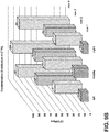
- the row of LP-agar petri dishes 78 positioned closest to the test air filtration device 190 contained the highest microbial population relative to Rows 1-3 while lowest microbial population was observed in the row furthest from the test air filtration device 190 (Row 1).
- the uniform difference and disparity in microbial populations based on the difference in distance between the corresponding rows and the test filtration device 190 supports the need for two or more air filtration devices 26, 38 as described herein.
- the viable CFU counts for each of the four rows were averaged and plotted against time as the test air filtration device 190 was operated to filter the storage compartment 22. Consistent with the data provided in FIG. 9B , when the filtration device was run for a longer period of time (e.g., 10 min vs. 3 min vs 1 min), the number of microorganisms decreased from about 50 to about 75% already after one minute and was generally maintained over the longer periods of time. Again consistent with the data provided in FIG. 9B , the decrease in CFU counted is dependent on the distance from the test air filtration device 190 where the decrease in CFU was more pronounced or greater at distances further away from the test air filtration device 190.
- a longer period of time e.g. 10 min vs. 3 min vs 1 min
- FIG. 10 an assessment of the in vitro time-dependent reduction of a microbial population after exposure to different activated filters 50 having the photocatalyst 50 including a TiO 2 doped sol gel.
- the antibacterial effectiveness of a variety of filters was assessed using three different filters: 1) Filter 1, a polymeric filter having no photocatalyst 50 incorporated, 2) Filter 2, a polymeric filter treated with a first TiO 2 doped sol gel as the photocatalyst 50; and 3) Filter 3, a polymeric filter treated with a second TiO 2 doped sol gel as the photocatalyst 50.
- the activated filters 50 were put in contact with E.
- d H2O sterile deionized water
- test specimens were brought into contact with the inoculum suspension.
- the experiments were carried out according to the ASTM E 2315 (Assessment of Antimicrobial Activity Using a Time-Kill Procedure) [1] and ISO 22196 (Measurement of antibacterial activity on plastics and other non-porous surfaces) [2] standards, with slight modifications that are in the 10 3 times higher bacterial load and the temperature at which the experiments were performed ( e.g ., 4 °C instead of 35 ⁇ 1 °C).
- the Filters 2 and 3 having the photocatalyst 54 added using a sol gel approach underwent UV irradiation (i.e ., the final device setup). Bacteria inoculated in wells without any filter were used as positive controls (untreated bacteria).
- the antibacterial effectiveness of the three filters/devices was evaluated using the Time-Kill procedure, assessed by measuring the reduction of the microbial population over time. The results are illustrated in FIG. 10 .
- the highest antimicrobial activity was observed for the Filter 2 and 3 activated filters 50 having the photocatalyst 54. After 30 min of incubation for Filters 2 and 3, no viable bacteria was detected. As the maximum efficiency was found at the shortest duration, this antibacterial behavior was maintained thereafter for Filters 2 and 3.
- FIGS. 11A and 11B a test monitoring the Total Solid Particulate (TSP) and Volatile Organic Compounds (VOC) in a confined environment that is artificially polluted to evaluate the effectiveness of different decontamination devices for household refrigerators is illustrated.
- TSP Total Solid Particulate
- VOC Volatile Organic Compounds
- Tests were performed in a Glove Box (100 liters per volume) that was polluted by burning about 1 ⁇ 4 of a Marlboro cigarette that was able to rapidly generate a large amount of TSP and VOC.
- the following testing procedure was used: ignition of cigarette, immediate closure of the Glove Box, cigarette combustion, waiting for 15 minutes, switching on the Ozonetor or filter fan, monitoring of up to 120 minutes of TSP content using an Aerocet 531, Met One Instruments, Inc., or monitoring up to 120 minutes of VOC content using a DSIAQ-PLUS-PPC, Gray Wolf Sensing Solutions.
- the static control and Ozonetor treatments each were able to reduce the VOC by up to 15 % over 120 minutes and had no significant decrease in the TSP during the duration of the experiment.
- the Filter 1 polymeric filter having no photocatalyst 50 incorporated was able to reduce the VOC by up to about 20 % over 120 minutes and the TSP by up to 40 % over 120 minutes.
- the Filter 2 activated with UV LEDs using a polymeric filter treated with a first TiO 2 doped sol gel as the photocatalyst 50 was able to reduce the VOC by up to about 20 % over 120 minutes and the TSP by up to 50 % over 120 minutes.
- the Filter 3 activated with UV LEDs using a polymeric filter treated with a first TiO 2 doped sol gel as the photocatalyst 50 was able to reduce the VOC by up to about 20 % over 120 minutes and the TSP by up to 50 % over 120 minutes.
- the activated filter 50 coupled to the photocatalyst 54 may be able to reduce the VOCs in the storage compartment 22 of the refrigerator 10 by up to about 10 %, about 15 %, about 20 %, or about 25 % in 40 minutes, 60 minutes, 80 minutes, 100 minutes, or 120 minutes or less.
- the activated filter 50 coupled to the photocatalyst 54 e.g.
- TiO 2 ) that is activated using UV LEDs 58 may be able to reduce the TSP in the storage compartment 22 of the refrigerator 10 by up to about 10 %, about 15 %, about 20 %, about 25 %, about 30 %, about 35 %, about 40 %, or about 45 %, in 40 minutes, 60 minutes, 80 minutes, 100 minutes, or 120 minutes or less.
- a refrigerator includes a cabinet coupled to one or more doors forming a storage compartment.
- a first fan assembly is positioned on an interior surface of a first cabinet wall.
- a second fan assembly is positioned on the interior surface of a second cabinet wall.
- the first and second fan assemblies each include two or more circulation fans.
- a filter is coupled to a photocatalyst to form an activated filter.
- a plurality of LEDs are positioned to project light on the activated filter.
- An air circulation path is configured to direct airborne bacteria and particulate matter within the storage compartment contemporaneously into the first and second fan assemblies using the two or more circulation fans and circulate filtered air into the storage compartment through the activate filter disposed in the air circulation path.
- a plurality of LEDs project visible light, UV-A light, UV-B light, UV-C light, or a combination thereof onto a photocatalyst.
- an activated filter is an activated carbon filter coupled to a titanium oxide (TiO 2 ) doped sol gel.
- an activated filter is a polymeric filter coupled to a UV activated photocatalyst.
- a second cabinet wall opposes a first cabinet wall.
- two or more circulation fans are configured to direct an air circulation path in through the two or more circulation fans and out through an activated filter.
- two or more circulation fans are configured to direct an air circulation path in through an activated filter and out through the two or more circulation fans.
- first and second fan assemblies are each positioned in a cabinet cavity on an interior surface of first and second cabinet walls.
- airborne bacteria and particulate matter are reduced by at least 60% within one minute.
- a photocatalyst is titanium dioxide (TiO 2 ).
- a refrigerator includes a cabinet coupled to one or more doors.
- the cabinet includes a storage compartment.
- Two or more fan assemblies are positioned on an interior surface of the cabinet, the one or more doors, or a combination thereof.
- the fan assemblies each comprise one or more circulation fans.
- a photocatalyst is coupled to one or more filters forming an activated filter.
- a plurality of LEDs are positioned to project light on the light activated photocatalyst.
- An air circulation path is configured to direct airborne bacteria and particulate matter within the storage compartment contemporaneously into the two or more fan assemblies using the one or more circulation fans and circulate filtered air into the storage compartment through the activate filter disposed in the air circulation path.
- a plurality of LEDs project visible light, UV-A light, UV-B light, UV-C light, or a combination thereof onto a photocatalyst.
- two or more fan assemblies are positioned on two or more interior surfaces of opposing cabinet walls or proximate an edge of a cabinet.
- one or more circulation fans are configured to direct an air circulation path in through one or more intakes of a fan assembly and out through one or more exhausts.
- one or more circulation fans includes two, three, or four circulation fans.
- airborne bacteria and/or odor are reduced by at least 60% within ten minutes.
- an antibacterial fan assembly includes a rear assembly and an assembly cover panel.
- the assembly cover panel includes one or more air intakes and one or more air exhausts.
- One or more circulation fans are positioned between the rear assembly panel and the assembly cover panel.
- An activated filter has a photocatalyst and an activated carbon. The activated filter is positioned in circulation with the one or more air exhausts.
- One or more LEDs are positioned to project light on the activated filter.
- LEDs are positioned to illuminate an activated filter using a UV wavelength from about 280 nm to about 405 nm.
- one or more circulation fans are configured to direct an air circulation path configured to direct airborne bacteria and particulate matter within a storage compartment contemporaneously into two or more antibacterial fan assemblies using the one or more circulation fans and circulate filtered air into the storage compartment through an activated filter disposed in the air circulation path.
- a photocatalyst is a titanium oxide (TiO 2 ) doped sol gel.
- first and second fan assemblies each include a rear assembly panel coupled to an assembly cover panel.
- an assembly cover panel defines one or more intakes and one or more exhausts or a fan assembly.
- first and second fan assemblies are configured to provide at least a 50 % microbial reduction in one minute.
- first and second fan assemblies are configured to provide at least a 50 % microbial reduction in ten minutes.
- the term "coupled” in all of its forms, couple, coupling, coupled, etc. generally means the joining of two components (electrical or mechanical) directly or indirectly to one another. Such joining may be stationary in nature or movable in nature. Such joining may be achieved with the two components (electrical or mechanical) and any additional intermediate members being integrally formed as a single unitary body with one another or with the two components. Such joining may be permanent in nature or may be removable or releasable in nature unless otherwise stated.
- elements shown as integrally formed may be constructed of multiple parts or elements shown as multiple parts may be integrally formed, the operation of the interfaces may be reversed or otherwise varied, the length or width of the structures and/or members or connector or other elements of the system may be varied, the nature or number of adjustment positions provided between the elements may be varied.
- the elements and/or assemblies of the system may be constructed from any of a wide variety of materials that provide sufficient strength or durability, in any of a wide variety of colors, textures, and combinations. Accordingly, all such modifications are intended to be included within the scope of the present innovations. Other substitutions, modifications, changes, and omissions may be made in the design, operating conditions, and arrangement of the desired and other exemplary embodiments without departing from the spirit of the present innovations.
Landscapes
- Engineering & Computer Science (AREA)
- Chemical & Material Sciences (AREA)
- Combustion & Propulsion (AREA)
- Physics & Mathematics (AREA)
- Mechanical Engineering (AREA)
- Thermal Sciences (AREA)
- General Engineering & Computer Science (AREA)
- Chemical Kinetics & Catalysis (AREA)
- Health & Medical Sciences (AREA)
- Epidemiology (AREA)
- Life Sciences & Earth Sciences (AREA)
- Animal Behavior & Ethology (AREA)
- General Health & Medical Sciences (AREA)
- Public Health (AREA)
- Veterinary Medicine (AREA)
- Cold Air Circulating Systems And Constructional Details In Refrigerators (AREA)
Abstract
Description
- The present invention generally relates to an air filtration system for a refrigerator, and more specifically, to air purifying assemblies used in conjunction to filter microbes, volatile organic compounds, and particulate matter from a refrigerator.
- With the latest development of extra-large capacity refrigerators, there has been an emerging demand for highly robust antimicrobial technology such as air disinfection systems for food preservation and related features. Such systems are used to avoid the spoilage of food and produce stored in refrigerators for extended periods. Due to the unavailability of adequate antimicrobial technology, huge amounts of food, including produce, can go wasted even when stored in adequately low temperature refrigerators. Moreover, because of the increasing cost of commodities and food product costs, consumers are demanding efficient food storage technology for its longevity without compromise to its freshness.
- One food preservation technique currently being used includes titanium dioxide (TiO2) charged using a mercury lamp lighting system but due to the harmful effects of the mercury lamp integrated in this system, it could not meet the specifications or expectations for an antimicrobial application. In addition, the use of mercury in these types of UV lamp systems could be extremely dangerous due to health hazards and other handling issues associated with mercury. Other preservation and antimicrobial techniques being used include ozonizer systems that are directly integrated into the refrigerator. However, with time, significant decline in ozonizer performance is reported and their high cost makes these applications prohibitively expensive. Nano-misting techniques have also been studied but due to the harmful nature of the zinc and silver used in the applied nano-particles; these materials also did not meet consumer market requirements.
- Accordingly, the need for an efficient and affordable antimicrobial filtration system is required in the market place for consumers to better accommodate food safety and longer storage times for valuable foodstuffs.
- According to one aspect of the present disclosure, a refrigerator is provided. The refrigerator includes a cabinet coupled to one or more doors forming a storage compartment; a first fan assembly positioned on an interior surface of a first cabinet wall; and a second fan assembly positioned on the interior surface of a second cabinet wall. The first and second fan assemblies each include: two or more circulation fans; a filter coupled to a photocatalyst to form an activated filter; and a plurality of LEDs positioned to project light on the activated filter. The refrigerator also includes an air circulation path configured to direct airborne bacteria and particulate matter within the storage compartment contemporaneously into the first and second fan assemblies using the two or more circulation fans and circulate filtered air into the storage compartment through the activated carbon filter disposed in the air circulation path.
- According to another aspect of the present disclosure, a refrigerator is provided. The refrigerator includes a cabinet coupled to one or more doors. The cabinet includes a storage compartment; two or more fan assemblies positioned on an interior surface of the cabinet, the one or more doors, or a combination thereof. The fan assemblies each include: one or more circulation fans; a photocatalyst coupled to one or more filters to form an activated filter; and a plurality of LEDs positioned to project light on the activated filter. An air circulation path is configured to direct airborne bacteria and particulate matter within the storage compartment contemporaneously into the two or more fan assemblies using the one or more circulation fans and circulate filtered air into the storage compartment through the activated filter disposed in the air circulation path.
- According to still another aspect of the present disclosure, an antibacterial fan assembly is provided. The antibacterial fan assembly includes a rear assembly panel and an assembly cover panel wherein the assembly cover panel includes one or more air intakes and one or more air exhausts. The antibacterial fan assembly further includes one or more circulation fans positioned between the rear assembly panel and the assembly cover panel and an activated filter having a photocatalyst and an activated carbon. The activated filter is positioned in circulation with the one or more air exhausts. The antibacterial fan assembly also includes one or more LEDs positioned to project light on the activated filter.
- These and other aspects, objects, and features of the present disclosure will be understood and appreciated by those skilled in the art upon studying the following specification, claims, and appended drawings.
- In the drawings:
-
FIG. 1A is a front isometric view of a refrigerator having bacteria contaminated food; -
FIG. 1B is a front isometric view of a refrigerator having no food; -
FIG. 1C is a front isometric view of a refrigerator having a standard circulation fan; -
FIG. 1D is a front isometric view of a refrigerator having a first fan assembly and a second fan assembly according to some aspects of the disclosure; -
FIG. 2 is a partially schematic fragmentary view of the fan assembly taken at location II inFIG. 1D ; -
FIG. 3 is a rotating isometric view of a fan assembly according to some aspects of the present disclosure; -
FIG. 4A provides front and side view images of the fan assembly according to some aspects of the present disclosure; -
FIG. 4B provides front and side views of a refrigeration cabinet cavity according to some aspects of the present disclosure; -
FIG. 5A is a front view of a rear assembly panel according to some aspects of the present disclosure; -
FIG. 5B is a front view of an assembled rear panel assembly according to some aspects of the present disclosure; -
FIG. 6A is a rear isometric view of an assembly cover panel according to some aspects of the present disclosure; -
FIG. 6B is a rear view of the assembly cover panel provided inFIG. 6A according to some aspects of the present disclosure; -
FIG. 7 is an exploded side view of a fan assembly and refrigeration liner according to some aspects of the present disclosure; -
FIG. 8A is a front view of an alternative embodiment of a fan assembly according to some aspects of the present disclosure; -
FIG. 8B is an exploded side view of the fan assembly provided inFIG. 8A according to some aspects of the present disclosure; -
FIG. 9A is a picture of the experimental set up of the nebulization of an inoculum solution using a fan assembly for fan filtration according to some aspects of the present disclosure; -
FIG. 9B is a distribution of microbial populations in a control using one fan assembly; -
FIG. 9C provides averages of the distribution of microbial populations at various different times; -
FIG. 10 is a quantification of viable bacteria after incubation with different air filters at different time intervals; -
FIG. 11A provides a plot of the percentage of volatile organic compounds over a period of time using different air filters according to some aspects of the present disclosure; and -
FIG. 11B provides the percentage of total solid particulates over a period of time using different filtration systems according to some aspects of the present disclosure. - For purposes of description herein the terms "upper," "lower," "right," "left," "rear," "front," "vertical," "horizontal," and derivatives thereof shall relate to the device as oriented in
FIG. 1 . However, it is to be understood that the device may assume various alternative orientations and step sequences, except where expressly specified to the contrary. It is also to be understood that the specific devices and processes illustrated in the attached drawings, and described in the following specification, are simply exemplary embodiments of the inventive concepts defined in the appended claims. Hence, specific dimensions and other physical characteristics relating to the embodiments disclosed herein are not to be considered as limiting, unless the claims expressly state otherwise. - As used herein, the term "and/or," when used in a list of two or more items, means that any one of the listed items can be employed by itself, or any combination of two or more of the listed items can be employed. For example, if a composition is described as containing components A, B, and/or C, the composition can contain A alone; B alone; C alone; A and B in combination; A and C in combination; B and C in combination; or A, B, and C in combination.
- Referring to
FIGS. 1A-11B , thereference numeral 10 refers to a refrigerator. Therefrigerator 10 includes acabinet 14 coupled to one ormore doors 18 forming astorage compartment 22. Therefrigerator 10 additionally includes afirst fan assembly 26 positioned on aninterior surface 30 of afirst cabinet wall 34, and asecond fan assembly 38 positioned on theinterior surface 30 of asecond cabinet wall 42. The first andsecond fan assemblies more circulation fans 46; a filter coupled to aphotocatalyst 54 to form an activatedfilter 50; and a plurality of light emitting diodes (LEDs) 58 positioned to project light on the activatedfilter 50. Anair circulation path 62 configured to direct air bornbacteria 66 andparticulate matter 70 within thestorage compartment 22 contemporaneously into the first andsecond fan assemblies more circulation fans 46 and circulate filtered air into thestorage compartment 22 through the activatedfilter 50 disposed in theair circulation path 62. - The first and
second fan assemblies filter 50 and corresponding UV and/orvisible light LEDs 58. The technology incorporated into thesefan assemblies filter 50 andLEDs 58 providing an efficient air treatment capability that may interact with the deoxyribonucleic acid (DNA) and/or trigger a cascade of other biological reactions in harmful bacteria responsible for the spoilage of food stored at low temperatures in refrigerators. The disclosure herein provides a series of experiments performed according to the ASTM E 2315 and ISO 22196 international standards using minor modifications. In some aspects, the activatedfilter 50 includes thephotocatalyst 54 made up of a photocatalytic nanostructured titanium dioxide (TiO2) film, coating, or membrane deposited using sol-gel. The sol-gel is doped to impart the titanium dioxide (TiO2) as thephotocatalyst 54 that may be activated using visible light and/or an ultraviolet wavelength less than 833 nanometers (e.g., 280-700 nanometer wavelengths) using a 12 volt UV LED strip or panel (seeFIG. 5B ) is provided. In some aspects, the activatedfilter 50 and correspondingphotocatalyst 54 may be activated using an ultraviolet wavelength less than about 400 nm and/or visible light ranging from about 390 nm to about 700 nm. - Referring now to
FIGS. 1A-1D , a variety of different refrigerator environments were studied to determine how bacteria and other particulate matter may be introduced into thestorage compartment 22 of therefrigerator 10. Each of therefrigerators 10 is shown having thecabinet 14 with thestorage compartment 22 enclosed by thecabinet 14 and a first andsecond door FIG. 1A , the introduction of bacterial contamination to thestorage compartment 22 was accomplished by positioning a contaminatedchicken breast 74 containing many different types of bacteria. The test environment provided inFIG. 1A demonstrated that the bacteria growing on the contaminatedchicken breast 74 did not spread to or reach any of plurality ofpetri dishes 78 proving that refrigerator bacterial contamination is likely not due to food cross-contamination, except for direct food contact. - In the second test environment illustrated in
FIG. 1B , the introduction of bacterial contamination to thestorage compartment 22 was accomplished by circulating air from outside therefrigerator 10 by opening and closing the first andsecond refrigerator doors refrigerator doors airborne bacteria 66 was introduced to thestorage compartment 22 and was able to contact and grow in thepetri dishes 78. Therefrigerator 10 inFIG. 1B did not include any air filtration or circulation system. The test environment provided inFIG. 1B demonstrates that bacteria introduced into therefrigerator 10 and corresponding foodstuffs is likely determined by the introduction ofairborne bacteria 66 duringrefrigerator door 18 opening and closing. - In the third test environment illustrated in
FIG. 1C , the introduction of bacterial contamination to thestorage compartment 22 was accomplished as described inFIG. 1B , by opening and closing therefrigerator doors FIG. 1C includes a standardair filtration system 80 using only a single fan assembly which is currently implemented in many refrigerators. The test environment provided inFIG. 1C demonstrated that the single fan assembly air filtration system had minimal to no noticeable effect on theairborne bacteria 66 introduced into thestorage compartment 22 of therefrigerator 10. - In the fourth test environment illustrated in
FIG. 1D , the introduction of bacterial contamination to thestorage compartment 22 was accomplished as described inFIGS. 1B and1C , by opening and closing therefrigerator doors refrigerator 10 inFIG. 1D additionally includes first andsecond fan assemblies circulation fans 46 and at least one activated filter 50 (seeFIG. 2 ) initiated by at least one UV LED 58 (seeFIG. 5B ). The test environment provided inFIG. 1D demonstrated that the combination of twofan assemblies storage compartment 22 by up to 70% more when compared to the environments provided inFIGS. 1B and1C . - Referring now to
FIG. 2 , a partially schematic fragmentary view of thefan assembly FIG. 1D . As shown,airborne bacteria 66 and/orparticulate matter 70 scattered throughout thestorage compartment 22 are directed along theair circulation path 62 into one of the twofan assemblies air circulation path 62 generally flows between the area of thestorage assembly 22 and the twofan assemblies more circulation fans 46 in eachfan assembly FIG. 1B ,1C, and 1D , the air introduced into thestorage compartment 22 when opening therefrigerator doors airborne bacteria 66 and/orparticulate matter 70. Once therefrigerator doors corresponding storage compartment 22 are closed, theair circulation path 62 formed by thefan assemblies airborne bacteria 66 and/orparticulate matter 70 in through thecirculation fans 46 and out through the activatedfilter 50 coupled to thephotocatalyst 54. As theairborne bacteria 66 and/orparticulate matter 70 contact the activatedfilter 50, one or more LEDs 58 (seeFIG. 5B ) can project UV and/or visible light onto thephotocatalysts 54 of the activatedfilter 50. Thephotocatalyst 54 is activated by the UV light, which can then kill and/or damage theairborne bacteria 66. Theparticulate matter 70 can additionally be removed by the activatedfilter 50. The corresponding or resultant filtered air continues along theair circulation path 62 out through thefilter 50 and back into thestorage compartment 22 of thecabinet 14. In some aspects, a controller (not shown) drives thecirculation fans 46 and LED's 58 (seeFIG. 5B ) as triggered by a preprogrammed schedule, the opening and closing of therefrigerator doors 18, the detection of odor,bacteria 66, and/orparticulate matter 70 using, for example, a bio-sensor, and/or other triggers or factors known by one skilled in the art. - Referring now to
FIG. 3 , a rotating isometric view of thefan assemblies fan assemblies first intake 86, anexhaust 90, and asecond intake 94. Thefan assemblies fan assemblies rear assembly panel 102 coupled to anassembly cover panel 146 that define the one or more intakes and exhausts in addition to the fixing members used to mount the internal hardware and the fan assemblies to therefrigerator 10, respectively. - Referring now to
FIG. 4A , front and side views of thefan assemblies fan assemblies fan assembly fan assembly - Referring to
FIG. 4B , the front and side views of thecabinet cavity 82 is provided. In some aspects, the dimensions of thecabinet cavity 82 may include a width (a) from about 20 mm to about 60 mm or from about 30 mm to about 50 mm. In some aspects, the width (a) of thecabinet cavity 82 may be about 30 mm, about 40 mm, or about 50 mm. The height (b) of thecabinet cavity 82 may range from about 200 mm to about 600 mm or from about 300 mm to about 500 mm. In some aspects, the height (b) of thecabinet cavity 82 may be about 300 mm, about 350 mm, about 398 mm, about 425 mm, or about 450 mm. The depth (c) of thecabinet cavity 82 may range from about 5 mm to about 25 mm, or from about 10 mm to about 20 mm. In some aspects, the depth (c) of thecabinet cavity 82 may be about 10 mm, about 15 mm, or about 20 mm. In some aspects, the height (b) is 399 mm, the width is about 41 mm, and the depth is about (c) is about 17 mm. - Referring now to
FIG. 5A , a front view of therear assembly panel 102 is provided according to some aspect of the present disclosure. Therear assembly panel 102 includes adistal portion 106 at each end of therear assembly panel 102 and acentral portion 110. Therear assembly panel 102 further includes one or morecover fixing members 114, two or morefan fixing members 118, a power cable pass through 122 and anassembly fixing member 126. The one or morecover fixing members 114 may be used to couple the assembly cover panel 146 (seeFIG. 6A ) when used in combination with one or more coupling members. The coupling members 172 (seeFIG. 7 ) may include any means known in the art used for coupling different members together, for example, but not limited to screws, bolts, nails, clips, snaps, and/or ties. The two or morefan fixing members 118 may be used to couple the two ormore circulation fans 46 to the rear panel assembly when used in combination with one ormore coupling members 172. Theassembly fixing members 126 may be used to couple therear assembly panel 102 to thecabinet cavity 82 of thestorage compartment 22. One ormore coupling members 172 may be used in combination with theassembly fixing members 126 to position and retain therear assembly panel 102 in thecabinet cavity 82. - Referring now to
FIG. 5B , a front view of an assembledrear panel assembly 128 is provided. The assembledrear panel assembly 128 includes therear assembly panel 102 coupled to thecirculation fans 46 positioned at eachdistal portion 106 of therear assembly panel 102. In addition, therear assembly panel 102 is coupled to anLED panel 130 having one ormore LEDs 58. The one ormore LEDs 58 may project visible light, UV-A light, UV-B light, UV-C light, or a combination thereof onto thephotocatalyst 54. The assembledrear assembly panel 128 is simplified by being able to weld both an externalpower supply cable 134 anddevice wiring 138 to LEDconductive tracks 142 of theLED panel 130 and thecirculation fans 46. Construction and wiring in this manner allows the assembledrear panel assembly 128 to be achieved using only six tin solders. In some aspects, one ormore LED panels 130 having one ormore UV LEDs 58 and/orwhite light LEDs 58 may be coupled and wired into therear assembly panel 102. For example, in some aspects, the assembledrear panel assembly 128 may include oneLED panel 130 having white light LEDS for ambient lighting in therefrigerator 10 and asecond LED panel 130 havingUV LEDs 58 used to activate thephotocatalyst 54 of the activated filter 50 (seeFIG. 2 ). The number ofLED panels 130 and/or corresponding LEDs (both UV and other wavelengths) are not meant to be limiting and may be varied depending on the final design and corresponding functionality of therefrigerator 10. - Referring now to
FIG. 6A , a rear isometric view of theassembly cover panel 146 is provided. Theassembly cover panel 146 includes twodistal portions 106 and thecentral portion 110. Theassembly cover panel 146 additionally includes acover fixing member 150, a firstdistal vent 154, a seconddistal vent 158, and acentral vent 162. Theassembly cover panel 146 also includes two ormore side panels 166 to help couple and position theassembly cover panel 146 to the assembled rear panel assembly 102 (seeFIG. 5B ) in addition to forming side walls. - Referring now to
FIG. 6B , a rear view of theassembly cover panel 146 is illustrated coupled to the activatedfilter 50. In some aspects, the first and seconddistal vents circulation fans 46. In some aspects, the height and width of the first and seconddistal vents distal vents distal vents central filter vent 162 are not meant to be limiting and may be changed to meet the desired design and properties of therefrigerator 10. - Referring now to
FIG. 7 , an exploded side view of thefan assemblies corresponding refrigeration liner 82 is provided. As illustrated, theassembly cover panel 146 is coupled to the activatedfilter 50. In some aspects, the activatedfilter 50 may include a framingmember 170 used to stabilize the edges of the activatedfilter 50 and facilitate coupling of the activatedfilter 50 to theassembly cover panel 146. Afirst circulation fan 46a and asecond circulation fan 46b are coupled to therear assembly panel 102 through thefan fixing members 118 andcoupling member 172 in addition to theLED panel 130 including the plurality ofLEDs 58. Theside panels 166 and endside panels 174 are positioned with respect to each other to butt up against each other to form a uniform side wall for thefan assemblies fan assemblies cabinet cavity 82 where thefan assembly interior surface 30 of thecabinet walls refrigerator doors FIG. 1D ). In some aspects, thecabinet cavity 82 may be coupled to a flatinterior surface 30 on thecabinet walls fan assemblies interior surface 30 to form a ledge or protrusion from thecabinet walls cabinet cavity 82 may be a cutout or indentation in thecabinet walls interior surface 30 forms an indentation formed to receive thefan assemblies cabinet walls second fan assemblies cabinet cavity 82 on theinterior surface 30 of the first andsecond cabinet walls second fan assemblies cabinet cavity 82 on theinterior surface 30 of the first andsecond cabinet walls FIG. 2 ) and corresponding fresh outside air into the first andsecond fan assemblies cabinet cavity 82. - The activated
filter 50 may be formed by coating, coupling, and/or adsorbing thephotocatalyst 54 onto a filter. In some aspects, the filter or filter membrane may be made from a polymer fiber, a glass fiber, a ceramic fiber, or a combination thereof. The polymer fiber may include polyethylene (PE), polypropylene (PP), polyester, polyamide, polyvinylpolypyrrolidone (PVPP), polystyrene, polyimides, naturally occurring polymers, thermoplastics, thermosets, or combinations thereof. In some aspects, the polymer fiber used to make the filter is polyethylene or a blend of polyethylene. In some aspects, wherein the activatedfilter 50 is a polymeric filter coupled to a UV activated photocatalyst. Thephotocatalyst 54 and UV activated photocatalyst may include titanium dioxide (TiO2), zinc oxide (ZnO), tin oxide (SnO2), cesium oxide (CeO2), zinc titanium dioxide (ZnTiO2), copper titanium dioxide (CuTiO2), silver titanium dioxide (AgTiO2), iron titanium dioxide (FeTiO2), or combinations thereof. In some aspects, thephotocatalyst 54 includes titanium dioxide (TiO2). Thephotocatalyst 54 may be coated, coupled, and/or adsorbed onto the filter using a variety of techniques including, for example, a sol gel approach. In some aspects, the activatedfilter 50 includes a polyethylene filter having a photocatalytic titanium dioxide (TiO2) film deposited on its surface forming a nanostructured TiO2 layer using sol gel. In other aspects, the activatedfilter 50 may further include an activated carbon and/or carbon black particles used to help filter the polluted air. In some aspects, the activatedfilter 50 is an activated carbon filter coupled to a titanium oxide (TiO2) doped sol gel. The TiO2 orother photocatalyst 54 doped sol gel may include any sol gel or sol gel technique or method known in the art. In some aspects, therear assembly panel 102 and theassembly cover panel 146 may both be coupled to thephotocatalyst 54 to provide an activated surface. Thephotocatalyst 54 may be operatively coupled to therear assembly panel 102 and/or theassembly cover panel 146 using sol gel techniques or any other coating applications known by one skilled in the art (e.g., spin coating, solvent evaporation, spray coating, brushing, etc.). - The
LEDs 58 mounted on theLED panel 130 may be positioned or spaced apart from the activatedfilter 50 by from about 0.5 cm to about 4 cm or from about 1 cm to about 3 cm. In some aspects, theLEDs 58 may be spaced apart from the activatedfilter 50 by about 0.5 cm, about 1 cm, about 1.5 cm, about 2 cm, about 2.5 cm, about 3 cm, about 3.5 cm, or about 4 cm. In some aspects, theLED panel 130 andcorresponding LEDs 58 may be mounted or positioned directly in front of the activatedfilter 50 having thephotocatalyst 54. In some aspects, theLEDs 58 generate UV light that can kill bacteria without the use of thephotocatalyst 54. In other aspects, thephotocatalyst 54 is activated when exposed to UV and/or visible light generated and projected by theLEDs 58 where the activatedphotocatalyst 54 may be able to kill and/or damage the bacteria. In some aspects, theLEDs 58 can project a wavelength from about 100 nm to about 405 nm, from about 250 nm to about 405 nm, from about 280 nm to about 405 nm, from about 315 nm to about 405 nm, from about 365 nm to about 405 nm, or from about 395 nm to about 405 nm. In some aspects, the plurality ofLEDs 58 are UV-A LEDs that are positioned to project UV-A light on the activatedfilter 50. In other aspects, the plurality ofLEDs 58 are UV-B LEDs that are positioned to project UV-B light on the activatedfilter 50. In still other aspects, the plurality ofLEDs 58 are UV-C LEDs that are positioned to project UV-C light on the activatedfilter 50. In some aspects, the plurality ofLEDs 58 are positioned to project UV-A light (315 nm to 400 nm), UV-B light (280 nm to 315 nm), UV-C light (100 nm to 280 nm), or a combination thereof on the activatedfilter 50. In other aspects, theLEDs 58 may project UV-A, UV-B, UV-C, or a combination of light thereof and/or visible light in the range from about 400 nm to about 700 nm. In still other aspects, theLEDs 58 may project visible light in the range from about 400 nm to about 700 nm. - As will be provided in more detail in the description for
FIGS. 9A-9C , two ormore fan assemblies air circulation path 62 necessitated to remove a higher percentage ofairborne bacteria 66,particulate matter 70, volatile organic compounds (VOCs), and molds from thestorage compartment 22 of therefrigerator 10. As provided inFIGS. 1C ,9B , and9C , the use of just one circulation fan or fan assembly may be unable to provide an air circulation path that can effectively eliminate enough of theairborne bacteria 66 andparticulate matter 70. In some aspects, two ormore fan assemblies second cabinet walls second doors second fan assemblies air circulation path 62. In some aspects, the first andsecond cabinet walls storage compartment 22. Theair circulation path 62 may better direct theairborne bacteria 66,particulate matter 70, volatile organic compounds (VOCs), and molds into the first andsecond fan assemblies first cabinet wall 34 opposes thesecond cabinet wall 42. In some aspects, theair circulation path 62 is configured to direct bacteria throughout the central area of thestorage compartment 22 - Unlike the limited filtering ability provided using the single standard filtration system 80 (see
FIG. 1C ), the combination of the first andsecond fan assemblies air circulation path 62 that directs theairborne bacteria 66,particulate matter 70, volatile organic compounds (VOCs), and/or molds simultaneously or contemporaneously into thefan assemblies more circulation fans 46 to direct the polluted air through the activatedfilter 50 irradiated by UV and/or visible light projected from theLEDs 58 to filter and clean the polluted air to circulate filtered air into thestorage compartment 22 of therefrigerator 10. In some aspects, the two ormore circulation fans 46 are configured to direct theair circulation path 62 in through the two ormore circulation fans 46 and out through the activatedfilter 50 where theair circulation path 62 is configured to direct bacteria positioned in the central area of thestorage compartment 22 into the first andsecond fan assemblies - Although the various aspects of the
fan assemblies air circulation path 62 into thefan assemblies more circulation fans 46, in other aspects, the two ormore circulation fans 46 are configured to direct theair circulation path 62 in through the activatedfilter 50 and out through the two ormore circulation fans 46. The reversal of theair circulation path 62 is considered to be within the scope of the disclosure of the present invention. - In some aspects, the first and
second fan assemblies second fan assemblies second fan assemblies second fan assemblies - Referring now to
FIG. 8A , a front view of an alternative aspect of thefan assemblies fan assemblies first intake 86, afirst exhaust 90a, thesecond intake 94, asecond exhaust 90b, and athird intake 178. In some aspects, the number of intakes and the number of exhausts may be limited to the number ofcirculation fans 46 and activatedfilters 50 incorporated into thefan assembly refrigerator 10. In some aspects, the number of intakes may be two, three, four or more while the number of exhausts may include one, two, three, four, or more where the intakes and exhausts may be positioned with respect to each other in any combination. - Referring now to
FIG. 8B , an exploded side view of thefan assemblies FIG. 8A andcorresponding refrigeration liner 82 is provided. As illustrated, theassembly cover panel 146 is coupled to two activatedfilters filters assembly cover panel 146. Theassembly cover panel 146 includes afirst fan vent 154, afirst filter vent 162a, asecond fan vent 158, asecond filter vent 162b, and athird filter vent 182. Thefirst circulation fan 46a,second circulation fan 46b, and athird circulation fan 46c are coupled to therear assembly panel 102 usingcoupling members 172 in addition to afirst LED panel 130a having a plurality ofwhite light LEDs 186. In addition, asecond LED panel 130b having the plurality ofUV LEDs 58 is also positioned on therear panel assembly 102 to project UV light on thephotocatalyst 54 of the activatedfilters side panels 166 and endside panels 174 are positioned up against each other to form solid siding portions for thefan assemblies fan assemblies cabinet cavity 82 where thefan assembly interior surface 30 of acabinet wall refrigerator doors - According to another aspect of the present disclosure, an air
purifying fan assembly 26 is provided. The airpurifying fan assembly 26 includes therear assembly panel 102 and the assemblecover panel 146. The assemblecover panel 146 includes one ormore air intakes more circulation fans 46 positioned inside therear assembly panel 102 and the assemblecover panel 146 and adjacent to the one ormore air intakes filters 50 having asol gel photocatalyst 54 and the activated carbon. The activatedfilter 50 is positioned in line or directly across from the one or more air exhausts and one ormore LEDs 58 positioned to project light on the activatedfilter 50. - It is understood that the descriptions outlining and teaching the first and
second fan assemblies purifying fan assembly 26 described herein. - The following examples and their corresponding data represent certain non-limiting examples of the first and
second fan assemblies storage compartment 22 of therefrigerator 10. - All chemicals, bacteria, growth media, and other constituents were obtained from commercial suppliers and used as provided.
- The
antibacterial refrigerator 10 and its corresponding air purifying assemblies defined by thefan assemblies - Referring now to
FIGS. 9A-9C , a description of the experimental set up for the nebulization of an inoculum solution using thefan assemblies storage compartment 22 is provided. The inoculum solution used in the experiments illustrated inFIG. 9A includes a microbial-loaded saline solution (50-70 ml) recovered during hand washing procedures. To quantify the overall microbial load of the test inoculum, the count of viable microorganisms was determined by means of the pour plate culture method. Briefly, the number of viable microorganisms was counted on Luria-Bertani broth (LB) agar petri dishes (θ = 60 mm) after serial ten-fold dilutions of the test inoculum suspensions and plating. Plating was performed in duplicate, and the number of viable microorganisms was determined according to the following equation: N = (C x D) / V where N = number of viable bacteria per ml; C = average plate count for the duplicate plates (e.g., number of colony forming units, CFU, determined in each LB-agar plate); D = dilution factor for the plate counted; and V = volume of test inoculum (in ml). - As illustrated in
FIG. 9A , the inner compartment of a refrigerator (Whirlpool, BLFV8121W model) and the antibacterial device were first cleaned to remove any gross contamination using a quaternary benzyl ammonium disinfectant where the same cleaning procedure was performed on thestorage compartment 22 in between each experiment. Following the cleaning procedure, the antibacterial device was placed inside the refrigerator and the refrigerator was left to equilibrate at 40°C for at least 24 hours. Before nebulization of the inoculum solution was provided, 12 sterile LB-agar petri dishes 78 (θ = 60 ml, N = 12) were placed inside the refrigerator compartment. The experiments included the nebulization of 450 microliters (µL) of inoculum inside the refrigerator through a small hole made on the front wall of the refrigerator door (θ = 1.2 cm). Immediately upon the nebulization of the inoculum solution, a testair filtration device 190 was switched on and kept running for a variety of different time periods (e.g., 1 min, 3 min, 10 min) after a microbial nebulization. Control experiments were carried out in the same conditions, but the testair filtration device 190 was not activated. In each of the experiments, the LB-agar petri dishes 78 were closed about 10 minutes after the microbial nebulization and incubated for the first 24 hrs at 37°C, and then for an additional 48 hrs at room temperature (RT). The number of viable microorganisms was then counted on LB-agar petri dishes. All of the experiments noted were performed in triplicate. Data was normalized with respect to the number of viable counts and control samples (CTRL, e.g., air filtration device turned off), considering the number of microorganisms in such condition as 100%. Results are expressed as mean ± standard deviation (SD). - Referring now to
FIG. 9B , the distribution results of the microbial population measured in colony forming units (CFU) for the cultured control experiments are provided. A homogeneous distribution was found for each respective row, which seemed to be dependent on the distance from the nebulization inlet port and/or the testair filtration device 190. When the testair filtration device 190 was permitted to run for longer durations, the number of microorganisms decreased from about 50 % eliminated to about 75% eliminated after one minute, and this decrease in CFU was maintained over time. This corresponding decrease was shown to be at least partly dependent on the distance from the testair filtration device 190. The row of LP-agar petri dishes 78 positioned closest to the test air filtration device 190 (Row 4) contained the highest microbial population relative to Rows 1-3 while lowest microbial population was observed in the row furthest from the test air filtration device 190 (Row 1). The uniform difference and disparity in microbial populations based on the difference in distance between the corresponding rows and thetest filtration device 190 supports the need for two or moreair filtration devices - Referring now to
FIG. 9C , the viable CFU counts for each of the four rows (Rows 1-4) were averaged and plotted against time as the testair filtration device 190 was operated to filter thestorage compartment 22. Consistent with the data provided inFIG. 9B , when the filtration device was run for a longer period of time (e.g., 10 min vs. 3 min vs 1 min), the number of microorganisms decreased from about 50 to about 75% already after one minute and was generally maintained over the longer periods of time. Again consistent with the data provided inFIG. 9B , the decrease in CFU counted is dependent on the distance from the testair filtration device 190 where the decrease in CFU was more pronounced or greater at distances further away from the testair filtration device 190. - Referring now to
FIG. 10 , an assessment of the in vitro time-dependent reduction of a microbial population after exposure to different activatedfilters 50 having thephotocatalyst 50 including a TiO2 doped sol gel. The antibacterial effectiveness of a variety of filters was assessed using three different filters: 1)Filter 1, a polymeric filter having nophotocatalyst 50 incorporated, 2)Filter 2, a polymeric filter treated with a first TiO2 doped sol gel as thephotocatalyst 50; and 3)Filter 3, a polymeric filter treated with a second TiO2 doped sol gel as thephotocatalyst 50. The activated filters 50 were put in contact with E. coli Gram-negative bacteria that, together with Pseudomonas and Salmonellas, are well-known food contaminants. All the experiments were performed according to the ASTM E 2315 and ISO 22196 international standards with minor modifications as described herein. For example, the bacterial load was increased in order to mimic the effect of the long-term exposure to food contaminants. The antibacterial activity of the devices was assessed at 4°C and at some sampling intervals (i.e., 30 min, 60 min, 120 min, and 19 h). The results demonstrated thatFilters Filter 1 although a slower kinetic pattern was observed relative toFilters - The study was performed using three different air filters/devices: 1)
Filter 1; 2)Filter 2; and 3)Filter 3. Disc-shaped specimens (Ø = 15 mm, surface area = 1.75 cm2) were cut from each kind of polymeric filter and transferred into a sterile 24-well plate. - An aliquot of Gam-negative E. coli (strain JM109, cat. 53323, ATCC) was transferred onto a sterile Lysogeny broth agar (LB-A) plate and incubated at 37°C for 20 hrs to allow bacterial colonies to grow. After incubation, using a sterile inoculating loop, a single colony was transferred into a 50 mL polypropylene tube (Corning) filled with 5 mL of sterile LB liquid growth medium and incubated overnight (ON) at 37°C under shacking, to produce sufficient microbial suspension. The number of bacteria within the microbial suspension was roughly estimated by measuring the optical density of the suspension at λ = 600 nm (OD600nm) by means of a Nanodrop 2000 spectrophotometer (Thermo Scientific). Afterwards, the inoculum was prepared diluting the microbial suspension in sterile LB to an OD600nm = 0.02. Bacteria were next allowed to grow until they reached an OD600nm = 0.6 (exponential growth phase). The inoculum was finally centrifuged for 10 min at 4,000 g, washed once in sterile deionized water (dH2O), pelleted again and the cells suspended in dH2O to give a bacterial concentration of ≈ 5 × 10⁸ bacteria/mL.
- Following a pre-incubation at 4°C, the test specimens were brought into contact with the inoculum suspension. The experiments were carried out according to the ASTM E 2315 (Assessment of Antimicrobial Activity Using a Time-Kill Procedure) [1] and ISO 22196 (Measurement of antibacterial activity on plastics and other non-porous surfaces) [2] standards, with slight modifications that are in the 103 times higher bacterial load and the temperature at which the experiments were performed (e.g., 4 °C instead of 35 ± 1 °C).
- Each test specimen (
Filter 1 samples, n = 3;Filter 2, n = 2;Filter 3, n = 2) was inoculated with 1 mL of the bacterial inoculum and incubated at 4°C for different durations (i.e., 30 min, 60 min, 120 min and 19 h). During the experiments, theFilters photocatalyst 54 added using a sol gel approach underwent UV irradiation (i.e., the final device setup). Bacteria inoculated in wells without any filter were used as positive controls (untreated bacteria). - At different time intervals, a 30 µL aliquot of bacterial suspension kept in contact with the test specimens was removed from each well, serially diluted in sterile dH2O (1:10, 1:100, 1:1,000), plated onto LB-A P60 plates and incubated ON at 37°C to allow bacterial colonies to grow. After incubation, the number of viable bacteria was evaluated by counting the colony forming units (CFU) grown on agar plates. The number of viable cells was standardized to the plated area (cm2) and the dilution factor. Finally, data were normalized with respect to the number of viable cells in control samples at each time step, considering the number of untreated bacteria as 100 %. Results were expresses as mean ± standard error of means (SEM).
- The antibacterial effectiveness of the three filters/devices was evaluated using the Time-Kill procedure, assessed by measuring the reduction of the microbial population over time. The results are illustrated in
FIG. 10 . Upon analyzing the graph, the highest antimicrobial activity was observed for theFilter filters 50 having thephotocatalyst 54. After 30 min of incubation forFilters Filters Filter 1 samples, although when in contact with this kind of filter having no active photocatalyst incorporated, the number of viable cells decreased up to ≈ 40 % already after 30 min of incubation, and it dropped to 5 % after 120 min. After 19 hrs of incubation, only 0.2 % of bacteria were viable. - Referring now to
FIGS. 11A and11B , a test monitoring the Total Solid Particulate (TSP) and Volatile Organic Compounds (VOC) in a confined environment that is artificially polluted to evaluate the effectiveness of different decontamination devices for household refrigerators is illustrated. - The following five purification and air filtration devices were tested: 1) a Static control environment using no purification and/or air filtration device; 2) Ozonetor; 3)
Filter 1, a polymeric filter having nophotocatalyst 50 incorporated, 4)Filter 2 activated using UV LEDs, a polymeric filter treated with a first TiO2 doped sol gel as thephotocatalyst 50; and 5)Filter 3 activated using UV LEDs, a polymeric filter treated with a second TiO2 doped sol gel as thephotocatalyst 50. - Tests were performed in a Glove Box (100 liters per volume) that was polluted by burning about ¼ of a Marlboro cigarette that was able to rapidly generate a large amount of TSP and VOC. The following testing procedure was used: ignition of cigarette, immediate closure of the Glove Box, cigarette combustion, waiting for 15 minutes, switching on the Ozonetor or filter fan, monitoring of up to 120 minutes of TSP content using an Aerocet 531, Met One Instruments, Inc., or monitoring up to 120 minutes of VOC content using a DSIAQ-PLUS-PPC, Gray Wolf Sensing Solutions.
- Referring still to
FIGS. 11A and11B , the static control and Ozonetor treatments each were able to reduce the VOC by up to 15 % over 120 minutes and had no significant decrease in the TSP during the duration of the experiment. TheFilter 1 polymeric filter having nophotocatalyst 50 incorporated was able to reduce the VOC by up to about 20 % over 120 minutes and the TSP by up to 40 % over 120 minutes. TheFilter 2 activated with UV LEDs using a polymeric filter treated with a first TiO2 doped sol gel as thephotocatalyst 50 was able to reduce the VOC by up to about 20 % over 120 minutes and the TSP by up to 50 % over 120 minutes. TheFilter 3 activated with UV LEDs using a polymeric filter treated with a first TiO2 doped sol gel as thephotocatalyst 50 was able to reduce the VOC by up to about 20 % over 120 minutes and the TSP by up to 50 % over 120 minutes. - In some aspects, the activated
filter 50 coupled to the photocatalyst 54 (e.g. TiO2) that is activated usingUV LEDs 58 may be able to reduce the VOCs in thestorage compartment 22 of therefrigerator 10 by up to about 10 %, about 15 %, about 20 %, or about 25 % in 40 minutes, 60 minutes, 80 minutes, 100 minutes, or 120 minutes or less. In some aspects, the activatedfilter 50 coupled to the photocatalyst 54 (e.g. TiO2) that is activated usingUV LEDs 58 may be able to reduce the TSP in thestorage compartment 22 of therefrigerator 10 by up to about 10 %, about 15 %, about 20 %, about 25 %, about 30 %, about 35 %, about 40 %, or about 45 %, in 40 minutes, 60 minutes, 80 minutes, 100 minutes, or 120 minutes or less. - According to one aspect of the present disclosure, a refrigerator includes a cabinet coupled to one or more doors forming a storage compartment. A first fan assembly is positioned on an interior surface of a first cabinet wall. A second fan assembly is positioned on the interior surface of a second cabinet wall. The first and second fan assemblies each include two or more circulation fans. A filter is coupled to a photocatalyst to form an activated filter. A plurality of LEDs are positioned to project light on the activated filter. An air circulation path is configured to direct airborne bacteria and particulate matter within the storage compartment contemporaneously into the first and second fan assemblies using the two or more circulation fans and circulate filtered air into the storage compartment through the activate filter disposed in the air circulation path.
- According to another aspect of the present disclosure, a plurality of LEDs project visible light, UV-A light, UV-B light, UV-C light, or a combination thereof onto a photocatalyst.
- According to another aspect of the present disclosure, an activated filter is an activated carbon filter coupled to a titanium oxide (TiO2) doped sol gel.
- According to another aspect of the present disclosure, an activated filter is a polymeric filter coupled to a UV activated photocatalyst.
- According to another aspect of the present disclosure, a second cabinet wall opposes a first cabinet wall.
- According to another aspect of the present disclosure, two or more circulation fans are configured to direct an air circulation path in through the two or more circulation fans and out through an activated filter.
- According to another aspect of the present disclosure, two or more circulation fans are configured to direct an air circulation path in through an activated filter and out through the two or more circulation fans.
- According to another aspect of the present disclosure, first and second fan assemblies are each positioned in a cabinet cavity on an interior surface of first and second cabinet walls.
- According to another aspect of the present disclosure, airborne bacteria and particulate matter are reduced by at least 60% within one minute.
- According to another aspect of the present disclosure, a photocatalyst is titanium dioxide (TiO2).
- According to another aspect of the present disclosure, a refrigerator includes a cabinet coupled to one or more doors. The cabinet includes a storage compartment. Two or more fan assemblies are positioned on an interior surface of the cabinet, the one or more doors, or a combination thereof. The fan assemblies each comprise one or more circulation fans. A photocatalyst is coupled to one or more filters forming an activated filter. A plurality of LEDs are positioned to project light on the light activated photocatalyst. An air circulation path is configured to direct airborne bacteria and particulate matter within the storage compartment contemporaneously into the two or more fan assemblies using the one or more circulation fans and circulate filtered air into the storage compartment through the activate filter disposed in the air circulation path.
- According to another aspect of the present disclosure, a plurality of LEDs project visible light, UV-A light, UV-B light, UV-C light, or a combination thereof onto a photocatalyst.
- According to another aspect of the present disclosure, two or more fan assemblies are positioned on two or more interior surfaces of opposing cabinet walls or proximate an edge of a cabinet.
- According to another aspect of the present disclosure, one or more circulation fans are configured to direct an air circulation path in through one or more intakes of a fan assembly and out through one or more exhausts.
- According to another aspect of the present disclosure, one or more circulation fans includes two, three, or four circulation fans.
- According to another aspect of the present disclosure, airborne bacteria and/or odor are reduced by at least 60% within ten minutes.
- According to another aspect of the present disclosure, an antibacterial fan assembly includes a rear assembly and an assembly cover panel. The assembly cover panel includes one or more air intakes and one or more air exhausts. One or more circulation fans are positioned between the rear assembly panel and the assembly cover panel. An activated filter has a photocatalyst and an activated carbon. The activated filter is positioned in circulation with the one or more air exhausts. One or more LEDs are positioned to project light on the activated filter.
- According to another aspect of the present disclosure, LEDs are positioned to illuminate an activated filter using a UV wavelength from about 280 nm to about 405 nm.
- According to another aspect of the present disclosure, one or more circulation fans are configured to direct an air circulation path configured to direct airborne bacteria and particulate matter within a storage compartment contemporaneously into two or more antibacterial fan assemblies using the one or more circulation fans and circulate filtered air into the storage compartment through an activated filter disposed in the air circulation path.
- According to another aspect of the present disclosure, a photocatalyst is a titanium oxide (TiO2) doped sol gel.
- According to another aspect of the present disclosure, first and second fan assemblies each include a rear assembly panel coupled to an assembly cover panel.
- According to another aspect of the present disclosure, an assembly cover panel defines one or more intakes and one or more exhausts or a fan assembly.
- According to another aspect of the present disclosure, first and second fan assemblies are configured to provide at least a 50 % microbial reduction in one minute.
- According to another aspect of the present disclosure, first and second fan assemblies are configured to provide at least a 50 % microbial reduction in ten minutes.
- It will be understood by one having ordinary skill in the art that construction of the described device and other components may not be limited to any specific material. Other exemplary aspects of the device disclosed herein may be formed from a wide variety of materials, unless described otherwise herein.
- For purposes of this disclosure, the term "coupled" (in all of its forms, couple, coupling, coupled, etc.) generally means the joining of two components (electrical or mechanical) directly or indirectly to one another. Such joining may be stationary in nature or movable in nature. Such joining may be achieved with the two components (electrical or mechanical) and any additional intermediate members being integrally formed as a single unitary body with one another or with the two components. Such joining may be permanent in nature or may be removable or releasable in nature unless otherwise stated.
- It will be understood that any described processes or steps within described processes may be combined with other disclosed processes or steps to form structures within the scope of the present device. The exemplary structures and processes disclosed herein are for illustrative purposes and are not to be construed as limiting.
- It is also important to note that the construction and arrangement of the elements of the device as shown in the exemplary embodiments is illustrative only. Although only a few embodiments of the present innovations have been described in detail in this disclosure, those skilled in the art who review this disclosure will readily appreciate that many modifications are possible (e.g., variations in sizes, dimensions, structures, shapes and proportions of the various elements, values of parameters, mounting arrangements, use of materials, colors, orientations, etc.) without materially departing from the novel teachings and advantages of the subject matter recited. For example, elements shown as integrally formed may be constructed of multiple parts or elements shown as multiple parts may be integrally formed, the operation of the interfaces may be reversed or otherwise varied, the length or width of the structures and/or members or connector or other elements of the system may be varied, the nature or number of adjustment positions provided between the elements may be varied. It should be noted that the elements and/or assemblies of the system may be constructed from any of a wide variety of materials that provide sufficient strength or durability, in any of a wide variety of colors, textures, and combinations. Accordingly, all such modifications are intended to be included within the scope of the present innovations. Other substitutions, modifications, changes, and omissions may be made in the design, operating conditions, and arrangement of the desired and other exemplary embodiments without departing from the spirit of the present innovations.
- It is also to be understood that variations and modifications can be made on the aforementioned structure without departing from the concepts of the present invention, and further it is to be understood that such concepts are intended to be covered by the following claims unless these claims by their language expressly state otherwise.
- The above description is considered that of the illustrated embodiments only. Modifications of the device will occur to those skilled in the art and to those who make or use the device. Therefore, it is understood that the embodiments shown in the drawings and described above is merely for illustrative purposes and not intended to limit the scope of the device, which is defined by the following claims as interpreted according to the principles of patent law, including the Doctrine of Equivalents.
Claims (10)
- A refrigerator (10)
comprising:a cabinet (14) to which one or more doors (18) forming a storage compartment (22) therewith are coupled;a first fan assembly (26) positioned on an interior surface (30) of a first cabinet wall (34) of said storage compartment (22);a second fan assembly (38) positioned on the interior surface (30) of a second cabinet wall (42) of the storage compartment (22), wherein said second cabinet wall (42) opposes the first cabinet wall (34),wherein the first and second fan assemblies (26, 38) each comprise:one or more circulation fans (46);a filter made from a polymer fiber, said filter being coupled to a UV activated photocatalyst (54) to form an activated filter (50); anda plurality of LEDs (58) positioned to project UV light onto said activated filter (50); andan air circulation path (62) configured to direct airborne bacteria (66) and particulate matter (70) within the storage compartment (22) contemporaneously into the first and second fan assemblies (26, 38) using the one or more circulation fans (46) and circulate filtered air into the storage compartment (22) through the activated filter (50) disposed in the air circulation
path (62),wherein the activated filter (50) is an activated carbon filter including an activated carbon and/or carbon black particles, and wherein said activated carbon filter is coupled to a titanium oxide (TiO2) doped sol gel. - The refrigerator (10) according to claim 1, wherein the plurality of LEDs (58) projectat least one of visible light, UV-A light, UV-B light, and UV-C light onto the photocatalyst (54).
- The refrigerator (10) according to claim 1 or 2, wherein the one or more circulation fans (46) are configured to direct the air circulation path (62) in, through the one or more circulation fans (46), and out, through the activated filter (50).
- The refrigerator (10) according to any one of claims 1-3, wherein the one or more circulation fans (46) are configured to direct the air circulation path (62) in through the activated filter (50) and out through the one or more circulation fans (46).
- The refrigerator (10) according to any one of claims 1-4, wherein the one or more circulation fans (46) are configured to direct the air circulation path (62) in through one or more intakes (86, 94) of the respective fan assembly (26, 38) and out through one or more exhausts (90a, 90b).
- The refrigerator (10) of claim 5, wherein each of the first and second fan assemblies (26, 38) includes a rear assembly panel (102) coupled to an assembly cover panel (146).
- The refrigerator (10) of claim 6, wherein the assembly cover panel (146) defines the one or more intakes (86, 94) and the one or more exhausts (90a, 90b) of the respective fan assembly (26, 38).
- The refrigerator (10) according to any one of claims 1-7, wherein the first and second fan assemblies (26, 38) are each positioned in a cabinet cavity (82) on the interior surface (30) of the first and second cabinet walls (34, 42).
- The refrigerator (10) of any one of claims 1-8, wherein the LEDs (54) are positioned to illuminate the activated filter (50) using a UV wavelength from about 280 nm to about 405 nm.
- The refrigerator according to any one of claims 1-9, wherein the one or more circulation fans (46) include two, three, or four circulation fans (46).
Applications Claiming Priority (2)
| Application Number | Priority Date | Filing Date | Title |
|---|---|---|---|
| US16/115,836 US11022361B2 (en) | 2018-08-29 | 2018-08-29 | Air filtration system for antimicrobial refrigerators |
| EP19180637.1A EP3617621A1 (en) | 2018-08-29 | 2019-06-17 | Air filtration system for antimicrobial refrigerators |
Related Parent Applications (1)
| Application Number | Title | Priority Date | Filing Date |
|---|---|---|---|
| EP19180637.1A Division EP3617621A1 (en) | 2018-08-29 | 2019-06-17 | Air filtration system for antimicrobial refrigerators |
Publications (2)
| Publication Number | Publication Date |
|---|---|
| EP3779332A1 true EP3779332A1 (en) | 2021-02-17 |
| EP3779332B1 EP3779332B1 (en) | 2022-03-30 |
Family
ID=66912747
Family Applications (2)
| Application Number | Title | Priority Date | Filing Date |
|---|---|---|---|
| EP20198797.1A Not-in-force EP3779332B1 (en) | 2018-08-29 | 2019-06-17 | Refrigerator |
| EP19180637.1A Withdrawn EP3617621A1 (en) | 2018-08-29 | 2019-06-17 | Air filtration system for antimicrobial refrigerators |
Family Applications After (1)
| Application Number | Title | Priority Date | Filing Date |
|---|---|---|---|
| EP19180637.1A Withdrawn EP3617621A1 (en) | 2018-08-29 | 2019-06-17 | Air filtration system for antimicrobial refrigerators |
Country Status (2)
| Country | Link |
|---|---|
| US (2) | US11022361B2 (en) |
| EP (2) | EP3779332B1 (en) |
Families Citing this family (12)
| Publication number | Priority date | Publication date | Assignee | Title |
|---|---|---|---|---|
| US10994034B1 (en) * | 2020-03-25 | 2021-05-04 | Micron Pure, Llc | Apparatus for inactivation of airborne pathogens and pathogens on the surface of an object |
| KR20220023599A (en) * | 2020-08-21 | 2022-03-02 | 주식회사 위니아전자 | Apparatus for removing dew of camera for refrigerator and method controlling thereof |
| CN111981757A (en) * | 2020-09-03 | 2020-11-24 | 苏州大学 | Peculiar smell removing system for refrigerator cold storage area |
| DE102020123643B4 (en) * | 2020-09-10 | 2024-02-15 | Emz-Hanauer Gmbh & Co. Kgaa | Air treatment device for a household appliance |
| CN114183967B (en) * | 2020-09-15 | 2025-10-10 | 青岛海尔电冰箱有限公司 | Refrigerator with storage space formed on the door |
| US11484118B2 (en) * | 2021-02-19 | 2022-11-01 | Ward Marshall Stetson | Multipurpose storage, maintenance and display cabinet system for scuba gear |
| KR20220137323A (en) * | 2021-04-02 | 2022-10-12 | 엘지전자 주식회사 | Refirgerator |
| EP4148358A1 (en) * | 2021-09-08 | 2023-03-15 | Carrier Corporation | Refrigerated display cabinet |
| CN113899138A (en) * | 2021-10-26 | 2022-01-07 | 澳柯玛股份有限公司 | Ion sterilization fresh-keeping refrigerator and fresh-keeping method |
| US20240288189A1 (en) * | 2023-02-28 | 2024-08-29 | Samsung Electronics Co., Ltd. | Air filter and purification device including the same |
| IT202400006412A1 (en) * | 2024-03-22 | 2025-09-22 | Borgo Store S R L | MONITORING AND REGULATION SYSTEM WITH TEMPERATURE CONTROL AND PREDICTIVE ANALYSIS FOR COMMERCIAL REFRIGERATION EQUIPMENT |
| CN119468578B (en) * | 2024-12-18 | 2025-09-16 | 浙江欧恒制冷设备有限公司 | A deodorizing and disinfecting refrigerator |
Citations (4)
| Publication number | Priority date | Publication date | Assignee | Title |
|---|---|---|---|---|
| JP2000279493A (en) * | 1999-03-30 | 2000-10-10 | Matsushita Refrig Co Ltd | Deodorization device and refrigeration device using the same |
| US20030047079A1 (en) * | 2001-08-21 | 2003-03-13 | Dolores Kaiser | Refrigerator air filtration system |
| US20140245771A1 (en) * | 2013-02-12 | 2014-09-04 | Eunjeong KIM | Refrigerator and method of manufacturing metal photocatalyst filter of the refrigerator |
| US20150033784A1 (en) * | 2013-07-30 | 2015-02-05 | Seoul Viosys Co., Ltd. | Storage Apparatus Having Air Purifying Module |
Family Cites Families (36)
| Publication number | Priority date | Publication date | Assignee | Title |
|---|---|---|---|---|
| IT213420Z2 (en) | 1987-10-14 | 1989-11-27 | Zanussi A Spa Industrie | AUTOMATIC REFRIGERATOR WITH STERILIZED CELL COMPARTMENT. |
| US5919422A (en) | 1995-07-28 | 1999-07-06 | Toyoda Gosei Co., Ltd. | Titanium dioxide photo-catalyzer |
| BR9610260A (en) | 1995-09-06 | 1999-07-06 | Universal Air Technology Inc | Process and device for disinfecting air containing microorganisms filter media and filter |
| EP0993859A1 (en) * | 1998-09-18 | 2000-04-19 | Hitachi Metals, Ltd. | Three-dimensional, photocatalytic filter apparatus |
| JP3819745B2 (en) | 2001-07-27 | 2006-09-13 | 三洋電機株式会社 | refrigerator |
| JP4396064B2 (en) | 2001-07-31 | 2010-01-13 | 三菱電機株式会社 | refrigerator |
| WO2003035577A1 (en) * | 2001-10-22 | 2003-05-01 | National Institute Of Advanced Industrial Science And Technology | Silicon carbide based porous structure and method for manufacture thereof |
| US20050268623A1 (en) | 2002-10-23 | 2005-12-08 | Minoru Urakubo | Refrigerator |
| US6797044B2 (en) | 2002-12-03 | 2004-09-28 | Chieh Ou Yang | Air filter device |
| KR100720241B1 (en) * | 2003-04-23 | 2007-05-23 | 도꾸리쯔교세이호진 상교기쥬쯔 소고겡뀨죠 | Three-Dimensional Fine Cell Structured Photocatalyst Filter Responding To Visible Light And Method For Production Thereof, And Clarification Device |
| US7063820B2 (en) | 2003-06-16 | 2006-06-20 | University Of Florida Research Foundation, Inc. | Photoelectrochemical air disinfection |
| JP5114823B2 (en) | 2004-05-31 | 2013-01-09 | 日産自動車株式会社 | Photoelectrochemical cell |
| US7767158B2 (en) * | 2004-06-15 | 2010-08-03 | Sumitomo Electric Industries, Ltd. | Surface light-emitting device, filtering device using same, and optically assisted ceramic filter |
| KR100668131B1 (en) | 2005-02-28 | 2007-01-12 | (주)광전엔지니어링 | Air purifier |
| KR100763226B1 (en) * | 2006-02-17 | 2007-10-04 | 삼성전자주식회사 | Method for preparing photocatalytic material composed of semiconducting metal oxide having an average particle diameter of 10 nm or less to which transition metal ions have been added, the material produced thereby and a filter, a fan filter unit and a clean room system comprising the material |
| US7988771B2 (en) * | 2006-05-19 | 2011-08-02 | General Electric Company | Apparatus and method for controlling odor within an appliance |
| US10702623B2 (en) | 2006-11-21 | 2020-07-07 | Bluezone Ip Holding Llc | Apparatus and method for treating impurities in air and materials |
| EP2527768A3 (en) | 2007-04-20 | 2013-03-06 | Panasonic Corporation | Refrigerator |
| DE112008001095B4 (en) * | 2007-04-26 | 2014-02-06 | Panasonic Corporation | Refrigerator and electrical device |
| US7824626B2 (en) * | 2007-09-27 | 2010-11-02 | Applied Nanotech Holdings, Inc. | Air handler and purifier |
| US20090098014A1 (en) | 2007-10-12 | 2009-04-16 | Derek Elden Longstaff | Structure and Method of Air Purification |
| TW200927988A (en) * | 2007-12-19 | 2009-07-01 | Ind Tech Res Inst | Method for manufacturing high performance photocatalytic filter |
| KR101692730B1 (en) * | 2010-07-29 | 2017-01-04 | 엘지전자 주식회사 | Refrigerator |
| KR101813030B1 (en) | 2010-12-29 | 2017-12-28 | 엘지전자 주식회사 | Refrigerator |
| EP2773384A4 (en) | 2011-10-31 | 2015-09-09 | Qingdao Jason Electric Co Ltd | Refrigerator with ultraviolet light emitting diode |
| JP6411753B2 (en) | 2013-03-12 | 2018-10-24 | 東芝ライフスタイル株式会社 | Refrigerator and camera device |
| CN103623452B (en) | 2013-05-21 | 2015-09-02 | 益而益(集团)有限公司 | A kind of air circular purification device and method |
| DE102014012870A1 (en) | 2013-09-05 | 2015-03-05 | Seoul Viosys Co., Ltd. | Air purifier using ultraviolet rays |
| KR20150101156A (en) | 2014-02-26 | 2015-09-03 | 엘지전자 주식회사 | A home appliance including photocatalyst for visible rays |
| JP5971296B2 (en) * | 2014-09-16 | 2016-08-17 | ダイキン工業株式会社 | Container refrigeration equipment |
| US20160341467A1 (en) * | 2015-05-22 | 2016-11-24 | General Electric Company | Active air filter assemblies for refrigerator appliances |
| KR101769205B1 (en) | 2015-08-21 | 2017-08-17 | 엘지전자 주식회사 | Refrigerator |
| EP3241568A1 (en) | 2016-04-20 | 2017-11-08 | Termotecnica Ltda. | System for inhibiting the growth of pathogenic microorganisms and sterilizing device used in such system |
| US10143763B2 (en) * | 2016-10-06 | 2018-12-04 | Alfonso Campalans | Neutral atmosphere and sanitization storage apparatus, method and system |
| US20190128587A1 (en) * | 2017-10-26 | 2019-05-02 | Christopher Murray | Filter for use in a refrigerator |
| EP3721714B1 (en) * | 2019-04-12 | 2025-02-19 | Carrier Corporation | Method of controlling atmosphere in a refrigerated container |
-
2018
- 2018-08-29 US US16/115,836 patent/US11022361B2/en active Active
-
2019
- 2019-06-17 EP EP20198797.1A patent/EP3779332B1/en not_active Not-in-force
- 2019-06-17 EP EP19180637.1A patent/EP3617621A1/en not_active Withdrawn
-
2021
- 2021-05-28 US US17/334,197 patent/US11719482B2/en active Active
Patent Citations (4)
| Publication number | Priority date | Publication date | Assignee | Title |
|---|---|---|---|---|
| JP2000279493A (en) * | 1999-03-30 | 2000-10-10 | Matsushita Refrig Co Ltd | Deodorization device and refrigeration device using the same |
| US20030047079A1 (en) * | 2001-08-21 | 2003-03-13 | Dolores Kaiser | Refrigerator air filtration system |
| US20140245771A1 (en) * | 2013-02-12 | 2014-09-04 | Eunjeong KIM | Refrigerator and method of manufacturing metal photocatalyst filter of the refrigerator |
| US20150033784A1 (en) * | 2013-07-30 | 2015-02-05 | Seoul Viosys Co., Ltd. | Storage Apparatus Having Air Purifying Module |
Also Published As
| Publication number | Publication date |
|---|---|
| US11719482B2 (en) | 2023-08-08 |
| EP3779332B1 (en) | 2022-03-30 |
| US20200072528A1 (en) | 2020-03-05 |
| US20210285713A1 (en) | 2021-09-16 |
| US11022361B2 (en) | 2021-06-01 |
| EP3617621A1 (en) | 2020-03-04 |
Similar Documents
| Publication | Publication Date | Title |
|---|---|---|
| US11719482B2 (en) | Air filtration system for antimicrobial refrigerators | |
| EP3616519B1 (en) | Antimicrobial air ducts | |
| US11105522B2 (en) | Air treatment systems | |
| US20110223057A1 (en) | Air decontamination equipment | |
| Othman et al. | Antimicrobial activity of TiO2 nanoparticle‐coated film for potential food packaging applications | |
| WO2007026387A2 (en) | Photocatalytic filters that are coated with titanium dioxide suspensions and other substances and methods for obtaining such filters | |
| CN106344948B (en) | Sterilization, function of odor removal composite material and its preparation and application | |
| US20140212327A1 (en) | Add on filter and air filtration system and method | |
| WO2008010394A1 (en) | Environmental evaluation system and environmental evaluation method | |
| Koklic et al. | Surface deposited one-dimensional copper-doped TiO2 nanomaterials for prevention of health care acquired infections | |
| JP2004275758A (en) | Storage box under hygienic management | |
| RU169520U1 (en) | CLEANER AND DISINFECTOR OF AIR | |
| Buzzi et al. | Antibacterial refrigerator for removing contaminants eg odor, has air circulation path that is configured to circulate filtered air into storage compartment through activated filter that is placed in air circulation path | |
| CN202547246U (en) | Sterilization and preservation refrigerator | |
| Ye et al. | Enhanced photocatalytic disinfection of P. expansum in cold storage using a TiO2/ACF film | |
| Takao et al. | The Effects of Peptidoglycan on the Photocatalytic Bactericidal Activity of Titanium Dioxide | |
| CN103375961A (en) | Refrigerator with sterilizing and keeping fresh functions | |
| KR102596110B1 (en) | Sterile cell processing and manufacturing without the use of chemical biocides | |
| Chuaybamroong et al. | Performance of photocatalytic lamps on reduction of culturable airborne microorganism concentration | |
| Menezes | Indoor Air Quality solutions for commercial buildings | |
| Chen et al. | Photocatalytic Inhibition of Gram-positive and Gram-negative Bacteria by Nanoparticulate C-doped TiO2 | |
| CN216148679U (en) | Device for killing bacteria, fungi or viruses | |
| Pescarolo et al. | Study on the effectiveness of an air treatment tool that combines filtration and photocatalysis | |
| WO2019106689A1 (en) | Air purification system for air handling units | |
| JP2003153993A (en) | Air cleaning method and device for removing spore bacteria such as anthrax and other general bacteria |
Legal Events
| Date | Code | Title | Description |
|---|---|---|---|
| PUAI | Public reference made under article 153(3) epc to a published international application that has entered the european phase |
Free format text: ORIGINAL CODE: 0009012 |
|
| STAA | Information on the status of an ep patent application or granted ep patent |
Free format text: STATUS: THE APPLICATION HAS BEEN PUBLISHED |
|
| AC | Divisional application: reference to earlier application |
Ref document number: 3617621 Country of ref document: EP Kind code of ref document: P |
|
| AK | Designated contracting states |
Kind code of ref document: A1 Designated state(s): AL AT BE BG CH CY CZ DE DK EE ES FI FR GB GR HR HU IE IS IT LI LT LU LV MC MK MT NL NO PL PT RO RS SE SI SK SM TR |
|
| AX | Request for extension of the european patent |
Extension state: BA ME |
|
| STAA | Information on the status of an ep patent application or granted ep patent |
Free format text: STATUS: REQUEST FOR EXAMINATION WAS MADE |
|
| 17P | Request for examination filed |
Effective date: 20210803 |
|
| RBV | Designated contracting states (corrected) |
Designated state(s): AL AT BE BG CH CY CZ DE DK EE ES FI FR GB GR HR HU IE IS IT LI LT LU LV MC MK MT NL NO PL PT RO RS SE SI SK SM TR |
|
| RIC1 | Information provided on ipc code assigned before grant |
Ipc: B01D 46/00 20060101ALN20211124BHEP Ipc: A23L 3/36 20060101ALN20211124BHEP Ipc: B01D 46/10 20060101ALI20211124BHEP Ipc: A61L 9/20 20060101ALI20211124BHEP Ipc: F25D 17/04 20060101AFI20211124BHEP |
|
| RIC1 | Information provided on ipc code assigned before grant |
Ipc: B01D 46/00 20060101ALN20211201BHEP Ipc: A23L 3/36 20060101ALN20211201BHEP Ipc: B01D 46/10 20060101ALI20211201BHEP Ipc: A61L 9/20 20060101ALI20211201BHEP Ipc: F25D 17/04 20060101AFI20211201BHEP |
|
| GRAP | Despatch of communication of intention to grant a patent |
Free format text: ORIGINAL CODE: EPIDOSNIGR1 |
|
| STAA | Information on the status of an ep patent application or granted ep patent |
Free format text: STATUS: GRANT OF PATENT IS INTENDED |
|
| INTG | Intention to grant announced |
Effective date: 20220114 |
|
| GRAS | Grant fee paid |
Free format text: ORIGINAL CODE: EPIDOSNIGR3 |
|
| GRAA | (expected) grant |
Free format text: ORIGINAL CODE: 0009210 |
|
| STAA | Information on the status of an ep patent application or granted ep patent |
Free format text: STATUS: THE PATENT HAS BEEN GRANTED |
|
| AC | Divisional application: reference to earlier application |
Ref document number: 3617621 Country of ref document: EP Kind code of ref document: P |
|
| AK | Designated contracting states |
Kind code of ref document: B1 Designated state(s): AL AT BE BG CH CY CZ DE DK EE ES FI FR GB GR HR HU IE IS IT LI LT LU LV MC MK MT NL NO PL PT RO RS SE SI SK SM TR |
|
| REG | Reference to a national code |
Ref country code: GB Ref legal event code: FG4D |
|
| REG | Reference to a national code |
Ref country code: CH Ref legal event code: EP |
|
| REG | Reference to a national code |
Ref country code: DE Ref legal event code: R096 Ref document number: 602019013223 Country of ref document: DE |
|
| REG | Reference to a national code |
Ref country code: AT Ref legal event code: REF Ref document number: 1479549 Country of ref document: AT Kind code of ref document: T Effective date: 20220415 |
|
| REG | Reference to a national code |
Ref country code: IE Ref legal event code: FG4D |
|
| REG | Reference to a national code |
Ref country code: LT Ref legal event code: MG9D |
|
| PG25 | Lapsed in a contracting state [announced via postgrant information from national office to epo] |
Ref country code: SE Free format text: LAPSE BECAUSE OF FAILURE TO SUBMIT A TRANSLATION OF THE DESCRIPTION OR TO PAY THE FEE WITHIN THE PRESCRIBED TIME-LIMIT Effective date: 20220330 Ref country code: RS Free format text: LAPSE BECAUSE OF FAILURE TO SUBMIT A TRANSLATION OF THE DESCRIPTION OR TO PAY THE FEE WITHIN THE PRESCRIBED TIME-LIMIT Effective date: 20220330 Ref country code: NO Free format text: LAPSE BECAUSE OF FAILURE TO SUBMIT A TRANSLATION OF THE DESCRIPTION OR TO PAY THE FEE WITHIN THE PRESCRIBED TIME-LIMIT Effective date: 20220630 Ref country code: LT Free format text: LAPSE BECAUSE OF FAILURE TO SUBMIT A TRANSLATION OF THE DESCRIPTION OR TO PAY THE FEE WITHIN THE PRESCRIBED TIME-LIMIT Effective date: 20220330 Ref country code: HR Free format text: LAPSE BECAUSE OF FAILURE TO SUBMIT A TRANSLATION OF THE DESCRIPTION OR TO PAY THE FEE WITHIN THE PRESCRIBED TIME-LIMIT Effective date: 20220330 Ref country code: BG Free format text: LAPSE BECAUSE OF FAILURE TO SUBMIT A TRANSLATION OF THE DESCRIPTION OR TO PAY THE FEE WITHIN THE PRESCRIBED TIME-LIMIT Effective date: 20220630 |
|
| REG | Reference to a national code |
Ref country code: NL Ref legal event code: MP Effective date: 20220330 |
|
| REG | Reference to a national code |
Ref country code: AT Ref legal event code: MK05 Ref document number: 1479549 Country of ref document: AT Kind code of ref document: T Effective date: 20220330 |
|
| PG25 | Lapsed in a contracting state [announced via postgrant information from national office to epo] |
Ref country code: LV Free format text: LAPSE BECAUSE OF FAILURE TO SUBMIT A TRANSLATION OF THE DESCRIPTION OR TO PAY THE FEE WITHIN THE PRESCRIBED TIME-LIMIT Effective date: 20220330 Ref country code: GR Free format text: LAPSE BECAUSE OF FAILURE TO SUBMIT A TRANSLATION OF THE DESCRIPTION OR TO PAY THE FEE WITHIN THE PRESCRIBED TIME-LIMIT Effective date: 20220701 Ref country code: FI Free format text: LAPSE BECAUSE OF FAILURE TO SUBMIT A TRANSLATION OF THE DESCRIPTION OR TO PAY THE FEE WITHIN THE PRESCRIBED TIME-LIMIT Effective date: 20220330 |
|
| PG25 | Lapsed in a contracting state [announced via postgrant information from national office to epo] |
Ref country code: NL Free format text: LAPSE BECAUSE OF FAILURE TO SUBMIT A TRANSLATION OF THE DESCRIPTION OR TO PAY THE FEE WITHIN THE PRESCRIBED TIME-LIMIT Effective date: 20220330 |
|
| PG25 | Lapsed in a contracting state [announced via postgrant information from national office to epo] |
Ref country code: SM Free format text: LAPSE BECAUSE OF FAILURE TO SUBMIT A TRANSLATION OF THE DESCRIPTION OR TO PAY THE FEE WITHIN THE PRESCRIBED TIME-LIMIT Effective date: 20220330 Ref country code: SK Free format text: LAPSE BECAUSE OF FAILURE TO SUBMIT A TRANSLATION OF THE DESCRIPTION OR TO PAY THE FEE WITHIN THE PRESCRIBED TIME-LIMIT Effective date: 20220330 Ref country code: RO Free format text: LAPSE BECAUSE OF FAILURE TO SUBMIT A TRANSLATION OF THE DESCRIPTION OR TO PAY THE FEE WITHIN THE PRESCRIBED TIME-LIMIT Effective date: 20220330 Ref country code: PT Free format text: LAPSE BECAUSE OF FAILURE TO SUBMIT A TRANSLATION OF THE DESCRIPTION OR TO PAY THE FEE WITHIN THE PRESCRIBED TIME-LIMIT Effective date: 20220801 Ref country code: ES Free format text: LAPSE BECAUSE OF FAILURE TO SUBMIT A TRANSLATION OF THE DESCRIPTION OR TO PAY THE FEE WITHIN THE PRESCRIBED TIME-LIMIT Effective date: 20220330 Ref country code: EE Free format text: LAPSE BECAUSE OF FAILURE TO SUBMIT A TRANSLATION OF THE DESCRIPTION OR TO PAY THE FEE WITHIN THE PRESCRIBED TIME-LIMIT Effective date: 20220330 Ref country code: CZ Free format text: LAPSE BECAUSE OF FAILURE TO SUBMIT A TRANSLATION OF THE DESCRIPTION OR TO PAY THE FEE WITHIN THE PRESCRIBED TIME-LIMIT Effective date: 20220330 Ref country code: AT Free format text: LAPSE BECAUSE OF FAILURE TO SUBMIT A TRANSLATION OF THE DESCRIPTION OR TO PAY THE FEE WITHIN THE PRESCRIBED TIME-LIMIT Effective date: 20220330 |
|
| PG25 | Lapsed in a contracting state [announced via postgrant information from national office to epo] |
Ref country code: PL Free format text: LAPSE BECAUSE OF FAILURE TO SUBMIT A TRANSLATION OF THE DESCRIPTION OR TO PAY THE FEE WITHIN THE PRESCRIBED TIME-LIMIT Effective date: 20220330 Ref country code: IS Free format text: LAPSE BECAUSE OF FAILURE TO SUBMIT A TRANSLATION OF THE DESCRIPTION OR TO PAY THE FEE WITHIN THE PRESCRIBED TIME-LIMIT Effective date: 20220730 Ref country code: AL Free format text: LAPSE BECAUSE OF FAILURE TO SUBMIT A TRANSLATION OF THE DESCRIPTION OR TO PAY THE FEE WITHIN THE PRESCRIBED TIME-LIMIT Effective date: 20220330 |
|
| REG | Reference to a national code |
Ref country code: DE Ref legal event code: R097 Ref document number: 602019013223 Country of ref document: DE |
|
| PG25 | Lapsed in a contracting state [announced via postgrant information from national office to epo] |
Ref country code: MC Free format text: LAPSE BECAUSE OF FAILURE TO SUBMIT A TRANSLATION OF THE DESCRIPTION OR TO PAY THE FEE WITHIN THE PRESCRIBED TIME-LIMIT Effective date: 20220330 Ref country code: DK Free format text: LAPSE BECAUSE OF FAILURE TO SUBMIT A TRANSLATION OF THE DESCRIPTION OR TO PAY THE FEE WITHIN THE PRESCRIBED TIME-LIMIT Effective date: 20220330 |
|
| REG | Reference to a national code |
Ref country code: CH Ref legal event code: PL |
|
| PLBE | No opposition filed within time limit |
Free format text: ORIGINAL CODE: 0009261 |
|
| STAA | Information on the status of an ep patent application or granted ep patent |
Free format text: STATUS: NO OPPOSITION FILED WITHIN TIME LIMIT |
|
| REG | Reference to a national code |
Ref country code: BE Ref legal event code: MM Effective date: 20220630 |
|
| 26N | No opposition filed |
Effective date: 20230103 |
|
| PG25 | Lapsed in a contracting state [announced via postgrant information from national office to epo] |
Ref country code: LU Free format text: LAPSE BECAUSE OF NON-PAYMENT OF DUE FEES Effective date: 20220617 Ref country code: LI Free format text: LAPSE BECAUSE OF NON-PAYMENT OF DUE FEES Effective date: 20220630 Ref country code: IE Free format text: LAPSE BECAUSE OF NON-PAYMENT OF DUE FEES Effective date: 20220617 Ref country code: CH Free format text: LAPSE BECAUSE OF NON-PAYMENT OF DUE FEES Effective date: 20220630 |
|
| PG25 | Lapsed in a contracting state [announced via postgrant information from national office to epo] |
Ref country code: SI Free format text: LAPSE BECAUSE OF FAILURE TO SUBMIT A TRANSLATION OF THE DESCRIPTION OR TO PAY THE FEE WITHIN THE PRESCRIBED TIME-LIMIT Effective date: 20220330 Ref country code: BE Free format text: LAPSE BECAUSE OF NON-PAYMENT OF DUE FEES Effective date: 20220630 |
|
| P01 | Opt-out of the competence of the unified patent court (upc) registered |
Effective date: 20230523 |
|
| PG25 | Lapsed in a contracting state [announced via postgrant information from national office to epo] |
Ref country code: MK Free format text: LAPSE BECAUSE OF FAILURE TO SUBMIT A TRANSLATION OF THE DESCRIPTION OR TO PAY THE FEE WITHIN THE PRESCRIBED TIME-LIMIT Effective date: 20220330 Ref country code: CY Free format text: LAPSE BECAUSE OF FAILURE TO SUBMIT A TRANSLATION OF THE DESCRIPTION OR TO PAY THE FEE WITHIN THE PRESCRIBED TIME-LIMIT Effective date: 20220330 |
|
| PG25 | Lapsed in a contracting state [announced via postgrant information from national office to epo] |
Ref country code: HU Free format text: LAPSE BECAUSE OF FAILURE TO SUBMIT A TRANSLATION OF THE DESCRIPTION OR TO PAY THE FEE WITHIN THE PRESCRIBED TIME-LIMIT; INVALID AB INITIO Effective date: 20190617 |
|
| PG25 | Lapsed in a contracting state [announced via postgrant information from national office to epo] |
Ref country code: TR Free format text: LAPSE BECAUSE OF FAILURE TO SUBMIT A TRANSLATION OF THE DESCRIPTION OR TO PAY THE FEE WITHIN THE PRESCRIBED TIME-LIMIT Effective date: 20220330 |
|
| PGFP | Annual fee paid to national office [announced via postgrant information from national office to epo] |
Ref country code: GB Payment date: 20240618 Year of fee payment: 6 |
|
| PGFP | Annual fee paid to national office [announced via postgrant information from national office to epo] |
Ref country code: DE Payment date: 20240627 Year of fee payment: 6 |
|
| PGFP | Annual fee paid to national office [announced via postgrant information from national office to epo] |
Ref country code: FR Payment date: 20240625 Year of fee payment: 6 |
|
| PG25 | Lapsed in a contracting state [announced via postgrant information from national office to epo] |
Ref country code: MT Free format text: LAPSE BECAUSE OF FAILURE TO SUBMIT A TRANSLATION OF THE DESCRIPTION OR TO PAY THE FEE WITHIN THE PRESCRIBED TIME-LIMIT Effective date: 20220330 |
|
| PGFP | Annual fee paid to national office [announced via postgrant information from national office to epo] |
Ref country code: IT Payment date: 20240619 Year of fee payment: 6 |
|
| REG | Reference to a national code |
Ref country code: DE Ref legal event code: R119 Ref document number: 602019013223 Country of ref document: DE |
|
| GBPC | Gb: european patent ceased through non-payment of renewal fee |
Effective date: 20250617 |
|
| PG25 | Lapsed in a contracting state [announced via postgrant information from national office to epo] |
Ref country code: GB Free format text: LAPSE BECAUSE OF NON-PAYMENT OF DUE FEES Effective date: 20250617 |
|
| PG25 | Lapsed in a contracting state [announced via postgrant information from national office to epo] |
Ref country code: DE Free format text: LAPSE BECAUSE OF NON-PAYMENT OF DUE FEES Effective date: 20260101 |
|
| PG25 | Lapsed in a contracting state [announced via postgrant information from national office to epo] |
Ref country code: IT Free format text: LAPSE BECAUSE OF NON-PAYMENT OF DUE FEES Effective date: 20250617 |
|
| PG25 | Lapsed in a contracting state [announced via postgrant information from national office to epo] |
Ref country code: FR Free format text: LAPSE BECAUSE OF NON-PAYMENT OF DUE FEES Effective date: 20250630 |